JP5744651B2 - Winding machine tensioning device - Google Patents
Winding machine tensioning device Download PDFInfo
- Publication number
- JP5744651B2 JP5744651B2 JP2011153394A JP2011153394A JP5744651B2 JP 5744651 B2 JP5744651 B2 JP 5744651B2 JP 2011153394 A JP2011153394 A JP 2011153394A JP 2011153394 A JP2011153394 A JP 2011153394A JP 5744651 B2 JP5744651 B2 JP 5744651B2
- Authority
- JP
- Japan
- Prior art keywords
- tension
- winding
- wire
- roller
- tension roller
- Prior art date
- Legal status (The legal status is an assumption and is not a legal conclusion. Google has not performed a legal analysis and makes no representation as to the accuracy of the status listed.)
- Active
Links
Images


Description
この発明は、コイル用の巻線機においてノズルの移動に合わせてワイヤにテンションを付与する巻線機のテンション付与装置に関するものである。 The present invention relates to a tension applying device for a winding machine that applies tension to a wire in accordance with the movement of a nozzle in a coil winding machine.
コイル用の巻線機では、ワイヤにテンションを付与することでワイヤの振動を抑制し、巻枠に対する位置決め精度が向上する。
これにより、コイルを所定の形状に整列して形成することができる。
テンションが大き過ぎる場合には、ワイヤの断線や伸びが大きくなるという問題があるため、ワイヤに対して所定の引っ張り力を維持することが望まれる。
ワイヤにテンションを付与する装置の例としては、例えば特許文献1のような装置が提案されている。
In the coil winding machine, tension is applied to the wire to suppress the vibration of the wire and improve the positioning accuracy with respect to the winding frame.
Thereby, the coil can be formed in alignment with a predetermined shape.
When the tension is too large, there is a problem that the wire is broken or stretched, so that it is desirable to maintain a predetermined pulling force on the wire.
As an example of a device that applies tension to a wire, for example, a device as disclosed in Patent Document 1 has been proposed.
特許文献1においては、電磁ブレーキによってテンションを付与する構造が示されている。
電磁ブレーキ部分で発生するテンションの大きさF2は、ブレーキトルクTbをプーリの半径Rpで除した値となる(後述、式1)。
また、ワイヤガイドによる一次テンションをF1としたとき、ワイヤとプーリの間で滑りが生じない条件は、ワイヤのプーリへの巻き付け角をθ、ワイヤとプーリの摩擦係数をμとすると「オイラーのベルト理論」により、次の式2となる。
F2=Tb/Rp (式1)
F2<F1・exp(μ・θ) (式2)
電磁ブレーキによる所定のテンションを正しく付与するためには、ワイヤとプーリに滑りが生じないことが必要条件となる。滑りを生じることなくより大きなテンションを付与するためには、次のような方策がある。
(1)一次テンションF1を大きくする。
(2)ワイヤとプーリの摩擦係数を大きくする。
(3)ワイヤとプーリの巻き付け角を大きくする。
特許文献1によれば、一次テンションF1を、ワイヤガイドを用いてワイヤを挟み込むことにより発生させている。
In Patent Document 1, a structure in which tension is applied by an electromagnetic brake is shown.
The magnitude F2 of the tension generated in the electromagnetic brake portion is a value obtained by dividing the brake torque Tb by the pulley radius Rp (described later, Equation 1).
Further, when the primary tension by the wire guide is F1, the condition that no slip occurs between the wire and the pulley is that the winding angle of the wire to the pulley is θ and the friction coefficient between the wire and the pulley is μ. From "Theory", the following equation 2 is obtained.
F2 = Tb / Rp (Formula 1)
F2 <F1 · exp (μ · θ) (Formula 2)
In order to correctly apply the predetermined tension by the electromagnetic brake, it is necessary that the wire and the pulley do not slip. In order to apply a larger tension without causing slipping, there are the following measures.
(1) Increase the primary tension F1.
(2) Increase the coefficient of friction between the wire and the pulley.
(3) Increase the winding angle of the wire and pulley.
According to Patent Document 1, the primary tension F1 is generated by sandwiching a wire using a wire guide.
ワイヤの挟み込みのための機構では、ワイヤとワイヤガイドの間の滑り摩擦によりテンションを与える。
ワイヤの表面には、エナメルなどの絶縁被覆が存在する。
従って、滑り摩擦によって被覆が損傷しないように工夫を施す必要がある。
テンションF1は、挟み込み力Nと摩擦係数μ2により次の式3で与えられる。
F1=μ2・N (式3)
ここで、テンションF1を大きくするために、Nを大きくすればワイヤを変形させる課題があった。
また、μ2を大きくすればワイヤとワイヤガイドの間で、滑りによりワイヤ被覆が損傷するという課題もあった。
In the mechanism for pinching the wire, tension is applied by sliding friction between the wire and the wire guide.
An insulating coating such as enamel is present on the surface of the wire.
Therefore, it is necessary to devise so that the coating is not damaged by sliding friction.
The tension F1 is given by the following expression 3 by the pinching force N and the friction coefficient μ2.
F1 = μ2 · N (Formula 3)
Here, if N is increased in order to increase the tension F1, there is a problem that the wire is deformed.
Further, if μ2 is increased, there is a problem that the wire coating is damaged due to slippage between the wire and the wire guide.
本発明は、これらの課題を解決するためになされたものであり、ワイヤの変形や被覆損傷の確率を低減し、ワイヤに対してより大きなテンションを付与できる、巻線機のテンション付与装置を提供することを目的とする。 The present invention has been made to solve these problems, and provides a tension applying device for a winding machine that can reduce the probability of wire deformation and coating damage and can apply a greater tension to the wire. The purpose is to do.
この発明に係る巻線機のテンション付与装置は、
回転抵抗付与機構を備えた巻付テンションローラにワイヤを巻き付け、前記巻付テンションローラの回転抵抗により前記ワイヤにテンションを付与する巻付テンション機構を備えた巻線機のテンション付与装置において、
前記回転抵抗付与機構を備えた回転自在のテンションローラと、前記テンションローラの外周面に前記ワイヤを挟んで押圧しながら、前記外周面の回転スピードに合わせて前記テンションローラと反対方向に回転して前記ワイヤを前記巻付テンションローラに送出する押圧ローラとを有する押圧搬送機構を備え、
前記巻付テンションローラに巻き付けられる前の前記ワイヤを通す第一穴と前記巻付テンションローラに巻き付けられた後の前記ワイヤを通す第二穴とを有するガイドを備えたものである。
A tension applying device for a winding machine according to the present invention is:
In a tension applying device of a winding machine provided with a winding tension mechanism that winds a wire around a winding tension roller provided with a rotation resistance applying mechanism, and applies tension to the wire by rotation resistance of the winding tension roller.
A rotatable tension roller provided with the rotational resistance applying mechanism, and rotating in the opposite direction to the tension roller according to the rotation speed of the outer peripheral surface while pressing the outer peripheral surface of the tension roller with the wire interposed therebetween. A pressure conveying mechanism having a pressure roller for feeding the wire to the winding tension roller;
A guide having a first hole through which the wire before being wound around the winding tension roller and a second hole through which the wire after being wound around the winding tension roller is passed .
この発明に係る巻線機のテンション付与装置は、
前記回転抵抗付与機構を備えた回転自在のテンションローラと、前記テンションローラの外周面に前記ワイヤを挟んで押圧しながら、前記外周面の回転スピードに合わせて前記テンションローラと反対方向に回転して前記ワイヤを前記巻付テンションローラに送出する押圧ローラとを有する押圧搬送機構を備え、
前記巻付テンションローラに巻き付けられる前の前記ワイヤを通す第一穴と前記巻付テンションローラに巻き付けられた後の前記ワイヤを通す第二穴とを有するガイドを備えたものなので、
テンションローラと押圧ローラによって十分なテンションをワイヤに付与することができる。
A tension applying device for a winding machine according to the present invention is:
A rotatable tension roller provided with the rotational resistance applying mechanism, and rotating in the opposite direction to the tension roller according to the rotation speed of the outer peripheral surface while pressing the outer peripheral surface of the tension roller with the wire interposed therebetween. A pressure conveying mechanism having a pressure roller for feeding the wire to the winding tension roller;
Since it has a guide having a first hole through which the wire before being wound around the winding tension roller and a second hole through which the wire is passed after being wound around the winding tension roller ,
Sufficient tension can be applied to the wire by the tension roller and the pressure roller.
また、ワイヤと、巻付テンションローラ及び巻付テンションローラとの間でも滑りが発生せず、ワイヤに付与する最大テンションを大きくすることができる。
また、ワイヤが各部品との間で摺動摩擦しないので、ワイヤの絶縁被覆へのダメージを与えずに十分に高いテンションをワイヤに付与できる。
Further, no slip occurs between the wire and the winding tension roller and the winding tension roller, and the maximum tension applied to the wire can be increased.
Further, since the wire does not slide and friction with each component, a sufficiently high tension can be applied to the wire without damaging the insulating coating of the wire.
実施の形態1.
以下、本発明に係る巻線機のテンション付与装置の実施の形態1を、図を用いて説明する。
図1は、巻線機のテンション付与装置100(以下、装置100という)の斜視図である。
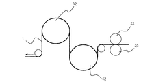
図2は、装置100に架設したワイヤ1の取付模式図である。
ワイヤ1は、図の右手に設置した図示しないワイヤドラムから装置100に供給される。
Embodiment 1 FIG.
Embodiment 1 of a tension applying device for a winding machine according to the present invention will be described below with reference to the drawings.
FIG. 1 is a perspective view of a tension applying device 100 (hereinafter, referred to as a device 100) of a winding machine.
FIG. 2 is a schematic diagram of attachment of the wire 1 installed on the
The wire 1 is supplied to the
図3は、装置100の押圧搬送機構20の斜視図である。
図4は、押圧搬送機構20の正面図である。
図5は、押圧搬送機構20の側面図である。
押圧搬送機構20は、電磁ブレーキ21の回転軸に接続されたテンションローラ22と、押圧ローラ23等で構成されている。
ワイヤ1はテンションローラ22と押圧ローラ23の間に挟み込まれてこれらの間を通過する。この時、テンションローラ22と押圧ローラ23は互いに逆方向に、それぞれの外周面が同じスピードで回転する。
押圧ローラ23は、回転自在のローラであり、リニアガイド24を介して、上下に動作するシリンダ25に接続されている。
このシリンダ25を上下に動作させることによって、押圧ローラ23のテンションローラ22に対する押圧力を調整できる。
そして、押圧ローラ23の押圧力と、回転抵抗付与機構としての電磁ブレーキ21の制動力によってワイヤ1にテンションを付与し、ワイヤ1が滑らないように制御する。
また、テンションローラ22の外周面はゴム又はシリコン加工を施してワイヤの滑りを防止する。
FIG. 3 is a perspective view of the
FIG. 4 is a front view of the
FIG. 5 is a side view of the
The pressing and
The wire 1 is sandwiched between the
The
By operating the
Then, tension is applied to the wire 1 by the pressing force of the
Further, the outer peripheral surface of the
図6(a)は、巻付テンション機構30の斜視図である。
図6(b)は、巻付テンション機構30の正面図である。
図6(c)は、巻付テンション機構30の側面図である。
巻付テンション機構30は、電磁ブレーキ31と、電磁ブレーキ31の回転軸に接続された巻付テンションローラ32で構成されている。
先に説明したテンションローラ22と、これから説明する巻付テンションローラ32は、いずれもワイヤ1に対してテンションを付与する点で機能は共通する。
しかし、巻付テンションローラ32は、ワイヤ1を巻き付けて、ローラ面とワイヤ1との摩擦力と電磁ブレーキ31の制動力によってテンションを付与する点が先のテンションローラ22と異なる。
FIG. 6A is a perspective view of the winding
FIG. 6B is a front view of the winding
FIG. 6C is a side view of the winding
The winding
Both the
However, the winding
押圧搬送機構20を通過したワイヤ1は、押圧搬送機構20の押圧ローラ23の上端部と、巻付テンション機構30の巻付テンションローラ32の下端部とを結ぶ直線上であって、巻付テンションローラ32の直近に設けたガイド7の横穴に導かれる。
そして、ワイヤ1は、巻付テンションローラ32に、下側から時計回りに概略3/4周分の角度に渡って巻き付けられる。
巻付テンションローラ32の外周は溝になっているのでワイヤ1が外れることはない。
また、巻付テンションローラ32の外周の溝面はゴム又はシリコン加工を施してワイヤの滑りを防止する。
The wire 1 that has passed through the pressing and conveying
Then, the wire 1 is wound around the winding
Since the outer periphery of the winding
Further, the outer peripheral groove surface of the winding
図7(a)は、巻付テンション機構40の斜視図である。
図7(b)は、巻付テンション機構40の正面図である。
図7(c)は、巻付テンション機構40の側面図である。
巻付テンション機構40は、回転抵抗付与機構としてのサーボモータ41と、サーボモータ41の回転軸に接続された巻付テンションローラ42で構成されている。
ワイヤ1は、先述のガイド7の縦穴を通って、巻付テンションローラ32の右端部と巻付テンションローラ42の左端部とを結ぶ直線上であって、巻付テンションローラ42の直近に設けたガイド10の縦穴に導かれる。
FIG. 7A is a perspective view of the winding
FIG. 7B is a front view of the winding
FIG. 7C is a side view of the winding
The winding
The wire 1 is provided on the straight line connecting the right end portion of the winding
そして、ワイヤ1は、巻付テンションローラ42に、向かって左端から反時計回りに概略3/4周分の角度に渡って巻き付けられる。
その後、ワイヤ1は、先のガイド10の横穴を通って、図示しないノズルを介して被巻線体に供給される。
Then, the wire 1 is wound around the winding
Thereafter, the wire 1 is supplied to the wound body through a nozzle (not shown) through the horizontal hole of the
次に、ワイヤ1に付与されるテンションについて、図2を用いて説明する。
押圧搬送機構20のテンションローラ22によってワイヤ1に発生するテンションF1は、
電磁ブレーキ21による摩擦トルクをτ1とし、テンションローラ22の半径をr1とするとき、次式で表される。
F1=τ1/r1
Next, tension applied to the wire 1 will be described with reference to FIG.
The tension F1 generated in the wire 1 by the
When the friction torque by the
F1 = τ1 / r1
次に、巻付テンション機構30の巻付テンションローラ32によって発生するテンションF2は、電磁ブレーキ31による摩擦トルクをτ2、巻付テンションローラ32の半径をr2とするとき、次式で表される。
F2=τ2/r2
Next, the tension F2 generated by the winding
F2 = τ2 / r2
このとき、巻付テンションローラ32の巻き付け角θ2及び、巻付テンションローラ32とワイヤ1の摩擦係数μ2を用いて、オイラーのベルト理論により次式の条件を設定する。
F2≦F1・exp(μ2・θ2)
F2の値がこの条件を満たすようにτ2の値を制御することによって、巻付テンションローラ32とワイヤ1の間での滑りの発生を防止できる。
At this time, using the winding angle θ 2 of the winding
F2 ≦ F1 · exp (μ2 · θ2)
By controlling the value of τ2 so that the value of F2 satisfies this condition, the occurrence of slippage between the winding
同様に、巻付テンション機構40の巻付テンションローラ42によって発生するテンションF3は、サーボモータ41による摩擦トルクをτ3、巻付テンションローラ42の半径をr3とするとき、次式で表される。
F3=τ3/r3
Similarly, the tension F3 generated by the winding
F3 = τ3 / r3
このとき、巻付テンションローラ42の巻き付け角θ3及び、巻付テンションローラ42とワイヤ1の摩擦係数μ3を用いて、オイラーのベルト理論により次式の条件が設定する。
F3≦(F1+F2)・exp(μ3・θ3)
F3の値がこの条件を満たすようにτ3の値を制御することによって、巻付テンションローラ42とワイヤ1の間での滑りの発生を防止できる。
At this time, using the winding angle θ3 of the winding
F3 ≦ (F1 + F2) · exp (μ3 · θ3)
By controlling the value of τ3 so that the value of F3 satisfies this condition, the occurrence of slippage between the winding
以上の結果、被巻線体にかかるテンションは、F1、F2及びF3の総和となる。
また、各条件設定を満たす限り、ワイヤ1と各テンションローラは、転がりによる相対運動をし、滑り運動は発生しない。
As a result, the tension applied to the wound body is the sum of F1, F2, and F3.
In addition, as long as each condition setting is satisfied, the wire 1 and each tension roller perform relative motion due to rolling, and no sliding motion occurs.
本実施の形態では、巻付テンション機構30には電磁ブレーキ31を使用し、巻付テンション機構40にはサーボモータ41を使用して、ワイヤ1に付与するテンションを調整した。
この理由は、サーボモータ41による調整は、電磁ブレーキ31による調整に比べて微妙な制御が可能だからである。
しかしながら、ワイヤの太さや種類によって電磁ブレーキだけで構成しても良いし、サーボモータだけで構成しても良い。
In this embodiment, the tension applied to the wire 1 is adjusted by using the
This is because the adjustment by the
However, depending on the wire thickness and type, the electromagnetic brake may be used alone, or the servo motor may be used alone.
シリンダ25の押圧力、電磁ブレーキ31とサーボモータ41の回転抵抗の付与は、以下のように行う。
(1)まず、テンションローラ22と押圧ローラ23の間にワイヤ1を挟んだ状態で、シリンダ25に適当な押圧指令を仮出力する。
(2)次に、電磁ブレーキ21に対して適当な制動指令値を出力する。
(3)手作業でワイヤ1を引き出し、この時にワイヤ1に付与されているテンションを測定する。
(4)測定したテンションを元に、先の各指令値を増減させて所望のテンションを得る。
(5)次に、巻付テンション機構30にワイヤ1を巻き付ける。
(6)巻付テンション機構30に回転抵抗を付与する適度な指令を与える。
(7)手作業でワイヤ1を引き出し、ワイヤ1に付与されたテンションを測定する。
(8)測定したテンションを元に、巻付テンション機構30に与えた指令値を増減させて所望のテンションを得る。
(9)次に、巻付テンション機構40にもワイヤ1を巻き付けてサーボモータ41に与える指令値の設定を同様におこなう。
The pressing force of the
(1) First, an appropriate pressing command is temporarily output to the
(2) Next, an appropriate braking command value is output to the
(3) The wire 1 is pulled out manually, and the tension applied to the wire 1 at this time is measured.
(4) Based on the measured tension, the desired values are obtained by increasing or decreasing the previous command values.
(5) Next, the wire 1 is wound around the winding
(6) An appropriate command for giving rotational resistance to the winding
(7) The wire 1 is pulled out manually and the tension applied to the wire 1 is measured.
(8) Based on the measured tension, the command value applied to the winding
(9) Next, the wire 1 is wound around the winding
図8は、巻付テンションローラの他の配置例を示す図である。
巻付テンションローラの配置は先に説明した配置に限られるものではなく例えば図8のような配置であっても良い。また、巻付テンションローラは2個に限られるものでもなく3個以上でも良い。
FIG. 8 is a view showing another arrangement example of the winding tension roller.
The arrangement of the winding tension roller is not limited to the arrangement described above, and may be an arrangement as shown in FIG. Further, the winding tension roller is not limited to two, and may be three or more.
なお、同じ装置100の設置スペース内で、巻付テンションローラ32、42に対するワイヤ1の巻き付け角度を大きく取るためには、巻付テンションローラ32と巻付テンションローラ42へのワイヤ1の巻き付けは、8の字を描くようにする方が有利である。
In order to increase the winding angle of the wire 1 around the winding
本発明の実施の形態1に係る巻線機のテンション付与装置100によれば、テンションローラ22と押圧ローラ23によって十分なテンションをワイヤ1に付与することができる。
また、ワイヤ1と、巻付テンションローラ32及び巻付テンションローラ42との間でも滑りが発生せず、ワイヤ1に付与する最大テンションを大きくすることができる。
また、ワイヤ1が各部品との間で摺動摩擦しないので、ワイヤ1の絶縁被覆へのダメージを与えずに十分に高いテンションをワイヤ1に付与できる。
According to the
Further, no slip occurs between the wire 1 and the winding
Moreover, since the wire 1 does not slide and friction with each component, a sufficiently high tension can be applied to the wire 1 without damaging the insulating coating of the wire 1.
実施の形態2.
以下、本発明に係る巻線機のテンション付与装置の実施の形態2を、図を用いて実施の形態1と異なる部分を中心に説明する。
図9(a)は、巻線機のテンション付与装置に架設したワイヤ1の取付模式図である。
図9(a)に示すワイヤ1の取り回し順は、実施の形態1とまったく同じである。
本実施の形態では、巻付テンションローラ232と巻付テンションローラ242との間に、中間ローラ50を設けている。
この中間ローラ50を使用すると、例えば図9(a)のように2個の巻付テンションローラを使用したり、図9(b)のように中間ローラ50からワイヤ1を直接ノズルに導いて巻付テンションローラ242を使用しない運用をしたりできる。
Embodiment 2. FIG.
Hereinafter, a second embodiment of a tension applying device for a winding machine according to the present invention will be described with reference to the drawings, focusing on portions different from the first embodiment.
FIG. 9A is a schematic view of the attachment of the wire 1 installed on the tension applying device of the winding machine.
The order of handling the wires 1 shown in FIG. 9A is exactly the same as in the first embodiment.
In the present embodiment, an
When this
同じ巻線機を使用して様々なコイルを巻線する場合、コイルの大きさや、ワイヤの太さ、線材によって付与するテンションは様々である。
実施の形態1では押圧ローラ、電磁ブレーキ、サーボモータを使用してテンションを調整したが、付与するテンションを大きく変更するには、使用する巻付テンションローラの数を調整することが効果的である。
When various coils are wound by using the same winding machine, the size of the coil, the thickness of the wire, and the tension applied depending on the wire material are various.
In the first embodiment, the tension is adjusted using a pressing roller, an electromagnetic brake, and a servo motor. However, in order to greatly change the tension to be applied, it is effective to adjust the number of winding tension rollers to be used. .
本実施の形態の巻線機のテンション付与装置によれば、巻付テンションローラ間に中間ローラ50を設けるだけで容易にテンションを大きく変更して様々な線材に対応することができる。
According to the tension applying device for a winding machine according to the present embodiment, it is possible to easily change the tension greatly only by providing the
実施の形態3.
以下、本発明に係る巻線機のテンション付与装置の実施の形態3を、図を用いて実施の形態1と異なる部分を中心に説明する。
図10(a)は、巻線機のテンション付与装置に架設したワイヤ1の取り付け模式図である。
本実施の形態では、各巻付テンションローラに巻き付けるワイヤ1の巻き付け角度を調整できるように移動ローラ350、351を備えている。
図10(b)に示すように、移動ローラ350、351を左右に移動することによって容易に各巻付テンションローラに対するワイヤ1の巻き付け角度を調整できる。
ワイヤ1の巻き付け角度を大きくすることによって、ワイヤ1に付与できるテンションを大幅に増加できる。
Embodiment 3 FIG.
Hereinafter, a third embodiment of a tension applying device for a winding machine according to the present invention will be described with reference to the drawings, focusing on the differences from the first embodiment.
Fig.10 (a) is a schematic diagram of attachment of the wire 1 installed in the tension applying device of the winding machine.
In this embodiment, moving
As shown in FIG. 10B, the winding angle of the wire 1 with respect to each winding tension roller can be easily adjusted by moving the moving
By increasing the winding angle of the wire 1, the tension that can be applied to the wire 1 can be significantly increased.
実施の形態4.
以下、本発明に係る巻線機のテンション付与装置の実施の形態4を、図を用いて実施の形態1と異なる部分を中心に説明する。
図11は、機械式ブレーキ60の断面模式図である。
本実施の形態では電磁ブレーキや、サーボモータの代わりに、機械式ブレーキ60を使用してワイヤ1にテンションを付与する。
巻付テンションローラの軸63は、粘性流体64を充填したハウジング61に回転可能に軸支持されている。
ハウジング61の中の軸63には、はねが取り付けられており、回転時に粘性流体64を受けて回転抵抗が生じる。
Embodiment 4 FIG.
Hereinafter, a tension applying device for a winding machine according to a fourth embodiment of the present invention will be described with reference to the drawings, focusing on the differences from the first embodiment.
FIG. 11 is a schematic sectional view of the
In this embodiment, a tension is applied to the wire 1 using a
The winding
Splashes are attached to the
本発明の実施の形態4に係る機械式ブレーキ60によれば、簡便な構造で一定の制動力を確保できる。
これにより、低コストな巻線機のテンション付与装置を提供できる。
According to the
Thereby, a low-cost winding machine tensioning device can be provided.
r1,r2,r3 半径、F1,F2,F3 テンション、20 押圧搬送機構、
21,31 電磁ブレーキ、22 テンションローラ、23 押圧ローラ、
24 リニアガイド、25 シリンダ、30,40 巻付テンション機構、
32,42,232,242 巻付テンションローラ、41 サーボモータ、
7,10 ガイド、50 中間ローラ、350,351 移動ローラ、
60 機械式ブレーキ。
r1, r2, r3 radius, F1, F2, F3 tension, 20 pressure transport mechanism,
21, 31 Electromagnetic brake, 22 tension roller, 23 pressure roller,
24 linear guide, 25 cylinder, 30, 40 winding tension mechanism,
32, 42, 232, 242 Winding tension roller, 41 Servo motor,
7,10 guide, 50 intermediate roller, 350,351 moving roller,
60 Mechanical brake.
Claims (10)
前記回転抵抗付与機構を備えた回転自在のテンションローラと、前記テンションローラの外周面に前記ワイヤを挟んで押圧しながら、前記外周面の回転スピードに合わせて前記テンションローラと反対方向に回転して前記ワイヤを前記巻付テンションローラに送出する押圧ローラとを有する押圧搬送機構を備え、
前記巻付テンションローラに巻き付けられる前の前記ワイヤを通す第一穴と前記巻付テンションローラに巻き付けられた後の前記ワイヤを通す第二穴とを有するガイドを備えた巻線機のテンション付与装置。 In a tension applying device of a winding machine provided with a winding tension mechanism that winds a wire around a winding tension roller provided with a rotation resistance applying mechanism, and applies tension to the wire by rotation resistance of the winding tension roller.
A rotatable tension roller provided with the rotational resistance applying mechanism, and rotating in the opposite direction to the tension roller according to the rotation speed of the outer peripheral surface while pressing the outer peripheral surface of the tension roller with the wire interposed therebetween. A pressure conveying mechanism having a pressure roller for feeding the wire to the winding tension roller;
A tension applying device for a winding machine comprising a guide having a first hole through which the wire is wound before being wound around the winding tension roller and a second hole through which the wire is wound after being wound around the winding tension roller. .
Priority Applications (1)
| Application Number | Priority Date | Filing Date | Title |
|---|---|---|---|
| JP2011153394A JP5744651B2 (en) | 2011-07-12 | 2011-07-12 | Winding machine tensioning device |
Applications Claiming Priority (1)
| Application Number | Priority Date | Filing Date | Title |
|---|---|---|---|
| JP2011153394A JP5744651B2 (en) | 2011-07-12 | 2011-07-12 | Winding machine tensioning device |
Publications (3)
| Publication Number | Publication Date |
|---|---|
| JP2013021137A JP2013021137A (en) | 2013-01-31 |
| JP2013021137A5 JP2013021137A5 (en) | 2013-11-28 |
| JP5744651B2 true JP5744651B2 (en) | 2015-07-08 |
Family
ID=47692286
Family Applications (1)
| Application Number | Title | Priority Date | Filing Date |
|---|---|---|---|
| JP2011153394A Active JP5744651B2 (en) | 2011-07-12 | 2011-07-12 | Winding machine tensioning device |
Country Status (1)
| Country | Link |
|---|---|
| JP (1) | JP5744651B2 (en) |
Families Citing this family (3)
| Publication number | Priority date | Publication date | Assignee | Title |
|---|---|---|---|---|
| CN106683875B (en) * | 2017-01-19 | 2019-03-08 | 厦门大一互科技有限公司 | A kind of mutual inductor primary line copper strips fastener |
| CN111971244B (en) * | 2018-04-26 | 2022-04-05 | 三菱电机株式会社 | Tension adjusting device, winding device, and method for manufacturing rotating electric machine |
| CN112770993B (en) * | 2018-08-17 | 2023-11-28 | 施洛伊尼格股份公司 | Conductor braking device and method |
Family Cites Families (8)
| Publication number | Priority date | Publication date | Assignee | Title |
|---|---|---|---|---|
| JPS518996Y2 (en) * | 1972-07-17 | 1976-03-10 | ||
| JPS6117970Y2 (en) * | 1980-10-31 | 1986-05-31 | ||
| JPH0790975B2 (en) * | 1987-04-15 | 1995-10-04 | 株式会社日立製作所 | Inertia peak tension compensation winding device |
| JPH05304039A (en) * | 1992-04-27 | 1993-11-16 | Matsushita Electric Ind Co Ltd | Winding device |
| JP3035094B2 (en) * | 1992-09-17 | 2000-04-17 | ティーディーケイ株式会社 | Tension generator |
| JPH09194136A (en) * | 1996-01-16 | 1997-07-29 | Sony Corp | Winding tension controller |
| JP4422826B2 (en) * | 1999-08-24 | 2010-02-24 | 田中精機株式会社 | Tension device |
| JP4581188B2 (en) * | 2000-06-13 | 2010-11-17 | 日産自動車株式会社 | Flat wire structure and flat wire winding method |
-
2011
- 2011-07-12 JP JP2011153394A patent/JP5744651B2/en active Active
Also Published As
| Publication number | Publication date |
|---|---|
| JP2013021137A (en) | 2013-01-31 |
Similar Documents
| Publication | Publication Date | Title |
|---|---|---|
| EP2617670B1 (en) | Tension device | |
| US20160354820A1 (en) | Wire straightening device | |
| JP5744651B2 (en) | Winding machine tensioning device | |
| RU2665668C2 (en) | Method and device for aligning metal strips by stretch bending | |
| WO2014192409A1 (en) | Binding device for rod-shaped body, bound body of rod-shaped body, and binding method for rod-shaped body | |
| JP2012505084A (en) | Tensile and / or straightening units for long metal products such as bars, rounds or metal wires | |
| CN103754692A (en) | Double sides setting wire-feed rack | |
| JP5623794B2 (en) | Back tension applying device for winding wire and method for applying back tension | |
| JP6448670B2 (en) | Tension roller, tension adjusting device, and electric motor manufacturing method | |
| EP3255002B1 (en) | Tensioning device | |
| TWI731160B (en) | Belt-type false-twisting device | |
| JP6087417B1 (en) | Feeding device | |
| JP2013021137A5 (en) | ||
| TW201521329A (en) | Active tension control device for a winding machine | |
| JP5846519B1 (en) | An endless winch and a rope moving method using the endless winch. | |
| EP2866236B1 (en) | Device for automatic wire tension adjustments during the various steps of winding in machines for winding electric coils | |
| US11167493B2 (en) | Device for controlling supply of a filament | |
| WO2016128309A1 (en) | Tension buffer system for multi-wire pay-off system | |
| KR100571605B1 (en) | Longitudinal taping apparatus for cable | |
| EP1977839A1 (en) | Dual pivot ironing roll | |
| JP2012228708A (en) | Sheet metal feeding device and press working line in which the sheet metal feeding device is arranged | |
| JP2012066295A (en) | Metal strip winding apparatus with double belt type belt wrapper, and method for metal strip winding by the same | |
| JP6838944B2 (en) | Winding equipment and winding method | |
| JP5915586B2 (en) | Steel strip meander control device and meander control method | |
| KR20130022915A (en) | Fly apparatus for windng machine |
Legal Events
| Date | Code | Title | Description |
|---|---|---|---|
| A521 | Request for written amendment filed |
Free format text: JAPANESE INTERMEDIATE CODE: A523 Effective date: 20131009 |
|
| A621 | Written request for application examination |
Free format text: JAPANESE INTERMEDIATE CODE: A621 Effective date: 20131009 |
|
| A977 | Report on retrieval |
Free format text: JAPANESE INTERMEDIATE CODE: A971007 Effective date: 20140714 |
|
| A131 | Notification of reasons for refusal |
Free format text: JAPANESE INTERMEDIATE CODE: A131 Effective date: 20140729 |
|
| A521 | Request for written amendment filed |
Free format text: JAPANESE INTERMEDIATE CODE: A523 Effective date: 20140926 |
|
| TRDD | Decision of grant or rejection written | ||
| A01 | Written decision to grant a patent or to grant a registration (utility model) |
Free format text: JAPANESE INTERMEDIATE CODE: A01 Effective date: 20150407 |
|
| A61 | First payment of annual fees (during grant procedure) |
Free format text: JAPANESE INTERMEDIATE CODE: A61 Effective date: 20150430 |
|
| R150 | Certificate of patent or registration of utility model |
Ref document number: 5744651 Country of ref document: JP Free format text: JAPANESE INTERMEDIATE CODE: R150 |
|
| R250 | Receipt of annual fees |
Free format text: JAPANESE INTERMEDIATE CODE: R250 |
|
| R250 | Receipt of annual fees |
Free format text: JAPANESE INTERMEDIATE CODE: R250 |
|
| R250 | Receipt of annual fees |
Free format text: JAPANESE INTERMEDIATE CODE: R250 |
|
| R250 | Receipt of annual fees |
Free format text: JAPANESE INTERMEDIATE CODE: R250 |
|
| R250 | Receipt of annual fees |
Free format text: JAPANESE INTERMEDIATE CODE: R250 |
|
| R250 | Receipt of annual fees |
Free format text: JAPANESE INTERMEDIATE CODE: R250 |