JP5740397B2 - Electromechanical motor - Google Patents
Electromechanical motor Download PDFInfo
- Publication number
- JP5740397B2 JP5740397B2 JP2012515363A JP2012515363A JP5740397B2 JP 5740397 B2 JP5740397 B2 JP 5740397B2 JP 2012515363 A JP2012515363 A JP 2012515363A JP 2012515363 A JP2012515363 A JP 2012515363A JP 5740397 B2 JP5740397 B2 JP 5740397B2
- Authority
- JP
- Japan
- Prior art keywords
- actuator
- interaction
- electromechanical
- electrical signal
- interaction part
- Prior art date
- Legal status (The legal status is an assumption and is not a legal conclusion. Google has not performed a legal analysis and makes no representation as to the accuracy of the status listed.)
- Expired - Fee Related
Links
- 230000003993 interaction Effects 0.000 claims description 78
- 239000000463 material Substances 0.000 claims description 28
- 230000008859 change Effects 0.000 claims description 14
- 238000000034 method Methods 0.000 claims description 10
- 230000004044 response Effects 0.000 claims description 9
- 238000006073 displacement reaction Methods 0.000 claims description 2
- 230000008021 deposition Effects 0.000 claims 1
- 230000008901 benefit Effects 0.000 description 9
- 210000004081 cilia Anatomy 0.000 description 9
- 230000001886 ciliary effect Effects 0.000 description 8
- 230000007246 mechanism Effects 0.000 description 8
- 238000005452 bending Methods 0.000 description 5
- 230000008602 contraction Effects 0.000 description 5
- 230000009471 action Effects 0.000 description 4
- 238000010586 diagram Methods 0.000 description 3
- 238000005336 cracking Methods 0.000 description 2
- 230000001419 dependent effect Effects 0.000 description 2
- 238000004519 manufacturing process Methods 0.000 description 2
- 230000010363 phase shift Effects 0.000 description 2
- 229920000642 polymer Polymers 0.000 description 2
- 239000007787 solid Substances 0.000 description 2
- 230000003068 static effect Effects 0.000 description 2
- 230000001429 stepping effect Effects 0.000 description 2
- 239000004642 Polyimide Substances 0.000 description 1
- 239000000919 ceramic Substances 0.000 description 1
- 239000002131 composite material Substances 0.000 description 1
- 239000013078 crystal Substances 0.000 description 1
- 230000002950 deficient Effects 0.000 description 1
- 230000009977 dual effect Effects 0.000 description 1
- 230000005611 electricity Effects 0.000 description 1
- 238000005516 engineering process Methods 0.000 description 1
- 230000005284 excitation Effects 0.000 description 1
- 229910002112 ferroelectric ceramic material Inorganic materials 0.000 description 1
- 239000000835 fiber Substances 0.000 description 1
- 230000006872 improvement Effects 0.000 description 1
- 230000004048 modification Effects 0.000 description 1
- 238000012986 modification Methods 0.000 description 1
- 238000013021 overheating Methods 0.000 description 1
- 229920001721 polyimide Polymers 0.000 description 1
- 238000003825 pressing Methods 0.000 description 1
- 230000008569 process Effects 0.000 description 1
- 230000009467 reduction Effects 0.000 description 1
Images


Classifications
-
- H—ELECTRICITY
- H02—GENERATION; CONVERSION OR DISTRIBUTION OF ELECTRIC POWER
- H02N—ELECTRIC MACHINES NOT OTHERWISE PROVIDED FOR
- H02N2/00—Electric machines in general using piezoelectric effect, electrostriction or magnetostriction
- H02N2/02—Electric machines in general using piezoelectric effect, electrostriction or magnetostriction producing linear motion, e.g. actuators; Linear positioners ; Linear motors
- H02N2/04—Constructional details
- H02N2/043—Mechanical transmission means, e.g. for stroke amplification
-
- H—ELECTRICITY
- H02—GENERATION; CONVERSION OR DISTRIBUTION OF ELECTRIC POWER
- H02N—ELECTRIC MACHINES NOT OTHERWISE PROVIDED FOR
- H02N2/00—Electric machines in general using piezoelectric effect, electrostriction or magnetostriction
-
- H—ELECTRICITY
- H02—GENERATION; CONVERSION OR DISTRIBUTION OF ELECTRIC POWER
- H02N—ELECTRIC MACHINES NOT OTHERWISE PROVIDED FOR
- H02N2/00—Electric machines in general using piezoelectric effect, electrostriction or magnetostriction
- H02N2/02—Electric machines in general using piezoelectric effect, electrostriction or magnetostriction producing linear motion, e.g. actuators; Linear positioners ; Linear motors
- H02N2/021—Electric machines in general using piezoelectric effect, electrostriction or magnetostriction producing linear motion, e.g. actuators; Linear positioners ; Linear motors using intermittent driving, e.g. step motors, piezoleg motors
-
- H—ELECTRICITY
- H02—GENERATION; CONVERSION OR DISTRIBUTION OF ELECTRIC POWER
- H02N—ELECTRIC MACHINES NOT OTHERWISE PROVIDED FOR
- H02N2/00—Electric machines in general using piezoelectric effect, electrostriction or magnetostriction
- H02N2/02—Electric machines in general using piezoelectric effect, electrostriction or magnetostriction producing linear motion, e.g. actuators; Linear positioners ; Linear motors
- H02N2/04—Constructional details
-
- H—ELECTRICITY
- H02—GENERATION; CONVERSION OR DISTRIBUTION OF ELECTRIC POWER
- H02N—ELECTRIC MACHINES NOT OTHERWISE PROVIDED FOR
- H02N2/00—Electric machines in general using piezoelectric effect, electrostriction or magnetostriction
- H02N2/02—Electric machines in general using piezoelectric effect, electrostriction or magnetostriction producing linear motion, e.g. actuators; Linear positioners ; Linear motors
- H02N2/06—Drive circuits; Control arrangements or methods
- H02N2/062—Small signal circuits; Means for controlling position or derived quantities, e.g. for removing hysteresis
-
- H—ELECTRICITY
- H10—SEMICONDUCTOR DEVICES; ELECTRIC SOLID-STATE DEVICES NOT OTHERWISE PROVIDED FOR
- H10N—ELECTRIC SOLID-STATE DEVICES NOT OTHERWISE PROVIDED FOR
- H10N30/00—Piezoelectric or electrostrictive devices
- H10N30/20—Piezoelectric or electrostrictive devices with electrical input and mechanical output, e.g. functioning as actuators or vibrators
- H10N30/202—Piezoelectric or electrostrictive devices with electrical input and mechanical output, e.g. functioning as actuators or vibrators using longitudinal or thickness displacement combined with bending, shear or torsion displacement
- H10N30/2023—Piezoelectric or electrostrictive devices with electrical input and mechanical output, e.g. functioning as actuators or vibrators using longitudinal or thickness displacement combined with bending, shear or torsion displacement having polygonal or rectangular shape
-
- H—ELECTRICITY
- H10—SEMICONDUCTOR DEVICES; ELECTRIC SOLID-STATE DEVICES NOT OTHERWISE PROVIDED FOR
- H10N—ELECTRIC SOLID-STATE DEVICES NOT OTHERWISE PROVIDED FOR
- H10N30/00—Piezoelectric or electrostrictive devices
- H10N30/20—Piezoelectric or electrostrictive devices with electrical input and mechanical output, e.g. functioning as actuators or vibrators
- H10N30/204—Piezoelectric or electrostrictive devices with electrical input and mechanical output, e.g. functioning as actuators or vibrators using bending displacement, e.g. unimorph, bimorph or multimorph cantilever or membrane benders
- H10N30/2041—Beam type
- H10N30/2042—Cantilevers, i.e. having one fixed end
Description
この発明は、電気機械式アクチュエーター装置とそのような装置を駆動する方法に関する。 The present invention relates to an electromechanical actuator device and a method for driving such a device.
極めて小さくされたモーターに対するニーズを伴う数々の応用例が存在している。例えば、消費財において、極めて小さくされ、軽量で、低電力消費で、しかも高価でないモーターが典型的には求められている。この運動のレンジは、しばしばミリメートルオーダーで要求精度はマイクロメーターである。数々の性能特性が求められ、たとえば高速度、運動静粛性、低電力消費、位置決め容易性、及び高い位置決め精度などで、これらは幾らか互いに矛盾するものである。 There are numerous applications with the need for extremely small motors. For example, consumer goods typically require motors that are extremely small, lightweight, low power consumption and inexpensive. The range of this movement is often in the order of millimeters and the required accuracy is micrometer. Numerous performance characteristics are required, such as high speed, quietness of movement, low power consumption, ease of positioning, and high positioning accuracy, which are somewhat inconsistent with each other.
高い位置決め精度と同時に比較的に制御の容易性を達成するために、ウォーキング機構、スティック−スリップ機構、「慣性」位置決め又はステップ機構など、異なる運動機構が選択される。このような原理で作動する大部分の装置に共通しているのは、アクチュエーターと被駆動の物体との高度の静的接触を伴うことである。位置決め精度は、この静的接触にかなり依存している。しかし、速度は、しばしば比較的遅く、装置はしばしば亜超音波周波数で動作し、騒音を出しパワー効率を低くする。このような典型例が、特許文献1である。 Different movement mechanisms are selected, such as walking mechanisms, stick-slip mechanisms, “inertial” positioning or step mechanisms, in order to achieve high positioning accuracy and relatively easy control. Common to most devices operating on this principle is the high degree of static contact between the actuator and the driven object. The positioning accuracy is highly dependent on this static contact. However, the speed is often relatively slow and the device often operates at sub-ultrasonic frequencies, making noise and reducing power efficiency. A typical example of this is Patent Document 1.
このような装置は、適切な駆動により、極めて滑らかで、それ故静粛運動を起こし、多くの高い性能要求の応用に向いている。この種の装置は、一般的に使用されるアクチュエーターの比較的に複雑な運動パターンに基づいている。これは、幾つかの異なる電圧信号が、良く制御された位相シフト及び/又は電圧カーブの形を伴うことを要求する。さらに、複雑な駆動パターンは、電気機械的に駆動しうる大きな体積を要求し、稼動中に熱を発生する。稼動中のアクチュエーターの変形は、異なる種類の材料応力を起こし、これが電極、端末及び/又は電気機械的に作用する材料自体のクラックを来たらせることもある。 Such a device, with proper drive, is very smooth and therefore quietly moving, making it suitable for many high performance demand applications. This type of device is based on a relatively complex movement pattern of commonly used actuators. This requires that several different voltage signals are accompanied by well-controlled phase shifts and / or voltage curve shapes. Furthermore, complex drive patterns require large volumes that can be driven electromechanically and generate heat during operation. Actuator deformation during operation can cause different types of material stresses, which can lead to cracking of the electrode, the terminal and / or the electromechanically acting material itself.
ある応用例では、滑らかな運動が同じほど重要でない。その代わり、速度の改善、耐用性および複雑さの解消が高い関心を引く。 In some applications, smooth motion is not as important. Instead, speed improvements, durability and complexity reduction are of great interest.
本発明の目的は、複雑でなく、妥当な速度と高耐用性でしかも高い位置決め精度を示すミニチュアモーターを提供することである。 It is an object of the present invention to provide a miniature motor that is not complex, has reasonable speed, high durability, and high positioning accuracy.
上の目的は、添付の独立クレームによる装置、システム及び方法により達成される。好ましい実施態様は、従属クレームにより定義されている。一般的に、第一の態様によれば、電気機械式モーターは、アクチュエーターアセンブリと物体とを有しており、この物体に対して、アクチュエーターアセンブリが作用して、この物体を駆動方向に偏位させる。アクチュエーターアセンブリは、アクチュエーター基台と、第一と第二のアクチュエーターとを有している。第一アクチュエーターは単一の取付部により機械的に取付けられる。第一アクチュエーターの単一取付部は、アクチュエーター基台への第一取付部である。第一取付部は、第一アクチュエーターの第一端に設けられている。第一アクチュエーターは、第一アクチュエーターの第二端を構成する第一相互作用部を有している。第一アクチュエーターの第二端は、アクチュエーター方向に見て第一アクチュエーターの第一端と反対にある。第二アクチュエーターは、第二取付部と第二相互作用部と共に同様に配置されている。アクチュエーター方向は、駆動方向と交差している。第一相互作用部と第二相互作用部は、それぞれの接触エリヤにおいて物体の相互作用面と相互作用をするように配置されている。第一アクチュエーターと第二アクチュエーターは、第一アクチュエーターと第二アクチュエーター夫々の第一端と第二端との間に配置された電気機械的材料を有するユニモルフ部材を有している。ユニモルフ部材の各々は、それぞれに掛けられる電気信号の応答として接触エリヤの運動を起こすように配置されている。各運度はアクチュエーター方向にも、駆動方向にもさらに互いにも交差している。 The above objective is accomplished by an apparatus, system and method according to the attached independent claims. Preferred embodiments are defined by the dependent claims. In general, according to a first aspect, an electromechanical motor has an actuator assembly and an object, against which the actuator assembly acts to displace the object in the driving direction. Let The actuator assembly has an actuator base and first and second actuators. The first actuator is mechanically attached by a single attachment. The single attachment portion of the first actuator is the first attachment portion to the actuator base. The first attachment portion is provided at the first end of the first actuator. The 1st actuator has the 1st interaction part which constitutes the 2nd end of the 1st actuator. The second end of the first actuator is opposite the first end of the first actuator when viewed in the direction of the actuator. The second actuator is similarly arranged with the second attachment portion and the second interaction portion. The actuator direction intersects the drive direction. The first interaction part and the second interaction part are arranged to interact with the interaction surface of the object in each contact area. The first actuator and the second actuator have a unimorph member having an electromechanical material disposed between a first end and a second end of each of the first actuator and the second actuator. Each of the unimorph members is arranged to cause movement of the contact area in response to an electrical signal applied thereto. Each run crosses both the actuator direction and the drive direction.
第二の態様によれば、電気機械式モーターシステムは、第一の態様に従う電気機械式モーターと、該電気機械式モーターに接続され、このユニモルフ部材の励起のために設けられた少なくとも二つの同じでない電気信号を与える電源とを有している。 According to a second aspect, an electromechanical motor system comprises an electromechanical motor according to the first aspect and at least two identical ones connected to the electromechanical motor and provided for excitation of the unimorph member. A power supply for providing a non-electrical signal.
第三の態様によれば、物体と相互作用するように配置された第一相互作用部と第二相互作用部とを有する電気機械式モーターを駆動する方法は、第一相互作用部に取付られた電気機械的材料を有するユニモルフ部材を励起するための第一の電気信号を与えるステップと、第二相互作用部に取付られた電気機械的材料を有するユニモルフ部材を励起するための第二の電気信号を与えるステップとを有している。第一の電気信号は第二の電気信号と異なっている。該第一の電気信号は、該第一相互作用部の該ユニモルフ部材が、該第一相互作用部の接触エリヤを、駆動方向と交差するが直交しない第一の運動方向に運動させる。該駆動方向は、該第一相互作用部と該第二相互作用部に対する物体の所期の前進移動方向である。該第二の電気信号は、該第二相互作用部の該ユニモルフ部材が、該第二相互作用部の接触エリヤを、駆動方向と交差する第二の運動方向に運動させる。該第二の運動方向は、該第一の運動方向と交差している。第一の電気信号と第二の電気信号は、駆動の間、該第一相互作用部と該第二相互作用部の少なくとも一つが該物体と接触せしめるようにされている。 According to a third aspect, a method of driving an electromechanical motor having a first interaction portion and a second interaction portion arranged to interact with an object is attached to the first interaction portion. Providing a first electrical signal for exciting a unimorph member having an electromechanical material and a second electricity for exciting the unimorph member having an electromechanical material attached to the second interaction portion. Providing a signal. The first electrical signal is different from the second electrical signal. The first electrical signal causes the unimorph member of the first interaction portion to move the contact area of the first interaction portion in a first movement direction that intersects the drive direction but is not orthogonal. The driving direction is an intended forward movement direction of the object with respect to the first interaction portion and the second interaction portion. The second electrical signal causes the unimorph member of the second interaction portion to move the contact area of the second interaction portion in a second movement direction that intersects the drive direction. The second movement direction intersects with the first movement direction. The first electrical signal and the second electrical signal are adapted to cause at least one of the first interaction portion and the second interaction portion to contact the object during driving.
この発明の利点は、ステップ運動がかなり複雑さが軽減されたアクチュエーター構造により達成されることと同時に高速と高耐用性を与えることである。 An advantage of the present invention is that it provides high speed and high durability while stepping motion is achieved by an actuator structure with significantly reduced complexity.
この発明は、その目的と利点と共に、添付された図面と共に以下の説明を参照することにより最も良く理解であろう。図面において、
図面全体を通して、同じ参照符号は、類似の対応要素のために用いられている。 Throughout the drawings, the same reference numerals are used for similar corresponding elements.
用語「交差する」は、交差方向に横たわるという通常の広い意味で用いられ、つまり、他のものを横切るもので、必ずしも直交するものではない。多くの場合、この用語は「平行でない」と同じ意味であると取る事ができる。 The term “intersect” is used in the usual broad sense of lying in the direction of crossing, that is, across other things, not necessarily orthogonal. In many cases, the term can be taken to mean the same as “not parallel”.
一次元的に動くアクチュエーターのセットは、相対運動を起こすためにその自由端で、物体に作用できる。このタイプの駆動機構は、その性質が繊毛システムと類似している故にしばしば繊毛運動機構と呼ばれている。一次元運動は、典型的には、被駆動面に対して法線力を与えるために駆動方向に対して幾らか傾斜している。繊毛運動は、共鳴作用により又はステップ機構として用いられることもある。 A set of one-dimensionally moving actuators can act on an object at its free end to cause relative motion. This type of drive mechanism is often referred to as a cilia movement mechanism because of its similar nature to the cilia system. One-dimensional motion is typically somewhat tilted with respect to the driving direction to provide a normal force to the driven surface. Ciliary movement may be used by resonance or as a step mechanism.
繊毛運動を使用したミクロメカニカルシステムの多くの例が存在する。例えば、Journal of Microelectromechanical systems,vol. 2, No. 4 Dec 1993に掲載の M Atka外著、「Fabrication and Operation of Polyimide Bimorph Actuators for a Ciliary Motion System」の記事にバイモルフ熱アクチュエーターの繊毛運動に基づくミクロ運動システムが開示されている。また、T. Hatsuzawa 著のSensors and Actuators A 105(2003) pp. 183-189に掲載の「A linear actuator based on cilia vibration」という記事には、繊毛ファイバーが外部振動機により刺激されている。しかし、このようなシステムのほとんどは、位置決めの精度が限定される。 There are many examples of micromechanical systems that use ciliary movement. For example, in the article “Fabrication and Operation of Polyimide Bimorph Actuators for a Ciliary Motion System” published by Journal of Microelectromechanical systems, vol. 2, No. 4 Dec 1993, An exercise system is disclosed. In the article “A linear actuator based on cilia vibration” published in Sensors and Actuators A 105 (2003) pp. 183-189 by T. Hatsuzawa, cilia fibers are stimulated by an external vibrator. However, most such systems have limited positioning accuracy.
しかし、この発明によれば繊毛運動は、電気機械式のアクチュエーター、例ピエゾアクチュエーターにより実行されるのに適している。アクチュエーターを機構的に単一取り付け部材により支持部に取付けることで堅固なベースとする。アクチュエーターをこの単一取り付け部材を除いて自由に動けるようにすることと動かされる物体との相互作用により、求められる運動を起こすために、アクチュエーターの電気機械的に能動体積部の寸法変化を利用する可能性が生まれる。この寸法変化は本質的に直に作用し、反復されるので、非常に正確な運動パターンが得られる。 However, according to the invention, the cilia movement is suitable to be performed by an electromechanical actuator, for example a piezo actuator. The actuator is mechanically attached to the support portion by a single attachment member to provide a solid base. Utilizing the electromechanical active volume dimensional change of the actuator to cause the desired movement by allowing the actuator to move freely except for this single mounting member and the interaction with the moved object Potential is born. This dimensional change is essentially straightforward and repeats, resulting in a very accurate motion pattern.
ユニモルフ部分を有する電気機械式アクチュエーターを使用することで、数々の利点が得られる。ユニモルフアクチュエーターは唯一つの電圧信号を必要とするのみであり、このことが電子制御の複雑さが極めて低いことを意味している。このユニモルフの作用が、類似のバイモルフ又はマルチモルフ構造に比較して発熱が少ない。このことは、過熱のリスクが無く速度を増すことができることを意味する。ユニモルフは、この能動体積部の小さい寸法変化をユニモルフの端部の大きな変位に変換するのにも有効である。同時にユニモルフは、アクチュエーターに沿う大きな力にも耐えるので、大きな法線力を加えることを可能とする。 Using an electromechanical actuator with a unimorph portion provides a number of advantages. Unimorph actuators only require one voltage signal, which means that the complexity of electronic control is very low. This action of the unimorph generates less heat than a similar bimorph or multimorph structure. This means that the speed can be increased without the risk of overheating. Unimorphs are also effective in converting small dimensional changes in this active volume into large displacements at the end of the unimorph. At the same time, unimorph can withstand large forces along the actuator, thus allowing large normal forces to be applied.
繊毛運動に基づいたあるアクチュエーターシステムは、一方向にのみ運動を与えることが可能である。このことは典型的には、大部分の駆動システムは、駆動される物体に作用する押し付け又は圧縮力を利用しているという事実に起因する。他のタイプの力のための構造配置は、典型的には達成するのが複雑である。繊毛運動を用いて物体を前後の両方に動かす可能性を達成するためには、互いに交差することを狙った運動方向を有する少なくとも二つのアクチュエーターが求められる。 Some actuator systems based on ciliary movement can only give movement in one direction. This is typically due to the fact that most drive systems utilize a pressing or compressive force acting on the driven object. Structural arrangements for other types of forces are typically complex to achieve. In order to achieve the possibility of moving the object both forward and backward using ciliary movement, at least two actuators with movement directions aimed at crossing each other are required.
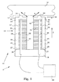
この発明による電気機械式モーター10の実施態様が図1に示めされている。電機機械式モーター10は、アクチュエーターアセンブリ12と物体14を有している。アクチュエーターアセンブリ12は、駆動方向4に物体14とアクチュエーターアセンブリ12との相対運動を起こさせるように物体14に作用するように配置されている。アクチュエーターアセンブリ12は、アクチュエーター基台16を有している。この実施例のアクチュエーターアセンブリ12は、第一アクチュエーター20と第二アクチュエーター22とを有している。アクチュエーター基台16は、この第一アクチュエーター20と第二アクチュエーター22の支持構造をなしている。
An embodiment of an
第一アクチュエーター20は、一つの取付部により機械的に取付られている。第一アクチュエーター20のこの取付部は基台16への第一取付部24である。換言すれば、第一アクチュエーター20は、アクチュエーターアセンブリの残りの部分に対して唯一の恒久的な機械的連結部である。この構成は、第一アクチュエーター20がこの第一取付部24を基準点として自由に動くのを許す。第一取付部24は第一アクチュエーター20の第一端25に設けられている。
The
第一アクチュエーター20は、アクチュエーター20の第二端31を構成する第一相互作用部30を有している。第一アクチュエーター20のこの第二端31は、アクチュエーターの方向5に見て、第一アクチュエーター20の第一端25と反対にある。第一相互作用部30は、接触エリヤ34において、物体34の作用面13と相互作用するように配置されている。このことは、アクチュエーター基台16への確実な連結部と物体14に対する接触エリヤ34が第一アクチュエーター20の互いに対抗する端に位置し、第一アクチュエーターがこれらの対抗端、即ち第一端25と第二端31の間において機械的接触がないよいうにする。アクチュエーター方向5は、駆動方向4に対して交差方向で、アクチュエーター方向5は好ましくは駆動方向4に対して直角又は実質的に直交している。
The
第一アクチュエーター20は、第一アクチュエーター20の第一端25と第二端31の間に、好ましくは第一端25と第二端31の距離全体又は実質的に全体に亘って配置された電気機械式材料ユニモルフ部材36を有している。この実施態様のユニモルフ部材36は、能動体積部40内に埋められた電極41に加えられる電気信号に応答して寸法変化を示す作動部分40を有している。この実施態様のユニモルフ部材36はさらに、アクチュエーター方向5に沿って能動体積部40に機械的に取付けられた受動体積部44を有している。能動体積部40と受動体積部44との接触面45がアクチュエーター方向5のユニモルフ部材36の全長に亘っても延びている。
The
能動体積部は、駆動電圧を低減するために、多層配置された電極とともに形成されている。標準的な配置は、図1に示されるように、電極にアクチュエーター方向5の表面を持たせることである。この配置は、大きなストロークを与える。これは、PZTのような圧電セラミックにおいては、圧電係数d33のこの方向の値が大きいからである。電極を他の方向、例えば、駆動方向4又は方向4および5と傾斜する方向に配置することも可能である。これらの場合には、係数d31はひずみを与え、この係数は係数d33より幾らか小さいが、壊れにくいとか製造が容易という利点がある。
The active volume is formed with electrodes arranged in multiple layers in order to reduce the drive voltage. A standard arrangement is to have the electrode have a surface in the
大部分のアクチュエーター材料は、電気機械的材料とされるが、この開示においては、電圧か電流が加えられたなら形状を変える材料を意図している。電気機械的材料の典型例は、圧電材料、電歪材料、反強誘電材料であり、これらの材料は単結晶及び多結晶または非結晶でありうる。今日最も興味が持たれている材料は、大きな電気機械的ひずみを有する多結晶多層強誘電セラミック材料であるが、比肩しえる特性を備える現在発展中のポリマー及びポリマー複合材もある。圧電材料と電歪材料が現在はベストであると考えられる。 Although most actuator materials are electromechanical materials, this disclosure contemplates materials that change shape when a voltage or current is applied. Typical examples of electromechanical materials are piezoelectric materials, electrostrictive materials, antiferroelectric materials, and these materials can be single crystal and polycrystalline or amorphous. The materials of most interest today are polycrystalline multilayer ferroelectric ceramic materials with large electromechanical strains, but there are also currently developing polymers and polymer composites with comparable properties. Piezoelectric and electrostrictive materials are currently considered the best.
ユニモルフ部材36は、電極41に加えられた電気信号の反応としての接触エリヤ34の運動を起こさせるように配置される。そのような電気信号が加えられると、能動体積部40は、典型的にはアクチュエーター方向に寸法が変化するが、能動体積部40は、ユニモルフ部材36の長さに沿って受動体積部44にしっかりと連結されているので、このような寸法変化は、ユニモルフ部材36の曲げを来たらせる。寸法変化が収縮の場合は、ユニモルフ部材36は、(図1において)左に曲がるが、寸法変化が膨張の場合には、ユニモルフ部材36は右に曲がる。接触エリヤ34は、これに伴い移動し、第一の運動方向6に沿う移動パスを与える。この第一運動方向6はアクチュエーター方向5とも駆動方向4とも交差している。この第一運動方向6は、駆動方向4に対しても直交せず、このことは接触エリヤ34の運動は駆動方向4の成分を持つことを意味する。
第二のアクチュエーター22は同様に配置されており、この実施態様では、第一アクチュエーター20と第二アクチュエーター22は互いに鏡対称的に配置されている。第二アクチュエーター22は、それ故に単一取付部により機械的に取付けられている。第二アクチュエーター20の単一取付部は、アクチュエーター基台16に対する第二取付部26である。第二取付部26は、第二アクチュエーター22の第一端27に設けられている。第二アクチュエーター22は、第二アクチュエーター22の第二端33を構成する第二相互作用部32を有している。第二アクチュエーター20のこの第二端33は、アクチュエーター方向5に見て、第二アクチュエーター22の第一端27と対向している。第二相互作用部32は、物体14の作用面13が接触エリヤ35により、相互作用するように配置されている。
The
第二アクチュエーター20は、第二アクチュエーター22の第一端27と第二端33との間に配置された電気機械的材料を有するユニモルフ部材38を有している。この実施態様のユニモルフ部材38は、能動体積部42に埋め込まれた電極43に加えられた電気信号におうじて寸法変化を示す能動体積部42を有する。この実施態様のユニモルフ部材38は、さらにアクチュエーター方向5に沿って能動体積部42に機械的に取付けられた受動体積部46を有する。能動体積部42と受動体積部46との接触面47がアクチュエーター方向5のユニモルフ部材38の全長に亘っても延びている。
The
ユニモルフ部材38は、電極43に加えられた電気信号の反応としての接触エリヤ35の運動を起こさせるように配置される。電極43に加えられた電気信号の反応として、能動体積部42の寸法変化が収縮の場合には、ユニモルフ部材38は(図1に示されるように)右に曲がり、寸法変化が膨張の場合には、ユニモルフ部材38は左に曲がる。接触エリヤはそれに応じて運動し、第二運動方向7に沿う移動パスを与える。第二運動方向7は、アクチュエーター方向5にも駆動方向4に対しても交差している。第二運動方向7は、さらに駆動方向4に対しても非直角であり、このことは接触エリヤ35の運動は駆動方向4の成分を有することを意味する。
The
この実施態様においては、第一アクチュエーター20の能動体積部40は、駆動方向4において受動体積部44の前に位置し、第二アクチュエーター22の能動体積部42は駆動方向4において受動体積部46の後に位置している。このようにして、第一運動方向6は第二運動方向7と異なっている。換言すれば、第一運動方向6と第二運動方向7は互いに交差している。この実施態様においては、鏡対称により第二運動方向7は、アクチュエーター方向5に平行な鏡面に関して第一運動方向6の鏡方向となる。換言すれば、能動および受動体積部の相対位置は下に説明するように反対にできる。
In this embodiment, the
上に述べたように、能動体積部40、42は電気信号を与えることにより作用させられる。この目的のために、電気機械式モーター10を有する電気機械式モーターシステム1は、電気機械式モーター10に連結され、ユニモルフ部材36、38を活性化するために少なくとも二つの同じでない電気信号を与えるようにされた給電装置99を有している。
As stated above, the
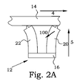
アクチュエーターの接触エリヤの一次元運動は、比較的簡単な電気信号により繊毛運動の原理、より厳密に言えば、二重繊毛運動原理で動作する配置へ結合することができる。図2A-Dは、このような駆動機構の実施態様を概観的に図示している。基本原理を明確に説明するために、図にはユニモルフの寸法変化が、それに伴い曲げストロークが極めて誇張されていることに注意されたい。実際は寸法変化と曲げストロークはアクチュエーターの全体の大きさに比べれば極めて小さい。 The one-dimensional motion of the actuator contact area can be coupled by a relatively simple electrical signal to an arrangement that operates on the principle of cilia movement, more precisely, on the principle of double cilia movement. Figures 2A-D schematically illustrate an embodiment of such a drive mechanism. To clearly explain the basic principle, it should be noted that the unimorph's dimensional change is accompanied by a very exaggerated bending stroke. Actually, the dimensional change and bending stroke are extremely small compared to the overall size of the actuator.
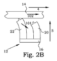
図2Aでは、両能動体積部がアクチュエーター方向に膨張させる電気信号が与えられている。これは、両アクチュエーター20,22を互いに外側に曲がらせる。物体14は、両アクチュエーター20、22と接触している。この位置から、第一アクチュエーター20は、後に曲げられる。第一アクチュエーター20の全長は小さくされ、即ち接触エリヤは矢印100で示される方向に移動する。これは第一アクチュエーター20の先端を物体14から開放するが、物体14は、第二アクチュエーター22に支持されているのでそれ自体は動かない。第一アクチュエーター20の能動体積部の収縮が終われば、第一アクチュエーターは図2Bに示されるように、左側により少ない長さだけ曲げられる。この状態から第二アクチュエーター22は曲げ返され、第二アクチュエーター22の接触エリヤは矢印101に沿って動く。物体14は第二アクチュエーター22のみに支持されているので、物体14は、その運動に従う。こうして矢印102に示される駆動方向の運動成分が与えられる。ここでは、物体14とアクチュエーターアセンブリ12を一緒にしておく法線方向の力の存在を前提としている。
In FIG. 2A, an electrical signal is provided that causes both active volumes to expand in the direction of the actuator. This causes both
第二アクチュエーター22の曲げ動作が終わると、図2Cに示された状況になる。物体14は再び両アクチュエーター20、22と接触する。第一アクチュエーター20に再び電気信号が与えられ、第一アクチュエーターのユニモルフがもう一度矢印103の方向に曲げられる。この運動は第二アクチュエーター22と物体14との接触を離す。物体はこれにより、第一アクチュエーター20の運動に追従し、駆動方向の運動成分が与えられる。ついで図2Dに示される状態に至る。ここで、第二アクチュエーター22は、運動105により、図2Aの元の位置を回復するために再び曲がる。図2Aに示される状態が再び得られるが、物体14は駆動方向にある距離移動している。
When the bending operation of the
このようにして駆動作用が達成される。電気信号を反対に与えることで、駆動作用も反対方向に与えることができる。 In this way, a driving action is achieved. By providing the electrical signal in the opposite direction, the driving action can be applied in the opposite direction.
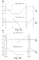
図3Aには、第一アクチュエーターと第二アクチュエーターの駆動電圧がどのようになるかの実施態様として二つの電圧カーブが示されている。上のカーブは図2A−Dの第一アクチュエーターに掛けられた電圧を示し、下のカーブは第二アクチュエーターに掛けられた電圧を示す。ここでは、正の電圧は能動体積部の膨張を起こし、負の電圧は能動体積部の収縮を起こすと仮定している。時間軸の下の文字は図2A−Dの異なる状態を示す。二つのアクチュエーターの間で90度位相シフトした単一の電圧カーブがステップ動作を起こすために使用することができる。この実施態様の小さな不利といえば、物体が周期の半分(BとDとの間)だけ積極的に駆動され残りの期間(AとB,およびDとAの間)は静止していることである。 FIG. 3A shows two voltage curves as an embodiment of how the driving voltages of the first actuator and the second actuator become. The upper curve shows the voltage applied to the first actuator of FIGS. 2A-D, and the lower curve shows the voltage applied to the second actuator. Here, it is assumed that a positive voltage causes expansion of the active volume and a negative voltage causes contraction of the active volume. The letters below the time axis indicate the different states in FIGS. 2A-D. A single voltage curve 90 degrees phase shifted between the two actuators can be used to cause the stepping action. The small disadvantage of this embodiment is that the object is actively driven by half the period (between B and D) and is stationary for the rest of the period (between A and B, and D and A). is there.
図3Bは、駆動電圧の他の実施態様を示す。ここでは物体が休止の時間が少なくなるように及び選択的に積極駆動の時間が増すようにA−Dの間の状態は変更されている。より早い又は少なくともより滑らかな物体の運動が達成できる。このようなケースでは、異なるアクチュエーターに同一波形の電圧を加えることはできない。このようなケースでは、異なる波形のカーブを与えなければならない。 FIG. 3B shows another embodiment of the drive voltage. Here, the state between A and D is changed so that the time for the object to pause is reduced and the time for active driving is selectively increased. Faster or at least smoother object motion can be achieved. In such a case, the same waveform voltage cannot be applied to different actuators. In such cases, different waveform curves must be provided.
図3Cは、駆動電圧のさらに別の実施態様を示す。これらの電圧は、上述のアクチュエーターを用いて二重繊毛運動を起こすが、図2A−Dに示されたのとは少し方法が異なる。図2Bと2Dに示された状態は実際には実現できない。この例では、第二アクチュエーターの収縮動作は第一アクチュエーターの収縮がスタートした後ほんの少し経った時間Eにスタートする。第一アクチュエーターが時間Fにおいて最も収縮した状態に至ると、第二アクチュエーターもほぼ完全に収縮する。図2Cに示される状態になるまで、物体はここでも第二アクチュエーターのみに接触している。第一アクチュエーターは膨張を開始し物体への接触を受け継ぐ。時間Gにおいて、第二アクチュエーターも膨張を開始し、時間Hにおいて、第一アクチュエーターが最も膨張した状態になると、第二アクチュエーターもほぼ完全に膨張する。物体が休止の時間は時間Hと次のサイクルの時間Eの間に限られる。 FIG. 3C shows yet another embodiment of the drive voltage. These voltages cause double ciliary movement using the actuators described above, but are slightly different from those shown in FIGS. 2A-D. The state shown in FIGS. 2B and 2D cannot be realized in practice. In this example, the contraction operation of the second actuator starts at time E, which is a little after the contraction of the first actuator has started. When the first actuator reaches its most contracted state at time F, the second actuator contracts almost completely. Again, the object is in contact only with the second actuator until the state shown in FIG. 2C is reached. The first actuator begins to expand and inherits contact with the object. At time G, the second actuator also begins to expand, and at time H, when the first actuator reaches its most expanded state, the second actuator also expands almost completely. The time for the object to rest is limited between time H and time E of the next cycle.
図3Dは、同じ課題の他の実施例を示す。ここでは、電圧は最小の休止時間となるように最適化されている。当業者なら、二重繊毛運動を得るためにどのように電圧を与えるかの数々の方法があることを悟る。位相シフトをした単純な波型、正弦波又は三角波の電圧カーブが使用できる。あるケースでは、物体の運動は、往復運動期間を持ち幾らか奇妙であるが、正味の予定方向運動を達成できる。 FIG. 3D shows another embodiment of the same problem. Here, the voltage is optimized to have a minimum downtime. Those skilled in the art realize that there are numerous ways of applying voltage to obtain a double cilia movement. A simple wave, sinusoidal or triangular voltage curve with phase shift can be used. In some cases, the motion of the object is somewhat strange with a reciprocating period, but can achieve a net planned direction of motion.
ここでは、上述の運動パターンがユニモルフを用いて、即ち、電気機械的に能動部分と同じように一体化された電気機械的に受動的な部材を用いて、達成できる。同じ種類の運動パターンが、機械的に連結された二つの能動部分をもつバイモルフのような、もっと精巧なアクチュエーターを用いて達成することも可能であろう。しかし、このような構成は駆動がより複雑でユニモルフが持つような安定性の利点は与えない。下の説明を参照。従って、ユニモルフは、現在好まれるこの発明の理念を完成する要素である。 Here, the above-mentioned movement pattern can be achieved with unimorph, ie with an electromechanically passive member integrated in the same way as the electromechanically active part. The same type of motion pattern could be achieved using a more sophisticated actuator, such as a bimorph with two mechanically connected active parts. However, such a configuration is more complex to drive and does not provide the stability advantage that unimorph has. See description below. Thus, unimorph is the element that completes the presently preferred idea of the invention.
アクチュエーター方向が、駆動方向と直交又は実質的に直交している場合には、ユニモルフの使用が利点を有している。アクチュエーターの受動部分が、アクチュエーターアセンブリと物体との間の比較的に高い法線力に対する堅固な支持部を与える。同時にこの同じ部材が、アクチュエーター方向とも駆動方向とも平行でない運動を起こす部材である。好ましいさらに別の実施態様のさらなる利点が以下に示される。 Use of a unimorph has advantages when the actuator direction is orthogonal or substantially orthogonal to the drive direction. The passive part of the actuator provides a solid support for the relatively high normal force between the actuator assembly and the object. At the same time, this same member is a member that causes a motion that is not parallel to the actuator direction or the drive direction. Further advantages of yet another preferred embodiment are shown below.
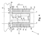
図1の実施態様においては、アクチュエーターの能動体積部は互いに向き合っており、このことは、能動体積部の膨張に伴う第一と第二の運動方向6、7は互いに離れるように向いていることを意味する。図4に示されるようにこの反対も勿論可能である。ここでは、アクチュエーター20、22の能動体積部40、42は互いから離れるように向いている。このことから、第一と第二の運動方向6、7は、図1に示された状態と比較して、鏡対称方向に向くことになる。
In the embodiment of FIG. 1, the active volume of the actuator faces each other, which means that the first and
図4において、相互作用部30、32の接触エリヤ34、35は夫々のアクチュエーター20、22の外端に近接して設けられている。換言すれば、接触エリヤは、夫々のアクチュエーター20、22の中央線3から駆動方向4の方向に偏位して位置している。この配置は、てこ作用が増大されるという利点を有する。接触エリヤが位置する位置は中央線3に位置する接触エリヤより大きなストロークを与える。このようにして、各サイクルのステップサイズを増すことができ、得られる最大スピードを増すことができる。
In FIG. 4, the
この特性は図5においてさらに発展しており、ここでは相互作用部30、32はアクチュエーター断面のメイン部から外に延ばされている。第一相互作用部30は、延出部37を有し、駆動方向4に沿う方向、ここでは矢印4と反対の方向に第一アクチュエーター20の外に延びている。第一相互作用部30の接触エリヤ34はこの延出部37に設けられている。同様に、第二相互作用部32は、延出部39を有し、第二アクチュエーター22の外に駆動方向4に沿う方向、ここでは矢印4と反対の方向に延びている。第二相互作用部30の接触エリヤ35はこの延出部39に設けられている。この様な実施態様においては、てこ作用がさらに増大される。しかし同時に、法線方向の力は、アクチュエーターのメイン部の断面の外部において作用するので、法線方向の力に抗する能力は減る。
This characteristic is further developed in FIG. 5, where the
図5において、アクチュエーターの駆動方向4の幅は、比較的小さくされ、駆動方向4と直角の方向2とアクチュエーター方向5は比較的大きくされていることが見られる。このような形状はアクチュエーターの曲がりを増大させ、この曲がりは延出部37、39と相まって大きなステップを与える。
In FIG. 5, it can be seen that the width of the actuator in the driving
効率をさらに増すために利用できる他の特徴は、電極41、43のデザインである。例えば、バイモルフ構造を得るため、多層技術を使用した出願の多くにおいては、一つの電極、位相電極又は接地電極、に接続するために電極が能動体積部に「隠され」ており、端末電極は短絡を避けるようにされている。この構造はインターデジタル電極構造と通常呼ばれている。この構造の問題は、外部の不活性層の寸法変化が、アクチュエーター表面のクラックの危険性を増す大きな引張り応力を起こすことである。これらのクラックは端末が設けられている箇所に起きるので、アクチュエーター又は端末の不良を引起す。
Another feature that can be used to further increase the efficiency is the design of the
これに反して、この開示においては、受動体積部44、46が、アクチュエーター20、22に利用できる実施態様では、受動体積部44、46の表面が、電極41,43の電気接続をする端末29を設けるのに利用できる。それで、クラックのリスクが低く、特に受動体積部の中間部の付近では低い。受動体積部44、46に端末29を設けることで、多くの利用例で、能動体積部の外表面の少なくともひとつ、好ましくはすべての外表面にまで電極41、43を延ばすことができる。特に、電極41、43は、対応する受動体積部44、46から反対に向かう能動体積部40,42の少なくとも一つの表面51まで延び、また駆動方向4に沿って延びる能動体積部40,42の表面50まで延びる。電極を能動体積部40、42の表面まで延ばすことは、二つの主な利点がある。第一は、より大きな体積の電気機械的に作用する材料が、運動を起こすために利用ができること。第二は、電極の外にある材料の不活性層は、能動体積部の形状変化に対応でき、これらのゾーンを低減するので運動をさらに効果的にする。
On the other hand, in this disclosure, in embodiments where the
典型的な応用例においては、物体は、少なくとも部分的に何らかの支持構造に支えられている。両接触エリヤ34,35が物体14と接触している時に、接触エリヤを作用面13と良く整合させておくことは非常に重要なことである。このことは典型的には最小と最大のストロークにおいて起きる。もし、整合が不十分だと、接触エリヤ34、35の一つだけが物体と接触し、二つの接触エリヤの間での接触部の移動が意図した計画どおりに起きないというリスクがある。従って、物体14の相互作用面13の非常に正確な整合が一般的に必要とされる。
In typical applications, the object is at least partially supported by some support structure. It is very important that the contact area is well aligned with the working
図6Aに示された実施態様においては、このような整合はそんなに厳密でなくてよい。この実施態様では、第一20と第二22の両アクチュエーターが、延出部37,39を有する夫々の相互作用部30、32を備えている。第一アクチュエーター20の相互作用部30の接触エリヤ34はここでは、第二アクチュエーター22の相互作用部32の接触エリヤ35と交差方向において整合している。もし、物体の相互作用面13が、意図した直角構成からいくらか傾斜していると、同じ高さの相違が両方の相互作用面において現れる。このことは、接触エリヤ34、35間の受け渡しが、支承なく計画通りに行われることを意味する。
In the embodiment shown in FIG. 6A, such alignment may not be so strict. In this embodiment, both the first 20 and second 22 actuators are provided with
図6Bは、接触エリヤ34,35の同じように丈夫な整合構造を示す別の実施態様を示している。ここでは、第一相互作用部30の接触エリヤ34と前記第二相互作用部32の接触エリヤ35は夫々の部分接触エリヤを有し、これらのエリヤは交差方向2において互いに差込にされている。
FIG. 6B shows another embodiment showing a similarly robust alignment structure of the
図7は、この発明による方法の一実施態様のステップのフロー図を示す。物体と相互作用するように配置された第一相互作用部と第二相互作用部とを有する電気機械式モーターを駆動する方法は、ステップ200からスタートする。ステップ210において、この第一相互作用部に取付けられたユニモルフ部材を励起するための第一電気信号が与えられる。ステップ212において、この第二相互作用部に取付けられたユニモルフ部材を励起するための第二電気信号が与えられる。ステップ210と212は、同時に実行され、典型的には共調して行われる。第一の電気信号は、第二電気信号と異なる。第一電気信号は、ステップ214において、第一相互作用部のユニモルフ部材が、第一相互作用部の接触エリヤを駆動方向と直交しない第一の運動方向に動くようにさせる。駆動方向は、第一相互作用部と第二相互作用部に対して物体が所期の前進運動をする方向である。同様に、第二の電気信号は、ステップ216において、第二相互作用部のユニモルフ部材が、第二相互作用部の接触エリヤを駆動方向と交差する第二の運動方向に動くようにさせる。第二の運動方向は第一運動方向に対しても交差している。第一電気信号と第二電気信号は、ステップ218において、第一相互作用部と第二相互作用部の少なくとも一つが駆動の間、物体と接触するように配列されている。工程はステップ299で終了する。
FIG. 7 shows a flow diagram of the steps of one embodiment of the method according to the invention. The method for driving an electromechanical motor having a first interaction portion and a second interaction portion arranged to interact with an object starts at
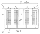
この開示には、可能な様々な多くの二重繊毛運動モーターが示されている。例えば、ただ二つのアクチュエーターに限定されない。多数のアクチュエーターの解決策も可能である。図8は、4個のアクチュエーターを有する電気機械式モーターの一実施態様を示す。この実施態様においては、アクチュエーターは電気的に二対になって接続され、上述の運動形態を与えている。協働するアクチュエーターは、互いに対してどんな形態も取りうるが、好ましくは意図された使用例に応じて選択される。この実施態様においては、4個のすべてのアクチュエーターが、直線上に並んでいる。しかし、異なる二次元位置に設けられたアクチュエーターの配置も可能である。異なるグループのアクチュエーターの対が互いに位相を異ならせて動作している時は、より滑らかな運動が得られる。 In this disclosure, a number of possible dual ciliary motors are shown. For example, it is not limited to just two actuators. Numerous actuator solutions are possible. FIG. 8 shows one embodiment of an electromechanical motor having four actuators. In this embodiment, the actuators are electrically connected in two pairs to provide the motion pattern described above. The cooperating actuators can take any form relative to each other, but are preferably selected depending on the intended use case. In this embodiment, all four actuators are arranged in a straight line. However, it is also possible to arrange actuators provided at different two-dimensional positions. When different groups of actuator pairs are operating out of phase with each other, a smoother motion is obtained.
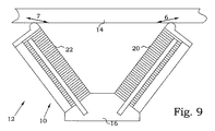
上の実施態様においては、アクチュエーターは、物体の相互作用面に対して直交するように示されている。上に述べたように、この配置は負荷の点で利点がある。しかし、他の応用では、例えば負荷が小さい場合には、その他の幾何学的形状も可能である。図9の実施態様は、非平行の二つのアクチュエーターを有する電気機械式モーターを示し、これらのアクチュエーターはさらに相互作用面13に対して直交していない。このようにして、接触エリヤ34、35の運動方向6,7と駆動方向4との間の傾斜角度を決めるための幾何学的デザインを利用することが可能である。
In the above embodiment, the actuator is shown orthogonal to the interaction surface of the object. As mentioned above, this arrangement is advantageous in terms of load. However, in other applications, other geometric shapes are possible, for example when the load is small. The embodiment of FIG. 9 shows an electromechanical motor with two non-parallel actuators, which are also not orthogonal to the
一対以上のアクチュエーターにアクセスできることで、ひとつ以上の方向の運動を得ることが可能である。一対のアクチュエーターは物体を一方向に駆動するのに使い、他の対のアクチュエーターを物体のそれと交差する方向に移動するのに使うことができる。ユニモルフはその場合目的の駆動方向に整合させる。 Having access to one or more actuators allows movement in one or more directions. A pair of actuators can be used to drive an object in one direction, and another pair of actuators can be used to move in a direction intersecting that of the object. The unimorph is then aligned with the desired drive direction.
二次元運動を得る他の可能性は、バイモルフ構造を持つアクチュエーターを交差方向に設けることである。このような実施態様は図10に示されている。各アクチュエーターの能動体積部は、交差する方向2に向いた二つの能動体積部に分割されている。能動体積部の各パートは、別々の電気信号により励起されるように設けられる。もし、信号が異なれば、アクチュエーターが交差する方向2に曲がる。電気信号を調節することにより、駆動方向に交差する方向の運動が可能となる。 Another possibility for obtaining a two-dimensional movement is to provide an actuator with a bimorph structure in the cross direction. Such an embodiment is shown in FIG. The active volume of each actuator is divided into two active volumes facing in the intersecting direction 2. Each part of the active volume is provided to be excited by a separate electrical signal. If the signals are different, the actuator bends in the direction 2 that intersects. By adjusting the electrical signal, movement in a direction crossing the driving direction is possible.
上に説明した実施態様は、この発明の幾つかの例示であると理解すべきである。当業者は、この発明の範囲から外れることなくこれらの実施態様に対して様々な修正、結合又は変更ができることを理解するであろう。特に、異なる実施態様における異なる部分の解決は、技術的に可能ならば他の組み合わせ形態においてもできる。この発明の範囲は添付された請求の範囲により決められる。 It should be understood that the embodiments described above are several examples of the present invention. Those skilled in the art will appreciate that various modifications, combinations or changes can be made to these embodiments without departing from the scope of the invention. In particular, the solution of the different parts in the different embodiments can also be in other combinations if technically possible. The scope of the invention is determined by the appended claims.
Claims (6)
駆動方向(4)に変位を起こさせるように、該アクチュエーターアセンブリ(12)により作用される物体(14)とを有する電気機械式モーター(10)であって、
該アクチュエーターアセンブリ(12)は、アクチュエーター基台(16)と第一アクチュエーター(20)と第二アクチュエーター(22)とを有し、
該第一アクチュエーター(20)は、機械的に単一の取付部により取付けられ、
該第一アクチュエーター(20)の単一の取付部(24)は、該アクチュエーター基台(16)に対する第一の取付部(24)であり、該第一取付部(24)は、該第一アクチュエーター(20)の第一端(25)に設けられており、
該第一アクチュエーター(20)は、該第一アクチュエーター(20)の第二端(31)を成す第一の相互作用部(30)を有し、該第一アクチュエーター(20)の第二端(31)は、該第一アクチュエーター(20)の第一端(25)とアクチュエーター方向(5)において反対側にあり、
該第二アクチュエーター(22)は機械的に単一取付部により取付けられ、
該第二アクチュエーター(22)の単一の取付部は、該アクチュエーター基台(16)に対する第二の取付部(26)であり、該第二取付部(26)は、該第二アクチュエーター(22)の第一端(27)に設けられており、
該第二アクチュエーター(22)は、該第二アクチュエーター(22)の第二端(33)を成す第二の相互作用部(32)を有し、該第二アクチュエーター(22)の第二端(33)は、該第二アクチュエーター(22)の第一端(27)とアクチュエーター方向(5)において反対側にあり、
該アクチュエーター方向(5)は、駆動方向(4)と交差しており、
該第一相互作用部(30)と該第二相互作用部(32)は、夫々の接触エリヤ(34、35)により該物体(14)の相互作用面(13)と相互作用するように配置された電気機械式モーター(10)において、
該第一アクチュエーター(20)と第二アクチュエーター(22)は、夫々が、該第一アクチュエーター(20)と第二アクチュエーター(22)の夫々の第一端(25,27)と該第二端(31、33)との間に配置された電気機械的材料を有する部材(36、38)を有しており、
電気機械的材料を有する該部材(36,38)の各々が、夫々に加えられる単一の電気信号の応答として各接触エリヤ(34,35)の1次元の前後運動(6,7)を起こすように配置され、
該各1次元の前後運動(6,7)は該アクチュエーター方向(5)に対しても、該駆動方向(4)に対してもさらに互いに対しても交差するようにされ、
電気機械的材料を有する該部材(36,38)の各々が、これに加えられる単一の電気信号に応じて寸法変化を起こす能動体積部(40、42)と、該アクチュエーター方向に沿って該各能動体積部(40,42)に機械的に取付られた受動体積部(44、46)とを有しており、
該第一アクチュエーター(20)の能動体積部(40)は、該駆動方向(4)に見て、該第一アクチュエーター(20)の該受動体積部(44)の前方に位置しており、
該第二アクチュエーター(22)の能動体積部(42)は、該駆動方向(4)に見て、該第二アクチュエーター(22)の該受動体積部(46)の後方に位置しており、
該第一相互作用部(30)と該第二相互作用部(32)が、これら相互作用部の各々が取付けられた該各アクチュエーター(20、22)の外に該駆動方向(4)に沿う方向に延出する延出部(37、39)を有し、
該第一相互作用部(30)と該第二相互作用部(32)の該それぞれの接触エリヤ(34、35)が、該延出部(37、39)に設けられ、
該第一相互作用部(30)の接触エリヤ(34)が、該駆動方向(4)と直交する交差方向(2)において該第二相互作用部(32)の接触エリヤ(35)と整合している
ことを特徴とする電気機械式モーター(10)。 An actuator assembly (12);
An electromechanical motor (10) having an object (14) acted on by the actuator assembly (12) to cause displacement in a driving direction (4),
The actuator assembly (12) has an actuator base (16), a first actuator (20), and a second actuator (22),
The first actuator (20) is mechanically attached by a single attachment,
The single attachment portion (24) of the first actuator (20) is a first attachment portion (24) to the actuator base (16), and the first attachment portion (24) is the first attachment portion (24). Provided at the first end (25) of the actuator (20);
The first actuator (20) has a first interaction portion (30) that forms a second end (31) of the first actuator (20), and the second end ( 31) is opposite the first end (25) of the first actuator (20) in the actuator direction (5);
The second actuator (22) is mechanically attached by a single attachment;
The single mounting portion of the second actuator (22) is a second mounting portion (26) for the actuator base (16), and the second mounting portion (26) is the second actuator (22). ) At the first end (27),
The second actuator (22) has a second interaction portion (32) that forms a second end (33) of the second actuator (22), and the second end ( 33) is opposite the first end (27) of the second actuator (22) in the actuator direction (5);
The actuator direction (5) intersects the drive direction (4),
The first interaction part (30) and the second interaction part (32) are arranged to interact with the interaction surface (13) of the object (14) by respective contact areas (34, 35). In an electromechanical motor (10)
The first actuator (20) and the second actuator (22) are respectively connected to the first end (25, 27) and the second end (of the first actuator (20) and the second actuator (22)). 31, 33) has a section member that have a electromechanical material (36, 38) disposed between,
Each of the member having an electromechanical material (36, 38) is one-dimensional longitudinal movement of each contact Elijah in response that was added to the respective single electrical signal (34, 35) (6,7) Arranged to cause
Each one-dimensional back-and-forth motion (6, 7) is made to intersect the actuator direction (5), the drive direction (4) and also to each other,
Each of the members (36, 38) having an electromechanical material has an active volume (40, 42) that undergoes a dimensional change in response to a single electrical signal applied thereto, along the actuator direction. A passive volume (44, 46) mechanically attached to each active volume (40, 42);
The active volume (40) of the first actuator (20) is located in front of the passive volume (44) of the first actuator (20) when viewed in the driving direction (4);
The active volume (42) of the second actuator (22) is located behind the passive volume (46) of the second actuator (22) when viewed in the driving direction (4) ;
The first interaction portion (30) and the second interaction portion (32) extend along the driving direction (4) outside the actuators (20, 22) to which the interaction portions are attached. Extending portions (37, 39) extending in the direction,
The respective contact areas (34, 35) of the first interaction part (30) and the second interaction part (32) are provided in the extension part (37, 39),
The contact area (34) of the first interaction part (30) is aligned with the contact area (35) of the second interaction part (32) in a cross direction (2) perpendicular to the drive direction (4). An electromechanical motor (10) characterized in that
該電極(41,43)は、
該能動体積部(40、42)に取付けられた受動体積部(44、46)から離れる方に向かう能動体積部(40、42)の面(51)と
該能動体積部(40、42)の該駆動方向(4)に沿う面(50)のうちの少なくとも一つの外へ延びていることを特徴とする請求項1に記載の電気機械式モーター。 At least one of the active volume (40) of the first actuator (20) and the active volume (42) of the second actuator (22) is activated to excite the active volume (40, 42). Having electrodes (41, 43) embedded in the volume (40, 42);
The electrodes (41, 43) are
The surface (51) of the active volume (40, 42) going away from the passive volume (44, 46) attached to the active volume (40, 42) and the active volume (40, 42) Electromechanical motor according to claim 1, characterized in that it extends out of at least one of the faces (50) along the drive direction (4).
該電気機械式モーター(10)に接続され、電気機械的材料を有する該部材(36,38)を励起するための少なくとも二つの異なる電気信号を与えるようにされた電源(99)とを有する電気機械式モーターシステム(1)。 The electromechanical motor (10) according to one paragraph to any one of claims 1 to 4,
A power source (99) connected to the electromechanical motor (10) and adapted to provide at least two different electrical signals for exciting the members (36, 38) having electromechanical material Electromechanical motor system (1).
該第一相互作用部(30)に取付られた電気機械的材料を有する部材(36)を励起するための第一の電気信号を与えるステップ(210)と、
該第二相互作用部(32)に取付られた電気機械的材料を有する部材(38)を励起するための第二の電気信号を与えるステップ(212)とを有しており、
該第一の電気信号は該第二の電気信号と異なっており、
該第一の電気信号と該第二の電気信号は、駆動の間、該第一相互作用部(30)と該第二相互作用部(32)の少なくとも一つが該物体(14)と接触せしめる(218)ようにされ、
電気機械的材料を有する該部材(36、38)の各々が、これらに加えられる前記第一の及び第二の電気信号に応じて寸法変化を起こす能動体積部(40、42)と、該アクチュエーター方向(5)に沿って該各能動部(40、42)に機械的に取り付けられた受動堆積部(44、46)とを有しており、
該第一の電気信号は、該第一相互作用部(30)の電気機械的材料を有する該部材(36)が、該第一相互作用部(30)の接触エリヤ(34)を、駆動方向(4)と交差するが直交しない、第一の1次元の前後運動方向(6)に運動させ(214)、該駆動方向(4)は、該第一相互作用部(30)と該第二相互作用部(32)に対する物体(14)の所期の前進移動方向であり、
該第二の電気信号は、該第二相互作用部(32)の電気機械的材料を有する該部材(38)が、該第二相互作用部(30)の接触エリヤ(35)を、駆動方向(4)と交差する第二の1次元の前後運動方向(7)に運動させ(216)、該第二の1次元の前後運動方向(7)は、該第一の1次元の前後運動方向(6)と交差し、
該第一相互作用部(30)の接触エリヤ(34)が、該駆動方向(4)と直交する交差方向(2)において該第二相互作用部(32)の接触エリヤ(35)と整合している
ことを特徴とする、
電気機械式モーター(10)を駆動する方法。 A method of driving an electromechanical motor (10) having a first interaction part (30) and a second interaction part (32) arranged to interact with an object (14), the method Is
A step (210) providing a first electrical signal for exciting said first interaction portion of section member that have a electromechanical material the attached (30) (36),
Has a step (212) providing a second electrical signal for exciting said second interaction portion (32) having a mounted electric mechanical material that section member (38),
The first electrical signal is different from the second electrical signal;
The first electrical signal and the second electrical signal cause at least one of the first interaction portion (30) and the second interaction portion (32) to contact the object (14) during driving. (218)
Each of the members (36, 38) having electromechanical material has an active volume (40, 42) that undergoes a dimensional change in response to the first and second electrical signals applied thereto, and the actuator A passive deposition portion (44, 46) mechanically attached to each active portion (40, 42) along direction (5);
The first electrical signal is generated by the member (36) having the electromechanical material of the first interaction part (30) driving the contact area (34) of the first interaction part (30). Moving in a first one-dimensional back-and-forth motion direction (6) that intersects the direction (4) but is not orthogonal (214), the drive direction (4) is connected to the first interaction part (30) and the first direction The desired forward movement direction of the object (14) relative to the two interaction part (32);
The second electrical signal is generated by the member (38) having the electromechanical material of the second interaction part (32) driving the contact area (35) of the second interaction part (30). The second one-dimensional back-and-forth motion direction (7) intersects the direction (4) (216) and the second one-dimensional back-and-forth motion direction (7) is the first one-dimensional back-and-forth motion. Intersect direction (6) ,
The contact area (34) of the first interaction part (30) is aligned with the contact area (35) of the second interaction part (32) in a cross direction (2) perpendicular to the drive direction (4). It is characterized by
A method of driving an electromechanical motor (10).
Applications Claiming Priority (1)
| Application Number | Priority Date | Filing Date | Title |
|---|---|---|---|
| PCT/EP2009/057735 WO2010149199A1 (en) | 2009-06-22 | 2009-06-22 | Electromechanical motor |
Publications (2)
| Publication Number | Publication Date |
|---|---|
| JP2012531177A JP2012531177A (en) | 2012-12-06 |
| JP5740397B2 true JP5740397B2 (en) | 2015-06-24 |
Family
ID=41666431
Family Applications (1)
| Application Number | Title | Priority Date | Filing Date |
|---|---|---|---|
| JP2012515363A Expired - Fee Related JP5740397B2 (en) | 2009-06-22 | 2009-06-22 | Electromechanical motor |
Country Status (4)
| Country | Link |
|---|---|
| US (1) | US8912708B2 (en) |
| JP (1) | JP5740397B2 (en) |
| KR (1) | KR20120112354A (en) |
| WO (1) | WO2010149199A1 (en) |
Families Citing this family (3)
| Publication number | Priority date | Publication date | Assignee | Title |
|---|---|---|---|---|
| DE112010006073T5 (en) * | 2010-12-20 | 2013-10-10 | Piezomotor Uppsala Ab | Electromechanical motor |
| US10777730B2 (en) * | 2017-12-26 | 2020-09-15 | Santosh Kumar BEHERA | Scalable piezoelectric linear actuator |
| DE102018212897A1 (en) * | 2018-08-02 | 2020-02-06 | Zf Friedrichshafen Ag | Ciliary connector |
Family Cites Families (17)
| Publication number | Priority date | Publication date | Assignee | Title |
|---|---|---|---|---|
| US4769570A (en) * | 1986-04-07 | 1988-09-06 | Toshiba Ceramics Co., Ltd. | Piezo-electric device |
| JPH044775A (en) | 1990-04-20 | 1992-01-09 | Toyota Central Res & Dev Lab Inc | Moving device for article |
| US6392329B1 (en) | 1999-10-12 | 2002-05-21 | Face International Corp. | Piezoelectric vibrating apparatus |
| IL137206A0 (en) * | 1999-10-31 | 2001-07-24 | Nanomotion Ltd | Piezoelectric motors and motor driving configurations |
| US6307301B1 (en) * | 2000-02-02 | 2001-10-23 | The Boeing Company | Buckling resistant piezoelectric actuator |
| GB2369489B (en) * | 2000-11-23 | 2004-03-10 | Khaled Karrai | Inertial rotation device |
| JP3830027B2 (en) | 2001-08-23 | 2006-10-04 | セイコーエプソン株式会社 | Wire actuator |
| US6798117B2 (en) * | 2002-07-10 | 2004-09-28 | Piezomotor Uppsala Ab | Fine control of electromechanical motors |
| US7061158B2 (en) * | 2002-07-25 | 2006-06-13 | Nanomotion Ltd. | High resolution piezoelectric motor |
| JP4062692B2 (en) | 2003-03-13 | 2008-03-19 | 東レエンジニアリング株式会社 | Walking motion drive unit and alignment apparatus using the same |
| JP4723199B2 (en) | 2003-06-19 | 2011-07-13 | 日本碍子株式会社 | Cylindrical piezoelectric actuator, cylindrical piezoelectric actuator array, and manufacturing method |
| JP4393180B2 (en) | 2003-12-15 | 2010-01-06 | Thk株式会社 | Single axis actuator |
| US7439652B2 (en) * | 2004-02-25 | 2008-10-21 | Nanomotion Ltd. | Multidirectional piezoelectric motor configuration |
| JP2006332616A (en) | 2005-04-28 | 2006-12-07 | Brother Ind Ltd | Method for manufacturing piezoelectric actuator |
| JP3824627B1 (en) | 2005-11-24 | 2006-09-20 | 株式会社キンセイ産業 | Method for melting waste asbestos |
| US7420321B2 (en) * | 2006-03-03 | 2008-09-02 | Piezomotor Uppsala Ab | Heat efficient micromotor |
| US7355325B2 (en) * | 2006-06-15 | 2008-04-08 | Piezomotor Uppsala Ab | Wide frequency range electromechanical actuator |
-
2009
- 2009-06-22 JP JP2012515363A patent/JP5740397B2/en not_active Expired - Fee Related
- 2009-06-22 US US13/379,415 patent/US8912708B2/en not_active Expired - Fee Related
- 2009-06-22 WO PCT/EP2009/057735 patent/WO2010149199A1/en not_active Ceased
- 2009-06-22 KR KR1020127001437A patent/KR20120112354A/en not_active Ceased
Also Published As
| Publication number | Publication date |
|---|---|
| KR20120112354A (en) | 2012-10-11 |
| WO2010149199A1 (en) | 2010-12-29 |
| US20120098468A1 (en) | 2012-04-26 |
| JP2012531177A (en) | 2012-12-06 |
| US8912708B2 (en) | 2014-12-16 |
Similar Documents
| Publication | Publication Date | Title |
|---|---|---|
| JP5114476B2 (en) | Wide frequency electromechanical actuator | |
| US6747394B2 (en) | Near-resonance electromechanical motor | |
| US6967430B2 (en) | Flat resonating electromechanical drive unit | |
| JP5730765B2 (en) | Quasi-resonant drive system and method | |
| US7157830B2 (en) | Near-resonance wide-range operating electromechanical motor | |
| JP2011217595A (en) | Vibration wave driving apparatus and method for manufacturing vibrating body thereof | |
| JP4452275B2 (en) | Piezoelectric mechanical drive | |
| JP4188967B2 (en) | Piezoelectric linear motor having displacement magnifying means | |
| Dong et al. | Piezoelectric ring-morph actuators for valve application | |
| KR100559199B1 (en) | Double electromechanical elements | |
| JP5740397B2 (en) | Electromechanical motor | |
| US7161278B2 (en) | Peristaltic electromechanical actuator | |
| US20110227454A1 (en) | Vibrator in vibration type driving apparatus and manufacturing method thereof | |
| US20140210311A1 (en) | Noiseless Electromechanical Motor | |
| WO2012041370A1 (en) | Electromechanical actuator | |
| JP3892183B2 (en) | Piezoelectric actuator | |
| JP2005102369A (en) | Drive device |
Legal Events
| Date | Code | Title | Description |
|---|---|---|---|
| A131 | Notification of reasons for refusal |
Free format text: JAPANESE INTERMEDIATE CODE: A131 Effective date: 20130903 |
|
| A521 | Request for written amendment filed |
Free format text: JAPANESE INTERMEDIATE CODE: A523 Effective date: 20131125 |
|
| A131 | Notification of reasons for refusal |
Free format text: JAPANESE INTERMEDIATE CODE: A131 Effective date: 20140507 |
|
| A601 | Written request for extension of time |
Free format text: JAPANESE INTERMEDIATE CODE: A601 Effective date: 20140728 |
|
| A602 | Written permission of extension of time |
Free format text: JAPANESE INTERMEDIATE CODE: A602 Effective date: 20140804 |
|
| A521 | Request for written amendment filed |
Free format text: JAPANESE INTERMEDIATE CODE: A523 Effective date: 20141030 |
|
| TRDD | Decision of grant or rejection written | ||
| A01 | Written decision to grant a patent or to grant a registration (utility model) |
Free format text: JAPANESE INTERMEDIATE CODE: A01 Effective date: 20150407 |
|
| A61 | First payment of annual fees (during grant procedure) |
Free format text: JAPANESE INTERMEDIATE CODE: A61 Effective date: 20150427 |
|
| R150 | Certificate of patent or registration of utility model |
Ref document number: 5740397 Country of ref document: JP Free format text: JAPANESE INTERMEDIATE CODE: R150 |
|
| R250 | Receipt of annual fees |
Free format text: JAPANESE INTERMEDIATE CODE: R250 |
|
| R250 | Receipt of annual fees |
Free format text: JAPANESE INTERMEDIATE CODE: R250 |
|
| R250 | Receipt of annual fees |
Free format text: JAPANESE INTERMEDIATE CODE: R250 |
|
| R250 | Receipt of annual fees |
Free format text: JAPANESE INTERMEDIATE CODE: R250 |
|
| R250 | Receipt of annual fees |
Free format text: JAPANESE INTERMEDIATE CODE: R250 |
|
| R250 | Receipt of annual fees |
Free format text: JAPANESE INTERMEDIATE CODE: R250 |
|
| LAPS | Cancellation because of no payment of annual fees |