JP5730765B2 - Quasi-resonant drive system and method - Google Patents
Quasi-resonant drive system and method Download PDFInfo
- Publication number
- JP5730765B2 JP5730765B2 JP2011523929A JP2011523929A JP5730765B2 JP 5730765 B2 JP5730765 B2 JP 5730765B2 JP 2011523929 A JP2011523929 A JP 2011523929A JP 2011523929 A JP2011523929 A JP 2011523929A JP 5730765 B2 JP5730765 B2 JP 5730765B2
- Authority
- JP
- Japan
- Prior art keywords
- vibration
- piezoelectric
- bending modes
- pair
- directions
- Prior art date
- Legal status (The legal status is an assumption and is not a legal conclusion. Google has not performed a legal analysis and makes no representation as to the accuracy of the status listed.)
- Active
Links
- 238000000034 method Methods 0.000 title claims description 29
- 238000005452 bending Methods 0.000 claims description 111
- 230000010363 phase shift Effects 0.000 claims description 26
- 230000003287 optical effect Effects 0.000 claims description 21
- 238000004519 manufacturing process Methods 0.000 claims description 12
- 230000010355 oscillation Effects 0.000 claims description 10
- 230000008878 coupling Effects 0.000 claims description 8
- 238000010168 coupling process Methods 0.000 claims description 8
- 238000005859 coupling reaction Methods 0.000 claims description 8
- 239000010410 layer Substances 0.000 description 47
- 230000008859 change Effects 0.000 description 8
- 230000007423 decrease Effects 0.000 description 8
- 230000008901 benefit Effects 0.000 description 5
- 230000010287 polarization Effects 0.000 description 5
- 230000008569 process Effects 0.000 description 5
- 238000006073 displacement reaction Methods 0.000 description 4
- 239000002184 metal Substances 0.000 description 4
- 230000036316 preload Effects 0.000 description 4
- 238000010586 diagram Methods 0.000 description 3
- 239000000463 material Substances 0.000 description 3
- MCMNRKCIXSYSNV-UHFFFAOYSA-N Zirconium dioxide Chemical compound O=[Zr]=O MCMNRKCIXSYSNV-UHFFFAOYSA-N 0.000 description 2
- 230000007613 environmental effect Effects 0.000 description 2
- 230000004048 modification Effects 0.000 description 2
- 238000012986 modification Methods 0.000 description 2
- 230000007935 neutral effect Effects 0.000 description 2
- 230000000704 physical effect Effects 0.000 description 2
- 239000002356 single layer Substances 0.000 description 2
- 230000003187 abdominal effect Effects 0.000 description 1
- 239000000853 adhesive Substances 0.000 description 1
- 230000001070 adhesive effect Effects 0.000 description 1
- PNEYBMLMFCGWSK-UHFFFAOYSA-N aluminium oxide Inorganic materials [O-2].[O-2].[O-2].[Al+3].[Al+3] PNEYBMLMFCGWSK-UHFFFAOYSA-N 0.000 description 1
- 230000003321 amplification Effects 0.000 description 1
- 239000003990 capacitor Substances 0.000 description 1
- 239000000919 ceramic Substances 0.000 description 1
- 229910010293 ceramic material Inorganic materials 0.000 description 1
- 230000001276 controlling effect Effects 0.000 description 1
- 230000002596 correlated effect Effects 0.000 description 1
- 238000007599 discharging Methods 0.000 description 1
- 230000000694 effects Effects 0.000 description 1
- 238000005516 engineering process Methods 0.000 description 1
- 230000005284 excitation Effects 0.000 description 1
- 239000003292 glue Substances 0.000 description 1
- 230000007246 mechanism Effects 0.000 description 1
- 238000005459 micromachining Methods 0.000 description 1
- 238000003199 nucleic acid amplification method Methods 0.000 description 1
- 238000001259 photo etching Methods 0.000 description 1
- 230000003068 static effect Effects 0.000 description 1
- 239000000126 substance Substances 0.000 description 1
Images


Classifications
-
- H—ELECTRICITY
- H02—GENERATION; CONVERSION OR DISTRIBUTION OF ELECTRIC POWER
- H02N—ELECTRIC MACHINES NOT OTHERWISE PROVIDED FOR
- H02N2/00—Electric machines in general using piezoelectric effect, electrostriction or magnetostriction
- H02N2/02—Electric machines in general using piezoelectric effect, electrostriction or magnetostriction producing linear motion, e.g. actuators; Linear positioners ; Linear motors
- H02N2/026—Electric machines in general using piezoelectric effect, electrostriction or magnetostriction producing linear motion, e.g. actuators; Linear positioners ; Linear motors by pressing one or more vibrators against the driven body
-
- H—ELECTRICITY
- H02—GENERATION; CONVERSION OR DISTRIBUTION OF ELECTRIC POWER
- H02N—ELECTRIC MACHINES NOT OTHERWISE PROVIDED FOR
- H02N2/00—Electric machines in general using piezoelectric effect, electrostriction or magnetostriction
-
- H—ELECTRICITY
- H02—GENERATION; CONVERSION OR DISTRIBUTION OF ELECTRIC POWER
- H02N—ELECTRIC MACHINES NOT OTHERWISE PROVIDED FOR
- H02N2/00—Electric machines in general using piezoelectric effect, electrostriction or magnetostriction
- H02N2/0005—Electric machines in general using piezoelectric effect, electrostriction or magnetostriction producing non-specific motion; Details common to machines covered by H02N2/02 - H02N2/16
- H02N2/001—Driving devices, e.g. vibrators
- H02N2/0015—Driving devices, e.g. vibrators using only bending modes
-
- H—ELECTRICITY
- H02—GENERATION; CONVERSION OR DISTRIBUTION OF ELECTRIC POWER
- H02N—ELECTRIC MACHINES NOT OTHERWISE PROVIDED FOR
- H02N2/00—Electric machines in general using piezoelectric effect, electrostriction or magnetostriction
- H02N2/02—Electric machines in general using piezoelectric effect, electrostriction or magnetostriction producing linear motion, e.g. actuators; Linear positioners ; Linear motors
- H02N2/06—Drive circuits; Control arrangements or methods
- H02N2/062—Small signal circuits; Means for controlling position or derived quantities, e.g. for removing hysteresis
-
- H—ELECTRICITY
- H02—GENERATION; CONVERSION OR DISTRIBUTION OF ELECTRIC POWER
- H02N—ELECTRIC MACHINES NOT OTHERWISE PROVIDED FOR
- H02N2/00—Electric machines in general using piezoelectric effect, electrostriction or magnetostriction
- H02N2/02—Electric machines in general using piezoelectric effect, electrostriction or magnetostriction producing linear motion, e.g. actuators; Linear positioners ; Linear motors
- H02N2/06—Drive circuits; Control arrangements or methods
- H02N2/065—Large signal circuits, e.g. final stages
-
- H—ELECTRICITY
- H02—GENERATION; CONVERSION OR DISTRIBUTION OF ELECTRIC POWER
- H02N—ELECTRIC MACHINES NOT OTHERWISE PROVIDED FOR
- H02N2/00—Electric machines in general using piezoelectric effect, electrostriction or magnetostriction
- H02N2/10—Electric machines in general using piezoelectric effect, electrostriction or magnetostriction producing rotary motion, e.g. rotary motors
- H02N2/103—Electric machines in general using piezoelectric effect, electrostriction or magnetostriction producing rotary motion, e.g. rotary motors by pressing one or more vibrators against the rotor
-
- H—ELECTRICITY
- H02—GENERATION; CONVERSION OR DISTRIBUTION OF ELECTRIC POWER
- H02N—ELECTRIC MACHINES NOT OTHERWISE PROVIDED FOR
- H02N2/00—Electric machines in general using piezoelectric effect, electrostriction or magnetostriction
- H02N2/10—Electric machines in general using piezoelectric effect, electrostriction or magnetostriction producing rotary motion, e.g. rotary motors
- H02N2/14—Drive circuits; Control arrangements or methods
- H02N2/142—Small signal circuits; Means for controlling position or derived quantities, e.g. speed, torque, starting, stopping, reversing
-
- H—ELECTRICITY
- H02—GENERATION; CONVERSION OR DISTRIBUTION OF ELECTRIC POWER
- H02N—ELECTRIC MACHINES NOT OTHERWISE PROVIDED FOR
- H02N2/00—Electric machines in general using piezoelectric effect, electrostriction or magnetostriction
- H02N2/10—Electric machines in general using piezoelectric effect, electrostriction or magnetostriction producing rotary motion, e.g. rotary motors
- H02N2/14—Drive circuits; Control arrangements or methods
- H02N2/145—Large signal circuits, e.g. final stages
- H02N2/147—Multi-phase circuits
-
- H—ELECTRICITY
- H10—SEMICONDUCTOR DEVICES; ELECTRIC SOLID-STATE DEVICES NOT OTHERWISE PROVIDED FOR
- H10N—ELECTRIC SOLID-STATE DEVICES NOT OTHERWISE PROVIDED FOR
- H10N30/00—Piezoelectric or electrostrictive devices
-
- H—ELECTRICITY
- H10—SEMICONDUCTOR DEVICES; ELECTRIC SOLID-STATE DEVICES NOT OTHERWISE PROVIDED FOR
- H10N—ELECTRIC SOLID-STATE DEVICES NOT OTHERWISE PROVIDED FOR
- H10N30/00—Piezoelectric or electrostrictive devices
- H10N30/20—Piezoelectric or electrostrictive devices with electrical input and mechanical output, e.g. functioning as actuators or vibrators
-
- H—ELECTRICITY
- H10—SEMICONDUCTOR DEVICES; ELECTRIC SOLID-STATE DEVICES NOT OTHERWISE PROVIDED FOR
- H10N—ELECTRIC SOLID-STATE DEVICES NOT OTHERWISE PROVIDED FOR
- H10N30/00—Piezoelectric or electrostrictive devices
- H10N30/80—Constructional details
- H10N30/87—Electrodes or interconnections, e.g. leads or terminals
- H10N30/872—Connection electrodes of multilayer piezoelectric or electrostrictive devices, e.g. external electrodes
-
- Y—GENERAL TAGGING OF NEW TECHNOLOGICAL DEVELOPMENTS; GENERAL TAGGING OF CROSS-SECTIONAL TECHNOLOGIES SPANNING OVER SEVERAL SECTIONS OF THE IPC; TECHNICAL SUBJECTS COVERED BY FORMER USPC CROSS-REFERENCE ART COLLECTIONS [XRACs] AND DIGESTS
- Y10—TECHNICAL SUBJECTS COVERED BY FORMER USPC
- Y10T—TECHNICAL SUBJECTS COVERED BY FORMER US CLASSIFICATION
- Y10T29/00—Metal working
- Y10T29/42—Piezoelectric device making
Description
本願は、2008年8月18日出願の米国特許出願第12/228,943号の恩典を主張するものであって、該出願は参照により、その全体が本明細書に組み込まれる。 This application claims the benefit of US patent application Ser. No. 12 / 228,943, filed Aug. 18, 2008, which is hereby incorporated by reference in its entirety.
本発明は、概して、駆動システムおよびその方法に関し、より具体的には、準共振駆動システムおよびその方法に関する。 The present invention relates generally to drive systems and methods, and more particularly to quasi-resonant drive systems and methods.
圧電技術を使用した変換器は、ナノメートルスケールの精密な位置調節のために使用される。典型的には、圧電デバイスは、帯電および放電時、形状を変化させるコンデンサに形成されるセラミックを含む。これらの圧電デバイスは、その形状変化特性(すなわち、振動)によって、位置調節アクチュエータとして使用可能である。そのような圧電デバイスが、位置調節アクチュエータとして使用される場合、該形状変化は、該印加される電圧差にほぼ比例する。 Transducers using piezoelectric technology are used for precise positioning on the nanometer scale. Typically, a piezoelectric device includes a ceramic that is formed into a capacitor that changes shape during charging and discharging. These piezoelectric devices can be used as position adjusting actuators due to their shape change characteristics (ie, vibration). When such a piezoelectric device is used as a position adjustment actuator, the shape change is approximately proportional to the applied voltage difference.
超音波駆動装置は、これらの圧電生成振動を使用し、高速、高トルク、小型サイズ、および静動作の継続的移動をもたらす。例示的な先行技術の超音波駆動システムは、螺刻されたナットを支持するシリンダを含む。シリンダは4つの対称的に位置付けられた圧電変換器を含み、円形軌道において、±90度位相シフトを伴う超音波範囲内の第1の曲げモード共振周波数において、直交曲げモードのシリンダを同時に励起する。螺刻されたナットは、螺刻されたシャフトを直線的に移動させる螺刻されたシャフトを回転させるトルクを生成する第1の曲げモード共振周波数において、螺刻されたシャフトを周回する。 Ultrasonic drives use these piezoelectrically generated vibrations to provide high speed, high torque, small size, and continuous movement of static motion. An exemplary prior art ultrasonic drive system includes a cylinder that supports a threaded nut. The cylinder includes four symmetrically positioned piezoelectric transducers that simultaneously excite the orthogonal bending mode cylinder in a circular orbit at a first bending mode resonance frequency in the ultrasonic range with a ± 90 degree phase shift. . The threaded nut orbits the threaded shaft at a first bending mode resonance frequency that generates a torque that rotates the threaded shaft that linearly moves the threaded shaft.
多くの超音波駆動装置は、典型的には、100mm/sからさらには1000mm/sにもおよぶ範囲の速度で動作する。しかしながら、本速度は、画像センサおよび光学カメラシステムの精密な位置制御には高速過ぎる。画像センサおよびセンサのアルゴリズムは、動きが不安定かつステップ解像度が低いため、十分な品質で画像を撮像することができない。 Many ultrasonic drives typically operate at speeds ranging from 100 mm / s to even 1000 mm / s. However, this speed is too high for precise position control of image sensors and optical camera systems. The image sensor and the algorithm of the sensor cannot take an image with sufficient quality because the motion is unstable and the step resolution is low.
本発明の実施形態による、駆動システムは、ある構造および振動システムを含む。この構造は、可動要素に摩擦連結しかつ可動要素を少なくとも2つの方向のうちの1つに駆動するための少なくとも1つの点を有する。また、該構造は、異なる共振周波数をそれぞれ有する、少なくとも2つの曲げモードを有する。該振動システムは、該構造の曲げモードのそれぞれに対する振動周波数の、2つ以上の振動信号を印加する。該振動周波数は、共振周波数のうちの1つと実質的に同一である。該振動周波数において、該構造の曲げモードのうちの一方は、実質的に共振振動し、該構造の曲げモードの他方は、部分的に共振振動する。該振動システムは、2つ以上の印加される振動信号間の位相シフトを調節して、少なくとも2つの方向のうちのいずれに可動要素が移動されるかを制御する。 A drive system according to an embodiment of the invention includes a structure and a vibration system. The structure has at least one point for frictionally coupling the movable element and driving the movable element in one of at least two directions. The structure also has at least two bending modes, each having a different resonant frequency. The vibration system applies two or more vibration signals at vibration frequencies for each of the bending modes of the structure. The vibration frequency is substantially the same as one of the resonance frequencies. At the vibration frequency, one of the bending modes of the structure substantially resonates and the other of the bending modes of the structure partially resonates. The vibration system adjusts the phase shift between two or more applied vibration signals to control in which of the at least two directions the movable element is moved.
本発明の他の実施形態による、駆動システムを作製するための方法は、可動要素に摩擦連結しかつ可動要素を少なくとも2つの方向のうちの1つに駆動するための少なくとも1つの点を有する構造を提供する工程を含む。構造は、異なる共振周波数をそれぞれ有する、少なくとも2つの曲げモードを有する。2つ以上の振動周波数の振動信号を印加する振動システムは、該構造の曲げモードのそれぞれに連結される。該振動周波数は、共振周波数のうちの1つと実質的に同一である。該振動周波数において、該構造の曲げモードのうちの一方は、実質的に共振振動し、該構造の曲げモードの他方は、部分的に共振振動する。該振動システムは、2つ以上の印加される振動信号間の位相シフトを調節して、少なくとも2つの方向のうちのいずれに可動要素が移動されるかを制御する。 According to another embodiment of the present invention, a method for making a drive system includes a structure having at least one point for frictionally coupling to a movable element and driving the movable element in one of at least two directions. Providing a step. The structure has at least two bending modes, each having a different resonant frequency. A vibration system that applies vibration signals at two or more vibration frequencies is coupled to each of the bending modes of the structure. The vibration frequency is substantially the same as one of the resonance frequencies. At the vibration frequency, one of the bending modes of the structure substantially resonates and the other of the bending modes of the structure partially resonates. The vibration system adjusts the phase shift between two or more applied vibration signals to control in which of the at least two directions the movable element is moved.
本発明の他の実施形態による光学システムは、少なくとも1つの光学構成要素および少なくとも1つの駆動システムを含む。該駆動システムは、振動システムと、摩擦連結されて1つ以上の方向に光学構成要素を移動させる構造とを備える。該構造は、異なる共振周波数をそれぞれ有する、少なくとも2つの曲げモードを有する。該振動システムは、該構造の曲げモードのそれぞれに対する振動周波数の、2つ以上の振動信号を印加する。該振動周波数は、共振周波数のうちの1つと実質的に同一である。該振動周波数において、該構造の曲げモードのうちの一方は、実質的に共振振動し、該構造の曲げモードの他方は、部分的に共振振動する。該振動システムは、2つ以上の印加される振動信号間の位相シフトを調節して、少なくとも2つの方向のうちのいずれに可動要素が移動されるかを制御する。 An optical system according to another embodiment of the present invention includes at least one optical component and at least one drive system. The drive system includes a vibration system and a structure that is frictionally coupled to move the optical component in one or more directions. The structure has at least two bending modes, each having a different resonant frequency. The vibration system applies two or more vibration signals at vibration frequencies for each of the bending modes of the structure. The vibration frequency is substantially the same as one of the resonance frequencies. At the vibration frequency, one of the bending modes of the structure substantially resonates and the other of the bending modes of the structure partially resonates. The vibration system adjusts the phase shift between two or more applied vibration signals to control in which of the at least two directions the movable element is moved.
本発明は、より効果的かつ効率的な準共振駆動システムを提供することを含め、いくつかの利点をもたらす。一例にすぎないが、カメラにおけるオートフォーカスシステムおよびオートズームシステム等、種々の異なる用途において、準共振駆動システムを使用して、種々の異なる負荷を移動させることが可能である。
[本発明1001]
可動要素に摩擦連結しかつ可動要素を少なくとも2つの方向のうちの1つに駆動するための少なくとも1つの点を有し、異なる共振周波数をそれぞれ有する少なくとも2つの曲げモードを有する構造と、
前記構造の前記曲げモードのそれぞれに対する、前記共振周波数のうちの1つと実質的に同一である振動周波数の、2つ以上の振動信号を印加する振動システムと
を備える、駆動システムであって、
前記振動周波数において、前記構造の前記曲げモードの一方が、実質的に共振振動し、前記構造の前記曲げモードの他方が、部分的に共振振動し、前記振動システムが、前記2つ以上の印加される振動信号間の位相シフトを調節して、前記少なくとも2つの方向のいずれに前記可動要素が移動されるかを制御する、前記駆動システム。
[本発明1002]
前記構造が、非対称である、本発明1001のシステム。
[本発明1003]
前記少なくとも1つの点が、実質的に前記構造の波腹点である、本発明1001のシステム。
[本発明1004]
前記構造が、
特定の極性を確立するように分極され、かつ前記構造において対称的に設置されて、前記振動システムが前記2つ以上の振動信号のうちの少なくとも1つを印加した際に、前記構造における前記2つの曲げモードのうちの少なくとも1つを生成する、少なくとも2つの圧電領域
を備える、本発明1001のシステム。
[本発明1005]
前記構造が、
特定の極性を確立するように分極され、かつ前記構造において対称的に設置されて、前記振動システムが前記2つ以上の振動信号を印加した際に、前記構造において前記少なくとも2つの曲げモードを生成する、少なくとも4つの圧電領域
を備える、本発明1001のシステム。
[本発明1006]
前記圧電領域のうちの少なくとも2つが、前記圧電領域の少なくとも他の2つの間に配置される、本発明1005のシステム。
[本発明1007]
前記構造が、
2つ以上の圧電層と、
各電極対が1つ以上の前記圧電層の対向する側面に連結される、電極の2つ以上の対と
を備える、本発明1001のシステム。
[本発明1008]
部分的な共振で振動している前記曲げモードの他方が、前記構造が前記可動要素を駆動することができる前記少なくとも2つの方向のそれぞれと実質的に平行な方向に屈曲している、本発明1001のシステム。
[本発明1009]
共振振動している前記曲げモードの一方が、前記構造が前記可動要素を駆動することができる前記少なくとも2つの方向のそれぞれと実質的に平行な方向に屈曲している、本発明1001のシステム。
[本発明1010]
可動要素に摩擦連結しかつ可動要素を少なくとも2つの方向のうちの1つに駆動するための少なくとも1つの点を有し、異なる共振周波数をそれぞれ有する少なくとも2つの曲げモードを有する構造を提供する工程と、
前記構造の前記曲げモードのそれぞれに対する、前記共振周波数のうちの1つと実質的に同一である振動周波数の、2つ以上の振動信号を印加する振動システムを連結する工程と
を含む、駆動システムを作製するための方法であって、
前記振動周波数において、前記構造の前記曲げモードの一方が、実質的に共振振動し、前記構造の前記曲げモードの他方が、部分的に共振振動し、前記振動システムが、前記2つ以上の印加される振動信号間の位相シフトを調節して、前記少なくとも2つの方向のいずれに前記可動要素が移動されるかを制御する、前記方法。
[本発明1011]
前記構造が、非対称である、本発明1010の方法。
[本発明1012]
前記少なくとも1つの点が、実質的に前記構造の波腹点である、本発明1010の方法。
[本発明1013]
前記構造が、
特定の極性を確立するように分極され、かつ前記構造において対称的に設置されて、前記振動システムが前記2つ以上の振動信号のうちの少なくとも1つを印加した際に、前記構造における前記2つの曲げモードのうちの少なくとも1つを生成する、少なくとも2つの圧電領域
を備える、本発明1010の方法。
[本発明1014]
前記構造が、
特定の極性を確立するように分極され、かつ前記構造において対称的に設置されて、前記振動システムが前記2つ以上の振動信号を印加した際に、前記構造において前記少なくとも2つのモードを生成する、少なくとも4つの圧電領域
を備える、本発明1010の方法。
[本発明1015]
前記圧電領域のうちの少なくとも2つが、前記圧電領域の少なくとも他の2つの間に配置される、本発明1014の方法。
[本発明1016]
前記構造を提供する工程が、
2つ以上の圧電層を提供することと、
電極の2つ以上の対のそれぞれを、1つ以上の前記圧電層の対向する側面に連結することと
をさらに含む、本発明1010の方法。
[本発明1017]
部分的な共振で振動している前記曲げモードの他方が、前記構造が前記可動要素を駆動することができる前記少なくとも2つの方向のそれぞれと実質的に平行な方向に屈曲している、本発明1010の方法。
[本発明1018]
共振振動している、前記曲げモードの前記一方が、前記構造が前記可動要素を駆動することができる前記少なくとも2つの方向のそれぞれと実質的に平行な方向に屈曲している、本発明1010の方法。
[本発明1019]
少なくとも1つの光学構成要素と、
1つ以上の方向に前記少なくとも1つの光学構成要素を移動させるように摩擦連結された、ある構造および振動システムを備える少なくとも1つの駆動システムであって、前記構造が、少なくとも2つの曲げモードを有し、前記曲げモードのそれぞれが、異なる共振周波数を有し、前記振動システムが、前記構造の前記曲げモードのそれぞれに対する振動周波数の、2つ以上の振動信号を印加し、前記振動周波数が、前記共振周波数のうちの1つと実質的に同一であり、前記振動周波数において、前記構造の前記曲げモードの一方が、実質的に共振振動し、前記構造の前記曲げモードの他方が、部分的に共振振動し、前記振動システムが、前記2つ以上の印加される振動信号間の位相シフトを調節して、前記少なくとも2つの方向のいずれに前記光学要素が移動されるかを制御する、駆動システムと
を備える、光学システム。
[本発明1020]
前記構造が、非対称である、本発明1019のシステム。
[本発明1021]
前記少なくとも1つの点が、実質的に前記構造の波腹点である、本発明1019のシステム。
[本発明1022]
前記構造が、
特定の極性を確立するように分極され、かつ前記構造において対称的に設置されて、前記振動システムが前記2つ以上の振動信号のうちの少なくとも1つを印加した際に、前記構造における前記2つの曲げモードのうちの少なくとも1つを生成する、少なくとも2つの圧電領域
を備える、本発明1019のシステム。
[本発明1023]
前記構造が、
特定の極性を確立するように分極され、かつ前記構造において対称的に設置されて、前記振動システムが前記2つ以上の振動信号を印加した際に、前記構造において前記少なくとも2つの曲げモードを生成する、少なくとも4つの圧電領域
を備える、本発明1019のシステム。
[本発明1024]
前記圧電領域のうちの少なくとも2つが、前記圧電領域の少なくとも他の2つの間に配置される、本発明1023のシステム。
[本発明1025]
前記構造が、
2つ以上の圧電層と、
各電極対が1つ以上の前記圧電層の対向する側面に連結される、電極の2つ以上の対と
を備える、本発明1019のシステム。
[本発明1026]
部分的な共振で振動している前記曲げモードのうちの他方が、前記構造が前記可動要素を駆動することができる前記少なくとも2つの方向のそれぞれと実質的に平行な方向に屈曲している、本発明1019のシステム。
[本発明1027]
共振振動している前記曲げモードの前記一方が、前記構造が前記可動要素を駆動することができる前記少なくとも2つの方向のそれぞれと実質的に平行な方向に屈曲している、本発明1019のシステム。
The present invention provides several advantages, including providing a more effective and efficient quasi-resonant drive system. By way of example only, a quasi-resonant drive system can be used to move a variety of different loads in a variety of different applications, such as an autofocus system and an autozoom system in a camera.
[Invention 1001]
A structure having at least two bending modes each having a different resonant frequency, having at least one point for frictionally coupling to the movable element and driving the movable element in one of at least two directions;
A vibration system that applies two or more vibration signals at a vibration frequency that is substantially the same as one of the resonance frequencies for each of the bending modes of the structure;
A drive system comprising:
At the vibration frequency, one of the bending modes of the structure is substantially resonantly oscillated, the other of the bending modes of the structure is partially resonantly oscillated, and the vibration system is configured to apply the two or more applications. Adjusting the phase shift between generated vibration signals to control in which of the at least two directions the movable element is moved.
[Invention 1002]
The system of the present invention 1001, wherein the structure is asymmetric.
[Invention 1003]
The system of the present invention 1001, wherein the at least one point is substantially an antinode point of the structure.
[Invention 1004]
The structure is
Polarized to establish a specific polarity and placed symmetrically in the structure, when the vibration system applies at least one of the two or more vibration signals, the two in the structure At least two piezoelectric regions producing at least one of the two bending modes
The system of the invention 1001 comprising:
[Invention 1005]
The structure is
Polarized to establish a specific polarity and placed symmetrically in the structure to generate the at least two bending modes in the structure when the vibration system applies the two or more vibration signals At least four piezoelectric regions
The system of the invention 1001 comprising:
[Invention 1006]
The system of the present invention 1005, wherein at least two of the piezoelectric regions are disposed between at least two other of the piezoelectric regions.
[Invention 1007]
The structure is
Two or more piezoelectric layers;
Two or more pairs of electrodes, each electrode pair coupled to opposite sides of one or more of the piezoelectric layers;
The system of the invention 1001 comprising:
[Invention 1008]
The other of the bending modes oscillating with partial resonance is bent in a direction substantially parallel to each of the at least two directions in which the structure can drive the movable element. 1001 system.
[Invention 1009]
The system of the present invention 1001, wherein one of the bending modes in resonant oscillation is bent in a direction substantially parallel to each of the at least two directions in which the structure can drive the movable element.
[Invention 1010]
Providing a structure having at least two bending modes, each having a different resonant frequency, having at least one point for frictionally coupling to the movable element and driving the movable element in one of at least two directions When,
Coupling a vibration system that applies two or more vibration signals at a vibration frequency that is substantially the same as one of the resonance frequencies for each of the bending modes of the structure;
A method for making a drive system, comprising:
At the vibration frequency, one of the bending modes of the structure is substantially resonantly oscillated, the other of the bending modes of the structure is partially resonantly oscillated, and the vibration system is configured to apply the two or more applications. Adjusting the phase shift between the vibration signals to be controlled to control in which of the at least two directions the movable element is moved.
[Invention 1011]
The method of the present invention 1010, wherein the structure is asymmetric.
[Invention 1012]
The method of the present invention 1010, wherein the at least one point is substantially an antinode point of the structure.
[Invention 1013]
The structure is
Polarized to establish a specific polarity and placed symmetrically in the structure, when the vibration system applies at least one of the two or more vibration signals, the two in the structure At least two piezoelectric regions producing at least one of the two bending modes
The method of the invention 1010 comprising:
[Invention 1014]
The structure is
Polarized to establish a specific polarity and placed symmetrically in the structure to generate the at least two modes in the structure when the vibration system applies the two or more vibration signals , At least four piezoelectric regions
The method of the invention 1010 comprising:
[Invention 1015]
The method of the present invention 1014, wherein at least two of the piezoelectric regions are disposed between at least two other of the piezoelectric regions.
[Invention 1016]
Providing the structure comprises:
Providing two or more piezoelectric layers;
Coupling each of two or more pairs of electrodes to opposite sides of one or more of the piezoelectric layers;
The method of the present invention 1010 further comprising:
[Invention 1017]
The other of the bending modes oscillating with partial resonance is bent in a direction substantially parallel to each of the at least two directions in which the structure can drive the movable element. 1010 ways.
[Invention 1018]
The one of the bending modes in resonant oscillation is bent in a direction substantially parallel to each of the at least two directions in which the structure can drive the movable element. Method.
[Invention 1019]
At least one optical component;
At least one drive system comprising a structure and a vibration system frictionally coupled to move the at least one optical component in one or more directions, the structure having at least two bending modes; Each of the bending modes has a different resonant frequency, and the vibration system applies two or more vibration signals of a vibration frequency for each of the bending modes of the structure, Substantially the same as one of the resonance frequencies, at which the one of the bending modes of the structure is substantially resonantly oscillated and the other of the bending modes of the structure is partially resonant at the vibration frequency. Vibrate, and the vibration system adjusts a phase shift between the two or more applied vibration signals, so that the optical element in any of the at least two directions. There controls whether the movement, a drive system
An optical system comprising:
[Invention 1020]
The system of the present invention 1019, wherein the structure is asymmetric.
[Invention 1021]
The system of the present invention 1019, wherein the at least one point is substantially an antinode point of the structure.
[Invention 1022]
The structure is
Polarized to establish a specific polarity and placed symmetrically in the structure, when the vibration system applies at least one of the two or more vibration signals, the two in the structure At least two piezoelectric regions producing at least one of the two bending modes
The system of the present invention 1019, comprising:
[Invention 1023]
The structure is
Polarized to establish a specific polarity and placed symmetrically in the structure to generate the at least two bending modes in the structure when the vibration system applies the two or more vibration signals At least four piezoelectric regions
The system of the present invention 1019, comprising:
[Invention 1024]
The system of the present invention 1023, wherein at least two of the piezoelectric regions are disposed between at least two other of the piezoelectric regions.
[Invention 1025]
The structure is
Two or more piezoelectric layers;
Two or more pairs of electrodes, each electrode pair coupled to opposite sides of one or more of the piezoelectric layers;
The system of the present invention 1019, comprising:
[Invention 1026]
The other of the bending modes oscillating at partial resonance is bent in a direction substantially parallel to each of the at least two directions in which the structure can drive the movable element; The system of the invention 1019.
[Invention 1027]
The system of the invention 1019, wherein the one of the bending modes in resonant oscillation is bent in a direction substantially parallel to each of the at least two directions in which the structure can drive the movable element. .
詳細な説明
本発明の実施形態による、準共振駆動システム100が、図1Aに図示される。準共振駆動システム100は、アクチュエータシステム102および振動システム104を含むが、システム100は、他の種類および数のシステム、デバイス、および他の手法で接続される構成要素を含むことも可能である。本発明は、より効果的かつ効率的準共振駆動システムを提供する。
DETAILED DESCRIPTION A
より具体的に図1Aおよび図1Bを参照すると、アクチュエータシステム102は、2次元軌跡を生成し、一例にすぎないが光学レンズ等の可動負荷に摩擦連結し、少なくとも2つの対向する方向のいずれかに駆動するが、アクチュエータシステム102は、他の種類の軌跡を生成し、他の手法および他の場所に連結され、かつ他の方向に他の種類の負荷を移動させることも可能である。アクチュエータシステム102は、非対称の細長い構造103を含むが、アクチュエータシステム102は、他の形状および対称性を伴う、他の種類の構造を備えることも可能である。細長い構造103は、第1の共振周波数「fres1」を有する曲げモードを伴う奥行Dと、第2の共振周波数「fres2」を有する曲げモードを伴う高さHとを有する。高さHは、概して、第2の共振周波数「fres2」が、第1の共振周波数「fres1」より高くなるように、奥行Dを上回るが、該構造は、他の寸法を有することも可能である。一例にすぎないが、共振周波数に影響を及ぼす他の要因として、材料剛性、質量、ならびに内部電極の場所および配向が挙げられる。
More specifically, referring to FIGS. 1A and 1B, the
図2A〜図2Dを参照すると、細長い構造103は、ともに同時焼成される複数の並列圧電層を備えるが、細長い構造103は、単一層等の他の種類および数の層、他の種類および数の領域を備えることもでき、他の製造プロセスも使用可能である。細長い構造103のための圧電層はそれぞれ、約14マイクロメートル厚であるが、5マイクロメートル〜40マイクロメートルの厚さ等、層のそれぞれに対して、他の厚さを使用することも可能である。細長い構造103に対して複数の圧電層を使用することによって、細長い構造103のために単一圧電層が使用される際に使用され得るものよりも低い印加電圧が使用可能である。
2A-2D,
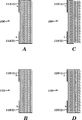
再び、図1Aを参照すると、細長い構造103は、4つの圧電領域106、108、110、および112と、電極114(1)および114(2)、電極116(1)および116(2)、電極118(1)および118(2)と、電極120(1)および120(2)を含むが、該構造は、他の数および種類の領域ならびにコネクタを伴う、他の数および種類の構造を備えることも可能である。一例にすぎないが、代替実施形態では、2つの圧電領域106および112のうちの1つと、圧電領域108および110のうちの1つは、駆動振幅を低減させるがそれ以外はアクチュエータシステムの動作を変更しない不活性領域とすることが可能であるが、活性領域と不活性領域の他の組み合わせも使用可能である。
Referring again to FIG. 1A, the
各圧電領域は、製造の際に分極することによって確立される極性を有し、正電極と負電極とをもたらす。圧電領域106、108、110、および112は、領域106に対して、「L」型電極114(1)が負(A-)であって、「L」型電極114(2)が正(A+)であって、領域112に対して、「L」型電極116(2)が負(B-)であって、「L」型電極116(1)が正(B+)であって、領域108に対して、「L」型電極118(1)が負(C-)であって、「L」型電極118(2)が正(C+)であって、領域110に対して、「L」型電極120(2)が負(D-)であって、「L」型電極120(1)が正(D+)であるように、製造の際に分極されるが、圧電領域は、他の様式でも形成可能である。細長い構造103では、圧電領域108および110は、図示されるように、相互に隣接し、外側圧電領域106と112との間に配置されるが、該構造は、他の構成において、他の数の圧電領域を有することも可能である。
Each piezoelectric region has a polarity established by polarization during manufacture, resulting in a positive electrode and a negative electrode.
図1A、図1B、および図2Aを参照すると、電極114(1)は、圧電領域106に対する圧電層のそれぞれの内部電極の1つに接続されるように連結および交互配置され、電極114(2)は、領域106に対する圧電層のそれぞれの対向する内部電極に接続されるように交互配置され、分極プロセスによって、電極114(1)を負とし、電極114(2)を正とするように領域106の極性を確立するが、他の場所における他の種類および数の接続も使用可能である。図1A、図1B、および図2Bを参照すると、電極116(1)は、圧電領域112に対する圧電層のそれぞれの内部電極の1つに接続されるように連結および交互配置され、電極116(2)は、領域112に対する圧電層のそれぞれの対向する内部電極に接続されるように交互配置され、分極プロセスによって、電極116(2)を負とし、電極116(1)を正とするように領域112の極性を確立するが、他の場所における他の種類および数の接続も使用可能である。図1A、図1B、および図2Cを参照すると、電極118(1)は、圧電領域108に対する圧電層のそれぞれの内部電極の1つに接続されるように連結および交互配置され、電極118(2)は、領域108に対する圧電層のそれぞれの対向する内部電極に接続されるように交互配置され、分極プロセスによって、電極118(1)を負とし、電極118(2)を正とするように領域108の極性を確立するが、他の場所における他の種類および数の接続も可能である。図1A、図1B、および図2Dを参照すると、電極120(1)は、圧電領域110に対する圧電層のそれぞれの内部電極の1つに接続されるように連結および交互配置され、電極120(2)は、領域110に対する圧電層のそれぞれの対向する内部電極に接続されるように交互配置され、分極プロセスによって、電極120(2)を負とし、電極120(1)を正とするように領域110の極性を確立するが、他の場所における他の種類および数の接続も可能である。
Referring to FIGS. 1A, 1B, and 2A, electrode 114 (1) is coupled and interleaved to be connected to one of the respective internal electrodes of the piezoelectric layer for
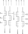
再び、図1Aを参照すると、振動システム104は一対のフルブリッジ駆動回路122(1)および122(2)を備え、そのそれぞれが電圧源Vddに連結され、かつ一例として図3に図示される超音波方形波振動信号を提供する4つの出力124(1)〜124(4)を有するが、一例として正弦波形状信号等の他の種類の信号を提供する他の数の出力を伴う、一例にすぎないがハーフブリッジ回路システム等の他の種類および数の駆動回路およびシステムも使用可能である。フルブリッジ駆動回路122(1)からの出力124(1)は、電極114(1)および116(1)に連結され、フルブリッジ駆動回路122(1)からの出力124(2)は、電極114(2)および116(2)に連結され、フルブリッジ駆動回路122(2)からの出力124(3)は、電極118(1)および120(1)に連結され、フルブリッジ駆動回路122(2)からの出力124(4)は、電極118(2)および120(2)に連結されるが、他の種類および数の接続も使用可能である。フルブリッジ駆動回路122(1)および122(2)を伴う、振動システム104の利点の1つは、圧電領域106、108、110、および112のそれぞれの正電極および負電極の間の実効電圧差が、供給電圧Vddの2倍であって、同一の供給電圧Vddを伴うハーフブリッジ回路と比較して、機械的出力を効果的に2倍にし、空間を節約するが、他の種類のシステムも使用可能である。フルブリッジ回路の構成要素および動作は、当業者に周知であるため、本明細書では、詳細に説明されない。
Referring again to FIG. 1A, the
次に、図1A〜図11Bを参照して、準共振駆動システム100の動作について説明する。上述のように、細長い構造103は、異なる共振周波数をそれぞれ有する、2つの曲げモード、モード1およびモード2を有する。これらの曲げモードのいずれの振動振幅も、印加される信号の振動周波数に依存する。振動システム104が、モード1の周波数「fres1」等の曲げモードの1つに対する共振周波数における振動信号を構造103の両曲げモードに印加すると、振動振幅は、その共振周波数で動作する曲げモードに対して完全に増幅され、部分的に共振動作する他方の曲げモードに対して部分的にのみ振幅される。振動システム104が、モード2の周波数等の曲げモードの他方に対する共振周波数「fres2」において、構造103の両曲げモードに信号を印加すると、振動振幅は、その共振周波数で動作する曲げモードに対して完全に増幅され、部分的に共振動作する他方の曲げモードに対して部分的にのみ振幅される。
Next, the operation of the
次に、本明細書において準共振とも称される、部分的共振について、詳細に説明する。fにおける強制励起下の典型的機械的システムでは、正規化振幅Aは、以下となる。
![]()
![]()
![]()
![]()
![]()
![]()
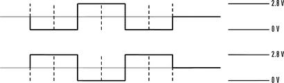
図1Aおよび3を参照すると、フルブリッジ駆動回路122(1)および122(2)の出力124(1)〜124(4)からの4つの振動信号が図示されているが、他の数および種類の信号も使用可能である。本実施例では、Vddは、2.8ボルトである。本実施例では、4つの振動信号は、出力124(1)〜124(4)から提供され、それぞれ、構造103の2つの曲げモードのうちの1つの共振周波数と実質的に同一の振動周波数を有する。さらに、出力124(1)〜124(2)からの振動信号は、2方向のうちの1つに、可動部材を移動させるために、振動システム104によって、出力124(3)〜124(4)からの振動信号に対して、約0度と90度との間で位相シフトされるが、位相シフトの他の範囲も使用可能である。なお、振動システム104は、出力124(1)〜124(2)と出力124(3)〜124(4)との間において、可動部材を反対方向に移動させるために、約-180度と-90度との間に位相シフトを調節するが、位相シフトの他の範囲も使用可能である。
Referring to FIGS. 1A and 3, four vibration signals from outputs 124 (1) -124 (4) of full bridge drive circuits 122 (1) and 122 (2) are illustrated, but other numbers and types These signals can also be used. In this example, V dd is 2.8 volts. In this example, four vibration signals are provided from outputs 124 (1) -124 (4), each having a vibration frequency substantially the same as the resonance frequency of one of the two bending modes of
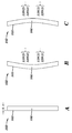
図3および図4A〜図4Cを参照すると、反対の極性の圧電領域106および112への異なる段階における出力124(1)〜124(2)からの振動信号の印加から生じる、曲げモードのうちの1つにおける構造103の運動が、図示される。図4(A)は、構造103の静止(全電極への電圧がゼロ)時である。図3の段階142に示されるように、出力124(1)と124(2)との間の電圧差が正である時、領域106は、長さが増加し、領域112は、長さが減少し、図4(b)に示されるように、構造103を屈曲させる。図3の段階140または144に示されるように、出力124(1)と124(2)との間の電圧差が負である時、領域106は、長さが減少し、領域112は、長さが増加し、図4(c)に示されるように、構造103を屈曲させる。出力124(1)からの振動信号は、電極114(1)(A-)および116(1)(B+)に印加され、出力124(2)からの振動信号は、電極114(2)(A+)および116(2)(B-)に印加される。
Referring to FIGS. 3 and 4A-4C, of the bending modes resulting from application of vibration signals from outputs 124 (1) -124 (2) at different stages to opposite polarity
図3および図5A〜図5Cを参照すると、反対の極性の圧電領域108および110への異なる段階における出力124(3)〜124(4)からの振動信号の印加から生じる、曲げモードの他方における構造103の運動が、図示される。図5(A)は、構造103の静止(全電極への電圧がゼロ)時である。図3の段階146または150に示されるように、出力124(3)と124(4)との間の電圧差が正である時、領域108は、長さが減少し、領域110は、長さが増加し、図5(b)に示されるように、構造103を屈曲させる。図3の段階148に示されるように、出力124(3)と124(4)との間の電圧差が負である時、領域108は、長さが増加し、領域110は、長さが減少し、図5(c)に示されるように、構造103を屈曲させる。出力124(3)からの振動信号は、電極118(1)(C-)および120(1)(D+)に印加され、出力124(4)からの振動信号は、電極118(2)(C+)および120(2)(D-)に印加される。
Referring to FIGS. 3 and 5A-5C, in the other of the bending modes resulting from the application of vibration signals from outputs 124 (3) -124 (4) at different stages to the opposite polarity
故に、上述のように、図3に図示されるようなフルブリッジ駆動回路122(1)および122(2)の出力124(1)〜124(4)からのアクチュエータシステム102への振動信号の印加は、アクチュエータシステム102に対して、楕円軌道の形状の2次元軌跡をもたらすが、アクチュエータシステム102は、他の直線的または成形軌跡が意図されることも可能である。上述のように、振動システム104は、アクチュエータシステム102が位相シフトの値に基づいて本楕円軌道経路において転動する方向を制御する。構造103の本曲げモードにおける準共振から生じる本楕円軌道のより狭小な部分は、アクチュエータシステム102がより小さくより精密なステップで可動要素を駆動させることを可能とする。
Thus, as described above, the application of vibration signals to the
アクチュエータシステム102のための本楕円軌道経路は、図6に図示され、2つの波節点128(1)および128(2)と、3つの波腹点、すなわち中央波腹点130および終端波腹点132(1)および132(2)とを有する。本実施例では、構造103の中央波腹点130を使用して、可動要素に摩擦連結しかつ可動要素を少なくとも2つの方向のうちの1つに駆動するが、終端波腹点132(1)および132(2)等の他の点も使用可能である。次に、一例にすぎないが、準共振駆動システム100を使用する、直線的および円形の運動システムの実施形態が、図7A〜図10Bを参照して説明される。
This elliptical orbit path for the
より具体的に図7A〜図7Bを参照すると、準共振駆動システム100を使用する、直線運動システム152が図示されるが、直線運動システムは、一例にすぎないが、駆動システム200および300等の他の種類の駆動システムも使用可能である。直線運動システム152は、図6を参照して説明されるように、中央波腹点において、構造103の中央接触パッド154を使用し、直線運動出力を生成する。構造103は、図6を参照して説明される波節点で、構造103の2つの接触点158(1)および158(2)において、ブラケット156によって糊で固着されるが、糊等の他の種類の接着剤または他の固着システムも使用可能である。予荷重力160は、バネ式機構162を通して、ブラケット156に印加されるが、他の種類の付勢システムも使用可能である。接触パッド154は、構造103の中央点にあって、方向166にリニア軸受168上を自由に移動する、スライダ164(1)に対して予荷重される。構造103が、共振または準共振モードで動作時、構造103は、円形または細長い楕円形状等の2次元軌跡を有し、方向166に沿ってスライダ164(1)を押動させる、正味摩擦力をもたらす。
Referring more specifically to FIGS. 7A-7B, a
スライダ164(1)は、リニア軸受168によって、方向166にのみ自由に移動するように制限されるが、他の構成も使用可能である。一例にすぎないが、リニア軸受168は、スライダ164(1)を方向166に自由に、かつ方向166にゼロではない最小の力で移動させる一方、依然として、スライダ164(1)の他の自由度を制約する、たわみガイドシステムと置換可能である。
The slider 164 (1) is restricted by the
図8A〜図8Bを参照すると、準共振駆動システム100を使用する、別の直線運動システム170が図示されるが、直線運動システムは、一例にすぎないが、駆動システム200および300等の他の種類の駆動システムも使用可能である。直線運動システム152におけるものと類似する、直線運動システム170における要素は、同様の参照番号を有し、ここでは再度説明されない。直線運動システム170は、本明細書に説明および図示されるものを除き、直線運動システム152と同一の構造および動作である。直線運動システム170は、図6を参照して説明されるように、終端波腹点において、構造103の終端接触パッド172(1)および172(2)を使用し、直線運動出力を生成する。接触パッド172(1)および172(2)は、構造103の終端点にあって、リニア軸受168上を方向166に自由に移動する、別のスライダ164(2)に対して予荷重される。構造103が、共振または準共振モードで動作すると、構造103は、円形または細長い楕円形状等の2次元軌跡を有し、方向166に沿ってスライダ164(2)を押動させる正味摩擦力をもたらす。2つの接触パッド172(1)および172(2)は、常に、構造103の対称性のため、同相で作用するであろう。
With reference to FIGS. 8A-8B, another
スライダ164(2)は、リニア軸受168によって、方向166にのみ自由に移動するように制限されるが、他の構成も使用可能である。一例にすぎないが、リニア軸受168は、方向166に自由に、かつ方向166にゼロではない最小の力で移動させる一方、依然として、スライダ164(2)の他の自由度を制約する、たわみガイドシステムと置換可能である。
The slider 164 (2) is limited by the
図9A〜図9Bを参照すると、準共振駆動システム100を使用する、円形運動システム172が図示されるが、円形運動システムは、他の種類の駆動システムも使用可能である。直線運動システム152におけるものに類似する、円形運動システム172における要素は、同様の参照番号を有し、ここでは再度説明されない。接触パッド154は、構造103の中央点にあって、回転軸受178(1)および対向する端部にある178(2)上に回転可能に着座する、シャフト177上の回転ホイール176(1)に対して予荷重される。構造103が、共振または準共振モードで動作すると、構造103は、円形または細長い楕円形状等の2次元軌跡を有し、方向182に沿って、ホイール176(1)を押動し、シャフト177を中心に回転させる、正味摩擦力をもたらす。
Referring to FIGS. 9A-9B, a
図10A〜図10Bを参照すると、準共振駆動システム100を使用する、円形運動システム184が図示されるが、円形運動システムは、他の種類の駆動システムも使用され得る。円形運動システム172のものに類似する、円形運動システム184における要素は、同様の参照番号を有し、ここでは再度説明されない。接触パッド172(1)および172(2)は、構造103の終端点にあって、対向する端部にある回転軸受178(1)および178(2)上に回転可能に着座する、シャフト177上の回転ホイール176(2)に対して予荷重される。構造103が、共振または準共振モードで動作すると、構造103は、円形または細長い楕円形状等の2次元軌跡を有し、方向182に沿って、ホイール176(2)を押動し、シャフト177を中心に回転せる、正味摩擦力をもたらす。
Referring to FIGS. 10A-10B, a
図11A〜図11Bを参照すると、これらのグラフは、駆動周波数(その共振周波数によって正規化される)の関数として、モード2の例示的な共振変位振幅および変位位相曲線を図示する。本実施例では、モード2の共振周波数196は、117KHzであって、機械的品質係数Qm2は、50である。なお、本実施例では、アクチュエータシステム102は、105KHz(モード1共振周波数)で駆動され、相対周波数は、点197における、105/117=〜0.9である。さらに、点197における振幅192は、点194におけるDCレベルまたは超低周波数における振幅の約5倍である。モード2の振幅192(意図される運動を実際に駆動する振動)は、多少増幅される。対照的に、モード1の振幅は、その共振周波数で動作するため、完全に増幅される。
Referring to FIGS. 11A-11B, these graphs illustrate an exemplary resonant displacement amplitude and displacement phase curve for
準共振駆動システム100の場合、比較的に高い機械的品質係数Qm2のため、モード2の変位と電圧信号との間の位相シフト193は、0°に近くなる(DCレベル195における位相に近い)。さらに、その共振周波数で動作するため、モード1の変位と電圧信号との間に-90°の機械的位相シフト191が存在する。したがって、モード1およびモード2の電気駆動信号のための位相差は、図6に図示されるような順方向または逆方向運動のための最適化楕円軌道を達成するためには、約0または180度である。本明細書に図示および説明されるように、準共振駆動システム100の動作時、両位相の品質係数および共振周波数は、最適化位相差に効果を有するため、モード1とモード2との間の電圧位相差角度は、典型的には、最適性能のために、0または180度から若干偏移されるように調節される。
For the
準共振駆動システム100を使用する、いくつかの利点がある。例えば、準共振駆動システム100は、従来技術の超音波モータシステムの非一貫性運動を克服する。モード1運動が、本発明において、Qm1によって完全に増幅されると、アクチュエータシステム102は、十分な垂直力差および十分な押動力を生成し、接触表面の非均一性、システムコンプライアンス、および駆動方向における運動に影響を及ぼし得る他の障害を克服する。モード2運動は、Qm2(例えば、50〜100)よりも低い増幅を有する(例えば、数回)。本実施例では、位相2運動は、作動方向に沿っており、20nmのDC運動の約5倍の100nmのステップをもたらす。105KHz動作の場合、理論的速度は、約10mm/sであるが、実際の速度は、摩擦損失によって、1秒当たり数ミリメートルとなる。準共振駆動システム100は、より低速度かつ高精度要件を有するオートズームおよびオートフォーカス用途にも使用可能である。
There are several advantages of using the
加えて、準共振駆動システム100は、モード2において、例えば、製造上の公差および環境変化による、共振周波数のずれの影響を受けにくい。先行技術のシステムの場合、モード1およびモード2の共振周波数の整合は、モータ性能に対して重要な意味を持つ。両モードが高Qmを有する場合、その共振周波数における若干の不整合は、モータ押動力および速度に有意な損失をもたらし得る。対照的に、準共振駆動システム100が、モード1の共振周波数とモード2の準共振で動作する場合、モード2の振動振幅および位相は、劇的に変化しない。結果として生じるモータ性能(すなわち、速度および押動力)は、より安定し、製造上の公差および環境変化に反応しない。その結果、準共振駆動システム100は、モード2からの共振周波数のずれの影響を受けにくい。
In addition, the
図12A〜図16Cを参照すると、本発明の他の実施形態による、準共振駆動システム200が図示される。準共振駆動システム200は、本明細書に説明および図示されるものを除き、準共振駆動システム100と同一構造および動作を有する。準共振駆動システム100におけるものと類似する、準共振駆動システム200における要素は、同様の参照番号を有し、ここでは再度説明されない。
Referring to FIGS. 12A-16C, a
より具体的に図12Aおよび図12Bを参照すると、アクチュエータシステム202は、2次元軌跡を生成し、一例にすぎないが光学レンズ等の可動負荷に摩擦連結し、光学レンズ等の可動負荷を、少なくとも2つの対向する方向のいずれかに駆動するが、アクチュエータシステム202は他の種類の軌跡を生成し、他の手法により他の場所で連結され、ならび他の方向に他の種類の負荷を移動させることもあり得る。アクチュエータシステム202は、非対称な細長い構造203を含むが、アクチュエータシステム202は、他の形状および対称性を伴う、他の種類の構造を備えることも可能である。細長い構造203は、第1の共振周波数「fres1」を有する曲げモードを伴う奥行Dと、第2の共振周波数「fres2」を有する曲げモードを伴う高さHとを有する。高さHは、概して、第2の共振周波数「fres2」が第1の共振周波数「fres1」より高くなるように、奥行Dを上回る。共振周波数に影響を及ぼす他の要因として、材料剛性、質量、ならびに内部電極の場所および配向が挙げられる。
More specifically, referring to FIGS. 12A and 12B, the
図13A〜図13Dを参照すると、細長い構造203は、ともに同時焼成される複数の並列圧電層を備えるが、細長い構造203は、単一層等の他の種類および数の層、他の種類および数の領域を備えることもでき、他の製造プロセスも使用可能である。細長い構造203の圧電層のそれぞれは、約14マイクロメートル厚であるが、5マイクロメートル〜40マイクロメートルの厚さ等、層のそれぞれに対して、他の厚さも使用可能である。細長い構造203に対して複数の圧電層を使用することによって、細長い構造103のために単一圧電層が使用される際に可能となる場合よりも低い印加電圧が使用可能である。
Referring to FIGS. 13A-13D,
再び、図12Aを参照すると、細長い構造203は、4つの圧電領域206、208、210、および212と、電極214(1)および214(2)と、電極216(1)および216(2)と、電極218(1)および218(2)と、電極220(1)および220(2)とを含むが、該構造は、他の数および種類の領域ならびにコネクタを伴う、他の数および種類の構造を備えることも可能である。一例にすぎないが、代替実施形態では、2つの圧電領域206および212のうちの1つと、圧電領域208および210のうちの1つは、駆動振幅を低減させるがそれ以外はアクチュエータシステムの動作を変更しない不活性領域とすることが可能であるが、活性領域と不活性領域の他の組み合わせも使用可能である。
Referring again to FIG. 12A, the
圧電領域206、208、210、および212は、製造の際、特定の正および負の電極を有するように分極されるが、圧電領域は、他の手法でも形成可能である。より具体的には、圧電領域206、208、210、および212は、製造の際、「L」型電極が、以下の極性を有するように分極される。圧電領域206に対して、電極214(1)が負(A-)であって、電極214(2)が正(A+)であって、圧電領域212に対して、電極216(1)が正(B+)であって、電極216(2)が負(B-)であって、圧電領域208に対して、電極218(1)が負(C-)であって、電極218(2)が正(C+)であって、圧電領域210に対して、電極220(1)が正(D+)であって、電極220(2)が負(D-)である。細長い構造203では、圧電領域206および212は、図示されるように、相互に隣接して、外側圧電領域208と210との間に配置されるが、該構造は、他の構成において、他の数の圧電領域を有することも可能である。
図12A、12B、および13Aを参照すると、電極214(1)は、圧電領域206に対する圧電層のそれぞれの内部電極の1つに接続されるように連結および交互配置され、電極214(2)は、領域206に対する圧電層のそれぞれの対向する内部電極に接続されるように交互配置されるが、他の場所における他の種類および数の接続も可能である。図12A、図12B、および図13Bを参照すると、電極216(1)は、圧電領域212に対する圧電層のそれぞれの内部電極の1つに接続されるように連結および交互配置され、電極216(2)は、圧電領域212に対する圧電層のそれぞれの対向する内部電極に接続されるように交互配置されるが、他の場所における他の種類および数の接続も可能である。図12A、図12B、および図13Cを参照すると、電極218(1)は、圧電領域208に対する圧電層のそれぞれの内部電極の1つに接続されるように連結および交互配置され、電極218(2)は、圧電領域208に対する圧電層のそれぞれの対向する内部電極に接続されるように交互配置されるが、他の場所における他の種類および数の接続も可能である。図12A、図12B、および図13Dを参照すると、電極220(1)は、圧電領域210に対する圧電層のそれぞれの内部電極の1つに接続されるように連結および交互配置され、電極220(2)は、圧電領域220に対する圧電層のそれぞれの対向する内部電極に接続されるように交互配置されるが、他の場所における他の種類および数の接続も可能である。
Referring to FIGS. 12A, 12B, and 13A, electrode 214 (1) is coupled and interleaved to be connected to one of the respective internal electrodes of the piezoelectric layer for
再び、図12Aを参照すると、振動システム204は、それぞれ、電圧源Vddに連結され、一例として図14に図示される超音波方形波振動信号を提供する4つの出力224(1)〜224(4)を有する一対のフルブリッジ駆動回路222(1)および222(2)を備えるが、一例として正弦波形状信号等の他の種類の信号を提供する他の数の出力を伴う、一例にすぎないがハーフブリッジ回路システム等の他の種類および数の駆動回路およびシステムも使用可能である。フルブリッジ駆動回路222(1)からの出力224(1)は、電極214(1)および216(1)に連結され、フルブリッジ駆動回路222(1)からの出力224(2)は、電極214(2)および216(2)に連結され、フルブリッジ駆動回路222(2)からの出力224(3)は、電極218(1)および220(1)に連結され、フルブリッジ駆動回路222(2)からの出力224(4)は、電極218(2)および220(2)に連結されるが、他の種類および数の接続も使用され得る。フルブリッジ駆動回路222(1)および222(2)を伴う、振動システム204の利点の1つは、圧電領域206、208、210、および212のそれぞれの対向する電極および負電極にわたる実効電圧差が、供給電圧Vddの2倍であって、同一供給電圧Vddを伴うハーフブリッジ回路と比較して、機械的出力を効果的に2倍にし、空間を節約することであるが、他の種類のシステムも使用され得る。フルブリッジ回路の構成要素および動作は、当業者に周知であるため、本明細書では、詳細に説明されない。
Referring again to FIG. 12A, each of the
次に、図6〜図16Cを参照して、準共振駆動システム200の動作について説明する。細長い構造203は、異なる共振周波数をそれぞれ有する、2つの曲げモード、モード1およびモード2を有する。これらの曲げモードのいずれの振幅も、印加される信号の振動周波数に依存する。振動システム204が、モード1の周波数「fres1」等の曲げモードの一方に対する共振周波数において、構造203の両曲げモードに振動信号を印加すると、振動振幅は、その共振周波数で動作する曲げモードに対して完全に増幅され、部分的に共振動作する他方の曲げモードに対して部分的にのみ増幅される。振動システム204が、モード2の周波数等の曲げモードの他方に対する共振周波数「fres2」において、構造203の両曲げモードに信号を印加すると、振動振幅は、その共振周波数で動作する曲げモードに対して完全に増幅され、部分的に共振動作する他方の曲げモードに対して部分的にのみ増幅される。
Next, the operation of the
一例にすぎないが、フルブリッジ駆動回路222(1)および222(2)の出力224(1)〜224(4)からの4つの振動信号が、図14に図示される。本実施例では、Vddは、2.8ボルトである。本実施例では、Vddは、2.8ボルトである。本実施例では、4つの振動信号は、出力224(1)〜224(4)から提供され、それぞれ、構造203の2つの曲げモードのうちの1つの共振周波数と実質的に同一の振動周波数を有する。さらに、出力224(1)〜224(2)からの振動信号は、2方向のうちの1つに可動部材を移動させるために、振動システム204によって、出力224(3)〜224(4)からの振動信号に対して、約0度と90度との間で位相シフトされるが、位相シフトの他の範囲も使用可能である。さらに、振動システム204は、出力224(1)-224(2)と出力224(3)-224(4)との間において、可動部材を反対方向に移動させるために、約-180度と-90度との間に位相シフトの方向を調節するが、位相シフトの他の範囲も使用可能である。
By way of example only, four vibration signals from outputs 224 (1) -224 (4) of full bridge drive circuits 222 (1) and 222 (2) are illustrated in FIG. In this example, V dd is 2.8 volts. In this example, V dd is 2.8 volts. In this example, four vibration signals are provided from outputs 224 (1) -224 (4), each having a vibration frequency substantially the same as the resonance frequency of one of the two bending modes of
図14および図15A〜図15Cを参照すると、反対の極性の圧電領域206および222への異なる段階時の出力224(1)〜224(2)からの振動信号の印加から生じる、曲げモードのうちの1つにおける構造203の運動が、図示される。図15(A)は、構造203の静止(全電極への電圧がゼロ)時である。出力224(1)と224(2)との間の電圧差が正である時、図14の段階242に示されるように、領域206は、長さが増加し、領域212は、長さが減少し、図15(b)に示されるように、構造203を屈曲させる。出力224(1)と224(2)との間の電圧差が負である時、図14の段階240または244に示されるように、領域206は、長さが減少し、領域212は、長さが増加し、図15(c)に示されるように、構造203を屈曲させる。出力224(1)からの振動信号は、電極214(1)(A-)および216(1)(B+)に印加され、出力224(2)からの振動信号は、電極214(2)(A+)および216(2)(B-)に印加される。
14 and 15A-15C, of the bending modes resulting from the application of vibration signals from outputs 224 (1) -224 (2) at different stages to the opposite polarity
図14および図16A〜図16Cを参照すると、反対の極性圧電領域208および210への異なる段階時の出力224(3)〜224(4)からの振動信号の印加から生じる、曲げモードの他方における構造203の運動が、図示される。図16(A)は、構造203の静止(全電極への電圧がゼロ)時である。出力224(3)と224(4)との間の電圧差が正である時、図14の段階246または250に示されるように、領域208は、長さが増加し、領域210は、長さが減少し、図16(c)に示されるように、構造203を屈曲させる。出力224(3)と224(4)との間の電圧差が負である時、図14の段階248に示されるように、領域208は、長さが減少し、領域210は、長さが増加し、図16(b)に示されるように、構造203を屈曲させる。出力224(3)からの振動信号は、電極218(1)(C-)および220(1)(D+)に印加され、出力224(4)からの振動信号は、電極218(2)(C+)および220(2)(D-)に印加される。
Referring to FIGS. 14 and 16A-16C, in the other of the bending modes resulting from the application of vibration signals from outputs 224 (3) -224 (4) at different stages to opposite polarity
故に、上述のように、図14に図示されるようなフルブリッジ駆動回路222(1)および222(2)の出力224(1)〜224(4)からのアクチュエータシステム202への振動信号の印加は、アクチュエータシステム202に対して、楕円軌道の形状の2次元軌跡をもたらすが、アクチュエータシステム202は、他の直線的または成形軌跡が意図されることも可能である。上述のように、振動システム204は、アクチュエータシステム202が位相シフトの値に基づいて本楕円軌道経路において転動する方向を制御する。構造203の本曲げモードにおける準共振から生じる本楕円軌道のより狭小な部分は、アクチュエータシステム202が極めてより小さくより精密なステップで可動要素を駆動させることを可能とする。
Thus, as described above, the application of vibration signals to the
アクチュエータシステム202のための本楕円軌道経路は、アクチュエータシステム102について図6に図示され、かつ2つの波節点128(1)および128(2)と、3つの波腹点、すなわち中央波腹点130および終端波腹点132(1)および132(2)とを有するものと同様である。本実施例では、同様に、構造203の中央波腹点130を、可動要素に摩擦連結しかつ可動要素を少なくとも2つの方向のうちの1つに駆動するために使用するが、終端波腹点132(1)および132(2)等の他の点も使用され得る。さらに、図8A〜図11Bを参照して説明される、準共振駆動システム100を使用する、直線的および円形の運動システムの実施形態は、準共振駆動システム200と同一であるため、ここでは再び説明されない。
This elliptical trajectory path for the
図17A〜図21Bを参照すると、本発明の他の実施形態による、準共振駆動システム300が図示される。準共振駆動システム300は、本明細書に説明および図示されるものを除き、準共振駆動システム100と同一の構造および動作である。準共振駆動システム100のものに類似する、準共振駆動システム300における要素は、同様の参照番号を有し、ここでは再度説明されない。
Referring to FIGS. 17A-21B, a
より具体的に図17Aおよび図17Bを参照すると、アクチュエータシステム302は、2次元軌跡を生成し、一例にすぎないが光学レンズ等の可動負荷に摩擦連結し、光学レンズ等の可動負荷を少なくとも2つの対向する方向のいずれかに駆動するが、アクチュエータシステム302は、他の種類の軌跡を生成し、他の手法でおよび他の場所で連結され、ならびに他の方向に他の種類の負荷を移動させることも可能である。一例にすぎないが、アクチュエータシステム302は、図20A〜20Bに図示される楕円軌跡と、図21A〜21Bに図示される直線的軌跡を生成可能である。アクチュエータシステム302は、非対称の細長い構造303を含むが、アクチュエータシステム302は、他の形状および対称性を伴う、他の種類の構造を備えることも可能である。細長い構造303は、第1の共振周波数「fres1」を有する曲げモードを伴う奥行Dと、第2の共振周波数「fres2」を有する曲げモードを伴う高さHとを有する。高さHは、概して、第2の共振周波数「fres2」が第1の共振周波数「fres1」より高くなるように、奥行Dを上回る。共振周波数に影響を及ぼす他の要因として、材料剛性、質量、ならびに内部電極の場所および配向が挙げられる。
Referring more specifically to FIGS. 17A and 17B, the
図18A〜図18Dを参照すると、細長い構造303は、電極を伴わない不活性層332とともに同時焼成される複数の並列圧電層を備えるが、細長い構造303は、他の種類および数の層、他の種類および数の領域を備えることもでき、他の製造プロセスも使用可能である。細長い構造303の圧電層のそれぞれは、約14マイクロメートル厚であるが、5マイクロメートル〜40マイクロメートルの厚さ等、層のそれぞれに対して、他の厚さも使用可能である。細長い構造303に対して複数の圧電層を使用することによって、単一圧電層が使用される際に可能となる場合よりも低い印加電圧が使用可能である。
Referring to FIGS. 18A-18D,
再び、図17Aを参照すると、細長い構造103は、2つの圧電領域306および312と、不活性層332と、電極314(1)および314(2)と、電極316(1)および316(2)とを含むが、該構造は、他の数および種類の領域ならびにコネクタを伴う、他の数および種類の構造を備えることも可能である。
Referring again to FIG. 17A, the
圧電領域306および312は、製造の際、極性を有しかつ特定の正および負の「L」型電極を有するように分極されるが、圧電領域は、他の手法でも形成可能である。より具体的には、製造の際、圧電領域306は、電極314(1)が負(A-)を、電極314(2)が正(A+)を有するように分極される。さらに、圧電領域312は、電極316(1)が正(B+)を、電極316(2)が負(B-)を有するように分極される。細長い構造103では、圧電領域306および312は、相互に隣接して配置され、両方とも、隣接する不活性層332であるが、該構造は、他の構成を有することも可能である。
図17A、図17B、および図18Aを参照すると、電極314(1)は、圧電領域306に対する圧電層のそれぞれの内部電極の1つに接続されるように連結および交互配置され、電極314(2)は、圧電領域306のための圧電層のそれぞれの対向する内部電極に接続されるように交互配置されるが、他の場所における他の種類および数の接続も可能である。図17A、図17B、および図18Bを参照すると、電極316(1)は、圧電領域312のための圧電層のそれぞれの内部電極の1つに接続されるように連結および交互配置され、電極316(2)は、圧電領域312のための圧電層のそれぞれの対向する内部電極に接続されるように交互配置されるが、他の場所における他の種類および数の接続も使用可能である。
Referring to FIGS. 17A, 17B, and 18A, electrode 314 (1) is coupled and interleaved to be connected to one of the respective internal electrodes of the piezoelectric layer for
再び、図17Aを参照すると、振動システム304は、フルブリッジ駆動回路322と、一対のスイッチ330(1)および330(2)とを備えるが、振動システム304は、他の数および種類のシステム、デバイス、および構成要素を備えることもあり得る。フルブリッジ駆動回路322は、電圧源Vddに連結され、スイッチ330(1)に連結される出力324(1)と、スイッチ330(2)に連結される出力324(2)とを有する。スイッチ330(1)および330(2)の移動は、同様に、構造における2つの直交モード振動の位相シフトも制御する、制御システム331によって制御されるが、他の種類の制御システムも使用され得る。フルブリッジ駆動回路322は、一例として図19に図示される超音波方形波振動信号を提供するが、一例として正弦波形状信号等の他の種類の信号を提供する他の数の出力を伴う、一例にすぎないがハーフブリッジ回路システム等の他の種類および数の駆動回路およびシステムも使用可能である。本実施例では、Vddは、2.8ボルトである。フルブリッジ駆動回路322からの出力324(1)は、スイッチ330(1)の位置に応じて、電極314(1)または電極316(1)のいずれかに連結され、フルブリッジ駆動回路322からの出力324(2)は、スイッチ330(1)の位置に応じて、電極314(2)または電極316(2)のいずれかに連結されるが、他の種類および数の接続も使用され得る。スイッチ330(1)が、出力324(1)の振動信号を電極314(1)につなぐと、スイッチ330(2)は、出力324(2)の振動信号を電極314(2)につなぐ。さらに、スイッチ330(1)が、出力324(1)の振動信号を電極316(1)につなぐと、スイッチ330(2)は、出力324(2)の振動信号を電極316(2)につなぐが、他の切替パターンも使用可能である。フルブリッジ回路の構成要素および動作は、当業者に周知であるため、本明細書では、詳細に説明されない。スイッチ330(1)および330(2)は、2つの接続状態のみ使用されるようにリンクされ(すなわち、双投二重位置スイッチにまとめられる)、一方の状態では、出力324(1)は、電極314(1)に接続され、出力324(2)は、電極314(2)に接続され、他方の状態では、出力324(1)は、電極316(1)に接続され、出力324(2)は、電極316(2)に接続される。これらの2つの状態の目的は、2つの直交振動の位相および可動部材の方向を変化させることである。
Referring again to FIG. 17A, the
次に、図17A〜図21Bを参照して、準共振駆動システム300の動作について説明する。細長い構造303は、異なる共振周波数をそれぞれ有する、2つの曲げモード、モード1およびモード2も有する。これらの曲げモードのいずれの振動振幅も、印加される信号の振動周波数に依存する。本実施形態では、振動システム304が、準共振にある、構造303の曲げモードのための振動周波数である、振動信号を印加するが、他の周波数も使用可能である。スイッチ330(1)が、出力324(1)の振動信号を電極314(1)に印加し、スイッチ330(2)が、出力324(2)の振動信号を電極314(2)に印加し、電極316(1)および316(2)に信号が印加されないと、該構造は、図20Aに図示されるように、楕円軌跡で駆動される。スイッチ330(1)が、出力324(1)の振動信号を電極316(1)に印加し、スイッチ330(2)が、出力324(2)の振動信号を電極316(2)に印加し、電極314(1)および314(2)に信号が印加されないと、該構造は、図20Bに図示されるように、別の楕円軌跡で駆動される。本実施形態では、1つの圧電領域のみ励起され、構造303を両曲げモード1およびモード2で同時に屈曲させる。モード1とモード2との間の位相シフトは、構造303の物理的特性によって、実質的に固定される。位相シフトを変化させ、したがって、方向を変化させるために、異なる圧電領域が駆動されなければならず、これは、スイッチ330(1)および330(2)によって遂行される。
Next, the operation of the
代替実施形態では、曲げモードのそれぞれにおける共振周波数が実質的に同一であるように、構造303を、実質的に対称形状を有すると仮定する。スイッチ330(1)が、出力324(1)の振動信号を電極314(1)に印加し、スイッチ330(2)が、出力324(2)の振動信号を電極314(2)に印加し、電極316(1)および316(2)に信号が印加されないと、該構造は、図21Aに図示されるように、直線的軌跡で駆動される。スイッチ330(1)が、出力324(1)の振動信号を電極316(1)に印加し、スイッチ330(2)が、出力324(2)の振動信号を電極316(2)に印加し、電極314(1)および314(2)に信号が印加されないと、該構造は、図21Bに図示されるように、別の直線的軌跡で駆動される。本実施形態では、1つの圧電領域のみ励起され、構造303を両曲げモード1およびモード2に同時に屈曲させる。モード1とモード2との間の位相シフトは、構造303の物理的特性によって、実質的に固定される。位相シフトを変化させ、したがって、方向を変化させるために、異なる圧電領域が駆動されなければならず、これは、スイッチ330(1)および330(2)によって遂行される。
In an alternative embodiment, it is assumed that the
アクチュエータシステム302のための楕円軌道経路は、アクチュエータシステム102について図6に図示されかつ2つの波節点128(1)および128(2)と、3つの波腹点:中央波腹点130および終端波腹点132(1)および132(2)とを有するものと同様である。本実施例では、同様に、構造303の中央波腹点130を、可動要素に摩擦連結しかつ可動要素を少なくとも2つの方向のうちの1つに駆動するために使用するが、終端波腹点132(1)および132(2)等の他の点も使用され得る。さらに、図8A〜図11Bを参照して説明される、準共振駆動システム100を使用する、直線的および円形の運動システムの実施形態は、準共振駆動システム300と同一であるため、再度説明されない。
The elliptical orbit path for the
図22Aおよび図22Bを参照すると、焦点レンズ410を制御および駆動させるためのオートフォーカスシステム400が使用される。オートフォーカスシステム400は、本明細書に図示および説明される、アクチュエータシステム102ならびに振動システム104を伴う、準共振駆動システム100と、接触および摩擦パッド402と、対向するパッド407および408と、溝409と、焦点レンズ410と、孔411と、ワイヤバネ415と、ベース420と、支持点421と、開口切り欠き425とを含むが、システム400は、他の種類および数のシステム、デバイス、構成要素、および他の構成による要素を備えることもあり得る。アクチュエータシステム102は、その2つの波節点128(1)および128(2)(図6参照)が、ベース420上の支持点421にくるように接合されるが、アクチュエータシステム102は、他の手法でも固着可能である。
Referring to FIGS. 22A and 22B, an
3つの半球接触/摩擦パッド402は、アクチュエータシステム102の端部に結合される。接触および摩擦パッドと整合する2つの対向するパッド407および408は、焦点レンズ410に取り着けられる。パッド407および408は、アクチュエータシステム102が、振動システム104によって起動されると、レンズ410に直線ガイドを提供する。パッド408は、2つの接触/摩擦パッド402と対向する「V」溝409を有し、パッド407は、1つの接触および摩擦パッド402と対向する平坦表面を有する。接触パッド402ならびに対向するパッド407および408は、一例にすぎないが、ジルコニアまたはアルミナ等のセラミック材料から作製されてもよい。さらに、パッド402、407、408の形状およびサイズは、小半球として示されるが、パッド402、407、408が、任意のサイズまたは形状であってもよいことが理解されるであろう。
Three hemispherical contact /
焦点レンズ410は、焦点レンズ410上の小孔411において、ワイヤバネ415によって、x方向に予荷重されるが、焦点レンズは、他の手法でも荷重可能である。ワイヤバネ415は、ベース420上の開口切り欠き425(切り欠き図として示される)に固定される。ワイヤバネ415は、直線ガイド(レンズ進行範囲制限のため)としての役割を果たすとともに、レンズ410が移動するときに、x方向に比較的一定な予荷重力をレンズ410に提供する。レンズ410が中立位置から離れるように移動すると、レンズ410は、y軸にごくわずかな復元力を有する。
The
図23Aおよび図23Bを参照すると、本発明の他の実施形態による、オートフォーカスシステム500が、図示される。オートフォーカスシステム500は、本明細書に図示および説明される、アクチュエータシステム202ならびに振動システム204を伴う、準共振駆動システム200と、接触および摩擦パッド502と、溝503と、金属シム505と、板バネ506と、レンズ本体510と、二重屈曲部515と、脚部516と、ベース520と、支柱521と、上表面522、切り欠き523と、支点530とを含むが、システム500は、他の種類および数のシステム、デバイス、構成要素、および他の構成の要素を備えることもあり得る。オートフォーカスシステム500の側壁は、明確にするために、図23Aおよび図23Bには示されない。
Referring to FIGS. 23A and 23B, an
アクチュエータシステム202は、板バネ506によって、波節点128(1)および128(2)(図6参照)で接合されるが、アクチュエータシステム202は、他の手法でも固着可能である。板バネ506は、予切断され、「L」型のより大きな金属シム505から半解放されるが、板バネは、他の手法で形成され、他の形状および構成を有することも可能である。2つの支点530は、シム505と板バネ506をともに接続するが、他の種類および数の接続点も使用可能である。シム505および板バネ506は、例えば、化学フォトエッチング、ワイヤEDM、またはマイクロマシニング技術を使用して、ともに形成可能である。また、板バネ506は、アクチュエータシステム202をx軸に予荷重するように、アクチュエータシステム202に向かって予屈曲される。支点530は、幾分可撓性であって、したがって、オートフォーカスシステム500の組み立ての際、アクチュエータシステム202をそれ自身レンズ510と整列させる。
The
接触および摩擦パッド502は、アクチュエータシステム202の中央で接合され、レンズ本体510の側面の直線溝503に沿って移動可能であるが、摩擦パッドは、他の手法でも固着可能である。接触および摩擦パッド502は、アクチュエータシステム202が振動システム204によって起動されると、レンズ510を駆動し、移動させる。
The contact and
レンズ本体510は、4つの薄い脚部516Aおよび516Bを有する、金属シムから作製される、二重屈曲部515に接合される。本システムのベース520は、2つの支柱521Aおよび521Bを有する。支柱521Aおよび521Bの下側にあるのは、切り出した切り欠き523であって、下側脚部516Bが定位置に挿入および接合される。上側脚部516Aは、支柱521Aおよび521Bの上表面522に接合される。
The
板バネ506を通してアクチュエータシステム202を保持する、金属シム505は、「L」形状の角で支柱521Bに接合される。板バネ506は、レンズ510が移動するときに、x軸に必要とされる一定の予荷重力を提供する一方、二重屈曲部515は、レンズ進行範囲の制限のための直線ガイドとしての役割を果たす。レンズ510が、中立位置から離れるように移動するときに、二重屈曲部515は、y軸にごくわずかな復元力を有する。
A
上に述べたように、本発明の基本概念を説明したが、上述の詳細な開示は、一例としてのみ提示することを意図し、限定として意図されるものではないことは、当業者には明白であろう。本明細書に明示的に記載されないが、種々の変更、改良、および修正が、当業者には想起および意図されるであろう。これらの変更、改良、および修正は、本明細書によって示唆されることが意図され、これらは本発明の精神および範囲内である。さらに、列挙される処理要素またはシーケンスの順番、あるいはそのための数字、文字、または他の記号表示の使用は、したがって、特許請求の範囲に指定され得る場合を除き、請求されるプロセスをいかなる順番にも限定されることを意図するものではない。故に、本発明は、添付の特許請求の範囲およびその等価物によってのみ限定される。 While the basic concept of the present invention has been described as described above, it will be apparent to those skilled in the art that the above detailed disclosure is intended to be provided by way of example only and not as a limitation. Will. Various changes, improvements, and modifications will occur and are intended to those skilled in the art, although not explicitly described herein. These changes, improvements, and modifications are intended to be suggested by this specification and are within the spirit and scope of the invention. Further, the order of the listed processing elements or sequences, or the use of numbers, letters, or other symbolic designations therefor, therefore, does not cause the claimed process to be in any order, except as may be specified in the claims. Is not intended to be limiting. Therefore, the present invention is limited only by the appended claims and their equivalents.
Claims (24)
前記構造の前記曲げモードのそれぞれに対応する、前記共振周波数のうちの1つと実質的に同一である振動周波数の、2つの振動信号のうちの一方を前記第一の対の圧電領域に、および該2つの振動信号のうちの他方を前記第二の対の圧電領域に印加する、前記表面電極に連結した一または複数の駆動回路を含む振動システムであって、前記振動周波数において、前記構造の前記曲げモードの一方が、実質的に共振振動し、前記構造の前記曲げモードの他方が、部分的に共振振動し、前記振動システムが、前記2つの印加される振動信号間の位相シフトを調節して、前記少なくとも2つの方向のいずれに前記可動要素が移動されるかを制御する、振動システムと
を備える、駆動システムであって、
前記構造の前記曲げモードの前記一方単独で前記構造を駆動した場合、前記構造の波腹点の少なくとも一つが前記構造の中辺(H)と平行に往復動し、前記構造の前記曲げモードの前記他方単独で前記構造を駆動した場合の波腹点が前記構造の短辺(D)と平行に往復動し、かつ
前記可動要素の2つの移動方向が前記構造の短辺(D)と平行である、
前記駆動システム。 A plurality of surface electrodes each having a plurality of internal electrodes, having a rectangular parallelepiped shape with a long side, a middle side (H), and a short side (D) , frictionally connected to the movable element, and at least two movable elements; has at least one point for driving to one of the directions, different resonant frequencies has two bending modes, each having, including a piezoelectric region and a piezoelectric region of a second pair of the first pair A first pair of piezoelectric regions symmetrically located at opposite ends of the structure, and a second pair of piezoelectric regions symmetrically between the first pair of piezoelectric regions. The plurality of internal electrodes are arranged alternately between corresponding surface electrodes facing each other perpendicular to the short side (D) of the structure; and
The corresponding to each of the bending modes of the structure, in one of the substantially vibration frequency identical, piezoelectric region of the first pair of one of the two vibration signals of said resonant frequency , and the other a applied to the piezoelectric region of the second pair of said two vibration signal, a vibration system including one or more drive circuits coupled to said surface electrode, in the vibration frequency, the one of the bending modes of the structure is substantially resonant oscillation, the other of the bending modes of the structure is partially resonance, the vibration system, the two of the applied phase between the vibration signal A vibration system that adjusts a shift to control in which of the at least two directions the movable element is moved ;
A drive system comprising:
When the structure is driven by only one of the bending modes of the structure, at least one of the antinodes of the structure reciprocates in parallel with the middle side (H) of the structure, and the bending mode of the structure The antinode when the structure is driven alone is reciprocated in parallel with the short side (D) of the structure, and
The two moving directions of the movable element are parallel to the short side (D) of the structure;
Said drive system.
2つ以上の圧電層と、
各電極対が1つ以上の前記圧電層の対向する側面に連結される、電極の2つ以上の対と
を備える、請求項1に記載のシステム。 The structure is
Two or more piezoelectric layers;
The system of claim 1, comprising two or more pairs of electrodes, each electrode pair coupled to opposite sides of one or more of the piezoelectric layers.
前記構造の前記曲げモードのそれぞれに対応する、前記共振周波数のうちの1つと実質的に同一である振動周波数の、2つの振動信号のうちの一方を前記第一の対の圧電領域に、および該2つの振動信号のうちの他方を前記第二の対の圧電領域に印加する、前記表面電極に連結した一または複数の駆動回路を含む振動システムを連結する工程と
を含む、駆動システムを作製するための方法であって、
前記振動周波数において、前記構造の前記曲げモードの一方が、実質的に共振振動し、前記構造の前記曲げモードの他方が、部分的に共振振動し、前記振動システムが、前記2つの印加される振動信号間の位相シフトを調節して、前記少なくとも2つの方向のいずれに前記可動要素が移動されるかを制御し、
前記構造の前記曲げモードの前記一方単独で前記構造を駆動した場合、前記構造の波腹点の少なくとも一つが前記構造の中辺(H)と平行に往復動し、前記構造の前記曲げモードの前記他方単独で前記構造を駆動した場合の波腹点が前記構造の短辺(D)と平行に往復動し、かつ
前記可動要素の2つの移動方向が前記構造の短辺(D)と平行である、
前記方法。 Has at least one point for driving the friction coupling to and movable elements on the movable element in one of at least two directions, has two bending modes, each having a different resonant frequencies, a first pair look including a piezoelectric region and the piezoelectric region of the second pair of each saw including a plurality of surface electrodes having a plurality of internal electrodes, the long side, middle side (H), and a rectangular parallelepiped shape with a short side (D) a, providing a structure, the piezoelectric region of the first pair, symmetrically located on opposite ends of the structure, the piezoelectric region of the second pair, the piezoelectric region of the first pair Said providing step, located symmetrically between:
The corresponding to each of the bending modes of the structure, in one of the substantially vibration frequency identical, piezoelectric region of the first pair of one of the two vibration signals of said resonant frequency , and the two the other of the vibration signal applied to the piezoelectric region of the second pair, and a step of connecting the vibration system including one or more of a driver circuit which is connected to the surface electrode, the drive system A method for producing
In the vibration frequency one of the bending modes of the structure is substantially resonant oscillation, the other of the bending modes of the structure is partially resonance, the vibration system, the are two application that by adjusting the phase shift between the oscillating signal to control whether the movable element to any of the at least two directions is moved,
When the structure is driven by only one of the bending modes of the structure, at least one of the antinodes of the structure reciprocates in parallel with the middle side (H) of the structure, and the bending mode of the structure The antinode when the structure is driven alone is reciprocated in parallel with the short side (D) of the structure, and
The two moving directions of the movable element are parallel to the short side (D) of the structure;
Said method.
少なくとも4つの圧電領域が、特定の極性を確立するように分極され、かつ前記構造において対称的に設置されて、前記振動システムが前記2つの振動信号を印加した際に、前記構造において前記2つのモードを生成する、請求項9に記載の方法。 The structure is
At least four piezoelectric regions are polarized to establish a specific polarity and are symmetrically placed in the structure, when the vibration system is applied to the two vibration signals, the in the structure 2 The method of claim 9, wherein one mode is generated.
2つ以上の圧電層を提供することと、
電極の2つ以上の対のそれぞれを、1つ以上の前記圧電層の対向する側面に連結することと
をさらに含む、請求項9に記載の方法。 Providing the structure comprises:
Providing two or more piezoelectric layers;
10. The method of claim 9, further comprising coupling each of two or more pairs of electrodes to opposite sides of one or more of the piezoelectric layers.
1つ以上の方向に前記少なくとも1つの光学構成要素を移動させるように摩擦連結された、ある構造および振動システムを備える少なくとも1つの駆動システムであって、前記構造が、それぞれ複数の内部電極を有する複数の表面電極を含み、長辺、中辺(H)、および短辺(D)を伴う直方体形状を有し、かつ2つの曲げモードを有し、前記曲げモードのそれぞれが、異なる共振周波数を有し、第一の対の圧電領域と第二の対の圧電領域を含み、該第一の対の圧電領域は、該構造の反対の端に対称的に位置し、第二の対の圧電領域は、第一の対の圧電領域の間に対称的に位置し、前記振動システムが、前記表面電極に連結した一または複数の駆動回路を含み、前記構造の前記曲げモードのそれぞれに対応する振動周波数の、2つの振動信号のうちの一方を第一の対の圧電領域に、および前記2つの振動信号のうちの他方を第二の対の圧電領域に印加し、前記振動周波数が、前記共振周波数のうちの1つと実質的に同一であり、前記振動周波数において、前記構造の前記曲げモードの一方が、実質的に共振振動し、前記構造の前記曲げモードの他方が、部分的に共振振動し、前記振動システムが、前記2つ以上の印加される振動信号間の位相シフトを調節して、前記少なくとも2つの方向のいずれに前記光学要素が移動されるかを制御する、駆動システムと
を備える、光学システムであって、
前記構造の前記曲げモードの前記一方単独で前記構造を駆動した場合、前記構造の波腹点の少なくとも一つが前記構造の中辺(H)と平行に往復動し、前記構造の前記曲げモードの前記他方単独で前記構造を駆動した場合の波腹点が前記構造の短辺(D)と平行に往復動し、かつ
前記可動要素の2つの移動方向が前記構造の短辺(D)と平行である、
光学システム。 At least one optical component;
At least one drive system comprising a structure and a vibration system frictionally coupled to move the at least one optical component in one or more directions, each structure having a plurality of internal electrodes It includes a plurality of surface electrodes, the long side, middle side (H), and has a rectangular parallelepiped shape with a short side (D), and has two bending modes, each of the bending modes, different resonant frequencies a, wherein a piezoelectric region and a piezoelectric region of a second pair of the first pair, the piezoelectric region of the first pair, symmetrically located on opposite ends of the structure, the second pair piezoelectric regions, symmetrically located between the piezoelectric region of the first pair, the vibration system includes one or more drive circuits coupled to said surface electrode, respectively correspondence between the bending modes of the structure vibration frequency, of the two oscillation signals Write a piezoelectric region of the first pair, and said the other of the two vibration signals is applied to the piezoelectric region of the second pair, the vibration frequency is one substantially identical among the resonant frequency And at the vibration frequency, one of the bending modes of the structure is substantially resonantly oscillated, the other of the bending modes of the structure is partially resonantly oscillated, and the vibration system includes the two vibration modes. An optical system comprising: a drive system that adjusts a phase shift between the applied vibration signals to control which of the at least two directions the optical element is moved ;
When the structure is driven by only one of the bending modes of the structure, at least one of the antinodes of the structure reciprocates in parallel with the middle side (H) of the structure, and the bending mode of the structure The antinode when the structure is driven alone is reciprocated in parallel with the short side (D) of the structure, and
The two moving directions of the movable element are parallel to the short side (D) of the structure;
Optical system.
2つ以上の圧電層と、
各電極対が1つ以上の前記圧電層の対向する側面に連結される、電極の2つ以上の対と
を備える、請求項17に記載のシステム。 The structure is
Two or more piezoelectric layers;
The system of claim 17, comprising two or more pairs of electrodes, each electrode pair coupled to opposite sides of one or more of the piezoelectric layers.
Applications Claiming Priority (3)
| Application Number | Priority Date | Filing Date | Title |
|---|---|---|---|
| US12/228,943 | 2008-08-18 | ||
| US12/228,943 US7786648B2 (en) | 2008-08-18 | 2008-08-18 | Semi-resonant driving systems and methods thereof |
| PCT/US2009/054157 WO2010022046A1 (en) | 2008-08-18 | 2009-08-18 | Semi-resonant driving systems and methods thereof |
Publications (3)
| Publication Number | Publication Date |
|---|---|
| JP2012500503A JP2012500503A (en) | 2012-01-05 |
| JP2012500503A5 JP2012500503A5 (en) | 2012-08-16 |
| JP5730765B2 true JP5730765B2 (en) | 2015-06-10 |
Family
ID=41680840
Family Applications (1)
| Application Number | Title | Priority Date | Filing Date |
|---|---|---|---|
| JP2011523929A Active JP5730765B2 (en) | 2008-08-18 | 2009-08-18 | Quasi-resonant drive system and method |
Country Status (6)
| Country | Link |
|---|---|
| US (1) | US7786648B2 (en) |
| EP (1) | EP2327114B1 (en) |
| JP (1) | JP5730765B2 (en) |
| KR (1) | KR101656112B1 (en) |
| CN (1) | CN102177597B (en) |
| WO (1) | WO2010022046A1 (en) |
Families Citing this family (27)
| Publication number | Priority date | Publication date | Assignee | Title |
|---|---|---|---|---|
| JP5343322B2 (en) * | 2007-03-30 | 2013-11-13 | 株式会社ニコン | Drive device for vibration actuator, lens barrel and camera |
| JP5382320B2 (en) * | 2009-03-26 | 2014-01-08 | セイコーエプソン株式会社 | Piezoelectric motor, liquid ejecting apparatus and clock |
| US8698374B2 (en) * | 2009-05-15 | 2014-04-15 | New Scale Technologies | Automated drive frequency control for resonant actuator systems and methods thereof |
| US8299733B2 (en) * | 2009-10-29 | 2012-10-30 | New Scale Technologies, Inc. | Methods for hybrid velocity control of at least partially resonant actuator systems and systems thereof |
| US8466637B2 (en) | 2010-07-20 | 2013-06-18 | New Scale Technologies, Inc. | Methods for controlling one or more positioning actuators and devices thereof |
| US8730599B2 (en) | 2012-10-01 | 2014-05-20 | Apple Inc. | Piezoelectric and MEMS actuator |
| US9377619B2 (en) | 2014-02-03 | 2016-06-28 | New Scale Technologies, Inc. | Compact wide-angle optical beam steering assemblies and methods thereof |
| US10279106B1 (en) | 2014-05-08 | 2019-05-07 | Tandem Diabetes Care, Inc. | Insulin patch pump |
| US10284118B2 (en) | 2015-02-06 | 2019-05-07 | New Scale Technologies, Inc. | Two-axis angular pointing device and methods of use thereof |
| WO2016187286A1 (en) | 2015-05-18 | 2016-11-24 | Tandem Diabetes Care, Inc. | Patch pump cartridge attachment |
| KR102370374B1 (en) | 2015-08-04 | 2022-03-04 | 삼성전자주식회사 | Photographing apparatus module, user terminal having the photographing apparatus and control method for the user terminal |
| CN112657013B (en) | 2015-08-20 | 2023-10-03 | 坦德姆糖尿病护理股份有限公司 | Driving mechanism for perfusion pump |
| US10316709B2 (en) | 2015-09-21 | 2019-06-11 | Eaton Intelligent Power Limited | Electromechanical valve lash adjuster |
| KR102507054B1 (en) * | 2016-05-18 | 2023-03-07 | 삼성전자주식회사 | Camera and electronic device including the same |
| US11050364B2 (en) * | 2016-12-09 | 2021-06-29 | New Scale Technologies, Inc. | Semi-resonant motion devices and methods thereof |
| CA3057878A1 (en) | 2017-03-27 | 2018-10-04 | Avegant Corp. | Steerable foveal display |
| US10707784B2 (en) * | 2017-12-28 | 2020-07-07 | New Shicoh Motor Co., Ltd. | Piezoelectric driving device, optical member driving device, camera device, and electronic apparatus |
| CN111936182B (en) | 2018-02-05 | 2022-08-23 | 坦德姆糖尿病护理股份有限公司 | Method and system for detecting the condition of an infusion pump |
| CN113196132A (en) | 2018-12-07 | 2021-07-30 | 阿维甘特公司 | Steerable positioning element |
| JP7460637B2 (en) | 2019-01-07 | 2024-04-02 | エイヴギャント コーポレイション | Control System and Rendering Pipeline |
| KR102649783B1 (en) | 2019-03-29 | 2024-03-20 | 아브간트 코포레이션 | Steerable hybrid display using waveguides |
| KR20220120615A (en) | 2020-01-06 | 2022-08-30 | 아브간트 코포레이션 | Head-mounted system with color-specific modulation |
| CN114879336A (en) * | 2021-02-05 | 2022-08-09 | 宁波舜宇光电信息有限公司 | Zoom camera module |
| CN115268008B (en) * | 2021-04-30 | 2024-01-30 | 宁波舜宇光电信息有限公司 | Variable-focus camera module |
| CN117203583A (en) * | 2021-04-09 | 2023-12-08 | 宁波舜宇光电信息有限公司 | Periscope type camera shooting module and variable-focus camera shooting module |
| CN115268167A (en) * | 2021-04-30 | 2022-11-01 | 宁波舜宇光电信息有限公司 | Camera shooting module |
| CN115268166A (en) * | 2021-04-30 | 2022-11-01 | 宁波舜宇光电信息有限公司 | Camera shooting module |
Family Cites Families (20)
| Publication number | Priority date | Publication date | Assignee | Title |
|---|---|---|---|---|
| US2292886A (en) * | 1941-05-22 | 1942-08-11 | Bell Telephone Labor Inc | Rochelle salt piezoelectric crystal apparatus |
| US2439499A (en) * | 1942-08-20 | 1948-04-13 | Brush Dev Co | Piezoelectric motor |
| US4230393A (en) * | 1978-07-31 | 1980-10-28 | Mfe Corporation | Two-axis optical scanner |
| EP0094078B1 (en) * | 1982-05-11 | 1988-11-02 | Nec Corporation | Multilayer electrostrictive element which withstands repeated application of pulses |
| US5101449A (en) * | 1990-06-05 | 1992-03-31 | Matsushita Electric Industrial Co., Ltd. | Optical phase modulator with asymmetric piezoelectric vibrator |
| JPH09285149A (en) * | 1996-04-12 | 1997-10-31 | Nikon Corp | Vibration actuator and its drive method |
| GB2378573B (en) * | 2001-06-20 | 2003-09-10 | Polatis Ltd | A piezoelectric actuator |
| FR2844114B1 (en) * | 2002-08-30 | 2005-10-28 | Centre Nat Rech Scient | ELECTROACTIVE MONOPHASE MOTOR |
| US7187104B2 (en) * | 2003-03-28 | 2007-03-06 | Canon Kabushiki Kaisha | Vibration-type driving device, control apparatus for controlling the driving of the vibration-type driving device, and electronic equipment having the vibration-type driving device and the control apparatus |
| JP4261964B2 (en) * | 2003-04-11 | 2009-05-13 | キヤノン株式会社 | Vibration type driving device and control system |
| US7157830B2 (en) * | 2003-04-02 | 2007-01-02 | Piezomotor Uppsala Ab | Near-resonance wide-range operating electromechanical motor |
| JP4697929B2 (en) * | 2003-11-13 | 2011-06-08 | キヤノン株式会社 | Multilayer piezoelectric element and vibration wave drive device |
| KR100550898B1 (en) * | 2004-03-04 | 2006-02-13 | 삼성전기주식회사 | compact lens module |
| JP4485238B2 (en) * | 2004-03-31 | 2010-06-16 | セイコーインスツル株式会社 | Ultrasonic motor and electronic device with ultrasonic motor |
| US7208861B2 (en) * | 2005-02-04 | 2007-04-24 | Piezomotor Uppsala Ab | Electromechanical drive element |
| JP4794901B2 (en) * | 2005-05-09 | 2011-10-19 | キヤノン株式会社 | Driving system for vibration type actuator and driving method thereof |
| JP2007185056A (en) * | 2006-01-10 | 2007-07-19 | Sony Corp | Exciting method of elastic vibration body, and vibration drive device |
| KR100817470B1 (en) * | 2006-10-24 | 2008-03-31 | 한국과학기술연구원 | Piezzo electric linear motor |
| KR100843403B1 (en) * | 2006-12-19 | 2008-07-03 | 삼성전기주식회사 | Device for Lens Transfer |
| TWI319097B (en) | 2007-01-19 | 2010-01-01 | Ind Tech Res Inst | Optical focusing device |
-
2008
- 2008-08-18 US US12/228,943 patent/US7786648B2/en active Active
-
2009
- 2009-08-18 CN CN200980140568.0A patent/CN102177597B/en active Active
- 2009-08-18 JP JP2011523929A patent/JP5730765B2/en active Active
- 2009-08-18 EP EP09808709.1A patent/EP2327114B1/en active Active
- 2009-08-18 KR KR1020117006109A patent/KR101656112B1/en active IP Right Grant
- 2009-08-18 WO PCT/US2009/054157 patent/WO2010022046A1/en active Application Filing
Also Published As
| Publication number | Publication date |
|---|---|
| KR20110083600A (en) | 2011-07-20 |
| US20100038996A1 (en) | 2010-02-18 |
| EP2327114A4 (en) | 2013-10-09 |
| CN102177597B (en) | 2014-07-09 |
| US7786648B2 (en) | 2010-08-31 |
| CN102177597A (en) | 2011-09-07 |
| WO2010022046A1 (en) | 2010-02-25 |
| EP2327114A1 (en) | 2011-06-01 |
| EP2327114B1 (en) | 2015-09-30 |
| KR101656112B1 (en) | 2016-09-08 |
| JP2012500503A (en) | 2012-01-05 |
Similar Documents
| Publication | Publication Date | Title |
|---|---|---|
| JP5730765B2 (en) | Quasi-resonant drive system and method | |
| KR100643974B1 (en) | Rotation/movement converting actuator | |
| US7109639B2 (en) | Vibration-type driving device, control apparatus for controlling the driving of the vibration-type driving device, and electronic equipment having the vibration-type driving device and the control apparatus | |
| JP5765993B2 (en) | Vibration type driving device | |
| JP4103799B2 (en) | Linear actuator | |
| JP2007185056A (en) | Exciting method of elastic vibration body, and vibration drive device | |
| JP2004320979A (en) | Driving device and electric equipment | |
| US6707232B2 (en) | Piezoelectric driving body, ultrasonic motor and electronic apparatus having an ultrasonic motor | |
| WO2010088937A1 (en) | Piezoelectric actuator | |
| US11356040B2 (en) | Piezo actuator device and motor | |
| JPH10210775A (en) | Driver for oscillatory actuator and lens driver | |
| JP2574577B2 (en) | Linear actuator | |
| EP3491732B1 (en) | Actuator | |
| JPH08182351A (en) | Ultrasonic actuator | |
| JP2009055779A (en) | Ultrasonic actuator, magnetic recording apparatus | |
| JP2004187334A (en) | Ultrasonic motor and electronic apparatus fitted therewith | |
| JP2946947B2 (en) | Linear actuator | |
| JPH07178370A (en) | Vibrator and vibrating actuator | |
| JP2004312814A (en) | Operation device and electric apparatus | |
| JP2009044952A (en) | Ultrasonic actuator, magnetic recorder | |
| JP2005020951A (en) | Ultrasonic motor and positioning device having the same | |
| KR20080010238A (en) | Piezo ultrasonic linear motor | |
| JP2012100482A (en) | Vibration type drive device |
Legal Events
| Date | Code | Title | Description |
|---|---|---|---|
| A521 | Request for written amendment filed |
Free format text: JAPANESE INTERMEDIATE CODE: A523 Effective date: 20120629 |
|
| A621 | Written request for application examination |
Free format text: JAPANESE INTERMEDIATE CODE: A621 Effective date: 20120629 |
|
| A977 | Report on retrieval |
Free format text: JAPANESE INTERMEDIATE CODE: A971007 Effective date: 20131129 |
|
| A131 | Notification of reasons for refusal |
Free format text: JAPANESE INTERMEDIATE CODE: A131 Effective date: 20131225 |
|
| A601 | Written request for extension of time |
Free format text: JAPANESE INTERMEDIATE CODE: A601 Effective date: 20140324 |
|
| A602 | Written permission of extension of time |
Free format text: JAPANESE INTERMEDIATE CODE: A602 Effective date: 20140331 |
|
| A601 | Written request for extension of time |
Free format text: JAPANESE INTERMEDIATE CODE: A601 Effective date: 20140422 |
|
| A602 | Written permission of extension of time |
Free format text: JAPANESE INTERMEDIATE CODE: A602 Effective date: 20140430 |
|
| A521 | Request for written amendment filed |
Free format text: JAPANESE INTERMEDIATE CODE: A523 Effective date: 20140523 |
|
| A02 | Decision of refusal |
Free format text: JAPANESE INTERMEDIATE CODE: A02 Effective date: 20140625 |
|
| A521 | Request for written amendment filed |
Free format text: JAPANESE INTERMEDIATE CODE: A523 Effective date: 20141027 |
|
| A521 | Request for written amendment filed |
Free format text: JAPANESE INTERMEDIATE CODE: A523 Effective date: 20141205 |
|
| A521 | Request for written amendment filed |
Free format text: JAPANESE INTERMEDIATE CODE: A523 Effective date: 20141205 |
|
| A911 | Transfer to examiner for re-examination before appeal (zenchi) |
Free format text: JAPANESE INTERMEDIATE CODE: A911 Effective date: 20150106 |
|
| A521 | Request for written amendment filed |
Free format text: JAPANESE INTERMEDIATE CODE: A523 Effective date: 20150304 |
|
| A131 | Notification of reasons for refusal |
Free format text: JAPANESE INTERMEDIATE CODE: A131 Effective date: 20150304 |
|
| TRDD | Decision of grant or rejection written | ||
| A01 | Written decision to grant a patent or to grant a registration (utility model) |
Free format text: JAPANESE INTERMEDIATE CODE: A01 Effective date: 20150402 |
|
| A61 | First payment of annual fees (during grant procedure) |
Free format text: JAPANESE INTERMEDIATE CODE: A61 Effective date: 20150408 |
|
| R150 | Certificate of patent or registration of utility model |
Ref document number: 5730765 Country of ref document: JP Free format text: JAPANESE INTERMEDIATE CODE: R150 |
|
| R250 | Receipt of annual fees |
Free format text: JAPANESE INTERMEDIATE CODE: R250 |
|
| R250 | Receipt of annual fees |
Free format text: JAPANESE INTERMEDIATE CODE: R250 |
|
| R250 | Receipt of annual fees |
Free format text: JAPANESE INTERMEDIATE CODE: R250 |
|
| R250 | Receipt of annual fees |
Free format text: JAPANESE INTERMEDIATE CODE: R250 |
|
| R250 | Receipt of annual fees |
Free format text: JAPANESE INTERMEDIATE CODE: R250 |
|
| R250 | Receipt of annual fees |
Free format text: JAPANESE INTERMEDIATE CODE: R250 |