CN113196132A - Steerable positioning element - Google Patents
Steerable positioning element Download PDFInfo
- Publication number
- CN113196132A CN113196132A CN201980080626.9A CN201980080626A CN113196132A CN 113196132 A CN113196132 A CN 113196132A CN 201980080626 A CN201980080626 A CN 201980080626A CN 113196132 A CN113196132 A CN 113196132A
- Authority
- CN
- China
- Prior art keywords
- steerable
- display
- display system
- field
- user
- Prior art date
- Legal status (The legal status is an assumption and is not a legal conclusion. Google has not performed a legal analysis and makes no representation as to the accuracy of the status listed.)
- Pending
Links
Images


Classifications
-
- F—MECHANICAL ENGINEERING; LIGHTING; HEATING; WEAPONS; BLASTING
- F16—ENGINEERING ELEMENTS AND UNITS; GENERAL MEASURES FOR PRODUCING AND MAINTAINING EFFECTIVE FUNCTIONING OF MACHINES OR INSTALLATIONS; THERMAL INSULATION IN GENERAL
- F16M—FRAMES, CASINGS OR BEDS OF ENGINES, MACHINES OR APPARATUS, NOT SPECIFIC TO ENGINES, MACHINES OR APPARATUS PROVIDED FOR ELSEWHERE; STANDS; SUPPORTS
- F16M11/00—Stands or trestles as supports for apparatus or articles placed thereon Stands for scientific apparatus such as gravitational force meters
- F16M11/02—Heads
- F16M11/04—Means for attachment of apparatus; Means allowing adjustment of the apparatus relatively to the stand
- F16M11/06—Means for attachment of apparatus; Means allowing adjustment of the apparatus relatively to the stand allowing pivoting
- F16M11/12—Means for attachment of apparatus; Means allowing adjustment of the apparatus relatively to the stand allowing pivoting in more than one direction
- F16M11/121—Means for attachment of apparatus; Means allowing adjustment of the apparatus relatively to the stand allowing pivoting in more than one direction constituted of several dependent joints
- F16M11/123—Means for attachment of apparatus; Means allowing adjustment of the apparatus relatively to the stand allowing pivoting in more than one direction constituted of several dependent joints the axis of rotation intersecting in a single point, e.g. by using gimbals
-
- F—MECHANICAL ENGINEERING; LIGHTING; HEATING; WEAPONS; BLASTING
- F16—ENGINEERING ELEMENTS AND UNITS; GENERAL MEASURES FOR PRODUCING AND MAINTAINING EFFECTIVE FUNCTIONING OF MACHINES OR INSTALLATIONS; THERMAL INSULATION IN GENERAL
- F16M—FRAMES, CASINGS OR BEDS OF ENGINES, MACHINES OR APPARATUS, NOT SPECIFIC TO ENGINES, MACHINES OR APPARATUS PROVIDED FOR ELSEWHERE; STANDS; SUPPORTS
- F16M11/00—Stands or trestles as supports for apparatus or articles placed thereon Stands for scientific apparatus such as gravitational force meters
- F16M11/02—Heads
- F16M11/18—Heads with mechanism for moving the apparatus relatively to the stand
-
- G—PHYSICS
- G02—OPTICS
- G02B—OPTICAL ELEMENTS, SYSTEMS OR APPARATUS
- G02B27/00—Optical systems or apparatus not provided for by any of the groups G02B1/00 - G02B26/00, G02B30/00
- G02B27/0093—Optical systems or apparatus not provided for by any of the groups G02B1/00 - G02B26/00, G02B30/00 with means for monitoring data relating to the user, e.g. head-tracking, eye-tracking
-
- G—PHYSICS
- G02—OPTICS
- G02B—OPTICAL ELEMENTS, SYSTEMS OR APPARATUS
- G02B27/00—Optical systems or apparatus not provided for by any of the groups G02B1/00 - G02B26/00, G02B30/00
- G02B27/01—Head-up displays
- G02B27/017—Head mounted
- G02B27/0172—Head mounted characterised by optical features
-
- G—PHYSICS
- G02—OPTICS
- G02B—OPTICAL ELEMENTS, SYSTEMS OR APPARATUS
- G02B27/00—Optical systems or apparatus not provided for by any of the groups G02B1/00 - G02B26/00, G02B30/00
- G02B27/01—Head-up displays
- G02B27/017—Head mounted
- G02B27/0176—Head mounted characterised by mechanical features
-
- G—PHYSICS
- G06—COMPUTING; CALCULATING OR COUNTING
- G06F—ELECTRIC DIGITAL DATA PROCESSING
- G06F3/00—Input arrangements for transferring data to be processed into a form capable of being handled by the computer; Output arrangements for transferring data from processing unit to output unit, e.g. interface arrangements
- G06F3/01—Input arrangements or combined input and output arrangements for interaction between user and computer
- G06F3/011—Arrangements for interaction with the human body, e.g. for user immersion in virtual reality
- G06F3/013—Eye tracking input arrangements
-
- G—PHYSICS
- G06—COMPUTING; CALCULATING OR COUNTING
- G06F—ELECTRIC DIGITAL DATA PROCESSING
- G06F3/00—Input arrangements for transferring data to be processed into a form capable of being handled by the computer; Output arrangements for transferring data from processing unit to output unit, e.g. interface arrangements
- G06F3/14—Digital output to display device ; Cooperation and interconnection of the display device with other functional units
- G06F3/147—Digital output to display device ; Cooperation and interconnection of the display device with other functional units using display panels
-
- G—PHYSICS
- G02—OPTICS
- G02B—OPTICAL ELEMENTS, SYSTEMS OR APPARATUS
- G02B27/00—Optical systems or apparatus not provided for by any of the groups G02B1/00 - G02B26/00, G02B30/00
- G02B27/01—Head-up displays
- G02B27/0101—Head-up displays characterised by optical features
- G02B2027/0127—Head-up displays characterised by optical features comprising devices increasing the depth of field
-
- G—PHYSICS
- G02—OPTICS
- G02B—OPTICAL ELEMENTS, SYSTEMS OR APPARATUS
- G02B27/00—Optical systems or apparatus not provided for by any of the groups G02B1/00 - G02B26/00, G02B30/00
- G02B27/01—Head-up displays
- G02B27/0179—Display position adjusting means not related to the information to be displayed
- G02B2027/0187—Display position adjusting means not related to the information to be displayed slaved to motion of at least a part of the body of the user, e.g. head, eye
Abstract
A display system comprising a manipulatable display having a monocular field of view of at least 1 degree, the monocular field of view lying within a scannable field of view of at least 20 degrees, the manipulatable display being movably positionable for a user. In one embodiment, the manipulatable display is positioned against a fovea of the user.
Description
RELATED APPLICATIONS
This application claims priority from U.S. provisional patent application No. 62/777,061 filed on 7.12.2018 and U.S. provisional patent application No. 62/902,377 filed on 17.9.2019, both of which are incorporated by reference in their entirety.
Technical Field
The present application relates to near-eye display systems, and more particularly to steerable positioning elements in near-eye displays.
Background
Near-eye displays have competing requirements for displaying images at high resolution over a large field of view (FOV). For many applications in virtual and augmented reality, the field of view should be greater than 90 degrees, and ideally, the binocular field of view would extend over 180 degrees. At the same time, the resolution of the display should match the resolution of the human visual system so that little or no pixelation is perceived in the virtual image. Combining these two requirements in a single system presents a number of challenges. To avoid pixelation, the resolution needs to be on the order of 0.01-0.02 degrees per pixel. Over a 90 degree square field of view, this corresponds to 4.5 kx 4.5k pixels per eye or higher. Achieving such resolution is challenging at the level of the panel, drive electronics, and rendering pipeline.
In addition, it is also difficult to design an optical system capable of projecting a wide FOV image to a user over the entire field of view with a sufficiently high resolution. A system architecture that is capable of presenting high resolution images to a user over a wide field of view while reducing rendering, data rate, and panel requirements would enable new applications for augmented and virtual reality systems.
Drawings
The present invention is illustrated by way of example, and not by way of limitation, in the figures of the accompanying drawings and in which like reference numerals refer to similar elements and in which:
FIG. 1A is an illustration of a first embodiment of a steerable positioning element.
FIGS. 1B and 1C are perspective and cross-sectional views of another embodiment of a steerable positioning element.
FIG. 1D is an illustration of another embodiment of a steerable positioning element.
FIG. 1E is an illustration of another element of the steerable positioning element.
FIG. 1F is a cross section of the embodiment of FIG. 1E.
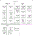
FIG. 2 is a block diagram of one embodiment of a system.
FIG. 3 is a block diagram of one embodiment of a steerable positioning element.
FIG. 4A is a flow chart of one embodiment of using a steerable positioning element.
FIG. 4B is a flow chart of one embodiment of verification of the positioning of the steerable positioning element.
FIG. 4C is an illustration of one embodiment of display movement in a steerable display.
FIG. 5 is a flow chart of another embodiment using a steerable positioning element.
FIG. 6 is a flow chart of one embodiment of controlling the use of a steerable element.
Detailed Description
A steerable positioning element is disclosed that may be used to implement a steerable display. In one embodiment, the steerable positioning element may be a mirror, lens, prism, dichroic mirror, switchable crystal or other positioning element. In one embodiment, the steerable display is designed to be positionable to provide a high resolution display in the area of the user's fovea. The "fovea" is a small depression in the retina of the eye where vision is highest. In another embodiment, the steerable display may be positioned to provide a heads-up display or sprite in a particular location. The location may be based on the user's surroundings, the user's gaze, other external data, or other factors. In one embodiment, the steerable display may be used in a virtual reality and/or augmented reality display. The steerable display may also be used for any other purpose where a high resolution display is designed to be positioned.
The following detailed description of embodiments of the invention refers to the accompanying drawings, in which like references indicate similar elements, and in which is shown by way of illustration specific embodiments in which the invention may be practiced. These embodiments are described in sufficient detail to enable those skilled in the art to practice the invention. Those skilled in the art will appreciate that other embodiments may be utilized and that logical, mechanical, electrical, functional and other changes may be made without departing from the scope of the present invention. The following detailed description is, therefore, not to be taken in a limiting sense, and the scope of the present invention is defined only by the appended claims.
FIG. 1A illustrates one embodiment of a steerable positioning element. In one embodiment, system 110 includes a display element 120 supported by a gimbal 155 and a support structure column 125.
The display element 120 is pivotable along two axes. In one embodiment, the system includes two gimbals 155, each providing pivoting along one axis. The pivoting of the display element 120 is controlled by a piezoelectric element 135 mounted to a flexible arm 130, which acts as an X-axis controller and a Y-axis controller. In one embodiment, flexible arm 130 is made of metal. In one embodiment, the flexible arm supports a piezoelectric element 135. The flexible arms 130 provide a static force to the sides of the assembly to ensure that when the piezoelectric element 135 is actuated, the piezoelectric element 135 exerts a force perpendicular to the drive surface of the display element 120 and remains in contact with the display element 120 when the piezoelectric element is at rest.
In one embodiment, the range of motion of display element 120 may be +/-10 degrees along the X and Y axes. The actuator 145 drives the piezoelectric element 135 to control the movement.
In one embodiment, the microcontroller 147 receives control data from the system and controls the driver 145 to drive the piezoelectric element 135 to move the display element 120.
In one embodiment, the position sensor 140 is used to verify the actual position of the display element 120. In one embodiment, the position sensor 140 may be one or more magnetic sensors capable of sensing relative changes in the magnetic field of one or more magnets associated with the display device. In one embodiment, the magnet is located near the outer diameter of the display element 120. In one embodiment, the two magnets are positioned 90 degrees apart radially. In one embodiment, the magnet and associated magnetic sensor are positioned opposite the drive surface. This achieves the least cross-coupling and the most accurate measurement.
In one embodiment, the weight of the drive element is balanced by the weight of the magnets on the display element 120. In one embodiment, the magnet may be a rare earth magnet. The magnetic sensor is placed close to the magnet. In another embodiment, four magnets may be used. In one embodiment, in a four magnet configuration, two magnets are positioned opposite the drive element and two additional magnets are positioned further away from the display element. This adds more mass to the system, but provides the ability to cancel out other magnetic fields in space (including the earth's magnetic field) to more accurately measure changes in the magnetic field based on movement of the display element 120. In one embodiment, the magnetic sensor is a hall effect sensor. In one embodiment, the magnetic sensor is a magnetometer.
In one embodiment, one or more additional magnetic sensors are used to measure the earth's magnetic field or other ambient magnetic field. In one embodiment, the effects of the ambient magnetic field are subtracted to cancel out their effect on the display element position measurement. In one embodiment, the additional sensor is oriented to be substantially aligned with the measurement sensor on the component. In one embodiment, a single 3-axis magnetic sensor may be used. In one embodiment, a differential sensor may be used.
In one embodiment, the calculation comparing the actual position with the indicated position occurs on a processor, as will be described with reference to fig. 2. In another embodiment, analog control circuitry that does not utilize the microcontroller 147 may be used to control the positioning elements.
The display element 120 may be a mirror, a lens, a prism, a Holographic Optical Element (HOE), a liquid crystal polymer, and/or another element for directing light for a steerable display. In one embodiment, the display element 120 may be a fresnel reflector, a diffractive element, a surface relief grating, a light guide, a waveguide, or a volume hologram.
In one embodiment, the piezoelectric element 135 is an actuator that moves the display element 120. Alternatively, the piezoelectric element 135 may be replaced with a magnetic and/or inductive element, a nanomotor, an electrostatic element, or other device capable of moving the display element 120 with the precision and speed required by the display system.
FIG. 1B is a top view of the steerable positioning element of FIG. 1A.
FIG. 1C is another embodiment of a steerable positioning element, with the addition of a flexible printed circuit board 152, and moving the microcontroller to a separate board. In one embodiment, the flexible printed circuit board 152 is woven therein as shown. This makes the steerable positioning element somewhat lighter.
The following table illustrates an exemplary configuration of the optical and physical properties of one embodiment of the steerable positioning element. Note that while these tables show measured values, and in some cases, ranges of preferred embodiments, variations of these ranges, and particularly additional precision, may be preferred when possible. Further, in one embodiment, while ranges are provided, the system is not limited to these ranges.
In one embodiment, the system may include two mirrors.
In one embodiment, the fast moving element may be designed to match the eye's movement in speed, with a small angle movement range of 0.3 ° within 300 μ s and a large angle movement range of 2 ° -20 ° within 300 μ s. Such fast moving elements can move each frame and ignore saccades, which are not noticeable to the user because the speed of movement is fast enough.
In one embodiment, a medium fast movement display element may also move each frame, with a small angle movement range of 0.3 in 4ms and a large angle movement range of 2-20 in 8-50 ms. In one embodiment, this configuration allows saccades to stabilize at the onset of eye stabilization time.
In one embodiment, the small angle movement range of the medium and slow speed mirror is 0.6 degrees in 9ms, and the large angle movement range is 2-20 degrees in 8-50 ms. In one embodiment, the slow-medium mirror moves at approximately the same speed as the fast-medium mirror over a larger angle, but moves slower over a smaller angle. However, in one embodiment, even the slow-medium mirror can move each frame.
The slow mirror has a small angular movement range of 0.15 deg. within 16 milliseconds (ms) and a large angular movement range of 2 deg. -20 deg. within 20 ms-100 ms. In one embodiment, the slow mirror utilizes blank frames during movement due to its slower speed. In one embodiment, the blanking frame may be a subframe of a display capable of subframe blanking. In one embodiment, the slow mirror utilizes saccadic masking (saccadic masking) and relies on eye stabilization time (setting time) to ensure that the user does not feel the movement of the display controlled by the mirror.
In one embodiment, the system is designed to move the mirror during the time that the display is off. For most OLED-based VR displays, the duty cycle is in the range of 20% (i.e., the display itself is only on for 20% of the frame time). The steerable display may be moved during periods when the display is off. The specific angles, speeds and configuration details discussed are, of course, merely exemplary. Faster, slower or intermediate mirrors with different specifications may be used.
The following table should be considered as an exemplary configuration. Those skilled in the art will appreciate that these aspects may be varied without departing from the scope of the invention.
FIG. 1D shows another embodiment of a steerable positioning element 111. In one embodiment, system 111 includes a display element 174 supported by flexible arm 170 and support structure base 160.
The display element 174 is pivotable along two axes. The pivoting of the display element 174 is controlled by the piezoelectric element 172. In one embodiment, the range of motion may be +/-18 degrees along the X and Y axes. The actuator 164 drives the piezoelectric element 172 to control the movement.
The microcontroller 176 receives control data from the system and controls the driver to move the display element 174. The position sensor 168 is used to verify the actual position of the display element 174. In one embodiment, the calculation of comparing the actual position to the indicated position occurs on a processor, as described below.
In one embodiment, the piezoelectric element 172 is an actuator that moves the display element 174. Alternatively, the piezoelectric elements 172 may be replaced with magnetic and/or inductive elements, nanomotors, electrostatic elements, or other devices capable of moving the display elements 174 with the precision and speed required by the display system.
FIGS. 1E and 1F are perspective and cross-sectional views of another embodiment of a steerable positioning element. The display element 180 is supported in place by a plurality of positioning posts 184. Positioning post 185 enables movement of display element 180. Positioning posts 185 are supported by base structure 182. Although not shown, this embodiment also includes a microcontroller and a position sensor.
The cross-section in FIG. 1F shows the components of locating post 185 and central support 188 of the embodiment of FIG. 1E. In one embodiment, the system includes two or more locating posts 192 and a central support 188. In one embodiment, center support 188 is located at the center of display element 180 and provides a stable point about which the display element tilts. In one embodiment, each positioning post 192 includes an actuator 198, a moving support structure 196, and an angled top 194.
In one embodiment, the actuator 198 is a piezoelectric element that moves the moving support structure 196 up and down. Alternatively, the actuator 198 may be a magnetic and/or inductive element, a nanomotor, an electrostatic element, or other actuator mechanism that enables the moving support structure 196 to move with the precision and speed required by the display system.
The mobile support structure 196 moves up and down and is connected with a sloped top 194. In one embodiment, the sloped top 194 is rounded or has a rounded top that fits into the recess 190 in the display element 180. In one embodiment, the connection between the mobile support structure 196 and the inclined top 194 is magnetic.
The tilt top 194 enables the display element 180 to tilt by moving up and down. Because the sloped top 194 is smooth and fits into the notch 190, the sloped top remains in contact with the display element 180.
In one embodiment, the sloped top 194 is a freely rotating sphere that is magnetically coupled to the mobile support structure 196 and the notch 190. In this way, the system may utilize an actuator with rapid up and down motion capability to provide a range of motion to the display element 180. The range of motion and the ability of the display element is discussed below with reference to tables 5 through 6.
Tables 1 and 2 show exemplary optical, physical and other characteristics of the first configuration of the steerable mirror.
Table 1:

table 2:
| other characteristics | One embodiment | Note |
| Occupied area | 8mm×8mm | Maximum 12mm x 12mm |
| Height | 2mm | Maximum 5mm |
| Scan or aim and shoot? | Aiming and shooting at once | |
| Mechanical clamping | Edge groove in package | Spare screw |
| Influence of gravity | Is free of | |
| Magnetic shield | Does not need to use | |
| Optical system | One embodiment | Note |
| Mirror coating | Protected silver or reinforced aluminum | |
| Optical power | LED illumination, mW range | May include laser illumination |
| Control interface | SPI、I2S、I2C、PWM | |
| Power consumption | <50mW(DC) | <10mW(DC) |
| Operating temperature | -20 ℃ to 65 DEG C | At least 0 ℃ to 40 DEG C |
| Storage temperature | -40 ℃ to 85 DEG C | |
| Impact and vibration requirements | Impact according to DIN EN 60068-2-27 | |
| Cycle life | 220M full cycle | At least 95M full period |
| Life span | 7 years old | For 3 years |
| Conform to | RoHS |
Tables 3 and 4 illustrate exemplary optical, physical and other characteristics of the second configuration associated with the steerable positioning element of FIG. 1A.
Table 3:

table 3: continuously for

Table 4:

tables 5 and 6 illustrate exemplary optical, physical and other characteristics of the third configuration associated with the steerable positioning elements of FIGS. 1E and 1F.
Table 5:

table 5: continuously for


Table 6:

note that the above tables describe embodiments of mechanical, optical, and physical properties, which describe a set of embodiments using various configurations of steerable display elements that use mirrors as positioning elements. Those skilled in the art will appreciate that the above ranges for the different positioning elements may be modified.
FIG. 2 illustrates one embodiment of an exemplary optical system 210, 280 and associated processing system 238. In one embodiment, the processing system may be implemented in a computer system that includes a processor. In one embodiment, the processing system 238 may be part of a display system. In another embodiment, the processing system 238 may be remote. In one embodiment, the optical system 210, 280 may be implemented in a wearable system, such as a head-mounted display. The steerable display image is presented to the eyes of the user through the right-eye steerable display 220 and the left-eye steerable display 230 that guide the steerable displays. In one embodiment, the steerable displays 220, 230 direct the steerable display images primarily toward the center of the field of view of the user's eyes. In another embodiment, the images may be directed to different locations, as described below. In one embodiment, the manipulatable display image is a high resolution image. In one embodiment, the manipulatable display image is a variable resolution image. In one embodiment, the variable resolution corresponds to a change in the maximum resolution perceived by the user's eye, which decreases as the user's eye moves farther away from the center.
An image for the right eye is created using the first display element 222. In one embodiment, the display element is a Digital Micromirror Device (DMD). In one embodiment, display element 222 is a scanning micro-mirror device. In one embodiment, the display element 222 is a scanning fiber optic device. In one embodiment, the display element is an Organic Light Emitting Diode (OLED). In one embodiment, the display element 222 is a Liquid Crystal On Silicon (LCOS) panel. In one embodiment, the display element 222 is a Liquid Crystal Display (LCD) panel. In one embodiment, display elements 222 are micro LEDs or micro light emitting diode (μ LED) panels. In one embodiment, the display element is a scanning laser system. In one embodiment, the system is a hybrid system having an off-axis Holographic Optical Element (HOE). In one embodiment, a system includes a waveguide. In one embodiment, the waveguide is a multilayer waveguide. In one embodiment, a display element may comprise a combination of such elements. Fig. 3 below discusses the display element in more detail.
In one embodiment, the first display element 222 is located in a near-eye device such as glasses or goggles.
The intermediate optical element 224 is used to set the focus and field of view of the steerable display. The intermediate optical element 224 may include, but is not limited to, lenses, mirrors, and diffractive optical elements. In one embodiment, the focal point of the virtual image is set to infinity. In another embodiment, the focal point of the virtual image is set closer than infinity. In one embodiment, the focus of the virtual image may be changed. In one embodiment, the virtual image may have two or more focal lengths perceived simultaneously.
In one embodiment, the steerable display image is directed primarily toward the center of the field of view of the user's eyes. In one embodiment, the field of view (FOV) of the steerable display image is greater than 1 degree. In one embodiment, the FOV of the steerable display image is between 1 degree and 20 degrees. In one embodiment, the steerable display image may be greater than 5 degrees to account for inaccuracies in eye tracking, provide the area required for successful blending so that the user is not aware of the blending, and account for the time it takes to reposition the steerable display for various types of eye movements.
In one embodiment, the system further includes a low resolution field display image having a field of view of 20-220 degrees.
In one embodiment, the steerable display image is projected directly onto the user's eyes using a set of one or more positioning elements 226 that are fully or partially transparent. In one embodiment, the positioning element 226 comprises a steerable mirror, such as the steerable positioning element shown in FIG. 1A. In one embodiment, the positioning element 226 comprises a curved mirror. In one embodiment, the positioning element 226 comprises a Fresnel reflector. In one embodiment, the positioning element 226 comprises a diffractive element. In one embodiment, the diffractive element is a surface relief grating. In one embodiment, the diffractive element is a volume hologram. In one embodiment, display 220 may include focus adjuster 223, which enables the display to display image elements in multiple focal lengths in the same frame. In one embodiment, focus adjuster 223 may be an optical path length expander, as described in U.S. patent application No. 15/236,101 filed on 12.8.2016.
A similar set of elements exists for the left eye manipulable display 230. In one embodiment, the right eye steerable display 220 and the left eye steerable display 230 are matched. In another embodiment, they may comprise different elements.
In one embodiment, eye tracker 240 tracks the user's gaze vector, e.g., where the eye is looking. In one embodiment, the eye tracking system is a camera-based eye tracking system 240. In one embodiment, camera-based eye tracking system 240 includes a holographic optical element. In one embodiment, eye tracking system 240 is an infrared scanning laser with a receiving sensor. In one embodiment, infrared scanning laser eye tracking system 240 includes a holographic optical element. In one embodiment, eye tracking system 240 is an optical flow sensor. Other eye tracking mechanisms may be used. The position calculator 245 determines the center of the user's field of view based on data from the eye tracking system 240.
In one embodiment, the adjustable positioning elements 226, 236 are used to adjust the right eye steerable display 220 and the left eye steerable display 230 to position the image to be directed primarily toward the center of the field of view of the user's eyes. In one embodiment, the adjustable position elements 226, 236 are used to adjust the right eye steerable display 220 and the left eye steerable display 230 to position the eye range (eye box) or exit pupil towards the center of the field of view of the user's eyes. In one embodiment, the orientation of the image is adjusted by changing the angle of one of the mirrors, the position elements 226, 236. In one embodiment, the angle of the mirror is changed by using electromagnetic force. In one embodiment, the angle of the mirror is changed by using electrostatic forces. In one embodiment, the angle of the mirror is changed by using piezoelectric forces, as shown in FIG. 1A. In one embodiment, the adjustable element is an image source or display element 222, 232 that moves to position an image. In one embodiment, the image is positioned to be directed to the center of the field of view of the user's eyes. In another embodiment, another position element 226, 236, such as a steering element 226, 236, may be changed.
The field display 280 communicates with the processing system 238 via communication logic 270, 290. In one embodiment, there may be multiple displays. Here, two field displays are shown, a field display 285 and a peripheral display 288. Additional resolution levels are also shown. In one embodiment, the field displays 280 may include a single field display 285 for viewing by both eyes of the user, or one field display per eye. In one embodiment, the field display 280 may have a variable resolution. In one embodiment, the resolution drops towards the outside of the display 280, corresponding to a drop in the maximum resolution perceived by the eye.
In one embodiment, the synchronization signal generator 292 is used to synchronize the display of the independently steerable display 210 with the display of the field display 280 when the field display 280 is a separate system. In one embodiment, a synchronization signal generator 292 is used to synchronize a tuneable mirror or other positioning element of a steerable display with a field display. This results in synchronization of the displays. In one embodiment, the field display 280 includes a blender system 294 for blending the edges of the steerable display image with the field display image to ensure that the transition is smooth.
In one embodiment, a lower resolution field display image is presented to the user using a fully or partially transparent optical system. In one embodiment, the partially transparent system comprises a waveguide optical system. In one embodiment, the partially transparent system includes a partial mirror that may be flat or have optical power. In one embodiment, the partially transparent system comprises a diffractive optical element. In one embodiment, the image is presented to the user through a direct-view optical system. In one embodiment, the partially transparent system includes inclusions that reflect or scatter light.
In one embodiment of the field display 280, an additional display subsystem is used to display images in the area of the monoscopic peripheral display 288. In one embodiment, the subsystem is an LED (light emitting diode) array. In one embodiment, the subsystem is an OLED (organic LED) array. In one embodiment, the display subsystem uses a scanning laser. In one embodiment, the subsystem uses an LCD (liquid crystal display) panel. In one embodiment, the field display 280 is an LCOS (liquid Crystal on silicon) display. In one embodiment, the field display is a DLP (digital light processing) display. In one embodiment, the subsystem has no intermediate optical elements to manipulate the FOV or focus of the image. In one embodiment, the subsystem has an intermediate optical element. In one embodiment, the intermediate optical elements comprise a microlens array.
Image data displayed by the steerable display 210 and the field display 280 is generated by the processing system 238. In one embodiment, the system includes an eye tracker 240. In one embodiment, eye tracker 240 tracks the user's gaze vector, e.g., where the eye is looking. In one embodiment, the eye tracking system is a camera-based eye tracking system 240. Alternatively, the eye tracking system 240 may be infrared laser based. The foveal position calculator 245 determines the center of the user's field of view based on data from the eye tracking system 240. In one embodiment, the foveal position calculator 245 additionally uses data from the slip detection system. In one embodiment, the slippage detection system detects movement of the headset/goggles on the user's head and detects slippage or other displacement of the true position of the user's eyes relative to the calculated position. In one embodiment, the foveal position calculator 245 may compensate for this slippage by adjusting the calculated foveal position that is used by the system to position the steerable display.
In one embodiment, the processing system 238 also includes a foveal location verifier 247 that verifies the location of the positional elements 226, 236 to ensure that the displays 220, 230 are properly positioned. In one embodiment, this includes re-evaluating the position of the steerable display relative to the center of the field of view of the user's eyes in accordance with the movement of the steerable display. In one embodiment, the foveal position verifier 247 uses a sensing mechanism to provide feedback to verify that the positional element has reached its target position. In one embodiment, the sensing mechanism may be a camera. In one embodiment, the sensing mechanism may be an actuator. The sensing mechanism in the location validator 247 may be a magnetic sensor. The sensing mechanism may be another type of sensor capable of determining the position of the optical element. In one embodiment, the foveal position verifier 247 may alter the display to provide the correct image data if the actual position of the manipulatable display is not the target position. This is described in more detail below.
In one embodiment, the eye movement classifier 260 may be used to predict where the user's gaze vector will move. The predicted localizer 265 may use this data to move the manipulatable display 220, 230 based on the next position of the user's gaze vector. In one embodiment, the intelligent positioner 267 can utilize user data such as eye movement classification and eye tracking to predictively position the display 220, 230. In one embodiment, the intelligent locator 267 can additionally use data regarding upcoming data in the frame to be displayed to identify the optimal location of the display 220, 230. In one embodiment, the intelligent positioner 267 can position the display 220, 230 at a location not indicated by the gaze vector. For example, if the displayed frame data has only a small amount of relevant data (e.g., a butterfly illuminated on an otherwise dark screen), or the frame is intended to be viewed by a viewer at a particular location.
The processing system 238 may also include cut-out logic 250. The cut-out logic 250 defines the position of the manipulatable display 220, 230 and provides the display information with the cut-outs to the associated field display 280. The field display 280 renders the data to generate a lower resolution field display image that includes a cutout of a corresponding portion of the image in the field display. This ensures that there is no interference between the manipulatable display image and the field image. In one embodiment, when there is a cut, the blender logic 255 blends the cut edge with the manipulatable image to ensure that the transition is smooth. In another embodiment, the steerable display may be used to display a sprite, i.e. a brighter element overlaid on a lower resolution field image. In this case, neither the cut-out logic 250 nor the mixer logic 255 is necessary. In one embodiment, cut-out logic 250 and mixer logic 255 may be selectively activated as desired.
In one embodiment, the system may synchronize the steerable display 210 with a separate field display 280. In this case, in one embodiment, the synchronization logic 272 synchronizes the displays. In one embodiment, the independent field display 280 is synchronized with an adjustable mirror or other positioning element of the steerable display 210. This results in synchronization of the displays. The field display 280 may receive positioning data. In one embodiment, there may be no cut-out in this case.
In one embodiment, the processing system 238 may include an optical distortion system 275 for the steerable display 210, with distortion increasing from the center to the edges of the image. This intentional distortion will result in an increase in the perceived size of pixels moving from the center of the image to the edge. This change in perceived resolution will reduce the amount of processing required since fewer pixels are required to cover the same angular area of the manipulatable display image. The optical distortion may contribute to the mixing between the steerable display 210 and the field display 280. In another embodiment, the steerable display 210 including the optical distortion system 275 may be used without a field display. It also provides easier optical design and saves processing for mixing.
In one embodiment, the variable resolution high distortion image has a large ratio between the center and the edge. The total FOV of the display will be large (up to 180 degrees).
In one embodiment, roll-off logic 277 provides roll-off at the edge of the display. In one embodiment, the roll-off may include a resolution roll-off (decreasing resolution towards the edge of the display area). In one embodiment, this may be accomplished by amplification by optical distortion system 275. The roll-off in one embodiment comprises a brightness and/or contrast roll-off (reducing brightness and/or contrast towards the edge). This roll-off is designed to reduce the steepness of the display edge. In one embodiment, the roll-off may be designed to roll off to "none," i.e., gradually decrease from full brightness/contrast to gray or black or ambient color. In one embodiment, the steerable display 210 may use roll-off logic 277 when there is no associated field display. In one embodiment, when there is a field display in the system, the roll-off logic 297 may be part of the field display 280.
Fig. 3 illustrates one embodiment of a positional element 300. In one embodiment, the positional elements comprise separate positional elements for the right and left eyes of the user. In one embodiment, instead of using one steerable element 310 for each eye, the system may use two or more steerable elements 310 for each eye. In one embodiment, the two-element system may include separate steerable elements 310 for X-axis movement and Y-axis movement for each eye. In one embodiment, two or more steerable elements 310 may be used, each steerable element 310 having one or more steerable axes.
The steerable element 310 may comprise one or more of a mirror, prism, fresnel lens or other element positioned such that light may be directed to a particular location. In one embodiment, the steerable element 310 is a curved mirror.
The X-axis attachment 320 provides a physical moving element for rotation about the X-axis, while the Y-axis attachment 350 provides a moving element for pivoting about the Y-axis. In one embodiment, the moving elements are a pivot 150 and a gimbal 155.
The X-axis controller 330 and the Y-axis controller 360 control the movement, while the X-axis actuator 340 and the Y-axis actuator 370 provide the physical movement. The piezoelectric element in one embodiment is a controller. The movement data comes from the microprocessor 390. In one embodiment, the microprocessor 390 is part of the main control circuitry for the steerable display.
In one embodiment, the system further comprises a position verifier 380 that verifies the actual position of the steerable element 310 along the X and Y axes. In one embodiment, validator 380 comprises a magnetic sensor that senses movement of a magnet associated with the movable element. In another embodiment, the verifier 380 may be coupled to the actuators 340, 370 or the accessories 320, 350 and determine the position of the steerable element 310 based on the physical position of the element supporting the steerable element 310. Other methods of determining the actual position of the steerable element 310 may be used.
In one embodiment, validator 380 provides data to microprocessor 390. The microprocessor may compare data from the controllers 330, 360 with data from the location validator 380. This may be used for recalibration as well as to identify positioning problems of the steerable element 310. In one embodiment, to enable the position verifier 380, the bottom of the steerable element 310 has markings that are used by the position verifier 380 to determine the actual position of the steerable element 310.
FIG. 4C illustrates one embodiment of the movement of the display over time. In one embodiment, as the user's eyes move, the movement may correspond to the user's foveal position. At any time there is a small area to which the image is displayed. The position of the high resolution 5 degree display (in one embodiment) is focused at the center of the user's field of view. In one embodiment, the low resolution field image provides a large field of view. But because the relative resolution of the eye outside the foveal region is low, the user perceives the combined image, including a small high resolution steerable image and a larger low resolution field image, as high resolution over a large field of view.
FIG. 4A is a flow chart of one embodiment of utilizing a steerable display. The process begins at block 410. In one embodiment, the display system is matched to the user before the process begins. This initial setup includes determining the interpupillary distance (IPD) and any prescription required to ensure that the user's "baseline" display is accurate.
At block 415, the user's eyes are tracked. In one embodiment, an IR camera is used to track the eye. In one embodiment, eye tracking identifies a gaze vector of the user, such as where the user is focusing.
At block 420, the system calculates a gaze vector of the user. Eye tracking may identify left and right eye gaze vectors/angles and gaze centers (derived from the L/R eye gaze vectors). In one embodiment, eye tracking may determine the position (X, Y, Z) and orientation (roll, pitch, yaw) of the left and right eyes relative to a baseline reference frame. In one embodiment, the baseline reference frame is determined when the display is initially matched to the user and the user's interpupillary distance, diopter, and other relevant data are determined.
At block 420, a location of the fovea is determined based on the gaze vector data. In one embodiment, the foveal position includes the coordinates (X, Y, Z) and orientation (roll, pitch, yaw) of each eye.
At block 425, the process determines whether the steerable display should be repositioned. This is based on comparing the current position of the manipulable display with the gaze vector of the user or the expected position of the image. If they are misaligned, the system determines that the steerable display should be repositioned. If so, at block 430, the display is repositioned. The repositioning of the display is designed such that the movement of the steerable display is not perceived by the user. In one embodiment, this may be accomplished by: the movement is accomplished in a manner imperceptible to the user by using a sufficiently fast mirror. In one embodiment, this may be accomplished by timing the movement as a user's blinking eye or eye movement. In one embodiment, if the intended display is moved beyond a certain distance, the display is blank during the movement. This ensures that the user is not aware of the movement. In one embodiment, the specific distance is greater than 0.5 degrees. In one embodiment, if the movement occurs while the user blinks, it is expected that the display will not be blank. Note that although the term "repositioning" is used, this corresponds to movement of the positioning element to adjust the position of the display.
The process then continues to block 435 whether or not the display is repositioned.
At block 435, optionally, the system cuts out the portion of the field display image that is to be located in the same position as the manipulatable display image. This prevents the field display from interfering with the steerable display. In one embodiment, the cut-out is performed at the rendering engine. In another embodiment, the image may be a sprite or other bright image element that does not need to be cut out for clarity. In this case, the block may be skipped. In one embodiment, if the user eye tracking indicates that the user's gaze has moved far from the baseline reference, then the cut-out is skipped. The baseline reference is the user's default gaze location from which to track the movement of the gaze. Substantial movement from the baseline reference means that the system cannot determine the user's correct gaze location. In this case, in one embodiment, the steerable display image may be discarded, or the steerable display may be temporarily turned off. In one embodiment, this may be accomplished by making the steerable display black out so that it is not visible to the user. In various embodiments, this may be accomplished by disabling the backlight, disabling the laser or LED illumination source, blanking the pixels, or by another method.
At block 440, in one embodiment, edges between the steerable display image and the field images are blended. This ensures a smooth and imperceptible transition between the field image and the manipulatable display image. At block 445, the blended image is displayed to the user, thereby merging the steerable display and the field display. The process then returns to block 410 to continue tracking and display. Note that while this description discusses a steerable display image and a field image, the images considered include sequential images of video. It is also noted that although the present description in some embodiments utilizes a combination of a steerable display and a field display, the steerable display can be used without the presence of a field display. In these cases, the process may include only blocks 415 through 430.
FIG. 4B illustrates one embodiment of a corrective action that may be taken when the display position verification indicates that the actual position of the manipulatable display does not match the expected position. The process begins at block 450.
At block 452, steerable display positioning is initiated. In one embodiment, this corresponds to block 430 of FIG. 4A. Returning to FIG. 4B, at block 454, the actual position of the manipulatable display is verified. In one embodiment, one or more sensors are used to determine the position and orientation of the steerable display. In one embodiment, the sensor may include a camera, a mechanical element that detects the position of a tuneable mirror or other positioning element, or the like. In one embodiment, this is accomplished by the location verifier 380 of FIG. 3.
At block 456, the process determines whether the manipulatable display is properly positioned. The steerable display is positioned correctly in the calculated position to display the image in the appropriate position for the user. If the steerable display is properly positioned, at block 464, an image is displayed. In one embodiment, this includes displaying a blended image that includes the manipulatable display image and the associated field display image at the calculated position, as discussed above with respect to FIG. 4A. The process then ends at block 475.
If at block 456 the process determines that the manipulatable display is not properly positioned, the process continues to block 458.
At block 458, the process determines whether there is sufficient time to reposition the manipulatable display. The determination is based on the distance that needs to be moved, the speed of movement, and the time until the processing system sends the next image.
In one embodiment, it also depends on the user's eye movement. In one embodiment, when no image is perceived, the system preferably moves the manipulable display when the user blinks. In one embodiment, the repositioning occurs during a black screen period of the display. For example, moving only one degree along one coordinate takes less time than moving the steerable display significantly in three dimensions. If there is sufficient time, the process returns to block 452 to reposition the manipulatable display. Otherwise, the process continues to block 460.
At block 460, the process determines whether the actual position of the manipulatable display is within the range of expected positions. In one embodiment, "in range" in the context means that the system is able to adjust the display for the discrepancy. If so, the process continues to block 462.
At block 462, the data processed for display on the steerable image is adjusted for presentation at the actual location. The adjusted image is then displayed at block 464. For example, in one embodiment, if the difference in position is very small, the originally computed image may be rendered in the wrong position without causing visual artifacts. In another embodiment, the image may be adjusted to be properly rendered at the actual location. For example, the image may be cropped, brightened, warped, contrast adjusted, chromaticity coordinates (white point) adjusted, cropped, and laterally moved to account for positional differences.
In one embodiment, the radial position of the edge blending may be moved or changed for blending display. In one embodiment, the system may over-render (over-render), e.g., render 5.5 degree visual images for a 5 degree steerable display, allowing 0.5 degree offset without re-rendering.
If the steerable display is not in range, then at block 466, in one embodiment, the frame data is sent to the field display for presentation. At block 468, in one embodiment, the steerable display image is not displayed. In one embodiment, the frame is dropped. In another embodiment, the steerable display is temporarily blank. In one embodiment, the steerable display is not considered to be in range if the user eye tracking indicates that the user's gaze has moved too far out of the baseline reference.
At block 470, in one embodiment, the field display image is rendered without image cropping and without display or rendering of the manipulatable display image. At block 472, a field display image is displayed. The process then ends.
FIG. 5 is a flow diagram of one embodiment utilizing a steerable display in which positioning is independent of the user's gaze vector. This may be applicable, for example, when the display is the only bright element on a head-up display, or sprite, or other dark display. Other reasons for providing positioning that is not based on the user's gaze vector may be found. In one embodiment, this configuration may be combined with the configuration of fig. 4A described above, where the positioning is based on the gaze vector. That is, the same system may vary between being based on a gaze vector and not being based on a gaze vector.
The process begins at block 510. In one embodiment, the display system is matched to the user before the process begins.
At block 515, the position of the steerable display is determined. This determination may be made based on external data (e.g., in a virtual reality display) or other determination. In one embodiment, the decision may be made based on processor data.
At block 520, the process determines the current position of the manipulatable display.
At block 525, the process determines whether the steerable display should be repositioned. This is based on comparing the current position of the steerable display with the expected position of the image. If they are misaligned, the system determines that the steerable display should be repositioned. If so, at block 530, a display relocation is triggered. In one embodiment, the repositioning of the display is designed such that the movement of the steerable display is not perceived by the user. In one embodiment, as described above, this may be accomplished by: the movement is accomplished in a manner imperceptible to the user by using a sufficiently fast mirror. In one embodiment, this may be accomplished by timing the movement as a user's blinking eye or eye movement. In one embodiment, if the intended display is moved beyond a certain distance, the display is blank during the movement. This ensures that the user is not aware of the movement. In one embodiment, the specific distance is greater than 0.5 degrees. In one embodiment, if the movement occurs while the user blinks, it is expected that the display will not be blank. Note that although the term "repositioning" is used, this corresponds to movement of the positioning element to adjust the position of the display.
The process then continues to block 535, whether or not the display is repositioned.
At block 535, optionally, the system cuts out the portion of the field display image that will be positioned in the same location as the manipulatable display image. This prevents the field display from interfering with the steerable display.
In one embodiment, the cut-out is performed at the rendering engine. In another embodiment, the image may be a sprite or other bright image element that does not need to be cut out for clarity. In this case, the block may be skipped.
At block 540, in one embodiment, the system determines whether the edge between the steerable display image and the live image should be blended. This ensures a smooth and imperceptible transition between the field image and the manipulatable display image. This may not be relevant when there is no field display, or when the steerable display is a sprite or other overlay element. If the system determines that edges should be blended, then at block 545, the edges are blended.
At block 550, the images from the steerable display are displayed to the user, optionally incorporating data from the field display. The process then returns to block 510 to continue tracking and display. Note that while this description discusses a steerable display image and a field image, the images considered include sequential images of video. It is also noted that although the present description in some embodiments utilizes a combination of a steerable display and a field display, the steerable display can be used without the presence of a field display.
FIG. 6 is a flow chart of one embodiment of controlling the use of a steerable element. In one embodiment, the system determines the type of eye movement: saccades or smooth pursuits. For smooth tracking, in one embodiment, the system moves one frame at a time and matches eye movement so that the steerable display can be turned on during the movement. In one embodiment, this may be done when moving up to 3 degrees per frame. For faster eye movement, in one embodiment, the steerable display may be black-screened. For saccadic eye movements, in one embodiment, the system causes the steerable display to temporarily blank the screen while moving to avoid visual aberrations. The system is designed to have a faster settling time than the user's eye. Thus, the display is designed to activate again when the eye has stabilized after a saccadic movement and return to full resolution. FIG. 6 illustrates one embodiment of moving the steerable display for saccades or other rapid movements.
The process begins at block 605. In one embodiment, the process runs as long as the manipulatable display is active. At block 610, a user gaze location is monitored for the manipulatable display. In one embodiment, the steerable display is directed toward the user's fovea.
At block 615, a new gaze location is determined. In one embodiment, the gaze location is identified using a camera aimed at the user's eyes.
At block 620, the degree of movement required for the manipulable display to match the new gaze vector is identified.
At block 625, a time to move the manipulatable display to a new position is determined. In one embodiment, a look-up table is used. In one embodiment, the determined "gaze vector" may be a plurality of gaze vectors over a time, such as in smoothly tracking eye movements.
At block 630, the display may be manipulated to be black and begin moving. In one embodiment, the movement is initiated only after the steerable display is blank. In one embodiment, the steerable display may be blacked out by turning off the light source. In another embodiment, the steerable display may be turned off by having the mirror black screen. In another embodiment, the steerable display may blank the screen by disabling the backlight or illumination. In another embodiment, the steerable display may blank the screen by setting the pixels to black.
At block 635, the steerable display is moved. During this time, since the steerable display is blank, in one embodiment, the field display is filled to cover the entire display area. In another embodiment, there may be no field display, in which case this is not applicable.
In one embodiment, at block 640, the process determines whether the time to complete the calculated movement has elapsed. If not, the process continues moving at block 635.
In one embodiment, if time has elapsed, the system provides a signal to activate the manipulatable display at block 645. In another embodiment, the signal timing may be based on movement data from the microprocessor and the position verifier.
When a signal is received to activate the display at block 645, the process verifies that the display has stopped moving and has stabilized at block 650. By "stable" is meant that the display is stable and does not vibrate due to movement. In one embodiment, this is a closed loop determination made by a microprocessor in the display.
If the display has stabilized, the manipulatable display is activated at block 655. In one embodiment, if a field display is present, it may be cut out for the area in which the steerable display image is shown. The process then continues to block 610 to continue monitoring the gaze location of the user and determining a new gaze location. In this way, the steerable display is moved to match the user's gaze while not providing a visual indication of the movement.
In the foregoing specification, the invention has been described with reference to specific exemplary embodiments thereof. It will, however, be evident that various modifications and changes may be made thereto without departing from the broader spirit and scope of the invention as set forth in the appended claims. The specification and drawings are, accordingly, to be regarded in an illustrative rather than a restrictive sense.
Claims (19)
1. A steerable display system, comprising:
a display element;
a positional element for positioning an image generated by the display element, the positional element comprising:
a steerable element;
an X-axis controller for pivoting the steerable element about an X-axis;
a Y-axis controller for pivoting the steerable element about a Y-axis;
wherein movement of the steerable element is such that no movement is perceived by the user;
the steerable element is caused to have a range of motion that enables a steerable display to be positioned and repositioned at a plurality of locations within the field of view of the user.
2. The steerable display system of claim 1, further comprising:
a position validator for validating an actual position of the steerable element and adjusting the steerable display image data when the actual position is not an expected position.
3. The steerable display system of claim 1, wherein the steerable element comprises one or more of: tunable mirrors, tunable prisms, acousto-optic modulators, tunable display panels, curved mirrors, diffractive elements and fresnel reflectors.
4. The steerable display system of claim 1, wherein:
the steerable display has a monocular field of view of at least 1 degree, the monocular field of view being within a scannable field of view of at least 20 degrees.
5. The steerable display system of claim 1, further comprising:
an actuator for moving the steerable element, the actuator comprising one of a piezoelectric element, a magnetic element, a nanomotor.
6. The steerable display system of claim 5, wherein the actuator has an absolute precision of +/-0.75 arc minutes and a relative precision of 0.06 arc minutes.
7. The steerable display system of claim 5, wherein the settling time is less than 2 ms.
8. A steerable display system according to claim 1, wherein the steerable element is a mirror with a diameter between 5mm and 15 mm.
9. A steerable display system according to claim 1, wherein the positional element is less than 5mm x 12 mm.
10. A steerable display system, comprising:
a movable display element;
a position element for moving the display element to position an image generated by the display element, the position element comprising:
a flexible arm supporting the movable display element;
a controller for pivoting the steerable element about an axis using the flexible arm;
wherein movement of the steerable element is such that no movement is perceived by the user;
the steerable element is caused to have a range of motion that enables a steerable display to be positioned and repositioned at a plurality of locations within the field of view of the user.
11. The steerable display system of claim 10, further comprising:
a position validator for validating an actual position of the steerable element and adjusting the steerable display image data when the actual position is not an expected position.
12. The steerable display system of claim 10, wherein the steerable element comprises one or more of: tunable mirrors, tunable prisms, acousto-optic modulators, tunable display panels, curved mirrors, diffractive elements and fresnel reflectors.
13. The steerable display system of claim 10, wherein:
the steerable display has a monocular field of view of at least 1 degree, the monocular field of view being within a scannable field of view of at least 20 degrees.
14. The steerable display system of claim 10, further comprising:
an actuator for moving the steerable element, the actuator comprising one of a piezoelectric element, a magnetic element, a nanomotor.
15. The steerable display system of claim 14, wherein the actuator has an absolute precision of +/-0.75 arc minutes and a relative precision of 0.06 arc minutes.
16. The steerable display system of claim 14, wherein the settling time is less than 2 ms.
17. The steerable display system of claim 10, wherein the steerable element is a mirror with a diameter between 5mm and 15 mm.
18. A steerable display system according to claim 10 wherein the positional elements are less than 5mm x 12 mm.
19. A steerable display system, comprising:
a display element;
two pivots about which the display element is movable in all directions;
a piezoelectric element that drives the pivot shaft to move the display element;
a magnet and associated magnetic sensor for determining the position of the display element;
wherein the position of the magnet balances the piezoelectric element such that the display element is balanced in weight.
Applications Claiming Priority (5)
| Application Number | Priority Date | Filing Date | Title |
|---|---|---|---|
| US201862777061P | 2018-12-07 | 2018-12-07 | |
| US62/777,061 | 2018-12-07 | ||
| US201962902377P | 2019-09-18 | 2019-09-18 | |
| US62/902,377 | 2019-09-18 | ||
| PCT/US2019/065101 WO2020118276A1 (en) | 2018-12-07 | 2019-12-06 | Steerable positioning element |
Publications (1)
| Publication Number | Publication Date |
|---|---|
| CN113196132A true CN113196132A (en) | 2021-07-30 |
Family
ID=70970446
Family Applications (1)
| Application Number | Title | Priority Date | Filing Date |
|---|---|---|---|
| CN201980080626.9A Pending CN113196132A (en) | 2018-12-07 | 2019-12-06 | Steerable positioning element |
Country Status (7)
| Country | Link |
|---|---|
| US (2) | US11169383B2 (en) |
| EP (1) | EP3891546A4 (en) |
| JP (1) | JP2022514217A (en) |
| KR (1) | KR20210097190A (en) |
| CN (1) | CN113196132A (en) |
| CA (1) | CA3122089A1 (en) |
| WO (1) | WO2020118276A1 (en) |
Families Citing this family (1)
| Publication number | Priority date | Publication date | Assignee | Title |
|---|---|---|---|---|
| US11181979B2 (en) * | 2019-01-08 | 2021-11-23 | Avegant Corp. | Sensor-based eye-tracking using a holographic optical element |
Citations (7)
| Publication number | Priority date | Publication date | Assignee | Title |
|---|---|---|---|---|
| US20080015553A1 (en) * | 2006-07-12 | 2008-01-17 | Jaime Zacharias | Steering laser treatment system and method of use |
| US20130114146A1 (en) * | 2011-11-04 | 2013-05-09 | Honeywell International Inc. | Steerable near-to-eye display and steerable near-to-eye display system |
| US20130208330A1 (en) * | 2012-02-14 | 2013-08-15 | Fujifilm Corporation | Mirror driving device and method of controlling the device |
| CN103261943A (en) * | 2010-12-28 | 2013-08-21 | 洛克希德马丁公司 | Head-mounted display apparatus employing one or more fresnel lenses |
| US20160363841A1 (en) * | 2015-06-09 | 2016-12-15 | Seiko Epson Corporation | Optical device and image display apparatus |
| CN108474949A (en) * | 2015-12-24 | 2018-08-31 | 星风Ip公司 | Virtual reality head-mounted display |
| US20180284451A1 (en) * | 2017-03-27 | 2018-10-04 | Avegant Corp. | Steerable High-Resolution Display |
Family Cites Families (98)
| Publication number | Priority date | Publication date | Assignee | Title |
|---|---|---|---|---|
| US4924522A (en) | 1987-08-26 | 1990-05-08 | Ncr Corporation | Method and apparatus for displaying a high resolution image on a low resolution CRT |
| US5035500A (en) | 1988-08-12 | 1991-07-30 | Rorabaugh Dale A | Automated ocular perimetry, particularly kinetic perimetry |
| US6008781A (en) | 1992-10-22 | 1999-12-28 | Board Of Regents Of The University Of Washington | Virtual retinal display |
| JPH08313843A (en) * | 1995-05-16 | 1996-11-29 | Agency Of Ind Science & Technol | Wide visual field and high resolution video presentation device in line of sight followup system |
| US8330812B2 (en) | 1995-05-30 | 2012-12-11 | Simulated Percepts, Llc | Method and apparatus for producing and storing, on a resultant non-transitory storage medium, computer generated (CG) video in correspondence with images acquired by an image acquisition device tracked in motion with respect to a 3D reference frame |
| US6204974B1 (en) | 1996-10-08 | 2001-03-20 | The Microoptical Corporation | Compact image display system for eyeglasses or other head-borne frames |
| US6097353A (en) | 1998-01-20 | 2000-08-01 | University Of Washington | Augmented retinal display with view tracking and data positioning |
| EP1194806A4 (en) | 1999-06-21 | 2008-07-23 | Microoptical Corp | Eyeglass display lens system employing off-axis optical design |
| US6275326B1 (en) * | 1999-09-21 | 2001-08-14 | Lucent Technologies Inc. | Control arrangement for microelectromechanical devices and systems |
| US6411751B1 (en) * | 1999-10-08 | 2002-06-25 | Lucent Technologies Inc. | System and method for training an optical cross-connect comprising steerable switching elements |
| US6612029B2 (en) * | 2000-03-24 | 2003-09-02 | Onix Microsystems | Multi-layer, self-aligned vertical combdrive electrostatic actuators and fabrication methods |
| JP4374708B2 (en) | 2000-03-30 | 2009-12-02 | 株式会社デンソー | Retina scanning display device and optical scanning device |
| US7009752B1 (en) * | 2003-01-21 | 2006-03-07 | Lockheed Martin Corporation | Actively-supported multi-degree of freedom steerable mirror apparatus and method |
| NZ537849A (en) | 2005-01-21 | 2007-09-28 | Peter James Hilton | Direct Retinal Display projecting a scanned optical beam via diverging and converging reflectors |
| US8203702B1 (en) * | 2005-06-13 | 2012-06-19 | ARETé ASSOCIATES | Optical system |
| JP4735234B2 (en) | 2005-12-19 | 2011-07-27 | ブラザー工業株式会社 | Image display system |
| JP5237268B2 (en) | 2007-11-21 | 2013-07-17 | パナソニック株式会社 | Display device |
| IL196078A (en) | 2007-12-20 | 2014-09-30 | Raytheon Co | Imaging system |
| US20090189830A1 (en) * | 2008-01-23 | 2009-07-30 | Deering Michael F | Eye Mounted Displays |
| JP2009182754A (en) | 2008-01-31 | 2009-08-13 | Sanyo Electric Co Ltd | Image processor |
| WO2009131626A2 (en) * | 2008-04-06 | 2009-10-29 | David Chaum | Proximal image projection systems |
| US20100149073A1 (en) * | 2008-11-02 | 2010-06-17 | David Chaum | Near to Eye Display System and Appliance |
| US7786648B2 (en) | 2008-08-18 | 2010-08-31 | New Scale Technologies | Semi-resonant driving systems and methods thereof |
| US20110075257A1 (en) | 2009-09-14 | 2011-03-31 | The Arizona Board Of Regents On Behalf Of The University Of Arizona | 3-Dimensional electro-optical see-through displays |
| US20110141225A1 (en) | 2009-12-11 | 2011-06-16 | Fotonation Ireland Limited | Panorama Imaging Based on Low-Res Images |
| US9128281B2 (en) | 2010-09-14 | 2015-09-08 | Microsoft Technology Licensing, Llc | Eyepiece with uniformly illuminated reflective display |
| US20120249797A1 (en) | 2010-02-28 | 2012-10-04 | Osterhout Group, Inc. | Head-worn adaptive display |
| TW201222009A (en) * | 2010-05-21 | 2012-06-01 | Corning Inc | Systems and methods for reducing speckle using diffusing surfaces |
| US9632315B2 (en) | 2010-10-21 | 2017-04-25 | Lockheed Martin Corporation | Head-mounted display apparatus employing one or more fresnel lenses |
| US9690099B2 (en) | 2010-12-17 | 2017-06-27 | Microsoft Technology Licensing, Llc | Optimized focal area for augmented reality displays |
| US9513490B2 (en) | 2011-01-10 | 2016-12-06 | Eastman Kodak Company | Three channel delivery of stereo images |
| WO2013035086A1 (en) | 2011-09-07 | 2013-03-14 | Improved Vision Systems (I.V.S.) Ltd. | Method and system for treatment of visual impairment |
| US20130100176A1 (en) | 2011-10-21 | 2013-04-25 | Qualcomm Mems Technologies, Inc. | Systems and methods for optimizing frame rate and resolution for displays |
| US9779643B2 (en) | 2012-02-15 | 2017-10-03 | Microsoft Technology Licensing, Llc | Imaging structure emitter configurations |
| US20130286053A1 (en) | 2012-04-25 | 2013-10-31 | Rod G. Fleck | Direct view augmented reality eyeglass-type display |
| US9435520B2 (en) * | 2012-08-16 | 2016-09-06 | Ascendant Engineering Solutions | Gimbal systems providing high-precision imaging capabilities in a compact form-factor |
| IL221863A (en) * | 2012-09-10 | 2014-01-30 | Elbit Systems Ltd | Digital system for surgical video capturing and display |
| US9788714B2 (en) | 2014-07-08 | 2017-10-17 | Iarmourholdings, Inc. | Systems and methods using virtual reality or augmented reality environments for the measurement and/or improvement of human vestibulo-ocular performance |
| EP2979128B1 (en) | 2013-03-25 | 2017-10-25 | Intel Corporation | Method for displaying an image projected from a head-worn display with multiple exit pupils |
| DE102013208625A1 (en) | 2013-05-10 | 2014-11-13 | Fraunhofer-Gesellschaft zur Förderung der angewandten Forschung e.V. | MULTIAPERTUR PROJECTION DISPLAY AND INDIVIDUAL PRODUCER FOR SUCH A |
| GB2510001A (en) * | 2013-07-05 | 2014-07-23 | Digital Barriers Services Ltd | Terahertz detector scanning mechanism |
| US10533850B2 (en) | 2013-07-12 | 2020-01-14 | Magic Leap, Inc. | Method and system for inserting recognized object data into a virtual world |
| US9335548B1 (en) | 2013-08-21 | 2016-05-10 | Google Inc. | Head-wearable display with collimated light source and beam steering mechanism |
| US11402629B2 (en) | 2013-11-27 | 2022-08-02 | Magic Leap, Inc. | Separated pupil optical systems for virtual and augmented reality and methods for displaying images using same |
| JP2015132747A (en) | 2014-01-15 | 2015-07-23 | セイコーエプソン株式会社 | Projector |
| US9766463B2 (en) | 2014-01-21 | 2017-09-19 | Osterhout Group, Inc. | See-through computer display systems |
| US10203762B2 (en) | 2014-03-11 | 2019-02-12 | Magic Leap, Inc. | Methods and systems for creating virtual and augmented reality |
| US10068311B2 (en) | 2014-04-05 | 2018-09-04 | Sony Interacive Entertainment LLC | Varying effective resolution by screen location by changing active color sample count within multiple render targets |
| US9588408B1 (en) | 2014-05-15 | 2017-03-07 | Autofuss | Methods and systems for projecting a target portion of an image at a higher resolution |
| US9766449B2 (en) | 2014-06-25 | 2017-09-19 | Thalmic Labs Inc. | Systems, devices, and methods for wearable heads-up displays |
| EP3163422B1 (en) | 2014-06-30 | 2020-02-12 | Sony Corporation | Information processing device, information processing method, computer program, and image processing system |
| US20160077338A1 (en) | 2014-09-16 | 2016-03-17 | Steven John Robbins | Compact Projection Light Engine For A Diffractive Waveguide Display |
| GB201417208D0 (en) | 2014-09-30 | 2014-11-12 | Ibvision Ltd | Method Software And Apparatus For Testing A Patiants Visual Field |
| IL235073A (en) | 2014-10-07 | 2016-02-29 | Elbit Systems Ltd | Head-mounted displaying of magnified images locked on an object of interest |
| EP3006975A3 (en) | 2014-10-08 | 2016-05-25 | Optotune AG | Device for tilting an optical element, particularly a mirror |
| WO2016097409A2 (en) * | 2014-12-19 | 2016-06-23 | Windar Photonic A/S | Lidar based on mems |
| EP3234920A1 (en) | 2014-12-23 | 2017-10-25 | Meta Company | Apparatuses, methods and systems coupling visual accommodation and visual convergence to the same plane at any depth of an object of interest |
| WO2016105285A1 (en) | 2014-12-26 | 2016-06-30 | Koc University | Near-to-eye display device with variable resolution |
| US10013808B2 (en) | 2015-02-03 | 2018-07-03 | Globus Medical, Inc. | Surgeon head-mounted display apparatuses |
| US10284118B2 (en) | 2015-02-06 | 2019-05-07 | New Scale Technologies, Inc. | Two-axis angular pointing device and methods of use thereof |
| WO2016130941A1 (en) | 2015-02-12 | 2016-08-18 | Google Inc. | Combining a high resolution narrow field display and a mid resolution wide field display |
| US10078922B2 (en) | 2015-03-11 | 2018-09-18 | Oculus Vr, Llc | Eye tracking for display resolution adjustment in a virtual reality system |
| US20160274365A1 (en) | 2015-03-17 | 2016-09-22 | Thalmic Labs Inc. | Systems, devices, and methods for wearable heads-up displays with heterogeneous display quality |
| US10210844B2 (en) | 2015-06-29 | 2019-02-19 | Microsoft Technology Licensing, Llc | Holographic near-eye display |
| JP2017028510A (en) | 2015-07-23 | 2017-02-02 | 日本放送協会 | Multi-viewpoint video generating device, program therefor, and multi-viewpoint video generating system |
| WO2017025487A1 (en) | 2015-08-07 | 2017-02-16 | SensoMotoric Instruments Gesellschaft für innovative Sensorik mbH | System and method for displaying a stream of images |
| CN108139803B (en) | 2015-10-08 | 2021-04-20 | Pcms控股公司 | Method and system for automatic calibration of dynamic display configuration |
| US10726619B2 (en) | 2015-10-29 | 2020-07-28 | Sony Interactive Entertainment Inc. | Foveated geometry tessellation |
| WO2017083331A1 (en) | 2015-11-09 | 2017-05-18 | Digital Surgicals Pte Ltd. | Personalized hand-eye coordinated digital stereo microscopic systems and methods |
| US20170188021A1 (en) | 2015-12-24 | 2017-06-29 | Meta Company | Optical engine for creating wide-field of view fovea-based display |
| CN107250885B (en) * | 2015-12-29 | 2019-11-12 | 深圳市柔宇科技有限公司 | Head-mounted display apparatus |
| WO2017127494A1 (en) | 2016-01-22 | 2017-07-27 | Corning Incorporated | Wide field personal display |
| US20170255012A1 (en) | 2016-03-04 | 2017-09-07 | Sharp Kabushiki Kaisha | Head mounted display using spatial light modulator to move the viewing zone |
| US20170255020A1 (en) | 2016-03-04 | 2017-09-07 | Sharp Kabushiki Kaisha | Head mounted display with directional panel illumination unit |
| JP6920329B2 (en) | 2016-03-07 | 2021-08-18 | マジック リープ, インコーポレイテッドMagic Leap,Inc. | Blue light regulation for biometric security |
| US10438400B2 (en) | 2016-03-08 | 2019-10-08 | Nvidia Corporation | Perceptually-based foveated rendering using a contrast-enhancing filter |
| US10192528B2 (en) | 2016-03-31 | 2019-01-29 | Sony Interactive Entertainment Inc. | Real-time user adaptive foveated rendering |
| US10460704B2 (en) | 2016-04-01 | 2019-10-29 | Movidius Limited | Systems and methods for head-mounted display adapted to human visual mechanism |
| GB2553744B (en) | 2016-04-29 | 2018-09-05 | Advanced Risc Mach Ltd | Graphics processing systems |
| CN109716209A (en) * | 2016-07-25 | 2019-05-03 | 奥普托图尼股份公司 | Enhance the optical device of the resolution ratio of image using multistable state |
| US20180031849A1 (en) * | 2016-07-29 | 2018-02-01 | Panasonic Automotive Systems Company Of America, Division Of Panasonic Corporation Of North America | Augmented reality head-up display road correction |
| US10255714B2 (en) | 2016-08-24 | 2019-04-09 | Disney Enterprises, Inc. | System and method of gaze predictive rendering of a focal area of an animation |
| US9779478B1 (en) | 2016-10-04 | 2017-10-03 | Oculus Vr, Llc | Rendering composite content on a head-mounted display including a high resolution inset |
| US10140695B2 (en) | 2016-10-04 | 2018-11-27 | Facebook Technologies, Llc | Head-mounted compound display including a high resolution inset |
| KR102563846B1 (en) | 2016-11-16 | 2023-08-03 | 매직 립, 인코포레이티드 | Multi-resolution display assembly for head-mounted display systems |
| US9711114B1 (en) | 2016-12-01 | 2017-07-18 | Varjo Technologies Oy | Display apparatus and method of displaying using projectors |
| US9711072B1 (en) | 2016-12-01 | 2017-07-18 | Varjo Technologies Oy | Display apparatus and method of displaying using focus and context displays |
| US11050364B2 (en) | 2016-12-09 | 2021-06-29 | New Scale Technologies, Inc. | Semi-resonant motion devices and methods thereof |
| US10162356B2 (en) * | 2016-12-15 | 2018-12-25 | Futurewei Technologies, Inc. | Path selection for autonomous vehicles |
| GB2560306B (en) | 2017-03-01 | 2020-07-08 | Sony Interactive Entertainment Inc | Image processing |
| US20180262758A1 (en) | 2017-03-08 | 2018-09-13 | Ostendo Technologies, Inc. | Compression Methods and Systems for Near-Eye Displays |
| US20180269266A1 (en) | 2017-03-16 | 2018-09-20 | Intel Corporation | Foveated displays for virtual and augmented reality |
| KR102524006B1 (en) | 2017-03-22 | 2023-04-20 | 매직 립, 인코포레이티드 | Depth-Based Foveated Rendering for Display Systems |
| WO2019104046A1 (en) | 2017-11-27 | 2019-05-31 | University Of Central Florida Research | Optical display system, method, and applications |
| KR20200095509A (en) | 2017-12-11 | 2020-08-10 | 매직 립, 인코포레이티드 | Waveguide illuminator |
| US20210293931A1 (en) * | 2018-07-26 | 2021-09-23 | Innoviz Technologies Ltd. | Lidar system having a mirror with a window |
| US11209650B1 (en) | 2018-09-06 | 2021-12-28 | Facebook Technologies, Llc | Waveguide based display with multiple coupling elements for artificial reality |
| US10866422B2 (en) | 2019-02-21 | 2020-12-15 | Microsoft Technology Licensing, Llc | Micro LED display system |
-
2019
- 2019-12-06 KR KR1020217021062A patent/KR20210097190A/en active Search and Examination
- 2019-12-06 EP EP19893448.1A patent/EP3891546A4/en active Pending
- 2019-12-06 US US16/706,613 patent/US11169383B2/en active Active
- 2019-12-06 WO PCT/US2019/065101 patent/WO2020118276A1/en unknown
- 2019-12-06 JP JP2021532370A patent/JP2022514217A/en active Pending
- 2019-12-06 CA CA3122089A patent/CA3122089A1/en active Pending
- 2019-12-06 CN CN201980080626.9A patent/CN113196132A/en active Pending
-
2021
- 2021-10-04 US US17/449,943 patent/US11927762B2/en active Active
Patent Citations (7)
| Publication number | Priority date | Publication date | Assignee | Title |
|---|---|---|---|---|
| US20080015553A1 (en) * | 2006-07-12 | 2008-01-17 | Jaime Zacharias | Steering laser treatment system and method of use |
| CN103261943A (en) * | 2010-12-28 | 2013-08-21 | 洛克希德马丁公司 | Head-mounted display apparatus employing one or more fresnel lenses |
| US20130114146A1 (en) * | 2011-11-04 | 2013-05-09 | Honeywell International Inc. | Steerable near-to-eye display and steerable near-to-eye display system |
| US20130208330A1 (en) * | 2012-02-14 | 2013-08-15 | Fujifilm Corporation | Mirror driving device and method of controlling the device |
| US20160363841A1 (en) * | 2015-06-09 | 2016-12-15 | Seiko Epson Corporation | Optical device and image display apparatus |
| CN108474949A (en) * | 2015-12-24 | 2018-08-31 | 星风Ip公司 | Virtual reality head-mounted display |
| US20180284451A1 (en) * | 2017-03-27 | 2018-10-04 | Avegant Corp. | Steerable High-Resolution Display |
Also Published As
| Publication number | Publication date |
|---|---|
| US20220099982A1 (en) | 2022-03-31 |
| US11927762B2 (en) | 2024-03-12 |
| WO2020118276A1 (en) | 2020-06-11 |
| US11169383B2 (en) | 2021-11-09 |
| JP2022514217A (en) | 2022-02-10 |
| EP3891546A1 (en) | 2021-10-13 |
| EP3891546A4 (en) | 2022-08-24 |
| KR20210097190A (en) | 2021-08-06 |
| US20200183173A1 (en) | 2020-06-11 |
| CA3122089A1 (en) | 2020-06-11 |
Similar Documents
| Publication | Publication Date | Title |
|---|---|---|
| KR102578929B1 (en) | Steerable foveal display | |
| JP6423945B2 (en) | Display device and display method using projector | |
| EP3330771B1 (en) | Display apparatus and method of displaying using focus and context displays | |
| US9851565B1 (en) | Increasing effective eyebox size of an HMD | |
| KR101844883B1 (en) | Apparatuses, methods and systems coupling visual accommodation and visual convergence to the same plane at any depth of an object of interest | |
| US11480784B2 (en) | Binocular display with digital light path length modulation | |
| US8619005B2 (en) | Switchable head-mounted display transition | |
| JP2023504373A (en) | Predictive eye-tracking system and method for foveal rendering of electronic displays | |
| KR101895085B1 (en) | Opacity filter for see-through head mounted display | |
| US10873742B2 (en) | Head mounted display and image formation optical system | |
| EP3548955B1 (en) | Display apparatus and method of displaying using image renderers and optical combiners | |
| CN110879469A (en) | Head-mounted display equipment | |
| CN113412442A (en) | Control system and rendering pipeline | |
| CN109997067B (en) | Display apparatus and method using portable electronic device | |
| US11927762B2 (en) | Steerable positioning element | |
| JP6741643B2 (en) | Display device and display method using context display and projector | |
| JP2004280112A (en) | Picture display device | |
| US10620432B1 (en) | Devices and methods for lens position adjustment based on diffraction in a fresnel lens | |
| US10520729B1 (en) | Light scattering element for providing optical cues for lens position adjustment |
Legal Events
| Date | Code | Title | Description |
|---|---|---|---|
| PB01 | Publication | ||
| PB01 | Publication | ||
| SE01 | Entry into force of request for substantive examination | ||
| SE01 | Entry into force of request for substantive examination |