US8203702B1 - Optical system - Google Patents
Optical system Download PDFInfo
- Publication number
- US8203702B1 US8203702B1 US12/287,861 US28786108A US8203702B1 US 8203702 B1 US8203702 B1 US 8203702B1 US 28786108 A US28786108 A US 28786108A US 8203702 B1 US8203702 B1 US 8203702B1
- Authority
- US
- United States
- Prior art keywords
- mirror
- detector
- optical system
- source
- radiation
- Prior art date
- Legal status (The legal status is an assumption and is not a legal conclusion. Google has not performed a legal analysis and makes no representation as to the accuracy of the status listed.)
- Active, expires
Links
- 230000003287 optical effect Effects 0.000 title claims description 190
- 230000005855 radiation Effects 0.000 claims abstract description 64
- 238000000034 method Methods 0.000 claims abstract description 57
- 238000003384 imaging method Methods 0.000 claims abstract description 51
- 238000012544 monitoring process Methods 0.000 claims abstract description 17
- 238000005259 measurement Methods 0.000 claims abstract description 13
- 230000001133 acceleration Effects 0.000 claims abstract description 12
- 230000033001 locomotion Effects 0.000 claims abstract description 11
- 230000006870 function Effects 0.000 claims description 50
- 230000004044 response Effects 0.000 claims description 44
- 239000010437 gem Substances 0.000 claims description 39
- 229910001751 gemstone Inorganic materials 0.000 claims description 36
- 230000004907 flux Effects 0.000 claims description 27
- 230000001965 increasing effect Effects 0.000 claims description 21
- 239000000919 ceramic Substances 0.000 claims description 16
- 230000008859 change Effects 0.000 claims description 10
- 238000004891 communication Methods 0.000 claims description 8
- 230000001939 inductive effect Effects 0.000 claims description 7
- 238000005457 optimization Methods 0.000 claims description 7
- 238000006073 displacement reaction Methods 0.000 claims description 6
- 230000009467 reduction Effects 0.000 claims description 6
- 230000001143 conditioned effect Effects 0.000 claims description 3
- 230000003094 perturbing effect Effects 0.000 claims description 2
- 230000000007 visual effect Effects 0.000 claims description 2
- 238000010079 rubber tapping Methods 0.000 claims 1
- 230000001066 destructive effect Effects 0.000 abstract description 4
- 238000007670 refining Methods 0.000 abstract 1
- 238000013461 design Methods 0.000 description 65
- 230000008901 benefit Effects 0.000 description 27
- 238000013459 approach Methods 0.000 description 20
- 239000012071 phase Substances 0.000 description 19
- 238000010586 diagram Methods 0.000 description 18
- 230000000694 effects Effects 0.000 description 15
- 238000000576 coating method Methods 0.000 description 14
- 238000003491 array Methods 0.000 description 13
- XUIMIQQOPSSXEZ-UHFFFAOYSA-N Silicon Chemical compound [Si] XUIMIQQOPSSXEZ-UHFFFAOYSA-N 0.000 description 12
- 238000010276 construction Methods 0.000 description 12
- 238000004458 analytical method Methods 0.000 description 11
- 238000004519 manufacturing process Methods 0.000 description 10
- 229910000595 mu-metal Inorganic materials 0.000 description 10
- 230000006641 stabilisation Effects 0.000 description 10
- 238000011105 stabilization Methods 0.000 description 10
- 238000001514 detection method Methods 0.000 description 9
- 239000000463 material Substances 0.000 description 9
- 230000003595 spectral effect Effects 0.000 description 9
- 238000011161 development Methods 0.000 description 8
- 230000018109 developmental process Effects 0.000 description 8
- 238000005516 engineering process Methods 0.000 description 8
- 239000002243 precursor Substances 0.000 description 8
- 238000012360 testing method Methods 0.000 description 7
- 230000035945 sensitivity Effects 0.000 description 6
- 230000002123 temporal effect Effects 0.000 description 6
- 230000005355 Hall effect Effects 0.000 description 5
- 238000012937 correction Methods 0.000 description 5
- 238000011835 investigation Methods 0.000 description 5
- 239000011819 refractory material Substances 0.000 description 5
- 229910052710 silicon Inorganic materials 0.000 description 5
- 239000010703 silicon Substances 0.000 description 5
- 240000007817 Olea europaea Species 0.000 description 4
- VYPSYNLAJGMNEJ-UHFFFAOYSA-N Silicium dioxide Chemical compound O=[Si]=O VYPSYNLAJGMNEJ-UHFFFAOYSA-N 0.000 description 4
- 230000005540 biological transmission Effects 0.000 description 4
- 239000011248 coating agent Substances 0.000 description 4
- 238000001914 filtration Methods 0.000 description 4
- 238000005286 illumination Methods 0.000 description 4
- 230000013011 mating Effects 0.000 description 4
- 239000004033 plastic Substances 0.000 description 4
- 229920003023 plastic Polymers 0.000 description 4
- 238000004804 winding Methods 0.000 description 4
- 230000003466 anti-cipated effect Effects 0.000 description 3
- 239000002131 composite material Substances 0.000 description 3
- 239000010432 diamond Substances 0.000 description 3
- 230000006872 improvement Effects 0.000 description 3
- 230000000977 initiatory effect Effects 0.000 description 3
- 238000009434 installation Methods 0.000 description 3
- 230000003993 interaction Effects 0.000 description 3
- 230000000670 limiting effect Effects 0.000 description 3
- 230000007246 mechanism Effects 0.000 description 3
- 230000035699 permeability Effects 0.000 description 3
- 230000002085 persistent effect Effects 0.000 description 3
- 238000012545 processing Methods 0.000 description 3
- 210000001747 pupil Anatomy 0.000 description 3
- 230000002829 reductive effect Effects 0.000 description 3
- 239000007787 solid Substances 0.000 description 3
- 238000010183 spectrum analysis Methods 0.000 description 3
- 239000010935 stainless steel Substances 0.000 description 3
- 229910001220 stainless steel Inorganic materials 0.000 description 3
- 230000003068 static effect Effects 0.000 description 3
- 230000008093 supporting effect Effects 0.000 description 3
- 239000000725 suspension Substances 0.000 description 3
- 230000000712 assembly Effects 0.000 description 2
- 238000000429 assembly Methods 0.000 description 2
- 238000004364 calculation method Methods 0.000 description 2
- 230000015556 catabolic process Effects 0.000 description 2
- 238000006731 degradation reaction Methods 0.000 description 2
- 229910003460 diamond Inorganic materials 0.000 description 2
- 230000009977 dual effect Effects 0.000 description 2
- 238000002474 experimental method Methods 0.000 description 2
- 239000007789 gas Substances 0.000 description 2
- 230000001976 improved effect Effects 0.000 description 2
- 238000009616 inductively coupled plasma Methods 0.000 description 2
- 230000010354 integration Effects 0.000 description 2
- CWQXQMHSOZUFJS-UHFFFAOYSA-N molybdenum disulfide Chemical compound S=[Mo]=S CWQXQMHSOZUFJS-UHFFFAOYSA-N 0.000 description 2
- 229910001172 neodymium magnet Inorganic materials 0.000 description 2
- 230000008569 process Effects 0.000 description 2
- 230000001902 propagating effect Effects 0.000 description 2
- 210000001525 retina Anatomy 0.000 description 2
- 230000002441 reversible effect Effects 0.000 description 2
- 229910052594 sapphire Inorganic materials 0.000 description 2
- 239000010980 sapphire Substances 0.000 description 2
- 239000000377 silicon dioxide Substances 0.000 description 2
- 238000005507 spraying Methods 0.000 description 2
- 239000000126 substance Substances 0.000 description 2
- 238000012546 transfer Methods 0.000 description 2
- WFKWXMTUELFFGS-UHFFFAOYSA-N tungsten Chemical compound [W] WFKWXMTUELFFGS-UHFFFAOYSA-N 0.000 description 2
- 239000010937 tungsten Substances 0.000 description 2
- 229910052721 tungsten Inorganic materials 0.000 description 2
- XLYOFNOQVPJJNP-UHFFFAOYSA-N water Substances O XLYOFNOQVPJJNP-UHFFFAOYSA-N 0.000 description 2
- NCGICGYLBXGBGN-UHFFFAOYSA-N 3-morpholin-4-yl-1-oxa-3-azonia-2-azanidacyclopent-3-en-5-imine;hydrochloride Chemical compound Cl.[N-]1OC(=N)C=[N+]1N1CCOCC1 NCGICGYLBXGBGN-UHFFFAOYSA-N 0.000 description 1
- RZVHIXYEVGDQDX-UHFFFAOYSA-N 9,10-anthraquinone Chemical compound C1=CC=C2C(=O)C3=CC=CC=C3C(=O)C2=C1 RZVHIXYEVGDQDX-UHFFFAOYSA-N 0.000 description 1
- 229910000838 Al alloy Inorganic materials 0.000 description 1
- 239000004593 Epoxy Substances 0.000 description 1
- 101000806846 Homo sapiens DNA-(apurinic or apyrimidinic site) endonuclease Proteins 0.000 description 1
- 101000835083 Homo sapiens Tissue factor pathway inhibitor 2 Proteins 0.000 description 1
- 241000951490 Hylocharis chrysura Species 0.000 description 1
- 241001465754 Metazoa Species 0.000 description 1
- ZOKXTWBITQBERF-UHFFFAOYSA-N Molybdenum Chemical compound [Mo] ZOKXTWBITQBERF-UHFFFAOYSA-N 0.000 description 1
- 229910052779 Neodymium Inorganic materials 0.000 description 1
- 229910000831 Steel Inorganic materials 0.000 description 1
- 229910001069 Ti alloy Inorganic materials 0.000 description 1
- 102100026134 Tissue factor pathway inhibitor 2 Human genes 0.000 description 1
- 230000009471 action Effects 0.000 description 1
- 239000000654 additive Substances 0.000 description 1
- 230000000996 additive effect Effects 0.000 description 1
- 230000002411 adverse Effects 0.000 description 1
- 229910045601 alloy Inorganic materials 0.000 description 1
- 239000000956 alloy Substances 0.000 description 1
- AZDRQVAHHNSJOQ-UHFFFAOYSA-N alumane Chemical group [AlH3] AZDRQVAHHNSJOQ-UHFFFAOYSA-N 0.000 description 1
- 238000013528 artificial neural network Methods 0.000 description 1
- 230000002238 attenuated effect Effects 0.000 description 1
- 230000003190 augmentative effect Effects 0.000 description 1
- 230000004888 barrier function Effects 0.000 description 1
- 238000005452 bending Methods 0.000 description 1
- 230000009286 beneficial effect Effects 0.000 description 1
- 229910052790 beryllium Inorganic materials 0.000 description 1
- ATBAMAFKBVZNFJ-UHFFFAOYSA-N beryllium atom Chemical compound [Be] ATBAMAFKBVZNFJ-UHFFFAOYSA-N 0.000 description 1
- DMFGNRRURHSENX-UHFFFAOYSA-N beryllium copper Chemical compound [Be].[Cu] DMFGNRRURHSENX-UHFFFAOYSA-N 0.000 description 1
- 238000003339 best practice Methods 0.000 description 1
- 239000004568 cement Substances 0.000 description 1
- 208000018747 cerebellar ataxia with neuropathy and bilateral vestibular areflexia syndrome Diseases 0.000 description 1
- 238000012512 characterization method Methods 0.000 description 1
- 238000006243 chemical reaction Methods 0.000 description 1
- 230000001427 coherent effect Effects 0.000 description 1
- 230000002301 combined effect Effects 0.000 description 1
- 239000012612 commercial material Substances 0.000 description 1
- 230000000052 comparative effect Effects 0.000 description 1
- 239000004567 concrete Substances 0.000 description 1
- 239000000470 constituent Substances 0.000 description 1
- 238000012888 cubic function Methods 0.000 description 1
- 230000007423 decrease Effects 0.000 description 1
- 230000007123 defense Effects 0.000 description 1
- 230000003467 diminishing effect Effects 0.000 description 1
- 238000007598 dipping method Methods 0.000 description 1
- 230000009429 distress Effects 0.000 description 1
- 230000002708 enhancing effect Effects 0.000 description 1
- 230000007613 environmental effect Effects 0.000 description 1
- 229920006332 epoxy adhesive Polymers 0.000 description 1
- 238000005530 etching Methods 0.000 description 1
- 230000005284 excitation Effects 0.000 description 1
- 230000007717 exclusion Effects 0.000 description 1
- 230000001747 exhibiting effect Effects 0.000 description 1
- 239000004744 fabric Substances 0.000 description 1
- 210000000887 face Anatomy 0.000 description 1
- 230000002349 favourable effect Effects 0.000 description 1
- 238000009501 film coating Methods 0.000 description 1
- 238000007667 floating Methods 0.000 description 1
- 230000005484 gravity Effects 0.000 description 1
- 238000009499 grossing Methods 0.000 description 1
- 238000003331 infrared imaging Methods 0.000 description 1
- 229910052500 inorganic mineral Inorganic materials 0.000 description 1
- 239000012212 insulator Substances 0.000 description 1
- 230000002452 interceptive effect Effects 0.000 description 1
- 238000002955 isolation Methods 0.000 description 1
- 238000012886 linear function Methods 0.000 description 1
- 238000001459 lithography Methods 0.000 description 1
- 238000011068 loading method Methods 0.000 description 1
- 239000000696 magnetic material Substances 0.000 description 1
- 230000005389 magnetism Effects 0.000 description 1
- 230000005415 magnetization Effects 0.000 description 1
- 238000013507 mapping Methods 0.000 description 1
- 238000002844 melting Methods 0.000 description 1
- 230000008018 melting Effects 0.000 description 1
- 230000003340 mental effect Effects 0.000 description 1
- 229910052751 metal Inorganic materials 0.000 description 1
- 239000002184 metal Substances 0.000 description 1
- 230000003278 mimic effect Effects 0.000 description 1
- 239000011707 mineral Substances 0.000 description 1
- 230000000116 mitigating effect Effects 0.000 description 1
- 238000012986 modification Methods 0.000 description 1
- 230000004048 modification Effects 0.000 description 1
- 239000011733 molybdenum Substances 0.000 description 1
- 229910052750 molybdenum Inorganic materials 0.000 description 1
- QEFYFXOXNSNQGX-UHFFFAOYSA-N neodymium atom Chemical compound [Nd] QEFYFXOXNSNQGX-UHFFFAOYSA-N 0.000 description 1
- 230000005693 optoelectronics Effects 0.000 description 1
- 230000036961 partial effect Effects 0.000 description 1
- 230000037361 pathway Effects 0.000 description 1
- 238000005240 physical vapour deposition Methods 0.000 description 1
- 238000001020 plasma etching Methods 0.000 description 1
- 229920001296 polysiloxane Polymers 0.000 description 1
- 238000007781 pre-processing Methods 0.000 description 1
- 230000036316 preload Effects 0.000 description 1
- 238000002360 preparation method Methods 0.000 description 1
- 239000000047 product Substances 0.000 description 1
- 238000013139 quantization Methods 0.000 description 1
- 239000003870 refractory metal Substances 0.000 description 1
- 238000012827 research and development Methods 0.000 description 1
- 229920005989 resin Polymers 0.000 description 1
- 239000011347 resin Substances 0.000 description 1
- 239000000523 sample Substances 0.000 description 1
- 239000004065 semiconductor Substances 0.000 description 1
- 238000010008 shearing Methods 0.000 description 1
- 230000035939 shock Effects 0.000 description 1
- 238000004544 sputter deposition Methods 0.000 description 1
- 239000007858 starting material Substances 0.000 description 1
- 239000010959 steel Substances 0.000 description 1
- 230000035882 stress Effects 0.000 description 1
- 239000013589 supplement Substances 0.000 description 1
- 230000008685 targeting Effects 0.000 description 1
- 239000010409 thin film Substances 0.000 description 1
- 230000032258 transport Effects 0.000 description 1
- 238000007740 vapor deposition Methods 0.000 description 1
- 238000001947 vapour-phase growth Methods 0.000 description 1
- 238000001429 visible spectrum Methods 0.000 description 1
- 238000012800 visualization Methods 0.000 description 1
- 239000002699 waste material Substances 0.000 description 1
Images


Classifications
-
- G—PHYSICS
- G01—MEASURING; TESTING
- G01J—MEASUREMENT OF INTENSITY, VELOCITY, SPECTRAL CONTENT, POLARISATION, PHASE OR PULSE CHARACTERISTICS OF INFRARED, VISIBLE OR ULTRAVIOLET LIGHT; COLORIMETRY; RADIATION PYROMETRY
- G01J3/00—Spectrometry; Spectrophotometry; Monochromators; Measuring colours
- G01J3/02—Details
- G01J3/0202—Mechanical elements; Supports for optical elements
-
- G—PHYSICS
- G01—MEASURING; TESTING
- G01J—MEASUREMENT OF INTENSITY, VELOCITY, SPECTRAL CONTENT, POLARISATION, PHASE OR PULSE CHARACTERISTICS OF INFRARED, VISIBLE OR ULTRAVIOLET LIGHT; COLORIMETRY; RADIATION PYROMETRY
- G01J3/00—Spectrometry; Spectrophotometry; Monochromators; Measuring colours
- G01J3/02—Details
- G01J3/0205—Optical elements not provided otherwise, e.g. optical manifolds, diffusers, windows
- G01J3/0208—Optical elements not provided otherwise, e.g. optical manifolds, diffusers, windows using focussing or collimating elements, e.g. lenses or mirrors; performing aberration correction
-
- G—PHYSICS
- G01—MEASURING; TESTING
- G01J—MEASUREMENT OF INTENSITY, VELOCITY, SPECTRAL CONTENT, POLARISATION, PHASE OR PULSE CHARACTERISTICS OF INFRARED, VISIBLE OR ULTRAVIOLET LIGHT; COLORIMETRY; RADIATION PYROMETRY
- G01J3/00—Spectrometry; Spectrophotometry; Monochromators; Measuring colours
- G01J3/02—Details
- G01J3/0205—Optical elements not provided otherwise, e.g. optical manifolds, diffusers, windows
- G01J3/021—Optical elements not provided otherwise, e.g. optical manifolds, diffusers, windows using plane or convex mirrors, parallel phase plates, or particular reflectors
-
- G—PHYSICS
- G01—MEASURING; TESTING
- G01J—MEASUREMENT OF INTENSITY, VELOCITY, SPECTRAL CONTENT, POLARISATION, PHASE OR PULSE CHARACTERISTICS OF INFRARED, VISIBLE OR ULTRAVIOLET LIGHT; COLORIMETRY; RADIATION PYROMETRY
- G01J3/00—Spectrometry; Spectrophotometry; Monochromators; Measuring colours
- G01J3/02—Details
- G01J3/0256—Compact construction
-
- G—PHYSICS
- G01—MEASURING; TESTING
- G01J—MEASUREMENT OF INTENSITY, VELOCITY, SPECTRAL CONTENT, POLARISATION, PHASE OR PULSE CHARACTERISTICS OF INFRARED, VISIBLE OR ULTRAVIOLET LIGHT; COLORIMETRY; RADIATION PYROMETRY
- G01J3/00—Spectrometry; Spectrophotometry; Monochromators; Measuring colours
- G01J3/02—Details
- G01J3/0289—Field-of-view determination; Aiming or pointing of a spectrometer; Adjusting alignment; Encoding angular position; Size of measurement area; Position tracking
-
- G—PHYSICS
- G01—MEASURING; TESTING
- G01S—RADIO DIRECTION-FINDING; RADIO NAVIGATION; DETERMINING DISTANCE OR VELOCITY BY USE OF RADIO WAVES; LOCATING OR PRESENCE-DETECTING BY USE OF THE REFLECTION OR RERADIATION OF RADIO WAVES; ANALOGOUS ARRANGEMENTS USING OTHER WAVES
- G01S17/00—Systems using the reflection or reradiation of electromagnetic waves other than radio waves, e.g. lidar systems
- G01S17/86—Combinations of lidar systems with systems other than lidar, radar or sonar, e.g. with direction finders
-
- G—PHYSICS
- G01—MEASURING; TESTING
- G01S—RADIO DIRECTION-FINDING; RADIO NAVIGATION; DETERMINING DISTANCE OR VELOCITY BY USE OF RADIO WAVES; LOCATING OR PRESENCE-DETECTING BY USE OF THE REFLECTION OR RERADIATION OF RADIO WAVES; ANALOGOUS ARRANGEMENTS USING OTHER WAVES
- G01S17/00—Systems using the reflection or reradiation of electromagnetic waves other than radio waves, e.g. lidar systems
- G01S17/88—Lidar systems specially adapted for specific applications
- G01S17/89—Lidar systems specially adapted for specific applications for mapping or imaging
-
- G—PHYSICS
- G01—MEASURING; TESTING
- G01S—RADIO DIRECTION-FINDING; RADIO NAVIGATION; DETERMINING DISTANCE OR VELOCITY BY USE OF RADIO WAVES; LOCATING OR PRESENCE-DETECTING BY USE OF THE REFLECTION OR RERADIATION OF RADIO WAVES; ANALOGOUS ARRANGEMENTS USING OTHER WAVES
- G01S7/00—Details of systems according to groups G01S13/00, G01S15/00, G01S17/00
- G01S7/48—Details of systems according to groups G01S13/00, G01S15/00, G01S17/00 of systems according to group G01S17/00
- G01S7/4804—Auxiliary means for detecting or identifying lidar signals or the like, e.g. laser illuminators
-
- G—PHYSICS
- G01—MEASURING; TESTING
- G01S—RADIO DIRECTION-FINDING; RADIO NAVIGATION; DETERMINING DISTANCE OR VELOCITY BY USE OF RADIO WAVES; LOCATING OR PRESENCE-DETECTING BY USE OF THE REFLECTION OR RERADIATION OF RADIO WAVES; ANALOGOUS ARRANGEMENTS USING OTHER WAVES
- G01S7/00—Details of systems according to groups G01S13/00, G01S15/00, G01S17/00
- G01S7/48—Details of systems according to groups G01S13/00, G01S15/00, G01S17/00 of systems according to group G01S17/00
- G01S7/481—Constructional features, e.g. arrangements of optical elements
- G01S7/4817—Constructional features, e.g. arrangements of optical elements relating to scanning
-
- G—PHYSICS
- G01—MEASURING; TESTING
- G01S—RADIO DIRECTION-FINDING; RADIO NAVIGATION; DETERMINING DISTANCE OR VELOCITY BY USE OF RADIO WAVES; LOCATING OR PRESENCE-DETECTING BY USE OF THE REFLECTION OR RERADIATION OF RADIO WAVES; ANALOGOUS ARRANGEMENTS USING OTHER WAVES
- G01S7/00—Details of systems according to groups G01S13/00, G01S15/00, G01S17/00
- G01S7/48—Details of systems according to groups G01S13/00, G01S15/00, G01S17/00 of systems according to group G01S17/00
- G01S7/495—Counter-measures or counter-counter-measures using electronic or electro-optical means
-
- G—PHYSICS
- G02—OPTICS
- G02B—OPTICAL ELEMENTS, SYSTEMS OR APPARATUS
- G02B26/00—Optical devices or arrangements for the control of light using movable or deformable optical elements
- G02B26/08—Optical devices or arrangements for the control of light using movable or deformable optical elements for controlling the direction of light
- G02B26/0816—Optical devices or arrangements for the control of light using movable or deformable optical elements for controlling the direction of light by means of one or more reflecting elements
- G02B26/0833—Optical devices or arrangements for the control of light using movable or deformable optical elements for controlling the direction of light by means of one or more reflecting elements the reflecting element being a micromechanical device, e.g. a MEMS mirror, DMD
-
- G—PHYSICS
- G02—OPTICS
- G02B—OPTICAL ELEMENTS, SYSTEMS OR APPARATUS
- G02B26/00—Optical devices or arrangements for the control of light using movable or deformable optical elements
- G02B26/08—Optical devices or arrangements for the control of light using movable or deformable optical elements for controlling the direction of light
- G02B26/10—Scanning systems
- G02B26/105—Scanning systems with one or more pivoting mirrors or galvano-mirrors
-
- G—PHYSICS
- G02—OPTICS
- G02B—OPTICAL ELEMENTS, SYSTEMS OR APPARATUS
- G02B27/00—Optical systems or apparatus not provided for by any of the groups G02B1/00 - G02B26/00, G02B30/00
- G02B27/0075—Optical systems or apparatus not provided for by any of the groups G02B1/00 - G02B26/00, G02B30/00 with means for altering, e.g. increasing, the depth of field or depth of focus
-
- G—PHYSICS
- G02—OPTICS
- G02B—OPTICAL ELEMENTS, SYSTEMS OR APPARATUS
- G02B27/00—Optical systems or apparatus not provided for by any of the groups G02B1/00 - G02B26/00, G02B30/00
- G02B27/64—Imaging systems using optical elements for stabilisation of the lateral and angular position of the image
- G02B27/644—Imaging systems using optical elements for stabilisation of the lateral and angular position of the image compensating for large deviations, e.g. maintaining a fixed line of sight while a vehicle on which the system is mounted changes course
-
- B—PERFORMING OPERATIONS; TRANSPORTING
- B33—ADDITIVE MANUFACTURING TECHNOLOGY
- B33Y—ADDITIVE MANUFACTURING, i.e. MANUFACTURING OF THREE-DIMENSIONAL [3-D] OBJECTS BY ADDITIVE DEPOSITION, ADDITIVE AGGLOMERATION OR ADDITIVE LAYERING, e.g. BY 3-D PRINTING, STEREOLITHOGRAPHY OR SELECTIVE LASER SINTERING
- B33Y80/00—Products made by additive manufacturing
-
- G—PHYSICS
- G02—OPTICS
- G02B—OPTICAL ELEMENTS, SYSTEMS OR APPARATUS
- G02B13/00—Optical objectives specially designed for the purposes specified below
- G02B13/04—Reversed telephoto objectives
Definitions
- Portions of this invention are very closely related to earlier coowned patent documents directed to optical systems and methods for imaging, and for noticing and optically following a large variety of objects outside an optical system. These innovations included capabilities for “steering” of radiation beams, using any of a great variety of optical-deflection or -switching arrangements.
- Such arrangements comprised using pointable mirrors of many different types, and other kinds of routing devices such as an optical-switch “fabric”, and birefringent and other nonlinear materials, all generally positioned within an optical system.
- the mirrors included individual reflectors, and reflector arrays, over a broad range of sizes and typically controllable in two axes of rotation as well as in some cases piston movement.
- MEMS microelectromechanical system is
- Other micromechanical devices i. e. not limited to electrical or electronic control.
- MEMS microelectromechanical system is
- the relatively larger mirrors were magnetically driven individually steering mirrors using, for example, custom jewel bearings—or etched monoilicon in-plane torsion hinges (or “flexures”).
- the present invention is not limited to teachings in those earlier documents. Mirror adjustments by galvanometer scanner and other steering systems are also applicable. Among these earlier documents are teachings of a proprietary CatsEyeTM object-warning system. Those documents teach advanced and excellent apparatus and methods for imaging from aircraft and many other kinds of mounting arrangements, both vehicular and stationary, and in many useful practical applications encompassing, merely by way of example, commercial-airline flight-control imaging e. g. from fixed towers, astronautical rendezvous, ground-planned defense maneuvers, and vehicle collision avoidance, as well as terrain mapping from space.
- commercial-airline flight-control imaging e. g. from fixed towers, astronautical rendezvous, ground-planned defense maneuvers, and vehicle collision avoidance, as well as terrain mapping from space.
- the present invention provides just such refinement.
- This invention has several different facets or aspects that are capable of use independently of one another; but most of them are also amenable to practice in combination together.
- the invention is an optical system dynamically determining associated angular direction throughout a specified range of angular directions, of an external article in a volume outside the system.
- the optical system includes a radiation source, an optical detector, an entrance aperture, and an afocal element.
- the afocal element is associated with the aperture, enlarging the field of regard of the external article and the volume as seen by the source and detector. Also in the system, disposed along an optical path between (1) selectively, the source or detector and (2) the entrance aperture, is at least one mirror, rotatable about plural axes and causing the source and detector to address varying portions of the volume outside the optical system. Each mirror of the at least one mirror has dimensions in a range exceeding five millimeters.
- the external article receives radiation from the source and returns the radiation to the detector throughout the specified range.
- the aperture, afocal element, and at least one mirror together form a common optical path for the radiation from the source and to the detector.
- this aspect of the present invention provides significantly finer diffraction limit—and thereby greatly refined pointing precision and accuracy, as well as better collimation and sharper focal properties.
- the invention is practiced in conjunction with certain additional features or characteristics.
- the range of mirror dimensions does not exceed fifteen centimeters.
- the mirror dimensions be in a range exceeding one centimeter. We prefer more strongly that the mirror dimensions be in a range exceeding five centimeters. We prefer still more strongly that the mirror dimensions be in a range exceeding ten centimeters.
- the at least one mirror include a two-axis mirror in a gimbal-like mount having jewel, ceramic or other refractory bearings.
- refractory is discussed in a “Detailed Description” section below.
- the term “gimbal-like” shall be understood to mean that the indicated element (such as an inner ring, or an intermediate ring or stage of a mirror mount) is analogous in some regard to a corresponding element of an ordinary, old-fashioned gimbal. In most such phrasing, the analogy specifically consists of the recited element being an intermediate stage between two other stages, as in an ordinary gimbal.
- the inner element is to the intermediate stage as the latter is to the outer stage.
- the two axes of rotation are distinct and different from each other and ordinarily orthogonal, i. e. at right angles—so that the combined effect of the two rotations is to enable scanning substantially throughout a full three-dimensional solid angle.
- the optical system further include some means for monitoring mirror position to develop positional or rotational feedback information used in rotating the at least one mirror.
- the monitoring means still further include an auxiliary optical system that directs an auxiliary radiation beam to the back of the mirror, and responds to the auxiliary beam after return from the back of the mirror, to determine rotational angle of the mirror.
- the at least one mirror include a two-axis mirror supported in a gimbal-like mount having air bearings or magnetic bearings.
- the optical detector is a position-sensing detector (PSD) that detects radiation returned from the external article and tracks the article by inducing rotation of the at least one mirror to maintain the article centered on the detector.
- PSD position-sensing detector
- the mirror dimensions be large enough to sharpen the diffraction limit sufficiently for beam divergence on the order of forty to fifty microradians or finer, at visible wavelengths. If this latter preference is observed, then still-further preferably the maximum transverse dimensions of the mirror are on the order of three centimeters.
- the at least one mirror include an array of mirrors having overall array dimensions large enough to sharpen the diffraction limit sufficiently for beam divergence on the order of twenty-five to thirty microradians, at visible wavelengths.
- the maximum transverse dimensions of the mirror array are preferably on the order of five centimeters.
- the “at least one mirror” include a mirror array addressing the varying external portions of the volume outside the optical system; and further include a detector that detects radiation from the external article and tracks the article by inducing rotation of the reflector to maintain the article centered on the detector.
- the system also includes some means for enabling direct measurement and optimization of imaging quality;
- the enabling means include an auxiliary optical system emulating the behavior of light paths, to or from the varying external portions, at the array;
- the auxiliary optical system includes a laser directing an auxiliary beam to a first beam-splitter that forwards a portion of the beam energy toward the mirror array, parallel to the light paths to or from the varying external portions, and from the array to focus on an imaging detector; and some means for developing focal quality at the imaging detector as a point spread function, and using the point spread function as a figure of merit for adjustments of the mirror.
- the developing and using means include—first—some means for perturbing mirror adjustments to optimize the point spread function, for plural steering angles of the array, and storing the optimized results; and—second—some means for retrieving those mirror adjustments for each optimized point spread function, to reset the adjustments for any desired steering-angle combination (i. e. without the need to repeat the optimization).
- the invention is somewhat similar to the above-introduced first independent facet—but differs particularly in these very important ways:
- the invention is practiced in conjunction with certain additional features or characteristics.
- the invention includes some means for controlling each said at least one mirror in rotation about the plural axes, to detect and track such external article or articles.
- the controlling means preferably include a magnet fixed to or integral with the mirror; and some means for applying variable magnetic fields to interact with the magnet and so magnetically develop torque that rotates the mirror.
- the controlling means also include some means for monitoring the mirror position, to develop positional or rotational feedback information used in rotating the mirror.
- These monitoring means in turn preferably include an auxiliary optical that directs an auxiliary radiation beam to the back of the mirror and responds to the auxiliary beam after return from the back of the mirror, to determine rotational angle of the mirror.
- the auxiliary optical includes a position-sensing detector (PSD) that determines displacement of the returned beam at the back of the mirror.
- the auxiliary optical includes an interferometer that counts fringes to determine position of the mirror directly.
- the optical include some means for controlling each mirror (of the “at least one mirror”) in rotation about the plural axes, to follow a raster pattern for imaging at least portions of the external volume.
- a subpreference is that the raster pattern be a spiral pattern.
- the spiral raster pattern reverse direction, as between outward and inward spiraling, for alternate passes through the pattern.
- a second imaging detector receives a narrow-field-of-view, high-resolution image from the at least one mirror.
- This also preferably includes some means for interpreting resulting electronic signals from both imaging detectors, to display two nested portions of the volume on a single common visual monitor; and some means for controlling the mirror to position the narrow-field-of-view, high-resolution image selectively within the wide-field-of-regard, high-resolution image on the single monitor.
- our invention is a method of operating an optical system that has a dual-axis MEMS steering array.
- the array is made up, at least in part, of individual mirrors having: (1) transverse dimensions exceeding one centimeter, and (2) separate magnetic-field-inducing coils at opposite sides of each rotation axis, and (3) another magnet to interact with magnetic fields induced by the coils.
- the mirrors in this way enables the array to be used for diffraction control based upon the overall array dimension rather than only the dimensions of individual mirrors.
- the diffraction-limit improvement thus obtained can be as great as an order of magnitude.
- the method further includes a preliminary step of selecting a maximum transverse array dimension of approximately three centimeters or greater. This choice can cause the resolution to be on the order of forty to fifty microradians, or finer.
- the preliminary step include selecting the maximum transverse array dimension as approximately five centimeters or greater. Yet further the preliminary step preferably include selecting the maximum transverse array dimension as approximately ten centimeters or greater. (As mentioned elsewhere, we prefer to select a maximum transverse array dimension not exceeding fifteen centimeters.)
- the method exploit the potential benefits described above, by including steps of adjusting the two force components so that: (1) the several mirrors direct a light beam in a desired substantially common direction; and (20 light-beam wavefront portions from adjacent mirrors are generally in phase, to actually achieve a diffraction limit conditioned by the array dimension rather than by the individual mirror dimensions.
- the generally-in-phase light-beam wavefront portions are in phase within roughly ten to twenty percent of one wavelength.
- the invention is a system method of operating an optical system that has a laser source for transmitting a radiation beam to an external object, and has a dual-axis steering mirror with overall transverse dimensions exceeding one centimeter, rotatable on jewel, ceramic or other refractory bearings.
- the method itself includes the steps of:
- this facet of the invention causes the refractory-bearing advantages of extremely high adjustment speed to be available for purposes of directing reply beams to remote objects. As noted earlier this feature is extremely valuable.
- the fourth major aspect of the invention thus significantly advances the art, nevertheless to optimize enjoyment of its benefits preferably the invention is practiced in conjunction with certain additional features or characteristics.
- the second utilizing step preferably includes directing such a radiation beam to disrupt functioning, or impair structural integrity of the external object.
- the first utilizing step include operating the mirror at a peak of acceleration as a function of mirror thickness. If this preference is observed, then in turn preferably the first utilizing step includes preparing the mirror and magnet with a diameter of roughly one centimeter and thickness of roughly two or three millimeters.
- the first utilizing step includes the step of preparing the mirror with diameter and thickness scaled from that diameter of roughly one centimeter and thickness of roughly two or three millimeters, generally:
- the first utilizing step include operating the mirror at a minimum of response time as a function of mirror thickness.
- the invention is an optical system dynamically determining associated angular direction throughout a specified range of angular directions, of an external article in a volume outside the system.
- This optical system includes a radiation source, an optical detector, an entrance aperture and an afocal element, associated with the aperture. The latter element enlarges or reduces the field of regard of the external article and the volume as seen by the source and detector.
- At least one mirror rotatable about plural axes and causing the source and detector to address varying portions of the volume outside the optical system.
- Each mirror of the at least one mirror has dimensions in a range exceeding five millimeters.
- the external article receives radiation from the source and returns the radiation to the detector throughout the specified range.
- the afocal element is reducing the field of regard, pointing and steering precision is made finer by the ratio of reduction of the afocal element.
- the aperture, afocal element, and at least one mirror together form a common optical path for the radiation from the source and to the detector.
- this facet of the invention can be used to apply the above-mentioned steering precision and speed in the context of an active optical system—for example a lidar ranging system.
- an active optical system for example a lidar ranging system.
- the optical system further includes means for operating the system in a laser application for communications.
- the invention is an optical system dynamically determining associated angular direction throughout a specified range of angular directions that defines a field of regard of the system, of an external article in a volume outside the system;
- the optical system includes a radiation source, an optical detector, an entrance aperture, and an afocal element—associated with the aperture—reducing the field of regard of the external article and the volume as seen by the source and detector.
- each mirror of the at least one mirror has dimensions in a range not exceeding five millimeters.
- the foregoing may represent a description or definition of the sixth aspect or facet of the invention in its broadest or most general form. Even as couched in these broad terms, however, it can be seen that this facet of the invention importantly advances the art.
- this system provides very fine pointing precision, arising from the reduction at the afocal element—but achieves this in a system having modest aperture.
- the invention is an optical system dynamically determining associated angular direction throughout a specified range of angular directions, of an external article in a volume outside the system;
- the optical system includes a radiation source, optical detector, and entrance aperture—but no afocal element. It does include system at least one mirror rotatable about plural axes, causing the source and detector to address varying portions of the volume outside the optical system.
- Each mirror of the at least one mirror has dimensions in a range exceeding five millimeters.
- the mirror has sufficient angular-deflection range that the external article receives radiation from the source and returns the radiation to the detector throughout a field of regard equal to at least sixty degrees, notwithstanding absence of an afocal element.
- the seventh major aspect of the invention thus significantly advances the art, nevertheless to optimize enjoyment of its benefits preferably the invention is practiced in conjunction with certain additional features or characteristics.
- the mirror has sufficient angular-deflection range that the external article receives radiation from the source and returns the radiation to the detector throughout a field of regard equal to ninety degrees, in at least one rotational axis.
- the invention is a passive optical system—having no radiation source to initiate return from remote objects—dynamically determining associated angular direction (throughout a specified range of directions) of an external article in a volume outside the system.
- the optical system includes an optical detector, entrance aperture, and afocal element.
- the afocal element is associated with the aperture. It enlarges the field of regard of the external article and the volume as seen by the source and detector. Also in the system, disposed along an optical path between (1) selectively, the source or detector and (2) the entrance aperture, is at least one mirror rotatable about plural axes and causing the detector to address varying portions of the volume outside the optical system. Each mirror of the at least one mirror has dimensions in a range exceeding five millimeters.
- the external article receives radiation from the source and returns said radiation to the detector throughout the specified range.
- the aperture, afocal element, and at least one mirror together form a common optical path for said radiation from the source and to the detector.
- FIG. 1 is a perspective or isometric view of an operational two-axis-controllable prototype octagonal servoed-steering-mirror assembly—a diagram of a fast scanning mirror (FSM), which we sometimes call a “mini-scan-mirror” (MSM);
- FSM fast scanning mirror
- MSM mini-scan-mirror
- FIG. 2 is a graph of flux density vs. electrical power, in watts, through electromagnetic coils in certain embodiments of our invention
- FIG. 3 is a diagram, highly schematic, of a new alternative servoed-steering-mirror FSM design that has an added ball joint for suspension—with outboard circles representing regions of high magnetic field in the precursor (i. e. current) design, and inboard circles showing regions of newly increased magnetic field in this design;
- FIG. 4 is a set of views of two-axis FSM or “MSM” mirrors that we consider best implemented with jewel bearings, or variant refractory bearings—
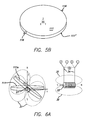
- FIG. 5 is a pair of drawings—“A” and “B” views like FIGS. 4A and 4I respectively—but for a circular production mirror rather than the octagonal prototype;
- FIG. 6 is a pair of drawings showing an electromagnetic drive for the FIG. 4 production mirrors—the “A” view being a conceptual sketch showing operational principles; and the “B” view being generally like FIG. 1B (but for a production system);
- FIG. 7 is a longitudinal-section (i. e., taken in a plane along the central axis) of a “vee”-style (i. e., “V-shaped” in longitudinal section) jewel bearing;
- FIG. 8 is a perspective view of two stainless-steel pivots for use with the FIG. 12 bearing;
- FIG. 9 is an elevation of a ring-style bearing, shown with a shaft and an end stone—with the ring itself in longitudinal section;
- FIG. 10 is a set of mechanical layouts—namely one common front view and seven different side views in longitudinal section—for jewel (e. g. sapphire) bushings having seven corresponding different shapes, namely (from left): straight hole, “olive” hole (having a curved longitudinal section), “bombé” face (having a curved cross-section) with straight hole, bombéface with olive hole, oil-cup face with olive hole, oil-cup face with straight hole, and double-cup faces with straight hole, respectively;
- jewel e. g. sapphire
- FIG. 10 is a set of mechanical layouts—namely one common front view and seven different side views in longitudinal section—for jewel (e. g. sapphire) bushings having seven corresponding different shapes, namely (from left): straight hole, “olive” hole (having a curved longitudinal section), “bombé” face (having a curved cross-section) with straight hole, bombéface with olive hole, oil-cup face with olive hole, oil-cup
- FIG. 11 is a graph of mirror acceleration vs. mirror thickness in meters, for driving current of one ampere is through 200 windings;
- FIG. 12 is an electrical schematic, somewhat conceptual, of a circuit for closed-loop control of a scan mirror—the schematic being juxtaposed with a drive-apparatus drawing like FIG. 6B ;
- FIG. 13 is a basic conceptual diagram of three-dimensional geometry for a steerable mirror as shown in FIGS. 1 through 10 ;
- FIG. 14 is a like diagram indicating how mirror angular position is monitored by an embodiment of our invention that uses an areal detector and a reflector at the back surface (not used for beam steering) of a steering mirror;
- FIG. 15 is a like diagram indicating how mirror angular position is monitored by an alternative embodiment that uses a pair of retroreflectors at the back surface of the mirror, with a fringe-counting laser interferometer;
- FIG. 16 is a like diagram showing detail of the FIG. 15 interferometer
- FIG. 17 is a conceptual perspective representation of an operational implementation of a roving foveal sensor, capable of simultaneously generating a wide-FOV (or wide-FOR) image and a narrow-FOV image (see inset view)—both at high resolution—with the corresponding narrow-FOV image inset into the wide-FOR (or wide-FOV) image, making a composite output view; and further showing a preferred embodiment of the invention collecting those two images; and more specifically the drawing shows general-aviation collision avoidance;
- FIG. 18 is an optical diagram, somewhat conceptual, of the roving foveal design—one of three configurations that each include a beam splitter for picking off a large-FOR “staring” detector from inside an afocal optical assembly; is but here more specifically the drawing showing a preferred configuration in which a narrow-FOV image is movable with respect to the wider-FOV or FOR image, for viewing, so that an inset narrow-FOV image can be placed—relative to the wider image—as preferred by an operator or system designer, and indeed can be moved about, in relation to the wider image, in real time;
- FIG. 19 is an exemplary optical design schematic of a color-corrected afocal optical system according to a preferred embodiment of the invention, for operation with visible light;
- FIG. 20 is an operational flow chart, highly schematic and showing methods—according to our invention—that also make use of MEMS mirrors of that same new generation;
- FIG. 21 is a block diagram, with most portions symbolically in side elevation but certain other portions (an aperture-lens assembly 14 and a lens/detector assembly 22 ) symbolically in isometric projection, of a basic first function—namely, a detection function—for preferred apparatus embodiments of the invention;
- a detection function for preferred apparatus embodiments of the invention
- FIG. 21A is a like diagram, but having no afocal element at all—and capable of operation over a relatively large field of regard solely by virtue of operating a steering mirror over a sufficiently large mechanical-deflection range to achieve a sufficiently large optical-deflection range;
- FIG. 22 is a like diagram showing an extension of the preferred apparatus embodiments to encompass a second function, namely optical analysis
- FIG. 23 is another like diagram but now showing a further extension to encompass dual forms of yet a third function, namely response;
- FIG. 24 is a multiapplication block diagram representing apparatus and procedures, using the apparatus embodiments of FIGS. 21 through 23 for the above-mentioned and other functions, and in a number of variegated applications;
- FIG. 25 is a diagram generally like FIGS. 21 through 23 but with the lens and detector assemblies 14 , 22 enlarged for presentation of details;
- FIG. 26 is a diagram conceptually representing a spiral-scanning raster pattern for use in any of the FIG. 21 through FIG. 25 systems and methods;
- FIG. 27 is a detailed top plan, somewhat schematic, of a prior-art MEMS mirror assembly with integral gimbal system—and showing direction of a magnetic-excitation field (after the “prior art” FIG. 2 in the above-discussed '921 patent of Bernstein, Taylor et al.);
- FIG. 28 is a simplified view of the same assembly, together with magnets for imposing such excitation (after “prior art” FIG. 3 in the same patent);
- FIG. 29 is a like view, but of a first part of an embodiment of the invention that is taught in the '921 patent (after FIG. 8A in the same patent), having separate “X-axis control coils” on the mirror pad, at opposite sides of the horizontal flexure and associated rotation axis—and is prior art with respect to this present patent document, but not with respect to the '921 patent;
- FIG. 30 is a like view of a second part of the same embodiment (after FIG. 8B in the same patent), but instead having separate “Y-axis control coils” on the mirror pad, at opposite sides of the vertical flexure and associated axis—likewise prior art with respect to this document but not to the '921 patent;
- FIG. 31 is a system diagram, highly schematic, showing aspects of our invention that incorporate one or more MEMS mirrors of the “new generation” discussed in the “BACKGROUND” section of this document (see related notes following this list);
- FIG. 32 is a like diagram of two representative FIG. 31 mirrors in an end-to-end array and with the FIG. 31 base, but now seen edge-on and particularly shown with the mirrors rotated away from the common base angle (here forty-five degrees) by an arbitrary, illustrative amount (roughly nine degrees); and further with one of the mirrors adjusted also in piston, to a position 112 ′ as shown in the broken line, for reasons explained herein;
- FIG. 33 is a plan view of a magnetic circuit used in certain of our FSM control-system experiments described in this document;
- FIG. 34 is a simplified “electrical” model of the FIG. 33 magnetic circuit
- FIG. 35 is a graph of flux density generated by our FIG. 33 FSM magnetic circuit, as a function of current;
- FIG. 36 is a top plan view of the mirror, together with one “mu-metal” arm used in the same magnetic circuit;
- FIG. 37 is a pair of diagrams, quite schematic, defining some parameters (magnetic field, coil length and coil circumference, of a magnetic-field coil with an air core—used in certain variants of the FIG. 33 circuit;
- FIG. 38 is a like diagram defining relationships between magnetic moment and torque, for the same circuit.
- FIG. 39 is a graph of the torque developed at the mirror, as a function of number of ampere-turns in the driving coil
- FIG. 40 is a plot of resulting response times for a 10-mm mirror and magnet (with no magnetic-circuit ring around the magnet), as a function of magnet thickness in meters;
- FIG. 41 is a perspective view of a prototype of the FIG. 33 magnetic circuit, assembled to our experimental structure—with a Hall-effect sensor under the intended position of the mirror;
- FIG. 42 is a like view of the prototype on our experimental bench with electronic modules ready for use;
- FIG. 43 is a set of five views of diverse prototype magnetic circuits used in the FIG. 42 experiments.
- FIG. 44 is a graph of flux density vs. electrical current, in amperes, through the coils.
- FIGS. 1 through 5 , 7 through 10 , 12 , 18 , 19 , 33 , and 41 through 43 are very generally to scale.
- FIG. 31 for the sake of simplicity, mirror control coils and resulting forces are explicitly illustrated for only a single axis of rotation. It is to be understood that the coils and forces are closely analogous for the orthogonal direction, just as illustrated in FIGS. 29 and 30 respectively.
- one of the rotational directions is managed by use of a MEMS or FSM steering frame (not shown) surrounding the mirror pad and carrying coils for driving in that direction, as shown in FIG. 27 and discussed in the above-mentioned patent documents of Bernstein and Taylor.
- dual-axis rotation of a single mirror-carrying element can be substituted, as also described in those documents.
- FIG. 31 is meant to represent both these kinds of dual-axis implementation, and also several other system variants as more fully detailed below.
- FIG. 31 portions of FIG. 31 are representative of a single electromagnetically controlled mirror 311 with a rotational axis 317 ; or equally well of an end-to-end two-mirror array 311 , 312 with spaced-apart rotational axes 317 , 318 ; or also equally well representative of a side-by-side two-mirror array 311 , 314 with axis 317 —or 312 , 315 with like axis 318 , etc.—or of a larger array such as the six-mirror assembly 311 - 316 expressly shown.
- the coils e. g. 311 c , 311 d , in cooperation with magnets that may e. g.
- FIG. 31 also includes an auxiliary optical system 331 - 339 for purposes related to optimizing imaging sharpness, as detailed below.
- the drawing further includes a generalized element 351 , which represents any of several supporting or utilization devices, or combinations of such devices, that are advantageously incorporated into the system. The possible devices are enumerated and discussed in following sections of this document.
- Preferred embodiments of our invention provide an optically agile imaging system, with related methods, based upon certain active optical components—in combination with a servoed-beam-steering subsystem according to the coowned patent documents listed earlier.
- the result encompasses a small, lightweight and relatively economical sensor technology.
- the resulting capabilities enable e. g. commercial air traffic systems, astronautical operations and military agencies to enjoy very greatly enhanced but low-cost imaging—including persistent surveillance and pointing.
- Advanced imaging using electronically addressable pointing and imaging capability without a conventional gimbal, enclosing the entire optical system, provides the basis for lightweight, low-power, reliable imaging performance.
- refractory adheres to conventional definitions in engineering etc., namely materials that are difficult to work, or that are extremely hard, or sometimes that have a high melting point or are “difficult” to melt.
- refractory bearings include, without limitation: ceramics, cast materials such as used in making tiles and furnace linings, some types of concrete or cement, gemstones, synthetic gems (including original Hart artificial diamonds), and other tough minerals.
- Related classes of potentially useful materials are refractory plastics, known in the marketplace, and refractory metals such as tungsten, molybdenum and alloys. Most such plastics, however, at present are inadequately stable for our purposes—particularly under heat or relatively high stress.
- the PVD site discusses molybdenum disulphide, said to have “an ultra low coefficient of friction (0.01-0.06)”.
- the “EnduraCoatings” links relate to composite diamond coating.
- this invention can be implemented with zero rotational restoring force, so that rotational position tends to be quite stable without application of large continuing positional force.
- rotational position tends to be quite stable without application of large continuing positional force.
- mirror magnetically we prefer to drive the mirror magnetically as detailed below; however, other rotational drive arrangements are readily available.
- the mirror has a permanent magnetic field along the Z axis ( FIGS. 12 through 15 , and 37 ). This field facilitates rotating the mirror about the local X and Y axes by application of current to nearby electric coils, resulting in respective magnetic fields. The fields interact with the permanent Z-axis field to create torque, impelling the mirror about the X and Y axes.
- the one or more electromagnetic coils 12 ( FIGS. 1 and 12 ), 21 ( FIG. 6B ), 412 a - d ( FIG. 33 ) are switched or modulated (or both) to create attractive and repulsive magnetic forces that result in a net torque on the scan mirror ( FIG. 38 ). Switching between positive and negative voltages reverses current through the coils, providing magnetic field of desired direction. Additionally, one or more coils can be simultaneously switched to a “brake” terminal B that electrically completes the coil conduction path—resulting in back-emf that brakes the rotating mirror, e. g. about q X .
- the steering module ( FIGS. 4A through 4E , and 5 A), allowing for rotation in two axes, comprises three major components: the mirror subassembly 11 , 16 , 18 , 25 (see also FIGS. 4F , 4 I and 5 B), inner ring 15 , 14 , 19 , 15 (see also FIG. 4G ), and outer ring 13 , 17 , 24 , 19 , 27 (see also FIG. 4H ).
- the mirror subassembly rotates on two opposing pivot points 16 , 19 inside the inner ring.
- the mirror subassembly and inner ring rotate about another set of pivot points 14 , 19 ′ between the inner and outer rings and mounted at right-angles to the pivot points between the mirror subassembly and inner ring—thus providing independent orthogonal rotations of the mirror.
- the mirror subassembly is driven in rotation by a set of four or more electromagnetic coils 12 , 21 , 412 a - d mounted around the perimeter of the steering mirror as noted above.
- the angular range is very small, at best three degrees on only one axis.
- the preferred jewel-bearing and equivalent embodiments of our invention are—by design—able to achieve mechanical-excursion angles exceeding 25 degrees in both axes.
- a jewel-bearing design also provides large apertures, from seven millimeters to three and even five centimeters, which are not practical with the silicon torsion-flexure design.
- Our invention contemplates still-higher apertures, to the order of e. g. ten centimeters and more, without major modifications in design considerations or scaling techniques.
- the mirror subassembly 25 ( FIG. 4E ) comprised a ten-millimeter octagonal mirror 11 of silica, a seven-millimeter grade-N50 neodymium magnet 18 , and an axle 16 made of 300-series stainless steel—bonded together with epoxy.
- the production version of the mirror subassembly contemplates simplifying the design by combining the mirror and magnet into one piece ( FIGS. 4I , 5 A, 5 B).
- the production mirror consists of a magnetic material (grade-N50 neodymium)—plated and then polished to an optical-grade mirror finish, optionally on both sides. (Being symmetrical, such a mirror cannot be installed “upside down”.)
- This design allows alignment of the pivot points with the magnet CG.
- the back of the mirror, in this configuration, can be used as part of an optical-position sensor for the control feedback loop.
- the mirror pivots form a nonmagnetic axle that rides in a bearing 19 ( FIG. 4A ).
- the axle pins 16 can be made part of the mirror assembly 25 and the bearings 19 part of the inner ring 15 ( FIGS. 4A. 4B ) or vice versa, as preferred.
- pivot points can be attached to an additional intermediate structure.
- the mirror/magnet can be mounted to that additional structure.
- the natural resonant frequency of our mirror/magnet assembly is roughly two kilohertz.
- the driven response bandwidth is typically one hundred to two hundred hertz, but much higher (e. g. one kilohertz) with refined control-system design and components.
- I NNER RING The inner ring plays a key role in the design. In our prototype it is an aluminum ring approximately 12 mm in diameter and 2 mm thick. It also contains pivot points for both the mirror subassembly and the inner ring itself, allowing the mirror to rotate about both axes.
- the inner ring shown is a prototype. We may elect to change the shape and pivot configuration for the production version—for example to provide spring preload for the pivot points.
- the ring can be made of nonmagnetic material such as an aluminum alloy, beryllium, beryllium-copper, titanium alloy, tungsten, 300-series stainless steel, silica or other suitable substance.
- the outer ring 13 ( FIGS. 4E , 4 H) has two primary functions: it mounts the overall steering-mirror assembly to the base structure 23 ( FIG. 1B ), and holds one side of the pivots for the inner ring. In the production version we will either enlarge it or remove it completely, so that the electromagnetic coils 12 , 21 can be mounted closer to the mirror assembly and thereby increase the torque that the electromagnets can apply to the mirror assembly.
- P IVOT POINTS ( JEWEL BEARINGS )—Two suitable jewel-bearing configurations are the “vee” ( FIG. 7 ) and “ring” ( FIGS. 9 and 10 ).
- Our prototype incorporates a vee bearing for both pivots; however, ring bearings are more rugged and may be preferred for final construction.
- the vee configuration uses nonmagnetic stainless-steel pivots ( FIG. 8 ) that ride in vee bearings. These various components are used in precision instruments such as analog ohm/voltmeters and compasses, but never heretofore in steering-mirror systems.
- the ring configuration has a steel shaft that rides in e. g. a ring-shaped sapphire bushing 119 a ( FIG. 9 ) and is held in place axially with a sapphire endstone 119 b .
- the endstone is spring loaded.
- the latter arrangement is commonly used for light-shock applications; a silicone cushion, for high-shock loads up to 1000 g's.
- a ring jewel with an “olive” hole 142 ( FIG. 10 , hole with radius) offers lower friction. The radius surface of the hole provides minimum contact with the pivot, and thereby minimum friction.
- T WO - AXIS TIP/TILT SENSOR We prefer to use a local tip/tilt sensor, which measures q X and q Y position, velocity or acceleration, in a negative-feedback control loop 52 ( FIG. 12 ). This local feedback is combined with inertial feedback 53 , and subtracted from the desired angular position, velocity or acceleration command 51 .
- a position, integral, derivative (“PID”) or other suitable controller For each rotational degree of freedom, this difference is provided to the controller—a position, integral, derivative (“PID”) or other suitable controller.
- Resulting electromagnetic-coil commands (currents) 58 are then provided to the coils 12 , driving the mirror by magnetically induced torque.
- Preferred embodiments of our invention contemplate two approaches—primarily alternatives—for a sensor to measure changes in angle about the two rotational axes of a mirror.
- a sensor to measure changes in angle about the two rotational axes of a mirror.
- access to the back of the mirror is required, but the front (beam-steering reflective surface) of the mirror is left unobscured.
- the mirror can rotate 62, 61 about two nominally orthogonal axes, X and Y ( FIG. 13 ), relative to the front reflecting surface whose normal is Z.
- a laser source 63 FIG. 14
- This element reflects the laser-source beam 63 along a path 64 toward a two-dimensional (“2-D”) areal detector 65 .
- This detector could be a position sensing detector, a quad detector or a detector array with multiple elements.
- the areal detector 65 measures the location (x′, y′) of the reflected laser beam 64 onto a plane parallel to the original nonrotated X-Y mirror plane X′, Y′. As the mirror rotates about the X and/or Y axis the angular rotation about q X and q Y can be estimated, given knowledge of the (x′,y′) detector measurement and knowledge of the distance Z′ from the mirror.
- the distance of the mirror reflective surface from the center of rotation establishes the denominator for a sine or cosine effect.
- the second preferred measurement approach uses a retroreflector interferometer pair 111 a , 111 b ( FIG. 15 ) that measures the change in relative distance Z′ 2 , Z′′ 1 between fringe-counting interferometers 65 a , 65 b and the retroreflectors 111 a , 111 b respectively.
- the retroreflectors are attached to the back of the mirror 111 ; and the interferometers, to a fixed base (not shown).
- this system finds the rotational angle q X about the X axis—as equal to arctan((Z′′ 1 ⁇ Z′′ 2 )/Y′′ 1-2 .
- a third retroreflector interferometer set (not shown) that is not in line with the first pair 65 a , 65 b can be used with one or both of those other sets to measure rotation q Y about the Y axis.
- a three-set configuration can also be used to measure displacements, in Z, of the plane containing the three retroreflective elements 111 a , 111 b .
- the retroreflective elements can include a sphere or cubical corner, which reflects entering light to leave the reflector parallel to the incoming light-propagation vector.
- Each fringe-counting interferometer 65 a , 65 b preferably a Twyman-Green configuration ( FIG. 16 ), includes a laser 63 that directs a beam 63 a to the front side of a splitter 67 . Part of that beam 63 a is reflected upward along a first path 69 a to the retroreflector 111 a or 111 b , where that part of the beam is returned downward along a parallel path 69 b , this time back through the splitter, to a detector 68 .
- the remainder 63 a ′ of the original beam 63 a is reflected from the fixed mirror 67 , along a return path 64 a , 64 b to the back side of the splitter 67 and then downward along a path 69 b to the detector.
- the interferometers measure change in Z, Z′′ etc. based on knowledge of the laser 63 wavelength—and based on counting fringes as light propagating along the moving paths 69 b reflected from the retroreflectors 111 a , 111 b interferes with the fixed-path returns 64 a , 64 b from the fixed mirrors 67 in the interferometers.
- the starting material is a thick silicon-on-insulator (“SOI”) wafer layer—on a 300 ⁇ m handle wafer, separated by oxide 1 ⁇ m thick.
- SOI silicon-on-insulator
- a metal mirror is deposited by sputtering, followed by liftoff.
- ICP Inductively coupled plasma
- etching steps define the mirror, torsional springs, and monosilicon gimbal.
- a second plasma-etching step removes the handle wafer so that the mirror can move.
- the thickness of the springs and mirror is established by the thickness of the starting SOI material.
- a magnet preferably a permanent magnet inserted in a cavity in the silicon mirror enables light-deflecting actuation about two axes by a set of four drive coils.
- Positional feedback sensing for the mirror comes from the output of sensors such as PSDs, as described above, so that the deflection angle is determined by monitoring mirror-control signals. Sensitivity for this feedback is related to the operating principles of both the sensor and the above-mentioned mirror drive magnet. Full understanding of the feedback-sensitivity subsystem is a primary determinant of potential overall system performance.
- MEMS-type mirrors may not perform as expected. For example, they may not rotate as far as desired or may be too fragile for a high-shock and -vibration environment—even after flexure optimization. Additionally, feedback sensors may not give sufficient positional accuracy for adequate closed-loop mirror control. As noted elsewhere in this document, such torsional-flexure mirrors (especially when large) are subject to bending out of plane; such distortion in turn leads to beam divergence and “splatter”—i. e., waste of substantial fractions of the beam power that are misdirected away from the nominal beam direction. To address these risks, we recommend initially fabricating a 10-mm (or larger) servoed mirror and fully characterizing its performance. Particularly advisable is demonstration of hemispherical pointing in both open- and closed-control-loop environments.
- C ONTROL - SUBSYSTEM CONSIDERATIONS Demonstrating performance at the system level entails tests of so-called “persistent surveillance tracking” (step-stare and platform dynamics) with INS (inertial navigation system) feedback. Such investigation can be conducted in the laboratory with simulated platform motion. Specifically, it is helpful to integrate signals from mirror-position sensors with inertial data.
- One low-risk approach to achieving this goal is to first establish open-loop control of the mirrors (i. e. without using mirror-feedback sensors). Hemispherical beam steering can then be demonstrated, with ability to project a beam through a commercial wide-FOV afocal lens to achieve the hemispherical beam steering, through integration of a simple visible laser.
- the next objective should be closing the pointing control loop.
- closed-loop control and stability can be characterized easily.
- a final step can be incorporating inertial-sensor feedback, to demonstrate closed-loop stabilization relative to an inertial reference frame. Mounting the system on a platform with known vibration dynamics can facilitate obtaining full characterization of the inertially stabilized system.
- beam-deflector arrays or individual mirrors exceeding 10 cm may not be of interest now. This is so because modules of 10 and even 5 cm appear to fully satisfy current objectives, and very different solutions are available where bigger systems are desired. Nevertheless it appears that larger units are fully functional; therefore they remain of interest for technical applications that may become more-interesting in the future. Such applications may relate e. g. to high apertures for high-energy response beams.
- the present invention partly consists of introducing very large nonMEMS mirrors, nonplanar-silicon etched mirrors, and nontorsional-flexure steering mirrors.
- the invention is not limited, however, to active systems. As seen elsewhere in this document, certain aspects of the invention have important applications in passive optical systems.
- some very useful embodiments of our invention include no afocal element.
- our newest refractory-bearing steering mirrors have such a very wide scanning angle, in most cases we are able to obtain adequate field of regard without an enlarging afocal element.
- an afocal element can still be useful, operated in a reducing mode, to achieve very valuable finer pointing precision and thereby more precise steering.
- taking a reduction ratio of 5:1 in an afocal element can refine the precision of pointing from e. g. 100 ⁇ rad down to 20 ⁇ rad.
- the optic can be used in such a mode exclusively, if for instance the system designers and operators are confident that no enlarging usage will be meaningful for their particular combination of circumstances, applications, etc.;
- the optic can be used in both reducing and magnifying modes at will, e. g. in alternation, if the designers and operators see utility in providing such a varying capability.
- some preferred embodiments of our invention comprise optical systems that are passive—meaning that they simply receive and analyze an incoming external optical beam, without either:
- F AST SCANNING MIRROR BEARING CONFIGURATIONS Configuration of the bearings used for a fast scanning mirror should not be restricted to the use of jewel bearings. Many bearing types could be used depending on the application and mirror size. The single most-important property of the bearing evidently is low friction. The smaller the mirror, the more significant the friction becomes. Increase of mirror diameter requires larger forces to move the mirror due to the increase in inertia. The equivalent torque corresponding to bearing friction thus becomes a smaller portion of total torque required to move the mirror at high accelerations. As the mirror size increases, the number of options for bearings increases. Some of the bearings that may be useful in FSM designs are described below; this listing is not intended to be exhaustive.
- Static and dynamic friction should be considered in selecting a bearing.
- Low static friction sometimes called “breakaway” friction or “stiction” is required in applications where pointing stability is important.
- the best friction level varies with practical applications contemplated, with bearing type, and with size and mass of the mirror, magnet etc.
- An overall objective is to find the most-favorable compromise between mirror stability and speed (i. e. bandwidth) of pointing or steering response.
- FSM fast scanning mirror
- a fast scanning mirror using our jewel bearings and their ceramic and other refractory equivalents—at a mirror diameter of 10 mm as implemented according to the present document—our measurements to-date indicate that such a best compromise results from a coefficient of friction within the range 0.1 to 0.15 (dimensionless).
- friction typically is extremely low but varies (at least for high mirror-rotation speeds) with the square of velocity. Accordingly very different parametric values and control considerations typically obtain.
- any differential-equation analysis using a classical imaginary-number coordinate system tends to “blow up”. That is, the so-called “poles” and “zeroes” of such an analysis typically tend to line up along the imaginary-number axis—a mathematical behavior that in the physical world corresponds to uncontrollable instability.
- C ERAMIC BEARINGS These are similar to jewel bearings, but their hard, low-friction surfaces can be formed into many shapes and bearing configurations. Thus ceramic bearings can be customized to meet particular needs of a variety of applications.
- L OW - FRICTION COATINGS These coatings are very versatile, especially in bearings for larger mirror sizes, as they can be applied to almost any surface, especially almost any machined surface. Low-friction coatings are applied by dipping, spraying or—perhaps most promisingly—vapor-phase deposition. Coating thickness can vary from 2 to 100 ⁇ m. A particularly advantageous construction may result from simply spraying or otherwise coating such suitable ceramic, or other refractory materials, into a hole or some to other constraining structure. Properties of such a hole or other structure, and other details of refractories design and use, can be learned straightforwardly from vendors, for example in vendor websites such as identified above.
- a IR BEARINGS Such bearings consist of an air flow, or air in a sealed chamber, that supports a shaft or other movable (particularly rotary) element. Air bearings have low breakaway friction, and very low friction in general. They would be most straightforward and therefore most appropriate for the outer stage of our mirror support. A bearing for the inner, gimbal-like stage would require an air supply to the bearing over the outer rotation axis. An air bearing also requires large bearing surfaces, which would restrict use at the inner stage because of the corresponding increase in material and inertia.
- Friction arising in air bearings calls for a different analysis than in jewel and other-refractory bearings.
- mirrors and mirror/magnet assemblies exhibit air friction that changes very strongly with velocity through the gas.
- dominant behavior is quadratic variation with velocity. Modeling systems with such variation is feasible and should be performed before attempting to build a steering mirror with air bearings.
- FSM F AST SCANNING MIRROR
- FIG. 11 Increase in thickness of the mirror magnet has a diminishing return ( FIG. 11 ).
- the functions graphed in FIGS. 11 and 40 strongly imply that maximum torque and minimum response time call for an optimum thickness—generally about 2.3 mm—for the magnet/mirror assembly; however, it must be recognized that these graphs apply only for a particular value (one centimeter) of diameter, for the assembly. This fact leads to a need for detailed consideration of scaling, which will be introduced very shortly. As will be understood from such details, determining optimum geometries is moderately complicated—but can be brought under control using the analytical framework presented in this document.
- the drive mechanism is primarily useful for relatively small mirror applications, involving diameters e. g. below 5 cm.
- the drive efficiency for larger mirrors can be improved with more-conventional on-axis drive motors.
- the torque required to drive the mirror at the same rate increases by, very roughly, the third power of the diameter.
- the mirror/magnet inertia typically rises with the fourth power of their diameter—driving up the response time—but response also falls linearly with the mirror/magnet diameter, due to the radius on their disc where force or torque is normally applied.
- the net effect of these two opposing tendencies is, roughly, an increase in response time with the diameter cubed—i. e., to for increase from 1 to 2 cm diameter, nominally an eightfold increase in response time.
- the magnet/mirror itself may be circular, as indicated elsewhere in this document. Instead, and preferably, that assembly may be elliptical so that it presents a substantially circular profile when partly rotated out of the plane of the overall structure—particularly when viewed along the normal to that structure. Such out-of-plane effects can be exploited to maximize torque and thus minimize response time when the mirror is at angles that demand highest torque for good response time.
- the magnet/mirror assembly is circular, its adjacent air gaps are best minimized by forming spherical surfaces at the inboard ends of the radial arms, to match the three-dimensional surface swept out by those arm ends. If instead the assembly is elliptical as noted just above, then a more-sophisticated ellipsoidal surface at the inboard arm ends makes a better match.
- the feedback design of our preferred sensor has been described as a position sensing detector (“PSD”).
- PSD position sensing detector
- the mirror-position feedback device can be any type of device that provides the required resolution and dynamic response for the desired application. Some such devices are photodetector arrays, linear CCD arrays and the like.
- FSM fast scanning mirrors
- the magnetic-circuit model is a physically accurate, realistic representation of the apparatus that makes up our preferred FSM steering assembly. It includes a central, circular permanent magnet 411 ( FIG. 33 ), preferably sintered NdFeB.
- each coil 412 is wound on a respective radial mu-metal core.
- the cores 412 are each 6.35 mm in diameter, and separating each core from the central magnet is a 1.53-mm air gap 413 .
- This feedback path 416 Disposed circumferentially around the four prototype cores, with their coils, is an octagonal mu-metal magnetic feedback path 416 with square cross-section, 6.35 mm across and 6.35 mm tall.
- This feedback path 416 (familiarly designated the “racetrack”) is in intimate contact with the outboard ends of the four cores 412 , and carries magnetic flux 414 between the several core ends.
- magnetic flux from the outward end of a representative core 412 a flows to the racetrack 416 , dividing itself into clockwise and counterclockwise paths 415 to the diametral core, i. e. to the aligned core 412 d at the far side of the magnet.
- the flux then proceeds through that latter core 412 d radially inward—across the associated air gap—to the central magnet.
- the length of one such return path 415 (i. e. either a clockwise or a counterclockwise path) from air gap to air gap, in our prototype preferred embodiment, is 102 mm.
- the flux bypasses the pair of intermediate cores 412 b , 412 c that are at right angles to the two mutually diametral cores 412 a , 412 d just mentioned.
- the above magnetic circuit for a helpful visualization of its operation can be modeled mathematically as an “electrical” circuit.
- the electromagnet around the mu-metal core is modeled as a voltage source Ni ( FIG. 34 ) with a resistor R c in series.
- the air gaps are modeled as resistors R g ; and the permanent magnet, as a current source ⁇ r with a resistor R m in parallel.
- the core reluctance (R c ) is given as:
- each radial core or “arm” 412 subtends an angle ⁇ ( FIG. 36 ):
- ⁇ 2 ⁇ sin - 1 ⁇ ( w c 2 ⁇ r c ) .
- FSM P ERFORMANCE E STIMATES To find the angular acceleration of the mirror, we divide the torque by the combined inertia of the magnet and mirror. The inertia increases with the magnet/mirror thickness quadratically; and the torque, linearly. The mirror inertia, however, is greater than that of the magnet.
- the illustrated function is applicable to a mirror and magnet of diameter 10 mm. These acceleration figures can be used to determine the achievable response time ( FIG. 40 ). This graph, too, applies to a 10 mm mirror and magnet, with no ring around the magnet.
- E LECTROMAGNET P ERFORMANCE E XPERIMENTS The goal of this work was to compare several diverse magnetic-feedback coil designs to one another. For most-meaningful comparisons, we wanted the geometries (in particular the air-gap sizes) for the several coil types to be substantially identical. This was accomplished using a test structure (or “jig”) 421 ( FIG. 41 ) quickly made on a so-called “3D printer”.
- Such a “3D printer” device is a variant of a stereo-lithography machine that extrudes layers of plastic. (Ours uses the type of plastic known as “ABS”, rather than curing resin.) It is commercially available as Model SST-1200 from the company Stratasys, Inc.—sometimes instead called Dimension, Inc.—of Eden Prairie, Minn. People skilled in this field will understand that many other ways of preparing our test structure could produce wholly equivalent results.
- a Hall-effect sensor 424 (used to measure the flux-density strength) was locked in place relative to the representative test coils 412 a , 412 b —within a recess 422 formed in the jig 421 .
- Three screws 423 held the octagonal magnetic circuit 416 or “racetrack” to the jig; and we used two-part epoxy adhesive 435 a , 435 b ( FIG. 42 ) to held the coils 412 a , 412 d and sensor 424 to the jig 421 .
- the coils were driven with a current-limited power supply 433 ( FIG. 42 ).
- the Hall-effect sensor 424 was driven by a separate power supply 432 , and the sensor output monitored with an oscilloscope 431 .
- a test module 410 e ( FIGS. 41 through 43 ) comprising the two-hundred-winding test coils and the octagonal racetrack 416 , was supported on the jig 421 ; and the latter was in turn placed on a tabletop 420 .
- Two mating test-coil modules 410 c ( FIG. 43 , at left and right) of another design—the mu-metal core with a second-generation (“GenII”) return, discussed below—were also similarly mounted and tested. Each controlled a respective one of the two mirror-rotation axes.
- Yet another tested module 410 d had hundred-winding coils.
- step 1 Return to step 1 and iterate for a new current setting.
- a FOCAL B EAM S TEERING An important category of systems enhanced and facilitated by preferred embodiments of our present invention is the category previously known as “AMBS” (afocal MEMS beam-steering) systems. As pointed out earlier in this document, however, the present invention sweeps more broadly than MEMS (microelectromechanical systems).
- Preferred embodiments of the present invention in general favor the jewel-bearing construction that—as noted above—has far better response characteristics, including dynamic range. Also strongly preferred are the other low-friction bearings discussed above.
- Afocal optics to enlarge or reduce the field of regard, however, remains a particularly valuable feature of the preferred embodiments. Since those embodiments encompass both MEMS and nonMEMS steering systems, the acronym “AMBS” is now best modified by dropping the “M”—leaving simply “ABS” for “afocal beam steering”. The advantages of this feature, already set forth in other patent documents of our coowned series, will be reprised now.
- the invention provides a low-cost sensor system 210 ( FIG. 21 ) capable of detecting and locating active illumination sources—or objects illuminated by such sources.
- the sensor system of the invention can also respond to the detected light source by returning a light beam 238 ( FIG. 23 ) or even an object, and in some cases by initiating a distance-determining or other investigation (Function 4 , FIG. 24 ) of the source or objects associated with the source.
- initial detection of a radiation source or illuminated object is qualified by filters that implement expectations as to the characteristics of such sources or objects that are of interest. For instance, when anticipated sources are infrared, or are in other particular spectral regions, spectral filters are placed at convenient positions in the optical path—usually but not necessarily associated with the fold mirror 221 , and in particular taking the form of bandpass optical reflection/transmission filters.
- incoming radiation 213 A ( FIG. 21A ) from a representative source 201 A proceeds directly to the steering mirror 215 A, 216 A.
- the mirror control system 226 A is calibrated appropriately for the different relationships between mirror angle and external pointing direction, in the absence of an afocal element.
- the fold mirror 221 ( FIG. 21 ), FIG. 221A ( FIG. 21A ) can be advantageously implemented as a beam splitter, and incident-beam selectivity is simply an additional one of such purposes.
- a dichroic or other bandpass or bandblocking filter can be used, as an alternative to a fold mirror 221 .
- the filter transmits these undesired components to a radiation sink or to an auxiliary is detection system 255 , while reflecting the desired radiation components to the detector—or conversely, depending on preferred system configuration.
- Such advance filtering is not limited to spectral characteristics.
- the signal 225 from the optoelectronic detector 224 is advantageously filtered electronically 256 to exclude d. c. sources or sources having no significant bandwidth activity above a specific threshold frequency—or, more restrictively, to pass only a. c. signals having a particular specified modulation pattern or class of patterns.
- the system detector 224 is a PSD, which has the ability to report positional coordinates ⁇ X , ⁇ Y (on the PSD's own surface 225 ) of an impinging optical beam from a source 201 in a region without the necessity of scanning the region. As noted elsewhere in this document, it is also necessary to determine the mirror position. From these data and known characteristics of associated optics, as explained above, angular position ⁇ X , ⁇ X of the source is readily calculated.
- a PSD is nonlinear and temperature sensitive when measuring large off-axis coordinates ⁇ X , ⁇ Y and thus angles ⁇ X , ⁇ Y .
- Such drawbacks are neutralized, in preferred forms of the present invention, by operating in a null-balance mode as detailed below—so that the system relies on the PSD primarily only to determine whether the source is off axis and, if so, then in which direction; and not for quantitative reporting of large off-axis coordinates or their associated angles.
- the system After the sensor system (including the arithmetic preprocessing mentioned earlier) has determined initial values for the incident angles ⁇ X , ⁇ Y , the system very rapidly servocontrols itself to keep incident rays 213 at the center of the detector field.
- Most preferably such servocontrol 227 is implemented by one or more microelectromechanical (MEMS) mirrors or fast scanning mirrors (FSM) 215 disposed inside the optical system 210 , i. e. along the optical path between the detector 224 and the collecting aperture 214 , 245 ( FIG. 25 ) of the system.
- MEMS microelectromechanical
- FSM fast scanning mirrors
- Such mirrors have extraordinarily low mass and inertia, and corresponding extremely high response speed—thus obviating the problem of sluggish response in earlier systems. Additional observations as to the new, larger MEMS or FSM mirrors appear later in this section. Placing the mirror or mirrors inside the system gains yet further advantages of angular displacement speed, in the visible volume 211 of space outside the optical system, particularly if a lens 245 is placed at the aperture to optically magnify the angular displacement of the mirrors.
- This particular arrangement for servocontrol of the incoming light, to center the beam on the detector, is particularly advantageous when using a PSD. Whereas that type of detector measures large off-axis angles somewhat inaccurately, the system is easily made extremely accurate in measuring the angular correction 228 applied by the MEMS or FSM system to bring the source to the central, null position.
- ⁇ X , ⁇ Y has been used to represent both the off-axis angle of the beam 213 ( FIG. 21 ) and the mirror-orientation 216 signals 228 relative to nominal or rest positions of the mirror or mirrors 215 .
- these two different sets of angles 213 , 228 are not at all the same—but when the system has servocontrolled itself to null the incident beam at the center of the detector 224 , the two sets are related by straightforward transforms.
- Such transforms include the magnification factor introduced by the afocal package 214 , as discussed at length elsewhere in this document, and also include the local calibration of the mirror actuator-stem positions relative to an internal standard, and also distortion in the afocal array 214 as well as the final focusing optic 223 , and so forth.
- the PSD itself can effectively monitor a far larger angular region 211 than it can image. This is a major advantage never fully exploited in conventional systems because of failure to use internal mirrors, or very small mirrors, and because of failure to servo the input source to a reproducible centerpoint on the detector.
- This combination of the intrinsic angular-dynamic-range advantage of the PSD with the multiplicative advantage of a raster scan yields an enormous bandwidth, or bit depth, in overall determination of optical-source angular location ⁇ X , ⁇ Y .
- the processor sends the MEMS or FSM mirrors further signals to continue searching/scanning 216 in the general area of the detected rays—without losing the benefit of having the source near the detector center, where moderate angular accuracy is available.
- the native angular range of the PSD can be used for this purpose without additional mirror scanning.
- the optical system has been successfully servocontrolled to an incident ray when both coordinates ⁇ X and ⁇ Y ( FIG. 25 ) of the ray on the sensitive detector surface are zero as measured by the two-dimensional (“2-D”) detector assembly (or in the case of a 1-D detector, when ⁇ X or ⁇ Y is zero and the scan-mirror positions are noted).
- 2-D two-dimensional
- the system can function to determine not only angular location of the incident ray but also its wavelength ⁇ and coded temporal modulation f(t); or can direct similar or different light rays 235 - 238 ( FIG.
- an auxiliary laser 242 can be directed 241 to emit a very bright beam 243 of identical wavelength ⁇ and temporal modulation f(t) onto a nearby (but progressively diverging) surface. This arrangement can closely mimic the original beam but in a different guiding location, and thereby draw off the object from the intended destination.
- variable-position fold mirror 221 , 221 ′ FIGS. 22 , 23 and 25
- a beam splitter e. g. a polarized one for maximum radiation transfer, or by spectral-band-wise splitting devices such as dichroic filters.
- the sensor system is ordinarily located on a host 510 ( FIG. 24 ).
- a host is readily selected to optimize use of the invention for particular applications.
- the host can be a vehicle including an automobile or truck, sea vessel, airplane, spacecraft, satellite or projectile, or even simply a human or animal or their paraphernalia.
- Hosts are not limited to these examples, but can basically consist of any carrier—even stationary—capable of supporting and maintaining the sensor, and exposing it to various kinds of articles or objects.
- the sensor method or system specifications can vary and be optimized for use in particular applications.
- One of ordinary skill in the art can select preferred configurations of the system to suit a particular application.
- the system can monitor a field of regard at approximately 10 Hz frame rate—evidencing the excellent sensitivity of the invention at high frequencies.
- the invention is capable, however, of monitoring in a range on the order of 1 Hz to 1 kHz—or even 10 kHz, depending on size of articles of interest, and the detector field of view. Overall, the invention provides a high degree of angular accuracy in determining the approach path of an incident ray.
- Plural such sensor systems can be grouped and coordinated to provide up to 4 ⁇ steradian coverage—i. e., for sensing in all directions at once. This kind of observation is appropriate for a host that is in the air or in outer space, and in some circumstances for a host that is waterborne. For a host on land, and for a water-surface-craft host in other circumstances (particularly, no need to monitor below the water surface) 2 ⁇ steradian coverage ordinarily is entirely sufficient.
- the sensor of the invention has the ability to monitor wavelengths ranging from ultraviolet (UV) to infrared (IR), particularly up to the midIR range.
- UV ultraviolet
- IR infrared
- a MEMS mirror is limited in range to plus-or-minus ten to fifteen degrees about one or two orthogonal axes, i. e. through an overall excursion 216 of roughly 20° ( FIGS. 25 ) to 30° for each axis.
- a lens assembly 214 is advantageously used to significantly increase this range optically.
- the size of the system can be on the order of one millimeter, or less, to a few centimeters—rather than on the order of one centimeter to tens of centimeters as described earlier for conventional units.
- an oscillating scan mirror 215 could be, merely by way of example, in a range from a few tens of microns wide to several millimeters or more; such a mirror could be roughly square, or could have a high aspect ratio such as 25:1 or 50:1. Nominally and ideally, however, the aspect ratio was approximately the square root of two, since the mirror surface—when at the center of its range of excursions—is usually, or most conveniently, inclined at 45° to both the incident and reflected beams.
- the older mirrors in their most preferable tested embodiments were e. g. silicon scan mirrors in the range of 1.5 ⁇ 2.1 mm (note that 1.5 ⁇ square root over (2) ⁇ 2.1), the newer mirrors are advantageously 5 mm and above, in the shorter dimension, and 5 ⁇ square root over (2) ⁇ 7 mm and above in the longer dimension.
- the magnetically driven mirrors are capable of construction up to (in the shorter dimension) preferably 10 mm, and more preferably 20 mm, and still more preferably even 30 mm, 50 mm or greater.
- the corresponding longer dimensions are respectively fourteen, twenty-eight, forty-two and seventy-four millimeters or more.
- the newer units having a capability for greater clearance above the base as explained in coowned earlier documents, are also capable of much greater angular excursion such as ⁇ 30°. Although this added mobility is quite valuable in the environment of our invention, the greatest advantages of the newer mirrors lie simply in their larger dimensions—as these very greatly simplify major increases (well over an order of magnitude) in optical-energy throughput, leading to corresponding advances in signal-to-noise ratio and diffraction limit.
- one way to achieve such enhancement is to use a wavefront sensor to directly measure irregularities in optical waves reflected from such an array—and then to refine the adjustments of all the mirrors in the array so that the mirrors all have (1) a common angle and (2) negligible relative-phase difference between adjacent mirrors in the array.
- a second way to achieve the single-mirror diffractive effect is to provide an auxiliary optical path—that traverses the main-path mirror set—and test the sharpness of imaging with an auxiliary laser beam in that path.
- a preferred way of accomplishing this is to generate a point-spread function or “PSF” for the auxiliary beam, and adjust the mirrors in the array in such a way as to optimize the PSF. The result is again the modulo 2 ⁇ relationship for adjacent mirrors.
- the system mass can be made just one-tenth to one kilogram, which is also generally several orders of magnitude lower than that of comparable known devices.
- Angular resolution is readily placed in the submilliradian or even tens-of-microradians range, i. e. less than three minutes of arc or even under one minute, versus the previously noted tens to hundreds of milliradians (two-thirds of a degree to tens of degrees) for sensors heretofore.
- Yet another major and remarkable advantage is that the system can eventually use off-the-shelf technology, requiring no expensive custom parts or instrumentation.
- the most highly preferred embodiments of the invention called for a custom mirror array of at least 5 ⁇ 5 mirrors—and more preferably 10 ⁇ 10 and even 30 ⁇ 30 mirrors—each individual mirror being at least 30 microns in the shorter dimension, up to at least 1.5 mm in that dimension and 2.1 mm in the longer, and with an afocal lens assembly that follows custom optical specifications but is otherwise conventionally fabricated.
- a custom mirror array of at least 5 ⁇ 5 mirrors—and more preferably 10 ⁇ 10 and even 30 ⁇ 30 mirrors—each individual mirror being at least 30 microns in the shorter dimension, up to at least 1.5 mm in that dimension and 2.1 mm in the longer, and with an afocal lens assembly that follows custom optical specifications but is otherwise conventionally fabricated.
- Using larger mirrors, 5 to 30 mm in the shorter dimension it is possible to achieve substantially equal overall area with a much smaller number of mirrors—for example smaller in proportion to the square of the mirror linear dimension.
- the number of mirrors may be four to six orders smaller for the same collecting power.
- a previous mirror array of even 30 ⁇ 30 mirrors is equaled in area by less than one of the newer units.
- one large mirror e. g. 311 or 312 ( FIG. 31 ) potentially does the work of many previous, smaller mirrors.
- a representative array may for example comprise six such mirrors 111 - 116 , for example with two parallel, spaced-apart unitarily formed flexures 317 a , 318 a ( FIG. 32 ), and resulting rotational axes 317 , 318 ( FIG. 31 ).
- an alternative is an end-to-end two-mirror array 311 - 312 with likewise parallel, spaced-apart rotational flexures 317 a , 318 a and axes 317 , 318 ; or a side-by-side two-mirror array 311 , 314 with flexures aligned end-to-end to produce one common rotational axis 317 —or a side-by-side, three-mirror array 314 , 311 , 316 , likewise with a single common axis 317 .
- each mirror e. g. 311 or 312 is provided with coils 311 c , 311 d —or 312 , 312 d —that may be energized substantially independently to create respective magnetic fields, at the two opposite sides of the corresponding axis 317 or 318 .
- That kind of matching is along, roughly, the piston dimension P of the array.
- P the piston dimension
- the ability of the array to produce an essentially coherent reflected wavefront requires coordinated fine adjustment in the tip, tilt and piston directions—all three. This coordination is required to ensure that the modulo-2 ⁇ condition is satisfied for the direction in which the reflected beam travels (or perhaps more accurately an average of the directions of the incident and reflected beams).
- the need for some adjustment in the piston direction is may be recognized from the distance ⁇ ( FIG. 32 ) between the tips of the adjacent mirrors 317 , 318 . That distance may be conceptualized as measured along the true piston direction P (normal to the base and to the mirror rest plane), or alternatively along a normal to the common plane of the rotated mirrors.
- Another preference is to measure the distance along the incident/reflected average direction mentioned above; and this is, roughly, the convention illustrated in FIG. 32 .
- the distance A is in general disruptive to the required in-phase relationship of wavefront elements or “wavelets”—in the overall reflected beam—because that distance, in general, fails to be a multiple of one wavelength, or even close to such a multiple.
- the wavefront elements from those adjacent mirror tips must in general interfere with one another destructively, at least in part.
- the diffraction limit for each mirror is determined, substantially, by the linear extent (in each principal direction) of that mirror considered individually.
- Our object is instead to condition the diffraction limit based upon the linear extent of the overall array.
- the well-known relationships of diffraction thereby provide a finer, sharper focus of each object imaged.
- one way—which may perhaps be regarded as a “trivial” way, or alternatively as an extreme and very impractical way—to avoid or minimize partially destructive interference is to mechanically align the adjacent edges of the adjacent mirrors.
- one (or both) of the mirrors in theory can be moved to perfectly aligned positions 311 , 312 ′ (the latter being shown in the is broken line).
- substantially in phase we mean wavefront elements in phase within about ten percent of one wavelength—part of a highly preferable embodiment of our invention. Even just holding the phase error under twenty percent is usually or often adequate for a significant enhancement of image quality, and offers a somewhat less-preferable embodiment of the invention.
- each mirror can have not just one but a pair of electromagnetic control coils 111 c , 311 d (FIG. 31 )—or 312 c, 312 d —for forcing the mirror into rotation; and that passage of electrical currents through these coils in appropriate directions and magnitudes can—in effect—twist the mirror about the corresponding rotational axis.
- twist we do not mean to suggest that the mirror is necessarily deformed in a twisting mode, but rather only that the whole mirror is bodily rotated by forces e. g. 312 a , 312 b applied separately at its two half-panels or lobes that are at opposite sides of the rotational axis 318 .
- the electromagnetic forces 312 a , 312 b adjust the mirror to a particular rotational balance point, a particular angle, that points the reflected or incoming beam (or both) in a particular direction—and also, as suggested just above, may be used to set the diffractive performance for a smoother wavefront.
- Another way to represent the rotational and piston forces is to show the two forces 311 a , 311 b acting on the two ends of a single mirror 311 as both pointing in a common linear direction (FIG. 31 )—particularly, outward from the base. This conceptualization perhaps more naturally explains the piston suspension of the mirror outward from the base. With this basic arrangement, a controllable incremental difference between the two forces 311 b , 311 a serves to rotate or “twist” the mirror 311 about its rotational axis 317 —once again producing a desired combination of piston, tip and tilt adjustments.
- Setting array mirrors e. g. 311 , 312 for approximate optical in-phase relationships as described above does require some basis for determining when two adjacent wavefront elements are, or are not, in phase—or, alternatively, determining when the overall system is as well tuned as it can be. Our previously identified related patent documents describe how to do this.
- a first way is to provide an auxiliary optical system 331 - 339 , which in effect emulates the behavior of the main functional light paths through the overall system—but does so in a way that enables direct measurement and thus optimization of imaging quality.
- a laser 331 directs an auxiliary beam 332 to a first beam-splitter 333 , which in effect acts as a fold mirror, forwarding the laser beam 334 toward the mirror array 311 - 316 exactly parallel to the main optical path 321 - 322 , 323 - 324 .
- the reflected beam 335 After redirection (with, presumably, some wavefront distortion) by the array, the reflected beam 335 reaches a second splitter 336 , and from it passes through a beam-conserving optical element 338 —fully discussed in the co-owned '103 application—to an imaging detector 339 .
- Focal elements bring the laser beam 332 , 334 , 335 , 337 to a focus on that detector 339 .
- PSF point spread function
- This step is preferably performed for each of a great number of steering angles of the two-axis mirror array, and the results stored in memory so that ideal adjustments can be very quickly and precisely summoned back for any particular steering-angle combination.
- a second way to determine the phase quality of the mirror adjustments is to insert a wavefront sensor 351 directly into the main optical path 321 - 322 , 323 - 324 —as set forth in the coowned '015 patent document.
- the wavefront sensor typically including a sensor array
- the mirror settings can be perturbed according to any of various protocols, to optimize each part of the wavefront separately; or, alternatively, to optimize the overall quality in a more holistic fashion—as, for example, using a neural network.
- PSF neurospray
- the optic directs light collected from external objects along an optical path 321 , 323 to the mirror array, and thence along the further path 322 , 324 to a focusing lens and then a detector 324 .
- Various detector types are appropriate, depending upon the particular operations preferred—as set forth in other sections of this document.
- any such other subsystem, or any combination or subcombination of them, may be placed at an appropriate position e. g. 351 along the main optical path.
- Such a subsystem may be placed in advance of the focusing lens 323 and detector 324 , or may be included instead of the lens and detector, or if preferred may have access to the optical path in parallel with the lens and detector, via a beam-splitter (not shown).
- Such a subsystem or combination or subcombination 351 may include, without limitation:
- the method includes providing 171 ( FIG. 20 ) an array of magnetically controlled dual-axis rotatable MEMS steering mirrors. Each mirror is considered to have separate electrical coils disposed at opposite sides of a rotational axis.
- the method also includes providing 172 at least one other magnet whose magnetic field interacts with magnetic fields created by the coils. The interaction produces magnetically generated forces.
- the method further includes the step of directing 173 electrical currents to the separate coils of each mirror, to produce at least two components of magnetically generated forces, including:
- An additional step is adjusting 174 the at least two components of forces so that the steering mirrors direct a light beam in a desired substantially common direction, and so that light-beam wavefront portions from adjacent steering mirrors are substantially in phase. (Foregoing discussions explain how this is done, including ways of monitoring and responding to the wavefront or the imaging quality directly.) The result is to achieve a diffraction limit conditioned substantially by the entire array dimension rather than an individual mirror dimension.
- this method has application in various functions, some of which receive light beams for analysis and others transmit light beams for imaging or other kinds of investigation.
- another step of the method is passing 175 the light beam through an afocal optic to change magnification of steering-mirror rotations.
- Still another step is determining 176 characteristics of the light beam when received or as (or after being) transmitted.
- steps of this method are performed by respectively different people or institutions, or in respectively different locations or at respectively different times.
- the core steps of the method—steps performed once the full system is in place, but before the ultimate utilization steps (passing 175 and determining 176 ) may perhaps best be regarded as the directing step 173 and adjusting step 174 .
- the invention can redirect a new beam 243 ( FIG. 23 ) of light (usually generated locally—i. e. on the same platform) laterally for guidance of any objects away from the host.
- the invention can also provide determination of wavelength ⁇ and frequency-modulation information f(t) in the received beam, so that those characteristics of the received rays can be mimicked 241 in the new beam—which is relayed to another location, either for communications purposes or to lead an approaching object to a different destination.
- the new beam can be directed back along the same path 238 as received rays 213 , to the extent that the field of regard of the optical system (or of the system together with other such optical systems being operated in parallel) is broad enough to provide appropriate directions for the new beam.
- Preferred embodiments of the method of the invention include the steps or functions of:
- the first of these functions preferably includes these constituent steps:
- S TEP 1 Incident rays 213 from a light source 201 illuminate the system, on its host platform, at a relative angle ⁇ X , ⁇ Y .
- the lens assembly 214 is described as “afocal” because it is not used to focus the incoming rays directly onto the detector 224 ; rather the primary lens 245 forms (inside the lens assembly) only a virtual image 244 , which the secondary lens 246 then recollimates—but only if the incoming beam 213 a , 213 is itself at least approximately collimated—to produce substantially parallel rays in the beam approaching the detector assembly 222 .
- S TEP 3 The MEMS scan mirror continuously raster-scans the field of regard.
- the MEMS scan mirror intercepts laser energy at the corresponding original angles ⁇ X , ⁇ Y (and reduced angles ⁇ X /3, ⁇ Y /3), the detector detects the energy and in turn transmits the signal to the control processor.
- the relative position reported at that same instant by the MEMS scan mirror assembly, and therefore corresponding to ⁇ X , ⁇ Y is recorded by the control processor 226 .
- a conventional two-axis angle sensor (not shown) that measures shaft angle of the MEMS mirror has been precalibrated to provide the corresponding field of regard angle ( ⁇ X , ⁇ Y ) relative to the optical axis.
- S TEP 4 The 2-D detector is fitted with a reimaging lens that focuses the incident beam at its conjugate location on the detector, relative to the system axis, provided that (1) the MEMS scan mirror is at an appropriate angle to direct the beam into the detector field of view, and (2) the incoming beam, within the envelope of extreme captured rays 213 , 213 a ( FIG. 25 ), is collimated or very nearly so. This arrangement tends to somewhat diffuse the image of relatively nearby sources on the detector, and thus limit the response to light from relatively remote sources.,
- the detector is thus aided in essentially disregarding illumination from nearby sources, which for purposes of preferred embodiments of the present invention are most-typically considered irrelevant. (As will be understood, contrary assumptions can be implemented instead, if desired, in other—generally conventional—optical trains.) Such exclusion of illumination that is not of interest, however, is generally secondary in relation to other selective features in the system—e. g. spectral filtering 221 , 255 , and a. c. signal filtering 256 or other arrangements for enhancing sensitivity to anticipated known modulation patterns.
- the position-sensing detector next comes into play, sensing not only presence of the illumination but also the displacements ⁇ X, ⁇ Y of its focal point (conjugate location) from the optical axis—and generating corresponding ⁇ X, ⁇ Y signals for transmission to the control processor.
- S TEP 5 Merror-bias commands ⁇ X , ⁇ Y , proportional to the ⁇ X, ⁇ Y values, are generated by the control processor and sent to the MEMS scan-mirror assembly. These signals drive the conjugate location approximately to the optical axis; and as that location approaches the axis the error signals ⁇ X, ⁇ Y become progressively more linear and stable, by virtue of the inherent behavior of the PSD 224 , so that the eventual determination of incident-beam location is extremely precise, accurate, and stable. At each instant the source angles outside the optical system are related to the coordinates on the PSD surface by the final-stage focal length, i. e.
- each angle ⁇ X or ⁇ Y equals the corresponding ⁇ X or ⁇ Y coordinate divided by the 2-D detector imaging-optic focal length f D (FIG. 25 )—subject to the angle-scaling effect of the afocal assembly 214 , discussed at “step 2” above.
- the second function of the system basically includes determining the wavelength and any accompanying temporal or spectral modulation of the incident ray or signal. Continuing the above sequence:
- Step 7 A fold mirror 221 ( FIG. 22 ) rotates to direct the incident beam 213 to a spectrometer or photodiode 231 .
- the fold mirror is basically a simple, motorized mirror that redirects light; but in other preferred embodiments this mirror can be replaced by a MEMS mirror or, as noted earlier, a beam splitter.
- One or more splitters, in tandem as appropriate, are particularly advantageous to permit simultaneous operations of different types, e. g. detection, spectral analysis, imaging, distance probing, or active response—and combinations of these.
- Step 8 A spectrometer 231 determines the incident ray wavelength.
- the detector in the spectrometer may acquire any temporal or spectral intensity or wavelength or temporal modulation to be detected and sent 232 to the control processor. Portions of this task may be assigned to the PSD 224 , filter 256 ( FIG. 21 ) and processor 226 for data acquisition during earlier steps 5 and 6.
- the third system function is most typically an optical response that can take any of several forms.
- One form ( FIG. 23 ), which makes use of directional information collected in the first function, is generation and projection of a very bright beam of radiation opposite the incident ray, to temporarily dazzle or confuse an operator or aiming apparatus at the source.
- S TEP 7 The fold mirror 221 ( FIG. 23 ) rotates from its earlier positions 221 ′ to align a powerful laser 234 along the optical axis, and thereby along the known path to the source.
- S TEP 8 The laser transmits a temporarily blinding beam 235 - 238 in a direction opposite the incident rays 213 , but back along the same path, in response to a command 233 from the control processor 226 .
- a fourth function uses the information collected in the second function to generate and project a precisely wavelength-matched and temporal-modulation-matched beam to a nearby location, preferably one that progressively moves away from the host position, to draw any guided object away from the host. Friendly as well as hostile guided rendezvous can be facilitated in this way.
- This fourth function includes issuance of a processor command 241 (FIG. 23 )—with necessary data ⁇ , f(t)—to the auxiliary light is source, e. g. tunable modulated laser 242 .
- the determined information is advantageously transmitted (preferably as interpreted, encoded data) to a remote station to document, e. g. for subsequent refined avoidance, what has occurred.
- the application at hand calls for directing a beam into the originally searched input volume 211 , rather than a location laterally offset from that volume, then instead of the auxiliary laser 242 it is possible to use the previously mentioned laser 234 —i. e., the one that can be aligned with the main optical path through the lens assembly 214 .
- This option is particularly practical in the case of a plural-sensor-system apparatus configured to scan 2 ⁇ or 4 ⁇ steradians as previously discussed. In such applications essentially all locations are within the scanned range of at least some one of the component sensor systems.
- a complex of other possible responses, and alternative applications of the information gathered in the first two functions, is within the scope of the invention ( FIG. 24 ).
- One such response is initiation of a distance probe operation to collect additional information about any such object that may be associated with the beam, or about facilities at the source, or both.
- Several of the references cited at the beginning of this document provide very extensive information about distance-determining capabilities and design. Other ranging methods may be substituted as desired.
- This form of the invention can also be used for any of various other applications, such as transmission of modulated optical signals for free-space laser communications.
- additional components may be added, such as additional processing capability for further processing data, an annunciator for alerting an operator or connecting to an alarm for monitoring the system, or robotics to perform additional functions in response to detection.
- Particularly preferred applications include use of the system in a vehicle or other host for detection of objects, or use of the system as a guide for a laser communications telescope—for which the system “communicates” angular, wavelength, frequency-modulation (or other temporal modulation) or other information between two telescopes. Also included is use of the system for continuous observation purposes such as recognition and location of emergency distress signals e. g. a beacon, or flares, or identification of approaching vehicles.
- emergency distress signals e. g. a beacon, or flares, or identification of approaching vehicles.
- FIG. 4 is not intended to be exhaustive; i. e., not all functions of the invention described and discussed in this document appear in that drawing.
- the sensor system utilizes a two-axis scan mirror ( FIG. 225 ) of dimensions 1.5 ⁇ 2.1 mm, with mechanical scan angle of plus-or-minus 10° to 15°—for a total excursion of 20° to 30°—about both axes.
- a two-axis scan mirror is not a requirement; a single-axis scan mirror with one-dimensional detector can be substituted.
- Using a two-axis scan mirror with a 2-D detector allows greater flexibility in detecting throughout a volume or detecting in more than one dimension.
- a ⁇ 10° or ⁇ 15° sweep 216 i. e. 20° or 30° full-excursion, of the MEMS or FSM mirror or mirrors 215 is doubled—by the effect of reflection—to produce a 40° or 60° deflection of the beam at that point.
- the MEMS/FSM system in turn, is behind a lens assembly whose focal-length ratio (typically 1:3) triples that 40° or 60° deflection to provide, typically, a 120° to 180° overall field of regard.
- the two-axis MEMS scan mirror operating at approximately four milliradians for approximately the magnification (again, typically three) times 2 ⁇ /d, repeatedly sweeps the full 120° ⁇ 120° volume at more than 10 Hz. This then is the frame rate for a complete scan of that field of regard.
- the ray is projected—through its reimaging lens—onto the detector when the MEMS or FSM two-axis scanning mirror is at the corresponding angular position.
- the scan-mirror control system then drives the scan mirror to maintain the incident ray on the detector, ideally a position-sensing photodiode detector as described earlier—and preferably at its center.
- This detector provides positional closed-loop feedback to the scan mirror, driving the focal point to minimize the ⁇ X and ⁇ Y coordinates.
- the beam is driven to the native origin on the photosensitive surface of the diode.
- the angular positions of the mirror provide the corresponding azimuth and elevation angles ⁇ X , ⁇ Y of the incident rays—based on the corresponding error coordinates ⁇ X, ⁇ Y at the detector surface, and the corresponding known relative mirror angles as explained earlier.
- Limiting uncertainty of the input collimated laser-beam angle is the limiting resolution of the 2-D detector divided by the reimaging lens focal length f D .
- the system advantageously includes a multiposition relay mirror (or fold mirror etc.) to alternatively direct the incident beam to other detectors such as a spectrometer used to determine incident-ray wavelength—or a beam-splitter to do so concurrently.
- a multiposition relay mirror or fold mirror etc.
- quad cells, focal plane arrays, or line arrays such as a charge-coupled device (CCD) or other light sensitive arrays can be used instead.
- CCD charge-coupled device
- each individual detector of an array can be provided with its own individual microlens. Nevertheless the previously mentioned quantization effect remains a concern, and array detectors are generally slower than PSDs, particularly when taking into account the necessary algorithmic procedures for readout and interpretation of optical signals.
- the same multiposition mirror can also serve to route output rays, from an onboard laser or other bright lamp, back along the original optical path toward the source of the initially detected incident beam—to blind the source operator, or locate the source facility, or communicate with it, all as set forth earlier.
- This sensing module 257 with its correction path 258 enables a spectrometer, or an imaging system or distance-determining system, that is part of the invention embodiments to form a stable, high-resolution 2-D or 3-D image despite vibration in the host platform.
- the vibration sensor includes a gyroscope or set of accelerometers, separated by known lever arms. These devices provide enough information—most typically with respect to five degrees of freedom—to enable the system to incorporate compensating maneuvers of its moving mirrors, canceling out the effects of such vibration. These devices should be augmented by a GPS sensor for geodetic coordinates.
- Sensing elements 257 positioned along the plane of a supporting base of the moving mirror or mirror assembly 215 can for example include three linked accelerometers sensitive to motion normal to that plane; and two others, to motion in that plane—ordinarily but not necessarily parallel to orthogonal edges of the base. Such vibration-sensing devices in effect define instantaneous characteristics of any host-platform vibration. Such sensing subsystems in themselves are well known and conventional. The data they produce must flow to the processor 226 and be interpreted promptly enough to enable effective feedback into the control circuits of the moving mirror or mirrors, to achieve cancellation within desired imaging accuracy of the overall system.
- Vibration sensing like other functions involving detection of relative position as between the MEMS/FSM mirrors and the base or platform—when using the newer, magnetically driven mirrors—ideally may be performed through use of magnetic pickups, e. g. auxiliary coils built into the individual MEMS mirrors.
- This sensing strategy is particularly favorable for the same reasons that the magnetic mirror drive itself is advantageous, namely that action and sensing at a greater distance is more practical with magnetism than with mechanical, electrostatic or piezoelectric phenomena.
- raster scans are advantageously performed using a spiraling pattern 259 ( FIG. 26 ).
- a spiraling pattern 259 FIG. 26
- executing such a pattern is most typically far more energy-efficient and fast than tracing a more-conventional rectangular-envelope serpentine pattern.
- the sequence reverses direction at each end—i. e., outward in one scan, inward in the next, and so forth.
- the number and pitch of the spiral revolutions should be selected with care to obtain good resolution without significant gaps in the image.
- the objective system is capable of pointing over a full-hemispherical field of regard (FOR).
- Concurrently preferred embodiments of this invention can deliver geolocation information, based on platform position and attitude derived from an inertial-navigation system (“INS”).
- INS inertial-navigation system
- the most highly preferred embodiment of our invention utilizes an afocal optical front end with a hemispherical FOR.
- servoed-beam steering according to the coowned patent documents noted above—provides the active pointing capability within the FOR.
- focal refers to the high-resolution portion of the human retina, particularly the portion at the center of the retina.
- a related phrase is “foveated camera”.
- a “roving foveal” camera consisting of two or more detector planes providing both a wide field of view (“WFOV”) and a steerable narrow field of view (“NFOV”)—can be designed using an appropriately configured optical system, an optical beam splitter and a fast steering mirror.
- WFOV wide field of view
- NFOV steerable narrow field of view
- Preferred roving-foveal embodiments of our invention are addressed primarily in separate coowned patent documents, covering three basic configurations.
- the present document takes up only one of those configurations, particularly one that appears to be most directly or most naturally associated with the mirror innovations presented in this document.
- first, WFOV and NFOV imagers 91 , 97 can share a common optical aperture 85 , 86 using a beam splitter 88 (e. g. a 50/50 splitter).
- a beam splitter 88 e. g. a 50/50 splitter. This feature allows the optical radiation to traverse different pathways 89 , 92 - 94 - 95 respectively corresponding to the two imagers 91 , 97 .
- this class encompasses two different configurations, but again we take up only one of those here: optical data for the WFOV imager 91 are split out before the fast steering mirror 111 , making that WFOV movable in relation to the NFOV. (In purest principle, instead the NFOV optical data could be split out first; however, such a variant could be awkward to design for the desired size relationships as between the two images.)
- the detector array can be sensitive at any optical wavelength, and can be multispectral—and therefore limited only by the availability of specific detector arrays (now and in the future).
- the optical front end may if desired comprise an afocal lens, most typically but not necessarily wide-angle.
- the afocal front end if present can be used to obtain large FOV angles unachievable with the mirror alone (i. e. for steering mirrors that have an angular limit).
- Advancing imaging technology with electronically addressable pointing provides the basis for such lightweight, low-power, and reliable imaging performance.
- the objective system can point over a hemispherical field-of-regard (FOR) while delivering geolocation/targeting information based—as mentioned earlier—on INS knowledge of platform position and pointing.
- FOR field-of-regard
- Such a system can provide enhanced low-cost imaging and pointing capability.
- preferred embodiments of our invention can integrate feedback from an onboard INS system, image stabilization is also possible. This ability typically has not been available on small UAVs heretofore, since conventional stabilized imaging systems usually require scanning systems that exceed weight limitations for these craft.
- These new stabilization and pointing capabilities in preferred low-weight, low-power embodiments of our invention present a new set of possibilities for a great range of users—including but not limited to (as one extreme example) air-traffic controllers in a tower or a regional control facility, and (at an opposite extreme) soldiers on a battlefield.
- Our invention contemplates sensor pointing accuracy on the order of 0.1 mrad.
- SEP positional precision
- This type of pointing location may be used in a variety of ways, for example:
- Preferred embodiments of our invention are compatible with a variety of alternative applications, in addition to those already introduced.
- One example includes replacing the afocal hemispherical optics with a panoramic annular lens, for stationary installations.
- system objectives e. g., a low-cost, lightweight (under 2 kg or 5 pounds), low-power, persistent visible and infrared imaging and pointing capability for UAVs and various other platforms.
- Our invention contemplates these system characteristics:
- a key system-level objective in implementing preferred embodiments of our invention, is to develop a detailed system design and a performance model exhibiting integrated performance that satisfies the above-mentioned descriptions.
- elements necessary for a prototype demonstration be developed.
- Specific goals of such a demonstration ideally include ability to perform not only pointing functions but also pointing stabilization using INS inputs to support geolocation, as stated earlier.
- individual subsystem specific performance measures e. g., wavefront error [“WFE”], response time, modulation transfer function [“MTF”], stability, etc.
- WFE wavefront error
- MTF modulation transfer function
- An exemplary color-corrected optical design ( FIG. 3 ) has a ⁇ 10° scan angle for the two-axis servoed-mirror—and exhibits some of the challenges faced in wide-FOV imaging.
- the effective entrance pupil of the system is compressed—which is a function of the angular magnification considered together with the clear aperture of the servoed mirror.
- the effective entrance pupil is on the order of 1 cm.
- a color-corrected system has a relatively large number of optical elements, and this adversely impacts both size and weight objectives.
- This problem can be alleviated by going to longer wavelengths, or imposing single-wavelength operation on the system—but such mitigations carry their own undesired limitations.
- MTF of the system corresponds to roughly fifty line pairs per millimeter, which is usually the minimum acceptable resolution for a detector array with pixels of 10 ⁇ m pitch.
- the primary role of the servoed-beam-steering subsystem is to provide pointing stabilization using INS inputs, to support image-based tracking functions.
- the main objectives of the servoed-beam-steering task are to demonstrate a compact, low-power beam-steering package that can provide appropriate angular deflection and pointing accuracy for system requirements. It is further advisable to demonstrate closed-loop control of the servoed-device, to provide active inertial stabilization of the imaging system under realistic platform dynamics.
- the previously mentioned CatsEyeTM laser threat-warning program and our present development activities have led to current preference for an octagonal or ideally circular, electromagnetically driven mirror assembly with an aperture of at least 1 cm ( FIGS. 1 , 2 A, 4 and 5 ,) or preferably 2 to 5 cm and even greater.
- the mirror may be a micromechanical type, e. g. MEMS with torsional flexures as illustrated, or preferably a fast scanning mirror (FSM) with ceramic or other refractory bearings.
- FSM fast scanning mirror
- Hall-effect sensors to provide positional feedback for the mirror-steering control system.
- Hall sensors initially appeared to show great promise, after extensive effort we have concluded that other sensor types are far more suitable.
- the Hall-effect devices we investigated had only four-bit resolution, not at all adequate; and furthermore were subject to very objectionable crosstalk—on account of their sensitivity to signals in the mirror-drive coils.
- PSDs position-sensing detectors
- the mirror-position monitoring path typically has its own radiation source, and the system reads PSD output signals directly to determine the actual position on the PSD that is struck by the beam.
- the PSD under discussion here is not the same detector used to measure object direction or system-pointing direction, and in this (mirror-position measuring) situation it is permissible to measure beam position off-axis relative to the detector—even though these units are progressively nonlinear in position as an incident beam spot is successively farther from center. Linearity is not critical in such modules, as the calibrating relationship between mirror angle and PSD spot position can be rather fully characterized. Consequently null-balance operation, though very precise and accurate, is not required to calibrate the mirror angles very adequately.
- devices according to our invention will prove very useful in a number of special situations such as rapid pointing toward relatively dim external articles, in passive optical systems—and rapid steering of very bright response beams.
- preferred embodiments of our invention have particular utility in a marketplace niche of very generally 5 mm to 5 or 10 cm.
Abstract
Description
- Masayoshi Esashi, with Nippon Signal in Tokyo—particularly in European Patent Application O 686 863 A1 at
PDF pages 33 and 34 (FIGS. 14 and 15); and - Norihiro Asada, with Nihon Shingo Kabushiki Kaisha—notably in European
Patent Application EP 0 774 681 A1 atPDF pages EP 0 778 657 A1, atPDF pages 7 through 9 (FIGS. 1 through 4); and Japanese publication 08-166289 of Jun. 25, 1996 in Patent Abstracts of Japan, Application number 06-310657 of The Nippon Signal Company Ltd.
-
- an outer ring, or outer stage, that defines a first axis of rotation about which the intermediate stage operates; and
- an inner element or stage (here ordinarily a mirror mounted to or integrated with a magnet) that rotates about a second axis of rotation defined by the intermediate stage.
-
- its afocal element can either enlarge or reduce the field of regard of the external article, so that this second aspect of the invention has broader utility (as explained elsewhere in this document, a reducing element can be employed to further sharpen pointing precision); and
- each mirror of the “at least one mirror” includes a mirror in a steerable mount having jewel, ceramic or other refractory bearings.
In this latter regard, the second aspect of the invention is thus related to one of the above-stated preferences for the first aspect. Further information about this second facet of our invention may be read from the corresponding appended claim.
-
- directing electrical currents to the separate coils of each mirror, to produce for each mirror at least two components of force, including:
- a pair of variable forces directed in opposite linear directions, applying variable torque to the mirror, and
- an additional variable net force thrusting the mirror outward from, or drawing the mirror inward toward, a rest plane or backing of the array as variable piston movement;
- passing a light beam through an afocal optic to change magnification of the steering-array rotations; and
- determining characteristics of the light beam when received or transmitted.
The foregoing may represent a description or definition of the third aspect or facet of the invention in its broadest or most general form. Even as couched in these broad terms, however, it can be seen that this facet of the invention importantly advances the art.
- directing electrical currents to the separate coils of each mirror, to produce for each mirror at least two components of force, including:
-
- in inverse proportion to fourth power of mirror-and-magnet diameter, to account for inertia; and
- in linear proportion to mirror-and-magnet diameter, to account for location of application of most driving force;
- for approximate net inverse proportion to the cube of the diameter, subject to further adjustment for increased flux in the magnet arising from such increased thickness.
-
- the “A” view being in perspective or isometric, taken very generally from the “front” side (the radiation-beam steering side), with the gimbal-like steering elements rotated out-of-plane for a clearer view of the several parts—and for a prototype octagonal configuration,
- the “B” view being likewise from the front and for the same device but with the steering elements rotated into an overall-flat orientation,
- the “C” view being analogous to the “B” view but taken from the rear,
- the “D” view being a group of three mechanical drawings showing the same device from above (left-hand subview), side (central subview) and rear (right-hand subview) indicating dimensions in millimeters,
- the “E” view being a drawing like the “A” and “B” views, but “exploded”, of a steering module using the same prototype mirror,
- the “F” view being a view like the “A” and “B” views, but showing only the prototype-mirror subassembly (made up of an octagonal mirror together with intimately associated support and rotation elements), individually,
- the “G” view being a like view of a prototype inner support/steering ring, also usable for a production model,
- the “H” view being a like view of a prototype or production outer ring, and
- the “I” view being like the topmost views in the “E” view, but for a variant mirror having reflective surfaces formed directly on both sides of the magnet, and an axle or axles attached to the magnet directly;
-
- enduracoatings.com/prod1100f.asp
- enduracoatings.com/prod1100b.asp
-
- pvd-coatings.co.uk/MoST-coating.htm
- industrialcoatingsworld.com/Low-Friction-Coatings/Vapor-Deposition-Low-Friction-Coatings.html
- industrialcoatingsworld.com/Low-Friction-Coatings/Dry-Film-Lubricants-Low-Friction-Coatings.html
-
- suncoating.com/molykote.html.
angle1=arcsin(x′/r) and
angle2=arcsin(y′/r*cos(angle1))
where r=sqrt(x^2+y^2+z^2)—or to the first order if we have small angles and the PSD is “far” away we can reduce this to arcsin(x′/Z′) and arcsin(y′/Z′). In this regard, the distance of the mirror reflective surface from the center of rotation establishes the denominator for a sine or cosine effect.
-
- (1) initiating or generating such an incoming beam by emitting an outgoing beam at the outset; and
- (2) returning a reply beam in response to the incoming beam.
-
- where:
- lc=length of core
- Ac=cross-sectional area of core
- μc=permeability of core (mu-metal)
The air-gap reluctance (Rb or Rg is written:
- where:
-
- where:
- g=air-gap size
- Ac=cross-sectional area of air gap
- μ0=permeability of free space (or air)
The permanent-magnet mutual reluctance (Rm) is:
- where:
-
- where:
- dm=diameter of magnet
- Am=cross-sectional area of magnet
- μm=permeability of magnet,
assuming that the remanence flux density of the permanent magnet in the direction of this circuit is zero.
- where:
To find the flux density in the air gap, we divide this flux by the cross-sectional area of the gap:
This variable is a linear function (
—and, assuming that the angular motion of the FSM is independent of mirror diameter, the air-gap area is:
B z=μ0 Ni
Next, to model the
(amps/meter)
Now assuming a single loop 418 (N=1) at the radius of the magnet and a width of the magnet equal to its length l,
(amps).
The magnetic moment of the magnet is:
Torque acting on the magnet (
{right arrow over (T)}={right arrow over (m)}×{right arrow over (B)} g.
- (1) a wavefront sensor as mentioned earlier;
- (2) a spectral-analysis module;
- (3) a ranging laser for projecting a ranging beam to an object at unknown distance outside the optical system, and a ranging-laser receiving module, distinct from the detector and focusing lens, for receiving and analyzing the ranging beam after reflection from such an object;
- (4) a communication-beam transmission module for transmitting a first modulated communication beam toward such an object, and a communication-beam reception module, distinct from the detector and focusing lens, for receiving and interpreting a second modulated communication beam received from the object or from a region that includes the object;
- (5) a powerful laser for projecting a beam to impair function or structural integrity of an external object;
- (6) a laser for dazzling or confusing either a human operator or optical apparatus associated with such article, or both; or
- (7) an auxiliary optical system that includes an imaging reception module, distinct from the detector and focusing lens, for receiving and interpreting an image beam received from such an object or from a region of such volume that includes such an object.
Preferably theafocal optic 314, and the mirror 311 (or array 311-316), are shared by thedetector 324 with itsfocal lens 323 and by the subsystem, combination, orsubcombination 351.
-
- a pair of variable forces directed in opposite linear directions, applying variable torque to the respective rotatable mirror, and
- an additional variable net force tending to thrust the respective mirror outward from (or draw it inward toward) a rest plane of the array, causing variable piston movement of the respective mirror.
-
- detection and angular location of a light source (
FIG. 21 ), - determining characteristics of the received radiation (
FIG. 22 ), and - response (
FIG. 23 ).
- detection and angular location of a light source (
-
- object coordinates may be handed off to another platform or facility to perform any one of a wide range of application objectives;
- in applications requiring an immediate rapid response (e. g. in collision avoidance or military contexts) a course correction or a direct call for fire may occur; or
- information may be simply cached for application planning purposes to be performed at a later date.
For any new-capability innovation, new applications are often developed by the user community. As systems in accordance with our invention become smaller and more affordable, they become more numerous in many use environments such as mentioned in this document—and others as well. As a consequence, understanding ways in which to best utilize them in a collective and networked manner will also be recognized by people in these fields. This concept offers an alternative to a large, centralized, high-value-asset approach—with the possibility of equal or even greater operational capability.
Claims (43)
Priority Applications (1)
| Application Number | Priority Date | Filing Date | Title |
|---|---|---|---|
| US12/287,861 US8203702B1 (en) | 2005-06-13 | 2008-10-14 | Optical system |
Applications Claiming Priority (5)
| Application Number | Priority Date | Filing Date | Title |
|---|---|---|---|
| US11/151,594 US7297934B2 (en) | 2003-12-12 | 2005-06-13 | Optical system |
| US11/796,603 US7732751B2 (en) | 2005-06-13 | 2007-04-28 | Optical systems and methods using microelectromechanical-systems mirrors exceeding thirty microns |
| US99915907P | 2007-10-15 | 2007-10-15 | |
| US12591508P | 2008-04-30 | 2008-04-30 | |
| US12/287,861 US8203702B1 (en) | 2005-06-13 | 2008-10-14 | Optical system |
Related Parent Applications (1)
| Application Number | Title | Priority Date | Filing Date |
|---|---|---|---|
| US11/796,603 Continuation-In-Part US7732751B2 (en) | 2005-06-13 | 2007-04-28 | Optical systems and methods using microelectromechanical-systems mirrors exceeding thirty microns |
Publications (1)
| Publication Number | Publication Date |
|---|---|
| US8203702B1 true US8203702B1 (en) | 2012-06-19 |
Family
ID=46209556
Family Applications (1)
| Application Number | Title | Priority Date | Filing Date |
|---|---|---|---|
| US12/287,861 Active 2027-06-05 US8203702B1 (en) | 2005-06-13 | 2008-10-14 | Optical system |
Country Status (1)
| Country | Link |
|---|---|
| US (1) | US8203702B1 (en) |
Cited By (47)
| Publication number | Priority date | Publication date | Assignee | Title |
|---|---|---|---|---|
| US20110317291A1 (en) * | 2010-06-23 | 2011-12-29 | Lg Innotek Co., Ltd. | Camera module with mems actuator and method for driving the same |
| US20120200700A1 (en) * | 2011-02-04 | 2012-08-09 | Raytheon Company | Integrated optical detection system |
| WO2014062931A3 (en) * | 2012-10-18 | 2014-06-26 | Amazon Technologies, Inc. | Automated optical dimensioning and imaging |
| US20140320963A1 (en) * | 2012-01-13 | 2014-10-30 | Carl Zeiss Sports Optics Gmbh | Image-stabilized long-range optical device |
| RU2534811C1 (en) * | 2013-06-25 | 2014-12-10 | Открытое акционерное общество "Государственный оптический институт им. С.И. Вавилова" | Device to determine spatial orientation of objects |
| US20140375977A1 (en) * | 2013-06-21 | 2014-12-25 | David Ludwig | LIDAR Device and Method for Clear and Degraded Environmental Viewing Conditions |
| WO2015043825A1 (en) * | 2013-09-27 | 2015-04-02 | Robert Bosch Gmbh | Method for controlling a micro-mirror scanner, and micro-mirror scanner |
| US20150268464A1 (en) * | 2011-07-17 | 2015-09-24 | Ziva Corporation | Optical imaging with foveation |
| RU2564381C1 (en) * | 2014-06-30 | 2015-09-27 | Федеральное государственное бюджетное образовательное учреждение высшего профессионального образования "Московский государственный технический университет имени Н.Э. Баумана" (МГТУ им. Н.Э. Баумана) | Interferential meter of angular speed and acceleration |
| US20150277105A1 (en) * | 2014-04-01 | 2015-10-01 | Lg Electronics Inc. | Mems scanner having coil and manufacturing method of coil for mems scanner |
| WO2016030714A1 (en) * | 2014-08-25 | 2016-03-03 | Audi Ag | A method for optical position detection, optical position detection device and optical position detection system |
| EP3006975A2 (en) | 2014-10-08 | 2016-04-13 | Optotune AG | Device for tilting an optical element, particularly a mirror |
| JP2016118603A (en) * | 2014-12-19 | 2016-06-30 | 株式会社Jvcケンウッド | Image display device and image correction method |
| WO2017053874A1 (en) * | 2015-09-23 | 2017-03-30 | Datalogic ADC, Inc. | Imaging systems and methods for tracking objects |
| CN106664138A (en) * | 2014-08-25 | 2017-05-10 | 奥迪股份公司 | A method for transmitting data and corresponding transmission device |
| US20170242110A1 (en) * | 2016-02-22 | 2017-08-24 | Keyence Corporation | Optical Safety System |
| US9829409B2 (en) * | 2015-04-28 | 2017-11-28 | Sumix Corporation | Interferometric measurement method for guide holes and fiber holes parallelism and position in multi-fiber ferrules |
| US20180172832A1 (en) * | 2016-12-21 | 2018-06-21 | Robert Bosch Gmbh | Lidar sensor for detecting an object |
| WO2018169234A1 (en) * | 2017-03-15 | 2018-09-20 | Samsung Electronics Co., Ltd. | Method for detecting object and electronic device thereof |
| WO2019204324A1 (en) * | 2018-04-16 | 2019-10-24 | The Regents Of The University Of California | Linear and angular position stabilization and control of an underwater robotic system |
| CN110398216A (en) * | 2019-06-27 | 2019-11-01 | 湖北三江航天红峰控制有限公司 | A kind of servo mechanism deflection angle automatic identification test device and method |
| US10571259B2 (en) * | 2017-04-17 | 2020-02-25 | National Formosa University | Optical detecting apparatus for detecting a degree of freedom error of a spindle and a detecting method thereof |
| US10594976B1 (en) | 2019-01-25 | 2020-03-17 | Government Of The United States, As Represented By The Secretary Of The Air Force | Wide field of view (FOV) projection system and associated methods |
| WO2020146429A1 (en) * | 2019-01-07 | 2020-07-16 | Velodyne Lidar, Inc. | Systems and methods for a dual axis resonant scanning mirror |
| US10825010B2 (en) | 2016-12-30 | 2020-11-03 | Datalogic Usa, Inc. | Self-checkout with three dimensional scanning |
| US20210088779A1 (en) * | 2019-09-25 | 2021-03-25 | Nidec Corporation | Optical element and optical scanning device |
| USRE48491E1 (en) | 2006-07-13 | 2021-03-30 | Velodyne Lidar Usa, Inc. | High definition lidar system |
| US10983218B2 (en) | 2016-06-01 | 2021-04-20 | Velodyne Lidar Usa, Inc. | Multiple pixel scanning LIDAR |
| US11070718B2 (en) | 2018-06-18 | 2021-07-20 | Flir Surveillance, Inc. | Image stabilization systems and methods |
| US11073617B2 (en) | 2016-03-19 | 2021-07-27 | Velodyne Lidar Usa, Inc. | Integrated illumination and detection for LIDAR based 3-D imaging |
| US11082010B2 (en) | 2018-11-06 | 2021-08-03 | Velodyne Lidar Usa, Inc. | Systems and methods for TIA base current detection and compensation |
| EP3673296A4 (en) * | 2017-08-22 | 2021-09-01 | Ping Li | Dual-axis resonate light beam steering mirror system and method for use in lidar |
| US11135773B2 (en) * | 2017-06-23 | 2021-10-05 | Applied Materials, Inc. | Additive manufacturing with multiple mirror scanners |
| US11137480B2 (en) | 2016-01-31 | 2021-10-05 | Velodyne Lidar Usa, Inc. | Multiple pulse, LIDAR based 3-D imaging |
| US11254416B2 (en) * | 2019-05-16 | 2022-02-22 | The Boeing Company | Method and apparatus for remote angle calibration and measurement |
| US20220099982A1 (en) * | 2018-12-07 | 2022-03-31 | Avegant Corp. | Steerable Positioning Element |
| US11294041B2 (en) | 2017-12-08 | 2022-04-05 | Velodyne Lidar Usa, Inc. | Systems and methods for improving detection of a return signal in a light ranging and detection system |
| CN114384664A (en) * | 2021-12-03 | 2022-04-22 | 西安应用光学研究所 | Reflector position appearance adjusting device |
| US11467269B2 (en) * | 2013-10-23 | 2022-10-11 | Ladar Limited | Laser detection and ranging device for detecting an object under a water surface |
| EP4192001A1 (en) * | 2021-12-06 | 2023-06-07 | MBDA UK Limited | Apparatus and method for imaging |
| WO2023105198A1 (en) * | 2021-12-06 | 2023-06-15 | Mbda Uk Limited | Apparatus and method for imaging |
| CN116430576A (en) * | 2023-06-08 | 2023-07-14 | 北京瑞控信科技股份有限公司 | One-dimensional flexible supporting moving magnetic quick reflecting mirror |
| US11703569B2 (en) | 2017-05-08 | 2023-07-18 | Velodyne Lidar Usa, Inc. | LIDAR data acquisition and control |
| US11796648B2 (en) | 2018-09-18 | 2023-10-24 | Velodyne Lidar Usa, Inc. | Multi-channel lidar illumination driver |
| US11808891B2 (en) | 2017-03-31 | 2023-11-07 | Velodyne Lidar Usa, Inc. | Integrated LIDAR illumination power control |
| US11906670B2 (en) | 2019-07-01 | 2024-02-20 | Velodyne Lidar Usa, Inc. | Interference mitigation for light detection and ranging |
| US11971507B2 (en) | 2018-08-24 | 2024-04-30 | Velodyne Lidar Usa, Inc. | Systems and methods for mitigating optical crosstalk in a light ranging and detection system |
Citations (1)
| Publication number | Priority date | Publication date | Assignee | Title |
|---|---|---|---|---|
| US7041953B2 (en) * | 2004-07-29 | 2006-05-09 | Raytheon Company | Beam control system with extended beacon and method |
-
2008
- 2008-10-14 US US12/287,861 patent/US8203702B1/en active Active
Patent Citations (1)
| Publication number | Priority date | Publication date | Assignee | Title |
|---|---|---|---|---|
| US7041953B2 (en) * | 2004-07-29 | 2006-05-09 | Raytheon Company | Beam control system with extended beacon and method |
Cited By (88)
| Publication number | Priority date | Publication date | Assignee | Title |
|---|---|---|---|---|
| USRE48491E1 (en) | 2006-07-13 | 2021-03-30 | Velodyne Lidar Usa, Inc. | High definition lidar system |
| USRE48666E1 (en) | 2006-07-13 | 2021-08-03 | Velodyne Lidar Usa, Inc. | High definition LiDAR system |
| USRE48688E1 (en) | 2006-07-13 | 2021-08-17 | Velodyne Lidar Usa, Inc. | High definition LiDAR system |
| USRE48503E1 (en) | 2006-07-13 | 2021-04-06 | Velodyne Lidar Usa, Inc. | High definition LiDAR system |
| USRE48490E1 (en) | 2006-07-13 | 2021-03-30 | Velodyne Lidar Usa, Inc. | High definition LiDAR system |
| USRE48504E1 (en) | 2006-07-13 | 2021-04-06 | Velodyne Lidar Usa, Inc. | High definition LiDAR system |
| US20110317291A1 (en) * | 2010-06-23 | 2011-12-29 | Lg Innotek Co., Ltd. | Camera module with mems actuator and method for driving the same |
| US8553342B2 (en) * | 2010-06-23 | 2013-10-08 | Lg Innotek Co., Ltd. | Camera module with MEMS actuator and method for driving the same |
| US8994819B2 (en) * | 2011-02-04 | 2015-03-31 | Raytheon Company | Integrated optical detection system |
| US20120200700A1 (en) * | 2011-02-04 | 2012-08-09 | Raytheon Company | Integrated optical detection system |
| US9921396B2 (en) * | 2011-07-17 | 2018-03-20 | Ziva Corp. | Optical imaging and communications |
| US20150268464A1 (en) * | 2011-07-17 | 2015-09-24 | Ziva Corporation | Optical imaging with foveation |
| US20140320963A1 (en) * | 2012-01-13 | 2014-10-30 | Carl Zeiss Sports Optics Gmbh | Image-stabilized long-range optical device |
| US9625734B2 (en) * | 2012-01-13 | 2017-04-18 | Carl Zeiss Sports Optics Gmbh | Image-stabilized long-range optical device |
| WO2014062931A3 (en) * | 2012-10-18 | 2014-06-26 | Amazon Technologies, Inc. | Automated optical dimensioning and imaging |
| US9562762B2 (en) | 2012-10-18 | 2017-02-07 | Amazon Technologies, Inc. | Automated optical dimensioning and imaging |
| US20140375977A1 (en) * | 2013-06-21 | 2014-12-25 | David Ludwig | LIDAR Device and Method for Clear and Degraded Environmental Viewing Conditions |
| US10078137B2 (en) * | 2013-06-21 | 2018-09-18 | Irvine Sensors Corp. | LIDAR device and method for clear and degraded environmental viewing conditions |
| RU2534811C1 (en) * | 2013-06-25 | 2014-12-10 | Открытое акционерное общество "Государственный оптический институт им. С.И. Вавилова" | Device to determine spatial orientation of objects |
| CN105556339A (en) * | 2013-09-27 | 2016-05-04 | 罗伯特·博世有限公司 | Method for controlling a micro-mirror scanner, and micro-mirror scanner |
| WO2015043825A1 (en) * | 2013-09-27 | 2015-04-02 | Robert Bosch Gmbh | Method for controlling a micro-mirror scanner, and micro-mirror scanner |
| US10222459B2 (en) | 2013-09-27 | 2019-03-05 | Robert Bosch Gmbh | Method for controlling a micro-mirror scanner, and micro-mirror scanner |
| US11467269B2 (en) * | 2013-10-23 | 2022-10-11 | Ladar Limited | Laser detection and ranging device for detecting an object under a water surface |
| US20150277105A1 (en) * | 2014-04-01 | 2015-10-01 | Lg Electronics Inc. | Mems scanner having coil and manufacturing method of coil for mems scanner |
| US9778456B2 (en) * | 2014-04-01 | 2017-10-03 | Lg Electronics Inc. | MEMS scanner having coil and manufacturing method of coil for MEMS scanner |
| RU2564381C1 (en) * | 2014-06-30 | 2015-09-27 | Федеральное государственное бюджетное образовательное учреждение высшего профессионального образования "Московский государственный технический университет имени Н.Э. Баумана" (МГТУ им. Н.Э. Баумана) | Interferential meter of angular speed and acceleration |
| CN106796100A (en) * | 2014-08-25 | 2017-05-31 | 奥迪股份公司 | Optical position detection method, optical position detection device and optical position detecting system |
| CN106664138B (en) * | 2014-08-25 | 2019-10-29 | 奥迪股份公司 | Data transmission method and corresponding transmitting device |
| CN106664138A (en) * | 2014-08-25 | 2017-05-10 | 奥迪股份公司 | A method for transmitting data and corresponding transmission device |
| CN106796100B (en) * | 2014-08-25 | 2019-12-03 | 奥迪股份公司 | Optical position detection method, optical position detection device and optical position detection system |
| WO2016030714A1 (en) * | 2014-08-25 | 2016-03-03 | Audi Ag | A method for optical position detection, optical position detection device and optical position detection system |
| EP3006975A2 (en) | 2014-10-08 | 2016-04-13 | Optotune AG | Device for tilting an optical element, particularly a mirror |
| US10684464B2 (en) | 2014-10-08 | 2020-06-16 | Optotune Ag | Device for tilting an optical element, particularly a mirror |
| WO2016055253A2 (en) | 2014-10-08 | 2016-04-14 | Optotune Ag | Device for tilting an optical element, particularly a mirror |
| JP2016118603A (en) * | 2014-12-19 | 2016-06-30 | 株式会社Jvcケンウッド | Image display device and image correction method |
| US9829409B2 (en) * | 2015-04-28 | 2017-11-28 | Sumix Corporation | Interferometric measurement method for guide holes and fiber holes parallelism and position in multi-fiber ferrules |
| US11600073B2 (en) | 2015-09-23 | 2023-03-07 | Datalogic Usa, Inc. | Imaging systems and methods for tracking objects |
| US11222212B2 (en) | 2015-09-23 | 2022-01-11 | Datalogic Usa, Inc. | Imaging systems and methods for tracking objects |
| US10936881B2 (en) | 2015-09-23 | 2021-03-02 | Datalogic Usa, Inc. | Imaging systems and methods for tracking objects |
| WO2017053874A1 (en) * | 2015-09-23 | 2017-03-30 | Datalogic ADC, Inc. | Imaging systems and methods for tracking objects |
| US11550036B2 (en) | 2016-01-31 | 2023-01-10 | Velodyne Lidar Usa, Inc. | Multiple pulse, LIDAR based 3-D imaging |
| US11698443B2 (en) | 2016-01-31 | 2023-07-11 | Velodyne Lidar Usa, Inc. | Multiple pulse, lidar based 3-D imaging |
| US11137480B2 (en) | 2016-01-31 | 2021-10-05 | Velodyne Lidar Usa, Inc. | Multiple pulse, LIDAR based 3-D imaging |
| US11822012B2 (en) | 2016-01-31 | 2023-11-21 | Velodyne Lidar Usa, Inc. | Multiple pulse, LIDAR based 3-D imaging |
| US20170242110A1 (en) * | 2016-02-22 | 2017-08-24 | Keyence Corporation | Optical Safety System |
| US10317516B2 (en) * | 2016-02-22 | 2019-06-11 | Keyence Corporation | Optical safety system |
| US11073617B2 (en) | 2016-03-19 | 2021-07-27 | Velodyne Lidar Usa, Inc. | Integrated illumination and detection for LIDAR based 3-D imaging |
| US11550056B2 (en) | 2016-06-01 | 2023-01-10 | Velodyne Lidar Usa, Inc. | Multiple pixel scanning lidar |
| US11874377B2 (en) | 2016-06-01 | 2024-01-16 | Velodyne Lidar Usa, Inc. | Multiple pixel scanning LIDAR |
| US10983218B2 (en) | 2016-06-01 | 2021-04-20 | Velodyne Lidar Usa, Inc. | Multiple pixel scanning LIDAR |
| US11808854B2 (en) | 2016-06-01 | 2023-11-07 | Velodyne Lidar Usa, Inc. | Multiple pixel scanning LIDAR |
| US11561305B2 (en) | 2016-06-01 | 2023-01-24 | Velodyne Lidar Usa, Inc. | Multiple pixel scanning LIDAR |
| CN108226937B (en) * | 2016-12-21 | 2023-09-01 | 罗伯特·博世有限公司 | Lidar sensor for detecting objects |
| US20180172832A1 (en) * | 2016-12-21 | 2018-06-21 | Robert Bosch Gmbh | Lidar sensor for detecting an object |
| CN108226937A (en) * | 2016-12-21 | 2018-06-29 | 罗伯特·博世有限公司 | For the laser radar sensor of detection object |
| US10825010B2 (en) | 2016-12-30 | 2020-11-03 | Datalogic Usa, Inc. | Self-checkout with three dimensional scanning |
| US11054507B2 (en) | 2017-03-15 | 2021-07-06 | Samsung Electronics Co., Ltd. | Method for detecting object and electronic device thereof |
| WO2018169234A1 (en) * | 2017-03-15 | 2018-09-20 | Samsung Electronics Co., Ltd. | Method for detecting object and electronic device thereof |
| US11808891B2 (en) | 2017-03-31 | 2023-11-07 | Velodyne Lidar Usa, Inc. | Integrated LIDAR illumination power control |
| US10571259B2 (en) * | 2017-04-17 | 2020-02-25 | National Formosa University | Optical detecting apparatus for detecting a degree of freedom error of a spindle and a detecting method thereof |
| US11703569B2 (en) | 2017-05-08 | 2023-07-18 | Velodyne Lidar Usa, Inc. | LIDAR data acquisition and control |
| US11135773B2 (en) * | 2017-06-23 | 2021-10-05 | Applied Materials, Inc. | Additive manufacturing with multiple mirror scanners |
| EP3673296A4 (en) * | 2017-08-22 | 2021-09-01 | Ping Li | Dual-axis resonate light beam steering mirror system and method for use in lidar |
| US11294041B2 (en) | 2017-12-08 | 2022-04-05 | Velodyne Lidar Usa, Inc. | Systems and methods for improving detection of a return signal in a light ranging and detection system |
| US11885916B2 (en) * | 2017-12-08 | 2024-01-30 | Velodyne Lidar Usa, Inc. | Systems and methods for improving detection of a return signal in a light ranging and detection system |
| US20230052333A1 (en) * | 2017-12-08 | 2023-02-16 | Velodyne Lidar Usa, Inc. | Systems and methods for improving detection of a return signal in a light ranging and detection system |
| WO2019204324A1 (en) * | 2018-04-16 | 2019-10-24 | The Regents Of The University Of California | Linear and angular position stabilization and control of an underwater robotic system |
| US11820475B2 (en) | 2018-04-16 | 2023-11-21 | The Regents Of The University Of California | Linear and angular position stabilization and control of an underwater robotic system |
| US11070718B2 (en) | 2018-06-18 | 2021-07-20 | Flir Surveillance, Inc. | Image stabilization systems and methods |
| US11971507B2 (en) | 2018-08-24 | 2024-04-30 | Velodyne Lidar Usa, Inc. | Systems and methods for mitigating optical crosstalk in a light ranging and detection system |
| US11796648B2 (en) | 2018-09-18 | 2023-10-24 | Velodyne Lidar Usa, Inc. | Multi-channel lidar illumination driver |
| US11082010B2 (en) | 2018-11-06 | 2021-08-03 | Velodyne Lidar Usa, Inc. | Systems and methods for TIA base current detection and compensation |
| US11927762B2 (en) * | 2018-12-07 | 2024-03-12 | Avegant Corp. | Steerable positioning element |
| US20220099982A1 (en) * | 2018-12-07 | 2022-03-31 | Avegant Corp. | Steerable Positioning Element |
| US11885958B2 (en) | 2019-01-07 | 2024-01-30 | Velodyne Lidar Usa, Inc. | Systems and methods for a dual axis resonant scanning mirror |
| WO2020146429A1 (en) * | 2019-01-07 | 2020-07-16 | Velodyne Lidar, Inc. | Systems and methods for a dual axis resonant scanning mirror |
| US10594976B1 (en) | 2019-01-25 | 2020-03-17 | Government Of The United States, As Represented By The Secretary Of The Air Force | Wide field of view (FOV) projection system and associated methods |
| US11254416B2 (en) * | 2019-05-16 | 2022-02-22 | The Boeing Company | Method and apparatus for remote angle calibration and measurement |
| CN110398216A (en) * | 2019-06-27 | 2019-11-01 | 湖北三江航天红峰控制有限公司 | A kind of servo mechanism deflection angle automatic identification test device and method |
| CN110398216B (en) * | 2019-06-27 | 2021-05-14 | 湖北三江航天红峰控制有限公司 | Automatic identification and test device and method for deflection angle of servo mechanism |
| US11906670B2 (en) | 2019-07-01 | 2024-02-20 | Velodyne Lidar Usa, Inc. | Interference mitigation for light detection and ranging |
| US20210088779A1 (en) * | 2019-09-25 | 2021-03-25 | Nidec Corporation | Optical element and optical scanning device |
| US11586037B2 (en) * | 2019-09-25 | 2023-02-21 | Nidec Corporation | Optical element and optical scanning device |
| CN114384664B (en) * | 2021-12-03 | 2023-10-31 | 西安应用光学研究所 | Reflecting mirror pose adjusting device |
| CN114384664A (en) * | 2021-12-03 | 2022-04-22 | 西安应用光学研究所 | Reflector position appearance adjusting device |
| WO2023105198A1 (en) * | 2021-12-06 | 2023-06-15 | Mbda Uk Limited | Apparatus and method for imaging |
| EP4192001A1 (en) * | 2021-12-06 | 2023-06-07 | MBDA UK Limited | Apparatus and method for imaging |
| CN116430576A (en) * | 2023-06-08 | 2023-07-14 | 北京瑞控信科技股份有限公司 | One-dimensional flexible supporting moving magnetic quick reflecting mirror |
Similar Documents
| Publication | Publication Date | Title |
|---|---|---|
| US8203702B1 (en) | Optical system | |
| US8752969B1 (en) | Method of operating a fast scanning mirror | |
| US7732751B2 (en) | Optical systems and methods using microelectromechanical-systems mirrors exceeding thirty microns | |
| US7297934B2 (en) | Optical system | |
| US8212880B2 (en) | Three-axis image stabilization system | |
| US9304305B1 (en) | Electrooptical sensor technology with actively controllable optics, for imaging | |
| US20130313418A9 (en) | Refined optical system | |
| WO2006076474A1 (en) | Optical system with wavefront sensor | |
| US9612436B1 (en) | High-speed scanner-tracker | |
| US8149422B2 (en) | System and method for dispersion-force-based actuation | |
| WO2008076444A1 (en) | Refined optical system | |
| US20130044317A1 (en) | Active Tracking and Imaging Sensor System Comprising Illuminator Analysis Function | |
| Li | Double-prism multi-mode scanning: principles and technology | |
| Zuo et al. | Extra large aperture FPCB mirror based scanning LiDAR | |
| US20080205818A1 (en) | Image null-balance system with multisector-cell direction sensing | |
| Germann et al. | Fine-steering mirror technology supports 10 nanoradian systems | |
| EP1377868B1 (en) | Method and apparatus for orienting a surface | |
| WO2004083795A2 (en) | Optical system | |
| Choi et al. | Optical system design for light detection and ranging sensor with an ultra-wide field-of-view using a micro actuator | |
| US20220252865A1 (en) | Optical sensor with micro-electro-mechanical system (mems) micro-mirror array (mma) steering of the optical transmit beam | |
| Ruffin et al. | Recent progress in MEMS technology development for military applications | |
| Berta et al. | Development of a commercial line of high-performance fast-steering mirrors | |
| US8044332B2 (en) | Hybrid architecture active wavefront sensing and control system, and method | |
| Ruffin | Optical MEMS-based arrays | |
| CN115344063B (en) | Visual axis stabilizing device, testing system and testing method |
Legal Events
| Date | Code | Title | Description |
|---|---|---|---|
| STCF | Information on status: patent grant |
Free format text: PATENTED CASE |
|
| AS | Assignment |
Owner name: ARETE ASSOCIATES, CALIFORNIA Free format text: ASSIGNMENT OF ASSIGNORS INTEREST;ASSIGNORS:KANE, DAVID M;HILLMAN, KELLY;HORNBERG, CHRISTOPHER;AND OTHERS;SIGNING DATES FROM 20131209 TO 20131216;REEL/FRAME:031983/0181 |
|
| FPAY | Fee payment |
Year of fee payment: 4 |
|
| MAFP | Maintenance fee payment |
Free format text: PAYMENT OF MAINTENANCE FEE, 8TH YR, SMALL ENTITY (ORIGINAL EVENT CODE: M2552); ENTITY STATUS OF PATENT OWNER: SMALL ENTITY Year of fee payment: 8 |
|
| FEPP | Fee payment procedure |
Free format text: MAINTENANCE FEE REMINDER MAILED (ORIGINAL EVENT CODE: REM.); ENTITY STATUS OF PATENT OWNER: SMALL ENTITY |