JP5736687B2 - Substrate processing equipment - Google Patents
Substrate processing equipment Download PDFInfo
- Publication number
- JP5736687B2 JP5736687B2 JP2010180921A JP2010180921A JP5736687B2 JP 5736687 B2 JP5736687 B2 JP 5736687B2 JP 2010180921 A JP2010180921 A JP 2010180921A JP 2010180921 A JP2010180921 A JP 2010180921A JP 5736687 B2 JP5736687 B2 JP 5736687B2
- Authority
- JP
- Japan
- Prior art keywords
- substrate
- processing block
- processing
- stage
- block
- Prior art date
- Legal status (The legal status is an assumption and is not a legal conclusion. Google has not performed a legal analysis and makes no representation as to the accuracy of the status listed.)
- Active
Links
Images


Classifications
-
- H—ELECTRICITY
- H01—ELECTRIC ELEMENTS
- H01L—SEMICONDUCTOR DEVICES NOT COVERED BY CLASS H10
- H01L21/00—Processes or apparatus adapted for the manufacture or treatment of semiconductor or solid state devices or of parts thereof
- H01L21/67—Apparatus specially adapted for handling semiconductor or electric solid state devices during manufacture or treatment thereof; Apparatus specially adapted for handling wafers during manufacture or treatment of semiconductor or electric solid state devices or components ; Apparatus not specifically provided for elsewhere
- H01L21/67005—Apparatus not specifically provided for elsewhere
- H01L21/67011—Apparatus for manufacture or treatment
- H01L21/67155—Apparatus for manufacturing or treating in a plurality of work-stations
- H01L21/67184—Apparatus for manufacturing or treating in a plurality of work-stations characterized by the presence of more than one transfer chamber
-
- H—ELECTRICITY
- H01—ELECTRIC ELEMENTS
- H01L—SEMICONDUCTOR DEVICES NOT COVERED BY CLASS H10
- H01L21/00—Processes or apparatus adapted for the manufacture or treatment of semiconductor or solid state devices or of parts thereof
- H01L21/67—Apparatus specially adapted for handling semiconductor or electric solid state devices during manufacture or treatment thereof; Apparatus specially adapted for handling wafers during manufacture or treatment of semiconductor or electric solid state devices or components ; Apparatus not specifically provided for elsewhere
- H01L21/67005—Apparatus not specifically provided for elsewhere
- H01L21/67011—Apparatus for manufacture or treatment
- H01L21/67017—Apparatus for fluid treatment
- H01L21/67028—Apparatus for fluid treatment for cleaning followed by drying, rinsing, stripping, blasting or the like
- H01L21/6704—Apparatus for fluid treatment for cleaning followed by drying, rinsing, stripping, blasting or the like for wet cleaning or washing
- H01L21/67051—Apparatus for fluid treatment for cleaning followed by drying, rinsing, stripping, blasting or the like for wet cleaning or washing using mainly spraying means, e.g. nozzles
-
- H—ELECTRICITY
- H01—ELECTRIC ELEMENTS
- H01L—SEMICONDUCTOR DEVICES NOT COVERED BY CLASS H10
- H01L21/00—Processes or apparatus adapted for the manufacture or treatment of semiconductor or solid state devices or of parts thereof
- H01L21/67—Apparatus specially adapted for handling semiconductor or electric solid state devices during manufacture or treatment thereof; Apparatus specially adapted for handling wafers during manufacture or treatment of semiconductor or electric solid state devices or components ; Apparatus not specifically provided for elsewhere
- H01L21/67005—Apparatus not specifically provided for elsewhere
- H01L21/67011—Apparatus for manufacture or treatment
- H01L21/67155—Apparatus for manufacturing or treating in a plurality of work-stations
- H01L21/67161—Apparatus for manufacturing or treating in a plurality of work-stations characterized by the layout of the process chambers
- H01L21/67173—Apparatus for manufacturing or treating in a plurality of work-stations characterized by the layout of the process chambers in-line arrangement
-
- H—ELECTRICITY
- H01—ELECTRIC ELEMENTS
- H01L—SEMICONDUCTOR DEVICES NOT COVERED BY CLASS H10
- H01L21/00—Processes or apparatus adapted for the manufacture or treatment of semiconductor or solid state devices or of parts thereof
- H01L21/67—Apparatus specially adapted for handling semiconductor or electric solid state devices during manufacture or treatment thereof; Apparatus specially adapted for handling wafers during manufacture or treatment of semiconductor or electric solid state devices or components ; Apparatus not specifically provided for elsewhere
- H01L21/67005—Apparatus not specifically provided for elsewhere
- H01L21/67011—Apparatus for manufacture or treatment
- H01L21/67155—Apparatus for manufacturing or treating in a plurality of work-stations
- H01L21/67161—Apparatus for manufacturing or treating in a plurality of work-stations characterized by the layout of the process chambers
- H01L21/67178—Apparatus for manufacturing or treating in a plurality of work-stations characterized by the layout of the process chambers vertical arrangement
-
- H—ELECTRICITY
- H01—ELECTRIC ELEMENTS
- H01L—SEMICONDUCTOR DEVICES NOT COVERED BY CLASS H10
- H01L21/00—Processes or apparatus adapted for the manufacture or treatment of semiconductor or solid state devices or of parts thereof
- H01L21/67—Apparatus specially adapted for handling semiconductor or electric solid state devices during manufacture or treatment thereof; Apparatus specially adapted for handling wafers during manufacture or treatment of semiconductor or electric solid state devices or components ; Apparatus not specifically provided for elsewhere
- H01L21/677—Apparatus specially adapted for handling semiconductor or electric solid state devices during manufacture or treatment thereof; Apparatus specially adapted for handling wafers during manufacture or treatment of semiconductor or electric solid state devices or components ; Apparatus not specifically provided for elsewhere for conveying, e.g. between different workstations
- H01L21/67739—Apparatus specially adapted for handling semiconductor or electric solid state devices during manufacture or treatment thereof; Apparatus specially adapted for handling wafers during manufacture or treatment of semiconductor or electric solid state devices or components ; Apparatus not specifically provided for elsewhere for conveying, e.g. between different workstations into and out of processing chamber
- H01L21/67742—Mechanical parts of transfer devices
-
- Y—GENERAL TAGGING OF NEW TECHNOLOGICAL DEVELOPMENTS; GENERAL TAGGING OF CROSS-SECTIONAL TECHNOLOGIES SPANNING OVER SEVERAL SECTIONS OF THE IPC; TECHNICAL SUBJECTS COVERED BY FORMER USPC CROSS-REFERENCE ART COLLECTIONS [XRACs] AND DIGESTS
- Y10—TECHNICAL SUBJECTS COVERED BY FORMER USPC
- Y10T—TECHNICAL SUBJECTS COVERED BY FORMER US CLASSIFICATION
- Y10T29/00—Metal working
- Y10T29/53—Means to assemble or disassemble
- Y10T29/53313—Means to interrelatedly feed plural work parts from plural sources without manual intervention
- Y10T29/53365—Multiple station assembly apparatus
-
- Y—GENERAL TAGGING OF NEW TECHNOLOGICAL DEVELOPMENTS; GENERAL TAGGING OF CROSS-SECTIONAL TECHNOLOGIES SPANNING OVER SEVERAL SECTIONS OF THE IPC; TECHNICAL SUBJECTS COVERED BY FORMER USPC CROSS-REFERENCE ART COLLECTIONS [XRACs] AND DIGESTS
- Y10—TECHNICAL SUBJECTS COVERED BY FORMER USPC
- Y10T—TECHNICAL SUBJECTS COVERED BY FORMER US CLASSIFICATION
- Y10T29/00—Metal working
- Y10T29/53—Means to assemble or disassemble
- Y10T29/534—Multiple station assembly or disassembly apparatus
Description
本発明は、基板を搬送容器から取り出すブロックと、基板に対して枚葉処理を行う複数の処理ユニットを含む処理ブロックと、を備えた基板処理装置に関する。 The present invention relates to a substrate processing apparatus including a block for taking out a substrate from a transfer container and a processing block including a plurality of processing units for performing single wafer processing on the substrate.
半導体デバイスなどの製造工程には、半導体ウエハ(以下、ウエハという)などの基板の表面に薬液や純水などの処理液を供給して基板に付着したパーティクルや汚染物質の除去を行う液処理がある。 In the manufacturing process of a semiconductor device or the like, a liquid process is performed in which a treatment liquid such as a chemical solution or pure water is supplied to the surface of a substrate such as a semiconductor wafer (hereinafter referred to as a wafer) to remove particles and contaminants attached to the substrate. is there.
こうした液処理を行う液処理装置の一つに、スピンチャック上に基板を一枚ずつ載置し、基板を回転させながら当該基板の表面に処理液を供給して液処理を実行する液処理装置がある。この種の液処理装置には例えば同種の液処理を実行可能な複数の液処理ユニットに対して共通の基板搬送機構を用いて基板を搬送することにより、複数の液処理ユニットにて並行して液処理を実行しながら連続的に基板を入れ替え、単位時間当たりの基板の処理枚数(スループット)を向上させたものがある(特許文献1)。 One of the liquid processing apparatuses that perform such liquid processing is a liquid processing apparatus that mounts substrates one by one on a spin chuck and supplies the processing liquid to the surface of the substrate while rotating the substrate to execute the liquid processing. There is. In this type of liquid processing apparatus, for example, by transferring a substrate using a common substrate transfer mechanism to a plurality of liquid processing units capable of executing the same type of liquid processing, a plurality of liquid processing units can perform in parallel. There is one in which the number of substrates processed per unit time (throughput) is improved by continuously exchanging substrates while performing liquid processing (Patent Document 1).
本件発明者は、このような構造を備えた液処理装置の更なるスループット向上を検討している。この場合液処理ユニットの搭載数を増加すれば、並行して処理可能な基板の枚数が多くなり、スループットの向上を図ることができる。ところがこのように1台の液処理装置において液処理ユニットを増やしていくと、例えば各液処理ユニットや基板搬送機構、液処理ユニットへの処理液の供給系などにおいて不具合があったときには、液処理装置全体を停止しなければならず、発生するロスが大きくなる。 The inventor of the present invention is examining further improvement in throughput of the liquid processing apparatus having such a structure. In this case, if the number of liquid processing units is increased, the number of substrates that can be processed in parallel increases, and throughput can be improved. However, when the number of liquid processing units is increased in one liquid processing apparatus in this way, for example, when there is a problem in each liquid processing unit, the substrate transport mechanism, the processing liquid supply system to the liquid processing unit, etc. The entire apparatus must be stopped, resulting in a large loss.
ここで特許文献2には、半導体ウエハへの塗布液の塗布処理、熱処理及び露光後の現像処理といった一連の処理を行う塗布、現像装置において、処理ユニットや基板搬送手段を同じ構成で配列した処理ブロックを互いに接続して設け、この処理ブロックの個数を増減することにより、要求されるスループットに応じて装置の設計や製造を行うことが可能な塗布、現像装置が記載されている。
Here, in
しかしながらこの構成では、キャリアブロックS1から第3の処理ブロックS4にウエハWの受け渡しを行うときには、一旦第1の処理ブロックS2のシャトルアームG1により第2の処理ブロックS3にウエハWを受け渡した後、第2の処理ブロックS3のシャトルアームG2により第3の処理ブロックS4にウエハWを受け渡すことが行われている。このため第2の処理ブロックS3のモジュールや搬送手段に不具合があるときには、第3の処理ブロックS4へのウエハWの受け渡しを行うことができなくなってしまうので、特許文献2に記載の技術を適用しても液処理装置を効率的に稼動できるとはいえない場合がある。
However, in this configuration, when the wafer W is transferred from the carrier block S1 to the third processing block S4, the wafer W is once transferred to the second processing block S3 by the shuttle arm G1 of the first processing block S2. Transfer of the wafer W to the third processing block S4 is performed by the shuttle arm G2 of the second processing block S3. For this reason, when there is a defect in the module or transfer means of the second processing block S3, it becomes impossible to deliver the wafer W to the third processing block S4. Therefore, the technique described in
本発明はこのような事情に鑑みてなされたものであり、スループットの向上を図り、不具合が発生した場合でも、装置全体の稼働率の低下を抑えることができる基板処理装置を提供する。 The present invention has been made in view of such circumstances, and provides a substrate processing apparatus capable of improving throughput and suppressing a decrease in the operation rate of the entire apparatus even when a problem occurs.
このため本発明の基板処理装置は、基板を収納した基板搬送容器が載置される容器載置部と、この容器載置部に載置された基板搬送容器に対して基板の受け渡しを行う受け渡し機構と、を含む基板搬入ブロックと、
基板に対して処理を行うための複数の処理ユニットと、これら処理ユニットに対して基板の受け渡しを行うための基板搬送機構と、を備えた処理ブロックであって、前記基板搬入ブロック側から順に互いに横方向に配置されている第1の処理ブロック、第2の処理ブロック及び第3の処理ブロックと、
前記受け渡し機構により基板搬送容器から受け渡された基板が載置され、前記第1の処理ブロックに基板を受け渡すための第1の受け渡しステージと、
前記第1の受け渡しステージとは別に設けられ、前記受け渡し機構により基板搬送容器から受け渡された基板が載置され、前記第2の処理ブロックに基板を受け渡すための第2の受け渡しステージと、
前記第1の受け渡しステージ及び第2の受け渡しステージとは別に設けられ、前記受け渡し機構により基板搬送容器から受け渡された基板が載置され、前記第3の処理ブロックに基板を受け渡すための第3の受け渡しステージと、
前記第1の処理ブロックが配置されている領域を通過して、前記第2の受け渡しステージと第2の処理ブロックとの間で基板を専用に直接搬送するための第1直接搬送機構と、
前記第1直接搬送機構とは別に設けられ、前記第1の処理ブロック及び第2の処理ブロックが配置されている領域を通過して、前記第2の処理ブロックに基板を受け渡すことなく、前記第3の受け渡しステージと第3の処理ブロックとの間で基板を専用に直接搬送するための第2直接搬送機構と、を備えたことを特徴とする。
For this reason, the substrate processing apparatus of the present invention includes a container placement unit on which a substrate transport container storing a substrate is placed, and a delivery for delivering the substrate to the substrate transport container placed on the container placement unit. A board loading block including a mechanism; and
A processing block comprising a plurality of processing units for processing a substrate and a substrate transport mechanism for transferring the substrate to these processing units, in order from the substrate loading block side. A first processing block, a second processing block, and a third processing block arranged in a horizontal direction;
A first delivery stage for placing the substrate delivered from the substrate transport container by the delivery mechanism and delivering the substrate to the first processing block;
A second delivery stage provided separately from the first delivery stage, on which the substrate delivered from the substrate transport container by the delivery mechanism is placed, and for delivering the substrate to the second processing block;
The first transfer stage is provided separately from the first transfer stage and the second transfer stage, and a substrate transferred from the substrate transfer container by the transfer mechanism is placed thereon, and a first transfer unit for transferring the substrate to the third processing block. 3 delivery stages,
A first direct transport mechanism for directly transporting the substrate directly between the second transfer stage and the second processing block through an area where the first processing block is disposed;
Wherein the first direct transfer mechanism is provided separately, and passes through the area where the first processing block and the second processing block is located without passing the substrate to the second processing block, And a second direct transport mechanism for directly transporting the substrate directly between the third delivery stage and the third processing block.
前記基板処理装置は、以下の特徴を備えていてもよい。
(a)前記第2の処理ブロックは、前記第1直接搬送機構との間で基板の受け渡しが行われる受け渡しステージを備え、
前記第3の処理ブロックは、前記第2直接搬送機構との間で基板の受け渡しが行われる受け渡しステージを備えること。
(b)第1の処理ブロック、第2の処理ブロック及び第3の処理ブロックの各々は、互いに積層された上段処理ブロック及び下段処理ブロックを備え、これら上段処理ブロック及び下段処理ブロックの各々は、各々基板に対して処理を行うための複数の処理ユニットと、これら処理ユニットに対して基板の受け渡しを行うための基板搬送機構と、を備え、前記第2の処理ブロック及び第3の処理ブロックの各々は、前記上段処理ブロックの基板搬送機構により基板の受け渡しが行われる上段ステージと、前記下段処理ブロックの基板搬送機構により基板の受け渡しが行われる下段ステージと、前記第1直接搬送機構または、前記第2直接搬送機構により搬送された基板を前記上段ステージあるいは下段ステージに受け渡す上下搬送機構と、を備えること。
(c)第1の処理ブロック、第2の処理ブロック及び第3の処理ブロックの各々は、互いに積層された上段処理ブロック及び下段処理ブロックを備え、これら上段処理ブロック及び下段処理ブロックの各々は、各々基板に対して処理を行うための複数の処理ユニットと、これら処理ユニットに対して基板の受け渡しを行うための基板搬送機構と、を備え、前記第2の処理ブロック及び第3の処理ブロックの各々は、前記上段処理ブロックの基板搬送機構により基板の受け渡しが行われる上段ステージと、前記下段処理ブロックの基板搬送機構により基板の受け渡しが行われる下段ステージと、前記第1直接搬送機構または、前記第2直接搬送機構により搬送された基板を前記上段ステージあるいは下段ステージに受け渡す上下搬送機構と、前記第1直接搬送機構または、前記第2直接搬送機構により搬送された基板と前記上下搬送機構との間で基板の受け渡しを行うための受け渡しステージと、を備えること。
The substrate processing apparatus may include the following features.
(A) the second processing block is provided with a transfer stage for transferring the substrate is performed between said first direct transfer mechanism,
The third processing block includes a transfer stage for transferring a substrate to and from the second direct transfer mechanism.
( B ) Each of the first processing block, the second processing block, and the third processing block includes an upper processing block and a lower processing block stacked on each other, and each of the upper processing block and the lower processing block is Each of the second processing block and the third processing block includes a plurality of processing units for performing processing on each substrate, and a substrate transport mechanism for transferring the substrate to these processing units. Each of the upper stage where the substrate is transferred by the substrate transfer mechanism of the upper processing block, the lower stage where the substrate is transferred by the substrate transfer mechanism of the lower processing block, the first direct transfer mechanism, An upper and lower transfer mechanism for transferring the substrate transferred by the second direct transfer mechanism to the upper stage or the lower stage; It is provided.
( C ) Each of the first processing block, the second processing block, and the third processing block includes an upper processing block and a lower processing block stacked on each other, and each of the upper processing block and the lower processing block is Each of the second processing block and the third processing block includes a plurality of processing units for performing processing on each substrate, and a substrate transport mechanism for transferring the substrate to these processing units. Each of the upper stage where the substrate is transferred by the substrate transfer mechanism of the upper processing block, the lower stage where the substrate is transferred by the substrate transfer mechanism of the lower processing block, the first direct transfer mechanism, An upper and lower transfer mechanism for transferring the substrate transferred by the second direct transfer mechanism to the upper stage or the lower stage; Serial first direct transfer mechanism or, to and a transfer stage for transferring a substrate between the substrate transferred to the vertical transfer mechanism by the second direct transfer mechanism.
(d)前記基板搬入ブロックと前記第1の処理ブロックの間に受け渡しブロックを備え、前記受け渡しブロックは、前記第1の受け渡しステージと、前記第2の受け渡しステージと、前記第3の受け渡しステージと、を備えること。
(e)前記各処理ブロック間に区画壁を設け、前記区画壁に前記第1直接搬送機構または、前記第2直接搬送機構により各処理ブロックに基板を受け渡し可能な開口を備えたこと。
(f)前記第1の処理ブロックと前記第2の処理ブロック間に区画壁を設け、前記区画壁に前記第1直接搬送機構により前記第2の処理ブロックに基板を受け渡し可能であり、前記第2直接搬送機構が通過可能な開口を備えたこと。
(g)前記第1の処理ブロック内に備えられた前記基板搬送機構と、第1の受け渡しステージとの間で基板の受け渡しが行われること。
(h)前記第1直接搬送機構または、前記第2直接搬送機構は、複数枚の基板を同時に搬送可能であること。
(i)前記第1直接搬送機構及び、前記第2直接搬送機構のそれぞれ上方下方に隔壁を設けていること。
(D) comprises a transfer block between said substrate and said carrying-block the first processing block, the transfer block includes a first delivery stage, the previous SL second transfer stage, before Symbol third delivery And providing a stage.
( E ) A partition wall is provided between the processing blocks, and the partition wall is provided with an opening through which the substrate can be delivered to each processing block by the first direct transport mechanism or the second direct transport mechanism.
( F ) A partition wall is provided between the first processing block and the second processing block, the substrate can be transferred to the second processing block on the partition wall by the first direct transfer mechanism, 2 Provided with an opening through which the direct conveyance mechanism can pass.
( G ) The substrate is transferred between the substrate transfer mechanism provided in the first processing block and the first transfer stage.
( H ) The first direct transport mechanism or the second direct transport mechanism can transport a plurality of substrates simultaneously.
( I ) A partition is provided above and below each of the first direct transport mechanism and the second direct transport mechanism.
本発明によれば、基板搬入ブロックから基板を、第2の処理ブロック及び第3の処理ブロックに対して、他の処理ブロックの搬送とは独立して直接搬送することにより、これら処理ブロックへ基板を速やかに受け渡すことができるので、スループットの向上を図ることができる。また一つの処理ブロックにおいて不具合が発生したとしても、他の処理ブロックにおいては処理を継続して行うことができるため、装置全体を停止することなく、装置の稼働率の低下を抑えることができる。 According to the present invention, the substrate is transferred from the substrate carry-in block directly to the second processing block and the third processing block independently from the transfer of the other processing blocks. Can be promptly delivered, so that throughput can be improved. Even if a problem occurs in one processing block, the processing can be continued in the other processing blocks, so that a reduction in the operating rate of the apparatus can be suppressed without stopping the entire apparatus.
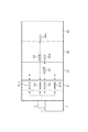
本発明の基板処理装置に係る実施の形態として、基板であるウエハWに処理液を供給して基板に付着したパーティクルや汚染物質を除去する液処理を行う液処理装置10の構成について以下に図面を参照しながら説明する。先ず本発明の概要について図1に基づいて簡単に説明すると、本発明の液処理装置10は、外部から複数枚のウエハWを収納したキャリアCの搬入出が行われるキャリア載置ブロック1と、ウエハWの受け渡し部を備えた受け渡しブロック2と、ウエハWに対して所定の液処理を行う他数個例えば3個の処理ブロック(第1の処理ブロック31、第2の処理ブロック32、第3の処理ブロック33)と、を備えている。これらは、キャリア載置ブロック1を前方側として、キャリア載置ブロック1、受け渡しブロック2、第1の処理ブロック31、第2の処理ブロック32、第3の処理ブロック33が前後方向に一列に配列され、互いに接続されている。
As an embodiment according to the substrate processing apparatus of the present invention, a configuration of a liquid processing apparatus 10 for performing a liquid processing for supplying particles to a wafer W as a substrate and removing particles and contaminants attached to the substrate will be described below. Will be described with reference to FIG. First, the outline of the present invention will be briefly described with reference to FIG. 1. A liquid processing apparatus 10 of the present invention includes a
前記受け渡しブロック2には、第1の処理ブロック31にウエハWを受け渡すための第1の受け渡しステージ(21a 21b)と、第2の処理ブロック32にウエハWを受け渡すための第2の受け渡しステージ22と、第3の処理ブロック33にウエハWを受け渡すための第3の受け渡しステージ23と、が夫々別個に設けられている。また第2の受け渡しステージ22と第2の処理ブロック32との間でウエハWの搬送を行うための専用の第1直接搬送機構である第1のシャトルアームA1と、第3の受け渡しステージ23と第3の処理ブロック33との間でウエハWを搬送するための専用の第2直接搬送機構である第2のシャトルアームA2と、が設けられている。
The
そして第2の受け渡しステージ22のウエハWは第1のシャトルアームA1により第2の処理ブロック32に直接搬送され、ここで所定の処理が行われた後、シャトルアームA1により第2の受け渡しステージ22に戻されるように構成されている。同様に第3の受け渡しステージ23のウエハWは第2のシャトルアームA2により第3の処理ブロック33に直接搬送され、ここで所定の処理が行われた後、シャトルアームA2により第3の受け渡し部23に戻されるように構成されている。このように本発明は、第2の処理ブロック32及び第3の処理ブロック33に対して、他の処理ブロックの搬送手段を介さずに、専用のシャトルアームA1,A2によりウエハWを直接搬送することを特徴としている。
Then, the wafer W on the
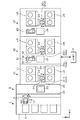
以下に各ブロックの構成について図2〜図7を参照しながら説明する。図2は液処理装置10の全体構成を示す横断平面図、図3は縦断側面図である。前記キャリア載置ブロック1は、例えば4個の基板搬送容器であるキャリアCが載置される容器載置部11を備えている。この容器載置部11上に載置されたキャリアCは、不図示の開閉機構により、各キャリアCの蓋及び各キャリアCとの接続面に設けられた開閉扉を開閉するように構成されている。また当該ブロック1は、容器載置部11上に載置されたキャリアCと受け渡しブロック2との間でのウエハWの受け渡しを行う受け渡し機構である搬入出アームBを備えている。
The configuration of each block will be described below with reference to FIGS. 2 is a cross-sectional plan view showing the overall configuration of the liquid processing apparatus 10, and FIG. 3 is a longitudinal side view. The
この搬入出アームBは、全てのキャリアCに対してアクセスすると共に、受け渡しブロック2に設けられた第1〜第3の受け渡しステージ(21a 21b)〜23に対してアクセスするために、ウエハを保持する保持アーム12が、駆動部により、例えば前後方向に進退自在、左右方向(図2中Y方向)に移動自在、回動自在及び昇降自在に構成されている。
This loading / unloading arm B holds all the carriers C and holds the wafer for accessing the first to third transfer stages (
前記受け渡しブロック2は、前後をキャリア載置ブロック1及び第1の処理ブロック31に挟まれた位置に設けられた筐体内の空間であり、例えばキャリア載置ブロック1と受け渡しブロック2との間に設けられた区画壁24と、受け渡しブロック2と第1ブロック31との間に設けられた区画壁25との間に、前記第1〜第3の受け渡しステージ(21a 21b)〜23を多段に備えた構造となっている。
The
例えば前記第1〜第3の受け渡しステージ(21a 21b)〜23は、共通の受け渡し棚26に多段に配設されている。この例では、第1の受け渡しステージ(21a 21b)は受け渡し棚26の上方側に設けられた上段第1の受け渡しステージ21aと、受け渡し棚26の下方側に設けられた下段第1の受け渡しステージ21bとからなり、第2の受け渡しステージ22及び第3の受け渡しステージ23は、受け渡し棚26の中央側に設けられている。前記第1の受け渡しステージ21a,21bは、夫々例えば8枚のウエハWが載置されるように構成され、第2及び第3の受け渡しステージ22,23は夫々例えば1枚のウエハWが載置されるように構成されている。前記区画壁24には開口部24aが形成され、区画壁25には開口部25aが形成されている。開口部24aは第1〜第3の受け渡しステージ(21a、21a)〜23に対応する位置に形成され、搬入出アームBにより、夫々受け渡しステージ(21a 21b)〜23にアクセスできるようになっている。開口部25aは第1〜第3の受け渡しステージ(21a 21b)〜23に対応する位置に形成され、第1及び第2のシャトルアームA1、A2、後述する第1の処理ブロック31に設けられたプロセスアームD11、D12より、それぞれ受け渡しステージ(21a 21b)〜23にアクセスできるようになっている。以上に説明したキャリア載置ブロック1、受け渡しブロック2は、本実施の形態の基板搬入ブロックを構成している。
For example, the first to third delivery stages (21 a 21 b) to 23 are arranged in multiple stages on a
続いて第1の処理ブロック31について説明する。この処理ブロック31は、図4に示すように、互いに積層された上段処理ブロック31a及び下段処理ブロック31bと、を備えている。上段処理ブロック31aには、前後方向に伸びるウエハWの直線搬送路である搬送路34aが設けられており、この搬送路34aを挟んで、キャリア載置ブロック1側から見て左右に各々2台の液処理ユニット4が互いに対向するように列設されている。また下段処理ブロック31bは上段処理ブロック31aと同様に構成されており、ウエハWの搬送路34bを挟んで、キャリア載置ブロック1側から見て左右に各々2台の液処理ユニット4が互いに対向するように列設されている。
Next, the
そして搬送路34aの左側に配置された上段処理ブロック31a及び下段処理ブロック31bの液処理ユニット4は筐体内に設けられると共に、例えば共通の棚ユニットU1に組み込まれている。また同様に搬送路34bの右側に配置された上段処理ブロック31a及び下段処理ブロック31bの液処理ユニット4は筐体内に設けられると共に、例えば共通の棚ユニットU2に組み込まれている。
The
図2〜図4に示すように各搬送路34a、34b内には、上段処理ブロック31aの基板搬送機構に相当するプロセスアームD11と、下段処理ブロック31bの基板搬送機構に相当するプロセスアームD12と、が互いに上下に設けられている。前記プロセスアームD11は、上段処理ブロック31aの4台の液処理ユニット4及び既述の上段第1の受け渡しステージ21aに対してウエハWの受け渡しを行うものである。また前記プロセスアームD12は、下段処理ブロック31bの4台の液処理ユニット4及び既述の下段第1の受け渡しステージ21bに対してウエハWの受け渡しを行うものである。なお図4では図示の便宜上、後述する第1の処理ブロック31、第2の処理ブロック32、第3の処理ブロック33を仕切る区画壁27,28については省略してある。
As shown in FIGS. 2 to 4, in each of the
各プロセスアームD11,D12は、棚ユニットU1における搬送路34a,34bに臨む壁面において、夫々上段側の液処理ユニット4の下部側と、下段側の液処理ユニット4の下部側に取り付けられている。これらプロセスアームD11,D12は同様に構成されているので、図4及び図5を用いてプロセスアームD12を例にして説明する。当該プロセスアームD12はウエハWの裏面側周縁を保持する保持アーム51が基台52に沿って進退自在に構成されると共に、この基台52が支持基体53上に回転機構54により鉛直軸まわりに回転自在に構成され、さらに前記支持基体53が上下方向に伸びるガイド55に沿って昇降自在、及び棚ユニットU1における搬送路34a、34bに臨む壁面に設けられたガイドレール56に沿って移動可能に構成されている。
The process arms D11 and D12 are respectively attached to the lower side of the upper
さらに上段処理ブロック31aと下段処理ブロック31bとの間には、前記第1及び第2のシャトルアームA1,A2の搬送領域が形成されている。前記第1のシャトルアームA1は第2の処理ブロック32にウエハWを搬送するための第1直接搬送機構に相当し、第2のシャトルアームA2は第3の処理ブロック33にウエハWを搬送するための第2直接搬送機構に相当するものであるので、これらシャトルアームA1,A2の詳細については、第2の処理ブロック32及び第3の処理ブロック33の説明の後に記載する。
Further, a transport area for the first and second shuttle arms A1 and A2 is formed between the
続いて第2の処理ブロック32及び第3の処理ブロック33について説明する。第1〜第3の処理ブロック31〜33はほぼ同様に構成されており、第2及び第3の処理ブロック32,33においても、第1の処理ブロック31と同様に上段処理ブロック32a,33aと、下段処理ブロック32b,33bと、上段プロセスアームD21,D31と、下段プロセスアームD22,32と、を備えている。また第2の処理ブロック32における棚ユニットU3,U4、第3の処理ブロック32における棚ユニットU5,U6は、夫々第1の処理ブロック31の棚ユニットU1,U2に相当するものである。
Next, the
第1の処理ブロック31と異なる部分について説明すると、先ず第2の処理ブロック32は、図2及び図3に示すように、第1の処理ブロック31と隣接する領域に受け渡し棚ユニットU7を備えている。この受け渡し棚ユニットU7には、第1のシャトルアームA1がアクセスする第2の受け渡しステージ35aと、上段プロセスアームD21によりウエハWの受け渡しが行われる上段ステージ35bと、下段プロセスアームD22によりウエハWの受け渡しが行われる下段ステージ35cとのステージ35a〜35cが多段に設けられている。またこれら受け渡し棚ユニットU7の各ステージの間でウエハWの受け渡しを行うために、上下搬送機構E1が設けられている。
The difference from the
この例においては、例えば前記第2の受け渡しステージ35a、上段ステージ35b及び下段ステージ35cは、例えば図6に示すように、ウエハWの裏面側を支持する複数本例えば3本の支持ピン37を備えている。そして前記上下搬送機構E1は、図2及び図6に示すように、例えばウエハWの裏面側中央部を保持する保持アーム57が基台58に沿って、前記ステージ側に向けて進退自在に設けられると共に、この基台58が上下方向に設けられたガイドレール59に沿って昇降自在に構成されている。この際保持アーム57が前進したときには、前記ステージの支持ピン37と干渉しない状態で所定の位置まで進入するように、支持ピン37の配置及び保持アーム57の形状が設定されている。なお図6では図示の便宜上、後述する第1の処理ブロック31、第2の処理ブロック32、第3の処理ブロック33を仕切る区画壁27,28及び棚ユニットU2,U4,U6については省略し、棚ユニットU7,U8についてはステージのみを描いている。
In this example, for example, the
また第3の処理ブロック33においても、図2及び図3に示すように、第2の処理ブロック32と隣接する領域に受け渡し棚ユニットU8を備えている。この受け渡し棚ユニットU8には、第2のシャトルアームA2がアクセスする第3の受け渡しステージ36aが設けられると共に、上段プロセスアームD31によりウエハWの受け渡しが行われる上段ステージ36bと、下段プロセスアームD32によりウエハWの受け渡しが行われる下段ステージ36cとのステージ36a〜36cが多段に設けられている。またこれら受け渡し棚ユニットU8の各ステージの間でウエハWの受け渡しを行うために、上下搬送機構E2が設けられている。前記第3の受け渡しステージ36a、上段ステージ36b及び下段ステージ36cや上下搬送機構E2の構成は、第2の処理ブロック32に設けられるものと同様である。
The
また、第1の処理ブロック31と第2の処理ブロック32の間に区画壁27を設け、第2の処理ブロック32と第3の処理ブロック33の間に区画壁28を設けている。区画壁27には、第1のシャトルアームA1が受け渡し棚ユニットU7の第2の受け渡しステージ35aとの間でウエハWの受け渡しを行うために、開口部27aが形成されている。さらに区画壁27には、第2のシャトルアームA2が通過できる開口部27bが形成されている。開口部27aと開口部27bの開口はお互いが独立しており雰囲気が隔離できている。
A
他方、区画壁28には、第2のシャトルアームA2が受け渡し棚ユニットU8の第3の受け渡しステージ36aとの間でウエハWの受け渡しを行うために、開口部28aが形成されている。このように各区画壁27、28により各処理ブロック31〜33を区画することにより、各処理ブロック31〜33間の雰囲気を隔離することができる。また、例えば一つの処理ブロック31〜33の修理を行う際に、他の処理ブロック31〜33に影響を与えない。この結果、修理等に際して液処理装置10全体を停止することなく処理の実行を継続することが可能である。
On the other hand, an
続いて第1及び第2のシャトルアームA1,A2について説明する。先ず第1のシャトルアームA1は、例えば図5及び図6に示すように、第1の処理ブロック31の下部側の液処理ユニット4と上部側の液処理ユニット4との間において、プロセスアームD11,D12と干渉しない位置に設けられている。具体的には例えば棚ユニットU1における搬送路34bに臨む壁面において、下部側の液処理ユニット4の直ぐ上部側に取り付けられている。そしてウエハWの裏面側周縁を保持する保持アーム61が基台62に沿って進退自在に構成されると共に、この基台62が支持基体63上に回転機構64により鉛直軸まわりに回転自在に構成され、さらに前記支持基体63が棚ユニットU1の壁面に設けられたガイドレール65に沿って移動自在に構成されている。そして第1のシャトルアームA1は、受け渡し棚ユニットU7の第2の受け渡しステージ35aとの間で、開口部27aを介してウエハWの受け渡しを行う。
Next, the first and second shuttle arms A1 and A2 will be described. First, for example, as shown in FIGS. 5 and 6, the first shuttle arm A <b> 1 is formed between the lower
また第2のシャトルアームA2は、例えば図5及び図6に示すように、第1及び第2の処理ブロック31,32に跨って移動するように設けられ、これらブロック31,32の下部側の液処理ユニット4と上部側の液処理ユニット4との間において、プロセスアームD11,D12、D21,D22と干渉しない位置に設けられている。この例では例えばシャトルアームA2のガイドレール65は棚ユニットU1及び棚ユニットU3に跨って設けられており、当該シャトルアームA2のガイドレール65は、シャトルアームA1のガイドレール65が取り付けられた位置の上部側であって、上部側の液処理ユニット4の下に取り付けられている。このシャトルアームA2は、ガイドレール65が棚ユニットU1及び棚ユニットU3の壁面に跨って設けられる以外は上述のシャトルアームA1と同様に構成されている。
The second shuttle arm A2 is provided so as to move across the first and second processing blocks 31, 32 as shown in FIGS. 5 and 6, for example. Between the
このように第2のシャトルアームA2は受け渡しブロック2の第3の受け渡しステージ23と第3の処理ブロック31の第3の受け渡しステージ36aとの間でウエハWを直接搬送するために、第1の処理ブロック31及び第2の処理ブロック32を通過する。このため第1の処理ブロック31と第2の処理ブロック32との間の区画壁27に形成された開口部27aは、第2のシャトルアームA2が通過できる大きさに形成されている。第2のシャトルアームA2は、受け渡し棚ユニットU8の第3の受け渡しステージ36aとの間で、開口部28aを介してウエハWの受け渡しを行う。さらに第2の処理ブロック32の受け渡し棚ユニットU7にも第2のシャトルアームA2の通過領域が形成されている。
As described above, the second shuttle arm A2 directly transfers the wafer W between the
これら第1及び第2のシャトルアームA1,A2は、受け渡しステージとの間でウエハWの受け渡しを行うときに保持アーム61が多少昇降するが、支持基体63が昇降する構成ではないので、図5に記載されるように、上段プロセスアームD11,D21と下段プロセスアームD12,D22との間の領域をこれらプロセスアームD11,D12,D21,D22と干渉することなく、図3中X方向に移動自在に構成される。
In these first and second shuttle arms A1 and A2, the holding
さらに、本実施形態においては、第2のシャトルアームA2の上部に第2のシャトルアームA2のガイドレール65に沿ってシャトルアーム用隔壁111が設けられている。また、第2のシャトルアームA2のガイドレール65に沿って、その下部にシャトルアーム用隔壁112が設けられている。さらに第1のシャトルアームA1のガイドレール65に沿って、その下部にシャトルアーム用隔壁113が設けられている。これにより、第1のシャトルアームA1と第1のシャトルアームA1のガイドレール65は、シャトルアーム用隔壁112とシャトルアーム用隔壁113により形成され、処理ブロック31aと処理ブロック31bから隔離された空間に設けられることになる。また、第2のシャトルアームA2と第2のシャトルアームA2のガイドレール65は、シャトルアーム用隔壁111とシャトルアーム用隔壁112により形成され、処理ブロック31aと処理ブロック31b、処理ブロック32aと処理ブロック32bから隔離された空間に設けられることになる。
Furthermore, in this embodiment, a shuttle
このようにシャトルアーム用隔壁111〜113により、各シャトルアームA1、A2が各処理ブロック31a、31b、32a、32bから隔離されることにより、各処理ブロック31a、31b、32a、32b間の雰囲気も隔離できる。このため、例えば一つの処理ブロック31a、31b、32a、32bの修理を行う際に、隔離された空間内でウエハWの搬送が可能であり、且つ、各処理ブロック31a、31b、32a、32b同士も互いに隔離されているので、運転中の他の処理ブロック31a、31b、32a、32bに影響を与えない。この結果、液処理装置10全体を停止することなく処理の実行を継続することが可能である。
Thus, the
次に図7を参照しながら前記液処理ユニット4の構成について説明する。液処理ユニット4は、ウエハWに対して枚葉処理を行う処理ユニットであり、ウエハWに対する液処理、リンス洗浄、振切乾燥の各処理が実行される密閉された処理空間を形成するアウターチャンバー41と、このアウターチャンバー41内に設けられ、ウエハWをほぼ水平に保持した状態で回転させるウエハ保持機構43と、ウエハ保持機構43に保持されたウエハWの上面側に液を供給するノズルアーム44と、ウエハ保持機構43を取り囲むようにアウターチャンバー41内に設けられ、回転するウエハWから周囲に飛散した液を受けるためのインナーカップ42と、を備えている。
Next, the configuration of the
アウターチャンバー41は、互いに隣り合う他の液処理ユニット4とは区画された筐体内に設けられており、この筐体内には不図示のウエハ搬入口を介して対応するプロセスアームD11〜D32によりウエハWが搬入出されるように構成されている。図7中46はアウターチャンバー41の底面に溜まったDIWなどの排水を排出するための排水ライン、47はアウターチャンバー41内の雰囲気を排気するための排気ラインである。またウエハ保持機構43の内部には液供給路48が形成されており、回転するウエハWの下面に当該液供給路48を介して液を供給することができるようになっている。
The
ノズルアーム44は、先端部に液供給用のノズルを備えており、不図示の駆動機構によってウエハ保持機構43に保持されたウエハW中央側の上方位置と、例えばアウターチャンバー41の外部に設けられた待機位置との間で前記ノズルを移動するように構成されている。インナーカップ42は、ウエハ保持機構43に保持されたウエハWを取り囲む処理位置と、この処理位置の下方へ退避した退避位置との間を昇降し、回転するウエハW表面に供給された各種の液を受け止めて、インナーカップ42の底面に設けられた排液ライン45を介してこれらの液を液処理ユニット4外へと排出する役割を果たすものである。
The
次に各液処理ユニット4への液の供給機構について説明すると、ノズルアーム44に設けられたノズルは上面側供給ライン71に接続されており、この上面側供給ライン71はIPA供給ライン72と液供給中間ライン73とに分岐している。IPA供給ライン72は、マスフローコントローラ72aを介してIPA供給部72bに接続されており、このIPA供給部72bは高い揮発性を利用してウエハWを乾燥させるためのIPA(イソプロピルアルコール)をウエハWの上面側に供給する役割を果たす。
Next, the mechanism of supplying the liquid to each
前記液供給中間ライン73は、切替弁73aを介して3系統の液供給ライン74、75、76に分岐され、前記液供給ライン74は液処理後のウエハWに残存する希フッ酸水溶液(以下、DHF(Diluted HydroFluoric acid)液という)やSC1液(アンモニアと過酸化水素水の混合液)を除去するリンス液であるDIW(DeIonized Water)を供給するためのDIW供給部74aに接続されている。また液供給ライン75は、ウエハW表面のパーティクルや有機性の汚染物質を除去する薬液であるSC1液を供給するSC1供給部75aに接続され、また液供給ライン76は、ウエハW表面の自然酸化膜を除去する酸性薬液であるDHF液を供給するDHF供給部76aに接続されている。
The liquid supply
また液供給中間ライン73は、ウエハWの下面に液を供給する液供給路48に対して下面側供給ライン77を介して接続されている。図7中、78a、78bは、各々ノズルアーム44側、ウエハ保持機構43側への液供給量を調整するマスフローコントローラである。
The liquid supply
図2に示すように液処理装置10には制御部8が接続されている。制御部8は例えばCPUと記憶部とを備えたコンピュータからなり、記憶部には当該液処理装置10の作用、各液処理ブロック31〜33の液処理ユニット4にウエハWを搬入して液処理を行った後、液処理後のウエハWをキャリアCに格納するまでの動作に係わる制御についてのステップ(命令)群が組まれたプログラムがレシピ毎に記録されている。前記プログラムは、例えばハードディスク、コンパクトディスク、マグネットオプティカルディスク、メモリーカード等の記憶媒体に格納され、そこからコンピュータにインストールされる。
As shown in FIG. 2, a controller 8 is connected to the liquid processing apparatus 10. The control unit 8 is composed of, for example, a computer having a CPU and a storage unit. The operation of the liquid processing apparatus 10 and the wafer W are loaded into the
例えば前記レシピは、あるロットのウエハWに対して、どの処理ブロック31〜33にてどのような液処理を行うかを示したものである。例えば処理ブロック31〜33にて同じ液処理を行う場合や、処理ブロック31〜処理ブロック33にて異なる液処理を行う場合の、夫々の場合についてレシピが作成されている。ここで薬液が同じであっても、液処理温度が異なる場合や、液処理時間が異なる場合には、異なる液処理となる。 For example, the recipe indicates what liquid processing is performed in which processing blocks 31 to 33 with respect to a wafer W of a certain lot. For example, a recipe is created for each case where the same liquid processing is performed in the processing blocks 31 to 33 or different liquid processing is performed in the processing blocks 31 to 33. Here, even if the chemical solution is the same, if the liquid processing temperature is different or the liquid processing time is different, different liquid processing is performed.
続いて本発明の液処理装置10の作用について、先ず第1の処理ブロック31〜第3の処理ブロック33にて同じ液処理を行う場合を例にして説明する。外部からキャリア載置ブロックS1に搬入されたキャリアC内のウエハWは、搬入出アームBにより受け渡しブロック2の受け渡しステージに受け渡される。この際、各処理ブロック31〜33には、夫々8台の液処理ユニットが設けられているので、例えば先ず第1の処理ブロック31に8枚のウエハWを搬送してから、次いで第2の処理ブロック32に8枚のウエハWを搬送し、続いて第3の処理ブロック33に8枚のウエハWを搬送するように、同じロットのウエハWを第1〜第3の処理ブロック31〜33に振り分けて搬送する。
Next, the operation of the liquid processing apparatus 10 according to the present invention will be described first by taking as an example the case where the same liquid processing is performed in the
この際、第1の処理ブロック31にウエハWを搬送するときには、上段処理ブロック31a及び下段処理ブロック31bに夫々4台の液処理ユニット4が設けられているので、キャリアC内のウエハWは搬入出アームBにより、受け渡しブロック2における上段第1の受け渡しステージ21aに4枚のウエハWが搬送され、下段第1の受け渡しステージ21bに4枚のウエハWを搬送される。そして第1の処理ブロック31では、上段プロセスアームD11が上段第1の受け渡しステージ21aからウエハWを受け取って、所定の液処理ユニット4に搬送し、ここで所定の液処理を行う。液処理後のウエハWは上段プロセスアームD11により上段第1の受け渡しステージ21aに戻される。
At this time, when the wafer W is transferred to the
また下段処理ブロック31bでは、下段プロセスアームD12が下段第1の受け渡しステージ21bからウエハWを受け取って、所定の液処理ユニット4に搬送し、ここで所定の液処理を行う。液処理後のウエハWは下段プロセスアームD12により下段第1の受け渡しステージ21bに戻される。そして第1の受け渡しステージ21a,21bに載置された液処理後のウエハWは、搬入出アームBにより元のキャリアに戻される。
In the
また第2の処理ブロック32にウエハWを搬送するときには、キャリアC内のウエハWは搬入出アームBにより、受け渡しブロック2の第2の受け渡しステージ22に受け渡される。そしてこの受け渡しステージ22上のウエハWは第1のシャトルアームA1により受け取られて、第2の処理ブロック32の第2の受け渡しステージ35aに直接搬送される。当該第2の受け渡しステージ35aのウエハWは上下搬送機構E1により上段ステージ35b及び下段ステージ35cに順番に受け渡される。そして上段ステージ35bのウエハWは上段プロセスアームD21により上段処理ブロック32aの液処理ユニット4に搬送され、所定の液処理が行われる。液処理終了後のウエハWは上段プロセスアームD21により上段ステージ35bに搬送され、上下搬送機構E1により第2の受け渡しステージ35aに受け渡される。
When the wafer W is transferred to the
一方下段ステージ35cのウエハWは下段プロセスアームD22により下段処理ブロック32bの液処理ユニット4に搬送される。液処理終了後のウエハWは下段プロセスアームD22により下段ステージ35cに搬送され、上下搬送機構E1により第2の受け渡しステージ35aに受け渡される。第2の受け渡しステージ35a上の液処理後のウエハWは第1のシャトルアームA1により受け渡しブロック2の第2の受け渡しステージ22に搬送され、搬入出アームBにより元のキャリアC内に戻される。
On the other hand, the wafer W on the
同様に第3の処理ブロック33にウエハWを搬送するときには、キャリアC内のウエハWは搬入出アームBにより、受け渡しブロック2の第3の受け渡しステージ23に受け渡される。そしてこの受け渡しステージ23上のウエハWは第2のシャトルアームA2により受け取られて、第3の処理ブロック33の第3の受け渡しステージ36aに直接搬送される。当該第3の受け渡しステージ36aのウエハWは上下搬送機構E2により上段ステージ36b及び下段ステージ36cに順番に受け渡される。そして上段ステージ36bのウエハWは上段プロセスアームD31により上段処理ブロック33aの液処理ユニット4に搬送され、所定の液処理が行われる。液処理終了後のウエハWは上段プロセスアームD31により上段ステージ36bに搬送され、上下搬送機構E2により第3の受け渡しステージ36aに受け渡される。
Similarly, when the wafer W is transferred to the
一方下段ステージ36cのウエハWは下段プロセスアームD32により下段処理ブロック33bの液処理ユニット4に搬送される。液処理終了後のウエハWは下段プロセスアームD32により下段ステージ36cに搬送され、上下搬送機構E2により第3の受け渡しステージ36aに受け渡される。第3の受け渡しステージ36a上の液処理後のウエハWは第2のシャトルアームA2により受け渡しブロック2の第2の受け渡しステージ22に直接搬送され、搬入出アームBにより元のキャリアC内に戻される。
On the other hand, the wafer W on the
以上において、既述のように第1の処理ブロック31の全ての液処理ユニットにウエハWを搬送してから、第2の処理ブロック32の全ての液処理ユニットにウエハWを搬送し、次いで第3の処理ブロック33にウエハWが搬送するようにしてもよいし、第2の処理ブロック32と第3の処理ブロック33とに順番にウエハWを搬送するようにしてもよい。ウエハWの搬送順序については、液処理ユニットにて行われる処理時間や、ウエハWの処理枚数等に応じて適宜決定される。
In the above, after transferring the wafer W to all the liquid processing units of the
ここで各々の液処理ユニット4にて行われる液処理の一例について、第1の処理ブロック31の上段処理ブロック31aに設けられた液処理ユニット4を例にして説明する。当該上段処理ブロック31aでは、上段ステージ35bからウエハWを受け取ったプロセスアームD11は液処理ユニット4の一つに進入して、当該ウエハWをウエハ保持機構43に受け渡す。次いでノズルアーム44をウエハW中央側の上方位置まで移動させ、インナーカップ42を処理位置まで上昇させる。そしてウエハ保持機構43によりウエハWを回転させながら、ノズル及びウエハ保持機構43側の薬液供給路48よりウエハWの上下面両側にSC1液を供給する。これによりウエハWに薬液の液膜が形成されてアルカリ性薬液洗浄が行われる。
Here, an example of the liquid processing performed in each
アルカリ性薬液洗浄が終了すると、インナーカップ42を退避位置に移動し、またノズル及びウエハ保持機構43の薬液供給路48へDIWを供給することによりウエハW表面のSC1液を除去するリンス洗浄が実行される。リンス洗浄を終えたら振切乾燥を実行し、しかる後、再びインナーカップ42を処理位置まで上昇させ、ウエハWを回転させながら、ノズル及びウエハ保持機構23の薬液供給路48より、ウエハWの上下面にDHF液を供給する。これによりこれらの面にDHF液の液膜が形成され、酸性薬液洗浄が行われる。そして所定時間の経過後、インナーカップ42を退避位置に下降させ、薬液の供給系統を純水に切り替えて再びリンス洗浄を行う。
When the alkaline chemical cleaning is completed, the
続いてインナーカップ42を処理位置まで上昇させ、液処理ユニット4の上面にIPAを供給しながらウエハWを回転させ、IPAの揮発性を利用したIPA乾燥を実行する。これによりウエハW表面に残存するリンス後の純水が完全に除去される。しかる後、インナーカップ42を退避位置まで退避させ、不図示の搬入出口を開き、液処理ユニット4内にプロセスアームD11を進入させて処理後のウエハWを搬出し、このウエハWを上段ステージ35bに受け渡す。
Subsequently, the
上述の実施の形態によれば、第1の処理ブロック31と第2の処理ブロック32と第3の処理ブロック33とを備え、第2の処理ブロック32と第3の処理ブロック33には、夫々第1のシャトルアームA1、第2のシャトルアームA2により基板搬入ブロックから搬入出アームBを介して受け渡されたウエハWを直接搬送している。このため基板搬入ブロックのウエハWを速やかに第2及び第3の処理ブロック32,33に搬送することができるので、スループットの向上を図ることができる。
According to the above-described embodiment, the
つまりシャトルアームA1、A2は受け渡しブロック2と夫々の処理ブロック32,32との間でのウエハWの搬送を行う専用の搬送機構であるので、他の処理ブロックのプロセスアームDによる搬送と干渉することなく、独立してウエハWの搬送を行っている。このため受け渡しブロック2から第2及び第3の処理ブロック32,33に対して高速でウエハWの受け渡しを行うことができるので、既述のようにスループットを向上させることができる。
That is, since the shuttle arms A1 and A2 are dedicated transfer mechanisms for transferring the wafer W between the
またこのように第1の処理ブロック31〜第3の処理ブロック33に対して独立してウエハWを搬送することができるので、1つの処理ブロックに不具合が発生したとしても、他の処理ブロックにおいては処理の継続が可能となる。例えば第1の処理ブロック31に不具合が発生すれば、第2の処理ブロック32及び第3の処理ブロック33にウエハWを搬送して処理を行い、第2の処理ブロック32に不具合が発生すれば、第1の処理ブロック31及び第3の処理ブロック33にウエハWを搬送して処理を行うことができる。これらは例えば制御部8において、処理ブロックに不具合が発生したら、不具合が発生した処理ブロックのプロセスアームの駆動を停止すると共に、受け渡しブロック2では不具合が発生した処理ブロックの受け渡しステージにはウエハを搬送しないように、搬入出アームBによるウエハWの受け渡しを制御することにより行われる。
In addition, since the wafer W can be transferred independently from the
このように一つの処理ブロックにおいて不具合が発生したとしても、他の処理ブロックにおいては処理を継続して行うことができるため、装置全体を停止することなく、装置の稼働率の低下を抑えることができる。 Thus, even if a problem occurs in one processing block, the processing can be continued in other processing blocks, so that it is possible to suppress a reduction in the operating rate of the apparatus without stopping the entire apparatus. it can.
さらにまた、第1の処理ブロック31〜第3の処理ブロック33に対して独立してウエハWを搬送することができるので、ウエハWの処理枚数に合わせて、稼働させる処理ブロックを選択することができる。例えば処理枚数が少ないプロセスでは、第1の処理ブロック31のみ又は第1の処理ブロック31及び第2の処理ブロック32のみを稼働させることが可能となる。この場合には、例えば制御部8において、第1の処理ブロック31のみを使用するレシピ、第1及び第2の処理ブロック31,32のみを使用するレシピを作成しておき、これを選択することにより、搬入出アームBやプロセスアームD11,12,21,22、上下搬送機構E1、対応する液処理ユニットの駆動が制御される。この場合、稼働させない処理ブロックが発生するが、プロセスアームDを無駄に移動させる必要がないため、稼働コストの低減を図ることができる。
Furthermore, since the wafer W can be transferred independently to the
さらにまた上述の実施の形態では、第2の処理ブロック32及び第3の処理ブロック33は同じ構成であり、このように同じ構成の処理ブロックを増設することにより、液処理ユニットの個数をさらに増加することができる。このように新たな処理ブロックを増設するときには、例えば第2のシャトルアームA2の上方側であって、第1〜第3の処理ブロック31〜33における上段プロセスアームと干渉しない位置に、受け渡しブロック2と新たな処理ブロックとの間でウエハWを直接搬送するための専用のシャトルアームが設けられる。
Furthermore, in the above-described embodiment, the
また本発明の液処理装置10では、既述のように第1の処理ブロック31〜第3の処理ブロック33にて異なる液処理を行うようにしてもよい。この場合には、既述のように、レシピには、ロットのウエハをどの処理ブロックに搬送し、当該処理ブロックにてどのような液処理を行うかが記載されているので、ロットのウエハを対応する処理ブロックに搬送する。
In the liquid processing apparatus 10 of the present invention, different liquid processing may be performed in the
第1の処理ブロック31〜第3の処理ブロック33にて夫々異なる液処理を行う場合には、例えばキャリアC1のウエハW1については第1の処理ブロック31にて液処理を行い、キャリアC2のウエハW2については第2の処理ブロック32にて液処理を行い、キャリアC3のウエハW3については第3の処理ブロック33にて液処理を行うように、夫々のキャリアC1〜C3のウエハWが対応する処理ブロック31〜33に搬送される。
When different liquid processing is performed in the
この際、先ずキャリアC1内の全てのウエハW1を順次第1の処理ブロック31に受け渡して、所定の液処理を行ない、液処理後のウエハW1をキャリアC1内に戻してから、キャリアC2(C3)内の全てのウエハW2(W3)を順次第2の処理ブロック32(第3の処理ブロック33)に受け渡して、所定の液処理を行ない、液処理後のウエハW2(W3)をキャリアC2(C3)内に戻すようにしてもよい。また、先ずキャリアC1内のウエハW1を第1の処理ブロック31内の全ての液処理ユニット4に受け渡してから、キャリアC2(C3)内のウエハW2を順次第2の処理ブロック32(第3の処理ブロック33)に受け渡すようにして、全ての処理ブロック31〜33にて並行して異なる液処理を行うようにしてもよい。この際、第2の処理ブロック32の液処理ユニットを全て満たしてから、第3の処理ブロック33にウエハWを搬送するようにしてもよいし、第2の処理ブロック32と第3の処理ブロック33とに順番にウエハWを搬送するようにしてもよい。ウエハWの搬送順序については、液処理ユニットにて行われる処理時間や、ウエハWの処理枚数等に応じて適宜決定される。
At this time, first, all the wafers W1 in the carrier C1 are sequentially transferred to the
このような実施の形態では、第1の処理ブロック31〜第3の処理ブロック33にて別々の処理を行うことができるので、処理枚数が少ないロットは1つの処理ブロックを用いて処理を行うなど、プロセスに応じて使用する処理ブロックを選択でき、装置の稼働率を向上させることができる。
In such an embodiment, since separate processing can be performed in the
以上において、本発明では、図8及び図9に示すように、第1の処理ブロックも第2及び第3の処理ブロックと同様の構成としてもよい。この例では、キャリア載置ブロック1の後段には第1の処理ブロック30が接続されている。そして第1の処理ブロック30には、キャリア載置ブロック1の搬入出アームBがアクセスできる領域に、受け渡しステージが多段に配列された受け渡し棚ユニットU0が設けられ、ここに前記搬入出アームBとの間でウエハWの受け渡しを行う第1の受け渡しステージ20が設けられている。
In the above, in the present invention, as shown in FIGS. 8 and 9, the first processing block may have the same configuration as the second and third processing blocks. In this example, the
この受け渡し棚ユニットU0の上段側には、上段プロセスアームD11にウエハWの受け渡しを行うために上段ステージ30aが設けられ、その下段側には、下段プロセスアームD12にウエハWの受け渡しを行うために下段ステージ30bが設けられている。また受け渡し棚ユニットU0の第1の受け渡しステージ20と上段ステージ30a、下段ステージ30bとの間は、上下搬送機構E0によりウエハWの受け渡しが行われるようになっている。この例においてはキャリア載置ブロック1が基板搬入ブロックを構成している。また搬入出アームBとの間でウエハWの受け渡しを行う第2の受け渡しステージ22と、第3の受け渡しステージ23とは、第1の処理ブロック30の受け渡し棚ユニットU0に設けられている。その他の構成については上述の実施の形態と同様であり、同じ構成部分については同じ符号を付している。
An
当該実施の形態においては、第1の処理ブロック31にウエハを受け渡す場合には、外部からキャリア載置ブロックS1に搬入されたキャリアC内のウエハWは、搬入出アームBにより第1の処理ブロック30の第1の受け渡しステージ20に受け渡される。当該受け渡しステージ20のウエハWは上下搬送機構E0により上段ステージ30a及び下段ステージ30bに順番に受け渡される。そして上段ステージ30aのウエハWは上段プロセスアームD11により上段処理ブロック31aの液処理ユニット4に搬送され、下段ステージ30bのウエハWは下段プロセスアームD12により下段処理ブロック31bの液処理ユニット4に搬送され、夫々所定の液処理が行われる。液処理終了後のウエハWは夫々のプロセスアームD11,D12により上段ステージ30a又は下段ステージ30bに搬送され、上下搬送機構E0により第1の受け渡しステージ20に受け渡され、搬入出アームBによりキャリアCに戻される。
In this embodiment, when the wafer is delivered to the
また第2の処理ブロック32(第3の処理ブロック33)にウエハWを搬送するときには、キャリアC内のウエハWは搬入出アームBにより、第1の処理ブロック30の第2の受け渡しステージ22(第3の受け渡しステージ23)に受け渡される。そしてこの受け渡しステージ22(23)上のウエハWは第1のシャトルアームA1(第2のシャトルアームA2)により受け取られて、第2の処理ブロック32の第2の受け渡しステージ35a(第3の処理ブロック33の第3の受け渡しステージ36a)に直接搬送される。以降は、上述の実施の形態と同様である。
When the wafer W is transferred to the second processing block 32 (third processing block 33), the wafer W in the carrier C is transferred by the loading / unloading arm B to the second delivery stage 22 ( Delivered to the third delivery stage 23). The wafer W on the delivery stage 22 (23) is received by the first shuttle arm A1 (second shuttle arm A2), and the
このような構成では、搬入出アームBの上下方向の移動距離が短くて済み、第1の処理ブロック30〜第3の処理ブロック33まで、液処理ユニット、受け渡し棚ユニット、プロセスアームを同じ構成とすることができるので、設計や製造が容易であるという利点がある。
In such a configuration, the vertical movement distance of the loading / unloading arm B is short, and the liquid processing unit, the delivery shelf unit, and the process arm have the same configuration from the
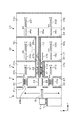
さらに本発明では、図10及び図11に示すように、第1の処理ブロック〜第3の処理ブロックを上下方向に積層して設けるようにしてもよい。この図において、91はキャリア載置ブロック、92は受け渡しブロックであり、これらにより基板搬入ブロックが構成されている。また図中90は容器載置部をなすキャリア載置部である。受け渡しブロック92の後段には、第1の処理ブロック93と、第2の処理ブロック94と、第3の処理ブロック95とが、下からこの順番で積層して設けられている。
Furthermore, in the present invention, as shown in FIGS. 10 and 11, the first processing block to the third processing block may be stacked in the vertical direction. In this figure, 91 is a carrier mounting block, 92 is a delivery block, and these constitute a substrate carry-in block. In the figure,
前記受け渡しブロック92には、受け渡し機構をなす搬入出アームBから第1の処理ブロック93にウエハWの受け渡すための第1の受け渡しステージ96と、搬入出アームBから第2の処理ブロック94にウエハWの受け渡すための第2の受け渡しステージ97aと、搬入出アームBから第3の処理ブロック95にウエハWの受け渡すための第3の受け渡しステージ98aと、がキャリアCの配列方向(図10中Y方向)に並ぶように設けられている。この例では、搬入出アームBは進退自在、鉛直軸まわりに回転自在及び左右方向(図10中Y方向)に移動自在に構成されている。
The
また受け渡しブロック92における第2の受け渡しステージ97aの上方側であって、第2の処理ブロック94に対応する位置には、上方側受け渡しステージ97bが設けられている。さらにこの第2の受け渡しステージ97aと上方側受け渡しステージ97bとの間でウエハWを直接搬送するための第1直接搬送機構F1が設けられている。
An
さらにまた受け渡しブロック92における第3の受け渡しステージ98aの上方側であって、第3の処理ブロック95に対応する位置には、上方側受け渡しステージ98bが設けられている。そしてこの第3の受け渡しステージ98aと上方側受け渡しステージ98bとの間でウエハWを直接搬送するための第2直接搬送機構F2が設けられている。これら第1、第2直接搬送機構F1,F2は、ウエハWを保持する保持アーム99が進退自在、かつ上下方向に移動自在に構成されている。
Furthermore, an
一方、第1の処理ブロック93、第2の処理ブロック94、第3の処理ブロック95には、各々ウエハWに対して処理を行うための複数の処理ユニット100と、これら処理ユニット100に対してウエハWの受け渡しを行うための基板搬送機構D1〜D3が設けられている。そして第1〜第3の処理ブロック93〜95では、基板搬送機構D1〜D3により、対応する受け渡しステージ96、上段側受け渡しステージ97b,98bとの間でウエハWの受け渡しを行うように構成されている。
On the other hand, each of the
当該実施の形態では、第1〜第3処理ブロック93〜95は上下方向に配置されているが、「基板搬入ブロック側から順に配置される」とは、基板搬入ブロックの受け渡し機構(搬入出アームB)がアクセスする領域から順番に配置されていることを意味する。当該実施の形態では、搬入出アームBは上下方向に移動しないため、当該アームBがアクセスする領域は、第1の処理ブロック93のプロセスアームD1との間でウエハWの受け渡しを行うことができる領域であり、ここから上方側に順番に第2の処理ブロック94、第3の処理ブロック95が配置されている。
In the present embodiment, the first to third processing blocks 93 to 95 are arranged in the vertical direction, but “arranged in order from the substrate carry-in block side” means that the substrate carry-in block delivery mechanism (load-in / out arm) B) means that they are arranged in order from the area to be accessed. In this embodiment, since the loading / unloading arm B does not move in the vertical direction, the area accessed by the arm B can transfer the wafer W to and from the process arm D1 of the
このような構成では、キャリアC内のウエハWは搬入出アームBにより第1〜第3の受け渡しステージ96,97a,98aに順次受け渡され、第1の受け渡しステージ96上のウエハWは第1の処理ブロック93の基板搬送機構D1により受け取られて、第1の処理ブロック93内に受け渡される。また第2の受け渡しステージ97a上のウエハWは、第1直接搬送機構F1により上方側受け渡しステージ97bに搬送され、次いで第2の処理ブロック94の基板搬送機構D2により受け取られて、第2の処理ブロック94内に受け渡される。さらに第3の受け渡しステージ98a上のウエハWは、第2直接搬送機構F2により上方側受け渡しステージ98bに搬送され、次いで第3の処理ブロック95の基板搬送機構D3により受け取られて、第3の処理ブロック95内に受け渡される。
In such a configuration, the wafer W in the carrier C is sequentially transferred to the first to third transfer stages 96, 97a, and 98a by the loading / unloading arm B, and the wafer W on the
このような実施の形態においても、第1、第2直接搬送機構F1,F2により受け渡しブロック2から直接第2の処理ブロック94、第3の処理ブロック95へウエハWが搬送されるので、各処理ブロックへのウエハWの受け渡しをスムースに行うことができ、スループットの向上を図ることができる。また各処理ブロック93〜95へ独立してウエハWを搬送することができるので、一つの処理ブロックにて不具合が発生したときであっても、他の処理ブロックでは処理を継続でき、装置の稼働率の低下を抑えることができる。また当該実施の形態では、処理ブロックを多段に積層しているので、液処理ユニットを増加したとしても、装置のフットプリントの増大を抑えることができるという効果も得られる。
Also in such an embodiment, the wafer W is directly transferred from the
以上において、上述の構成では処理ユニットとしては同じ構成の液処理ユニットを組み込むようにしたが、1つの処理ブロックに、ウエハWの表面側を洗浄する表面洗浄ユニットと、ウエハWの裏面側を洗浄する裏面洗浄ユニットと、ウエハWの反転ユニット等の異なる構成の処理ユニットを組み込むようにしてもよい。但し第1〜第3の処理ブロックに組み込まれる処理ユニットの種類や数、レイアウトと同じである。 In the above configuration, the liquid processing unit having the same configuration as the processing unit is incorporated in the above configuration, but the front surface cleaning unit for cleaning the front surface side of the wafer W and the back surface side of the wafer W are cleaned in one processing block. A processing unit having a different configuration such as a back surface cleaning unit and a wafer W reversing unit may be incorporated. However, this is the same as the type, number, and layout of the processing units incorporated in the first to third processing blocks.
また上述の実施の形態では直接搬送機構の保持アームが1枚であるが、複数枚の保持アームを設ける構成とし、複数のウエハWを同時に一方の受け渡しステージから受け取り、他方の受け渡しステージに受け渡すようにしてもよい。
さらに、キャリアCからウエハWを搬入出するための搬入出アームBも複数の保持アーム12を設ける構成としてもよい。
In the above-described embodiment, there is one holding arm of the direct transfer mechanism. However, a plurality of holding arms are provided, and a plurality of wafers W are simultaneously received from one transfer stage and transferred to the other transfer stage. You may do it.
Further, the loading / unloading arm B for loading / unloading the wafer W from / from the carrier C may be provided with a plurality of holding arms 12.
さらに上述の実施の形態では渡し棚ユニットU7、U8の上段ステージ35b、36bや下段ステージ35c、36c並びに第2、第3の受け渡しステージ35a、36a及び、受け渡しブロック2の受け渡しステージ22、23にウエハWを1枚のみ載置する構成として記載したが、ここに複数枚のウエハWを多段に載置するようにしてもよいし、上下搬送機構がアクセスする領域に、ウエハWのバッファを設けるようにしてもよい。
Furthermore, in the above-described embodiment, wafers are provided on the
さらにまた基板搬入ブロックの搬入出アームBとシャトルアームA1,A2(第1、第2直接搬送機構F1,F2)との間のウエハWの受け渡しは、受け渡しステージを設けずに、保持アーム同士で直接受け渡しを行うようにしてもよい。 Furthermore, the transfer of the wafer W between the loading / unloading arm B of the substrate loading block and the shuttle arms A1 and A2 (first and second direct transfer mechanisms F1 and F2) is performed between the holding arms without providing a transfer stage. Direct delivery may be performed.
また流体を使う処理は上述の液処理に限られるものではなく、例えばウエハWにHMDS(ヘキサメチルジシラザン)などの蒸気を供給してウエハWの表面を疎水化する処理装置にも適用することができる。 In addition, the processing using fluid is not limited to the above-described liquid processing, and for example, it may be applied to a processing apparatus that supplies a vapor such as HMDS (hexamethyldisilazane) to the wafer W to make the surface of the wafer W hydrophobic. Can do.
A1,A2 シャトルアーム
B 搬入出アーム
C キャリア
D1,D2,D3 プロセスアーム
D11,D21,D31 上段プロセスアーム
D21,D22,D32 下段プロセスアーム
W ウエハ
1 キャリア載置ブロック
2 受け渡しブロック
31〜33、93〜95 処理ブロック
4 液処理ユニット
A1, A2 Shuttle arm B Loading / unloading arm C Carrier D1, D2, D3 Process arm D11, D21, D31 Upper process arm D21, D22, D32 Lower process
Claims (10)
基板に対して処理を行うための複数の処理ユニットと、これら処理ユニットに対して基板の受け渡しを行うための基板搬送機構と、を備えた処理ブロックであって、前記基板搬入ブロック側から順に互いに横方向に配置されている第1の処理ブロック、第2の処理ブロック及び第3の処理ブロックと、
前記受け渡し機構により基板搬送容器から受け渡された基板が載置され、前記第1の処理ブロックに基板を受け渡すための第1の受け渡しステージと、
前記第1の受け渡しステージとは別に設けられ、前記受け渡し機構により基板搬送容器から受け渡された基板が載置され、前記第2の処理ブロックに基板を受け渡すための第2の受け渡しステージと、
前記第1の受け渡しステージ及び第2の受け渡しステージとは別に設けられ、前記受け渡し機構により基板搬送容器から受け渡された基板が載置され、前記第3の処理ブロックに基板を受け渡すための第3の受け渡しステージと、
前記第1の処理ブロックが配置されている領域を通過して、前記第2の受け渡しステージと第2の処理ブロックとの間で基板を専用に直接搬送するための第1直接搬送機構と、
前記第1直接搬送機構とは別に設けられ、前記第1の処理ブロック及び第2の処理ブロックが配置されている領域を通過して、前記第2の処理ブロックに基板を受け渡すことなく、前記第3の受け渡しステージと第3の処理ブロックとの間で基板を専用に直接搬送するための第2直接搬送機構と、を備えたことを特徴とする基板処理装置。 A substrate loading block including a container placing portion on which a substrate carrying container storing a substrate is placed; and a delivery mechanism for delivering the substrate to the substrate carrying container placed on the container placing portion;
A processing block comprising a plurality of processing units for processing a substrate and a substrate transport mechanism for transferring the substrate to these processing units, in order from the substrate loading block side. A first processing block, a second processing block, and a third processing block arranged in a horizontal direction;
A first delivery stage for placing the substrate delivered from the substrate transport container by the delivery mechanism and delivering the substrate to the first processing block;
A second delivery stage provided separately from the first delivery stage, on which the substrate delivered from the substrate transport container by the delivery mechanism is placed, and for delivering the substrate to the second processing block;
The first transfer stage is provided separately from the first transfer stage and the second transfer stage, and a substrate transferred from the substrate transfer container by the transfer mechanism is placed thereon, and a first transfer unit for transferring the substrate to the third processing block. 3 delivery stages,
A first direct transport mechanism for directly transporting the substrate directly between the second transfer stage and the second processing block through an area where the first processing block is disposed;
Wherein the first direct transfer mechanism is provided separately, and passes through the area where the first processing block and the second processing block is located without passing the substrate to the second processing block, A substrate processing apparatus, comprising: a second direct transfer mechanism for directly transferring a substrate directly between the third delivery stage and the third processing block.
前記第3の処理ブロックは、前記第2直接搬送機構との間で基板の受け渡しが行われる受け渡しステージを備えることを特徴とする請求項1記載の基板処理装置。 The second processing block includes a transfer stage for transferring a substrate to and from the first direct transfer mechanism,
The substrate processing apparatus according to claim 1, wherein the third processing block includes a transfer stage for transferring the substrate to and from the second direct transfer mechanism.
これら上段処理ブロック及び下段処理ブロックの各々は、各々基板に対して処理を行うための複数の処理ユニットと、これら処理ユニットに対して基板の受け渡しを行うための基板搬送機構と、を備え、
前記第2の処理ブロック及び第3の処理ブロックの各々は、前記上段処理ブロックの基板搬送機構により基板の受け渡しが行われる上段ステージと、前記下段処理ブロックの基板搬送機構により基板の受け渡しが行われる下段ステージと、前記第1直接搬送機構または、第2直接搬送機構により搬送された基板を前記上段ステージあるいは下段ステージに受け渡す上下搬送機構と、を備えることを特徴とする請求項1記載の基板処理装置。 Each of the first processing block, the second processing block, and the third processing block includes an upper processing block and a lower processing block stacked on each other,
Each of the upper processing block and the lower processing block includes a plurality of processing units for processing each of the substrates, and a substrate transport mechanism for transferring the substrates to these processing units,
In each of the second processing block and the third processing block, the substrate is transferred by the substrate transfer mechanism of the upper processing block and the substrate transfer mechanism of the lower processing block. 2. The substrate according to claim 1, further comprising: a lower stage; and a vertical transport mechanism that delivers the substrate transported by the first direct transport mechanism or the second direct transport mechanism to the upper stage or the lower stage. Processing equipment.
これら上段処理ブロック及び下段処理ブロックの各々は、各々基板に対して処理を行うための複数の処理ユニットと、これら処理ユニットに対して基板の受け渡しを行うための基板搬送機構と、を備え、
前記第2の処理ブロック及び第3の処理ブロックの各々は、前記上段処理ブロックの基板搬送機構により基板の受け渡しが行われる上段ステージと、前記下段処理ブロックの基板搬送機構により基板の受け渡しが行われる下段ステージと、前記第1直接搬送機構または、前記第2直接搬送機構により搬送された基板を前記上段ステージあるいは下段ステージに受け渡す上下搬送機構と、前記第1直接搬送機構または、前記第2直接搬送機構により搬送された基板と前記上下搬送機構との間で基板の受け渡しを行うための受け渡しステージと、を備えることを特徴とする請求項1記載の基板処理装置。 Each of the first processing block, the second processing block, and the third processing block includes an upper processing block and a lower processing block stacked on each other,
Each of the upper processing block and the lower processing block includes a plurality of processing units for processing each of the substrates, and a substrate transport mechanism for transferring the substrates to these processing units,
In each of the second processing block and the third processing block, the substrate is transferred by the substrate transfer mechanism of the upper processing block and the substrate transfer mechanism of the lower processing block. A lower stage, a vertical transport mechanism for transferring a substrate transported by the first direct transport mechanism or the second direct transport mechanism to the upper stage or the lower stage, the first direct transport mechanism, or the second direct The substrate processing apparatus according to claim 1, further comprising a transfer stage for transferring the substrate between the substrate transferred by the transfer mechanism and the vertical transfer mechanism.
前記受け渡しブロックは、前記第1の受け渡しステージと、前記第2の受け渡しステージと、前記第3の受け渡しステージと、を備えることを特徴とする請求項1ないし4のいずれか一つに記載の基板処理装置。 A delivery block between the substrate loading block and the first processing block;
5. The substrate according to claim 1, wherein the delivery block includes the first delivery stage, the second delivery stage, and the third delivery stage. 6. Processing equipment.
Priority Applications (5)
| Application Number | Priority Date | Filing Date | Title |
|---|---|---|---|
| JP2010180921A JP5736687B2 (en) | 2009-10-06 | 2010-08-12 | Substrate processing equipment |
| CN201010501399.3A CN102034727B (en) | 2009-10-06 | 2010-09-29 | Substrate processing apparatus |
| US12/895,576 US8443513B2 (en) | 2009-10-06 | 2010-09-30 | Substrate processing apparatus |
| KR1020100095308A KR101590648B1 (en) | 2009-10-06 | 2010-09-30 | Substrate processing apparatus |
| TW99133727A TWI467686B (en) | 2009-10-06 | 2010-10-04 | Substrate processing device |
Applications Claiming Priority (3)
| Application Number | Priority Date | Filing Date | Title |
|---|---|---|---|
| JP2009232769 | 2009-10-06 | ||
| JP2009232769 | 2009-10-06 | ||
| JP2010180921A JP5736687B2 (en) | 2009-10-06 | 2010-08-12 | Substrate processing equipment |
Publications (3)
| Publication Number | Publication Date |
|---|---|
| JP2011100970A JP2011100970A (en) | 2011-05-19 |
| JP2011100970A5 JP2011100970A5 (en) | 2013-03-14 |
| JP5736687B2 true JP5736687B2 (en) | 2015-06-17 |
Family
ID=43822051
Family Applications (1)
| Application Number | Title | Priority Date | Filing Date |
|---|---|---|---|
| JP2010180921A Active JP5736687B2 (en) | 2009-10-06 | 2010-08-12 | Substrate processing equipment |
Country Status (5)
| Country | Link |
|---|---|
| US (1) | US8443513B2 (en) |
| JP (1) | JP5736687B2 (en) |
| KR (1) | KR101590648B1 (en) |
| CN (1) | CN102034727B (en) |
| TW (1) | TWI467686B (en) |
Families Citing this family (20)
| Publication number | Priority date | Publication date | Assignee | Title |
|---|---|---|---|---|
| JP5006122B2 (en) | 2007-06-29 | 2012-08-22 | 株式会社Sokudo | Substrate processing equipment |
| JP5160204B2 (en) * | 2007-11-30 | 2013-03-13 | 株式会社Sokudo | Substrate processing equipment |
| JP5128918B2 (en) | 2007-11-30 | 2013-01-23 | 株式会社Sokudo | Substrate processing equipment |
| JP5179170B2 (en) | 2007-12-28 | 2013-04-10 | 株式会社Sokudo | Substrate processing equipment |
| JP5001828B2 (en) | 2007-12-28 | 2012-08-15 | 株式会社Sokudo | Substrate processing equipment |
| US8882431B2 (en) * | 2008-10-07 | 2014-11-11 | Kawasaki Jukogyo Kabushiki Kaisha | Substrate transfer robot and substrate transfer system |
| WO2012098871A1 (en) * | 2011-01-20 | 2012-07-26 | 東京エレクトロン株式会社 | Vacuum processing apparatus |
| US9153464B2 (en) * | 2011-05-31 | 2015-10-06 | Semes Co., Ltd. | Substrate processing apparatus and substrate processing method |
| JP2013033963A (en) * | 2011-07-29 | 2013-02-14 | Semes Co Ltd | Substrate processing apparatus and substrate processing method |
| US8985929B2 (en) * | 2011-09-22 | 2015-03-24 | Tokyo Electron Limited | Substrate processing apparatus, substrate processing method and storage medium |
| US9048271B2 (en) | 2011-09-29 | 2015-06-02 | Asm International N.V. | Modular semiconductor processing system |
| JP6058999B2 (en) * | 2012-12-11 | 2017-01-11 | 株式会社Screenセミコンダクターソリューションズ | Substrate processing apparatus and substrate processing method |
| KR101527901B1 (en) * | 2013-10-10 | 2015-06-10 | 피에스케이 주식회사 | Apparatus for treating substrate and method for transfering substrate |
| US10236196B2 (en) * | 2013-11-14 | 2019-03-19 | Tokyo Electron Limited | Substrate processing system |
| JP5977728B2 (en) * | 2013-11-14 | 2016-08-24 | 東京エレクトロン株式会社 | Substrate processing system |
| JP5977729B2 (en) * | 2013-11-14 | 2016-08-24 | 東京エレクトロン株式会社 | Substrate processing system |
| DK178352B1 (en) * | 2015-02-27 | 2016-01-04 | Intelligent Systems As | Transport and storage system for servicing a number of treatment and care areas in a hospital, as well as methods for operating them. |
| JP6292155B2 (en) * | 2015-03-19 | 2018-03-14 | 東京エレクトロン株式会社 | Substrate processing apparatus, substrate processing method, and storage medium |
| KR102478317B1 (en) * | 2015-04-08 | 2022-12-16 | 도쿄엘렉트론가부시키가이샤 | Substrate processing system |
| KR102168381B1 (en) * | 2018-06-07 | 2020-10-21 | 세메스 주식회사 | Substrate treating method and substrate treating apparatus |
Family Cites Families (10)
| Publication number | Priority date | Publication date | Assignee | Title |
|---|---|---|---|---|
| JP3442669B2 (en) * | 1998-10-20 | 2003-09-02 | 東京エレクトロン株式会社 | Substrate processing equipment |
| JP3462426B2 (en) * | 1999-05-24 | 2003-11-05 | 東京エレクトロン株式会社 | Substrate processing equipment |
| JP4381909B2 (en) * | 2004-07-06 | 2009-12-09 | 大日本スクリーン製造株式会社 | Substrate processing apparatus and substrate processing method |
| JP4685584B2 (en) * | 2005-03-11 | 2011-05-18 | 東京エレクトロン株式会社 | Coating and developing equipment |
| JP4816217B2 (en) * | 2006-04-14 | 2011-11-16 | 東京エレクトロン株式会社 | Coating, developing device, coating, developing method and storage medium |
| JP4767783B2 (en) | 2006-07-26 | 2011-09-07 | 東京エレクトロン株式会社 | Liquid processing equipment |
| JP4687682B2 (en) * | 2007-03-30 | 2011-05-25 | 東京エレクトロン株式会社 | Coating and developing apparatus and method, and storage medium |
| TW200919117A (en) * | 2007-08-28 | 2009-05-01 | Tokyo Electron Ltd | Coating-developing apparatus, coating-developing method and storage medium |
| JP5362232B2 (en) * | 2008-02-13 | 2013-12-11 | 大日本スクリーン製造株式会社 | Substrate processing equipment |
| JP5050018B2 (en) * | 2009-08-24 | 2012-10-17 | 東京エレクトロン株式会社 | Coating and developing apparatus and coating and developing method |
-
2010
- 2010-08-12 JP JP2010180921A patent/JP5736687B2/en active Active
- 2010-09-29 CN CN201010501399.3A patent/CN102034727B/en active Active
- 2010-09-30 US US12/895,576 patent/US8443513B2/en active Active
- 2010-09-30 KR KR1020100095308A patent/KR101590648B1/en active IP Right Grant
- 2010-10-04 TW TW99133727A patent/TWI467686B/en active
Also Published As
| Publication number | Publication date |
|---|---|
| US20110078898A1 (en) | 2011-04-07 |
| TWI467686B (en) | 2015-01-01 |
| JP2011100970A (en) | 2011-05-19 |
| TW201133682A (en) | 2011-10-01 |
| CN102034727B (en) | 2014-07-09 |
| CN102034727A (en) | 2011-04-27 |
| KR101590648B1 (en) | 2016-02-01 |
| US8443513B2 (en) | 2013-05-21 |
| KR20110037865A (en) | 2011-04-13 |
Similar Documents
| Publication | Publication Date | Title |
|---|---|---|
| JP5736687B2 (en) | Substrate processing equipment | |
| JP5505384B2 (en) | Substrate processing apparatus, substrate processing method, and storage medium | |
| US8235061B2 (en) | Substrate processing apparatus and substrate processing method | |
| JP5445006B2 (en) | Substrate processing apparatus, substrate processing method, and storage medium | |
| JP5381592B2 (en) | Substrate processing equipment | |
| KR101596064B1 (en) | Substrate processing apparatus | |
| TWI483331B (en) | Processing apparatus and operating method therefor | |
| KR101489314B1 (en) | Substrate processing apparatus, substrate processing method and storage medium | |
| KR101356228B1 (en) | Substrate treatment apparatus | |
| JP7113949B2 (en) | Substrate processing equipment | |
| KR20150013050A (en) | Liquid processing apparatus | |
| KR102319168B1 (en) | Coating and developing apparatus, and coating and developing method | |
| JP6224359B2 (en) | Schedule creation method and schedule creation program for substrate processing apparatus | |
| JP2022057798A (en) | Substrate processing system and substrate conveyance method | |
| KR100598917B1 (en) | Apparatus and method for cleaning of single substrate type | |
| KR102346804B1 (en) | Substrate processing apparatus and substrate processing method | |
| CN214042007U (en) | Coating and developing device | |
| JP6675955B2 (en) | Substrate processing equipment | |
| JP2007251026A (en) | Substrate processing apparatus, substrate processing method, and substrate processing program | |
| JP2024047292A (en) | Substrate Processing Equipment | |
| JP2021190441A (en) | Substrate processing apparatus and substrate processing method | |
| KR20050049910A (en) | Wafer transfer apparatus and wafer cleaning system using this apparatus |
Legal Events
| Date | Code | Title | Description |
|---|---|---|---|
| A621 | Written request for application examination |
Free format text: JAPANESE INTERMEDIATE CODE: A621 Effective date: 20130123 |
|
| A521 | Request for written amendment filed |
Free format text: JAPANESE INTERMEDIATE CODE: A523 Effective date: 20130128 |
|
| A977 | Report on retrieval |
Free format text: JAPANESE INTERMEDIATE CODE: A971007 Effective date: 20131122 |
|
| A131 | Notification of reasons for refusal |
Free format text: JAPANESE INTERMEDIATE CODE: A131 Effective date: 20131224 |
|
| A521 | Request for written amendment filed |
Free format text: JAPANESE INTERMEDIATE CODE: A523 Effective date: 20140224 |
|
| A131 | Notification of reasons for refusal |
Free format text: JAPANESE INTERMEDIATE CODE: A131 Effective date: 20140325 |
|
| A521 | Request for written amendment filed |
Free format text: JAPANESE INTERMEDIATE CODE: A523 Effective date: 20140526 |
|
| A131 | Notification of reasons for refusal |
Free format text: JAPANESE INTERMEDIATE CODE: A131 Effective date: 20150106 |
|
| A521 | Request for written amendment filed |
Free format text: JAPANESE INTERMEDIATE CODE: A523 Effective date: 20150224 |
|
| TRDD | Decision of grant or rejection written | ||
| A01 | Written decision to grant a patent or to grant a registration (utility model) |
Free format text: JAPANESE INTERMEDIATE CODE: A01 Effective date: 20150324 |
|
| A61 | First payment of annual fees (during grant procedure) |
Free format text: JAPANESE INTERMEDIATE CODE: A61 Effective date: 20150406 |
|
| R150 | Certificate of patent or registration of utility model |
Ref document number: 5736687 Country of ref document: JP Free format text: JAPANESE INTERMEDIATE CODE: R150 |
|
| R250 | Receipt of annual fees |
Free format text: JAPANESE INTERMEDIATE CODE: R250 |
|
| R250 | Receipt of annual fees |
Free format text: JAPANESE INTERMEDIATE CODE: R250 |
|
| R250 | Receipt of annual fees |
Free format text: JAPANESE INTERMEDIATE CODE: R250 |
|
| R250 | Receipt of annual fees |
Free format text: JAPANESE INTERMEDIATE CODE: R250 |