JP5736218B2 - Light source device - Google Patents
Light source device Download PDFInfo
- Publication number
- JP5736218B2 JP5736218B2 JP2011081409A JP2011081409A JP5736218B2 JP 5736218 B2 JP5736218 B2 JP 5736218B2 JP 2011081409 A JP2011081409 A JP 2011081409A JP 2011081409 A JP2011081409 A JP 2011081409A JP 5736218 B2 JP5736218 B2 JP 5736218B2
- Authority
- JP
- Japan
- Prior art keywords
- light
- light source
- guide plate
- light emitting
- light guide
- Prior art date
- Legal status (The legal status is an assumption and is not a legal conclusion. Google has not performed a legal analysis and makes no representation as to the accuracy of the status listed.)
- Active
Links
Images


Classifications
-
- G—PHYSICS
- G02—OPTICS
- G02B—OPTICAL ELEMENTS, SYSTEMS OR APPARATUS
- G02B6/00—Light guides; Structural details of arrangements comprising light guides and other optical elements, e.g. couplings
- G02B6/0001—Light guides; Structural details of arrangements comprising light guides and other optical elements, e.g. couplings specially adapted for lighting devices or systems
- G02B6/0011—Light guides; Structural details of arrangements comprising light guides and other optical elements, e.g. couplings specially adapted for lighting devices or systems the light guides being planar or of plate-like form
- G02B6/0013—Means for improving the coupling-in of light from the light source into the light guide
- G02B6/0023—Means for improving the coupling-in of light from the light source into the light guide provided by one optical element, or plurality thereof, placed between the light guide and the light source, or around the light source
-
- G—PHYSICS
- G02—OPTICS
- G02B—OPTICAL ELEMENTS, SYSTEMS OR APPARATUS
- G02B6/00—Light guides; Structural details of arrangements comprising light guides and other optical elements, e.g. couplings
- G02B6/0001—Light guides; Structural details of arrangements comprising light guides and other optical elements, e.g. couplings specially adapted for lighting devices or systems
- G02B6/0011—Light guides; Structural details of arrangements comprising light guides and other optical elements, e.g. couplings specially adapted for lighting devices or systems the light guides being planar or of plate-like form
- G02B6/0075—Arrangements of multiple light guides
- G02B6/0076—Stacked arrangements of multiple light guides of the same or different cross-sectional area
-
- G—PHYSICS
- G02—OPTICS
- G02B—OPTICAL ELEMENTS, SYSTEMS OR APPARATUS
- G02B6/00—Light guides; Structural details of arrangements comprising light guides and other optical elements, e.g. couplings
- G02B6/0001—Light guides; Structural details of arrangements comprising light guides and other optical elements, e.g. couplings specially adapted for lighting devices or systems
- G02B6/0011—Light guides; Structural details of arrangements comprising light guides and other optical elements, e.g. couplings specially adapted for lighting devices or systems the light guides being planar or of plate-like form
- G02B6/0033—Means for improving the coupling-out of light from the light guide
- G02B6/0035—Means for improving the coupling-out of light from the light guide provided on the surface of the light guide or in the bulk of it
-
- G—PHYSICS
- G02—OPTICS
- G02B—OPTICAL ELEMENTS, SYSTEMS OR APPARATUS
- G02B6/00—Light guides; Structural details of arrangements comprising light guides and other optical elements, e.g. couplings
- G02B6/0001—Light guides; Structural details of arrangements comprising light guides and other optical elements, e.g. couplings specially adapted for lighting devices or systems
- G02B6/0011—Light guides; Structural details of arrangements comprising light guides and other optical elements, e.g. couplings specially adapted for lighting devices or systems the light guides being planar or of plate-like form
- G02B6/0066—Light guides; Structural details of arrangements comprising light guides and other optical elements, e.g. couplings specially adapted for lighting devices or systems the light guides being planar or of plate-like form characterised by the light source being coupled to the light guide
- G02B6/0073—Light emitting diode [LED]
Description
本発明は、光源装置に関するものである。 The present invention relates to a light source device.
一般的に、室内または室外の照明灯として電球や蛍光灯が多く使用されている。 Generally, bulbs and fluorescent lamps are often used as indoor or outdoor illumination lamps.
ところが、このような電球や蛍光灯は寿命が短くて頻繁に交換しなけらばならないという問題がある。また、従来の蛍光灯は、その使用期間の経過による劣化により照度が漸次に落ちる現象が過度に発生するという問題がある。 However, such bulbs and fluorescent lamps have a short life and have a problem that they must be replaced frequently. In addition, the conventional fluorescent lamp has a problem that the phenomenon that the illuminance gradually decreases due to deterioration due to the passage of the period of use thereof excessively occurs.
このような問題を解決するために、優れた制御性、速い応答速度、高い電気光変換効率、長い寿命、低い消費電力及び高い輝度の特性及び感性照明を具現することができるLEDを使用する照明器具が開発されつつある。 In order to solve such problems, lighting using LEDs that can realize excellent controllability, fast response speed, high electro-optical conversion efficiency, long life, low power consumption and high luminance characteristics and sensitive lighting Instruments are being developed.
発光素子(LED)照明は次世代照明であって、半導体素子を応用した照明であり、紫外線より長波長の光を用いるので人体に無害である。 Light-emitting element (LED) illumination is next-generation illumination that uses semiconductor elements and is harmless to the human body because it uses light having a longer wavelength than ultraviolet light.
従って、現在、LEDを適用した多くの照明器具が開発されつつあるが、照明の根源となる光の特性、例えば、演色指数特性や多様な色を具現するにおいて、多くの部品が所要されている実情である。 Therefore, many lighting fixtures using LEDs are currently being developed, but many parts are required to realize the characteristics of light that is the source of lighting, such as color rendering index characteristics and various colors. It is a fact.
実施例による光源装置は、導光板と、前記導光板の下側に配置された反射板と、前記導光板の側部に光学的に結合された光源部と、前記導光板と光源部との間に配置された光励起フィルムと、を含み、前記光励起フィルムは、区画された2つ以上の領域を含み、前記2つ以上の領域のうち少なくとも1つの領域に含まれた第1蛍光物質は、残りの領域に属する第2蛍光物質と異なる。 A light source device according to an embodiment includes a light guide plate, a reflection plate disposed below the light guide plate, a light source unit optically coupled to a side portion of the light guide plate, and the light guide plate and the light source unit. A photoexcitation film disposed between the photoexcitation film, the photoexcitation film including two or more partitioned areas, and the first fluorescent material included in at least one of the two or more areas is Different from the second fluorescent material belonging to the remaining region.
実施例による他の光源装置は、導光板と、前記導光板の下側に配置された反射板と、前記導光板に光学的に結合された複数の発光素子と、前記導光板と光源部との間に配置された光励起フィルムと、を含み、前記複数の発光素子は2000K〜3000K範囲の相関色温度を発散するウォームホワイト発光素子(Warm white LED)と、5500K〜6500K範囲の相関色温度を発散するクールホワイト発光素子(Cool white LED)と、を含み、前記ウォームホワイト発光素子とクールホワイト発光素子は前記光励起フィルムの長さ方向に配置される。 Another light source device according to the embodiment includes a light guide plate, a reflective plate disposed below the light guide plate, a plurality of light emitting elements optically coupled to the light guide plate, the light guide plate, and a light source unit. A plurality of light emitting devices, wherein the plurality of light emitting devices emit a correlated color temperature ranging from 2000K to 3000K and a correlated color temperature ranging from 5500K to 6500K. A cool white light emitting element (Cool white LED) that diverges, and the warm white light emitting element and the cool white light emitting element are disposed in a length direction of the photoexcitation film.
実施例によるまた他の光源装置は、導光板と、前記導光板の側部に光学的に結合された光源部と、前記光源部から放出した光の波長帯を変化させ、前記導光板に光を出射させる光励起フィルムと、を含み、前記光励起フィルムには、前記光励起フィルムの長さ方向に第1蛍光物質と、前記第1蛍光物質と異なる第2蛍光物質が区画されてランダムに配列される。 Another light source device according to the embodiment includes a light guide plate, a light source unit optically coupled to a side portion of the light guide plate, a wavelength band of light emitted from the light source unit, and light on the light guide plate. A first fluorescent material and a second fluorescent material different from the first fluorescent material are partitioned and randomly arranged in the length direction of the photoexcited film. .
実施例による光源装置は、高演色性を具現し、物体の色が歪むことを防止することができる。
実施例による光源装置は、多様な色を混合し、感性照明を演出することができる。
実施例による光源装置は、重さ及び厚さを減らし、照明装置のスリム化を具現することができる。
実施例による光源装置は、部品の数を減らし、製造コストを減らすことができる。
The light source device according to the embodiment realizes high color rendering and can prevent the color of the object from being distorted.
The light source device according to the embodiment can produce a sensitive illumination by mixing various colors.
The light source device according to the embodiment can reduce the weight and thickness, and can realize slimming of the lighting device.
The light source device according to the embodiment can reduce the number of parts and the manufacturing cost.
以下、添付された図面を参照して実施例を詳しく説明する。 Hereinafter, embodiments will be described in detail with reference to the accompanying drawings.
図1は、本発明の実施例による光源装置を示す斜視図であり、図2は、本発明の実施例による光源装置の光源部を示す図であり、図3は、本発明の実施例による光源部の発光素子の配列構造を示す図であり、図4は、本発明の実施例による光励起フィルムの構造を示す図である。 FIG. 1 is a perspective view illustrating a light source device according to an embodiment of the present invention, FIG. 2 is a diagram illustrating a light source unit of the light source device according to the embodiment of the present invention, and FIG. 3 is according to the embodiment of the present invention. FIG. 4 is a diagram illustrating an arrangement structure of light emitting elements of a light source unit, and FIG. 4 is a diagram illustrating a structure of a photoexcitation film according to an example of the present invention.
まず、図1を参照すると、第1実施例による光源装置100は導光板110、反射板130、光源部150、光励起フィルム170及び拡散フィルム190を含む。
First, referring to FIG. 1, the
導光板110は点光源を面光源に変換させるもので、内部に入射された光が外部に出射できるように一面にパターン111が形成される。パターン111は光を拡散または散乱させて外部に出射させる役割をする。このような導光板110は透明樹脂で製造され、シルクスクリーン印刷方式等で印刷され得る。
The
導光板110の上側には、拡散フィルム190が配置され得る。拡散フィルム190は、導光板110の内部に入射された光が外部に均等に出射されるようにする役割をする。
A
反射板130は導光板110の下側に配置され、導光板110の内部に入射された光が導光板の後方に出射されることを防止する。
The
光源部150は導光板110の側部に配置され、光源部150は光を出射できる装置であればいずれも可能であり、本発明の実施例においては発光素子を使用する。このような光源部150は導光部110と光学的に結合され、光源部150から発生した光が導光部110の内部に入射される。
The
光源部150は図2に示すように、印刷回路基板151と印刷回路基板151上に配置された複数の発光素子152とを含み、複数の発光素子152は印刷回路基板の長さ方向に一列に配列される。複数の発光素子152は青色発光素子であってもよいが、可能であれば演色指数(Color Rendering Index:CRI)の高い白色発光素子を使用する。白色発光素子は、青色発光のチップ上部に黄色蛍光体を含む合成樹脂がモールディングされてホワイトを具現する発光素子であってもよい。この際、合成樹脂はシリコン樹脂(Silicon resin)またはエポキシ樹脂(Epoxy resin)であってもよい。また、白色発光素子は演色指数を高めるために、緑色蛍光体や赤色蛍光体をさらに含むことができる。即ち、青色発光のチップ上部には、主に黄色蛍光体を含む合成樹脂がモールディングされ、緑色及び赤色蛍光体の順に合成樹脂に含まれ得る。蛍光体はガーネット(Garnet)系、シリケート(Silicate)系、ナイトライド(Nitride)系、オキシナイトライド(Oxynitride)系のうち少なくとも一つが含まれ得る。この際、ガーネット系はYAG(Y3Al5O12:Ce3+)やTAG(Tb3Al5O12:Ce3+)を使用し、シリケート系は(Sr、Ba、Mg、Ca)2SiO4:Eu2+、ナイトライド系はCaAlSiN3:Eu2+、オキシナイトライド系はSi6−xAlxOxN8−x:Eu2+を使用することができる。
As shown in FIG. 2, the
一方、合成樹脂に含まれた蛍光体の割合が黄色、緑色、赤色の順である場合、黄色はガーネット系、緑色はシリケート系、赤色はナイトライド系を含むことができ、黄色はシリケート系、緑色はシリケート系、赤色はナイトライド系を含むことができ、黄色はガーネット系、緑色はオキシナイトライド系、赤色はナイトライド系を含むことができ、黄色はオキシナイトライド系、緑色はオキシナイトライド系、赤色はナイトライド系を含むことができる。 On the other hand, when the proportion of the phosphor contained in the synthetic resin is in the order of yellow, green, and red, yellow can include garnet, green can include silicate, red can include nitride, yellow can be silicate, Green can contain silicate, red can contain nitride, yellow can contain garnet, green can contain oxynitride, red can contain nitride, yellow is oxynitride, green is oxynitrite Ride type and red color can include nitride type.
図3のように、光源部150に含まれた複数の発光素子152は、ウォームホワイト発光素子152−aと、クールホワイト発光素子152−bとで構成され、印刷回路基板151上に交互に配列される。従って、面光源で光が出射されるとき、全体光出射面で均等に混合された光が出射され得る。
As shown in FIG. 3, the plurality of
勿論、図面に示されてはいないが、光出射面で局部的にまたはランダムに特定の色を具現することを所望する場合、ウォームホワイト発光素子及びクールホワイト発光素子は、印刷回路基板上に局部的または順序に関係なくランダムに配列され得る。 Of course, although not shown in the drawings, the warm white light emitting element and the cool white light emitting element are locally formed on the printed circuit board when it is desired to implement a specific color locally or randomly on the light emitting surface. It can be randomly arranged regardless of target or order.
一方、ウォームホワイト発光素子152−aは2000K〜3000Kの範囲内の相関色温度を発散する発光素子であって、暖かい色を帯び、クールホワイト発光素子152−bは5500K〜6500K範囲内の相関色温度を発散する発光素子であって、冷たい色を帯びる。このようなウォームホワイト発光素子152−aとクールホワイト発光素子152−bはレッド(Red)、グリーン(Green)、ブルー(Blue)発光素子の組み合わせなしにそれ自体で白色光を発散させる素子である。即ち、ウォームホワイト発光素子152-aとクールホワイト発光素子152−bは青色のチップ上部に該当する相関色温度に変換して光を発散することができるようにする蛍光体が含まれた合成樹脂がモールディングされ、相関色温度をホワイトに具現するようになる。 On the other hand, the warm white light emitting element 152-a emits a correlated color temperature in the range of 2000K to 3000K, has a warm color, and the cool white light emitting element 152-b has a correlated color in the range of 5500K to 6500K. A light emitting device that emits temperature and has a cold color. The warm white light emitting element 152-a and the cool white light emitting element 152-b are elements that emit white light by themselves without a combination of red, green, and blue light emitting elements. . That is, the warm white light emitting element 152-a and the cool white light emitting element 152-b are converted into a correlated color temperature corresponding to the upper part of the blue chip, and a synthetic resin including a phosphor that can emit light. Is molded, and the correlated color temperature is realized in white.
このように、ウォームホワイト発光素子152−aとクールホワイト発光素子152−bがそれぞれ相関色温度を発散して混合された光の白色光を発散させることができるので、自然太陽光に近いことを表す演色指数が高くなる。従って、実際、物体の色が歪むことを防止することができ、ユーザの目の疲れを減少させる。 In this way, the warm white light emitting element 152-a and the cool white light emitting element 152-b can diverge the correlated color temperature and diverge the white light of the mixed light, so that it is close to natural sunlight. The color rendering index is high. Therefore, in fact, it is possible to prevent the color of the object from being distorted and to reduce the eyestrain of the user.
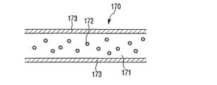
光励起フィルム170は導光部110と光源部150との間に配置され、内部に多様な蛍光物質を含む。このような光励起フィルム170は光源部150から出射された光の波長の一部を変換させて光の色を変換する。
The
図4に示すように、光励起フィルム170は透明樹脂171の内部に蛍光物質172が含有される。蛍光物質はガーネット系、シリケート系、ナイトライド系、オキシナイトライド系のうち少なくとも一つが含まれ得る。この際、ガーネット系はYAG(Y3Al5O12:Ce3+)やTAG(Tb3Al5O12:Ce3+)を使用し、シリケート系は(Sr、Ba、Mg、Ca)2SiO4:Eu2+、ナイトライド系はCaAlSiN3:Eu2+、オキシナイトライド系はSi6−xAlxOxN8−x:Eu2+を使用することができる。
As shown in FIG. 4, the
透明樹脂の外側には透明な保護フィルム173が積層される。透明な樹脂は、主にシリコン樹脂が用いられ、その他、透明性を有する材料であれば、いずれも使用可能である。
A transparent
図示してはいないが、透明樹脂の内部には硬化剤や添加剤が含まれてもよく、硬化剤は透明樹脂を硬化させ、添加剤は蛍光物質を透明樹脂の内部で均等に分散させる。また、透明樹脂の内部には拡散材が含まれてもよく、拡散材は光源の屈折を向上させて蛍光物質の励起率を高くする。 Although not shown, a curing agent or an additive may be included in the transparent resin, the curing agent cures the transparent resin, and the additive uniformly disperses the fluorescent substance in the transparent resin. In addition, a diffusing material may be included inside the transparent resin, and the diffusing material improves the refraction of the light source and increases the excitation rate of the fluorescent material.
透明樹脂の外側に配置された保護フィルム173は蛍光物質の耐湿性及び耐熱性を確保するためのものであり、このような保護フィルム173は光透過度に優れた無色透明な合成樹脂を使用するが、特に限定されるのではなく、例えば、ポリエチレンテレフタレート(Polyethylene terephthalate:PET)、ポリエチレンナフタレート(Polyethylene naphthalate)、アクリル樹脂、ポリカーボネート(Polycarbonate)、ポリスチレン(Polystyrene)などがある。
The
図5は、本発明による実施例であり、光励起フィルムに含まれた蛍光物質の配列構造及び光励起フィルムと光源部との配列構造を示す。 FIG. 5 is an example according to the present invention, and shows an arrangement structure of fluorescent substances contained in a photoexcitation film and an arrangement structure of a photoexcitation film and a light source part.
図示されているように、光励起フィルム170は、透明な樹脂171の内部に第1蛍光物質172aと、第1蛍光物質172aと異なる第2蛍光物質172bを含む第1領域と第2領域を含み、第1領域と第2領域に含まれる。第1蛍光物質172aと第2蛍光物質172bは、前記光励起フィルム内で互いに区画され、第1領域と第2領域のうち少なくとも一つの領域に含まれた蛍光物質は、残りの領域に属する蛍光物質と異なってもよい。また、第1領域と第2領域とで区画された光励起フィルム170は長さ方向に交互に配列される。
As illustrated, the
第1蛍光物質172aと第2蛍光物質172bを光励起フィルム170の長さ方向に局所的にあるいはランダムに配列することができるが、交互に配列する場合、導光板を通じる面光源で光が外部に出射される時、色が均等に混合されるため、全体光出射面で多様な色を演出することができるようになる。
The
勿論、色の具現は、発光素子自体で出射される光の色に依存され得るが、好ましくは、光励起フィルムに含まれた蛍光物質の材料によって依存される。 Of course, the color may depend on the color of the light emitted from the light emitting device itself, but preferably depends on the material of the fluorescent material included in the photoexcitation film.
第1蛍光物質172aと第2蛍光物質172bが交互に配置される場合、図示されているように、光源部150の複数の発光素子152は、光励起フィルム170内に配置された第1蛍光物質172a及び第2蛍光物質172bにそれぞれマッチングされて配置される。従って、複数の発光素子と蛍光物質との間のアラインメント特性が良く、具現しようとする色温度を有する光を出射することができる。
When the
複数の発光素子が同一の色温度及び色を具現する発光素子である場合、発光素子と蛍光物質との間のアラインメント特性が具現しようとする色特性に影響を及ぼすことはないが、複数の発光素子が例えば、クールホワイト発光素子とウォームホワイト発光素子とからなり、クールホワイト発光素子とウォームホワイト発光素子が交互的に配列される場合、蛍光物質とクール及びウォームホワイト発光素子との間にアラインメントが不良となれば、隣接したクールあるいはウォームホワイト発光素子の光が蛍光物質を通過することができるため、所望しない色温度を有する光が出射される問題点が生ずる。 When a plurality of light emitting elements are light emitting elements that realize the same color temperature and color, the alignment characteristics between the light emitting elements and the fluorescent material do not affect the intended color characteristics, but the plurality of light emitting elements For example, when the element is composed of a cool white light emitting element and a warm white light emitting element, and the cool white light emitting element and the warm white light emitting element are alternately arranged, there is an alignment between the fluorescent material and the cool and warm white light emitting elements. If it becomes defective, the light of the adjacent cool or warm white light emitting element can pass through the fluorescent material, which causes a problem that light having an undesired color temperature is emitted.
第1蛍光物質172aと第2蛍光物質172bそれぞれは、光源部から出射される特定の波長帯の光に対して吸収し、他の波長帯の光に変換させる。従って、第1蛍光物質172aと第2蛍光物質172bは、外部に出射される光に対して所望する光の色によって調節され得る。
Each of the
このように光励起フィルムに含まれた蛍光物質は、出射される光の色を変換することができるため、多様な色相の光を作ることができる。 Thus, since the fluorescent substance contained in the photoexcitation film can convert the color of the emitted light, it can produce light of various hues.
本発明の実施例による光源装置は、実質的に光励起フィルム及び導光板の数が減って製造コストを節減させることができ、導光板の数による体積増加を防止することができ、光源装置が適用される照明装置のスリム化を具現することができる。 In the light source device according to the embodiment of the present invention, the number of photoexcitation films and light guide plates can be substantially reduced to reduce the manufacturing cost, the volume increase due to the number of light guide plates can be prevented, and the light source device can be applied. It is possible to realize a slim lighting device.
本発明の実施例は、最短光経路を有するため、光効率が向上する。 Since the embodiment of the present invention has the shortest optical path, the light efficiency is improved.
図6は、本発明の実施例による光源装置を示す斜視図であり、図7は、本発明の実施例による導光板のパターン配列を示す図であり、図8は、本発明の実施例による光源装置の光源部を示す図である。 FIG. 6 is a perspective view illustrating a light source device according to an embodiment of the present invention, FIG. 7 is a diagram illustrating a pattern arrangement of a light guide plate according to an embodiment of the present invention, and FIG. 8 is according to an embodiment of the present invention. It is a figure which shows the light source part of a light source device.
先ず、図6を参照すると、光源装置100は第1導光板110、第2導光板120、反射板130、第1光源部150、第2光源部160、第1光励起フィルム170及び第2光励起フィルム180を含む。
First, referring to FIG. 6, the
第1導光板及び第2導光板110、120は、点光源を面光源に変換させるものであり、内部に入射された光が外部に出射され得るように一面に第1パターン111及び第2パターン121が形成される。
The first
第1導光板110は第2導光板120上に積層されて形成され、第1導光板110と第2導光板120に形成された第1及び第2パターン111、121は、光を拡散または散乱させて外部に出射させる役割をする。
The first
図7から見られるように、第1パターン111と第2パターン121の位置は互いに重なるかオーバーラップされてもよいが、好ましくは、第1パターン111と第2パターン121が重ならないように第1導光板110と第2導光板120の一面にそれぞれ形成される。
As can be seen from FIG. 7, the positions of the
このような第1パターン及び第2パターンの配置は、入射される光の拡散または散乱特性を向上することができる。従って、光経路を減らし、光効率を向上することができるようになる。 Such arrangement of the first pattern and the second pattern can improve the diffusion or scattering characteristics of incident light. Therefore, the light path can be reduced and the light efficiency can be improved.
即ち、光が全反射角に第2導光板120の内部を通じて一面に入射されると、入射された光はまた第2導光板120の他面から全反射されて光経路が長くなる。しかし、第2導光板120に積層されている第1導光板110の一面に第1パターンが形成されると、第2導光板120の他面から全反射される光は、第1導光板110の一面に形成された第1パターン111で拡散及び散乱が起こり、全反射なしに直ちに外部に出射される。従って、光経路が効果的に減るようになる。
That is, when light is incident on one surface through the second
このような第1導光板110及び第2導光板120は、透明樹脂で製造され得、製造方法はシルクスクリーン印刷方式等で印刷され得る。
The first
第1導光板110の上側には、拡散フィルム190が配置され得る。拡散フィルム190は、第1導光板110及び第2導光板120の内部に入射された光が外部に均等に出射されるようにする役割をする。
A
反射板130は第2導光板110の下側に配置され、第1導光板110または第2導光板120の内部に入射された光が後方に出射されることを防止する。
The
第1光源部150は、第1導光板110の側部に配置され、第2光源部160は、第2導光板120の側部に配置される。第1光源部150及び第2光源部160は、光を出射することができる装置であればいずれも可能であり、本発明の実施例においては、発光素子である発光ダイオードを用いる。
The first
このような第1光源部150及び第2光源部160は、第1導光部110及び第2導光部120とそれぞれ光学的に結合され、第1光源部150で発生した光は第1導光部110の内部に入射させ、第2光源部160で発生した光は第2導光部120の内部に入射させる。
The first
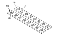
第1光源部150及び第2光源部160は、図8に示されているように、印刷回路基板151、161と印刷回路基板151、161上に配置された複数の発光素子152、162をそれぞれ含み、複数の発光素子それぞれ152、162は印刷回路基板の長さ方向に一列に配列される。このようにホワイトを具現することができる発光素子は、色温度によって様々なタイプがあるが、本発明の実施例において用いられる複数の発光素子は、具体的に、第1光源部150に含まれた複数の発光素子152はウォームホワイト発光素子からなり、第2光源部160に含まれた複数の発光素子162はクールホワイト発光素子からなって、各印刷回路基板151、161上に配列される。
As shown in FIG. 8, the first
図9a乃至図9cは、本発明の一実施例であり、第1光源部と第2光源部にそれぞれ含まれたウォームホワイト発光素子とクールホワイト発光素子の配列構造を示す図である。 FIGS. 9A to 9C are diagrams illustrating an arrangement structure of warm white light emitting elements and cool white light emitting elements included in the first light source unit and the second light source unit, respectively, according to an embodiment of the present invention.
図9aに示されているように、ウォームホワイト発光素子は、第1光源部150の印刷回路基板151に一列に配列され、クールホワイト発光素子は、第2光源部160の印刷回路基板161に一列に配列され得る。
9A, the warm white light emitting elements are arranged in a line on the printed
また、図9bに示されているように、ウォームホワイト発光素子(Warm white LED)とクールホワイト発光素子は、第1光源部150の印刷回路基板151上で印刷回路基板の長さ方向に、交互に一列に配列され、第2光源部160の印刷回路基板161上においても、やはり印刷回路基板の長さ方向に交互に一列に配列され得る。この場合、第1光源部150と第2光源部160のウォームホワイト発光素子(Warm white LED)とクールホワイト発光素子との間の配列構造は格子パターンを有する。
Further, as shown in FIG. 9b, the warm white light emitting element (Warm white LED) and the cool white light emitting element are alternately arranged on the printed
また、図9cに示されているように、ウォームホワイト発光素子(Warm white LED)とクールホワイト発光素子は、第1光源部150と第2光源部160の全体に亘ってランダムに配列され得る。
In addition, as illustrated in FIG. 9 c, the warm white light emitting device (warm white LED) and the cool white light emitting device may be randomly arranged over the entire first
第1光励起フィルム170は、第1導光部110と第1光源部150との間に配置され、第2光励起フィルム180は、第2導光部120と第2光源部160との間に配置される。第1光励起フィルム170及び第2光励起フィルム170は、内部に様々な蛍光物質を含む。
The first
第1光励起フィルム170及び第2光励起フィルム180は、第1光源部150及び第2光源部160から出射された光の波長の一部を変換させ、光の色を変換させる役割をする。
The
図10は、本発明の実施例による光励起フィルムの構造を示す図である。 FIG. 10 is a view showing the structure of a photoexcitation film according to an embodiment of the present invention.
図10のように、光励起フィルム170、180は、透明樹脂171の内部に蛍光物質172が含有されており、透明樹脂の外側には透明な保護フィルム173が積層される。透明な樹脂は主にシリコン樹脂が用いられ、その他、透明性を有する材料であればいずれも使用可能である。
As shown in FIG. 10, the
このような光励起フィルム170、180は、図4において既に説明したため、具体的な説明は省略することにする。
Such photo-
図11は、本発明による実施例であり、光励起フィルムに含まれた蛍光物質の配列構造及び光励起フィルムと光源部との配列構造を示すものである。 FIG. 11 is an example according to the present invention and shows an arrangement structure of fluorescent substances contained in a photoexcitation film and an arrangement structure of a photoexcitation film and a light source part.
図示されているように、第1光励起フィルム170は、第1蛍光物質172aと、第1蛍光物質172aと異なる第2蛍光物質172bを含むが、第1蛍光物質172aと第2蛍光物質172bは、前記光励起フィルム内で互いに区画され、光励起フィルム170の長さ方向に交互に配列される。
As illustrated, the
また、第2光励起フィルム180は、第1蛍光物質182aと、第1蛍光物質182aと異なる第2蛍光物質182bを含むが、第1蛍光物質182aと第2蛍光物質182bは前記第2光励起フィルム180内で互いに区画され、第2光励起フィルム180の長さ方向に交互に配列される。この場合、第1光励起フィルム170及び第2光励起フィルム180に含まれた第1蛍光物質172a、182aと第2蛍光物質172b、182bの配列構造は格子パターンを有する。
In addition, the second
図に示されてはいないが、第1光励起フィルム170及び第2光励起フィルム180に含まれた第1蛍光物質172a、182aと第2蛍光物質172b、182bは、具現しようとする光の色または出射面の特定の位置で特定の色の光を出射しようとするとき、光励起フィルム170、180の長さ方向に局所的にあるいはランダムに配列することができる。
Although not shown in the drawing, the
ただし、第1蛍光物質172a、182aと第2蛍光物質172b、182bを交互に配列する場合、導光板を通じる面光源で光が外部に出射されるとき、色がさらに均等に混合されるため、全体光出射面で多様な色を演出することができるようになる。
However, when the
勿論、色の具現は、発光素子自体で出射される光の色に依存してもよいが、好ましくは、光励起フィルムに含まれた蛍光物質の材料に依存するようにする。 Of course, the implementation of the color may depend on the color of the light emitted from the light emitting element itself, but preferably depends on the material of the fluorescent substance contained in the photoexcitation film.
第1蛍光物質172a、182aと第2蛍光物質172b、182bが交互に配置される場合、図示されているように、光源部150、160の複数の発光素子152、162は、光励起フィルム170、180内に配置された第1蛍光物質172a、182a及び第2蛍光物質172b、182bにそれぞれマッチングされて配置される。従って、複数の発光素子と蛍光物質との間のアラインメント特性が良く、具現しようとする色温度を有する光を出射することができる。
When the
第1蛍光物質172a、182aと第2蛍光物質172b、182bそれぞれは、光源部150、160から出射される特定の波長帯の光に対して吸収し、他の波長帯の光に変換させる。従って、第1蛍光物質172a、182aと第2蛍光物質172b、182bは、外部に出射される光に対して所望する光の色によって調節され得る。
Each of the
このように、光励起フィルムに含まれた蛍光物質は、出射される光の色を変換することができるため、多様な色相の光を作ることができる。 Thus, since the fluorescent substance contained in the photoexcitation film can convert the color of the emitted light, it can produce light of various hues.
以上において、実施例に説明された特徴、構造、効果等は、本発明の少なくとも一つの実施例に含まれ、必ずしも一つの実施例だけに限定されるのではない。さらに、各実施例において例示された特徴、構造、効果等は、実施例の属する分野における通常の知識を有する者により、他の実施例に対しても組み合わせまたは変形されて実施可能である。従って、このような組み合わせと変形に係る内容は、本発明の範囲に含まれるものと解釈されるべきである。 In the above, the features, structures, effects, and the like described in the embodiments are included in at least one embodiment of the present invention, and are not necessarily limited to one embodiment. Furthermore, the features, structures, effects, and the like exemplified in each embodiment can be implemented by combining or modifying other embodiments by those having ordinary knowledge in the field to which the embodiment belongs. Therefore, the contents related to such combinations and modifications should be construed as being included in the scope of the present invention.
また、以上において、実施例を中心に説明したが、これは単に例示であるだけで、本発明を限定するものではなく、本発明の属する分野における通常の知識を有する者であれば、本実施例の本質的な特性から外れない範囲で、以上に例示されていない様々な変形と応用が可能であることが分かる。例えば、実施例に具体的に示された各構成要素は、変形して実施することができる。そして、このような変形と応用に係る相違点は、添付の請求の範囲において規定する本発明の範囲に含まれるものと解釈されるべきである。 In the above description, the embodiment has been mainly described. However, this is merely an example, and does not limit the present invention. Anyone who has ordinary knowledge in the field to which the present invention belongs can perform the present embodiment. It will be understood that various modifications and applications not described above are possible without departing from the essential characteristics of the examples. For example, each component specifically shown in the embodiments can be implemented by being modified. Such differences in modification and application should be construed as being included in the scope of the present invention as defined in the appended claims.
Claims (11)
前記導光板の下側に配置された反射板と、
前記導光板の側部に光学的に結合された光源部と、
前記導光板と光源部との間に配置された光励起フィルムと、
を含み、
前記光励起フィルムは、区画された複数の領域を含み、
前記複数の領域は、第1蛍光物質を含む第1領域と前記第1蛍光物質とは異なる第2蛍光物質を含む第2領域とを含み、
前記第1領域と前記第2領域とは、交互に配置され、
前記光源部は複数の発光素子を含み、
前記複数の発光素子はウォームホワイト発光素子とクールホワイト発光素子とを含み、
前記ウォームホワイト発光素子は前記第1領域にマッチングして配置され、前記クールホワイト発光素子は前記第2領域にマッチングして配置されることを特徴とする光源装置。 A light guide plate;
A reflector disposed under the light guide plate;
A light source unit optically coupled to a side of the light guide plate;
A photoexcitation film disposed between the light guide plate and the light source unit;
Including
The photoexcitation film includes a plurality of partitioned areas,
The plurality of regions include a first region containing a first fluorescent material and a second region containing a second fluorescent material different from the first fluorescent material,
The first region and the second region are alternately arranged,
The light source unit includes a plurality of light emitting elements,
The plurality of light emitting elements include a warm white light emitting element and a cool white light emitting element ,
The light source device according to claim 1, wherein the warm white light emitting element is disposed to match the first region, and the cool white light emitting element is disposed to match the second region .
前記光源部は、第1光源部と第2光源部とを含み、
前記光励起フィルムは、第1導光板と第1光源部との間に配置された第1光励起フィルムと、前記第2導光板と第2光源部との間に配置された第2光励起フィルムを含むことを特徴とする請求項1乃至6のいずれか1項に記載の光源装置。 The light guide plate includes a first light guide plate and a second light guide plate,
The light source unit includes a first light source unit and a second light source unit,
The light excitation film includes a first light excitation film disposed between the first light guide plate and the first light source unit, and a second light excitation film disposed between the second light guide plate and the second light source unit. the light source device according to claim 1 to 6, characterized in that.
前記透明樹脂層は、拡散材を含むことを特徴とする請求項1乃至9のいずれか1項に記載の光源装置。 The photoexcitation film includes a transparent resin layer containing a fluorescent material and a protective film disposed outside the transparent resin layer,
The transparent resin layer, a light source device according to any one of claims 1 to 9, characterized in that it comprises a diffusion material.
Applications Claiming Priority (4)
| Application Number | Priority Date | Filing Date | Title |
|---|---|---|---|
| KR10-2010-0033040 | 2010-04-10 | ||
| KR1020100033039A KR101652818B1 (en) | 2010-04-10 | 2010-04-10 | Light Source Device |
| KR1020100033040A KR101720305B1 (en) | 2010-04-10 | 2010-04-10 | Light Source Device |
| KR10-2010-0033039 | 2010-04-10 |
Publications (3)
| Publication Number | Publication Date |
|---|---|
| JP2011222506A JP2011222506A (en) | 2011-11-04 |
| JP2011222506A5 JP2011222506A5 (en) | 2014-05-15 |
| JP5736218B2 true JP5736218B2 (en) | 2015-06-17 |
Family
ID=44168117
Family Applications (1)
| Application Number | Title | Priority Date | Filing Date |
|---|---|---|---|
| JP2011081409A Active JP5736218B2 (en) | 2010-04-10 | 2011-04-01 | Light source device |
Country Status (4)
| Country | Link |
|---|---|
| US (1) | US9541695B2 (en) |
| EP (2) | EP2378322B1 (en) |
| JP (1) | JP5736218B2 (en) |
| CN (1) | CN102252274B (en) |
Families Citing this family (17)
| Publication number | Priority date | Publication date | Assignee | Title |
|---|---|---|---|---|
| TW201243239A (en) * | 2011-03-17 | 2012-11-01 | Rambus Inc | Lighting assembly with adjustable light output |
| KR101881333B1 (en) * | 2011-08-31 | 2018-07-25 | 엘지이노텍 주식회사 | Lighting module |
| DE102012105445A1 (en) * | 2012-06-22 | 2013-12-24 | Osram Opto Semiconductors Gmbh | Area light source |
| FR3000783B1 (en) * | 2013-01-08 | 2015-03-06 | Commissariat Energie Atomique | PHOTO-ACTIVE STRUCTURE, METHOD OF MANUFACTURING SUCH STRUCTURE AND LIGHTING SYSTEM |
| US20140217447A1 (en) * | 2013-02-07 | 2014-08-07 | Everlight Electronics Co., Ltd. | Phosphor Compositions For Highly Reliable White Light-Emitting Diode Devices |
| JP6265055B2 (en) * | 2014-01-14 | 2018-01-24 | ソニー株式会社 | LIGHT EMITTING DEVICE, DISPLAY DEVICE, AND LIGHTING DEVICE |
| KR20150093283A (en) | 2014-02-06 | 2015-08-18 | 삼성디스플레이 주식회사 | Frame and light source module comprising the same |
| DE202014103047U1 (en) * | 2014-03-27 | 2014-08-20 | Tridonic Jennersdorf Gmbh | Lighting device for generating white light |
| DE102015114910A1 (en) * | 2014-09-19 | 2016-03-24 | Ford Global Technologies, Llc | Photoluminescent vehicle stage light |
| JP6554534B2 (en) * | 2015-03-10 | 2019-07-31 | シャープ株式会社 | Lighting device, display device, and television receiver |
| US9974138B2 (en) | 2015-04-21 | 2018-05-15 | GE Lighting Solutions, LLC | Multi-channel lamp system and method with mixed spectrum |
| CN104879706A (en) * | 2015-06-01 | 2015-09-02 | 上海向隆电子科技有限公司 | Lamp with light guide plate |
| KR102430999B1 (en) * | 2015-06-24 | 2022-08-10 | 쑤저우 레킨 세미컨덕터 컴퍼니 리미티드 | Lighting source module |
| CN105700235A (en) * | 2016-04-13 | 2016-06-22 | 京东方科技集团股份有限公司 | Backlight module and display device |
| JP6963183B2 (en) * | 2018-06-22 | 2021-11-05 | 日亜化学工業株式会社 | Manufacturing method of light emitting module |
| DE202020100855U1 (en) * | 2020-02-18 | 2021-05-25 | Zumtobel Lighting Gmbh | Surface luminaire with direct and indirect light emission |
| JP2023009956A (en) * | 2021-07-08 | 2023-01-20 | 株式会社ジャパンディスプレイ | Lighting device |
Family Cites Families (46)
| Publication number | Priority date | Publication date | Assignee | Title |
|---|---|---|---|---|
| US5506929A (en) * | 1994-10-19 | 1996-04-09 | Clio Technologies, Inc. | Light expanding system for producing a linear or planar light beam from a point-like light source |
| JP3937644B2 (en) * | 1999-03-25 | 2007-06-27 | セイコーエプソン株式会社 | Light source, lighting device, and liquid crystal device using the lighting device |
| JP2004031023A (en) | 2002-06-24 | 2004-01-29 | Kyocera Corp | Backlight liquid crystal display device and display instrument |
| EP1620676A4 (en) * | 2003-05-05 | 2011-03-23 | Philips Solid State Lighting | Lighting methods and systems |
| US7819549B2 (en) * | 2004-05-05 | 2010-10-26 | Rensselaer Polytechnic Institute | High efficiency light source using solid-state emitter and down-conversion material |
| US7213958B2 (en) * | 2004-06-30 | 2007-05-08 | 3M Innovative Properties Company | Phosphor based illumination system having light guide and an interference reflector |
| US7256057B2 (en) * | 2004-09-11 | 2007-08-14 | 3M Innovative Properties Company | Methods for producing phosphor based light sources |
| TWI254821B (en) | 2004-10-01 | 2006-05-11 | Delta Electronics Inc | Backlight module |
| US8125137B2 (en) * | 2005-01-10 | 2012-02-28 | Cree, Inc. | Multi-chip light emitting device lamps for providing high-CRI warm white light and light fixtures including the same |
| US20060268537A1 (en) * | 2005-05-31 | 2006-11-30 | Makoto Kurihara | Phosphor film, lighting device using the same, and display device |
| JP4579065B2 (en) | 2005-06-23 | 2010-11-10 | セイコーインスツル株式会社 | Illumination device and display device including the same |
| JP4469307B2 (en) * | 2005-05-31 | 2010-05-26 | セイコーインスツル株式会社 | Display device |
| US7891852B2 (en) * | 2005-10-17 | 2011-02-22 | Koninklijke Philips Electronics Nv | Illumination system using phosphor remote from light source |
| US7859610B2 (en) * | 2005-12-27 | 2010-12-28 | Panasonic Corporation | Planar lighting and LCD device with a laser light source emitting a linearly-polarized laser beam, optical member to parallelize the beam and a plate-shaped light guide for emitting part of the beam |
| US7682850B2 (en) * | 2006-03-17 | 2010-03-23 | Philips Lumileds Lighting Company, Llc | White LED for backlight with phosphor plates |
| JP2007265716A (en) | 2006-03-28 | 2007-10-11 | Matsushita Electric Ind Co Ltd | Planar light source and liquid crystal display device |
| US7365991B2 (en) * | 2006-04-14 | 2008-04-29 | Renaissance Lighting | Dual LED board layout for lighting systems |
| US20070263409A1 (en) * | 2006-05-09 | 2007-11-15 | Mok Thye L | Light guide plate with reflective light mixing |
| KR101318034B1 (en) * | 2006-08-22 | 2013-10-14 | 엘지디스플레이 주식회사 | Optical unit, back light assembly having the same, and display device having the back light assembly |
| JP2008116849A (en) * | 2006-11-07 | 2008-05-22 | Sony Corp | Display device |
| WO2008060469A2 (en) * | 2006-11-10 | 2008-05-22 | Philips Solid-State Lighting Solutions, Inc. | Methods and apparatus for controlling series-connected leds |
| WO2008142638A1 (en) * | 2007-05-24 | 2008-11-27 | Koninklijke Philips Electronics N.V. | Color-tunable illumination system |
| EP2167866B1 (en) * | 2007-06-14 | 2016-04-13 | Koninklijke Philips N.V. | Led-based luminaire with adjustable beam shape |
| WO2009011922A1 (en) * | 2007-07-18 | 2009-01-22 | Qd Vision, Inc. | Quantum dot-based light sheets useful for solid-state lighting |
| KR100915465B1 (en) | 2007-09-28 | 2009-09-04 | (주) 이지닉스 | Lighting apparatus |
| US7984999B2 (en) * | 2007-10-17 | 2011-07-26 | Xicato, Inc. | Illumination device with light emitting diodes and moveable light adjustment member |
| US7915627B2 (en) * | 2007-10-17 | 2011-03-29 | Intematix Corporation | Light emitting device with phosphor wavelength conversion |
| US7845826B2 (en) * | 2008-01-15 | 2010-12-07 | Skc Haas Display Films Co., Ltd. | Multilayered integrated backlight illumination assembly |
| JP2009211819A (en) | 2008-02-29 | 2009-09-17 | Effect Meiji:Kk | Lighting device for display use |
| WO2009134433A2 (en) * | 2008-05-02 | 2009-11-05 | Light Prescriptions Innovators, Llc | Remote-phosphor led downlight |
| WO2009136351A1 (en) * | 2008-05-07 | 2009-11-12 | Koninklijke Philips Electronics N.V. | Illumination device with led with a self-supporting grid containing luminescent material and method of making the self-supporting grid |
| US9074751B2 (en) * | 2008-06-20 | 2015-07-07 | Seoul Semiconductor Co., Ltd. | Lighting apparatus |
| CN104267458B (en) * | 2008-06-23 | 2018-05-22 | 索尼公司 | Planar light source device and display |
| WO2010002226A2 (en) * | 2008-07-03 | 2010-01-07 | 삼성엘이디 주식회사 | An led package and a backlight unit comprising said led package |
| JP5373914B2 (en) * | 2008-09-23 | 2013-12-18 | コーニンクレッカ フィリップス エヌ ヴェ | Illumination device comprising an electrically variable scattering element |
| WO2010042423A2 (en) * | 2008-10-06 | 2010-04-15 | Light Prescriptions Innovators, Llc | Compact led downlight with cuspated flux-redistribution lens |
| WO2010050274A1 (en) * | 2008-10-27 | 2010-05-06 | シャープ株式会社 | Illuminating apparatus, display apparatus and television receiver |
| US7762704B2 (en) * | 2008-11-19 | 2010-07-27 | Bryter Technologies LLC | Optimized distribution of light extraction from an edge lit light source |
| CN101749654A (en) * | 2008-12-18 | 2010-06-23 | 富士迈半导体精密工业(上海)有限公司 | Lighting device |
| US20100157406A1 (en) * | 2008-12-19 | 2010-06-24 | Qualcomm Mems Technologies, Inc. | System and method for matching light source emission to display element reflectivity |
| WO2010088658A1 (en) * | 2009-02-02 | 2010-08-05 | Ringdale, Inc. | Phosphor composite coated diffuser device and method |
| JP4399678B1 (en) | 2009-02-12 | 2010-01-20 | 鈴木 優一 | Illumination device and display device |
| US7967652B2 (en) * | 2009-02-19 | 2011-06-28 | Cree, Inc. | Methods for combining light emitting devices in a package and packages including combined light emitting devices |
| JP5143770B2 (en) * | 2009-03-02 | 2013-02-13 | 株式会社ジャパンディスプレイイースト | Liquid crystal display |
| US7985000B2 (en) * | 2009-04-08 | 2011-07-26 | Ledengin, Inc. | Lighting apparatus having multiple light-emitting diodes with individual light-conversion layers |
| US8764224B2 (en) * | 2010-08-12 | 2014-07-01 | Cree, Inc. | Luminaire with distributed LED sources |
-
2011
- 2011-02-07 EP EP11153485.5A patent/EP2378322B1/en active Active
- 2011-02-07 EP EP13194373.0A patent/EP2708925B1/en active Active
- 2011-03-04 US US13/040,444 patent/US9541695B2/en active Active
- 2011-03-29 CN CN201110082385.7A patent/CN102252274B/en active Active
- 2011-04-01 JP JP2011081409A patent/JP5736218B2/en active Active
Also Published As
| Publication number | Publication date |
|---|---|
| US9541695B2 (en) | 2017-01-10 |
| EP2708925A1 (en) | 2014-03-19 |
| US20110205727A1 (en) | 2011-08-25 |
| JP2011222506A (en) | 2011-11-04 |
| EP2378322B1 (en) | 2014-01-08 |
| CN102252274B (en) | 2014-09-24 |
| EP2378322A1 (en) | 2011-10-19 |
| EP2708925B1 (en) | 2022-03-30 |
| CN102252274A (en) | 2011-11-23 |
Similar Documents
| Publication | Publication Date | Title |
|---|---|---|
| JP5736218B2 (en) | Light source device | |
| KR101798216B1 (en) | Illumination device with remote luminescent material | |
| JP6083931B2 (en) | Lighting module | |
| US8044570B2 (en) | Lighting device comprising a color conversion unit | |
| TWI550917B (en) | Light emitting device | |
| JP6165155B2 (en) | Illumination unit including a waveguide | |
| RU2673878C2 (en) | Lighting device with optical element having fluid passage | |
| JP2012531047A (en) | LED type lamp and light emission signage | |
| JP2012521066A (en) | Color adjustment device | |
| TW201306325A (en) | White light emitting device, and display apparatus and illumination apparatus using the same | |
| US20140191273A1 (en) | Light-emitting arrangement | |
| KR101652818B1 (en) | Light Source Device | |
| KR102400249B1 (en) | Light emitting module and display including the module | |
| KR100891008B1 (en) | Lighting apparatus of flat panel type | |
| KR100855732B1 (en) | Lighting apparatus of flat panel type | |
| KR101720305B1 (en) | Light Source Device | |
| JP2013161909A (en) | Led lighting unit and led lighting device | |
| KR20120039224A (en) | Led lamp having reflector | |
| US20130271953A1 (en) | Illumination module | |
| KR101874876B1 (en) | Lighting device | |
| KR20130079803A (en) | White light emitting device, display apparatus and illumination apparatus | |
| KR20190063913A (en) | Backlight unit and display device having the same |
Legal Events
| Date | Code | Title | Description |
|---|---|---|---|
| RD03 | Notification of appointment of power of attorney |
Free format text: JAPANESE INTERMEDIATE CODE: A7423 Effective date: 20130319 |
|
| RD04 | Notification of resignation of power of attorney |
Free format text: JAPANESE INTERMEDIATE CODE: A7424 Effective date: 20130514 |
|
| A521 | Request for written amendment filed |
Free format text: JAPANESE INTERMEDIATE CODE: A523 Effective date: 20140401 |
|
| A621 | Written request for application examination |
Free format text: JAPANESE INTERMEDIATE CODE: A621 Effective date: 20140401 |
|
| A977 | Report on retrieval |
Free format text: JAPANESE INTERMEDIATE CODE: A971007 Effective date: 20141120 |
|
| A131 | Notification of reasons for refusal |
Free format text: JAPANESE INTERMEDIATE CODE: A131 Effective date: 20141202 |
|
| A521 | Request for written amendment filed |
Free format text: JAPANESE INTERMEDIATE CODE: A523 Effective date: 20150227 |
|
| TRDD | Decision of grant or rejection written | ||
| A01 | Written decision to grant a patent or to grant a registration (utility model) |
Free format text: JAPANESE INTERMEDIATE CODE: A01 Effective date: 20150407 |
|
| A61 | First payment of annual fees (during grant procedure) |
Free format text: JAPANESE INTERMEDIATE CODE: A61 Effective date: 20150420 |
|
| R150 | Certificate of patent or registration of utility model |
Ref document number: 5736218 Country of ref document: JP Free format text: JAPANESE INTERMEDIATE CODE: R150 |
|
| R250 | Receipt of annual fees |
Free format text: JAPANESE INTERMEDIATE CODE: R250 |
|
| R250 | Receipt of annual fees |
Free format text: JAPANESE INTERMEDIATE CODE: R250 |
|
| R250 | Receipt of annual fees |
Free format text: JAPANESE INTERMEDIATE CODE: R250 |
|
| R250 | Receipt of annual fees |
Free format text: JAPANESE INTERMEDIATE CODE: R250 |
|
| S531 | Written request for registration of change of domicile |
Free format text: JAPANESE INTERMEDIATE CODE: R313531 |
|
| S111 | Request for change of ownership or part of ownership |
Free format text: JAPANESE INTERMEDIATE CODE: R313113 |
|
| R350 | Written notification of registration of transfer |
Free format text: JAPANESE INTERMEDIATE CODE: R350 |
|
| R350 | Written notification of registration of transfer |
Free format text: JAPANESE INTERMEDIATE CODE: R350 |
|
| R250 | Receipt of annual fees |
Free format text: JAPANESE INTERMEDIATE CODE: R250 |
|
| R250 | Receipt of annual fees |
Free format text: JAPANESE INTERMEDIATE CODE: R250 |