JP5734412B2 - Drivetrain and automobile - Google Patents
Drivetrain and automobile Download PDFInfo
- Publication number
- JP5734412B2 JP5734412B2 JP2013506545A JP2013506545A JP5734412B2 JP 5734412 B2 JP5734412 B2 JP 5734412B2 JP 2013506545 A JP2013506545 A JP 2013506545A JP 2013506545 A JP2013506545 A JP 2013506545A JP 5734412 B2 JP5734412 B2 JP 5734412B2
- Authority
- JP
- Japan
- Prior art keywords
- drive train
- parking lock
- clutch
- sleeve
- train according
- Prior art date
- Legal status (The legal status is an assumption and is not a legal conclusion. Google has not performed a legal analysis and makes no representation as to the accuracy of the status listed.)
- Expired - Fee Related
Links
- 230000005540 biological transmission Effects 0.000 claims description 16
- 230000033001 locomotion Effects 0.000 claims description 11
- 210000000078 claw Anatomy 0.000 description 3
- 238000004519 manufacturing process Methods 0.000 description 3
- 230000009467 reduction Effects 0.000 description 3
- 238000006073 displacement reaction Methods 0.000 description 2
- 230000007246 mechanism Effects 0.000 description 2
- 238000000926 separation method Methods 0.000 description 2
- 230000003213 activating effect Effects 0.000 description 1
- 230000009286 beneficial effect Effects 0.000 description 1
- 238000002485 combustion reaction Methods 0.000 description 1
- 238000010276 construction Methods 0.000 description 1
- 230000032258 transport Effects 0.000 description 1
Images


Classifications
-
- B—PERFORMING OPERATIONS; TRANSPORTING
- B60—VEHICLES IN GENERAL
- B60T—VEHICLE BRAKE CONTROL SYSTEMS OR PARTS THEREOF; BRAKE CONTROL SYSTEMS OR PARTS THEREOF, IN GENERAL; ARRANGEMENT OF BRAKING ELEMENTS ON VEHICLES IN GENERAL; PORTABLE DEVICES FOR PREVENTING UNWANTED MOVEMENT OF VEHICLES; VEHICLE MODIFICATIONS TO FACILITATE COOLING OF BRAKES
- B60T1/00—Arrangements of braking elements, i.e. of those parts where braking effect occurs specially for vehicles
- B60T1/005—Arrangements of braking elements, i.e. of those parts where braking effect occurs specially for vehicles by locking of wheel or transmission rotation
-
- B—PERFORMING OPERATIONS; TRANSPORTING
- B60—VEHICLES IN GENERAL
- B60K—ARRANGEMENT OR MOUNTING OF PROPULSION UNITS OR OF TRANSMISSIONS IN VEHICLES; ARRANGEMENT OR MOUNTING OF PLURAL DIVERSE PRIME-MOVERS IN VEHICLES; AUXILIARY DRIVES FOR VEHICLES; INSTRUMENTATION OR DASHBOARDS FOR VEHICLES; ARRANGEMENTS IN CONNECTION WITH COOLING, AIR INTAKE, GAS EXHAUST OR FUEL SUPPLY OF PROPULSION UNITS IN VEHICLES
- B60K7/00—Disposition of motor in, or adjacent to, traction wheel
-
- B—PERFORMING OPERATIONS; TRANSPORTING
- B60—VEHICLES IN GENERAL
- B60K—ARRANGEMENT OR MOUNTING OF PROPULSION UNITS OR OF TRANSMISSIONS IN VEHICLES; ARRANGEMENT OR MOUNTING OF PLURAL DIVERSE PRIME-MOVERS IN VEHICLES; AUXILIARY DRIVES FOR VEHICLES; INSTRUMENTATION OR DASHBOARDS FOR VEHICLES; ARRANGEMENTS IN CONNECTION WITH COOLING, AIR INTAKE, GAS EXHAUST OR FUEL SUPPLY OF PROPULSION UNITS IN VEHICLES
- B60K17/00—Arrangement or mounting of transmissions in vehicles
- B60K17/04—Arrangement or mounting of transmissions in vehicles characterised by arrangement, location or kind of gearing
- B60K17/043—Transmission unit disposed in on near the vehicle wheel, or between the differential gear unit and the wheel
- B60K17/046—Transmission unit disposed in on near the vehicle wheel, or between the differential gear unit and the wheel with planetary gearing having orbital motion
-
- B—PERFORMING OPERATIONS; TRANSPORTING
- B60—VEHICLES IN GENERAL
- B60K—ARRANGEMENT OR MOUNTING OF PROPULSION UNITS OR OF TRANSMISSIONS IN VEHICLES; ARRANGEMENT OR MOUNTING OF PLURAL DIVERSE PRIME-MOVERS IN VEHICLES; AUXILIARY DRIVES FOR VEHICLES; INSTRUMENTATION OR DASHBOARDS FOR VEHICLES; ARRANGEMENTS IN CONNECTION WITH COOLING, AIR INTAKE, GAS EXHAUST OR FUEL SUPPLY OF PROPULSION UNITS IN VEHICLES
- B60K7/00—Disposition of motor in, or adjacent to, traction wheel
- B60K7/0007—Disposition of motor in, or adjacent to, traction wheel the motor being electric
-
- B—PERFORMING OPERATIONS; TRANSPORTING
- B60—VEHICLES IN GENERAL
- B60T—VEHICLE BRAKE CONTROL SYSTEMS OR PARTS THEREOF; BRAKE CONTROL SYSTEMS OR PARTS THEREOF, IN GENERAL; ARRANGEMENT OF BRAKING ELEMENTS ON VEHICLES IN GENERAL; PORTABLE DEVICES FOR PREVENTING UNWANTED MOVEMENT OF VEHICLES; VEHICLE MODIFICATIONS TO FACILITATE COOLING OF BRAKES
- B60T1/00—Arrangements of braking elements, i.e. of those parts where braking effect occurs specially for vehicles
- B60T1/02—Arrangements of braking elements, i.e. of those parts where braking effect occurs specially for vehicles acting by retarding wheels
- B60T1/06—Arrangements of braking elements, i.e. of those parts where braking effect occurs specially for vehicles acting by retarding wheels acting otherwise than on tread, e.g. employing rim, drum, disc, or transmission or on double wheels
-
- B—PERFORMING OPERATIONS; TRANSPORTING
- B60—VEHICLES IN GENERAL
- B60W—CONJOINT CONTROL OF VEHICLE SUB-UNITS OF DIFFERENT TYPE OR DIFFERENT FUNCTION; CONTROL SYSTEMS SPECIALLY ADAPTED FOR HYBRID VEHICLES; ROAD VEHICLE DRIVE CONTROL SYSTEMS FOR PURPOSES NOT RELATED TO THE CONTROL OF A PARTICULAR SUB-UNIT
- B60W30/00—Purposes of road vehicle drive control systems not related to the control of a particular sub-unit, e.g. of systems using conjoint control of vehicle sub-units
- B60W30/18—Propelling the vehicle
- B60W30/18181—Propulsion control with common controlling member for different functions
-
- F—MECHANICAL ENGINEERING; LIGHTING; HEATING; WEAPONS; BLASTING
- F16—ENGINEERING ELEMENTS AND UNITS; GENERAL MEASURES FOR PRODUCING AND MAINTAINING EFFECTIVE FUNCTIONING OF MACHINES OR INSTALLATIONS; THERMAL INSULATION IN GENERAL
- F16H—GEARING
- F16H63/00—Control outputs from the control unit to change-speed- or reversing-gearings for conveying rotary motion or to other devices than the final output mechanism
- F16H63/02—Final output mechanisms therefor; Actuating means for the final output mechanisms
- F16H63/30—Constructional features of the final output mechanisms
- F16H63/3069—Interrelationship between two or more final output mechanisms
-
- F—MECHANICAL ENGINEERING; LIGHTING; HEATING; WEAPONS; BLASTING
- F16—ENGINEERING ELEMENTS AND UNITS; GENERAL MEASURES FOR PRODUCING AND MAINTAINING EFFECTIVE FUNCTIONING OF MACHINES OR INSTALLATIONS; THERMAL INSULATION IN GENERAL
- F16H—GEARING
- F16H63/00—Control outputs from the control unit to change-speed- or reversing-gearings for conveying rotary motion or to other devices than the final output mechanism
- F16H63/02—Final output mechanisms therefor; Actuating means for the final output mechanisms
- F16H63/30—Constructional features of the final output mechanisms
- F16H63/34—Locking or disabling mechanisms
- F16H63/3416—Parking lock mechanisms or brakes in the transmission
- F16H63/3441—Parking locks engaging axially
-
- B—PERFORMING OPERATIONS; TRANSPORTING
- B60—VEHICLES IN GENERAL
- B60K—ARRANGEMENT OR MOUNTING OF PROPULSION UNITS OR OF TRANSMISSIONS IN VEHICLES; ARRANGEMENT OR MOUNTING OF PLURAL DIVERSE PRIME-MOVERS IN VEHICLES; AUXILIARY DRIVES FOR VEHICLES; INSTRUMENTATION OR DASHBOARDS FOR VEHICLES; ARRANGEMENTS IN CONNECTION WITH COOLING, AIR INTAKE, GAS EXHAUST OR FUEL SUPPLY OF PROPULSION UNITS IN VEHICLES
- B60K7/00—Disposition of motor in, or adjacent to, traction wheel
- B60K2007/0038—Disposition of motor in, or adjacent to, traction wheel the motor moving together with the wheel axle
-
- B—PERFORMING OPERATIONS; TRANSPORTING
- B60—VEHICLES IN GENERAL
- B60K—ARRANGEMENT OR MOUNTING OF PROPULSION UNITS OR OF TRANSMISSIONS IN VEHICLES; ARRANGEMENT OR MOUNTING OF PLURAL DIVERSE PRIME-MOVERS IN VEHICLES; AUXILIARY DRIVES FOR VEHICLES; INSTRUMENTATION OR DASHBOARDS FOR VEHICLES; ARRANGEMENTS IN CONNECTION WITH COOLING, AIR INTAKE, GAS EXHAUST OR FUEL SUPPLY OF PROPULSION UNITS IN VEHICLES
- B60K7/00—Disposition of motor in, or adjacent to, traction wheel
- B60K2007/0092—Disposition of motor in, or adjacent to, traction wheel the motor axle being coaxial to the wheel axle
Landscapes
- Engineering & Computer Science (AREA)
- Mechanical Engineering (AREA)
- Transportation (AREA)
- Chemical & Material Sciences (AREA)
- Combustion & Propulsion (AREA)
- General Engineering & Computer Science (AREA)
- Automation & Control Theory (AREA)
- Arrangement Or Mounting Of Propulsion Units For Vehicles (AREA)
- Gear-Shifting Mechanisms (AREA)
- Motor Power Transmission Devices (AREA)
- Braking Arrangements (AREA)
- Mechanical Operated Clutches (AREA)
- Hybrid Electric Vehicles (AREA)
- Connection Of Motors, Electrical Generators, Mechanical Devices, And The Like (AREA)
- Arrangement And Driving Of Transmission Devices (AREA)
- Retarders (AREA)
- Electric Propulsion And Braking For Vehicles (AREA)
Description
本発明は、ドライブトレインを選択的にロックするパーキングロックと、電動機および動力車軸とを有し、動力車軸が、電動機に永久的に駆動連結され、切り離しクラッチを介して自動車の少なくとも1つの車輪に選択的に駆動連結可能である自動車のドライブトレインに関する。 The present invention includes a parking lock that selectively locks a drive train, an electric motor and a power axle, and the power axle is permanently driven and connected to the electric motor and is connected to at least one wheel of the automobile via a disconnect clutch. The present invention relates to an automobile drive train that can be selectively connected to a drive.
上述したタイプのドライブトレインは、特に、電気自動車またはハイブリッド車で使用される。この場合、パーキングロックは、エンジンが切られたときの状態に車両を固定するように働く。切り離しクラッチは、例えば、アイドリング状態にするために、電動機と車輪との係合を解除するように働く。例えば、ハイブリッド車の場合、車輪と電動機との切り離しは、内燃機関単独での車両の高速駆動時に電動機が回転するのを防止するように働きうる。しかしながら、例えば、故障時の場合など、車輪と電動機との間の機械的接続を解除できるようにするために、このような切り離しクラッチは、純粋な電気自動車において重要である。 Drive trains of the type described above are used in particular in electric vehicles or hybrid vehicles. In this case, the parking lock functions to fix the vehicle in the state when the engine is turned off. The disengagement clutch works to release the engagement between the electric motor and the wheel, for example, in order to enter an idling state. For example, in the case of a hybrid vehicle, the separation of the wheel and the electric motor can work to prevent the electric motor from rotating when the vehicle is driven at high speed by the internal combustion engine alone. However, such a disengagement clutch is important in a pure electric vehicle in order to be able to release the mechanical connection between the wheel and the motor, for example in the event of a failure.
自動車においてドライブトレインが利用可能な全空間は、一般に非常に限られている。加えて、パーキングロックおよび切り離しクラッチのそれぞれの機能は常に利用可能でなければならない。パーキングロックおよび切り離しクラッチを作動するために、従来、別々のアクチュエータが設けられているため、ドライブトレインの製造コストが増し、全空間のうちさらに多くの空間が使われてしまう。 The total space in which a drive train can be used in an automobile is generally very limited. In addition, the respective functions of the parking lock and the release clutch must always be available. Conventionally, separate actuators are provided to operate the parking lock and the release clutch, which increases the manufacturing cost of the drive train and uses more of the total space.
したがって、本発明の目的は、高信頼性の動作とともに、単純かつ小型の構造のドライブトレインを作り出すことである。 Accordingly, an object of the present invention is to create a drive train having a simple and small structure with a high reliability operation.
この目的は、自動車のドライブトレインであって、ドライブトレインを選択的にロックするパーキングロックと、電動機および動力車軸とを有し、動力車軸が、電動機に永久的に駆動連結され、切り離しクラッチを介して、自動車の少なくとも1つの車輪に選択的に駆動連結可能であり、パーキングロックおよび切り離しクラッチが、共通のアクチュエータによって作動されうるドライブトレインによって達成される。 The purpose of the present invention is an automobile drive train, which has a parking lock for selectively locking the drive train, an electric motor and a power axle, and the power axle is permanently connected to the electric motor via a disconnect clutch. Thus, the vehicle can be selectively drive-coupled to at least one wheel of the vehicle, and the parking lock and release clutch are achieved by a drive train that can be actuated by a common actuator.
本発明によれば、パーキングロックおよび切り離しクラッチは、共通のアクチュエータによって作動されうる。したがって、2つの前記機能ユニットの各々に、別々のアクチュエータが設けられない。パーキングロックおよび切り離しクラッチの両方を作動するように働く共通のアクチュエータを使用すると、必要なコンポーネント数が減ることで、ドライブトレインの製造コストおよび組み立てコストに有利な影響を及ぼす。加えて、本発明によるドライブトレインは、既知の構造の同等のドライブトレインより小型のデザインのものでありうる。 According to the invention, the parking lock and the release clutch can be actuated by a common actuator. Therefore, a separate actuator is not provided for each of the two functional units. The use of a common actuator that serves to actuate both the parking lock and the disengagement clutch has a beneficial effect on drivetrain manufacturing and assembly costs by reducing the number of components required. In addition, the drive train according to the present invention can be of a smaller design than an equivalent drive train of known construction.
パーキングロックおよび切り離しクラッチは、軸方向に、特に、共通の軸に沿って作動されうる。 The parking lock and the release clutch can be actuated axially, in particular along a common axis.
パーキングロック、切り離しクラッチおよび/または動力車軸は、同軸に配設されてもよい。 The parking lock, disconnect clutch and / or power axle may be arranged coaxially.
ドライブトレインの確実な動作を常時確保するために、アクチュエータは、切り離しクラッチが閉状態にあるときのみ、パーキングロックが作動可能なように構成されてもよい。このような構成により、パーキングロックが係合されると、車輪が動力車軸に自動的に連結されるようになる。これは、上述した自動安全機能がない場合、パーキングロックが作動され、前記コンポーネントがロックされていても、切り離しクラッチが開状態のまま車輪が自由に回転しうるため、パーキングロックが電動機または動力車軸をロックすることによって、ドライブトレインがロックされるように配設される場合、特に重要である。 In order to ensure reliable operation of the drive train at all times, the actuator may be configured such that the parking lock can be activated only when the release clutch is in the closed state. With such a configuration, when the parking lock is engaged, the wheels are automatically connected to the power axle. This is because, if the automatic safety function described above is not provided, the parking lock is activated, and even if the components are locked, the wheel can freely rotate while the release clutch is open. It is particularly important if the drive train is arranged to be locked by locking the.
パーキングロックを作動するための作動運動および切り離しクラッチを開くための作動運動は、特に、反対方向に向けられる。 The actuating movement for actuating the parking lock and the actuating movement for opening the disengagement clutch are in particular directed in opposite directions.
切り離しクラッチは、軸方向に横断可能なクラッチ部を備えてもよく、このクラッチ部は、自動車の車輪に回転可能に固定されて連結された車軸部分に割り当てられる。例えば、前記クラッチ部は、スリーブ状のデザインのものであり、回転可能に固定されるが、軸方向に横断可能になるようにリニア軸受によって車軸部分に連結される。 The disengagement clutch may include a clutch portion that can be traversed in the axial direction, and this clutch portion is assigned to an axle portion that is rotatably fixed to and connected to a vehicle wheel. For example, the clutch portion has a sleeve-like design and is rotatably fixed, but is connected to the axle portion by a linear bearing so as to be traversable in the axial direction.
アクチュエータは、軸方向に変位可能なスライドスリーブを含んでもよく、このスライドスリーブは、動力車軸を部分的に取り囲み、動力車軸によって少なくとも部分的に同軸方向に案内される作動シャフトによって移動されうる。言い換えれば、半径方向に見た場合、動力車軸は、スライドスリーブと作動シャフトとの間に少なくとも部分的に配設される。スライドスリーブの作動機構の単純なデザイン構成において、スライドスリーブは、半径方向に少なくとも部分的に伸びるピンによって軸方向に変位可能なように作動シャフトに連結される。 The actuator may include an axially displaceable slide sleeve that may be moved by an actuating shaft that partially surrounds the power axle and is at least partially guided coaxially by the power axle. In other words, when viewed in the radial direction, the power axle is at least partially disposed between the slide sleeve and the actuation shaft. In a simple design configuration of the slide sleeve actuating mechanism, the slide sleeve is connected to the actuating shaft so as to be axially displaceable by a pin extending at least partially in the radial direction.
切り離しクラッチを作動するために、スライドスリーブは、クラッチ部を軸方向に横断させるように、選択的に、例えば、直接的または間接的に、切り離しクラッチの軸方向に横断可能なクラッチ部に連結可能であってもよい。 In order to operate the disengagement clutch, the slide sleeve can be selectively connected, for example directly or indirectly, to the clutch part traversable in the axial direction of the disengagement clutch so as to traverse the clutch part in the axial direction. It may be.
アクチュエータは、切り離しクラッチを閉状態にするバイアスを生成するように働く弾性要素を備えてもよい。例えば、弾性要素は、ばねであり、ばねは、作動シャフトおよびスライドスリーブによって軸方向に横断可能なクラッチ部に作用し、アクチュエータによる能動的な作動がない場合、クラッチ部を押圧して、切り離しクラッチを閉状態にする。 The actuator may comprise an elastic element that serves to generate a bias that closes the disengagement clutch. For example, the elastic element is a spring, and the spring acts on a clutch part that can be traversed in the axial direction by an operating shaft and a slide sleeve. Is closed.
電動機と動力車軸の省スペース連結は、例えば、遊星トランスミッションを備えてもよい。この実施形態は、特に、回転子と動力車軸とが同軸に配設され、動力車軸が回転子を少なくとも部分的に通って延びる場合に有用である。 The space-saving connection between the electric motor and the power axle may include, for example, a planetary transmission. This embodiment is particularly useful when the rotor and power axle are arranged coaxially and the power axle extends at least partially through the rotor.
ドライブトレインの効率的なロックは、パーキングロックが作動されると、遊星トランスミッションがロックされるように構成されれば達成される。 Efficient locking of the drive train is achieved if the planetary transmission is configured to lock when the parking lock is activated.
1つの実施形態によれば、パーキングロックは、電動機の回転子に回転可能に固定されたパーキングロックスリーブを備える。回転子が、例えば、減速歯車として具現化された遊星トランスミッションの太陽歯車に回転可能に固定されるようにさらに連結され、動力車軸が、遊星トランスミッションの遊星枠に回転可能に固定されるように連結され、またはその逆に連結されれば、パーキングロックを作動することで動力車軸に直接パーキングロックスリーブを連結および回転可能に固定することによって、ドライブトレインがロックされうる。この状況において、遊星トランスミッションの「入力」および「出力」が回避され、関与するコンポーネントの回転が、例えば、2段遊星歯車によって与えられる遊星トランスミッションの減速により防止される。 According to one embodiment, the parking lock includes a parking lock sleeve that is rotatably fixed to the rotor of the electric motor. The rotor is further coupled to be rotatably fixed to a planetary transmission sun gear, for example embodied as a reduction gear, and the power axle is rotatably coupled to the planetary frame of the planetary transmission. If connected, or vice versa, the drive train can be locked by activating the parking lock to connect and rotate the parking lock sleeve directly to the power axle. In this situation, the “input” and “output” of the planetary transmission are avoided and the rotation of the components involved is prevented, for example, by the deceleration of the planetary transmission provided by the two-stage planetary gear.
パーキングロックスリーブは、スライドスリーブによって選択的に軸方向に横断可能であり、動力車軸に回転可能に固定されて連結され、パーキングロックスリーブと係合状態にもたらされうるスリーブによって、動力車軸に連結されうる。 The parking lock sleeve can be selectively traversed axially by a slide sleeve, is rotatably connected to the power axle and is connected to the power axle by a sleeve that can be brought into engagement with the parking lock sleeve. Can be done.
多くの場合、電気後車軸ドライブを有する車両において電気ドライブが利用可能な全空間は、自動車の最低地上高の要求により、厳しく制限されている。要求された車軸運動学およびその結果得られる車軸構造により、ドライブトレインに与えられる全空間を規定するさらなる制約がかかる。したがって、さらなる実施形態によれば、電動機は固定子および回転子を備え、パーキングロックおよび切り離しクラッチは、回転子に少なくとも部分的に、特に、全体的に配設される。パーキングロックおよび切り離しクラッチを回転子の内部に少なくとも部分的に統合すると、特に、電動機の軸方向に見た場合、ドライブトレインの構成が非常に小型のものになる。さらに、ドライブトレインの機能コンポーネントが空間的に近接することにより、「パッケージ」が最適化され、従来のドライブトレインより組み立てが容易になる。 In many cases, the total space available for an electric drive in a vehicle with an electric rear axle drive is severely limited by the minimum ground clearance requirements of the automobile. The required axle kinematics and the resulting axle structure places additional constraints on the overall space provided to the drivetrain. Thus, according to a further embodiment, the electric motor comprises a stator and a rotor, and the parking lock and the release clutch are arranged at least partly, in particular entirely, on the rotor. When the parking lock and the release clutch are at least partially integrated inside the rotor, the drive train configuration is very small, especially when viewed in the axial direction of the motor. In addition, the close proximity of the functional components of the drive train optimizes the “package” and makes it easier to assemble than conventional drive trains.
1つの実施形態によれば、回転子は、中空シャフトとして具現化され、この中空シャフトを通って動力車軸が少なくとも部分的に延びる。中空シャフトはまた、パーキングロックおよび切り離しクラッチを収容してもよい。 According to one embodiment, the rotor is embodied as a hollow shaft through which the power axle extends at least partially. The hollow shaft may also accommodate a parking lock and disconnect clutch.
本発明は、さらに、自動車、特に、前車軸および後車軸と、上述した実施形態の少なくとも1つによるドライブトレインとを有する自動車であって、前車軸および/または後車軸は、いずれの場合も、2つの動力車軸を備え、動力車軸の各々に別々の電動機が割り当てられる自動車に関する。言い換えれば、前車軸および/または後車軸の各ハーフシャフトに別々のドライブトレインが割り当てられるため、車軸のそれぞれの個々の車輪に駆動トルクが明確かつ個別に送り出せる。これは「トルクベクタリング」とも呼ばれる。加えて、この構成では、車軸につき電動機が1つのみの自動車や、自動車の推進用の電動機が1つのみの自動車より小型の電動機を使用可能である。 The invention further relates to a motor vehicle, in particular a motor vehicle having a front axle and a rear axle, and a drive train according to at least one of the embodiments described above, wherein the front axle and / or the rear axle are in any case The present invention relates to a motor vehicle that includes two power axles, and each motor axle is assigned a separate electric motor. In other words, a separate drive train is assigned to each half shaft of the front axle and / or the rear axle, so that driving torque can be clearly and individually sent to each individual wheel of the axle. This is also called “torque vectoring”. In addition, in this configuration, it is possible to use a smaller motor than an automobile having only one electric motor per axle or an automobile having only one electric motor for driving the automobile.
本発明のさらなる実施形態は、特許請求の範囲、本明細書および図面において明示される。 Further embodiments of the invention are specified in the claims, the description and the drawings.
本発明は、添付の図面を参照しながら、有益な実施形態を基本として例示的にのみ説明される。 The invention will now be described by way of example only on the basis of advantageous embodiments with reference to the accompanying drawings.
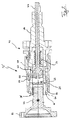
図1は、電動機12を有するドライブトレイン10を示す。電動機12は、自動車の後車軸のハーフシャフトを駆動するように働く。後車軸は、対称的な構造のものであり、すなわち、電動機は、後車軸のもう一方のハーフシャフト(図示せず)に同様に割り当てられる。したがって、後車軸に接続された車輪(図示せず)の各々に別々の電動機が割り当てられるため、これらの車輪には、個々におよび互いに別々に駆動トルクが供給されうる。これにより、「トルクベクタリング」が可能になり、すなわち、自動車の運転動力学を任意の所与の時間における条件に適応可能にするために、運転状況に特有のものである後車軸の車輪に駆動トルクが分配される。
FIG. 1 shows a drive train 10 having an
電動機12は、固定子14と、回転子16とを備える。回転子16は、軸受18によってハウジング20に支持される。
The
電動機12によって発生した駆動トルクは、回転子16から中空シャフト部分22を介して遊星トランスミッション24へ伝達される。遊星トランスミッション24は、太陽歯車26を備え、太陽歯車26は、中空シャフト部分22に接続され、第1の遊星歯車28と噛み合う。第1の遊星歯車28は、第2の遊星歯車28’に回転可能に固定され、第2の遊星歯車28’の直径は、第1の遊星歯車28より小さい。第2の遊星歯車28’は、ハウジング20において回転できないように固定されたリング歯車30と噛み合う。遊星歯車28、28’は両方で、遊星枠32に回転可能に配設された2段遊星歯車28’’を形成する。遊星歯車28’’の2段構造により、遊星トランスミッション24は、太陽歯車26の駆動運動によって遊星枠32のギアダウン運転をもたらす減速歯車である。
The drive torque generated by the
遊星枠32は、中間シャフト34に回転可能に固定され、中間シャフト34は、回転子16内に同軸に延び、事実上、回転子を長手方向に貫通する。切り離しクラッチ36は、遊星トランスミッション24から離れた中間シャフト34の一端に配設される。爪クラッチとして具現化される切り離しクラッチ36はクラッチ部38を備え、クラッチ部38は、中間シャフト34に回転可能に固定され、軸方向に変位可能なクラッチ部38’に選択的に連結可能である。切り離しクラッチ36は、閉状態に示されている。
The planetary frame 32 is rotatably fixed to the
リニア軸受40によって、クラッチ部38’は軸方向に変位可能であるが、車軸部分42に回転可能に固定されるように接続され、車軸部分42は、回転子16内に延び、自動車の車輪を固定するためのフランジ44と一体に形成される。車軸部分42は、軸受18’によって回転子16に支持される。
The
ドライブトレイン10は、例えば、駐車時に自動車の動きを防止するために、パーキングロック46によってロックされうる。パーキングロック46は、回転子16に回転可能に固定されたパーキングロックスリーブ48と、軸方向に変位可能であるが、回転可能に固定されたリニア軸受40’によって中間シャフト34に連結されたスリーブ50とを備える。
The drive train 10 can be locked by a
軸方向に横断可能なクラッチ部38’のように、スリーブ50は、電動機12および中間シャフト34の回転軸Rの軸方向にアクチュエータ52によって変位可能である。このような変位は、軸方向に変位可能なスライドスリーブ58にピン56によって連結される作動シャフト54によって発生されうる。スライドスリーブ58は、スリーブ50に直接接続される。切り離しクラッチ36は、クラッチ部38’に接続された圧力スリーブ60を有するボール59によって選択的に連結することで作動される。
Like the
以下、アクチュエータ52の動作原理についてさらに詳細に説明する。
Hereinafter, the operation principle of the
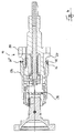
図2は、アクチュエータのわずかに修正された実施形態52’を示す。特に、中間シャフト34は、アクチュエータ52のものと対比すると、ピン56が貫通する細長い孔62が1つしかない。しかしながら、機能的に、アクチュエータ52、52’は実質的に同一である。特に、任意の数のピン56および対応する細長い孔62が設けられてもよい。
FIG. 2 shows a slightly modified embodiment 52 'of the actuator. In particular, the
図2において、アクチュエータ52’は、切り離しクラッチ36の閉位置を規定する。パーキングロック46は開かれている。切り離しクラッチ36を開くために、スライドスリーブ58は、図2に示す位置から左へ変位されなければならない。このような変位は、作動シャフト54の適切な並進運動によって発生され、ピン56を介してスライドスリーブ58に伝達される。中間シャフト34を通って同軸に延び、スライドスリーブ58の作動に必要とされる作動シャフト54の動きは、より詳細には図示していない機構によって作り出される。
In FIG. 2, the
作動シャフト54が左側に移動するとき、アクチュエータ52’が開運動を要求しない限り、切り離しクラッチ36、ひいては、パーキングロック46を閉位置に保つバイアスをばね64が発生するため、ばね64によって生じるばね力に打ち勝たなければならない。
When the actuating
スライドスリーブ58が左側に移動するにつれ、スライドスリーブ58が圧力スリーブ60に接続された保持リング66に当たるため、圧力スリーブ60も同様に左側に移動する。次に、圧力スリーブ60は、クラッチ部38’に配設された保持リング66’に当たる。すでに記載したように、クラッチ部38’は軸方向に横断可能であるため、スライドスリーブ58が図2に示す状況から左側に作動運動すると、クラッチ部38’はフランジ44へ移動するため、クラッチ部38、38’の爪68の係合が解除される。次に、車軸部分42は、電動機12から切り離される。この状態は、図3のアクチュエータ52によって示されている。
As the
切り離しクラッチ36を閉じるために、スライドスリーブ58は再度右側に移動する。特に、円周方向に均一に分散させて配設される複数のボール59が基本的に設けられてもよいという暗黙の了解の下、圧力スリーブ60は、ボール59によってスライドスリーブ58に連結され、結果的に、右側に移動される。クラッチ部38、38’が完全に係合され、クラッチ部38’が軸方向に運動できなくなると、圧力スリーブ60がさらに右側へ移動する動きがロックされる。このとき、再度、図2に示す状態に達する。
In order to close the
スライドスリーブ58が右側にさらに移動する場合、ボール59は半径方向内向きに押圧されるため、軸方向への運動に関しては、圧力スリーブ60とスライドスリーブ58との連結が解消される。
When the
図4は、パーキングロック46の作動状態を示す。パーキングロック46を作動するために、スライドスリーブ58は、図2に示す状況から右側にさらに移動する。スライドスリーブ58は、右側に移動する際、スリーブ50上の対応するウェブ72と相互作用するショルダ70上にわたってスライドスリーブ58とともにスリーブ50を移送する。スライドスリーブ58およびスリーブ50が横断してつながれるということは、スリーブ50がパーキングロックスリーブ48と係合状態にもたらされることを意味する。すでに記載したように、パーキングロックスリーブ48は、回転子16に回転可能に固定されているため、遊星トランスミッション24は回避され、すなわち、遊星枠32および太陽歯車26が最終的に連結され、互いに対して回転可能に固定される。遊星トランスミッション24は、遊星歯車28、28’の直径と異なることで、減速歯車として機能するため、例えば、自動車が配置されているパーキングロットの斜面によって生じる勾配抵抗が自動車に作用することで、例えば、遊星枠32にトルクが作用するときにロックが起こる。
FIG. 4 shows the operating state of the
図4は、切り離しクラッチ36が閉じられるときのみ、パーキングロック46の作動が可能になることを示す。これにより、ドライブトレイン10の構造が高信頼性および安全なものになる。
FIG. 4 shows that the
パーキングロック46を開くために、スライドスリーブ58は、図3に示す状況から左側に変位され、スライドスリーブは、スリーブ50に取り付けられた保持リング66’’によってスライドスリーブ58とともにスリーブ50を移送する。それにより、スリーブ50とパーキングロックスリーブ48との間の回転可能に固定された接続が取り消され、遊星トランスミッション24はロックされた状態ではなくなる。
To open the
上記説明から、切り離しクラッチ36およびパーキングロック46が所定の方法でのみ作動可能であるため、アクチュエータ52、52’が最初にドライブトレイン10を確実に動作させることが分かる。
From the above description, it can be seen that the
さらに、軸方向に移動可能なコンポーネントが同軸に配設されるため、アクチュエータ52、52’の構造は非常に堅牢である。また、これにより、小型で半径方向に「入れ子式」の構造のアクチュエータ52、52’が得られる。アクチュエータ52、52’の小型構造により、回転子16にすべて配設することができることで、特に、軸方向において、全ドライブトレイン10の構造が小型になる。さらに、アクチュエータ52、52’は、回転子16内で保護される。
Furthermore, since the axially movable components are arranged coaxially, the structure of the
最終的に、上述したドライブトレイン10の構成により、車両に簡単に装着可能なモジュールが得られる。すなわち、ドライブトレイン10は、1つの小型「パッケージ」に動力ユニットおよび安全性関連の機能ユニットの両方を備える。また、これにより、自動車の車軸の各車輪に別々のドライブトレイン10を割り当てることができる。 Finally, a module that can be easily mounted on a vehicle is obtained by the configuration of the drive train 10 described above. That is, the drive train 10 includes both a power unit and a safety-related functional unit in one small “package”. This also allows a separate drive train 10 to be assigned to each wheel of the vehicle axle.
上述した利点に加えて、ドライブトレイン10のさらなる顕著な特徴として、切り離しクラッチ36およびパーキングロック46の両方を作動させるために、1つのアクチュエータ52、52’しか要求されないため、コスト効率が良い構造である点が挙げられる。製造コストおよび組み立てコストの削減の他にも、システム全体の故障しやすさも低減される。
In addition to the advantages described above, a further salient feature of the drivetrain 10 is that it requires a
10 ドライブトレイン
12 電動機
14 固定子
16 回転子
18,18’ 軸受
20 ハウジング
22 中空シャフト部分
24 遊星トランスミッション
26 太陽歯車
28,28’,28’’ 遊星歯車
30 リング歯車
32 遊星枠
34 中間シャフト
36 切り離しクラッチ
38,38’ クラッチ部
40,40’ リニア軸受
42 車軸部分
44 フランジ
46 パーキングロック
48 パーキングロックスリーブ
50 スリーブ
52,52’ アクチュエータ
54 作動シャフト
56 ピン
58 スライドスリーブ
59 ボール
60 圧力スリーブ
62 細長い孔
64 ばね
66,66’,66’’ 保持リング
68 爪
70 ショルダ
72 ウェブ
R 回転軸
DESCRIPTION OF SYMBOLS 10
Claims (16)
Applications Claiming Priority (3)
| Application Number | Priority Date | Filing Date | Title |
|---|---|---|---|
| US32959810P | 2010-04-30 | 2010-04-30 | |
| US61/329,598 | 2010-04-30 | ||
| PCT/EP2011/002157 WO2011134673A1 (en) | 2010-04-30 | 2011-04-29 | Drive train |
Publications (2)
| Publication Number | Publication Date |
|---|---|
| JP2013531765A JP2013531765A (en) | 2013-08-08 |
| JP5734412B2 true JP5734412B2 (en) | 2015-06-17 |
Family
ID=44306274
Family Applications (1)
| Application Number | Title | Priority Date | Filing Date |
|---|---|---|---|
| JP2013506545A Expired - Fee Related JP5734412B2 (en) | 2010-04-30 | 2011-04-29 | Drivetrain and automobile |
Country Status (7)
| Country | Link |
|---|---|
| US (1) | US9302655B2 (en) |
| EP (1) | EP2563612B1 (en) |
| JP (1) | JP5734412B2 (en) |
| KR (1) | KR101421865B1 (en) |
| CN (1) | CN102858578B (en) |
| DE (1) | DE102011100060A1 (en) |
| WO (1) | WO2011134673A1 (en) |
Families Citing this family (15)
| Publication number | Priority date | Publication date | Assignee | Title |
|---|---|---|---|---|
| CN104470746B (en) * | 2012-05-10 | 2017-04-19 | 戈尔德霍弗股份公司 | Drives for motor vehicles |
| WO2016111186A1 (en) * | 2015-01-07 | 2016-07-14 | トヨタ自動車株式会社 | Support structure for rotating shafts of vehicle |
| JP6743742B2 (en) * | 2017-03-29 | 2020-08-19 | トヨタ自動車株式会社 | Hybrid vehicle |
| EP3647539A1 (en) * | 2018-10-30 | 2020-05-06 | Siemens Aktiengesellschaft | Safety apparatus |
| DE102019108845A1 (en) * | 2019-04-04 | 2020-10-08 | Fte Automotive Gmbh | Differential gear for a drive axle of a motor vehicle |
| CN114096431B (en) * | 2019-05-08 | 2023-11-03 | 依维柯股份公司 | Drive axle for a vehicle having a first axle and a second axle as a lift axle |
| US11198359B2 (en) * | 2019-12-16 | 2021-12-14 | Schaeffler Technologies AG & Co. KG | Dual motor coaxial e-axle with rotor shaft locking mechanism |
| DE102020102252A1 (en) | 2020-01-30 | 2021-08-05 | Schaeffler Technologies AG & Co. KG | Drive train of a motor vehicle with a parking lock |
| US11241393B2 (en) | 2020-05-11 | 2022-02-08 | Zoser B. Salama | Organosilicon carriers for use in treating infections and/or diseases caused by SARS viruses |
| DE102021118661A1 (en) | 2021-07-20 | 2023-01-26 | Audi Aktiengesellschaft | powertrain and motor vehicle |
| DE102022000026A1 (en) * | 2022-01-03 | 2023-07-06 | Mercedes-Benz Group AG | Wheel hub drive for a motor vehicle, in particular for a motor vehicle, and motor vehicle |
| DE102022000035B4 (en) * | 2022-01-03 | 2026-01-08 | Mercedes-Benz Group AG | Wheel hub drive for a motor vehicle, in particular for a car, as well as motor vehicle |
| DE102022101279B4 (en) | 2022-01-20 | 2025-06-12 | Bayerische Motoren Werke Aktiengesellschaft | Motor vehicle with a coupling gear and a functionally secured parking lock device |
| DE102022104217B4 (en) * | 2022-02-23 | 2023-11-16 | Bayerische Motoren Werke Aktiengesellschaft | Motor vehicle with a coupling gear and a parking lock device |
| DE102024205198A1 (en) * | 2024-06-06 | 2025-12-11 | Zf Friedrichshafen Ag | Parking lock system for a motor vehicle transmission as well as motor vehicle transmissions |
Family Cites Families (15)
| Publication number | Priority date | Publication date | Assignee | Title |
|---|---|---|---|---|
| US3327565A (en) * | 1965-03-09 | 1967-06-27 | Worthin F Grattan | Automatic transmission for automotive vehicles |
| US3670597A (en) * | 1970-11-25 | 1972-06-20 | Worthin F Grattan | Automatic transmission for automotive vehicles |
| US5038884A (en) * | 1987-07-20 | 1991-08-13 | Honda Giken Kogyo Kabushiki Kaisha | Dog clutch mechanism |
| DE59008815D1 (en) * | 1989-07-14 | 1995-05-04 | Zahnradfabrik Friedrichshafen | CLAW CLUTCH WITH A LARGE REPELLENT ANGLE AND SMALL HOLDING AND RELEASING FORCE. |
| DE4021653A1 (en) * | 1989-07-14 | 1991-01-24 | Zahnradfabrik Friedrichshafen | Claw clutch for locking differential gear - has small holding force and release force on sliding sleeve |
| JP4101306B2 (en) * | 1997-07-07 | 2008-06-18 | ポクラン、イドロリック、アンデュストリ | Hydraulic motor with compact braking device |
| JP2002326582A (en) * | 2001-05-07 | 2002-11-12 | Kubota Corp | Steering device for paddy field machine |
| AT7740U1 (en) * | 2004-07-16 | 2005-08-25 | Magna Steyr Fahrzeugtechnik Ag | ELECTRICAL AUXILIARY DRIVE FOR MOTOR VEHICLES |
| US7410017B2 (en) * | 2004-11-30 | 2008-08-12 | The Timken Company | Electric drive axle |
| DE102004058332A1 (en) * | 2004-12-02 | 2006-06-08 | Zf Friedrichshafen Ag | Parking lock for a motor vehicle |
| CN101248301B (en) * | 2005-08-25 | 2010-05-19 | 丰田自动车株式会社 | Fluid supply device and fluid supply method for fluid coupling |
| JP2007314036A (en) * | 2006-05-25 | 2007-12-06 | Mitsubishi Motors Corp | Parking lock mechanism |
| DE102006031089A1 (en) * | 2006-07-05 | 2008-01-17 | Fzgmbh | Drive device for a motor vehicle |
| JP2009090769A (en) * | 2007-10-05 | 2009-04-30 | Aisin Ai Co Ltd | Driving unit for vehicle |
| JP5245681B2 (en) * | 2008-09-25 | 2013-07-24 | トヨタ自動車株式会社 | Driving force control device |
-
2011
- 2011-04-29 EP EP11719470.4A patent/EP2563612B1/en active Active
- 2011-04-29 KR KR1020127028228A patent/KR101421865B1/en not_active Expired - Fee Related
- 2011-04-29 JP JP2013506545A patent/JP5734412B2/en not_active Expired - Fee Related
- 2011-04-29 US US13/643,828 patent/US9302655B2/en active Active
- 2011-04-29 CN CN201180021747.XA patent/CN102858578B/en active Active
- 2011-04-29 WO PCT/EP2011/002157 patent/WO2011134673A1/en not_active Ceased
- 2011-04-29 DE DE102011100060A patent/DE102011100060A1/en not_active Withdrawn
Also Published As
| Publication number | Publication date |
|---|---|
| US9302655B2 (en) | 2016-04-05 |
| KR101421865B1 (en) | 2014-07-22 |
| KR20130027493A (en) | 2013-03-15 |
| WO2011134673A1 (en) | 2011-11-03 |
| CN102858578B (en) | 2016-08-17 |
| US20130199887A1 (en) | 2013-08-08 |
| DE102011100060A1 (en) | 2011-11-03 |
| JP2013531765A (en) | 2013-08-08 |
| EP2563612A1 (en) | 2013-03-06 |
| EP2563612B1 (en) | 2015-01-21 |
| CN102858578A (en) | 2013-01-02 |
Similar Documents
| Publication | Publication Date | Title |
|---|---|---|
| JP5734412B2 (en) | Drivetrain and automobile | |
| JP6771595B2 (en) | Electric drive unit with parking lock unit and parking lock | |
| US8840506B2 (en) | Parking lock for a motor vehicle and method of operating a parking lock | |
| CN103671905B (en) | parking lock device | |
| US9188224B2 (en) | Gear shift arrangement with parking block and method for its activation | |
| US9845834B2 (en) | Positive-locking clutch | |
| JP2011246115A (en) | Parking brake device having emergency lock releasing mechanism | |
| CN110770477B (en) | Device for locking a transmission | |
| JP2011511218A (en) | Emergency unlocking device for park lock | |
| US8985295B2 (en) | Parking interlock arrangement for an automatic transmission | |
| CN102224056A (en) | Steering wheel for a motor vehicle having superimposed steering | |
| JP2018158619A (en) | Park lock mechanism and in-wheel motor drive device including the same | |
| JP2018066470A (en) | Actuator unit for controlling angular position of control member, in particular, for vehicle transmission | |
| JP7147064B2 (en) | Parking lock actuator for integration into vehicle transmissions | |
| US8950563B2 (en) | Transmission | |
| US6651793B2 (en) | Power-split transmission with a controllable friction clutch | |
| CN110154751B (en) | Vehicle drive device | |
| US11808305B2 (en) | Shifting group, and drive train with a shifting group of this type | |
| CN113614417A (en) | Electric vehicle axle, drive train unit and method for operating a parking lock device | |
| JP2012072854A (en) | Electric actuator for parking lock | |
| CN117581045A (en) | Electric drives for vehicles | |
| JP2008002508A (en) | Parking lock release device and power transmission device having the same | |
| CN111520469B (en) | Fixing device for fixing stationary state of electric vehicle | |
| CN114555965B (en) | Axial adjustment device and actuating device comprising such an axial adjustment device | |
| JP5099075B2 (en) | Clutch device |
Legal Events
| Date | Code | Title | Description |
|---|---|---|---|
| A977 | Report on retrieval |
Free format text: JAPANESE INTERMEDIATE CODE: A971007 Effective date: 20131129 |
|
| A131 | Notification of reasons for refusal |
Free format text: JAPANESE INTERMEDIATE CODE: A131 Effective date: 20131217 |
|
| A601 | Written request for extension of time |
Free format text: JAPANESE INTERMEDIATE CODE: A601 Effective date: 20140313 |
|
| A602 | Written permission of extension of time |
Free format text: JAPANESE INTERMEDIATE CODE: A602 Effective date: 20140320 |
|
| A521 | Request for written amendment filed |
Free format text: JAPANESE INTERMEDIATE CODE: A523 Effective date: 20140603 |
|
| A131 | Notification of reasons for refusal |
Free format text: JAPANESE INTERMEDIATE CODE: A131 Effective date: 20141104 |
|
| A521 | Request for written amendment filed |
Free format text: JAPANESE INTERMEDIATE CODE: A523 Effective date: 20150202 |
|
| TRDD | Decision of grant or rejection written | ||
| A01 | Written decision to grant a patent or to grant a registration (utility model) |
Free format text: JAPANESE INTERMEDIATE CODE: A01 Effective date: 20150331 |
|
| A61 | First payment of annual fees (during grant procedure) |
Free format text: JAPANESE INTERMEDIATE CODE: A61 Effective date: 20150414 |
|
| R150 | Certificate of patent or registration of utility model |
Ref document number: 5734412 Country of ref document: JP Free format text: JAPANESE INTERMEDIATE CODE: R150 |
|
| LAPS | Cancellation because of no payment of annual fees |