JP5728935B2 - Air conditioner - Google Patents
Air conditioner Download PDFInfo
- Publication number
- JP5728935B2 JP5728935B2 JP2010289259A JP2010289259A JP5728935B2 JP 5728935 B2 JP5728935 B2 JP 5728935B2 JP 2010289259 A JP2010289259 A JP 2010289259A JP 2010289259 A JP2010289259 A JP 2010289259A JP 5728935 B2 JP5728935 B2 JP 5728935B2
- Authority
- JP
- Japan
- Prior art keywords
- support shaft
- support
- wind direction
- shaft portion
- direction plate
- Prior art date
- Legal status (The legal status is an assumption and is not a legal conclusion. Google has not performed a legal analysis and makes no representation as to the accuracy of the status listed.)
- Active
Links
Images


Landscapes
- Air Filters, Heat-Exchange Apparatuses, And Housings Of Air-Conditioning Units (AREA)
- Air-Flow Control Members (AREA)
Description
本発明は、空気調和機に関わり、より詳細には、吹出口の上壁と下壁との間の支柱に備えた支軸部に、上下風向板の回動軸部を回動自在に組み付ける時の作業性を良好にした構造に関する。 More specifically, the present invention relates to an air conditioner, and more specifically, a rotary shaft portion of an up-and-down air direction plate is rotatably assembled to a support shaft portion provided on a support column between an upper wall and a lower wall of an outlet. The present invention relates to a structure with good workability at the time.
従来の空気調和機は、吸込口から吸い込まれ熱交換器で冷媒と熱交換された調和空気が、送風ファンにより吹出口から被空調室に吹き出される構成になっていた(例えば、特許文献1参照)。 Conventional air conditioners have a configuration in which conditioned air sucked from a suction port and heat-exchanged with a refrigerant in a heat exchanger is blown out from an outlet to an air-conditioned room by a blower fan (for example, Patent Document 1). reference).
この空気調和機100は、図5に示すように、吸込口101と吹出口104とを結ぶ空気通路に熱交換器102と送風ファン103とを備え、吸込口101から吸い込まれて熱交換器102で冷媒と熱交換されたのち、吹出口104から被空調室に吹き出される調和空気の吹き出し方向を上下方向に偏向させるため、吹出口104に、回動軸部111aを中心に回動自在となっている前部の上下風向板111と、回動軸部114aを中心に回動自在となっている後部の上下風向板(ディフューザ)114とを備えている。
As shown in FIG. 5, the
後部の上下風向板114は、調和空気の吹出方向を上下方向の広範囲に偏向させる機能を有するとともに、吹出口104の下壁106の延長上に連続させるように配置されて、この下壁106を延長させる構成部材を兼ねている。
The rear vertical
前部の上下風向板111に備えた回動軸部111aは、吹出口104の上壁105から垂下され先端に支軸孔110を備えた支軸片109で軸支されており、また、後部の上下風向板114に備えた回動軸部114aは、吹出口104の上壁105と下壁106とに接続された支柱107の下端部108から下部前方に突出するように設けられ、先端に支軸孔113を備えた支軸片112で軸支されている。
A rotating shaft portion 111a provided on the front vertical
前部の上下風向板111に備えた回動軸部111aは、支軸片109に備えた支軸孔110に組み付ける際、支軸片109を板厚方向に弾性変形させて支軸孔110に回動軸部111aが挿入される構成になっている。また、後部の上下風向板114に備えた回動軸部114aは、支軸片112に備えた支軸孔113に組み付ける際、支軸片112を板厚方向に弾性変形させて支軸孔113に回動軸部114aが挿入される構成になっている。
When the rotary shaft portion 111 a provided in the front vertical
支柱107の下端部108は、その前縁を吹出口104の下壁106の前端に寄せた位置に接続されており、また、支軸片112は、支柱107の下端部108の近傍から下部前方に延出された構成になっているが、後部の上下風向板114がその後端部に回動軸部114aを備えているため、支柱107と支軸孔113との間隔が短い構成になっている。
The lower end portion 108 of the support column 107 is connected to a position where the front edge thereof is brought close to the front end of the
そのため、後部の上下風向板114に備えた回動軸部114aを支軸孔113に組み付ける際、支軸片112を板厚方向に弾性変形させることが困難であることから、支軸孔113に回動軸部114aを挿入する作業性が良くないという問題点を有していた。
Therefore, it is difficult to elastically deform the
本発明は、上記問題点に鑑み、吹出口の上壁と下壁との間の支柱に備えた支軸部に、上下風向板の回動軸部を組み付ける時の作業性を良好にした空気調和機を提供することを目的とする。 In view of the above-described problems, the present invention provides an air with improved workability when the rotating shaft portion of the vertical wind direction plate is assembled to the support shaft portion provided on the support column between the upper wall and the lower wall of the air outlet. The purpose is to provide a harmony machine.
上述した目的を達成できるように構成するため、本発明は以下に示す特徴を備えている。 In order to achieve the above-described object, the present invention has the following features.
吸込口と吹出口とを備え、同吹出口の上壁と下壁との間に板状の支柱を備え、同支柱に備えた支軸部により上下風向板の回動軸部が回動自在に軸支された空気調和機において、前記回動軸部が、前記上下風向板の後端部に設けられ、前記支軸部は、前記下壁の前端に隣接し、且つ、前記上下風向板が前記下壁の延長上に連続的に配置されるように前記回動軸部を軸支できる位置に備えられ、前記支軸部の後部に、下端部を開放して前記支柱の上方に延びるスリットが形成されており、前記スリットが、前記支軸部および前記支柱の前端部と平行に形成されてなることを特徴とする。
Equipped with a suction port and air outlet, with a plate-like column between the upper and lower walls of the air outlet, and the pivot shaft part of the vertical wind direction plate is rotatable by the support shaft part provided on the column In the air conditioner that is pivotally supported, the rotating shaft portion is provided at a rear end portion of the up-and-down wind direction plate, the support shaft portion is adjacent to a front end of the lower wall, and the up-and-down wind direction plate Is provided at a position where the rotating shaft portion can be pivotally supported so as to be continuously disposed on the extension of the lower wall, and the lower end portion is opened at the rear portion of the pivot shaft portion and extends above the support column. A slit is formed, and the slit is formed in parallel with the support shaft portion and the front end portion of the support column .
本発明によれば、吹出口の上壁と下壁との間の支柱に備えた支軸部に、上下風向板の回動軸部を回動自在に組み付ける時の作業性を良好にした空気調和機を提供できる。 According to the present invention, air having improved workability when the rotating shaft portion of the vertical wind direction plate is rotatably assembled to the support shaft portion provided in the support column between the upper wall and the lower wall of the air outlet. A harmonic machine can be provided.
以下、本発明の実施の形態を、添付図面に基づいた実施例として詳細に説明する。 DESCRIPTION OF THE PREFERRED EMBODIMENTS Hereinafter, embodiments of the present invention will be described in detail as examples based on the attached drawings.
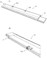
本発明による空気調和機は、図1(A)および図1(B)と、図2とに示すように、空気調和機本体1の吸込口2と吹出口5とを結ぶ空気通路に設けられた熱交換器3によって、吸込口2から吸い込まれた空気が冷媒と熱交換されたのち、送風ファン4によって吹出口5に送出され、吹出口5から被空調室に吹き出されるようになっている。
The air conditioner according to the present invention is provided in an air passage connecting the
吹出口5は、上壁5aと下壁5bとに接続された複数の支柱6が設けられることで、熱交換器3によって冷媒と熱交換された温風あるいは冷風(調和空気)が流通する時の温度変化の影響で変形してしまわないように、強度が増強された構成になっている。
The
また、吹出口5には、回動軸部10aを備えた前部の上下風向板10が回動自在に設けられるとともに、回動軸部13aを備えた後部の上下風向板13が回動自在に設けられることで、調和空気が吹出口5を流通する時の上下方向の風向を広範囲に偏向できるようになっている。
In addition, the
支柱6は平板状に形成され、後部の上下風向板13に備えた回動軸部13aを回動自在に軸支する支軸孔12と、支軸孔12を備えた支軸片11とからなる支軸部を備えるとともに、回動軸部13aを支軸孔12に挿入する時の作業性を良好にするため、支軸部を板厚方向に容易に弾性変形させるための後述するスリット7を備えている。
The
本発明の実施例においては、吹出口5の一部をなす後部の上下風向板(ディフューザ)13が、その後端部に備えた回動軸部13aを、支軸孔12を備えた支軸片11からなる支柱6に備えた支軸部で容易に軸支することで回動自在とした構成について、以下に詳細に説明する。
In the embodiment of the present invention, the rear upper and lower wind direction plate (diffuser) 13 forming a part of the
なお、後部の上下風向板13に備えた回動軸部13aは、図4(A)および図4(B)に示すように、上下風向板13を回動させるための回動軸からなる構成であって、支柱6に備えた支持部は、回動軸からなる回動軸部13aに対応する支軸孔12と、この支軸孔12を備えた支軸片11とからなる構成として説明するが、この構成に限らず回動軸部13aの側に支軸孔を備え、この支軸孔に対応して支持部の側に回動軸を備えた構成であってもよい。
In addition, as shown in FIG. 4 (A) and FIG. 4 (B), the
また、前部の上下風向板10についても、回動軸部10aを所定の幅寸法で形成された支軸片8で容易に軸支できるようにすることで回動自在とした構成を、後部の上下風向板13と同様に説明する。
The front vertical
前部の上下風向板10は、吹出口5の上壁5aから垂下された支軸片8によって、吹出口5の前部上位における上下方向の風向を偏向できるように支持されており、後部の上下風向板13は、支柱6の前端下部から下方に延出された支軸片11によって、吹出口5の後部下位における上下方向の風向を偏向できるように支持されている。このとき、支軸片11は支柱6の前端上部と前端下部とを結ぶ仮想線より前方に延出している。
The front vertical
また、後部の上下風向板13は、上下方向の風向を広範囲に偏向する機能を有するとともに、吹出口5の下壁5bの延長上に連続させるように配置されることで、この下壁5bを延長できる構成部材を兼ねている。
The rear vertical
吹出口5の上壁5aから垂下された支軸片8は、前部の上下風向板10に備えた回動軸部10aを軸支する支軸孔9を先端に備えており、支柱6の前端下部から下方に延出された支軸片11は、後部の上下風向板13に備えた回動軸部13aを軸支する支軸孔12を先端に備えている。
The
前部の上下風向板10は、図1(A)に示すように、その両側部と吹出口5の両壁部とに備えた図示しない凹凸状の枢支部Aで回動自在に枢支されるとともに、長手方向の中間部に備えた複数の回動軸部10aが、この回動軸部10aに対応して吹出口5の上壁5aから垂下され、先端に支軸孔9を備えた支軸片8からなる支軸部によって回動自在に軸支されている。
As shown in FIG. 1 (A), the front vertical
前部の上下風向板10は、弾性変形させることによって長手方向が短寸法となるように撓ませることにより、凹凸状の枢支部Aの組立作業を容易に行うことができる。
By assembling the front and lower
なお、凹凸状の枢支部Aは、前部の上下風向板10の両側部に備えた凹状の支軸部または凸状の回動軸部と、これら凹状の支軸部または凸状の回動軸部に対応して、吹出口5の両壁部に備えた凸状の回動軸部または凹状の支軸部とで構成されている。
The concave and convex pivot support portion A includes a concave support shaft portion or a convex rotation shaft portion provided on both sides of the front vertical
前部の上下風向板10の両側部が枢支部Aで回動自在に枢支されたのち、前部の上下風向板10の中間部における複数の回動軸部10aが、支軸孔9を先端に備えた支軸片8からなる支軸部で軸支される際、支軸片8の先端を板厚方向に弾性変形させることで回動軸部10aを支軸孔9に容易に挿入できるため、前部の上下風向板10の回動軸部10aを支軸部で軸支する時の作業性が良好になる。
After both sides of the front vertical
後部の上下風向板13は、図1(A)に示すように、その両側部と吹出口5の両壁部とに備えた図示しない凹凸状の枢支部Bで回動自在に枢支されるとともに、図3(A)および図3(B)に示す長手方向の中間部に備えた複数の回動軸部13aが、図2(A)乃至図2(C)に示すように、この回動軸部13aに対応して、支柱6の前端下部から下方に延出され支軸孔12を先端に備えた支軸片11からなる支軸部によって回動自在に軸支されている。
As shown in FIG. 1 (A), the rear vertical
後部の上下風向板13は、弾性変形させることによって長手方向が短寸法となるように撓ませることにより、凹凸状の枢支部Bの組立作業を容易に行うことができる。
The rear up-and-down
なお、凹凸状の枢支部Bは、後部の上下風向板13の両側部に備えた凹状の支軸部または凸状の回動軸部と、これら凹状の支軸部または凸状の回動軸部に対応して、吹出口5の両壁部に備えた凸状の回動軸部または凹状の支軸部とで構成されている。
The concave and convex pivot support B includes a concave support shaft portion or a convex rotation shaft portion provided on both sides of the rear vertical
支柱6は、支軸片11が板厚方向に弾性変形できるように開放端を有するスリット7を備えた構成になっており、このスリット7は、図2(A)乃至図2(C)に示すように、支軸片11の後部に、下端部を開放して支柱6の上方に延びるように形成されている。このとき、スリット7は開放端から支柱6の前端上部と前端下部とを結ぶ仮想線より後方に延出している。
The
なお、スリット7は、下端部を開放して支軸片11の後部に支柱6の上方に延びるように形成された構成に限らず、例えば図3(A)に示すように、スリット7が支持孔12の両側部から支柱6の後端部に向けて延びるように形成されることで、支軸片11が板厚方向に弾性変形できる形状に形成された構成にしてもよい。
The
または、例えば図3(B)に示すように、スリット7が支持孔12の一側部から支柱6の後端部に向けて延びるように形成されることで、支軸片11が板厚方向に弾性変形できる形状に形成された構成にしてもよい。
Alternatively, for example, as shown in FIG. 3B, the
後部の上下風向板13の両側部が枢支部Bで回動自在に枢支されたのち、後部の上下風向板13の中間部における複数の回動軸部13aが支軸片11に備えた支軸孔12で軸支される際、支柱6にスリット7が形成されたことにより、支軸孔12を備えた支軸片11の先端を板厚方向に弾性変形させることで回動軸部13aを容易に支軸孔12に挿入できるようになるため、後部の上下風向板13の後端部に備えた回動軸部13aを支軸孔12に組み付ける時の作業性が良好になる。
After both side portions of the rear vertical
以上説明したように、本発明は、吸込口2と吹出口5とを備え、吹出口5の上壁5aと下壁5bとの間に支柱6を備え、支柱6に備えた支軸部により後部の上下風向板13の回動軸部13aが回動自在に軸支された空気調和機において、回動軸部13aが後部の上下風向板13の後端部に設けられるとともに、支軸部が支柱6の前端下部から下方に延出されて先端に支軸孔12を備えた支軸片11からなり、支軸片11の後部に、下端部を開放して支柱6の上方に延びるスリット7が形成された構成にしている。
As described above, the present invention includes the
更に、スリット7が支軸片11および支柱6の前端部と平行に形成されたことで、支軸片11を支軸片8と同様に所定の幅寸法と所定の長さ寸法とを有した形状に形成できることから、回動軸部13aが後部の上下風向板13の後端部に設けられて、支軸片11に備えた支軸孔12と、支柱6との間隔が近い構成になったとしても、支軸片11を所定の力で板厚方向に弾性変形させることを可能にした構成にしている。
Further, since the
本発明の構成によれば、吹出口5の上壁5aと下壁5bとの間に支柱6を備え、この支柱6に備えた支軸片11からなる支軸部を板厚方向に弾性変形させることができるようにしたことで、後部の上下風向板13の後端部に備えた回動軸部13aを支軸片11に備えた支軸孔12に容易に挿入できるようにして、後部の上下風向板13の回動軸部13aを支軸部に組み付ける時の作業性を良好にした空気調和機を提供できる。
According to the configuration of the present invention, the
1 空気調和機
2 吸込口
3 熱交換器
4 送風ファン
5 吹出口
5a 上壁
5b 下壁
6 支柱
7 スリット
8 支軸片
9 支軸孔
10 前部の上下風向板
10a 回動軸部
11 支軸片
12 支軸孔
13 後部の上下風向板
13a 回動軸部
A,B 枢支部
DESCRIPTION OF
Claims (1)
前記回動軸部が、前記上下風向板の後端部に設けられ、
前記支軸部は、前記下壁の前端に隣接し、且つ、前記上下風向板が前記下壁の延長上に連続的に配置されるように前記回動軸部を軸支できる位置に備えられ、
前記支軸部の後部に、下端部を開放して前記支柱の上方に延びるスリットが形成されており、
前記スリットが、前記支軸部および前記支柱の前端部と平行に形成されてなることを特徴とする空気調和機。
Equipped with a suction port and air outlet, with a plate-like column between the upper and lower walls of the air outlet, and the pivot shaft part of the vertical wind direction plate is rotatable by the support shaft part provided on the column In the air conditioner pivotally supported by
The pivot shaft is provided at a rear end of the up-and-down wind direction plate;
The support shaft is adjacent to the front end of the lower wall, and is provided at a position where the pivot shaft can be supported so that the up-and-down wind direction plate is continuously disposed on the extension of the lower wall. ,
In the rear part of the support shaft part, a slit is formed that opens the lower end and extends above the support column.
The air conditioner characterized in that the slit is formed in parallel with the support shaft portion and the front end portion of the support column .
Priority Applications (1)
| Application Number | Priority Date | Filing Date | Title |
|---|---|---|---|
| JP2010289259A JP5728935B2 (en) | 2010-12-27 | 2010-12-27 | Air conditioner |
Applications Claiming Priority (1)
| Application Number | Priority Date | Filing Date | Title |
|---|---|---|---|
| JP2010289259A JP5728935B2 (en) | 2010-12-27 | 2010-12-27 | Air conditioner |
Publications (3)
| Publication Number | Publication Date |
|---|---|
| JP2012137227A JP2012137227A (en) | 2012-07-19 |
| JP2012137227A5 JP2012137227A5 (en) | 2014-01-30 |
| JP5728935B2 true JP5728935B2 (en) | 2015-06-03 |
Family
ID=46674784
Family Applications (1)
| Application Number | Title | Priority Date | Filing Date |
|---|---|---|---|
| JP2010289259A Active JP5728935B2 (en) | 2010-12-27 | 2010-12-27 | Air conditioner |
Country Status (1)
| Country | Link |
|---|---|
| JP (1) | JP5728935B2 (en) |
Families Citing this family (3)
| Publication number | Priority date | Publication date | Assignee | Title |
|---|---|---|---|---|
| KR100685914B1 (en) * | 2000-09-05 | 2007-02-23 | 엘지.필립스 엘시디 주식회사 | Multi-domain liquid crystal display device and manufacturing method thereof |
| JP2017044432A (en) * | 2015-08-28 | 2017-03-02 | ジョンソンコントロールズ ヒタチ エア コンディショニング テクノロジー(ホンコン)リミテッド | Air conditioner |
| CN106152451B (en) * | 2016-08-26 | 2021-10-15 | 珠海格力电器股份有限公司 | Shaft hole matching structure capable of rotating relatively, wind sweeping mechanism and air conditioner |
Family Cites Families (6)
| Publication number | Priority date | Publication date | Assignee | Title |
|---|---|---|---|---|
| US4009648A (en) * | 1975-10-03 | 1977-03-01 | General Motors Corporation | Air conditioner air flow control mechanism |
| JPS60138144U (en) * | 1984-02-27 | 1985-09-12 | トヨタ自動車株式会社 | Register locking structure |
| KR0126751Y1 (en) * | 1994-08-11 | 1998-11-02 | 윤종용 | Wind direction control device |
| JP3171786B2 (en) * | 1996-06-26 | 2001-06-04 | 東芝キヤリア株式会社 | Air conditioner indoor unit |
| JP4915351B2 (en) * | 2008-01-17 | 2012-04-11 | 株式会社富士通ゼネラル | Air conditioner |
| JP2010223453A (en) * | 2009-03-19 | 2010-10-07 | Fujitsu General Ltd | Air conditioner |
-
2010
- 2010-12-27 JP JP2010289259A patent/JP5728935B2/en active Active
Also Published As
| Publication number | Publication date |
|---|---|
| JP2012137227A (en) | 2012-07-19 |
Similar Documents
| Publication | Publication Date | Title |
|---|---|---|
| JP5817391B2 (en) | Air conditioner | |
| CN107036162B (en) | Wall-mounted air conditioner with air outlets at two sides | |
| JP5383628B2 (en) | Air conditioner | |
| JP5728935B2 (en) | Air conditioner | |
| JP6078925B2 (en) | Embedded ceiling air conditioner | |
| JP4513548B2 (en) | Air conditioner indoor unit | |
| JP2010065876A (en) | Air conditioner | |
| CN110864354A (en) | Grid panel, embedded air outlet panel component and air duct machine | |
| JP6114045B2 (en) | Wind direction changing device and air conditioner having the same | |
| JP6264347B2 (en) | Air conditioning indoor unit | |
| JP2010065877A (en) | Air conditioner | |
| JP5796313B2 (en) | Wind direction changing device and air conditioner equipped with the same | |
| JP2013148227A (en) | Airflow direction changing device, and air conditioning device provided with the same | |
| JP5359727B2 (en) | Air conditioner indoor unit | |
| JP2005315538A (en) | Air conditioner | |
| JP2010091260A (en) | Air conditioner | |
| JP2008128572A5 (en) | ||
| JP2011147685A (en) | Blower | |
| WO2012172727A1 (en) | Air conditioner | |
| JP6070734B2 (en) | Air conditioning indoor unit | |
| WO2021169803A1 (en) | Wall-mounted air conditioner indoor unit and air deflector thereof | |
| JP2015087061A (en) | Air conditioner | |
| JP2014122750A (en) | Air conditioner | |
| JP2008002781A (en) | Air conditioner | |
| KR100251812B1 (en) | Indoor unit of airconditioner |
Legal Events
| Date | Code | Title | Description |
|---|---|---|---|
| A521 | Written amendment |
Free format text: JAPANESE INTERMEDIATE CODE: A523 Effective date: 20131209 |
|
| A621 | Written request for application examination |
Free format text: JAPANESE INTERMEDIATE CODE: A621 Effective date: 20131226 |
|
| A977 | Report on retrieval |
Free format text: JAPANESE INTERMEDIATE CODE: A971007 Effective date: 20140620 |
|
| A131 | Notification of reasons for refusal |
Free format text: JAPANESE INTERMEDIATE CODE: A131 Effective date: 20140701 |
|
| A521 | Written amendment |
Free format text: JAPANESE INTERMEDIATE CODE: A523 Effective date: 20140901 |
|
| TRDD | Decision of grant or rejection written | ||
| A01 | Written decision to grant a patent or to grant a registration (utility model) |
Free format text: JAPANESE INTERMEDIATE CODE: A01 Effective date: 20150310 |
|
| A61 | First payment of annual fees (during grant procedure) |
Free format text: JAPANESE INTERMEDIATE CODE: A61 Effective date: 20150323 |
|
| R151 | Written notification of patent or utility model registration |
Ref document number: 5728935 Country of ref document: JP Free format text: JAPANESE INTERMEDIATE CODE: R151 |