JP5719377B2 - Reticulated cordierite composition, article and production thereof - Google Patents
Reticulated cordierite composition, article and production thereof Download PDFInfo
- Publication number
- JP5719377B2 JP5719377B2 JP2012542107A JP2012542107A JP5719377B2 JP 5719377 B2 JP5719377 B2 JP 5719377B2 JP 2012542107 A JP2012542107 A JP 2012542107A JP 2012542107 A JP2012542107 A JP 2012542107A JP 5719377 B2 JP5719377 B2 JP 5719377B2
- Authority
- JP
- Japan
- Prior art keywords
- cordierite
- batch
- elongated particles
- certain embodiments
- porosity
- Prior art date
- Legal status (The legal status is an assumption and is not a legal conclusion. Google has not performed a legal analysis and makes no representation as to the accuracy of the status listed.)
- Expired - Fee Related
Links
- 229910052878 cordierite Inorganic materials 0.000 title claims description 98
- JSKIRARMQDRGJZ-UHFFFAOYSA-N dimagnesium dioxido-bis[(1-oxido-3-oxo-2,4,6,8,9-pentaoxa-1,3-disila-5,7-dialuminabicyclo[3.3.1]nonan-7-yl)oxy]silane Chemical compound [Mg++].[Mg++].[O-][Si]([O-])(O[Al]1O[Al]2O[Si](=O)O[Si]([O-])(O1)O2)O[Al]1O[Al]2O[Si](=O)O[Si]([O-])(O1)O2 JSKIRARMQDRGJZ-UHFFFAOYSA-N 0.000 title claims description 98
- 239000000203 mixture Substances 0.000 title description 46
- 229910010293 ceramic material Inorganic materials 0.000 claims description 26
- 210000004027 cell Anatomy 0.000 claims description 14
- QSHDDOUJBYECFT-UHFFFAOYSA-N mercury Chemical compound [Hg] QSHDDOUJBYECFT-UHFFFAOYSA-N 0.000 claims description 13
- 229910052753 mercury Inorganic materials 0.000 claims description 13
- 238000002459 porosimetry Methods 0.000 claims description 7
- 238000012360 testing method Methods 0.000 claims description 7
- 238000013001 point bending Methods 0.000 claims description 5
- 210000002421 cell wall Anatomy 0.000 claims description 4
- 239000011159 matrix material Substances 0.000 claims description 4
- 230000001747 exhibiting effect Effects 0.000 claims 1
- 239000002245 particle Substances 0.000 description 128
- PNEYBMLMFCGWSK-UHFFFAOYSA-N aluminium oxide Inorganic materials [O-2].[O-2].[O-2].[Al+3].[Al+3] PNEYBMLMFCGWSK-UHFFFAOYSA-N 0.000 description 50
- 239000011148 porous material Substances 0.000 description 47
- 239000000463 material Substances 0.000 description 46
- 239000000919 ceramic Substances 0.000 description 37
- 238000010438 heat treatment Methods 0.000 description 28
- 239000000454 talc Substances 0.000 description 26
- 229910052623 talc Inorganic materials 0.000 description 26
- VYPSYNLAJGMNEJ-UHFFFAOYSA-N Silicium dioxide Chemical compound O=[Si]=O VYPSYNLAJGMNEJ-UHFFFAOYSA-N 0.000 description 23
- 238000001816 cooling Methods 0.000 description 23
- 229910000323 aluminium silicate Inorganic materials 0.000 description 22
- HNPSIPDUKPIQMN-UHFFFAOYSA-N dioxosilane;oxo(oxoalumanyloxy)alumane Chemical compound O=[Si]=O.O=[Al]O[Al]=O HNPSIPDUKPIQMN-UHFFFAOYSA-N 0.000 description 22
- 238000001125 extrusion Methods 0.000 description 21
- 238000009826 distribution Methods 0.000 description 16
- 239000002994 raw material Substances 0.000 description 15
- 239000004927 clay Substances 0.000 description 14
- 229910052570 clay Inorganic materials 0.000 description 14
- 239000013078 crystal Substances 0.000 description 13
- 238000001878 scanning electron micrograph Methods 0.000 description 13
- 238000000034 method Methods 0.000 description 12
- 239000000377 silicon dioxide Substances 0.000 description 11
- CPLXHLVBOLITMK-UHFFFAOYSA-N Magnesium oxide Chemical compound [Mg]=O CPLXHLVBOLITMK-UHFFFAOYSA-N 0.000 description 10
- 230000000052 comparative effect Effects 0.000 description 10
- 239000011521 glass Substances 0.000 description 10
- 229920002261 Corn starch Polymers 0.000 description 9
- 239000008120 corn starch Substances 0.000 description 9
- 229920001592 potato starch Polymers 0.000 description 9
- 238000010304 firing Methods 0.000 description 8
- 230000015572 biosynthetic process Effects 0.000 description 7
- 238000001887 electron backscatter diffraction Methods 0.000 description 7
- 239000011230 binding agent Substances 0.000 description 6
- 230000035939 shock Effects 0.000 description 6
- KZHJGOXRZJKJNY-UHFFFAOYSA-N dioxosilane;oxo(oxoalumanyloxy)alumane Chemical compound O=[Si]=O.O=[Si]=O.O=[Al]O[Al]=O.O=[Al]O[Al]=O.O=[Al]O[Al]=O KZHJGOXRZJKJNY-UHFFFAOYSA-N 0.000 description 5
- 239000000395 magnesium oxide Substances 0.000 description 5
- 229910052863 mullite Inorganic materials 0.000 description 5
- 238000006243 chemical reaction Methods 0.000 description 4
- 238000013507 mapping Methods 0.000 description 4
- 238000002156 mixing Methods 0.000 description 4
- 239000002243 precursor Substances 0.000 description 4
- 238000004458 analytical method Methods 0.000 description 3
- 230000001186 cumulative effect Effects 0.000 description 3
- 230000007423 decrease Effects 0.000 description 3
- 239000000835 fiber Substances 0.000 description 3
- 239000007789 gas Substances 0.000 description 3
- 238000005259 measurement Methods 0.000 description 3
- 238000012545 processing Methods 0.000 description 3
- 239000000126 substance Substances 0.000 description 3
- XLYOFNOQVPJJNP-UHFFFAOYSA-N water Substances O XLYOFNOQVPJJNP-UHFFFAOYSA-N 0.000 description 3
- 239000004593 Epoxy Substances 0.000 description 2
- 238000002441 X-ray diffraction Methods 0.000 description 2
- 239000003125 aqueous solvent Substances 0.000 description 2
- 239000003054 catalyst Substances 0.000 description 2
- 239000003795 chemical substances by application Substances 0.000 description 2
- 238000013480 data collection Methods 0.000 description 2
- 230000003247 decreasing effect Effects 0.000 description 2
- 238000010894 electron beam technology Methods 0.000 description 2
- 238000002003 electron diffraction Methods 0.000 description 2
- 239000010419 fine particle Substances 0.000 description 2
- 238000000227 grinding Methods 0.000 description 2
- 239000004615 ingredient Substances 0.000 description 2
- 238000001000 micrograph Methods 0.000 description 2
- 230000035699 permeability Effects 0.000 description 2
- 238000005498 polishing Methods 0.000 description 2
- 230000009467 reduction Effects 0.000 description 2
- 229910052596 spinel Inorganic materials 0.000 description 2
- 239000011029 spinel Substances 0.000 description 2
- 238000005382 thermal cycling Methods 0.000 description 2
- RPZANUYHRMRTTE-UHFFFAOYSA-N 2,3,4-trimethoxy-6-(methoxymethyl)-5-[3,4,5-trimethoxy-6-(methoxymethyl)oxan-2-yl]oxyoxane;1-[[3,4,5-tris(2-hydroxybutoxy)-6-[4,5,6-tris(2-hydroxybutoxy)-2-(2-hydroxybutoxymethyl)oxan-3-yl]oxyoxan-2-yl]methoxy]butan-2-ol Chemical compound COC1C(OC)C(OC)C(COC)OC1OC1C(OC)C(OC)C(OC)OC1COC.CCC(O)COC1C(OCC(O)CC)C(OCC(O)CC)C(COCC(O)CC)OC1OC1C(OCC(O)CC)C(OCC(O)CC)C(OCC(O)CC)OC1COCC(O)CC RPZANUYHRMRTTE-UHFFFAOYSA-N 0.000 description 1
- 239000005995 Aluminium silicate Substances 0.000 description 1
- OKTJSMMVPCPJKN-UHFFFAOYSA-N Carbon Chemical compound [C] OKTJSMMVPCPJKN-UHFFFAOYSA-N 0.000 description 1
- 229920000896 Ethulose Polymers 0.000 description 1
- 239000001859 Ethyl hydroxyethyl cellulose Substances 0.000 description 1
- 229920000663 Hydroxyethyl cellulose Polymers 0.000 description 1
- 239000004354 Hydroxyethyl cellulose Substances 0.000 description 1
- 229920001479 Hydroxyethyl methyl cellulose Polymers 0.000 description 1
- 229920002153 Hydroxypropyl cellulose Polymers 0.000 description 1
- MXRIRQGCELJRSN-UHFFFAOYSA-N O.O.O.[Al] Chemical compound O.O.O.[Al] MXRIRQGCELJRSN-UHFFFAOYSA-N 0.000 description 1
- OAICVXFJPJFONN-UHFFFAOYSA-N Phosphorus Chemical compound [P] OAICVXFJPJFONN-UHFFFAOYSA-N 0.000 description 1
- 239000004793 Polystyrene Substances 0.000 description 1
- 238000003991 Rietveld refinement Methods 0.000 description 1
- 229920002472 Starch Polymers 0.000 description 1
- 230000001133 acceleration Effects 0.000 description 1
- DPXJVFZANSGRMM-UHFFFAOYSA-N acetic acid;2,3,4,5,6-pentahydroxyhexanal;sodium Chemical compound [Na].CC(O)=O.OCC(O)C(O)C(O)C(O)C=O DPXJVFZANSGRMM-UHFFFAOYSA-N 0.000 description 1
- 239000000654 additive Substances 0.000 description 1
- 230000000996 additive effect Effects 0.000 description 1
- 238000007605 air drying Methods 0.000 description 1
- 235000012211 aluminium silicate Nutrition 0.000 description 1
- 238000002048 anodisation reaction Methods 0.000 description 1
- 239000011324 bead Substances 0.000 description 1
- 238000005452 bending Methods 0.000 description 1
- 230000009286 beneficial effect Effects 0.000 description 1
- 230000008901 benefit Effects 0.000 description 1
- 239000001768 carboxy methyl cellulose Substances 0.000 description 1
- 239000000969 carrier Substances 0.000 description 1
- 230000001413 cellular effect Effects 0.000 description 1
- 210000003850 cellular structure Anatomy 0.000 description 1
- 229920003086 cellulose ether Polymers 0.000 description 1
- 238000012512 characterization method Methods 0.000 description 1
- 239000007795 chemical reaction product Substances 0.000 description 1
- 239000011248 coating agent Substances 0.000 description 1
- 238000000576 coating method Methods 0.000 description 1
- 239000008119 colloidal silica Substances 0.000 description 1
- 238000010586 diagram Methods 0.000 description 1
- 238000001035 drying Methods 0.000 description 1
- 238000003487 electrochemical reaction Methods 0.000 description 1
- 238000002149 energy-dispersive X-ray emission spectroscopy Methods 0.000 description 1
- 235000019326 ethyl hydroxyethyl cellulose Nutrition 0.000 description 1
- 239000002657 fibrous material Substances 0.000 description 1
- 238000001914 filtration Methods 0.000 description 1
- 230000009969 flowable effect Effects 0.000 description 1
- 239000012530 fluid Substances 0.000 description 1
- 238000009472 formulation Methods 0.000 description 1
- 239000012634 fragment Substances 0.000 description 1
- 239000010439 graphite Substances 0.000 description 1
- 229910002804 graphite Inorganic materials 0.000 description 1
- 238000009499 grossing Methods 0.000 description 1
- 238000001198 high resolution scanning electron microscopy Methods 0.000 description 1
- 125000002887 hydroxy group Chemical group [H]O* 0.000 description 1
- 235000019447 hydroxyethyl cellulose Nutrition 0.000 description 1
- 229920003063 hydroxymethyl cellulose Polymers 0.000 description 1
- 229940031574 hydroxymethyl cellulose Drugs 0.000 description 1
- 239000001863 hydroxypropyl cellulose Substances 0.000 description 1
- 235000010977 hydroxypropyl cellulose Nutrition 0.000 description 1
- 230000006872 improvement Effects 0.000 description 1
- 229910010272 inorganic material Inorganic materials 0.000 description 1
- 239000011147 inorganic material Substances 0.000 description 1
- 239000013067 intermediate product Substances 0.000 description 1
- 229910052741 iridium Inorganic materials 0.000 description 1
- GKOZUEZYRPOHIO-UHFFFAOYSA-N iridium atom Chemical compound [Ir] GKOZUEZYRPOHIO-UHFFFAOYSA-N 0.000 description 1
- NLYAJNPCOHFWQQ-UHFFFAOYSA-N kaolin Chemical compound O.O.O=[Al]O[Si](=O)O[Si](=O)O[Al]=O NLYAJNPCOHFWQQ-UHFFFAOYSA-N 0.000 description 1
- 239000007788 liquid Substances 0.000 description 1
- 238000011068 loading method Methods 0.000 description 1
- 239000000314 lubricant Substances 0.000 description 1
- 229920000609 methyl cellulose Polymers 0.000 description 1
- 239000001923 methylcellulose Substances 0.000 description 1
- 239000011859 microparticle Substances 0.000 description 1
- 239000011236 particulate material Substances 0.000 description 1
- 239000004014 plasticizer Substances 0.000 description 1
- 229920002223 polystyrene Polymers 0.000 description 1
- 239000000843 powder Substances 0.000 description 1
- 230000008569 process Effects 0.000 description 1
- 239000000047 product Substances 0.000 description 1
- 238000011002 quantification Methods 0.000 description 1
- 239000012925 reference material Substances 0.000 description 1
- 230000004044 response Effects 0.000 description 1
- 238000000926 separation method Methods 0.000 description 1
- 235000019812 sodium carboxymethyl cellulose Nutrition 0.000 description 1
- 229920001027 sodium carboxymethylcellulose Polymers 0.000 description 1
- 239000007787 solid Substances 0.000 description 1
- 239000002904 solvent Substances 0.000 description 1
- 239000004071 soot Substances 0.000 description 1
- 239000012798 spherical particle Substances 0.000 description 1
- 239000008107 starch Substances 0.000 description 1
- 235000019698 starch Nutrition 0.000 description 1
- 239000000758 substrate Substances 0.000 description 1
- 238000010998 test method Methods 0.000 description 1
- 238000011144 upstream manufacturing Methods 0.000 description 1
- 238000009736 wetting Methods 0.000 description 1
Images


Classifications
-
- B—PERFORMING OPERATIONS; TRANSPORTING
- B01—PHYSICAL OR CHEMICAL PROCESSES OR APPARATUS IN GENERAL
- B01D—SEPARATION
- B01D46/00—Filters or filtering processes specially modified for separating dispersed particles from gases or vapours
- B01D46/24—Particle separators, e.g. dust precipitators, using rigid hollow filter bodies
- B01D46/2403—Particle separators, e.g. dust precipitators, using rigid hollow filter bodies characterised by the physical shape or structure of the filtering element
- B01D46/2418—Honeycomb filters
- B01D46/2451—Honeycomb filters characterized by the geometrical structure, shape, pattern or configuration or parameters related to the geometry of the structure
- B01D46/2474—Honeycomb filters characterized by the geometrical structure, shape, pattern or configuration or parameters related to the geometry of the structure of the walls along the length of the honeycomb
-
- B—PERFORMING OPERATIONS; TRANSPORTING
- B01—PHYSICAL OR CHEMICAL PROCESSES OR APPARATUS IN GENERAL
- B01D—SEPARATION
- B01D46/00—Filters or filtering processes specially modified for separating dispersed particles from gases or vapours
- B01D46/24—Particle separators, e.g. dust precipitators, using rigid hollow filter bodies
- B01D46/2403—Particle separators, e.g. dust precipitators, using rigid hollow filter bodies characterised by the physical shape or structure of the filtering element
- B01D46/2418—Honeycomb filters
- B01D46/2425—Honeycomb filters characterized by parameters related to the physical properties of the honeycomb structure material
- B01D46/2429—Honeycomb filters characterized by parameters related to the physical properties of the honeycomb structure material of the honeycomb walls or cells
-
- B—PERFORMING OPERATIONS; TRANSPORTING
- B01—PHYSICAL OR CHEMICAL PROCESSES OR APPARATUS IN GENERAL
- B01D—SEPARATION
- B01D46/00—Filters or filtering processes specially modified for separating dispersed particles from gases or vapours
- B01D46/24—Particle separators, e.g. dust precipitators, using rigid hollow filter bodies
- B01D46/2403—Particle separators, e.g. dust precipitators, using rigid hollow filter bodies characterised by the physical shape or structure of the filtering element
- B01D46/2418—Honeycomb filters
- B01D46/2425—Honeycomb filters characterized by parameters related to the physical properties of the honeycomb structure material
- B01D46/24491—Porosity
-
- B—PERFORMING OPERATIONS; TRANSPORTING
- B01—PHYSICAL OR CHEMICAL PROCESSES OR APPARATUS IN GENERAL
- B01D—SEPARATION
- B01D46/00—Filters or filtering processes specially modified for separating dispersed particles from gases or vapours
- B01D46/24—Particle separators, e.g. dust precipitators, using rigid hollow filter bodies
- B01D46/2403—Particle separators, e.g. dust precipitators, using rigid hollow filter bodies characterised by the physical shape or structure of the filtering element
- B01D46/2418—Honeycomb filters
- B01D46/2425—Honeycomb filters characterized by parameters related to the physical properties of the honeycomb structure material
- B01D46/24492—Pore diameter
-
- B—PERFORMING OPERATIONS; TRANSPORTING
- B01—PHYSICAL OR CHEMICAL PROCESSES OR APPARATUS IN GENERAL
- B01D—SEPARATION
- B01D46/00—Filters or filtering processes specially modified for separating dispersed particles from gases or vapours
- B01D46/24—Particle separators, e.g. dust precipitators, using rigid hollow filter bodies
- B01D46/2403—Particle separators, e.g. dust precipitators, using rigid hollow filter bodies characterised by the physical shape or structure of the filtering element
- B01D46/2418—Honeycomb filters
- B01D46/2425—Honeycomb filters characterized by parameters related to the physical properties of the honeycomb structure material
- B01D46/24493—Modulus of rupture
-
- B—PERFORMING OPERATIONS; TRANSPORTING
- B01—PHYSICAL OR CHEMICAL PROCESSES OR APPARATUS IN GENERAL
- B01D—SEPARATION
- B01D46/00—Filters or filtering processes specially modified for separating dispersed particles from gases or vapours
- B01D46/24—Particle separators, e.g. dust precipitators, using rigid hollow filter bodies
- B01D46/2403—Particle separators, e.g. dust precipitators, using rigid hollow filter bodies characterised by the physical shape or structure of the filtering element
- B01D46/2418—Honeycomb filters
- B01D46/2425—Honeycomb filters characterized by parameters related to the physical properties of the honeycomb structure material
- B01D46/24494—Thermal expansion coefficient, heat capacity or thermal conductivity
-
- B—PERFORMING OPERATIONS; TRANSPORTING
- B01—PHYSICAL OR CHEMICAL PROCESSES OR APPARATUS IN GENERAL
- B01D—SEPARATION
- B01D46/00—Filters or filtering processes specially modified for separating dispersed particles from gases or vapours
- B01D46/24—Particle separators, e.g. dust precipitators, using rigid hollow filter bodies
- B01D46/2403—Particle separators, e.g. dust precipitators, using rigid hollow filter bodies characterised by the physical shape or structure of the filtering element
- B01D46/2418—Honeycomb filters
- B01D46/2451—Honeycomb filters characterized by the geometrical structure, shape, pattern or configuration or parameters related to the geometry of the structure
- B01D46/247—Honeycomb filters characterized by the geometrical structure, shape, pattern or configuration or parameters related to the geometry of the structure of the cells
-
- B—PERFORMING OPERATIONS; TRANSPORTING
- B01—PHYSICAL OR CHEMICAL PROCESSES OR APPARATUS IN GENERAL
- B01D—SEPARATION
- B01D46/00—Filters or filtering processes specially modified for separating dispersed particles from gases or vapours
- B01D46/24—Particle separators, e.g. dust precipitators, using rigid hollow filter bodies
- B01D46/2403—Particle separators, e.g. dust precipitators, using rigid hollow filter bodies characterised by the physical shape or structure of the filtering element
- B01D46/2418—Honeycomb filters
- B01D46/2451—Honeycomb filters characterized by the geometrical structure, shape, pattern or configuration or parameters related to the geometry of the structure
- B01D46/2482—Thickness, height, width, length or diameter
-
- B—PERFORMING OPERATIONS; TRANSPORTING
- B01—PHYSICAL OR CHEMICAL PROCESSES OR APPARATUS IN GENERAL
- B01D—SEPARATION
- B01D46/00—Filters or filtering processes specially modified for separating dispersed particles from gases or vapours
- B01D46/24—Particle separators, e.g. dust precipitators, using rigid hollow filter bodies
- B01D46/2403—Particle separators, e.g. dust precipitators, using rigid hollow filter bodies characterised by the physical shape or structure of the filtering element
- B01D46/2418—Honeycomb filters
- B01D46/2451—Honeycomb filters characterized by the geometrical structure, shape, pattern or configuration or parameters related to the geometry of the structure
- B01D46/2484—Cell density, area or aspect ratio
-
- C—CHEMISTRY; METALLURGY
- C04—CEMENTS; CONCRETE; ARTIFICIAL STONE; CERAMICS; REFRACTORIES
- C04B—LIME, MAGNESIA; SLAG; CEMENTS; COMPOSITIONS THEREOF, e.g. MORTARS, CONCRETE OR LIKE BUILDING MATERIALS; ARTIFICIAL STONE; CERAMICS; REFRACTORIES; TREATMENT OF NATURAL STONE
- C04B35/00—Shaped ceramic products characterised by their composition; Ceramics compositions; Processing powders of inorganic compounds preparatory to the manufacturing of ceramic products
- C04B35/01—Shaped ceramic products characterised by their composition; Ceramics compositions; Processing powders of inorganic compounds preparatory to the manufacturing of ceramic products based on oxide ceramics
- C04B35/16—Shaped ceramic products characterised by their composition; Ceramics compositions; Processing powders of inorganic compounds preparatory to the manufacturing of ceramic products based on oxide ceramics based on silicates other than clay
- C04B35/18—Shaped ceramic products characterised by their composition; Ceramics compositions; Processing powders of inorganic compounds preparatory to the manufacturing of ceramic products based on oxide ceramics based on silicates other than clay rich in aluminium oxide
- C04B35/195—Alkaline earth aluminosilicates, e.g. cordierite or anorthite
-
- C—CHEMISTRY; METALLURGY
- C04—CEMENTS; CONCRETE; ARTIFICIAL STONE; CERAMICS; REFRACTORIES
- C04B—LIME, MAGNESIA; SLAG; CEMENTS; COMPOSITIONS THEREOF, e.g. MORTARS, CONCRETE OR LIKE BUILDING MATERIALS; ARTIFICIAL STONE; CERAMICS; REFRACTORIES; TREATMENT OF NATURAL STONE
- C04B38/00—Porous mortars, concrete, artificial stone or ceramic ware; Preparation thereof
- C04B38/0006—Honeycomb structures
-
- B—PERFORMING OPERATIONS; TRANSPORTING
- B01—PHYSICAL OR CHEMICAL PROCESSES OR APPARATUS IN GENERAL
- B01D—SEPARATION
- B01D46/00—Filters or filtering processes specially modified for separating dispersed particles from gases or vapours
- B01D46/24—Particle separators, e.g. dust precipitators, using rigid hollow filter bodies
- B01D46/2403—Particle separators, e.g. dust precipitators, using rigid hollow filter bodies characterised by the physical shape or structure of the filtering element
- B01D46/2418—Honeycomb filters
- B01D46/2498—The honeycomb filter being defined by mathematical relationships
-
- C—CHEMISTRY; METALLURGY
- C04—CEMENTS; CONCRETE; ARTIFICIAL STONE; CERAMICS; REFRACTORIES
- C04B—LIME, MAGNESIA; SLAG; CEMENTS; COMPOSITIONS THEREOF, e.g. MORTARS, CONCRETE OR LIKE BUILDING MATERIALS; ARTIFICIAL STONE; CERAMICS; REFRACTORIES; TREATMENT OF NATURAL STONE
- C04B2111/00—Mortars, concrete or artificial stone or mixtures to prepare them, characterised by specific function, property or use
- C04B2111/00474—Uses not provided for elsewhere in C04B2111/00
- C04B2111/00793—Uses not provided for elsewhere in C04B2111/00 as filters or diaphragms
-
- C—CHEMISTRY; METALLURGY
- C04—CEMENTS; CONCRETE; ARTIFICIAL STONE; CERAMICS; REFRACTORIES
- C04B—LIME, MAGNESIA; SLAG; CEMENTS; COMPOSITIONS THEREOF, e.g. MORTARS, CONCRETE OR LIKE BUILDING MATERIALS; ARTIFICIAL STONE; CERAMICS; REFRACTORIES; TREATMENT OF NATURAL STONE
- C04B2111/00—Mortars, concrete or artificial stone or mixtures to prepare them, characterised by specific function, property or use
- C04B2111/00474—Uses not provided for elsewhere in C04B2111/00
- C04B2111/0081—Uses not provided for elsewhere in C04B2111/00 as catalysts or catalyst carriers
-
- C—CHEMISTRY; METALLURGY
- C04—CEMENTS; CONCRETE; ARTIFICIAL STONE; CERAMICS; REFRACTORIES
- C04B—LIME, MAGNESIA; SLAG; CEMENTS; COMPOSITIONS THEREOF, e.g. MORTARS, CONCRETE OR LIKE BUILDING MATERIALS; ARTIFICIAL STONE; CERAMICS; REFRACTORIES; TREATMENT OF NATURAL STONE
- C04B2235/00—Aspects relating to ceramic starting mixtures or sintered ceramic products
- C04B2235/02—Composition of constituents of the starting material or of secondary phases of the final product
- C04B2235/30—Constituents and secondary phases not being of a fibrous nature
- C04B2235/32—Metal oxides, mixed metal oxides, or oxide-forming salts thereof, e.g. carbonates, nitrates, (oxy)hydroxides, chlorides
- C04B2235/3205—Alkaline earth oxides or oxide forming salts thereof, e.g. beryllium oxide
- C04B2235/3206—Magnesium oxides or oxide-forming salts thereof
-
- C—CHEMISTRY; METALLURGY
- C04—CEMENTS; CONCRETE; ARTIFICIAL STONE; CERAMICS; REFRACTORIES
- C04B—LIME, MAGNESIA; SLAG; CEMENTS; COMPOSITIONS THEREOF, e.g. MORTARS, CONCRETE OR LIKE BUILDING MATERIALS; ARTIFICIAL STONE; CERAMICS; REFRACTORIES; TREATMENT OF NATURAL STONE
- C04B2235/00—Aspects relating to ceramic starting mixtures or sintered ceramic products
- C04B2235/02—Composition of constituents of the starting material or of secondary phases of the final product
- C04B2235/30—Constituents and secondary phases not being of a fibrous nature
- C04B2235/32—Metal oxides, mixed metal oxides, or oxide-forming salts thereof, e.g. carbonates, nitrates, (oxy)hydroxides, chlorides
- C04B2235/3217—Aluminum oxide or oxide forming salts thereof, e.g. bauxite, alpha-alumina
- C04B2235/3218—Aluminium (oxy)hydroxides, e.g. boehmite, gibbsite, alumina sol
-
- C—CHEMISTRY; METALLURGY
- C04—CEMENTS; CONCRETE; ARTIFICIAL STONE; CERAMICS; REFRACTORIES
- C04B—LIME, MAGNESIA; SLAG; CEMENTS; COMPOSITIONS THEREOF, e.g. MORTARS, CONCRETE OR LIKE BUILDING MATERIALS; ARTIFICIAL STONE; CERAMICS; REFRACTORIES; TREATMENT OF NATURAL STONE
- C04B2235/00—Aspects relating to ceramic starting mixtures or sintered ceramic products
- C04B2235/02—Composition of constituents of the starting material or of secondary phases of the final product
- C04B2235/30—Constituents and secondary phases not being of a fibrous nature
- C04B2235/34—Non-metal oxides, non-metal mixed oxides, or salts thereof that form the non-metal oxides upon heating, e.g. carbonates, nitrates, (oxy)hydroxides, chlorides
- C04B2235/3418—Silicon oxide, silicic acids, or oxide forming salts thereof, e.g. silica sol, fused silica, silica fume, cristobalite, quartz or flint
-
- C—CHEMISTRY; METALLURGY
- C04—CEMENTS; CONCRETE; ARTIFICIAL STONE; CERAMICS; REFRACTORIES
- C04B—LIME, MAGNESIA; SLAG; CEMENTS; COMPOSITIONS THEREOF, e.g. MORTARS, CONCRETE OR LIKE BUILDING MATERIALS; ARTIFICIAL STONE; CERAMICS; REFRACTORIES; TREATMENT OF NATURAL STONE
- C04B2235/00—Aspects relating to ceramic starting mixtures or sintered ceramic products
- C04B2235/02—Composition of constituents of the starting material or of secondary phases of the final product
- C04B2235/30—Constituents and secondary phases not being of a fibrous nature
- C04B2235/34—Non-metal oxides, non-metal mixed oxides, or salts thereof that form the non-metal oxides upon heating, e.g. carbonates, nitrates, (oxy)hydroxides, chlorides
- C04B2235/3427—Silicates other than clay, e.g. water glass
- C04B2235/3436—Alkaline earth metal silicates, e.g. barium silicate
- C04B2235/3445—Magnesium silicates, e.g. forsterite
-
- C—CHEMISTRY; METALLURGY
- C04—CEMENTS; CONCRETE; ARTIFICIAL STONE; CERAMICS; REFRACTORIES
- C04B—LIME, MAGNESIA; SLAG; CEMENTS; COMPOSITIONS THEREOF, e.g. MORTARS, CONCRETE OR LIKE BUILDING MATERIALS; ARTIFICIAL STONE; CERAMICS; REFRACTORIES; TREATMENT OF NATURAL STONE
- C04B2235/00—Aspects relating to ceramic starting mixtures or sintered ceramic products
- C04B2235/02—Composition of constituents of the starting material or of secondary phases of the final product
- C04B2235/30—Constituents and secondary phases not being of a fibrous nature
- C04B2235/34—Non-metal oxides, non-metal mixed oxides, or salts thereof that form the non-metal oxides upon heating, e.g. carbonates, nitrates, (oxy)hydroxides, chlorides
- C04B2235/3427—Silicates other than clay, e.g. water glass
- C04B2235/3463—Alumino-silicates other than clay, e.g. mullite
-
- C—CHEMISTRY; METALLURGY
- C04—CEMENTS; CONCRETE; ARTIFICIAL STONE; CERAMICS; REFRACTORIES
- C04B—LIME, MAGNESIA; SLAG; CEMENTS; COMPOSITIONS THEREOF, e.g. MORTARS, CONCRETE OR LIKE BUILDING MATERIALS; ARTIFICIAL STONE; CERAMICS; REFRACTORIES; TREATMENT OF NATURAL STONE
- C04B2235/00—Aspects relating to ceramic starting mixtures or sintered ceramic products
- C04B2235/02—Composition of constituents of the starting material or of secondary phases of the final product
- C04B2235/30—Constituents and secondary phases not being of a fibrous nature
- C04B2235/34—Non-metal oxides, non-metal mixed oxides, or salts thereof that form the non-metal oxides upon heating, e.g. carbonates, nitrates, (oxy)hydroxides, chlorides
- C04B2235/349—Clays, e.g. bentonites, smectites such as montmorillonite, vermiculites or kaolines, e.g. illite, talc or sepiolite
-
- C—CHEMISTRY; METALLURGY
- C04—CEMENTS; CONCRETE; ARTIFICIAL STONE; CERAMICS; REFRACTORIES
- C04B—LIME, MAGNESIA; SLAG; CEMENTS; COMPOSITIONS THEREOF, e.g. MORTARS, CONCRETE OR LIKE BUILDING MATERIALS; ARTIFICIAL STONE; CERAMICS; REFRACTORIES; TREATMENT OF NATURAL STONE
- C04B2235/00—Aspects relating to ceramic starting mixtures or sintered ceramic products
- C04B2235/02—Composition of constituents of the starting material or of secondary phases of the final product
- C04B2235/50—Constituents or additives of the starting mixture chosen for their shape or used because of their shape or their physical appearance
- C04B2235/52—Constituents or additives characterised by their shapes
- C04B2235/5276—Whiskers, spindles, needles or pins
-
- C—CHEMISTRY; METALLURGY
- C04—CEMENTS; CONCRETE; ARTIFICIAL STONE; CERAMICS; REFRACTORIES
- C04B—LIME, MAGNESIA; SLAG; CEMENTS; COMPOSITIONS THEREOF, e.g. MORTARS, CONCRETE OR LIKE BUILDING MATERIALS; ARTIFICIAL STONE; CERAMICS; REFRACTORIES; TREATMENT OF NATURAL STONE
- C04B2235/00—Aspects relating to ceramic starting mixtures or sintered ceramic products
- C04B2235/02—Composition of constituents of the starting material or of secondary phases of the final product
- C04B2235/50—Constituents or additives of the starting mixture chosen for their shape or used because of their shape or their physical appearance
- C04B2235/54—Particle size related information
- C04B2235/5418—Particle size related information expressed by the size of the particles or aggregates thereof
- C04B2235/5427—Particle size related information expressed by the size of the particles or aggregates thereof millimeter or submillimeter sized, i.e. larger than 0,1 mm
-
- C—CHEMISTRY; METALLURGY
- C04—CEMENTS; CONCRETE; ARTIFICIAL STONE; CERAMICS; REFRACTORIES
- C04B—LIME, MAGNESIA; SLAG; CEMENTS; COMPOSITIONS THEREOF, e.g. MORTARS, CONCRETE OR LIKE BUILDING MATERIALS; ARTIFICIAL STONE; CERAMICS; REFRACTORIES; TREATMENT OF NATURAL STONE
- C04B2235/00—Aspects relating to ceramic starting mixtures or sintered ceramic products
- C04B2235/02—Composition of constituents of the starting material or of secondary phases of the final product
- C04B2235/50—Constituents or additives of the starting mixture chosen for their shape or used because of their shape or their physical appearance
- C04B2235/54—Particle size related information
- C04B2235/5418—Particle size related information expressed by the size of the particles or aggregates thereof
- C04B2235/5436—Particle size related information expressed by the size of the particles or aggregates thereof micrometer sized, i.e. from 1 to 100 micron
-
- C—CHEMISTRY; METALLURGY
- C04—CEMENTS; CONCRETE; ARTIFICIAL STONE; CERAMICS; REFRACTORIES
- C04B—LIME, MAGNESIA; SLAG; CEMENTS; COMPOSITIONS THEREOF, e.g. MORTARS, CONCRETE OR LIKE BUILDING MATERIALS; ARTIFICIAL STONE; CERAMICS; REFRACTORIES; TREATMENT OF NATURAL STONE
- C04B2235/00—Aspects relating to ceramic starting mixtures or sintered ceramic products
- C04B2235/65—Aspects relating to heat treatments of ceramic bodies such as green ceramics or pre-sintered ceramics, e.g. burning, sintering or melting processes
- C04B2235/656—Aspects relating to heat treatments of ceramic bodies such as green ceramics or pre-sintered ceramics, e.g. burning, sintering or melting processes characterised by specific heating conditions during heat treatment
- C04B2235/6567—Treatment time
-
- C—CHEMISTRY; METALLURGY
- C04—CEMENTS; CONCRETE; ARTIFICIAL STONE; CERAMICS; REFRACTORIES
- C04B—LIME, MAGNESIA; SLAG; CEMENTS; COMPOSITIONS THEREOF, e.g. MORTARS, CONCRETE OR LIKE BUILDING MATERIALS; ARTIFICIAL STONE; CERAMICS; REFRACTORIES; TREATMENT OF NATURAL STONE
- C04B2235/00—Aspects relating to ceramic starting mixtures or sintered ceramic products
- C04B2235/70—Aspects relating to sintered or melt-casted ceramic products
- C04B2235/96—Properties of ceramic products, e.g. mechanical properties such as strength, toughness, wear resistance
- C04B2235/9607—Thermal properties, e.g. thermal expansion coefficient
Description
本出願は、2009年11月30日に出願された米国特許出願第12/627612号に優先権の恩恵を主張するものである。 This application claims the benefit of priority in US patent application Ser. No. 12 / 627,612 filed Nov. 30, 2009.
本開示は、網状微小構造を有する多孔質コージエライト材料および多孔質コージエライト物品、およびその物品、特に、例えば、触媒支持担体またはフィルタとして使用できる、ハニカム形状物品などの押出形状物品の製造方法に関する。 The present disclosure relates to porous cordierite materials and porous cordierite articles having a reticulated microstructure, and methods for producing such articles, particularly extruded shaped articles such as honeycomb shaped articles that can be used as catalyst support carriers or filters, for example.
コージエライトは、触媒担体およびディーゼル微粒子排出物のフィルタなどの様々な用途に使用されてきた。コージエライトは、熱膨張が小さく、したがって、高い耐熱衝撃性が必要とされる用途に適している。コージエライトは熱膨張において異方性を示し、異なる結晶方向が正と負の膨張を示す。熱膨張における異方性のために、異なる結晶配向を有する結晶粒間で不整合歪みが蓄積し、そのような歪みが微小亀裂をもたらし得る。多結晶コージエライトセラミックは、熱サイクル中に多大な微小亀裂が形成される。微小亀裂は、冷却中に開き、加熱中に治まる。これにより、微小亀裂の存在のためであると考えられる、加熱曲線と冷却曲線との間に差がある熱サイクル挙動のヒステリシス応答が生じる。微小亀裂が形成される結果として、セラミックの熱膨張全体が、結晶平均CTEと比べて小さくなる。 Cordierite has been used in a variety of applications such as catalyst supports and diesel particulate emissions filters. Cordierite has low thermal expansion and is therefore suitable for applications that require high thermal shock resistance. Cordierite exhibits anisotropy in thermal expansion, and different crystal directions exhibit positive and negative expansion. Due to anisotropy in thermal expansion, mismatch strains accumulate between grains having different crystal orientations, and such strains can lead to microcracks. Polycrystalline cordierite ceramics form numerous microcracks during thermal cycling. Microcracks open during cooling and subside during heating. This gives rise to a hysteresis response of the thermal cycling behavior with a difference between the heating and cooling curves, which is believed to be due to the presence of microcracks. As a result of the formation of microcracks, the overall thermal expansion of the ceramic is reduced compared to the crystal average CTE.
ある意味で、微小亀裂形成による熱膨張係数(CTE)の低下は有益である。何故ならば、材料の強度に比例し、弾性率と熱膨張に反比例する、材料の耐熱衝撃性が、微小亀裂形成により改善されると予測されるからである。 In a sense, lowering the coefficient of thermal expansion (CTE) due to microcrack formation is beneficial. This is because the thermal shock resistance of the material, which is proportional to the strength of the material and inversely proportional to the elastic modulus and thermal expansion, is expected to be improved by the formation of microcracks.
しかしながら、材料の強度は、微小亀裂密度の増大と共に、著しく低下し、破壊靭性、気孔率、熱膨張および強度のバランスをとることが難しくなってしまう。 However, the strength of the material decreases significantly with increasing microcrack density, making it difficult to balance fracture toughness, porosity, thermal expansion and strength.
ある態様において、コージエライト主相からなる多孔質セラミック材料であって、20MPa超の正規化強度、(MOR)(relCFA)-1(1−気孔率/100)-1を示す多孔質セラミック材料がここに開示される。コージエライト主相は網状微小構造を有する。 In one embodiment, a porous ceramic material comprising a cordierite main phase, wherein the porous ceramic material exhibits a normalized strength of greater than 20 MPa, (MOR) (relCFA) −1 (1−porosity / 100) −1. Is disclosed. The cordierite main phase has a network microstructure.
別の態様において、コージエライト主相を有する多孔質セラミック体を形成する方法において、マグネシア源、シリカ源、およびアルミナ源からなる無機セラミック形成成分を含む可塑化混合物を形成する工程であって、アルミナ源はアルミナ含有細長粒子を含み、アルミナ含有細長粒子の少なくとも90質量%が50から150μmの長さを有する工程;可塑化混合物を未焼成体に押し出す工程;および未焼成体を加熱して、前記多孔質セラミック体を形成する工程を有してなる方法が、ここに開示される。 In another aspect, in a method of forming a porous ceramic body having a cordierite main phase, forming a plasticized mixture comprising an inorganic ceramic forming component comprising a magnesia source, a silica source, and an alumina source, the alumina source Includes alumina-containing elongated particles, wherein at least 90% by weight of the alumina-containing elongated particles have a length of 50 to 150 μm; extruding the plasticized mixture into the green body; and heating the green body to form the porous Disclosed herein is a method comprising the step of forming a quality ceramic body.
ここに開示された材料、および/またはここに開示された方法を実施して、エンジン出力を制限せずに高気孔率壁を有しかつその壁(ある用途においては、厚い触媒担持ウォッシュコートさえ含む)にガス流を通すことが出来、排出粒子の高い濾過効率を提供し、高強度を示し、急激な加熱と冷却中の厳しい熱衝撃に耐え、腐食性排気環境に耐える、様々な排気ガス後処理システムを提供することができる。そのような材料および方法を使用して、例えば、非常に薄い(極薄)壁を通じて、または高い気孔率で、非常に低い圧力成分降下に到達でき、また高い煤質量制限も提示できる。 The material disclosed herein and / or the method disclosed herein may be implemented to have a high porosity wall without limiting engine power and the wall (in some applications even a thick catalyst-supported washcoat A variety of exhaust gases that can pass gas streams, provide high filtration efficiency of exhaust particles, exhibit high strength, withstand severe thermal shock during rapid heating and cooling, and withstand corrosive exhaust environments An aftertreatment system can be provided. Using such materials and methods, for example, very low pressure component drops can be reached through very thin (ultra-thin) walls or with high porosity, and high soot mass limits can also be presented.
本開示は、網状微小構造を有する新規のコージエライトセラミックを提供する。前駆体アルミナまたはアルミノケイ酸塩細長粒子などの前駆体細長粒子からのコージエライトのテンプレート成長が、反応焼成中に、押出方向におけるコージエライトの負の膨張方向の優先的な結晶配向性を課し、好ましくは小さいサイズの領域(domains)を生じる。網状微小構造を有する材料は、同じ気孔率であってさえも、粒状原材料のみから形成された微小構造を有する比較材料と比べて、改善された強度を示す。 The present disclosure provides a novel cordierite ceramic having a reticulated microstructure. Cordierite template growth from precursor elongated particles such as precursor alumina or aluminosilicate elongated particles imposes a preferential crystal orientation in the negative expansion direction of cordierite in the extrusion direction during reaction firing, preferably Create small sized domains. Materials with a reticulated microstructure exhibit improved strength compared to comparative materials with microstructures formed from granular raw materials only, even at the same porosity.
可塑化バッチは、セルロース系材料などの有機結合剤を含有し得る。有機結合剤を提供するのに適した例示であり非限定的な有機結合剤のリストには、メチルセルロース、エチルヒドロキシエチルセルロース、ヒドロキシブチルセルロース、ヒドロキシブチルメチルセルロース、ヒドロキシエチルセルロース、ヒドロキシメチルセルロース、ヒドロキシプロピルセルロース、ヒドロキシプロピルメチルセルロース、ヒドロキシエチルメチルセルロース、カルボキシメチルセルロースナトリウム、およびそれらの混合物などのセルロースエーテル結合剤およびその誘導体がある。 The plasticized batch may contain an organic binder such as a cellulosic material. An exemplary and non-limiting list of organic binders suitable for providing organic binders includes methylcellulose, ethylhydroxyethylcellulose, hydroxybutylcellulose, hydroxybutylmethylcellulose, hydroxyethylcellulose, hydroxymethylcellulose, hydroxypropylcellulose, hydroxy There are cellulose ether binders and derivatives thereof such as propylmethylcellulose, hydroxyethylmethylcellulose, sodium carboxymethylcellulose, and mixtures thereof.
第一組の実施の形態において、バッチ原材料として、アルミナおよび3から4%のシリカを含有する細長粒子(1型の細長粒子)を使用し、第二組の実施の形態において、バッチ原材料として、アルミノケイ酸塩細長粒子(2型の細長粒子)を使用した。ここに用いたように、細長粒子の長さは最大寸法の長さを称し、細長粒子の直径は、最大寸法に対して垂直な横方向の平均直径を称する。
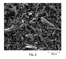
In the first set of embodiments, elongated particles (
1型の細長粒子の中央直径は約3μmであり、細長粒子の直径の90%は2から5マイクロメートル以内にあった。細長粒子の長さは50〜150μmであり、細長粒子の直径が図1に示されている。図2は、1型の細長粒子のSEM顕微鏡写真を示している。
The median diameter of
アルミノケイ酸塩粒子は、50%がアルミナであり、50%がシリカであった。このアルミノケイ酸塩粒子から製造された細長粒子は1から3μmの直径を有した。この細長粒子は、図3に示されたものと同じ直径を有する。図3は、異なるタイプのアルミノケイ酸塩粒子を表す直径の分布を示す。 The aluminosilicate particles were 50% alumina and 50% silica. The elongated particles produced from the aluminosilicate particles had a diameter of 1 to 3 μm. The elongated particles have the same diameter as that shown in FIG. FIG. 3 shows the distribution of diameters representing different types of aluminosilicate particles.
図4は、2型のアルミノケイ酸塩細長粒子のSEM顕微鏡写真を示す。
FIG. 4 shows a SEM micrograph of
酸化物、タルク系および粘土系のコージエライトバッチにおける原材料として、アルミナまたはアルミノケイ酸塩細長粒子を使用した。アルミナおよびシリカ系原材料を一部分または完全に置換した。バッチ中の細長粒子のレベルは、それぞれのバッチ組成物中に含まれる無機原材料に対して10から70質量%に及んだ。 Alumina or aluminosilicate elongated particles were used as raw materials in oxide, talc and clay cordierite batches. Alumina and silica based raw materials were partially or completely replaced. The level of elongated particles in the batch ranged from 10 to 70% by weight with respect to the inorganic raw materials contained in each batch composition.
表1には、様々なバッチ組成物D1〜D12が列記されている。量は、それぞれのバッチ組成物中に含まれる無機原材料に対する質量%で表されて列記されている。バッチ番号D1、D3およびD12は、繊維原材料から得られた無機成分を含有しない比較バッチであった。バッチ組成物D2、D4、D5、およびD10には、アルミナの1型の細長粒子が使用された。バッチ組成物D6、D7、D8、D9、およびD11には、アルミノケイ酸塩の2型の細長粒子が使用された。バッチ組成物D2、D8、D9、D10および比較組成物D1は、酸化物のみの無機含有(すなわち、酸化物)バッチ(すなわち、無粘土、無タルク)であった。バッチ組成物D4および比較組成物D3およびD12は、粘土およびタルク含有(すなわち、粘土−タルク含有)バッチであった。バッチ組成物D7は、無タルク、粘土含有(すなわち、粘土、無タルク)バッチであった。バッチ組成物D5、D6、およびD11は、無粘土、タルク含有(すなわち、タルク、無粘土)バッチであった。ジャガイモデンプン(PS)が、細孔形成剤としてバッチ組成物D1からD4およびD11に含まれ、トウモロコシデンプン(CS)が、細孔形成剤としてバッチ組成物D5からD10およびD12に含まれた。細孔形成剤は、それぞれのバッチ組成物について表1に列記された他の無機材料に対する上乗せ添加として質量%で表1に報告されている。バッチ組成物D2、D3およびD12は、5マイクロメートルの中央粒径を有する「A5」アルミナを含有し、このアルミナは、ここに定義された細長粒子の形態では存在しなかった。バッチ組成物D6およびD11は、3マイクロメートルの中央粒径を有する「A3」アルミナを含有し、このA3アルミナは、ここに定義された細長粒子の形態では存在しなかった。バッチ組成物D3、D4およびD12は、ここに定義された細長粒子の形態では存在しなかった水酸化アルミニウム(Al(OH)3)を含んだ。

ハニカム多孔質セラミック物品をラム押出しにより製造した。このセラミック物品は、コージエライト主相を含み、コージエライト系材料から製造されていると称することができる。1インチ(約2.54cm)のラム押出機を使用した。乾燥繊維ブランケットを、長さが50〜150マイクロメートルの短い断片(segment)の流動性混合物に、2分間に亘り粉砕した。混合の第1工程において、無機非繊維原材料、細孔形成剤および結合剤を予混した。乾燥成分を平鍋内で混ぜ合わせ、混練した。第2の混合工程において、折れた繊維断片を、運転している粉砕機内に供給した。次いで、粉末混合物を、滑らかに流れる乾燥混合物が得られまで、約2〜5分間に亘り乾式混合した。第3の混合工程において、バッチ水を加えた(第3の工程前には、水は加えなかった)。ラム押出しに関して、水の必要量は、無機バッチ材料に基づいて28%〜30%であった。ほとんどの場合、ホモジナイザ(押出機のダイの上流に配置された)および0.006インチ(約0.15mm)の表皮形成領域を有した1インチ(約2.54cm)のマスクの前に、2つの10メッシュの交差スクリーンを使用した。200cpsi(約6.45cm2当たりのセル)/16ミル(約0.41mm)のダイを使用した(cpsi=平方インチ当たりのセル;ミル=インチの千分の一)。押出しは、高押出速度で継ぎ目がなかったのに対し、低速では、表皮に裂け目が生じ、セルが失われた。 Honeycomb porous ceramic articles were produced by ram extrusion. This ceramic article may be referred to as comprising a cordierite main phase and made from a cordierite-based material. A 1 inch (about 2.54 cm) ram extruder was used. The dry fiber blanket was ground into a short segment flowable mixture of 50-150 micrometers in length for 2 minutes. In the first step of mixing, the inorganic non-fibrous raw material, pore former and binder were premixed. The dry ingredients were mixed and kneaded in a flat pan. In the second mixing step, the broken fiber fragments were fed into the operating grinder. The powder mixture was then dry mixed for about 2-5 minutes until a smooth flowing dry mixture was obtained. In the third mixing step, batch water was added (no water was added before the third step). For ram extrusion, the water requirement was 28-30% based on the inorganic batch material. In most cases, before the homogenizer (located upstream of the extruder die) and a 1 inch mask with a 0.006 inch (about 0.15 mm) skin forming area, 2 Two 10 mesh cross screens were used. A 200 cpsi (cell per about 6.45 cm 2 ) / 16 mil (about 0.41 mm) die was used (cpsi = cell per square inch; mil = thousandth of an inch). Extrusion was seamless at high extrusion speeds, whereas at low speeds, the skin was cracked and cells were lost.
次いで、1インチ(約2.54cm)の押出サンプルを市販の1000WのWhirlpoolマイクロ波乾燥機内で乾燥させた。乾燥スケジュールは、3分間に亘り1000Wであり、その後、12時間に亘り90℃での空気乾燥が行われた。 The 1 inch (about 2.54 cm) extruded sample was then dried in a commercial 1000 W Whirlpool microwave dryer. The drying schedule was 1000 W for 3 minutes, followed by air drying at 90 ° C. for 12 hours.
全てのサンプルは、120℃/時の上昇速度を使用して、1410と1435℃の間の最高温度に加熱し、15から30時間に亘り最高温度に保持し、箱形炉内において120℃/時の速度で空気により25℃に冷却した。 All samples were heated to a maximum temperature between 1410 and 1435 ° C. using a ramp rate of 120 ° C./hour, held at the maximum temperature for 15 to 30 hours, and 120 ° C./hour in a box furnace. Cooled to 25 ° C with air at the rate of hour.
焼成部品中に存在した相をX線回折(XRD)により特定した。マルチストリップLynxEye高速検出器を備えたBrukerD4回折システムを利用した。高分解能範囲が典型的に15から100°(2θ)まで得られた。相寄与の定量化のために、リートベルト法を使用した。 The phase present in the fired part was identified by X-ray diffraction (XRD). A Bruker D4 diffraction system equipped with a multi-strip LynxEye fast detector was utilized. A high resolution range was typically obtained from 15 to 100 ° (2θ). The Rietveld method was used for quantification of the phase contribution.
標準走査型電子顕微鏡SEMによる特徴付けを、ハニカム壁面並びに研磨したハニカム壁縦断面(ハニカム通路の方向、すなわち、押出方向に切断された)および研磨されたハニカム断面(ハニカム通路に対して垂直に切断された)に行った。研磨断面の観察について、焼成物品にエポキシを浸透させ、スライスし、研磨した。顕微鏡レベルで存在する気孔率と相の空間分布を、研磨サンプル断面で視覚化した。高分解能SEMを使用して、網状微小構造の詳細と相分布を導いた。SEMについてのエネルギー分散X線分光法による(定性)分析および元素マッピングから、異なる相の化学組成および元素分布を得た。 Characterization by standard scanning electron microscope SEM shows the honeycomb wall as well as the polished honeycomb wall longitudinal section (cut in the direction of the honeycomb passage, ie the extrusion direction) and the polished honeycomb section (cut perpendicular to the honeycomb passage) Went to). For observation of the polished cross section, the fired article was infiltrated with epoxy, sliced and polished. The porosity and phase spatial distribution present at the microscopic level was visualized in the polished sample cross section. A high resolution SEM was used to derive the details of the network microstructure and the phase distribution. From the (qualitative) analysis and element mapping by energy dispersive X-ray spectroscopy for SEM, the chemical composition and element distribution of different phases were obtained.
研磨サンプル断面の方位マッピングにSEMの後方散乱電子回折を使用して、粒径、ハニカム形状に対する存在する相の相対方位およびテキスチャーを導いた。この技法では、SEMにおいて集束入射電子ビームを使用して、高空間分解能を有する局部結晶情報を得る。EBSD検出器は、検体チャンバ内に挿入された蛍光スクリーンからなる。入射電子が検体に衝突するときに、多くがサンプル内の全方位に弾性散乱する。したがって、衝突地点の材料が結晶質である場合、ブラッグの法則(nλ=2dsinθ)に従う適正な軌跡を有するエネルギー電子が存在し、その結果、2つの反対の円錐状の回折された電子が各格子面から生じる。蛍光スクリーンでの回折のこれらの円錐状電子の交差により、適切な結晶面の「d」間隔に比例する厚さを有するバンドを定義する、菊池ラインとして知られる2つの強いラインが生じる。その結果、多数の交差する菊池ラインからなる後方散乱電子回折(EBSD)パターンが形成され、サンプル表面とEBSD検出器との間の幾何学的関係を知ることによって、結晶方位を正確に決定することができる。サンプルを横断して、SEMの入射電子ビームを走査することができるので、優れた空間分解能の定性結晶方位マッピングを得ることができる。菊池パターンは、格子間隔および格子対称性により大きく異なり;したがって、それらを使用して、化学組成変化または格子歪みにおける差による格子パラメータの差である、材料に存在する異なる相を(さらなる化学分析を必要とせずに)識別することができる。 SEM backscattered electron diffraction was used to map the cross section of the polished sample to derive the grain size, relative orientation of the existing phase with respect to the honeycomb shape, and texture. In this technique, a focused incident electron beam is used in an SEM to obtain local crystal information with high spatial resolution. The EBSD detector consists of a fluorescent screen inserted in the specimen chamber. When incident electrons collide with the specimen, many are elastically scattered in all directions in the sample. Thus, if the material at the impact point is crystalline, there will be energetic electrons with the proper trajectory following Bragg's law (nλ = 2dsin θ), so that two opposite conical diffracted electrons will be present in each lattice. Arising from the surface. The intersection of these conical electrons of diffraction on the phosphor screen results in two strong lines known as the Kikuchi line that define a band with a thickness proportional to the “d” spacing of the appropriate crystal plane. As a result, a backscattered electron diffraction (EBSD) pattern consisting of a number of intersecting Kikuchi lines is formed, and the crystal orientation is accurately determined by knowing the geometric relationship between the sample surface and the EBSD detector. Can do. Since the incident electron beam of the SEM can be scanned across the sample, qualitative crystal orientation mapping with excellent spatial resolution can be obtained. Kikuchi patterns vary greatly due to lattice spacing and lattice symmetry; therefore, they can be used to identify different phases present in the material (differences in chemical composition changes or lattice strain differences due to differences in lattice strain). (Without need) can be identified.
サンプルを、真空を使用してエポキシ内に埋め込み、次いで、100℃で一晩、硬化させた。次いで、後方散乱電子は研磨サンプル表面の近い表面領域から収集されるので、サンプルを、注意して、ウェブ面に対して平行(横向きまたは縦断面)かつ押出方向に対して垂直(軸方向または断面)に研磨した。最終研磨は、Red Final Cパッド上の0.05μmコロイドシリカで完了した。研磨後、イリジウム被覆の薄(10Å)層を施して、導電表面を作製し、長いEBSDデータ収集中の帯電問題を回避した。 Samples were embedded in epoxy using vacuum and then cured at 100 ° C. overnight. The backscattered electrons are then collected from the near surface area of the polished sample surface so that the sample is carefully parallel (transverse or longitudinal) to the web surface and perpendicular to the extrusion direction (axial or cross-sectional). ). Final polishing was completed with 0.05 μm colloidal silica on a Red Final C pad. After polishing, a thin (10 cm) layer of iridium coating was applied to create a conductive surface to avoid charging problems during long EBSD data collection.
全てのEBSD分析は、Oxford/HKL EBSDシステムを備えたHitachi SU70 SEMで完了した。データ収集は以下の条件下で完了した:23nAのビーム電流、20kVの加速電位、全体の方位情報について2μmのステップサイズおよび粒径決定に関する0.2μmのステップサイズ。断面積は、ある交点から隣接する交点まで収集し、約1900μm×700μmであった。縦断面積は16の隣接領域(4×4)で収集し、1000μm×700μmの合計画像サイズとなった。完全に焼成したコージエライト材料の特定に使用した相は、コージエライト、ムライト、スピネルなどを含んだ。 All EBSD analyzes were completed with a Hitachi SU70 SEM equipped with an Oxford / HKL EBSD system. Data collection was completed under the following conditions: 23 nA beam current, 20 kV acceleration potential, 2 μm step size for overall orientation information and 0.2 μm step size for particle size determination. The cross-sectional area was collected from one intersection to the adjacent intersection and was about 1900 μm × 700 μm. The longitudinal cross-sectional area was collected in 16 adjacent regions (4 × 4), resulting in a total image size of 1000 μm × 700 μm. Phases used to identify fully fired cordierite materials included cordierite, mullite, spinel, and the like.
EBSDデータの収集後分析は、HKL Map Stitcherを利用して収集した16領域のスティッチングおよび激しいスパイクの除去と平滑化による雑音低減を含んだ。5°のデータの集団化を行うHKL Mamboソフトウェアを使用して、極図点を作成した。極小がc軸方位の最小実験密度に対応し、極大がc軸方位の最大実験密度に対応するように、極図点の密度スケールを調節した。このスケールの極大は、低テキスチャーについては1に近く、強い配向性については高い値に到達する。測定した様々なサンプルにおいて、3の値を有する押出方向(押出軸方向)における負の押出c軸の結晶テキスチャー指数を発見した。 Post-collection analysis of EBSD data included 16-region stitching collected using the HKL Map Stitcher and noise reduction by removal and smoothing of intense spikes. Pole points were generated using HKL Mambo software with 5 ° data clustering. The density scale of the extreme points was adjusted so that the minimum corresponds to the minimum experimental density in the c-axis orientation and the maximum corresponds to the maximum experimental density in the c-axis orientation. The maximum of this scale is close to 1 for low texture and reaches a high value for strong orientation. In the various samples measured, a negative extrusion c-axis crystal texture index in the extrusion direction (extrusion axis direction) having a value of 3 was found.
Autopore IV9500ポロシメータを使用した水銀圧入ポロシメトリーによって、細孔径分布を調査した。この方法では、非湿潤液体および円柱状細孔に関する毛管法を使用する。これは、典型的に、ウォッシュバーンの式D=−(1/P)4ycosΘで表され、式中、Dは細孔直径であり、Pは印加圧力であり、yは表面張力であり、Θは接触角である。水銀の体積は圧力に正比例する。 The pore size distribution was investigated by mercury intrusion porosimetry using an Autopore IV9500 porosimeter. This method uses a capillary method for non-wetting liquids and cylindrical pores. This is typically represented by the Washburn equation D = − (1 / P) 4y cos Θ, where D is the pore diameter, P is the applied pressure, y is the surface tension, Θ Is the contact angle. Mercury volume is directly proportional to pressure.
Micromeritics社のソフトウェアのデータ整理では、微分および対数微分を使用して、計算した対数直径の関数として積算比圧入体積の一次導関数を計算する。 Micromeritics software data reduction uses differential and logarithmic derivatives to calculate the first derivative of the integrated specific press volume as a function of the calculated log diameter.
水銀ポロシメトリーを使用して、浸透率を計算することができる。浸透率は、流体の流速と印加圧力の関係である。Autoporeにおいて、水銀がサンプルにわたる臨界圧力に到達するまで、圧力を増加させ、水銀がより小さな細孔を充填する。これは、典型的に、式k=1/226(Lc)2σ/σ0により表され、式中、σは長さLcでの導電率であり、σ0は細孔中のコンダクタンスであり、ミリダーシーで報告されている。 Mercury porosimetry can be used to calculate permeability. Permeability is the relationship between fluid flow rate and applied pressure. In Autopore, the pressure is increased until the mercury reaches a critical pressure across the sample, and the mercury fills smaller pores. This is typically represented by the equation k = 1/226 (L c ) 2 σ / σ 0 , where σ is the conductivity at length L c and σ 0 is the conductance in the pores. And has been reported by Mildercy.
熱膨張は、0.25インチ(約0.635cm)×0.25インチ(約0.635cm)×2インチ(約5.08cm)の寸法を有する棒形サンプルについて、4℃/分の速度で室温から1200℃まで加熱し、その後、室温まで冷却する最中に測定した。性質の表に報告されたデータについて、試験棒材の長軸はハニカム通路の方向に向けられ、よってハニカム部品の軸方向における熱膨張を提供する。 The thermal expansion is at a rate of 4 ° C./minute for a bar sample having dimensions of 0.25 inch (about 0.635 cm) × 0.25 inch (about 0.635 cm) × 2 inches (about 5.08 cm). Measurements were taken during heating from room temperature to 1200 ° C. and then cooling to room temperature. For the data reported in the properties table, the long axis of the test bar is oriented in the direction of the honeycomb passage, thus providing thermal expansion in the axial direction of the honeycomb part.
様々な温度範囲に関する平均熱膨張係数が性質の表に報告されている。K-1で表されたCTE200-800は、室温から800℃までの温度範囲における平均熱膨張係数としてL(800℃)−L(20℃)/780℃として定義された、室温から800℃までの平均熱膨張係数であり、K-1で表されたCTE200-1000は、室温から1000℃までの温度範囲における平均熱膨張係数としてL(1000℃)−L(20℃)/980℃として定義された、室温から1000℃までの平均熱膨張係数であり、K-1で表されたCTE500-900は、500℃から900℃までの温度範囲における平均熱膨張係数としてL(900℃)−L(500℃)/400℃として定義された、500℃から900℃までの平均熱膨張係数である。CTE500-900は、自動車車両における排気ガス後処理のためのハニカム部品の用途にとって特に重要であり、ここで、このハニカム部品は厳しい急激な温度変化に曝され、500〜900℃の温度範囲は、頻繁に遭遇する動作温度範囲に一致するであろう。 The average coefficient of thermal expansion for various temperature ranges is reported in the properties table. CTE 200-800 expressed as K −1 is defined as L (800 ° C.) − L (20 ° C.) / 780 ° C. as an average coefficient of thermal expansion in a temperature range from room temperature to 800 ° C. CTE 200-1000 represented by K −1 is L (1000 ° C.) − L (20 ° C.) / 980 ° C. as an average thermal expansion coefficient in a temperature range from room temperature to 1000 ° C. CTE 500-900 , expressed as K −1 , is defined as the average coefficient of thermal expansion from room temperature to 1000 ° C., and the average coefficient of thermal expansion in the temperature range from 500 ° C. to 900 ° C. ) -L (500 ° C) / 400 ° C, the average coefficient of thermal expansion from 500 ° C to 900 ° C. CTE 500-900 is particularly important for the application of honeycomb parts for exhaust gas aftertreatment in automobile vehicles, where the honeycomb parts are subjected to severe rapid temperature changes and the temperature range of 500-900 ° C is Will correspond to the frequently encountered operating temperature range.
セラミック材料の強度は、3点または4点曲げを使用して試験することができる。破損前の最大応力が、しばしば、破壊係数またはMORと称される。ここに用いたように、MORは、長さ尺度の平方単位当たりのセルの単位(例えば、平方インチ当たりのセル、すなわちcpsi)で表されたセル密度(CD)および長さ尺度の単位(例えば、インチ)で表されたハニカムマトリクスのセル壁厚TWALLを有するハニカムサンプルの、ASTM C1674−08にしたがう4点曲げ破壊係数試験から得た試験測定を称する。我々は、ASTM C1674−08の試験方法Aを使用した。強度値(4点曲げMOR)は、ここでは、2インチ(50.8mm)の下側長さおよび0.75インチ(19mm)の上側長さを有する4点曲げを使用して測定した。4点曲げ試験の検体外形は、長さが2.5インチ(63.5mm)、幅が0.5インチ(12.7mm)、厚さが0.25インチ(6.4mm)であった。使用した力測定システムは、最大力の読出し装置および校正された荷重セルを備えていた。試験した全ての検体は、長手方向に通路を有する正方形のセルラ(ハニカム)を有した。壁強度(σwall)としばしば称される実際の材料強度は、このセルラ構造について計算することによって決定しなければならない。材料強度の別の尺度は「正規化強度」であり、これは、材料の気孔率並びにMOR試験サンプルの外形を考慮し、ここで、正規化強度は、(MOR)(relCFA)-1(1−気孔率/100)-1とここに定義され、式中、relCFAは、relCFA=TWALL[2L−TWALL]/L2とここに定義される相対閉鎖前方面積であり、式中、L=CD1/2であり、気孔率は、水銀圧入ポロシメトリーにより測定された、%で表される全気孔率である。セル密度(CD)は、長さ尺度の平方単位当たりのセルの単位(例えば、平方インチ当たりのセル、すなわちcpsi)で表され、ハニカムマトリクスのセル壁厚TWALLは、長さ尺度の対応する単位(例えば、インチ)で表される。 The strength of the ceramic material can be tested using 3-point or 4-point bending. The maximum stress before failure is often referred to as the failure factor or MOR. As used herein, MOR is the cell density (CD) expressed in units of cells per square unit of length scale (eg, cells per square inch, or cpsi) and units of length scale (eg, , Inches) refers to a test measurement obtained from a four-point bending failure factor test according to ASTM C1674-08 of a honeycomb sample having a honeycomb matrix cell wall thickness T WALL expressed in inches. We used ASTM C1674-08 Test Method A. The strength values (4-point bend MOR) were measured here using a 4-point bend having a lower length of 2 inches (50.8 mm) and an upper length of 0.75 inches (19 mm). The specimen outline of the 4-point bending test was 2.5 inches (63.5 mm) in length, 0.5 inches (12.7 mm) in width, and 0.25 inches (6.4 mm) in thickness. The force measurement system used was equipped with a maximum force readout and a calibrated load cell. All specimens tested had a square cellular (honeycomb) with a passage in the longitudinal direction. The actual material strength, often referred to as wall strength (σ wall ), must be determined by calculating for this cellular structure. Another measure of material strength is “normalized strength”, which takes into account the porosity of the material as well as the profile of the MOR test sample, where the normalized strength is (MOR) (relCFA) −1 (1 −porosity / 100) −1 , where relCFA is the relative closed front area defined here as relCFA = T WALL [2L−T WALL ] / L 2 , where L = CD1 / 2 , and the porosity is the total porosity expressed in%, measured by mercury intrusion porosimetry. The cell density (CD) is expressed in units of cells per square unit of the length scale (eg, cells per square inch or cpsi), and the cell wall thickness T WALL of the honeycomb matrix corresponds to the length scale. Expressed in units (eg, inches).
5インチ(約12.5cm)×1インチ(約2.54cm)×0.5インチ(約1.27cm)の寸法を有し、ハニカム通路の方向に縦軸が向けられた棒形サンプルを使用して、曲げ共振周波数によって弾性率を測定した。サンプルを1200℃に加熱し、冷却して室温まで戻した。各温度について、弾性率を共振周波数から直接導き、ASTM C1198−01を参照して、サンプルの外形および質量について正規化した。 Uses a rod-shaped sample having dimensions of 5 inches (about 12.5 cm) × 1 inch (about 2.54 cm) × 0.5 inches (about 1.27 cm) and with the longitudinal axis oriented in the direction of the honeycomb passage. Then, the elastic modulus was measured by the bending resonance frequency. The sample was heated to 1200 ° C. and cooled to room temperature. For each temperature, the modulus was derived directly from the resonant frequency and normalized for sample geometry and mass with reference to ASTM C1198-01.
コージエライトバッチに1型または2型の細長粒子を使用すると、網状微小構造を有する、多孔質の低膨張コージエライトセラミックが生成された。これにより、微粒子のみの無機原料により製造された比較セラミック(1型も2型も、細長粒子を含まない)と比べて、改善された性質が得られることが分かった。網状微小構造において、セラミック製品の結晶粒は、多結晶ストランドに組織化され、細長細孔を取り囲む。図5〜6は、バッチ原材料としてアルミナまたはアルミノケイ酸塩細長粒子からここに製造されたコージエライト材料の網状微小構造の代表的なSEM画像を示す。低い倍率の画像は、高い気孔率のセラミックの網状微小構造を示し、より高い倍率のSEM画像は、原材料の細長粒子のテンプレートおよび粒状原材料から焼成中の固体反応により形成するストランドの多結晶性質を明らかにする。
The use of
網状のコージエライト微小構造は、アルミナ、アルミノケイ酸塩およびシリカの細長粒子により、並びにバッチ中の異なる細長粒子の量により得た。網状微小構造は、それらの多結晶ストランドの幅、相互接続性、開気孔率および形状において差がある幅広い網目構造に及ぶ。微小構造の詳細は、バッチに使用される細長粒子の量、組成および形状、バッチ中の細孔形成剤および焼成サイクルに依存する。特に良好な結果が、酸化物系バッチ原材料(すなわち、粘土やタルクを含有しないバッチ)で得られた。微粒子のみのバッチ(すなわち、バッチ中に1型も2型も、細長粒子を含まない)から由来の公知の材料において、酸化物、粘土/タルク、タルク系および粘土系のコージエライトバッチの間で微小構造の大きい差が報告された。理論により拘束するものではないが、微粒子のみのバッチから製造された材料と、本開示の細長粒子を含有するバッチから製造された材料との間の差は、中間体生成物としてのスピネルまたはムライトの形成または中間体ガラス相の量およびコージエライト形成におけるその役割などの、反応結果における差に関連すると考えられる。強力な反応結果関連の微小構造刺激要因は、細長粒子のコージエライトバッチについて特定されていなかった。ここに開示された網状コージエライトの場合、微小構造の形成は、前駆体の細長粒子のテンプレートによって決定されると思われる。実施の形態、特に酸化物バッチから形成された実施の形態について、非常にわずかで、あるとしてもごく微量のガラス相またはガラスが、ここに開示された焼成多孔質材料中に存在する、すなわち、コージエライト主相を含む多孔質セラミック材料は、1質量%未満のガラス相、または0.1質量%未満のガラス相、または検出可能な微量に過ぎないガラスを含有する。
A reticulated cordierite microstructure was obtained with elongated particles of alumina, aluminosilicate and silica and with the amount of different elongated particles in the batch. Reticulated microstructures span a wide range of networks with differences in the width, interconnectivity, open porosity and shape of their polycrystalline strands. The details of the microstructure depend on the amount, composition and shape of the elongated particles used in the batch, the pore former in the batch and the firing cycle. Particularly good results have been obtained with oxide-based batch raw materials (ie batches containing no clay or talc). In known materials derived from fines-only batches (ie, neither
異なる網状コージエライト材料サンプルおよびそれらの微粒子の比較サンプルの性質が表2にまとめられている。d10、d50、d90などの値はマイクロメートルの単位で表され、気孔率%は無次元であり、細孔径および気孔率は、水銀圧入ポロシメトリーにより測定されている。一例として、d10、d50、およびd90の値は、体積基準の全細孔径分布の10%、50%、および90%での細孔直径である。具体的に、d10は、90%の積算水銀圧入体積での細孔直径であり、d50は、50%の積算水銀圧入体積での細孔直径であり、d90は、10%の積算水銀圧入体積での細孔直径である。それゆえ、体積基準で、細孔の10%はd10より小さく、細孔の50%はd50より小さく、細孔の90%はd90より小さい。
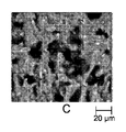
1型の細長粒子を有する酸化物バッチ(バッチ組成物D2およびD10:サンプル番号2、11、14)において、コージエライトは、ストランドの外側で小面が終わる別個の小さなコージエライト結晶からなる絡み合ったストランドの微細な微小構造に成長した。それぞれ、図5A、5B、および5Cにおけるサンプル14のSEM A、B、およびCを参照のこと。ストランドは、10〜20マイクロメートルの直径を有し、強力に連結されており、多数の分岐を示す。焼成壁面において、個々の結晶のサイズは2から5マイクロメートルに及ぶ。図5A〜5Cは、1430℃に焼成した後のサンプル14(バッチ組成物D10、36質量%の1型の細長粒子を有する酸化物バッチ)の焼成壁面のSEM図を示す。
In oxide batches with
サンプル14の研磨された断面および縦断面上の方位マッピングは、押出方向に負の膨張方向を有する成長したコージエライトの強力な優先配向性を示した。
Orientation mapping on the polished and longitudinal sections of
約9μmの中央「結晶粒」サイズが、1.5度のミスオリエンテーションに関して決定された。個々の晶子は、それより小さい2〜5マイクロメートルであると思われる。個々の結晶粒は等軸形状を有した。それらは、ストランドの方向に細長くなっていなかった。 A central “grain” size of about 9 μm was determined for a 1.5 degree misorientation. Individual crystallites appear to be smaller, 2-5 micrometers. Individual crystal grains had an equiaxed shape. They were not elongated in the direction of the strands.
トウモロコシデンプンの代わりに、ジャガイモデンプンを細孔形成剤として使用した場合、より大きい細孔径と、より大きい領域サイズにより、より粗い微小構造を得ることができる。 When potato starch is used as a pore former instead of corn starch, a coarser microstructure can be obtained with a larger pore size and larger region size.
バッチレベルにおける低細長粒子、例えば、10質量%の1型細長粒子(バッチ組成D2)について、微小構造は、微粒子のみのバッチからのコージエライトのものとより多くの類似性を有するが、それでも、網状コージエライトの特徴を示す。サンプル2について、典型的な領域寸法は約50マイクロメートルであり、それらの領域はそれほど細長くない。押出方向における優先配向性は、低細長粒子含有量およびより粗い細孔形成剤のために、より低い。その両者のために、押出方向からの細長粒子の最大軸の逸脱が大きくなり、優先押出方向の周りのコージエライトの負の膨張c軸のずれが大きくなる。
For low elongate particles at the batch level, eg, 10 wt
異なる領域間での15度のミスオリエンテーションの区別基準に基づいて、バッチ組成D10(サンプル11および14について)について、直径が23μmであり、長さが35μmである平均の領域寸法が分かった。領域は、押出方向において細長くなっている。バッチに2型の細長粒子を使用した実施の形態(バッチ組成D8およびD9;サンプル番号9、12、10、13)について、反応順序が変えられ、中間体反応生成物としてムライトが形成される。このタイプの反応順序において、一般に、コージエライトの成長は、中間体ガラスの分布により制御され、かなり等方性である。1430℃での焼成後の50質量%の2型の細長粒子を有する酸化物バッチである、サンプル13の焼成されたままの壁面に関する図6A〜6Cに示されるように、アルミノケイ酸塩細長粒子は、1型の細長粒子から形成された網状微小構造のものと類似の網状微小構造を生じる。重ねて、細孔構造は異方性であり、細孔は押出方向において細長くなっている。D10のバッチと比べると、焼成表面はより滑らかであり、この材料の比表面積は小さい。
Based on the 15 degree misorientation distinction between different regions, an average region dimension of 23 μm in diameter and 35 μm in length was found for batch composition D10 (for samples 11 and 14). The region is elongated in the extrusion direction. For
方位マッピングにより、アルミノケイ酸塩細長粒子の使用による優先配向性が判明したが、アルミナの豊富な細長粒子によるよりも小さかった。縦断面では、優先配向性因子は2.5であり、断面では、決定された因子はわずかに小さく1.8であった。 Orientation mapping revealed preferential orientation due to the use of aluminosilicate elongated particles, but was smaller than with alumina-rich elongated particles. In the longitudinal section, the preferred orientation factor was 2.5, and in the section, the determined factor was slightly smaller, 1.8.
10μmの中央結晶粒サイズが、結晶粒剥離の1.5度のミスオリエンテーション基準を使用して決定された。 A median grain size of 10 μm was determined using a 1.5 degree misorientation criterion for grain separation.
領域は楕円形状を有し、平均領域長さはストランドに沿って40μmであり、直径は25μmであった。15°のミスオリエンテーション基準を使用して、領域を決定した。 The region had an elliptical shape, the average region length was 40 μm along the strand, and the diameter was 25 μm. The area was determined using a 15 ° misorientation criterion.
図7A〜7Cは、36%の1型細長粒子(バッチ番号D10)(左側)、50%の2型アルミノケイ酸塩細長粒子(バッチ番号D9)(中央)および70%の2型細長粒子(バッチ番号D8)(右側)を含む酸化物バッチから製造された網状コージエライトの焼成されたままの壁面、研磨断面および研磨縦断面の顕微鏡写真を示している。
7A-7C show 36
アルミナまたはアルミノケイ酸塩から製造された細長粒子と共にタルクまたは粘土から製造された網状コージエライト材料は、タルク系バッチ番号D5から得られた図8のサンプル6のSEM顕微鏡写真に見られるように、より粗い微小構造を有する。しかしながら、網状コージエライト材料における相および相部分は、対応する微粒子のみの参照材料と比べて変わっていない。X線回折および局部的化学分析により、どのような著しい差も判明しない。図9および10は、非酸化物バッチから製造された網状コージエライト材料の焼成されたままの壁面および研磨断面のSEM顕微鏡写真(それぞれ、タルク系バッチ番号D6/サンプル7、およびタルク系バッチ番号D7/サンプル8)を示す。
The reticulated cordierite material made from talc or clay with elongated particles made from alumina or aluminosilicate is coarser as seen in the SEM micrograph of sample 6 of FIG. 8 obtained from talc-based batch number D5. Has a microstructure. However, the phase and phase portion in the reticulated cordierite material remains unchanged compared to the corresponding particulate only reference material. X-ray diffraction and local chemical analysis do not reveal any significant differences. FIGS. 9 and 10 show SEM micrographs of as-fired walls and polished cross-sections of reticulated cordierite material made from non-oxide batches (talc batch number D6 /
表2の実施例から分かるように、本開示による網状コージエライトは、実質的に同じ気孔率および中央細孔径について、比較の微粒子のみに由来のコージエライトよりも高い材料強度を示す。ここに開示された網状コージエライトの強度は、比較コージエライト材料のものの2倍または3倍になり得ることが分かった。例えば、同様の気孔率および同様の中央細孔径を有するアルミノケイ酸塩細長粒子を有する酸化物バッチについて、強度が実質的に3倍になったのが観察された(例えば、サンプル9および10をサンプルD1と比較)。
As can be seen from the examples in Table 2, reticulated cordierite according to the present disclosure exhibits higher material strength than cordierite derived from comparative microparticles only for substantially the same porosity and median pore size. It has been found that the strength of the reticulated cordierite disclosed herein can be twice or three times that of the comparative cordierite material. For example, for oxide batches having aluminosilicate elongated particles with similar porosity and similar median pore diameter, it was observed that the strength was substantially tripled (eg,
1型細長粒子を有する酸化物バッチにおいて、同様の気孔率で、中央細孔径の著しい増加が観察され、d50の増加にもかかわらず、強度が著しく増加した(例えば、サンプル2および11をサンプル1と比較)。すなわち、公知のコージエライト組成物において、強度は、典型的に、d50が増加するにつれて、著しく減少するにもかかわらず、強度の増加が観察された。
In oxide batches with
細長粒子を有する粘土、タルクおよび粘土−タルクバッチは、同様に気孔率で中央細孔径が増加したにもかかわらず、強度の著しい増加を示した(例えば、サンプル5をサンプル4と比較)。公知のコージエライト組成物では、d50が増加するにつれて、強度は減少することが予測されるが、強度は相当増加した。 Clay, talc and clay-talc batches with elongated particles also showed a significant increase in strength despite the increase in porosity and median pore diameter (eg, compare sample 5 with sample 4). In known cordierite compositions, the strength is expected to decrease as d50 increases, but the strength has increased considerably.
細長粒子を使用した、ここに開示されたコージエライトバッチは、多孔質セラミック材料の完全に焼成されたときの強度を増加させるだけでなく、開示された網状コージエライトは、未焼成物品から完全焼成物品までの幅広い焼成温度に亘り、未焼成強度と中間体焼成強度における著しい改善を示すことが分かった。 The cordierite batch disclosed herein using elongated particles not only increases the strength of the porous ceramic material when fully fired, but the disclosed reticulated cordierite is fully fired from the green article. It has been found that over a wide range of firing temperatures up to the article, there is a significant improvement in unfired and intermediate fired strength.
2型細長粒子を有する酸化物バッチから得られた網状コージエライトの弾性率は、公知のコージエライト組成物と比べて、非常にわずかしかヒステリシスを示さない。例えば、図11は、温度(℃)の関数としてプロットされたpsiの単位で表された軸方向ヤング率(「弾性率」)を示しており、これは、1430℃で焼成された2型細長粒子を47質量%有する酸化物バッチ番号D8から形成されたサンプル12の加熱および冷却サイクル中に生じた。これらの曲線は、微小亀裂の形成されていないコージエライトに典型的に得られる挙動と強い類似性を示す。
The elastic modulus of reticulated cordierite obtained from oxide batches with
比較のために、加熱(右向き矢印)および冷却(左向き矢印)中の温度(℃)に対する、微小亀裂の形成されたコージエライトセラミック(サンプル3、バッチD12;バッチ中の細長粒子から形成されていない)の弾性率(psiで表されている)が図12に示されており、これは、微小亀裂の形成されたコージエライトの加熱および冷却サイクル中の弾性率のヒステリシスを示す。
For comparison, microcracked cordierite ceramic (
同じ気孔率で、微小亀裂の形成された微粒子コージエライトセラミックの弾性率は、微小亀裂の形成されていないセラミックのものよりも低く、ここに開示された対応する網状コージエライトのものよりも低い。このことは、網状コージエライトが、典型的な公知の微小亀裂の形成されたコージエライトよりも低い微小亀裂密度を有することを表す。ここに開示された網状コージエライトの弾性率は、典型的な公知の微小亀裂の形成されたコージエライトのものよりもずっと低く、ある実施の形態においては、網状コージエライトは取るに足らない微小亀裂密度を有することが分かった。 At the same porosity, the modulus of the microcracked fine-grain cordierite ceramic is lower than that of the non-microcracked ceramic and lower than that of the corresponding reticulated cordierite disclosed herein. This represents that reticulated cordierite has a lower microcrack density than typical known microcracked cordierite. The elastic modulus of the reticulated cordierite disclosed herein is much lower than that of the typical known microcracked cordierite, and in certain embodiments, the reticulated cordierite has a negligible microcrack density. I understood that.
図12から分かるように、対照の微小亀裂の形成されたコージエライトセラミックの加熱および冷却サイクルにおける弾性率は、大きいヒステリシスを示し、これは、理論により拘束するものではないが、約700℃超の温度への加熱中に、材料中の微小亀裂が閉じ始め、これにより、約700℃から1200℃までの温度範囲における加熱中に弾性率が増加することに関連すると考えられる。1200℃辺りで、微小亀裂は、一般に、ほとんどのコージエライト材料において閉じられ、その温度では微小亀裂の形成されていないセラミックが得られる。1200℃から室温までの冷却サイクルにおいて、弾性率曲線は、最初に、わずかな負の勾配を有する直線により特徴付けられる、微小亀裂の形成されていないセラミックのものにしたがう。その勾配は、二次相が寄与しながら、コージエライトセラミックの固有の弾性率により決定される。冷却中に臨界局部応力に到達したときに、微小亀裂が、さらなる冷却中に形成し始める。冷却中の微小亀裂の形成の開始は、500℃未満の温度について、弾性率冷却曲線に観察される。次いで、弾性率は、温度の減少と共に減少し、増加する微小亀裂の形成を反映する。室温では、冷却曲線の弾性率は、最終的に、加熱曲線の元の出発値に到達し、これは、微小亀裂の形成されたセラミックの室温での弾性率EMC RTである。室温での微小亀裂の形成されていないセラミックの仮想弾性率ENMC RTは、前記直線を室温まで外挿することによって、600℃から1000℃までの温度範囲における冷却曲線の直線部分から導くことができる。ENMC RT=E1000℃−975・(E1000℃−E600℃)/400。加熱弾性率曲線と冷却弾性率曲線との間のヒステリシスの度合いは、室温での材料の微小亀裂密度を反映する。微小亀裂密度は、微小亀裂の形成された材料の弾性率EMC RTおよび対応する微小亀裂の形成されていない材料の(実際の)弾性率ENMC RTの比率に比例する。MCD=(9/16)[ENMC RT/EMC RT]と定義されるパラメータMCDは、微小亀裂網目構造密度の尺度として使用される。微小亀裂が形成されていないセラミックでは、MCD=0であり、低い微小亀裂密度(一般に、MCD<0.2)のコージエライトでは、MCDは小さく、強力に微小亀裂が形成されたコージエライトでは、MCD>0.5である。 As can be seen from FIG. 12, the modulus of elasticity in the heating and cooling cycle of the control microcracked cordierite ceramic shows large hysteresis, which is not bound by theory, but is above about 700 ° C. It is believed that the microcracks in the material begin to close during heating to a temperature of 5 ° C., which increases the modulus of elasticity during heating in the temperature range from about 700 ° C. to 1200 ° C. Around 1200 ° C., microcracks are generally closed in most cordierite materials, resulting in a ceramic with no microcracks formed at that temperature. In a cooling cycle from 1200 ° C. to room temperature, the elastic modulus curve initially follows that of a ceramic with no microcracks, characterized by a straight line with a slight negative slope. The gradient is determined by the intrinsic modulus of cordierite ceramic, with the secondary phase contributing. When critical local stress is reached during cooling, microcracks begin to form during further cooling. The onset of microcrack formation during cooling is observed in the elastic modulus cooling curve for temperatures below 500 ° C. The modulus then decreases with decreasing temperature, reflecting increasing microcrack formation. At room temperature, the elastic modulus of the cooling curve eventually reaches the original starting value of the heating curve, which is the elastic modulus E MC RT at room temperature of the microcracked ceramic. The virtual elastic modulus E NMC RT of a ceramic without microcracks at room temperature can be derived from the linear part of the cooling curve in the temperature range from 600 ° C. to 1000 ° C. by extrapolating the straight line to room temperature. it can. E NMC RT = E 1000 ° C. −975 · (E 1000 ° C.− E 600 ° C. ) / 400. The degree of hysteresis between the heating modulus curve and the cooling modulus curve reflects the microcrack density of the material at room temperature. The microcrack density is proportional to the ratio of the elastic modulus E MC RT of the microcracked material and the (actual) elastic modulus E NMC RT of the corresponding non-microcracked material. The parameter MCD, defined as MCD = (9/16) [E NMC RT / E MC RT ], is used as a measure of the microcrack network density. For ceramics without microcracks, MCD = 0, for cordierite with low microcrack density (generally MCD <0.2), the MCD is small, and for cordierite with strong microcracks, MCD> 0.5.
網状コージエライト(例えば、図11に示された2型細長粒子を有する酸化物バッチ)のMCDは、非常に小さく、1に近く、これは、材料中の微小亀裂のレベルが非常に低いことを表すことが分かった。いくつかのサンプルにおいて、網状コージエライト酸化物バッチは、微小亀裂をほとんど示さない。ある実施の形態において、ここに開示された多孔質セラミック物品のコージエライト相は、0.15未満、さらには0.10未満の微小亀裂密度(MCD)を有する。ある実施の形態において、ここに開示された多孔質セラミック物品は、室温(20℃)で微小亀裂が形成されていない。
The MCD of reticulated cordierite (eg, the oxide batch with
バッチ中で様々な細孔形成剤および量を実施することにより、ここに開示された網状コージエライトで、改善された強度に加え、様々な所望の性質を提供できる。例えば、細孔径分布を狭くして、低d因子、例えば、(d50−d10)/d50<0.3を達成することができる。 By implementing various pore formers and amounts in the batch, the reticulated cordierite disclosed herein can provide various desired properties in addition to improved strength. For example, the pore size distribution can be narrowed to achieve a low d factor, eg, (d50−d10) / d50 <0.3.
いくつかの網状微小構造の細孔径分布が図13〜14に示されており、これらは、μmで表された細孔径に対して、水銀圧入ポロシメトリーによる微分圧入体積をプロットしている。比較コージエライトの細孔径分布も示されている。図13は、バッチ中に小さな粒径の細孔形成剤(トウモロコシデンプン(CS))および大きな粒径の細孔形成剤(ジャガイモデンプン(PS))を含む、1型と2型の細長粒子両方から製造された細長粒子を含む酸化物バッチの様々な実施の形態の細孔径分布を示している。
The pore size distributions of several network microstructures are shown in FIGS. 13-14, which plot the differential intrusion volume by mercury intrusion porosimetry against the pore size expressed in μm. The pore size distribution of comparative cordierite is also shown. FIG. 13 shows both
図14は、両方の型の細長粒子、および粗い(PS)または微細な(CS)細孔形成剤を含む、粘土−タルク、タルクまたは粘土バッチから製造された網状コージエライトの様々な実施の形態の細孔径分布を示している。微粒子対照材料も、比較のために提示されている。 FIG. 14 shows various embodiments of reticulated cordierite made from clay-talc, talc or clay batches containing both types of elongated particles and coarse (PS) or fine (CS) pore formers. The pore size distribution is shown. A particulate control material is also presented for comparison.
表2と図13〜14から分かるように、本開示にしたがえば、高いD50、さらには高いD50と高強度を有する多孔質セラミックを得ることができる。これらの実施の形態のいくつかにおいて、気孔率を極めて高くすることができる。ある実施の形態において、D50は、10μmより大きく、これらの実施の形態のいくつかにおいて、20μmより大きく、これらの実施の形態のいくつかにおいて、30μmより大きく、これらの実施の形態のいくつかにおいて、50μmより大きい。ある実施の形態において、D50は25μmより大きく、正規化強度は15MPaより大きい。ある実施の形態において、D50は25μmより大きく、正規化強度は20MPaより大きい。ある実施の形態において、D50は25μmより大きく、気孔率は45%より大きい、または50%より大きい、さらには55%より大きい。ある実施の形態において、D50は25μmより大きく、正規化強度は15MPaより大きく、気孔率は45%より大きい、または50%より大きい、さらには55%より大きい。ある実施の形態において、D50は25μmより大きく、正規化強度は20MPaより大きく、気孔率は45%より大きく、さらには50%より大きい。 As can be seen from Table 2 and FIGS. 13 to 14, according to the present disclosure, a porous ceramic having a high D50, a high D50 and a high strength can be obtained. In some of these embodiments, the porosity can be very high. In some embodiments, D50 is greater than 10 μm, in some of these embodiments, greater than 20 μm, in some of these embodiments, greater than 30 μm, in some of these embodiments. Larger than 50 μm. In certain embodiments, D50 is greater than 25 μm and the normalized strength is greater than 15 MPa. In certain embodiments, D50 is greater than 25 μm and the normalized strength is greater than 20 MPa. In certain embodiments, D50 is greater than 25 μm and the porosity is greater than 45%, or greater than 50%, and even greater than 55%. In certain embodiments, D50 is greater than 25 μm, normalized strength is greater than 15 MPa, and porosity is greater than 45%, or greater than 50%, and even greater than 55%. In certain embodiments, D50 is greater than 25 μm, normalized strength is greater than 20 MPa, porosity is greater than 45%, and even greater than 50%.
表2と図13〜14から分かるように、本開示にしたがえば、低いD50、さらには低いD50と高強度を有する多孔質セラミックを得ることができる。これらの実施の形態のいくつかにおいて、気孔率を極めて高くすることができる。ある実施の形態において、D50は15μm未満であり、正規化強度は15MPaより大きい。ある実施の形態において、D50は15μm未満であり、正規化強度は20MPaより大きい。ある実施の形態において、D50は15μm未満であり、正規化強度は15MPaより大きく、気孔率は50%より大きく、これらの実施の形態のいくつかにおいて、さらには55%より大きい。ある実施の形態において、D50は15μm未満であり、正規化強度は20MPaより大きく、気孔率は50%より大きく、これらの実施の形態のいくつかにおいて、さらには55%より大きい。 As can be seen from Table 2 and FIGS. 13 to 14, according to the present disclosure, a porous ceramic having a low D50, a low D50 and a high strength can be obtained. In some of these embodiments, the porosity can be very high. In certain embodiments, D50 is less than 15 μm and the normalized strength is greater than 15 MPa. In certain embodiments, D50 is less than 15 μm and the normalized strength is greater than 20 MPa. In certain embodiments, D50 is less than 15 μm, the normalized strength is greater than 15 MPa, the porosity is greater than 50%, and in some of these embodiments, even greater than 55%. In certain embodiments, D50 is less than 15 μm, normalized strength is greater than 20 MPa, porosity is greater than 50%, and in some of these embodiments, even greater than 55%.
ここに開示された網状微小構造を有するコージエライト材料は、低い熱膨張、すなわち、15×10-7/K未満、ある実施の形態において、10×10-7/K未満の熱膨張係数を有する。基体およびフィルタとしての用途のための改善された耐熱衝撃性が、高強度および低い熱膨張の組合せから得ることができる。それに加え、様々な実施の形態の熱膨張加熱および冷却曲線はわずかなヒステリシスを示し、このことは、これらの材料における微小亀裂密度が極めて低いことを表す。 Cordierite materials having a reticulated microstructure disclosed herein have a low thermal expansion, that is, a coefficient of thermal expansion of less than 15 × 10 −7 / K, and in some embodiments, less than 10 × 10 −7 / K. Improved thermal shock resistance for substrate and filter applications can be obtained from a combination of high strength and low thermal expansion. In addition, the thermal expansion heating and cooling curves of the various embodiments show a slight hysteresis, indicating that the microcrack density in these materials is very low.
図15は、ヒステリシスが取るに足らない、本開示による2型細長粒子を有する酸化物バッチの代表的な実施例についての熱膨張加熱および冷却曲線(℃で表された温度に対するppmで表されたデルタL/L)を示している。
FIG. 15 is a thermal expansion heating and cooling curve (expressed in ppm versus temperature expressed in ° C.) for an exemplary embodiment of an oxide
図16は、ヒステリシスが取るに足らない、45質量%の2型細長粒子を有するタルク系バッチから製造されたサンプル7についての熱膨張加熱および冷却曲線(℃で表された温度に対するppmで表されたデルタL/L)を示している。
FIG. 16 shows thermal expansion heating and cooling curves (expressed in ppm vs. temperature expressed in ° C.) for
コージエライトバッチに1型または2型の細長粒子を使用すると、一般に、小さなコージエライト結晶粒が大きなストランド内に網状網目構造に束ねられる網状微小構造が生成されることが分かった。網状構造において、コージエライト材料は、押出方向(押出中の前駆体の細長粒子の配向性方向)にc軸を有する優先的結晶方位を示す。理論により拘束されるものではないが、未焼成物品における細長粒子の充填挙動により、コージエライトの結晶粒サイズおよび領域サイズの成長が制限され、よって、その結果得られた材料は、細長粒子から製造されていない比較のコージエライト材料のものよりも低い微小亀裂密度を有すると考えられる。すなわち、配向性および小さな領域サイズにより、材料強度の増加に関連している、網状コージエライトの低い、さらには取るに足らない微小亀裂密度が生じる。繊維性材料から製造された細長粒子は、同じ気孔率の微粒子材料よりも、高い表面積を有し、より小さい微小亀裂密度も示す。網状コージエライトは、公知のコージエライトの微小構造と比べて、熱衝撃、振動または衝突などのより大きい機械的外力に耐える、より大きい能力を提供し、それゆえ、高耐熱衝撃性および/または高耐久性(強度)の用途に使用してもよい。
It has been found that the use of
ある態様において、コージエライト主相からなる多孔質セラミック材料がここに開示され、この多孔質セラミック材料は、15MPa超の正規化強度、(MOR)(relCFA)-1(1−気孔率/100)-1を示し、式中、MORは、長さ尺度の平方単位当たりのセルの単位で表されたセル密度(CD)および長さ尺度の単位で表されたハニカムマトリクスのセル壁厚(TWALL)を有するハニカムサンプルの、ASTM C1674−08にしたがう4点曲げ破壊係数試験から得たMPaの単位で表された値であり、relCFAは、relCFA=TWALL[2L−TWALL]/L2とここに定義される相対閉鎖前方面積であり、L=CD1/2であり、気孔率は、水銀圧入ポロシメトリーにより測定された、%で表される全気孔率である。 In one embodiment, a porous ceramic material comprising a cordierite main phase is disclosed herein, wherein the porous ceramic material has a normalized strength of greater than 15 MPa, (MOR) (relCFA) −1 (1-porosity / 100) − 1 where MOR is the cell density (CD) expressed in units of cells per square unit of length scale and the cell wall thickness (T WALL ) of the honeycomb matrix expressed in units of length scale Is a value expressed in units of MPa obtained from a 4-point bending fracture coefficient test according to ASTM C1674-08, and relCFA is relCFA = T WALL [2L−T WALL ] / L 2 Is the relative closed front area as defined by: L = CD1 / 2 , and the porosity is the total porosity expressed in%, measured by mercury intrusion porosimetry.
ある実施の形態において、多孔質セラミック材料は、1質量%未満のガラス相を、ある実施の形態において、0.1質量%未満のガラス相を、ある実施の形態において、さらには0.01質量%未満のガラス相を有する。 In certain embodiments, the porous ceramic material has less than 1% by weight glass phase, in certain embodiments less than 0.1% by weight glass phase, in certain embodiments, even 0.01% by weight. % Of glass phase.
ある実施の形態において、多孔質セラミック材料は、20MPa超の、ある実施の形態において、25MPa超の、ある実施の形態において、さらには30MPa超の正規化強度を示す。 In certain embodiments, the porous ceramic material exhibits a normalized strength of greater than 20 MPa, in certain embodiments, greater than 25 MPa, in certain embodiments, and even greater than 30 MPa.
ある実施の形態において、多孔質セラミック材料は、45%以上の、ある実施の形態において、50%以上の、ある実施の形態において、55%以上の、ある実施の形態において、45から60%の全気孔率を有する。 In some embodiments, the porous ceramic material is 45% or more, in some embodiments, 50% or more, in some embodiments, 55% or more, in some embodiments 45-60%. Has total porosity.
ある実施の形態において、多孔質セラミック材料は、5.0μm超の、ある実施の形態において、10.0μm超の、ある実施の形態において、15.0μm超の、ある実施の形態において、20.0μm超の、ある実施の形態において、25.0μm超の、ある実施の形態において、30.0μm超のd50を有する。 In certain embodiments, the porous ceramic material is greater than 5.0 μm, in certain embodiments, greater than 10.0 μm, in certain embodiments, greater than 15.0 μm, in certain embodiments. In some embodiments greater than 0 μm, in some embodiments greater than 25.0 μm, in certain embodiments, have a d50 greater than 30.0 μm.
ある実施の形態において、多孔質セラミック材料は、1.00未満の、ある実施の形態において、0.70未満の、ある実施の形態において、0.60未満の、ある実施の形態において、0.50未満の、ある実施の形態において、0.40未満の、ある実施の形態において、0.30未満、ある実施の形態において、0.25未満のd因子(「dF」)=(d50−d10)/d50を有する。 In some embodiments, the porous ceramic material is less than 1.00, in some embodiments, less than 0.70, in some embodiments, less than 0.60, in some embodiments,. In some embodiments, less than 50, in less than 0.40, in some embodiments, less than 0.30, in some embodiments, less than 0.25 d-factor (“d F ”) = (d50− d10) / d50.
ある実施の形態において、多孔質セラミック材料は、20MPa超の正規化強度を示し、45%以上の全気孔率を有する。ある実施の形態において、多孔質セラミック材料は、25MPa超の正規化強度を示し、50%以上の全気孔率を有する。ある実施の形態において、多孔質セラミック材料は、30MPa超の正規化強度を示し、55%以上の全気孔率を有する。ある実施の形態において、多孔質セラミック材料は、25MPa超の正規化強度を示し、45%以上の全気孔率を有する。ある実施の形態において、多孔質セラミック材料は、20MPa超の正規化強度を示し、50から60%の全気孔率を有する。ある実施の形態において、多孔質セラミック材料は、20MPa超の正規化強度を示し、45から55%の全気孔率を有する。ある実施の形態において、多孔質セラミック材料は、25MPa超の正規化強度を示し、50%以上の全気孔率を有する。 In certain embodiments, the porous ceramic material exhibits a normalized strength of greater than 20 MPa and has a total porosity of 45% or greater. In certain embodiments, the porous ceramic material exhibits a normalized strength of greater than 25 MPa and has a total porosity of 50% or greater. In certain embodiments, the porous ceramic material exhibits a normalized strength of greater than 30 MPa and has a total porosity of 55% or greater. In certain embodiments, the porous ceramic material exhibits a normalized strength of greater than 25 MPa and has a total porosity of 45% or greater. In certain embodiments, the porous ceramic material exhibits a normalized strength of greater than 20 MPa and has a total porosity of 50 to 60%. In certain embodiments, the porous ceramic material exhibits a normalized strength of greater than 20 MPa and has a total porosity of 45 to 55%. In certain embodiments, the porous ceramic material exhibits a normalized strength of greater than 25 MPa and has a total porosity of 50% or greater.
ある実施の形態において、多孔質セラミック材料は、20MPa以上の正規化強度、および5.0から25μmのd50を示す。ある実施の形態において、多孔質セラミック材料は、20MPa以上の正規化強度、および20μm超のd50を示す。 In certain embodiments, the porous ceramic material exhibits a normalized strength of 20 MPa or greater and a d50 of 5.0 to 25 μm. In certain embodiments, the porous ceramic material exhibits a normalized strength of 20 MPa or greater and a d50 of greater than 20 μm.
ある実施の形態において、多孔質セラミック材料は、15×10-7/K未満の、これらの実施の形態のいくつかにおいて、10×10-7/K未満の、25から800℃までの熱膨張係数(CTE25-800℃)を有する。 In certain embodiments, the porous ceramic material has a thermal expansion from 25 to 800 ° C. of less than 15 × 10 −7 / K, in some of these embodiments, less than 10 × 10 −7 / K. It has a coefficient (CTE 25-800 ° C ).
ある実施の形態において、ここに開示された多孔質セラミック材料は異方性微小構造を有する。 In certain embodiments, the porous ceramic material disclosed herein has an anisotropic microstructure.
ある実施の形態において、コージエライト相は、10μmより小さい中央結晶粒サイズを有する。 In certain embodiments, the cordierite phase has a median grain size of less than 10 μm.
コージエライト相は網状微小構造を有することが好ましく、コージエライト相が楕円形状を有する領域を含むことがさらに好ましい。 The cordierite phase preferably has a network microstructure, and more preferably includes a region having an elliptical shape.
ある実施の形態において、コージエライト相は50μm未満の平均領域サイズを有する。ある実施の形態において、コージエライト相は30から50μmの平均領域サイズを有する。ある実施の形態において、コージエライト相は30μm未満の平均領域サイズを有する。ある実施の形態において、コージエライト相は、30から50μmの最大寸法における平均長さ、最大方向に対して垂直な第2の方向における20から30μmの第1の横径、および最大方向と第2の方向に対して垂直な第3の方向における20から30μmの第2の横径を有する。 In certain embodiments, the cordierite phase has an average region size of less than 50 μm. In certain embodiments, the cordierite phase has an average region size of 30 to 50 μm. In certain embodiments, the cordierite phase has an average region size of less than 30 μm. In certain embodiments, the cordierite phase has an average length at a maximum dimension of 30 to 50 μm, a first transverse diameter of 20 to 30 μm in a second direction perpendicular to the maximum direction, and a maximum direction and a second direction. Having a second transverse diameter of 20 to 30 μm in a third direction perpendicular to the direction.
ある実施の形態において、コージエライト相は、0.15未満の微小亀裂密度(MCD)を有し、これらの実施の形態のいくつかにおいて、コージエライト相は、0.10未満の微小亀裂密度(MCD)を有する。ある実施の形態において、コージエライト相には微小亀裂が形成されていない。 In certain embodiments, the cordierite phase has a microcrack density (MCD) of less than 0.15, and in some of these embodiments, the cordierite phase has a microcrack density (MCD) of less than 0.10. Have In one embodiment, no microcracks are formed in the cordierite phase.
別の態様において、コージエライトの主相を有する多孔質セラミック体を形成する方法がここに開示されており、この方法は、マグネシア源、シリカ源、およびアルミナ源からなる無機セラミック形成成分を含む可塑化混合物を調製する工程であって、アルミナ源がアルミナ含有細長粒子を含み、このアルミナ含有細長粒子の少なくとも90質量%が50から150μmの長さを有し、アルミナ含有細長粒子が、(a)少なくとも90質量%のアルミナを含有する1型の細長粒子、および(b)少なくとも40質量%のアルミナおよび少なくとも40質量%のシリカを含有する2型の細長粒子からなる群より選択され、1型の細長粒子の少なくとも75質量%が1から15μmの直径を有し、2型の細長粒子の少なくとも75質量%が1から15μmの直径を有するものである工程;可塑化混合物を未焼成体に押し出す工程;および未焼成体を加熱して、多孔質セラミック体を形成する工程を有してなる。
In another aspect, a method of forming a porous ceramic body having a cordierite main phase is disclosed herein, the method comprising plasticizing comprising an inorganic ceramic forming component comprising a magnesia source, a silica source, and an alumina source. Preparing a mixture, wherein the alumina source comprises alumina-containing elongated particles, at least 90% by weight of the alumina-containing elongated particles have a length of 50 to 150 μm, and the alumina-containing elongated particles comprise (a) at least One type of elongated particles selected from the group consisting of
ある実施の形態において、アルミナ含有細長粒子は、無機セラミック形成成分の10から70質量%を構成する。ある実施の形態において、アルミナ含有細長粒子は、無機セラミック形成成分の25から70質量%を構成する。 In certain embodiments, the alumina-containing elongated particles comprise 10 to 70% by weight of the inorganic ceramic forming component. In certain embodiments, the alumina-containing elongated particles comprise 25 to 70% by weight of the inorganic ceramic forming component.
ある実施の形態において、アルミナ含有細長粒子は、繊維状原材料を粉砕することによって得られる。ある実施の形態において、アルミナ含有細長粒子は、線引き工程によっては形成されない。すなわち、それらは、線引きされたものではない細長粒子である。 In one embodiment, the alumina-containing elongated particles are obtained by grinding a fibrous raw material. In some embodiments, the alumina-containing elongated particles are not formed by a drawing process. That is, they are elongated particles that are not drawn.
ある実施の形態において、アルミナ含有細長粒子の大半は、50から150μmの長さを有する。 In certain embodiments, the majority of the alumina-containing elongated particles have a length of 50 to 150 μm.
ある実施の形態において、もし存在すれば、1型の細長粒子の少なくとも90質量%が2から5μmの直径を有する。
In certain embodiments, if present, at least 90% by weight of the
ある実施の形態において、もし存在すれば、1型の細長粒子は、5質量%未満のシリカを含有する。
In certain embodiments, if present,
ある実施の形態において、もし存在すれば、1型の細長粒子は、少なくとも50質量%の、他の実施の形態においては、少なくとも60質量%のアルファアルミナを含有する。
In some embodiments, if present,
ある実施の形態において、もし存在すれば、1型の細長粒子は、約10質量%以下のムライトを含有する。ある実施の形態において、もし存在すれば、1型の細長粒子は、約5質量%以下のムライトを含有する。
In certain embodiments, if present,
ある実施の形態において、もし存在すれば、1型の細長粒子は、約10質量%以下の立方晶アルミナを含有する。
In certain embodiments, if present,
ある実施の形態において、もし存在すれば、1型の細長粒子は、約6質量%以下の立方晶アルミナを含有する。
In certain embodiments, if present,
ある実施の形態において、もし存在すれば、2型の細長粒子の少なくとも90質量%は、1から3μmの直径を有する。
In certain embodiments, if present, at least 90% by weight of the
ある実施の形態において、アルミナ含有細長粒子は、無機セラミック形成成分の少なくとも30質量%を構成する。 In certain embodiments, the alumina-containing elongated particles comprise at least 30% by weight of the inorganic ceramic forming component.
ある実施の形態において、アルミナ含有細長粒子は、無機セラミック形成成分の少なくとも35質量%を、他の実施の形態においては、少なくとも40質量%を、他の実施の形態においては、少なくとも50質量%を、他の実施の形態においては、少なくとも60質量%を構成する。 In certain embodiments, the alumina-containing elongated particles comprise at least 35% by weight of the inorganic ceramic forming component, in other embodiments at least 40% by weight, and in other embodiments at least 50% by weight. In other embodiments, it constitutes at least 60% by weight.
ある実施の形態において、アルミナ含有細長粒子は、少なくとも30質量%の、他の実施の形態においては、少なくとも35質量%の、他の実施の形態においては、少なくとも40質量%の、他の実施の形態においては、少なくとも50質量%の、他の実施の形態においては、少なくとも60質量%のアルミナまたはアルミノケイ酸塩細長粒子を含む。 In certain embodiments, the alumina-containing elongated particles are at least 30% by weight, in other embodiments at least 35% by weight, and in other embodiments at least 40% by weight. In form, it comprises at least 50% by weight, and in other embodiments at least 60% by weight of alumina or aluminosilicate elongated particles.
ある実施の形態において、アルミナ源は、等方性形状のアルミナ含有粒子をさらに含む。ある実施の形態において、無機セラミック形成成分は、等方性形状のアルミナ含有粒子および少なくとも30質量%のアルミナ含有細長粒子を、他の実施の形態においては、少なくとも35質量%のアルミナ含有細長粒子を、他の実施の形態においては、少なくとも40質量%のアルミナ含有細長粒子を含む。 In certain embodiments, the alumina source further comprises alumina-containing particles having an isotropic shape. In some embodiments, the inorganic ceramic-forming component comprises isotropic shaped alumina-containing particles and at least 30% by weight alumina-containing elongated particles, and in other embodiments at least 35% by weight alumina-containing elongated particles. In other embodiments, it comprises at least 40% by weight alumina-containing elongated particles.
ある実施の形態において、前記方法は、可塑化混合物を調製する前に、アルミナ含有繊維状原材料を加工することによって、アルミナ含有細長粒子を得る工程であって、この加工が、粉砕、切断、破砕、切り刻み、電気化学的反応、陽極酸化の内の1つ以上からなる工程をさらに含む。 In one embodiment, the method is a step of obtaining alumina-containing elongated particles by processing an alumina-containing fibrous raw material before preparing a plasticized mixture, and this processing comprises grinding, cutting, crushing. , Further comprising a step comprising one or more of chopping, electrochemical reaction, anodization.
ある実施の形態において、無機セラミック形成成分を一緒に混合して、乾燥バッチを形成し、次いで、水性溶媒を乾燥バッチと混合して、可塑化バッチを形成する。これらの実施の形態のいくつかにおいて、アルミナ源をマグネシア源およびシリカ源と混合する前に、無機セラミック形成成分のマグネシア源およびシリカ源を一緒に混合することが好ましい。 In certain embodiments, the inorganic ceramic forming ingredients are mixed together to form a dry batch, and then the aqueous solvent is mixed with the dry batch to form a plasticized batch. In some of these embodiments, it is preferred to mix together the magnesia and silica sources of the inorganic ceramic forming component prior to mixing the alumina source with the magnesia and silica sources.
ある実施の形態において、無機セラミック形成成分を一緒に混合し、一緒に混練して、乾燥バッチを形成し、次いで、水性溶媒を乾燥バッチと混合して、可塑化バッチを形成する。 In certain embodiments, the inorganic ceramic forming components are mixed together and kneaded together to form a dry batch, and then the aqueous solvent is mixed with the dry batch to form a plasticized batch.
ある実施の形態において、未焼成体を加熱する工程は、未焼成体を100℃/時超の、他の実施の形態においては、120℃/時超の加熱速度で環境に曝露する工程を含む。 In certain embodiments, the step of heating the green body includes exposing the green body to the environment at a heating rate of greater than 100 ° C./hour, and in other embodiments, greater than 120 ° C./hour. .
ある実施の形態において、未焼成体を加熱する工程は、未焼成体を、1410から1435℃の最高温度の環境に曝露する工程を含む。 In certain embodiments, heating the green body includes exposing the green body to a maximum temperature environment between 1410 and 1435 ° C.
ある実施の形態において、未焼成体を加熱する工程は、未焼成体を100℃/時超の加熱速度で、1410から1435℃の最高温度の環境に曝露する工程を含む。ある実施の形態において、未焼成体を加熱する工程は、未焼成体を120℃/時超の加熱速度で、1410から1435℃の最高温度の環境に曝露する工程を含む。 In certain embodiments, heating the green body includes exposing the green body to a maximum temperature environment between 1410 and 1435 ° C. at a heating rate greater than 100 ° C./hour. In certain embodiments, heating the green body includes exposing the green body to a maximum temperature environment of 1410 to 1435 ° C. at a heating rate of greater than 120 ° C./hour.
ある実施の形態において、可塑化混合物はタルクを含有しない。ある実施の形態において、可塑化混合物は粘土を含有しない。ある実施の形態において、可塑化混合物はタルクも粘土も含有しない。ある実施の形態において、無機セラミック形成成分は、タルク、カオリン粘土、シリカ、およびマグネシアからなる群より選択される複数の無機成分を含む。 In certain embodiments, the plasticized mixture does not contain talc. In certain embodiments, the plasticized mixture does not contain clay. In certain embodiments, the plasticized mixture does not contain talc or clay. In certain embodiments, the inorganic ceramic-forming component comprises a plurality of inorganic components selected from the group consisting of talc, kaolin clay, silica, and magnesia.
ある実施の形態において、可塑化混合物は、結合剤、滑剤、可塑剤、細孔形成剤および溶媒からなる群より選択される少なくとも1種類の加工成分をさらに含む。これらの実施の形態のいくつかにおいて、可塑化混合物は細孔形成剤をさらに含み、この細孔形成剤は、デンプン、グラファイト、ポリスチレンビーズ、蝋の内の1つ以上である。細孔形成剤は、球状粒子の形態でバッチ中に導入してもよい。 In certain embodiments, the plasticizing mixture further comprises at least one processing component selected from the group consisting of a binder, a lubricant, a plasticizer, a pore former, and a solvent. In some of these embodiments, the plasticizing mixture further comprises a pore-forming agent, wherein the pore-forming agent is one or more of starch, graphite, polystyrene beads, wax. The pore former may be introduced into the batch in the form of spherical particles.
Claims (3)
Applications Claiming Priority (3)
| Application Number | Priority Date | Filing Date | Title |
|---|---|---|---|
| US12/627,612 | 2009-11-30 | ||
| US12/627,612 US8148297B2 (en) | 2009-11-30 | 2009-11-30 | Reticular cordierite composition, article and manufacture thereof |
| PCT/US2010/058151 WO2011066490A2 (en) | 2009-11-30 | 2010-11-29 | Reticular cordierite composition, article and manufacture thereof |
Publications (3)
| Publication Number | Publication Date |
|---|---|
| JP2013512189A JP2013512189A (en) | 2013-04-11 |
| JP2013512189A5 JP2013512189A5 (en) | 2015-01-15 |
| JP5719377B2 true JP5719377B2 (en) | 2015-05-20 |
Family
ID=43920065
Family Applications (1)
| Application Number | Title | Priority Date | Filing Date |
|---|---|---|---|
| JP2012542107A Expired - Fee Related JP5719377B2 (en) | 2009-11-30 | 2010-11-29 | Reticulated cordierite composition, article and production thereof |
Country Status (5)
| Country | Link |
|---|---|
| US (1) | US8148297B2 (en) |
| EP (1) | EP2506949A2 (en) |
| JP (1) | JP5719377B2 (en) |
| CN (1) | CN102630184B (en) |
| WO (1) | WO2011066490A2 (en) |
Families Citing this family (14)
| Publication number | Priority date | Publication date | Assignee | Title |
|---|---|---|---|---|
| US20110290416A1 (en) * | 2010-05-31 | 2011-12-01 | Tangshan Railway Vehicle Co., Ltd. | Method for improving the fireproofing performance of vehicle body |
| JP2013043138A (en) * | 2011-08-25 | 2013-03-04 | Denso Corp | Catalyst carrier and method for producing the same |
| US9376347B2 (en) | 2013-05-20 | 2016-06-28 | Corning Incorporated | Porous ceramic article and method of manufacturing the same |
| US9908260B2 (en) | 2013-05-20 | 2018-03-06 | Corning Incorporated | Porous ceramic article and method of manufacturing the same |
| US9623360B2 (en) * | 2013-05-20 | 2017-04-18 | Corning Incorporated | Porous ceramic article and method of manufacturing the same |
| JP6231910B2 (en) * | 2014-03-14 | 2017-11-15 | 日本碍子株式会社 | Plugged honeycomb structure |
| CN109219589B (en) * | 2016-05-31 | 2022-04-26 | 康宁股份有限公司 | Porous article and method of making same |
| US10472285B2 (en) * | 2016-11-10 | 2019-11-12 | Corning Incorporated | Composite ceramic materials, articles, and method of manufacture |
| CN111527054B (en) | 2017-10-31 | 2023-09-01 | 康宁股份有限公司 | Batch composition comprising spherical pre-reacted inorganic particles and spherical pore formers and method of making honeycomb therefrom |
| PL3717442T3 (en) * | 2017-11-30 | 2022-04-04 | Corning Incorporated | Ceramic articles with bleed-through barrier and methods of manufacture thereof |
| JP6771005B2 (en) * | 2018-09-12 | 2020-10-21 | イビデン株式会社 | Manufacturing method of honeycomb structure |
| CA3184587A1 (en) * | 2020-07-31 | 2022-02-03 | Monika Backhaus-Ricoult | Ceramic articles made from ceramic beads with open porosity |
| JP2022156352A (en) * | 2021-03-31 | 2022-10-14 | 日本碍子株式会社 | honeycomb structure |
| CN117181185B (en) * | 2023-09-07 | 2024-02-20 | 硅宝石(武汉)高新装备股份有限公司 | Preparation method of NMP honeycomb zeolite adsorption material |
Family Cites Families (39)
| Publication number | Priority date | Publication date | Assignee | Title |
|---|---|---|---|---|
| JPS643067A (en) * | 1987-02-12 | 1989-01-06 | Ngk Insulators Ltd | Cordierite honeycomb structure and production thereof |
| JPS6479021A (en) * | 1987-09-22 | 1989-03-24 | Ishizuka Glass | Molding method for glassware |
| JP2644841B2 (en) | 1988-09-13 | 1997-08-25 | 株式会社クレー・バーン・セラミックス | Plate-like inorganic material sintered body and its manufacturing method |
| JPH0656551A (en) | 1992-08-06 | 1994-03-01 | Matsushita Electric Ind Co Ltd | Production of cordierite porous heat resistant material |
| JPH07206540A (en) | 1994-01-19 | 1995-08-08 | Matsushita Electric Ind Co Ltd | Production of cordierite porous heat-resistant material |
| JPH08337479A (en) | 1995-06-13 | 1996-12-24 | Ishikawajima Harima Heavy Ind Co Ltd | Inorganic porous body |
| JP3094148B2 (en) | 1996-03-29 | 2000-10-03 | 長野県 | Manufacturing method of lightweight refractory |
| US5866244A (en) * | 1996-12-20 | 1999-02-02 | The United States Of America As Represented By The Secretary Of The Navy | Ceramic structure with backfilled channels |
| KR20010086454A (en) * | 1998-12-07 | 2001-09-12 | 알프레드 엘. 미첼슨 | Fabrication of ultra low thermal expansion cordierite structures |
| WO2000040521A1 (en) * | 1998-12-31 | 2000-07-13 | Corning Incorporated | Low sintering temperature cordierite batch and cordierite ceramic produced therefrom |
| PL193717B1 (en) * | 1999-06-11 | 2007-03-30 | Corning Inc | Low expansion, high porosity, high strength cordierite body and method |
| US6300263B1 (en) * | 1999-12-16 | 2001-10-09 | Corning Incorporated | Low-expansion cordierite glass ceramics |
| CN100341602C (en) * | 2002-06-26 | 2007-10-10 | 康宁股份有限公司 | Magnesium aluminum silicate structures for DPF applications |
| US7572311B2 (en) * | 2002-10-28 | 2009-08-11 | Geo2 Technologies, Inc. | Highly porous mullite particulate filter substrate |
| JP2004322027A (en) * | 2003-04-28 | 2004-11-18 | Bridgestone Corp | Fluid filter |
| US7179316B2 (en) * | 2003-06-25 | 2007-02-20 | Corning Incorporated | Cordierite filters with reduced pressure drop |
| JP4358662B2 (en) * | 2004-03-23 | 2009-11-04 | 日本碍子株式会社 | Method for producing cordierite honeycomb structure |
| US20060021308A1 (en) * | 2004-07-29 | 2006-02-02 | Merkel Gregory A | Mullite-aluminum titanate body and method for making same |
| US7445745B2 (en) * | 2004-08-03 | 2008-11-04 | Corning Incorporated | Method for fabricating ceramic articles |
| WO2006137155A1 (en) | 2005-06-24 | 2006-12-28 | Ibiden Co., Ltd. | Honeycomb structure body |
| US7858554B2 (en) | 2007-05-24 | 2010-12-28 | Geo2 Technologies, Inc. | Cordierite fiber substrate and method for forming the same |
| US7520911B2 (en) * | 2005-11-30 | 2009-04-21 | Corning Incorporated | Porous cordierite ceramic honeycomb article with improved strength and method of manufacturing same |
| EP1966108B1 (en) * | 2005-11-30 | 2012-01-11 | Corning Incorporated | Controlled pore size distribution porous ceramic honeycomb filter |
| US7744980B2 (en) * | 2005-12-20 | 2010-06-29 | Corning Incorporated | Low CTE cordierite honeycomb article and method of manufacturing same |
| EP1852406A3 (en) | 2006-05-01 | 2008-08-06 | Ibiden Co., Ltd. | honeycomb structured body, method for manufacturing honeycomb structured body, honeycomb filter and method for manufacturing honeycomb filter |
| US20070281127A1 (en) * | 2006-05-30 | 2007-12-06 | Monika Backhaus-Ricoult | Cordierite formation |
| JP5113168B2 (en) | 2006-06-30 | 2013-01-09 | コーニング インコーポレイテッド | Low microcracked porous ceramic honeycomb and method for producing the same |
| US7927682B2 (en) * | 2006-06-30 | 2011-04-19 | Corning Incorporated | Low-microcracked, porous ceramic honeycombs and methods of manufacturing same |
| US7923093B2 (en) * | 2006-06-30 | 2011-04-12 | Corning Incorporated | High porosity filters for 4-way exhaust gas treatment |
| US7618699B2 (en) * | 2006-06-30 | 2009-11-17 | Corning Incorporated | Low-microcracked, porous ceramic honeycombs and methods of manufacturing same |
| US7648550B2 (en) * | 2006-08-25 | 2010-01-19 | Corning Incorporated | Narrow pore size distribution cordierite ceramic honeycomb articles and methods for manufacturing same |
| US7964262B2 (en) | 2006-08-29 | 2011-06-21 | Corning Incorporated | Layered silicate modified cordierite and method |
| EP2069262A2 (en) * | 2006-08-29 | 2009-06-17 | Corning Incorporated | High strength substantially non-microcracked cordierite honeycomb body and manufacturing method |
| WO2008096413A1 (en) | 2007-02-06 | 2008-08-14 | Ibiden Co., Ltd. | Honeycomb structure |
| US7855163B2 (en) | 2007-05-14 | 2010-12-21 | Geo2 Technologies, Inc. | Low coefficient of thermal expansion bonding system for a high porosity ceramic body and methods of manufacture |
| US7704296B2 (en) * | 2007-11-27 | 2010-04-27 | Corning Incorporated | Fine porosity low-microcracked ceramic honeycombs and methods thereof |
| CN102007088B (en) * | 2008-02-29 | 2014-12-10 | 康宁股份有限公司 | Stabilized low-microcracked ceramic honeycombs and methods thereof |
| US8119234B2 (en) * | 2008-02-29 | 2012-02-21 | Corning Incorporated | Anisotropic porous ceramic article and manufacture thereof |
| US8007557B2 (en) * | 2008-11-26 | 2011-08-30 | Corning Incorporated | High-strength low-microcracked ceramic honeycombs and methods therefor |
-
2009
- 2009-11-30 US US12/627,612 patent/US8148297B2/en active Active
-
2010
- 2010-11-29 CN CN201080054034.9A patent/CN102630184B/en not_active Expired - Fee Related
- 2010-11-29 JP JP2012542107A patent/JP5719377B2/en not_active Expired - Fee Related
- 2010-11-29 EP EP10787630A patent/EP2506949A2/en not_active Withdrawn
- 2010-11-29 WO PCT/US2010/058151 patent/WO2011066490A2/en active Application Filing
Also Published As
| Publication number | Publication date |
|---|---|
| EP2506949A2 (en) | 2012-10-10 |
| CN102630184A (en) | 2012-08-08 |
| WO2011066490A3 (en) | 2011-09-29 |
| JP2013512189A (en) | 2013-04-11 |
| CN102630184B (en) | 2016-05-11 |
| US20110130276A1 (en) | 2011-06-02 |
| US8148297B2 (en) | 2012-04-03 |
| WO2011066490A2 (en) | 2011-06-03 |
Similar Documents
| Publication | Publication Date | Title |
|---|---|---|
| JP5719377B2 (en) | Reticulated cordierite composition, article and production thereof | |
| JP5572102B2 (en) | Anisotropic porous ceramic articles and their manufacture | |
| JP3393554B2 (en) | Cordierite body with low thermal expansion and high porosity and method of manufacturing the same | |
| JP6043340B2 (en) | Porous material, honeycomb structure, and method for producing porous material | |
| JP6006782B2 (en) | Porous material and honeycomb structure | |
| JP3277939B2 (en) | Cozy light body manufacturing method | |
| JP5890548B2 (en) | Cordierite-forming batch composition and cordierite body produced therefrom | |
| JP6125869B2 (en) | Porous material, honeycomb structure, and method for producing porous material | |
| JP2011510890A (en) | High porosity ceramic honeycomb article containing rare earth oxide and method for producing the same | |
| JP4537238B2 (en) | Method for measuring cleavage index of kaolin particles and method for producing cordierite honeycomb structure | |
| JP2011504159A (en) | Low expansion cement composition for ceramic monoliths | |
| US20240116819A1 (en) | Cordierite-indialite-pseudobrookite structured ceramic bodies, batch composition mixtures, and methods of manufacturing ceramic bodies therefrom | |
| JP4467863B2 (en) | Manufacturing method of low expansion cordierite ceramic honeycomb | |
| JP5478025B2 (en) | Cordierite ceramics and method for producing the same | |
| JP6324563B2 (en) | Method for producing porous material | |
| DE102017009873A1 (en) | Porous material, honeycomb structure and process for producing a porous material | |
| JP4934695B2 (en) | Cordierite molded body and method for producing the same | |
| JPH0751459B2 (en) | Method for manufacturing cordierite honeycomb structure | |
| CN110642613A (en) | Cordierite honeycomb ceramic carrier with excellent thermal shock resistance and preparation method thereof | |
| JP5932230B2 (en) | Honeycomb structure and manufacturing method thereof |
Legal Events
| Date | Code | Title | Description |
|---|---|---|---|
| A621 | Written request for application examination |
Free format text: JAPANESE INTERMEDIATE CODE: A621 Effective date: 20131122 |
|
| A977 | Report on retrieval |
Free format text: JAPANESE INTERMEDIATE CODE: A971007 Effective date: 20140717 |
|
| A131 | Notification of reasons for refusal |
Free format text: JAPANESE INTERMEDIATE CODE: A131 Effective date: 20140819 |
|
| A524 | Written submission of copy of amendment under article 19 pct |
Free format text: JAPANESE INTERMEDIATE CODE: A524 Effective date: 20141118 |
|
| TRDD | Decision of grant or rejection written | ||
| A01 | Written decision to grant a patent or to grant a registration (utility model) |
Free format text: JAPANESE INTERMEDIATE CODE: A01 Effective date: 20150224 |
|
| A61 | First payment of annual fees (during grant procedure) |
Free format text: JAPANESE INTERMEDIATE CODE: A61 Effective date: 20150320 |
|
| R150 | Certificate of patent or registration of utility model |
Ref document number: 5719377 Country of ref document: JP Free format text: JAPANESE INTERMEDIATE CODE: R150 |
|
| R250 | Receipt of annual fees |
Free format text: JAPANESE INTERMEDIATE CODE: R250 |
|
| R250 | Receipt of annual fees |
Free format text: JAPANESE INTERMEDIATE CODE: R250 |
|
| R250 | Receipt of annual fees |
Free format text: JAPANESE INTERMEDIATE CODE: R250 |
|
| R250 | Receipt of annual fees |
Free format text: JAPANESE INTERMEDIATE CODE: R250 |
|
| R250 | Receipt of annual fees |
Free format text: JAPANESE INTERMEDIATE CODE: R250 |
|
| LAPS | Cancellation because of no payment of annual fees |