JP5717413B2 - Brake system, generator, and windmill - Google Patents
Brake system, generator, and windmill Download PDFInfo
- Publication number
- JP5717413B2 JP5717413B2 JP2010263889A JP2010263889A JP5717413B2 JP 5717413 B2 JP5717413 B2 JP 5717413B2 JP 2010263889 A JP2010263889 A JP 2010263889A JP 2010263889 A JP2010263889 A JP 2010263889A JP 5717413 B2 JP5717413 B2 JP 5717413B2
- Authority
- JP
- Japan
- Prior art keywords
- brake
- wind turbine
- generator
- rotor
- stator
- Prior art date
- Legal status (The legal status is an assumption and is not a legal conclusion. Google has not performed a legal analysis and makes no representation as to the accuracy of the status listed.)
- Active
Links
- 238000005452 bending Methods 0.000 claims description 4
- 238000010248 power generation Methods 0.000 claims 1
- 238000004804 winding Methods 0.000 description 6
- 238000012423 maintenance Methods 0.000 description 5
- 230000008878 coupling Effects 0.000 description 1
- 238000010168 coupling process Methods 0.000 description 1
- 238000005859 coupling reaction Methods 0.000 description 1
- 230000001419 dependent effect Effects 0.000 description 1
- 238000011161 development Methods 0.000 description 1
- 230000018109 developmental process Effects 0.000 description 1
- 230000001360 synchronised effect Effects 0.000 description 1
- 238000011144 upstream manufacturing Methods 0.000 description 1
Images


Classifications
-
- H—ELECTRICITY
- H02—GENERATION; CONVERSION OR DISTRIBUTION OF ELECTRIC POWER
- H02K—DYNAMO-ELECTRIC MACHINES
- H02K7/00—Arrangements for handling mechanical energy structurally associated with dynamo-electric machines, e.g. structural association with mechanical driving motors or auxiliary dynamo-electric machines
- H02K7/18—Structural association of electric generators with mechanical driving motors, e.g. with turbines
- H02K7/1807—Rotary generators
- H02K7/1823—Rotary generators structurally associated with turbines or similar engines
- H02K7/183—Rotary generators structurally associated with turbines or similar engines wherein the turbine is a wind turbine
- H02K7/1838—Generators mounted in a nacelle or similar structure of a horizontal axis wind turbine
-
- F—MECHANICAL ENGINEERING; LIGHTING; HEATING; WEAPONS; BLASTING
- F03—MACHINES OR ENGINES FOR LIQUIDS; WIND, SPRING, OR WEIGHT MOTORS; PRODUCING MECHANICAL POWER OR A REACTIVE PROPULSIVE THRUST, NOT OTHERWISE PROVIDED FOR
- F03D—WIND MOTORS
- F03D7/00—Controlling wind motors
- F03D7/02—Controlling wind motors the wind motors having rotation axis substantially parallel to the air flow entering the rotor
- F03D7/0244—Controlling wind motors the wind motors having rotation axis substantially parallel to the air flow entering the rotor for braking
- F03D7/0248—Controlling wind motors the wind motors having rotation axis substantially parallel to the air flow entering the rotor for braking by mechanical means acting on the power train
-
- F—MECHANICAL ENGINEERING; LIGHTING; HEATING; WEAPONS; BLASTING
- F03—MACHINES OR ENGINES FOR LIQUIDS; WIND, SPRING, OR WEIGHT MOTORS; PRODUCING MECHANICAL POWER OR A REACTIVE PROPULSIVE THRUST, NOT OTHERWISE PROVIDED FOR
- F03D—WIND MOTORS
- F03D80/00—Details, components or accessories not provided for in groups F03D1/00 - F03D17/00
- F03D80/80—Arrangement of components within nacelles or towers
- F03D80/88—Arrangement of components within nacelles or towers of mechanical components
-
- F—MECHANICAL ENGINEERING; LIGHTING; HEATING; WEAPONS; BLASTING
- F03—MACHINES OR ENGINES FOR LIQUIDS; WIND, SPRING, OR WEIGHT MOTORS; PRODUCING MECHANICAL POWER OR A REACTIVE PROPULSIVE THRUST, NOT OTHERWISE PROVIDED FOR
- F03D—WIND MOTORS
- F03D9/00—Adaptations of wind motors for special use; Combinations of wind motors with apparatus driven thereby; Wind motors specially adapted for installation in particular locations
- F03D9/20—Wind motors characterised by the driven apparatus
- F03D9/25—Wind motors characterised by the driven apparatus the apparatus being an electrical generator
-
- H—ELECTRICITY
- H02—GENERATION; CONVERSION OR DISTRIBUTION OF ELECTRIC POWER
- H02K—DYNAMO-ELECTRIC MACHINES
- H02K7/00—Arrangements for handling mechanical energy structurally associated with dynamo-electric machines, e.g. structural association with mechanical driving motors or auxiliary dynamo-electric machines
- H02K7/10—Structural association with clutches, brakes, gears, pulleys or mechanical starters
- H02K7/102—Structural association with clutches, brakes, gears, pulleys or mechanical starters with friction brakes
-
- F—MECHANICAL ENGINEERING; LIGHTING; HEATING; WEAPONS; BLASTING
- F03—MACHINES OR ENGINES FOR LIQUIDS; WIND, SPRING, OR WEIGHT MOTORS; PRODUCING MECHANICAL POWER OR A REACTIVE PROPULSIVE THRUST, NOT OTHERWISE PROVIDED FOR
- F03D—WIND MOTORS
- F03D80/00—Details, components or accessories not provided for in groups F03D1/00 - F03D17/00
- F03D80/70—Bearing or lubricating arrangements
-
- F—MECHANICAL ENGINEERING; LIGHTING; HEATING; WEAPONS; BLASTING
- F05—INDEXING SCHEMES RELATING TO ENGINES OR PUMPS IN VARIOUS SUBCLASSES OF CLASSES F01-F04
- F05B—INDEXING SCHEME RELATING TO WIND, SPRING, WEIGHT, INERTIA OR LIKE MOTORS, TO MACHINES OR ENGINES FOR LIQUIDS COVERED BY SUBCLASSES F03B, F03D AND F03G
- F05B2260/00—Function
- F05B2260/30—Retaining components in desired mutual position
- F05B2260/31—Locking rotor in position
-
- F—MECHANICAL ENGINEERING; LIGHTING; HEATING; WEAPONS; BLASTING
- F05—INDEXING SCHEMES RELATING TO ENGINES OR PUMPS IN VARIOUS SUBCLASSES OF CLASSES F01-F04
- F05B—INDEXING SCHEME RELATING TO WIND, SPRING, WEIGHT, INERTIA OR LIKE MOTORS, TO MACHINES OR ENGINES FOR LIQUIDS COVERED BY SUBCLASSES F03B, F03D AND F03G
- F05B2260/00—Function
- F05B2260/90—Braking
- F05B2260/902—Braking using frictional mechanical forces
-
- H—ELECTRICITY
- H02—GENERATION; CONVERSION OR DISTRIBUTION OF ELECTRIC POWER
- H02K—DYNAMO-ELECTRIC MACHINES
- H02K2213/00—Specific aspects, not otherwise provided for and not covered by codes H02K2201/00 - H02K2211/00
- H02K2213/12—Machines characterised by the modularity of some components
-
- Y—GENERAL TAGGING OF NEW TECHNOLOGICAL DEVELOPMENTS; GENERAL TAGGING OF CROSS-SECTIONAL TECHNOLOGIES SPANNING OVER SEVERAL SECTIONS OF THE IPC; TECHNICAL SUBJECTS COVERED BY FORMER USPC CROSS-REFERENCE ART COLLECTIONS [XRACs] AND DIGESTS
- Y02—TECHNOLOGIES OR APPLICATIONS FOR MITIGATION OR ADAPTATION AGAINST CLIMATE CHANGE
- Y02E—REDUCTION OF GREENHOUSE GAS [GHG] EMISSIONS, RELATED TO ENERGY GENERATION, TRANSMISSION OR DISTRIBUTION
- Y02E10/00—Energy generation through renewable energy sources
- Y02E10/70—Wind energy
- Y02E10/72—Wind turbines with rotation axis in wind direction
Description
本発明は、特に発電機のためのブレーキシステム、発電機、特に直接駆動発電機、及び風車に関する。 The present invention relates to a brake system, in particular for a generator, a generator, in particular a direct drive generator, and a windmill.
原理的には、風車の直接駆動形式に関連して風車の2つの主な形式が存在する。風車の第1の形式は、主軸と風車の発電機との間に配置されたギヤボックスを有する、より従来形式の風車である。風車の第2の形式は、ギヤレス形式であり、ギヤボックス及び慣用の発電機の代わりに、多極発電機、いわゆる直接駆動式又は直接駆動される発電機が用いられる。このような直接駆動発電機は、風力ロータ又はロータに取り付けられた永久磁石を備えた同期発電機として形成することができるか、又は発電機の択一的な形式として設計することができる。直接駆動発電機に関する課題の1つは、機械的なブレーキシステムである。ブレーキシステムは、ギヤボックスが用いられていないため、減速する回転軸に配置される必要がある。ブレーキシステムは、大きな制動モーメントに耐える必要があり、大型のブレーキディスクとキャリパとが必要である。 In principle, there are two main types of windmills associated with the windmill direct drive type. The first type of windmill is a more conventional type of windmill having a gearbox located between the main shaft and the windmill generator. The second type of windmill is a gearless type, and a multipolar generator, a so-called direct drive type or a directly driven generator is used instead of a gear box and a conventional generator. Such a direct drive generator can be formed as a wind power rotor or a synchronous generator with a permanent magnet attached to the rotor, or it can be designed as an alternative form of generator. One challenge with direct drive generators is mechanical braking systems. Since the gear system is not used, the brake system needs to be disposed on the rotating shaft that decelerates. Brake systems need to withstand large braking moments and require large brake discs and calipers.
米国特許出願公開第2005/230979号明細書には、メンテナンス作業中に構成部材への十分なアクセス性を提供しつつ、ナセルの寸法を最小化する風車が記載されている。風車は、ナセルと、前記ナセルに隣接した羽根ロータハブと、前記ハブ及び前記ナセルに連結された主軸とを有している。発電機は、前記ナセルと前記ハブとの間において前記軸に連結されており、前記発電機は、前記軸に隣接した発電機ロータと、前記発電機ロータに隣接してかつ発電機ロータより半径方向外側に配置されたステータと、前記発電機と前記軸とに連結されたブレーキとを有しており、ブレーキは前記ロータより半径方向内側に配置されている。この発明は、システムを多かれ少なかれ発電機に一体化することができるのでブレーキシステムを最小化する解決手段を示している。しかしながら、提案された解決手段は、構造の寸法を最小化し、ブレーキシステムの寸法をも制限する。ブレーキシステムの寸法の制限は、ロータの低速の回転速度による高い制動モーメントに耐えるためにキャリヤ及びブレーキディスクの寸法ができるだけ大きくなければならない直接駆動式風車にとって望ましくない。米国特許出願公開第2005/230979号明細書に示されたブレーキシステムは、発電機の通過も妨げ、ナセル/発電機からハブ内へ入り込むこともできない。さらに、この発明は、内側ロータ構成を備える発電機に関し、外側ロータ構成を備えるブレーキシステムのための構成を用いることはできない。 US 2005/230979 describes a wind turbine that minimizes nacelle dimensions while providing sufficient access to components during maintenance operations. The windmill has a nacelle, a blade rotor hub adjacent to the nacelle, and a main shaft connected to the hub and the nacelle. A generator is coupled to the shaft between the nacelle and the hub, and the generator is adjacent to the generator rotor, adjacent to the generator rotor, and more radius than the generator rotor. A stator disposed on the outer side in the direction and a brake coupled to the generator and the shaft are provided, and the brake is disposed on the inner side in the radial direction from the rotor. The present invention represents a solution that minimizes the brake system since the system can be more or less integrated into the generator. However, the proposed solution minimizes the dimensions of the structure and also limits the dimensions of the brake system. Brake system size limitations are undesirable for direct drive wind turbines where the carrier and brake disk dimensions must be as large as possible to withstand high braking moments due to the low rotational speed of the rotor. The brake system shown in US 2005/230979 also prevents the passage of the generator and cannot enter the hub from the nacelle / generator. Furthermore, the present invention relates to a generator with an inner rotor configuration and cannot use a configuration for a brake system with an outer rotor configuration.
米国特許出願公開第2009/0026771号明細書において、ロータアセンブリを備える発電機を有する風車が開示されている。風車は、風力ロータ及びロータアセンブリの回転を減速させ、停止させ又は停止させたまま保つための摩擦ブレーキシステムを有している。1つの実施形態において、風車/発電機セットは、ステータアセンブリと、回転軸線を中心にして回転可能なロータアセンブリとを備える発電機を有している。ロータアセンブリは、アクティブ部分と、アクティブ部分を支持するアクティブ部分支持体とを有している。風車/発電機セットは、さらに、ロータアセンブリに連結された風力ロータと、ステータアセンブリを固定して支持しかつロータアセンブリを回転可能に支持する発電機支持体とを有している。さらに、風車/発電機セットは、少なくとも、発電機支持体に対して固定されたブレーキ装置を有している。ブレーキ装置は、アクティブ部分支持体の少なくとも一部に係合して摩擦を生じるように作用的に構成された少なくとも1つの摩擦部材を有している。ロータアセンブリは、概して、ステータアセンブリの半径方向内側に配置されている。 In US 2009/0026771, a wind turbine having a generator with a rotor assembly is disclosed. The windmill has a friction brake system for slowing down, stopping or keeping stopped, the rotation of the wind rotor and rotor assembly. In one embodiment, a windmill / generator set includes a generator that includes a stator assembly and a rotor assembly that is rotatable about a rotational axis. The rotor assembly has an active part and an active part support that supports the active part. The wind turbine / generator set further includes a wind rotor coupled to the rotor assembly, and a generator support that fixedly supports the stator assembly and rotatably supports the rotor assembly. Further, the windmill / generator set has at least a brake device fixed to the generator support. The brake system has at least one friction member operatively configured to engage and generate friction at least a portion of the active part support. The rotor assembly is generally disposed radially inward of the stator assembly.
本発明の第1の課題は、有利なブレーキシステムを提供することである。本発明の第2の課題は、有利な発電機を提供することであり、本発明の第3の課題は、有利な風車を提供することである。 The first object of the present invention is to provide an advantageous braking system. The second problem of the present invention is to provide an advantageous generator, and the third problem of the present invention is to provide an advantageous wind turbine.
第1の課題は、請求項1に記載のブレーキシステムによって解決される。第2の課題は、請求項13に記載の発電機によって解決され、第3の課題は、請求項15に記載の風車によって解決される。従属請求項は、発明の別の発展態様を定義している。
The first problem is solved by the brake system according to claim 1. The second problem is solved by the generator according to
本発明によるブレーキシステムは、ロータアセンブリと、ステータアセンブリと、回転軸とを有することができる。ロータアセンブリは、ステータアセンブリの半径方向外側に配置された外側部分を有していてよい。外側部分はブレーキディスクを有していてよい。ステータアセンブリは少なくとも1つの摩擦部材を有していてよい。摩擦部材は、ブレーキディスクの少なくとも一部に係合して摩擦を生じるように作用的に構成されている。本発明によるブレーキシステムは、特に発電機のために使用されてよい。 The brake system according to the present invention can include a rotor assembly, a stator assembly, and a rotating shaft. The rotor assembly may have an outer portion disposed radially outward of the stator assembly. The outer part may have a brake disc. The stator assembly may have at least one friction member. The friction member is operatively configured to engage with at least a portion of the brake disc to generate friction. The brake system according to the invention may be used especially for generators.
本発明によるブレーキシステムは、ブレーキディスクを外側ロータの円筒状の支持構造に取り付けることができるという利点を有する。この場合、機械の可能な大きな直径を、可能な限り大きな直径を備えたブレーキディスクを使用するために完全に使用することができる。このことはブレーキの効率を高める。さらに、より大きなブレーキディスクと、より大きなブレーキキャリパとを使用することができ、このことは、より大きな有効接触面を提供する。大きな有効接触面は、例えばロータを停止位置に保つために必要である。別の利点は、より小さなブレーキディスクと比べ、大きなブレーキディスクにおいてはより多くの熱を吸収及び分散させることができるということである。 The brake system according to the invention has the advantage that the brake disc can be attached to the cylindrical support structure of the outer rotor. In this case, the large possible diameter of the machine can be fully used to use a brake disc with the largest possible diameter. This increases the efficiency of the brake. Furthermore, larger brake discs and larger brake calipers can be used, which provides a larger effective contact surface. A large effective contact surface is necessary, for example, to keep the rotor in a stopped position. Another advantage is that a larger brake disc can absorb and dissipate more heat than a smaller brake disc.
一般的に、本発明によるブレーキシステムは、直接駆動発電機の一部であることができるか又は直接駆動発電機に結合することができる。発電機は、外側ロータ構成又は内側ロータ構成を有していてよい。 In general, the brake system according to the invention can be part of a direct drive generator or can be coupled to a direct drive generator. The generator may have an outer rotor configuration or an inner rotor configuration.
有利には、ブレーキディスクは、ロータアセンブリの外側部分から回転軸線に向かって半径方向内方へ延びている。この場合、本発明によるブレーキシステムは、直接駆動発電機のために使用することができる。さらに、本発明によるブレーキシステムは、外側ロータ構成を備えた直接駆動風車の一部であってよい。 Advantageously, the brake disc extends radially inward from the outer part of the rotor assembly towards the axis of rotation. In this case, the brake system according to the invention can be used for a direct drive generator. Furthermore, the braking system according to the invention may be part of a direct drive wind turbine with an outer rotor configuration.
さらに、ロータアセンブリはフランジを有していてよい。ブレーキディスクはフランジに固定されてよい。例えば、フランジは、多数の穴、好適にはボルト穴を有してもよい。穴は半径方向に間隔を置いて配置されていてよい。好適には、ブレーキディスクは、ボルト又はねじによってフランジに固定されている。 Further, the rotor assembly may have a flange. The brake disc may be fixed to the flange. For example, the flange may have a number of holes, preferably bolt holes. The holes may be spaced radially. Preferably, the brake disc is fixed to the flange by bolts or screws.
ブレーキシステムは、ハブを備えた風車の一部であってよい。この場合、ブレーキシステム、特にブレーキシステムのロータアセンブリが、ハブに面した近位端部と、ハブとは反対側に配置された遠位端部とを有してよい。好適には、ブレーキディスクが固定されたフランジは、ロータアセンブリの遠位端部に、つまりハブとは反対側に配置されていてよい。 The brake system may be part of a windmill with a hub. In this case, the brake system, in particular the rotor assembly of the brake system, may have a proximal end facing the hub and a distal end located opposite the hub. Preferably, the flange to which the brake disk is fixed may be arranged at the distal end of the rotor assembly, i.e. opposite to the hub.
本発明によるブレーキシステムは、ロータ支持体を含んでいてよい。この場合、ブレーキディスクは、例えばボルト又はねじによってロータ支持体のフランジに固定されてよい。 The brake system according to the present invention may include a rotor support. In this case, the brake disc may be fixed to the rotor support flange by means of bolts or screws, for example.
ステータアセンブリは、定置の軸を含んでいてよい。少なくとも1つの摩擦部材は、定置の軸に結合されていてよい。ステータアセンブリは、風車のベッドフレームを含んでいてよい。少なくとも1つの摩擦部材は、風車のベッドフレームに結合されていてよい。ステータアセンブリは、ステータ支持構造を含んでいてよい。少なくとも1つの摩擦部材はステータ支持構造に結合されていてよい。例えば、少なくとも1つの摩擦部材、例えば少なくとも1つのブレーキキャリパは、定置の軸又は風車のベッドフレーム又はステータ支持構造に直接に取り付けられていてよい。 The stator assembly may include a stationary shaft. The at least one friction member may be coupled to a stationary shaft. The stator assembly may include a windmill bed frame. At least one friction member may be coupled to the bed frame of the windmill. The stator assembly may include a stator support structure. At least one friction member may be coupled to the stator support structure. For example, at least one friction member, such as at least one brake caliper, may be attached directly to a stationary shaft or windmill bed frame or stator support structure.
好適には、少なくとも1つの摩擦部材は、回転軸線に対して半径方向外方へ延びていてよい。例えば、少なくとも1つの摩擦部材は、ステータ支持構造から、又は風車の定置の軸又はベッドフレームから、半径方向外方へ延びていてよい。 Preferably, the at least one friction member may extend radially outward relative to the axis of rotation. For example, the at least one friction member may extend radially outward from a stator support structure or from a stationary shaft or bed frame of a windmill.
特に、摩擦部材は、少なくとも1つのブレーキキャリパを含んでいてよい。好適には、摩擦部材は、好適にはブレーキディスクを包囲するように、ブレーキディスクのそれぞれの側に設けられた少なくとも1つのブレーキキャリパを含む。有利には、少なくとも1つの摩擦部材は、少なくとも1つのブレーキキャリパシステムを含む。少なくとも1つのキャリパシステムは、ブレーキディスクのそれぞれの側に互いに向き合って配置された少なくとも2つのブレーキキャリパを有していてよい。例えば、ブレーキキャリパシステムは、少なくとも1つのキャリパブラケットを有していてよい。キャリパブラケットは、キャリパ及び/又はブレーキキャリパシステムを、例えば定置の軸に取り付けるためのブレーキシステムの別の構成部材に取り付けるために使用されてよい。各ブレーキキャリパシステムはキャリパブラケットに結合されていてよい。 In particular, the friction member may include at least one brake caliper. Preferably, the friction member preferably includes at least one brake caliper provided on each side of the brake disc so as to surround the brake disc. Advantageously, the at least one friction member comprises at least one brake caliper system. The at least one caliper system may have at least two brake calipers arranged opposite each other on each side of the brake disc. For example, the brake caliper system may have at least one caliper bracket. The caliper bracket may be used to attach the caliper and / or brake caliper system to another component of the brake system, eg, for attaching to a stationary shaft. Each brake caliper system may be coupled to a caliper bracket.
有利には、ブレーキキャリパシステムは、ブレーキキャリパシステムの固定箇所において曲げモーメント、特に軸方向曲げモーメントが生じないように、軸方向でブレーキディスクと整列されるように設計されていてよい。例えば、ブレーキキャリパシステムは、軸方向でブレーキディスクと整列させられているか、又はキャリパブラケットへのブレーキキャリパシステムの固定箇所において曲げモーメントが生じないか又は実質的に曲げモーメントが生じないように構成されていてよい。 Advantageously, the brake caliper system may be designed to be aligned with the brake disc in the axial direction so that no bending moment, in particular an axial bending moment, occurs at the fixed point of the brake caliper system. For example, the brake caliper system is aligned with the brake disc in the axial direction, or is configured such that no or substantially no bending moment occurs at the point where the brake caliper system is secured to the caliper bracket. It may be.
さらに、本発明によるブレーキシステムは、ロータロックシステムを有している。好適には、ロータロックシステムはブレーキシステムに一体化されている。好適には、ロータロックシステムは自動アクチュエータを有している。例えば、ロータロックシステムは、インターロック、スナップインロック、ブロック、アレスト、又はバリケードを含んでいてよく、好適には多数の前記構成部材を含んでいてよい。 Furthermore, the brake system according to the invention has a rotor lock system. Preferably, the rotor lock system is integrated into the brake system. Preferably, the rotor lock system has an automatic actuator. For example, the rotor lock system may include an interlock, snap-in lock, block, arrest, or barricade, and preferably includes a number of the components.
ロータロックシステムは、ブレーキディスクが多数の凹所を、好適にはブレーキディスクの内面において、例えば半径方向に及び/又は対称に間隔を置いて有するように、実現することができる。ステータアセンブリは、少なくとも1つのピストン、好適には多数のピストンを有していてよい。好適には、1つ又は複数のピストンは、1つ又は複数の凹所と係合するように配置されている。例えば、1つ又は複数のピストンは、ロータを停止位置にロックするために、ブレーキディスクに設けられた対応する凹所と係合するように構成されている。 The rotor locking system can be realized in such a way that the brake disc has a number of recesses, preferably on the inner surface of the brake disc, for example radially and / or symmetrically spaced. The stator assembly may have at least one piston, preferably a number of pistons. Preferably, the one or more pistons are arranged to engage one or more recesses. For example, the one or more pistons are configured to engage corresponding recesses provided in the brake disc to lock the rotor in the stopped position.
好適には、ロックシステムは、自動アクチュエータを有していてよい。自動アクチュエータは、有利には1つ又は複数のピストンを対応する凹所に押し込むように構成することができる。アクチュエータは、液圧式手段又は電気的手段、例えば液圧式シリンダを含んでいてよい。この場合、ピストンを、液圧式手段又は電気的手段によってブレーキディスクの対応する凹所に押し込むことができる。これにより、ロータを自動化された形式でロックすることができる。 Preferably, the locking system may have an automatic actuator. The automatic actuator can advantageously be configured to push one or more pistons into the corresponding recesses. The actuator may comprise hydraulic means or electrical means, for example a hydraulic cylinder. In this case, the piston can be pushed into the corresponding recess of the brake disc by hydraulic or electrical means. This allows the rotor to be locked in an automated manner.
さらに、ブレーキディスクは、多数の半径セグメントを有していてよい。ブレーキディスクが半径セグメントに分割されている場合、大きなブレーキディスクを容易に交換することができる。 Furthermore, the brake disc may have a number of radial segments. If the brake disc is divided into radial segments, the large brake disc can be easily replaced.
本発明による発電機は、前述のような本発明によるブレーキシステムを有する。本発明による発電機は、本発明によるブレーキシステムと同じ利点を有する。 The generator according to the invention has the brake system according to the invention as described above. The generator according to the invention has the same advantages as the brake system according to the invention.
一般的に、発電機は、発電機のステータエレメントとロータエレメントとの間に配置された空隙を有してよい。ロータエレメントは例えば永久磁石を有するのに対し、ステータエレメントは、ステータコイルの少なくとも1つの巻線を支持する積み重ねられた積層板を有する。 In general, the generator may have an air gap disposed between the stator element and the rotor element of the generator. The rotor element has, for example, permanent magnets, whereas the stator element has a stacked laminate that supports at least one winding of the stator coil.
空隙は、発電機の高い効率を保証するため、比較的小さいのが望ましい。従って、空隙は、僅か数ミリメートルの範囲であるのが望ましい。直接駆動又は直接被駆動発電機のような発電機の場合、このことは、その寸法により極めて困難である。直接駆動発電機は数メートルの直径を有する。 The air gap is preferably relatively small to ensure high efficiency of the generator. Therefore, it is desirable for the air gap to be in the range of only a few millimeters. In the case of generators such as directly driven or directly driven generators, this is extremely difficult due to their dimensions. Direct drive generators have a diameter of several meters.
ロータエレメント及びステータエレメントは、通常、互いに向き合って配置されており、空隙は、発電機の運転中にロータエレメントとステータエレメントとが接触しないことを保証しなければならない。従って、空隙は、機械的な損傷を回避するために空隙の所定の幅が必要とされる一方で、発電機の効率を保証するために極めて小さいのが望ましい。 The rotor element and the stator element are usually arranged facing each other, and the air gap must ensure that the rotor element and the stator element do not contact during operation of the generator. Thus, the air gap is desirably very small to ensure generator efficiency while a predetermined width of the air gap is required to avoid mechanical damage.
特に直接駆動発電機の場合、空隙を僅か数ミリメートルの範囲に保つことは困難である。従って、このことは、ステータエレメント及びロータエレメントのための、極めて剛性の、大きな、重い支持構造を必要とする。 Especially in the case of direct drive generators, it is difficult to keep the air gap in the range of only a few millimeters. This therefore requires a very rigid, large, heavy support structure for the stator and rotor elements.
発電機の空隙は、ロータの部分である永久磁石の公差、ステータの部分である積み重ねられた積層板の公差、及び/又はステータコイルの部分であるコイル巻線の公差によって、決定することができる。発電機のその他のエレメントも、空隙の寸法に影響する。空隙は、ロータが固有の回転軸線を中心にして回転する時にロータのエレメントとステータのエレメントとが接触しないように設計されてよい。 The generator air gap can be determined by the tolerances of the permanent magnets that are part of the rotor, the tolerances of the stacked laminates that are part of the stator, and / or the tolerances of the coil windings that are part of the stator coils. . Other elements of the generator also affect the size of the air gap. The air gap may be designed so that the rotor element and the stator element do not contact when the rotor rotates about its own axis of rotation.
本発明による発電機は、ロータとステータとを有していてよい。有利には、ブレーキディスクと摩擦部材との間の半径方向の距離(半径距離)は、ロータとステータとの間の半径方向の距離(半径距離)よりも小さい。摩擦部材は、ブレーキキャリパ又はブレーキキャリパシステム又はブレーキキャリパシステムの部分、例えばブラケットであることができる。例えば、ブレーキディスクと摩擦部材との間の半径距離は、1mm〜5mm、好適には2mm〜4mmであることができる。ロータとステータとの間の半径距離は、4mm〜10mm、好適には5mm〜7mmであることができる。 The generator according to the present invention may have a rotor and a stator. Advantageously, the radial distance (radial distance) between the brake disc and the friction member is smaller than the radial distance (radial distance) between the rotor and the stator. The friction member can be a brake caliper or a part of the brake caliper system or the brake caliper system, for example a bracket. For example, the radial distance between the brake disc and the friction member can be 1 mm to 5 mm, preferably 2 mm to 4 mm. The radial distance between the rotor and the stator can be 4 mm to 10 mm, preferably 5 mm to 7 mm.
ブレーキディスクと摩擦部材との間の半径距離が、ロータとステータとの間の半径距離よりも小さい場合、ブレーキディスクは、ステータがロータに衝突する前に、摩擦部材、例えばブレーキキャリパシステムのブラケットに衝突する。これにより、発電機への損傷が回避され、システムの安全性を高める。ロータとステータとの間の半径距離は、空隙とも呼ばれる。発電機は、片側軸受を備える直接駆動風車の部分であってよい。発電機は、軸受が配置されているのとは反対側の端部である不支持端部を有していてよい。本発明による発電機により、不支持端部における空隙を狭い公差の範囲に維持することができる。 If the radial distance between the brake disc and the friction member is smaller than the radial distance between the rotor and the stator, the brake disc will be attached to the friction member, for example the bracket of the brake caliper system, before the stator collides with the rotor. collide. This avoids damage to the generator and increases system safety. The radial distance between the rotor and the stator is also called an air gap. The generator may be part of a direct drive wind turbine with a single bearing. The generator may have an unsupported end that is the end opposite to where the bearing is located. With the generator according to the invention, the air gap at the unsupported end can be maintained within a narrow tolerance range.
本発明による風車は、上述のような本発明によるブレーキシステム及び/又は本発明による発電機を有している。本発明による風車は、本発明によるブレーキシステム及び/又は本発明による発電機と同じ利点を有する。好適には、本発明による風車は、直接駆動風車であってよい。さらに、本発明による風車は、外側ロータ構成を有してよい。 The windmill according to the invention comprises the brake system according to the invention as described above and / or the generator according to the invention. The windmill according to the invention has the same advantages as the braking system according to the invention and / or the generator according to the invention. Preferably, the windmill according to the invention may be a direct drive windmill. Furthermore, the windmill according to the invention may have an outer rotor configuration.
本発明による風車は、ナセルと、ハブと、発電機とを有していてよい。発電機は、ナセルの内側又はナセルとハブとの間に配置されていてよい。ブレーキシステムは、発電機及び/又はハブに接続されていてよい。例えば、ブレーキシステムは、発電機の一体化された部分及び/又はハブの一体化された部分であってよい。 The windmill according to the present invention may have a nacelle, a hub, and a generator. The generator may be located inside the nacelle or between the nacelle and the hub. The brake system may be connected to a generator and / or a hub. For example, the brake system may be an integrated part of the generator and / or an integrated part of the hub.
発電機は、ハブに面した近位側と、ハブとは反対側の遠位側とを有していてよい。好適には、ブレーキシステム及び/又はロックシステムは、ハブとは反対側の遠位側に配置されていてよい。 The generator may have a proximal side facing the hub and a distal side opposite the hub. Preferably, the brake system and / or the locking system may be arranged on the distal side opposite to the hub.
本発明によるブレーキシステムは、多かれ少なかれ発電機の一体化された部分であってよいので、ナセルの内部の余分な空間を占有しない。さらに、発電機、特にステータを通って進入することができ、このことは大きな利点である。このことは、ハブへの容易なアクセスを提供する。さらに、特にブレーキシステムがハブとは反対側の発電機の遠位側に配置されている場合、ブレーキシステムの部分への容易なアクセスが提供される。これは、メンテナンス及び保守を容易にする。 The brake system according to the invention does not occupy extra space inside the nacelle because it may be more or less an integrated part of the generator. Furthermore, it can enter through a generator, in particular a stator, which is a great advantage. This provides easy access to the hub. In addition, easy access to parts of the brake system is provided, particularly when the brake system is located distal to the generator opposite the hub. This facilitates maintenance and maintenance.
本発明の別の特徴、特性及び利点は、添付の図面に関連した実施形態の以下の説明から明らかになるであろう。全ての特徴は、それ自体で又は互いに組み合わせても有利である。 Other features, characteristics and advantages of the present invention will become apparent from the following description of embodiments with reference to the accompanying drawings. All the features are also advantageous by themselves or in combination with one another.
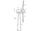
ここで本発明の実施形態を図1から図7を参照して説明する。図1は風車1を概略的に示している。風車1は、タワー2と、ナセル3と、ハブ4とを有している。ナセル3はタワー2の上部に配置されている。ハブ4は、多数の風車羽根5を有している。ハブ4はナセル3に取り付けられている。さらに、ハブ4は、回転軸線9を中心にして回転することができるように取り付けられている。発電機6はナセル3の内部に配置されている。風車1は直接駆動風車である。発電機6は、ハブ4に面した近位側19と、ハブ4とは反対側の遠位側20とを有している。
An embodiment of the present invention will now be described with reference to FIGS. FIG. 1 schematically shows a windmill 1. The windmill 1 includes a tower 2, a nacelle 3, and a hub 4. The nacelle 3 is disposed on the top of the tower 2. The hub 4 has a large number of
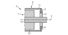
図2は、外側ロータ構成を備えた発電機6の一部を断面図で概略的に示している。発電機6は、ステータアセンブリ7と、ロータアセンブリ8とを有している。ステータアセンブリ7は、回転軸線9の近くに配置された定置の軸10を有している。ロータアセンブリ8は、ステータアセンブリ7の半径方向外側に配置された外側ロータ部分11を有している。ロータアセンブリ8は、さらにブレーキディスク12を有している。ブレーキディスク12は、外側ロータ部分11の一部であるか、外側ロータ部分11に結合されていてよい。ブレーキディスク12は、外側部分11から回転軸線9に向かって半径方向内方へ延びている。ロータアセンブリ8の外側部分11と、ブレーキディスク12とは、回転軸線9を中心に回転可能に取り付けられている。
FIG. 2 schematically shows part of a
ステータアセンブリ7はさらに、摩擦部材、この実施形態においてはブレーキキャリパシステム13を有している。ブレーキキャリパシステム13は、少なくともブレーキディスク12の一部に係合して摩擦を生じるように作用的に構成されている。ブレーキキャリパシステム13は、定置の軸10からブレーキディスク12に向かって半径方向外方へ延びている。ブレーキキャリパシステム13は、ブレーキディスク12を包囲するように、ブレーキディスク12のそれぞれの側において少なくとも1つのブレーキキャリパを有している。
The stator assembly 7 further comprises a friction member, in this embodiment a
ブレーキディスク12とブレーキキャリパシステム13との間の半径距離22は、外側ロータ部分11とステータアセンブリ7との間の半径距離23(空隙)よりも小さい。有利には、半径距離22は、1mm〜5mm、好適には2mm〜4mmである。好適には、空隙23は、4mm〜10mm、有利には5mm〜7mmの幅を有している。
The
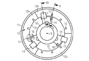
図3は、発電機6の本発明によるブレーキシステムの正面図を示している。前述の図面のエレメントに対応するエレメントは、同じ参照符号で示されており、改めて詳細に説明しない。ブレーキディスク12は内面21を有している。ブレーキディスク12の内面12は、多数の凹所(切欠き)15を有している。好適には、凹所15は、内面21において、半径方向に及び/又は対称に間隔を置いて配置されている。
FIG. 3 shows a front view of the braking system according to the invention of the
概して、ブレーキディスク12は、半径セグメント12a,12b,12cに分割されている。ブレーキディスク12は、その他のあらゆる数の半径セグメントに分割することもできる。これにより、大きなブレーキディスク12を容易に交換することができる。
Generally, the
ブレーキシステムはさらに、多数の中央取付けフランジ14、この実施形態においては3つの中央取付けフランジ14を有している。フランジ14は、定置の軸10に取り付けられている。フランジ14は、定置の軸10の円周に関して120゜の角度でずらされている。択一的に、その他のあらゆる数のフランジ14が可能である。好適には、フランジ14は、互いに隣接するフランジが互いに等しい距離を有するように、定置の軸10の円周の周囲に配置されている。
The brake system further has a number of central mounting
ブレーキシステムは少なくとも1つのロータロックシステム17を有している。ロータロックシステム17は少なくとも1つのピストン16を有している。ピストンは、フランジ14の内部に配置されているか、ロックケーシングの内部に配置されている。ロックケーシングはフランジ14に結合することができる。択一的に、ブレーキシステムは、ピストンを収容するための又はロータロックシステム17の少なくとも1つのロックケーシングに結合されるための別個のフランジを有することができ、別個のフランジ14は、ブレーキシステム、特にブレーキキャリパシステム13と結合されている。
The brake system has at least one
ピストン16は、ブレーキディスク12の内面21に設けられた凹所15と係合するように配置されている。好適には、ロータロックシステム17は自動アクチュエータを有している。自動アクチュエータは、ロータロックを作動させるように構成されていてよい。特に、ロータロックシステム17は、ピストン16を対応する凹所15に押し込むための自動アクチュエータを有していてよい。好適には、アクチュエータは、液圧式手段又は電気的手段、例えば液圧式シリンダを含む。凹所の代わりに、ブレーキディスク12に穴を設けることができ、ピストンの代わりにピンを使用してもよい。
The
多数のピストン16を有する前述のロータロックシステム17の代わりに、インターロック、スナップインロック、ブロック、アレスト、バリケード、又は同様の手段を含むロックシステムを使用してもよい。
Instead of the aforementioned
図4は、本発明によるブレーキシステムの一部を図3のIV−IV線に沿った断面図で概略的に示している。図4において、ブレーキディスク12のそれぞれの側に、2つのブレーキキャリパ13a及び13bが、互いに向き合って配置されている。2つのブレーキキャリパ13a及び13bは、中央取付けフランジ14に結合されている。フランジ14は定置の軸10に結合されている。図4において、ブレーキディスクは外側ロータ部分11の一体化された部分である。択一的に、ブレーキディスク12は、外側ロータ部分11に結合された別個のエレメントであってもよい。例えば、ブレーキディスク12は、例えばボルト又はねじによってロータ支持体のフランジに固定することができる。
FIG. 4 schematically shows a part of the brake system according to the invention in a sectional view along the line IV-IV in FIG. In FIG. 4, two
ブレーキキャリパ13a及び13bを作動させるための作動力は、矢印18によって示されている。ブレーキキャリパ13a及び13bが作動させられると、ブレーキキャリパは、ブレーキディスク12の一部に係合して摩擦を生ずる。
The actuation force for actuating the
風車1は、ベッドフレーム又はステータの支持構造を有していてよい。この場合、ブレーキキャリパシステム13は、風車1のベッドフレーム又はステータの支持構造に直接に取り付けることができる。
The windmill 1 may have a bed frame or stator support structure. In this case, the
図5及び図6は、本発明によるブレーキシステムの一部を図3のV−V線に沿った断面において概略的に示している。この実施形態において、ロータロックシステム17はブレーキシステムに一体化されている。図5は、ロックされていない状態におけるロータロックシステムを示している。図6は、ロックされた状態におけるロータロックシステムを示している。図5において、ピストン16は、フランジ14の内部又はロータロックシステム17の別の構成部材、例えばロックケーシングの内部に完全に配置されている。図6において、ピストン16はブレーキディスク12の対応する凹所15に押し込まれている。この位置において、ロータは停止位置にロックされている。ピストン16を、液圧式手段又は電気的手段によってブレーキディスク12の対応する凹所15へ押し込むことができる。
5 and 6 schematically show a part of the braking system according to the invention in a section along the line V-V in FIG. In this embodiment, the
好適には、本発明によるブレーキシステムは、ハブ4とは反対側の発電機6の遠位側に配置されている。これにより、特にメンテナンス及び保守のための、ブレーキシステム及び一体化されたロータロックシステムへの容易なアクセスが提供される。択一的に、本発明によるブレーキシステムはハブに配置されてよい。例えば、本発明によるブレーキシステムはハブに直接に結合されてよい。
Preferably, the braking system according to the invention is arranged on the distal side of the
図7は、本発明による風車301の一部を概略的に示している。風車は、典型的な公知の「一軸受」配列を有している。風車301は、風車301のタワー303の上流側に配置された直接駆動発電機302を有している。
FIG. 7 schematically shows a part of a
タワーフランジ304はタワー303の上部に配置されている。台板305はタワーフランジ304に取り付けられている。風車401は、風車301の台板305を軸線300を中心にして回転させるために使用されるヨーシステム(図示せず)を有している。
The
風車301は、定置の軸306を有しており、軸306は中心軸線200を有している。定置の軸306の後側は、保持装置307に取り付けられている。定置の軸306の前側には、直接駆動発電機302のステータ装置308が配置されている。ステータ装置308は、ステータ支持構造309と、積層板310とを有している。積層板310は巻線311を支持している。
The
ステータ支持構造309は、積層板310の2側支持のための2つの支持エレメント312を有している。支持エレメント312は環状である。支持エレメント312は、定置の軸306の外側に取り付けられている。中空円筒状の支持エレメント313は、環状の支持エレメント312の外端に取り付けられている。中空円筒状の支持エレメント313は、環状の積層板310と、巻線311とを支持している。
The
ロータ装置314は、ステータ装置308の周囲に配置されている。ロータ装置314は、前側端板315と、円筒エレメント317とを有している。前側端板315は環状であり、円筒エレメント317は中空である。
The
円筒エレメント317は、中空の円筒エレメント317の内側に取り付けられた複数の永久磁石318を有している。永久磁石318は、積層板310及び支持された巻線と向き合って配置されている。約6mmの幅を備えた空隙319は、永久磁石318と積層板310との間に配置されている。好適には、空隙319は、4mm〜10mm、有利には5mm〜7mmの幅を有している。ブレーキディスク12は、ロータの円筒エレメント317に結合されている。ブレーキキャリパシステム13は、定置の軸306に結合されている。ブレーキキャリパシステム13とブレーキディスク12との間の半径距離22は、空隙319よりも小さい。有利には、半径距離22は、1mm〜5mm、好適には2mm〜4mmである。
The
前側端板315は、軸受320を介して定置の軸306に配置されている。軸受320は、中心軸線Aの両方向の軸方向荷重を変換することができる。適切な軸受は、例えば独国実用新案第20116649号明細書に開示されている。
The
軸受320の定置部分321は定置の軸306に取り付けられている。軸受320の回転部分322は取付けリング323に結合されている。前側端板315及びハブ324は取付けリング323に取り付けられている。ハブ324は、風車ロータ羽根(図示せず)のための取付け装置325を有している。
The
ここで示された空隙319は、ロータのエレメントとステータのエレメントとの間の一定の距離を達成するために均一である。一軸受構成は、容易な構成により極めて魅力的である。
The
1 風車、 2 タワー、 3 ナセル、 4 ハブ、 5 風車羽根、 6 発電機、 7 ステータアセンブリ、 8 ロータアセンブリ、 9 回転軸線、 10 定置の軸、 11 外側ロータ部分、 12 ブレーキディスク、 12a,12b,12c 半径セグメント、 13 ブレーキキャリパシステム、 13a,13b ブレーキキャリパ、 14 中央取付けフランジ、 15 凹所、 16 ピストン、 17 ロータロックシステム、 19 近位側、 20 遠位側、 21 内面、 22 半径距離、 23 空隙、 301 風車、 302 直接駆動発電機、 303 タワー、 304 タワーフランジ、 305 台板、 306 軸、 307 保持装置、 308 ステータ装置、 309 ステータ支持構造、 310 積層板、 311 巻線、 312 環状の支持エレメント、 313 中空円筒状の支持エレメント、 314 ロータ装置、 315 前側端板、 317 円筒エレメント、 318 永久磁石、 319 空隙、 320 軸受、 321 定置部分、 322 回転部分、 323 取付けリング、 324 ハブ、 325取付け装置 DESCRIPTION OF SYMBOLS 1 Windmill, 2 Tower, 3 Nacelle, 4 Hub, 5 Windmill blade, 6 Generator, 7 Stator assembly, 8 Rotor assembly, 9 Rotating axis, 10 Stationary shaft, 11 Outer rotor part, 12 Brake disk, 12a, 12b, 12c radius segment, 13 brake caliper system, 13a, 13b brake caliper, 14 central mounting flange, 15 recess, 16 piston, 17 rotor locking system, 19 proximal side, 20 distal side, 21 inner surface, 22 radial distance, 23 Air gap, 301 windmill, 302 direct drive generator, 303 tower, 304 tower flange, 305 base plate, 306 shaft, 307 holding device, 308 stator device, 309 stator support structure, 310 laminated plate, 311 winding 312 annular support element, 313 hollow cylindrical support element, 314 rotor device, 315 front end plate, 317 cylindrical element, 318 permanent magnet, 319 gap, 320 bearing, 321 stationary part, 322 rotating part, 323 mounting ring, 324 hub, 325 mounting device
Claims (17)
ロータアセンブリ(8)が、ステータアセンブリ(7)の半径方向外側に配置された外側部分(11)を有しており、該外側部分(11)がブレーキディスク(12)を有しており、ステータアセンブリ(7)が、ブレーキディスク(12)の少なくとも一部と係合して摩擦を生ずるように作用的に構成された少なくとも1つの摩擦部材(13)を有することを特徴とする、風車の発電機ためのブレーキシステム。 In the braking system for the generator (6) of the windmill (1), the generator (6) has a rotor assembly (8), a stator assembly (7), and a rotation axis (9). ,
The rotor assembly (8) has an outer portion (11) disposed radially outward of the stator assembly (7), the outer portion (11) having a brake disc (12), and the stator Wind turbine power generation , characterized in that the assembly (7) has at least one friction member (13) operatively configured to engage and generate friction with at least a portion of the brake disc (12) Brake system for the machine .
Applications Claiming Priority (2)
| Application Number | Priority Date | Filing Date | Title |
|---|---|---|---|
| EP09014766.1 | 2009-11-26 | ||
| EP09014766.1A EP2333325B1 (en) | 2009-11-26 | 2009-11-26 | Brake system, generator and wind turbine |
Publications (3)
| Publication Number | Publication Date |
|---|---|
| JP2011112227A JP2011112227A (en) | 2011-06-09 |
| JP2011112227A5 JP2011112227A5 (en) | 2013-09-12 |
| JP5717413B2 true JP5717413B2 (en) | 2015-05-13 |
Family
ID=42634903
Family Applications (1)
| Application Number | Title | Priority Date | Filing Date |
|---|---|---|---|
| JP2010263889A Active JP5717413B2 (en) | 2009-11-26 | 2010-11-26 | Brake system, generator, and windmill |
Country Status (7)
| Country | Link |
|---|---|
| US (1) | US9906099B2 (en) |
| EP (1) | EP2333325B1 (en) |
| JP (1) | JP5717413B2 (en) |
| CN (1) | CN102080630B (en) |
| CA (1) | CA2722501C (en) |
| DK (1) | DK2333325T3 (en) |
| NZ (1) | NZ589529A (en) |
Families Citing this family (19)
| Publication number | Priority date | Publication date | Assignee | Title |
|---|---|---|---|---|
| GB2461285B (en) * | 2008-06-26 | 2012-07-25 | Converteam Technology Ltd | Vertical axis wind turbines |
| CN101482097B (en) * | 2009-01-21 | 2012-01-25 | 严强 | Braking system and braking method used for vertical axis aerogenerator |
| EP2437380A1 (en) * | 2010-09-30 | 2012-04-04 | Siemens Aktiengesellschaft | Rotor, generator and wind turbine |
| EP2661553B1 (en) * | 2011-01-05 | 2017-09-27 | Vestas Wind Systems A/S | A direct drive generator |
| EP2584673A1 (en) * | 2011-10-17 | 2013-04-24 | ABB Oy | Electric machine with dampening means |
| DE102012208550A1 (en) * | 2012-05-22 | 2013-11-28 | Wobben Properties Gmbh | Generator of a gearless wind turbine |
| DK2669510T3 (en) * | 2012-05-30 | 2014-10-06 | Siemens Ag | Brake system for a wind turbine |
| EP2690284B1 (en) * | 2012-07-23 | 2015-08-26 | Siemens Aktiengesellschaft | Wind turbine generator and maintenance of its main bearing |
| DE102012215575A1 (en) | 2012-09-03 | 2014-03-06 | Wobben Properties Gmbh | Method and control device for a wind energy plant and computer program product, digital storage medium and wind energy plant |
| EP2747252B1 (en) * | 2012-12-18 | 2019-01-23 | Siemens Aktiengesellschaft | Air-gap secure system for a wind turbine |
| DE102013004580A1 (en) | 2013-03-18 | 2014-09-18 | Wind-Direct Gmbh | Method for locking a wind turbine and wind turbine for carrying out the method |
| RU2015149805A (en) * | 2013-04-23 | 2017-05-26 | Ювинэнерджи Гмбх | WIND TURBINE DESIGN |
| DK2896824T3 (en) * | 2014-01-20 | 2016-08-29 | Siemens Ag | Brake system for a wind turbine generator |
| KR101763641B1 (en) * | 2016-01-05 | 2017-08-01 | 손정봉 | Wind power generator |
| DE102018100864A1 (en) | 2018-01-16 | 2019-07-18 | Wobben Properties Gmbh | Wind turbine with a braking and locking device, stand assembly for selbige, and method for their operation |
| CN110195685B (en) * | 2019-05-27 | 2020-11-27 | 上海电气风电集团股份有限公司 | Brake system and outer rotor type direct-drive wind generating set |
| CN110425235A (en) * | 2019-08-29 | 2019-11-08 | 中国华能集团清洁能源技术研究院有限公司 | A kind of wind-driven generator braking device |
| CN112664392A (en) | 2019-10-15 | 2021-04-16 | 通用电气公司 | System and method for locking wind turbine rotor during extended maintenance |
| CN113217284B (en) * | 2021-05-17 | 2022-07-22 | 广州赛特新能源科技发展有限公司 | Direct-drive breeze wind driven generator system |
Family Cites Families (20)
| Publication number | Priority date | Publication date | Assignee | Title |
|---|---|---|---|---|
| US3718210A (en) * | 1970-06-24 | 1973-02-27 | Goodyear Tire & Rubber | Rotating brake disc subassembly with segmented beryllium core |
| JPS6381338U (en) | 1986-11-17 | 1988-05-28 | ||
| JPH08200203A (en) * | 1995-01-25 | 1996-08-06 | Mitsubishi Heavy Ind Ltd | Windmill speed-increasing gear protection device |
| JPH10184740A (en) | 1996-12-18 | 1998-07-14 | Akebono Brake Ind Co Ltd | Twin-caliper type disk brake device |
| FR2810374B1 (en) * | 2000-06-19 | 2004-09-03 | Jeumont Ind | DEVICE FOR PRODUCING ELECTRIC CURRENT FROM WIND ENERGY |
| CA2369229A1 (en) * | 2002-01-24 | 2003-07-24 | Jacquelin Dery | Vertical axis windmill and self-erecting structure therefor |
| US6749399B2 (en) | 2002-03-07 | 2004-06-15 | Ocean Wind Energy Systems | Vertical array wind turbine |
| US7042109B2 (en) * | 2002-08-30 | 2006-05-09 | Gabrys Christopher W | Wind turbine |
| JP2004312845A (en) | 2003-04-04 | 2004-11-04 | Nissan Motor Co Ltd | Stator for motor |
| US7431567B1 (en) | 2003-05-30 | 2008-10-07 | Northern Power Systems Inc. | Wind turbine having a direct-drive drivetrain |
| US7075192B2 (en) | 2004-04-19 | 2006-07-11 | Northern Power Systems, Inc. | Direct drive wind turbine |
| JP4391884B2 (en) | 2004-05-26 | 2009-12-24 | 本田技研工業株式会社 | Wheel drive device for vehicle |
| US7467530B2 (en) * | 2005-07-29 | 2008-12-23 | New Hampton Technologies Llc | Vehicle lock |
| JP2007211875A (en) | 2006-02-09 | 2007-08-23 | Hino Motors Ltd | Parking braking device of disc brake vehicle |
| EP2327873A1 (en) * | 2006-04-28 | 2011-06-01 | Swanturbines Limited | Tidal current turbine |
| US7431557B2 (en) * | 2006-05-25 | 2008-10-07 | General Electric Company | Compensating for blade tip clearance deterioration in active clearance control |
| JP5110854B2 (en) | 2006-11-17 | 2012-12-26 | Ntn株式会社 | Wheel bearing device with in-wheel motor built-in sensor |
| DE602006018029D1 (en) * | 2006-11-23 | 2010-12-16 | Stx Heavy Ind Co Ltd | Main warehouse of a wind turbine |
| US7821164B2 (en) * | 2007-02-15 | 2010-10-26 | General Electric Company | Method and apparatus for a superconducting generator driven by wind turbine |
| JP5045140B2 (en) | 2007-02-19 | 2012-10-10 | 澁谷工業株式会社 | Electron beam sterilization system |
-
2009
- 2009-11-26 EP EP09014766.1A patent/EP2333325B1/en active Active
- 2009-11-26 DK DK09014766.1T patent/DK2333325T3/en active
-
2010
- 2010-11-22 US US12/951,414 patent/US9906099B2/en active Active
- 2010-11-24 CA CA2722501A patent/CA2722501C/en not_active Expired - Fee Related
- 2010-11-25 NZ NZ589529A patent/NZ589529A/en not_active IP Right Cessation
- 2010-11-26 JP JP2010263889A patent/JP5717413B2/en active Active
- 2010-11-26 CN CN201010565611.2A patent/CN102080630B/en active Active
Also Published As
| Publication number | Publication date |
|---|---|
| CN102080630B (en) | 2014-11-26 |
| EP2333325A1 (en) | 2011-06-15 |
| JP2011112227A (en) | 2011-06-09 |
| NZ589529A (en) | 2011-07-29 |
| CA2722501C (en) | 2018-10-16 |
| DK2333325T3 (en) | 2015-08-24 |
| CA2722501A1 (en) | 2011-05-26 |
| US20110121579A1 (en) | 2011-05-26 |
| US9906099B2 (en) | 2018-02-27 |
| EP2333325B1 (en) | 2015-06-24 |
| CN102080630A (en) | 2011-06-01 |
Similar Documents
| Publication | Publication Date | Title |
|---|---|---|
| JP5773621B2 (en) | Brake system, generator, and windmill for windmill with integrated rotor lock | |
| JP5717413B2 (en) | Brake system, generator, and windmill | |
| CA2882094C (en) | Wind-driven generator and impeller locking device for wind-driven generator | |
| EP2143936B1 (en) | Wind turbine comprising a main bearing and method for replacement of the main bearing | |
| US10454342B2 (en) | Rotational movement control of an electric generator by means of a turning device | |
| JP2011112055A5 (en) | ||
| JP2011112227A5 (en) | ||
| US20140147279A1 (en) | Brake system with expansion absorbing means, generator and wind turbine | |
| US11111902B2 (en) | Nacelle and rotor for a wind turbine, and method | |
| EP2896824B1 (en) | Brake system for a wind turbine generator | |
| EP3226384A1 (en) | Rotational movement control of an electric generator by means of a turning device | |
| US20190195197A1 (en) | Rotor arresting device for a wind turbine and method | |
| EP4156475A1 (en) | Rotor lock for an electrical machine |
Legal Events
| Date | Code | Title | Description |
|---|---|---|---|
| A521 | Request for written amendment filed |
Free format text: JAPANESE INTERMEDIATE CODE: A523 Effective date: 20130802 |
|
| A621 | Written request for application examination |
Free format text: JAPANESE INTERMEDIATE CODE: A621 Effective date: 20130802 |
|
| A977 | Report on retrieval |
Free format text: JAPANESE INTERMEDIATE CODE: A971007 Effective date: 20140326 |
|
| A131 | Notification of reasons for refusal |
Free format text: JAPANESE INTERMEDIATE CODE: A131 Effective date: 20140407 |
|
| A601 | Written request for extension of time |
Free format text: JAPANESE INTERMEDIATE CODE: A601 Effective date: 20140707 |
|
| A602 | Written permission of extension of time |
Free format text: JAPANESE INTERMEDIATE CODE: A602 Effective date: 20140710 |
|
| A601 | Written request for extension of time |
Free format text: JAPANESE INTERMEDIATE CODE: A601 Effective date: 20140807 |
|
| A602 | Written permission of extension of time |
Free format text: JAPANESE INTERMEDIATE CODE: A602 Effective date: 20140812 |
|
| A521 | Request for written amendment filed |
Free format text: JAPANESE INTERMEDIATE CODE: A523 Effective date: 20140905 |
|
| TRDD | Decision of grant or rejection written | ||
| A01 | Written decision to grant a patent or to grant a registration (utility model) |
Free format text: JAPANESE INTERMEDIATE CODE: A01 Effective date: 20150216 |
|
| A61 | First payment of annual fees (during grant procedure) |
Free format text: JAPANESE INTERMEDIATE CODE: A61 Effective date: 20150317 |
|
| R150 | Certificate of patent or registration of utility model |
Ref document number: 5717413 Country of ref document: JP Free format text: JAPANESE INTERMEDIATE CODE: R150 |
|
| R250 | Receipt of annual fees |
Free format text: JAPANESE INTERMEDIATE CODE: R250 |
|
| R250 | Receipt of annual fees |
Free format text: JAPANESE INTERMEDIATE CODE: R250 |
|
| R250 | Receipt of annual fees |
Free format text: JAPANESE INTERMEDIATE CODE: R250 |
|
| S111 | Request for change of ownership or part of ownership |
Free format text: JAPANESE INTERMEDIATE CODE: R313113 |
|
| S531 | Written request for registration of change of domicile |
Free format text: JAPANESE INTERMEDIATE CODE: R313531 |
|
| R350 | Written notification of registration of transfer |
Free format text: JAPANESE INTERMEDIATE CODE: R350 |
|
| R250 | Receipt of annual fees |
Free format text: JAPANESE INTERMEDIATE CODE: R250 |
|
| R250 | Receipt of annual fees |
Free format text: JAPANESE INTERMEDIATE CODE: R250 |
|
| R250 | Receipt of annual fees |
Free format text: JAPANESE INTERMEDIATE CODE: R250 |