JP5716634B2 - Control device for hybrid vehicle - Google Patents
Control device for hybrid vehicle Download PDFInfo
- Publication number
- JP5716634B2 JP5716634B2 JP2011236198A JP2011236198A JP5716634B2 JP 5716634 B2 JP5716634 B2 JP 5716634B2 JP 2011236198 A JP2011236198 A JP 2011236198A JP 2011236198 A JP2011236198 A JP 2011236198A JP 5716634 B2 JP5716634 B2 JP 5716634B2
- Authority
- JP
- Japan
- Prior art keywords
- torque
- parking
- electric motor
- engine
- hybrid vehicle
- Prior art date
- Legal status (The legal status is an assumption and is not a legal conclusion. Google has not performed a legal analysis and makes no representation as to the accuracy of the status listed.)
- Active
Links
Images

Classifications
-
- Y—GENERAL TAGGING OF NEW TECHNOLOGICAL DEVELOPMENTS; GENERAL TAGGING OF CROSS-SECTIONAL TECHNOLOGIES SPANNING OVER SEVERAL SECTIONS OF THE IPC; TECHNICAL SUBJECTS COVERED BY FORMER USPC CROSS-REFERENCE ART COLLECTIONS [XRACs] AND DIGESTS
- Y02—TECHNOLOGIES OR APPLICATIONS FOR MITIGATION OR ADAPTATION AGAINST CLIMATE CHANGE
- Y02T—CLIMATE CHANGE MITIGATION TECHNOLOGIES RELATED TO TRANSPORTATION
- Y02T10/00—Road transport of goods or passengers
- Y02T10/60—Other road transportation technologies with climate change mitigation effect
- Y02T10/62—Hybrid vehicles
Landscapes
- Hybrid Electric Vehicles (AREA)
- Control Of Vehicle Engines Or Engines For Specific Uses (AREA)
- Electric Propulsion And Braking For Vehicles (AREA)
Description
本発明は、走行用駆動力源として内燃機関と電動機とが搭載されたハイブリッド車両の制御装置に係る。特に、本発明は、動力伝達系において発生する異音を低減または防止するための制御の改良に関する。 The present invention relates to a control apparatus for a hybrid vehicle in which an internal combustion engine and an electric motor are mounted as driving power sources for traveling. In particular, the present invention relates to an improvement in control for reducing or preventing abnormal noise generated in a power transmission system.
下記の特許文献1〜特許文献3に開示されているように、ハイブリッド車両は、ガソリンエンジンやディーゼルエンジン等のエンジン(内燃機関)と、このエンジンの出力により発電された電力やバッテリ(蓄電装置)に蓄えられた電力により駆動する電動機(例えばモータジェネレータまたはモータ)とを備え、これらエンジン及び電動機のいずれか一方または双方を走行用駆動力源として利用しながら走行する。
As disclosed in
この種のハイブリッド車両に採用されるパワートレーンとして、エンジン、第1及び第2の電動機(モータジェネレータ)、動力分割機構を構成する遊星歯車機構を備えたものが知られている。具体的には、動力分割機構のプラネタリキャリアにエンジンのクランクシャフトが連結され、サンギヤに第1電動機(第1モータジェネレータMG1)が連結され、リングギヤにリダクション機構(例えば遊星歯車機構により構成されている)を介して第2電動機(第2モータジェネレータMG2)が連結されている。そして、このリングギヤには、減速機構やデファレンシャルギヤを介して駆動輪が動力伝達可能に連結されている。 As a power train employed in this type of hybrid vehicle, an engine, first and second electric motors (motor generators), and a planetary gear mechanism that constitutes a power split mechanism are known. Specifically, the engine crankshaft is connected to the planetary carrier of the power split mechanism, the first electric motor (first motor generator MG1) is connected to the sun gear, and the reduction gear (for example, a planetary gear mechanism) is configured to the ring gear. ) Is connected to the second electric motor (second motor generator MG2). The drive gear is connected to the ring gear through a reduction mechanism and a differential gear so that power can be transmitted.
この種のハイブリッド車両では、エンジン始動要求時、第1電動機をスタータモータとして機能させ、この第1電動機の回転力を、動力分割機構を介してエンジンのクランクシャフトに伝達することによってエンジンのクランキングを行うようにしている。 In this type of hybrid vehicle, when the engine is requested to start, the first electric motor functions as a starter motor, and the rotational force of the first electric motor is transmitted to the crankshaft of the engine via the power split mechanism to thereby crank the engine. Like to do.
また、この種のハイブリッド車両では、上記減速機構にパーキングロック機構が設けられており、運転者によってシフトレバーがPレンジに操作されている(Pスイッチを備えた車両の場合にはPスイッチが押し込み操作されている)場合には、このパーキングロック機構が作動して駆動輪の回転を禁止するようになっている。具体的には、上記減速機構に回転一体に連結されたパーキングギヤに対してパーキングロックポール(以下「Pロックピン」と呼ぶ場合もある)を噛み合わせることで減速機構の回転を阻止し、これによって駆動輪の回転を禁止している。 Further, in this type of hybrid vehicle, the deceleration mechanism is provided with a parking lock mechanism, and the shift lever is operated to the P range by the driver (in the case of a vehicle having a P switch, the P switch is pushed in). In the case of operation), the parking lock mechanism is activated to prohibit the rotation of the drive wheels. Specifically, a parking lock pole (hereinafter also referred to as “P lock pin”) is engaged with a parking gear that is integrally connected to the speed reduction mechanism to prevent the speed reduction mechanism from rotating. This prohibits rotation of the drive wheels.
ところで、上記パーキングロック機構が作動している状態(車両の停車状態)において、車室内の暖房要求やバッテリの充電要求などに応じてエンジンが駆動している場合、上記遊星歯車機構や減速機構等におけるギヤ同士の間に隙間(バックラッシ等)が存在していることに起因し、エンジンのトルク変動の影響によって歯打ち音(「ガラ音」とも呼ばれる)が生じる可能性がある。 By the way, when the parking lock mechanism is in operation (the vehicle is stopped), when the engine is driven in response to a heating request in the passenger compartment or a battery charging request, the planetary gear mechanism, the speed reduction mechanism, or the like. Due to the existence of a gap (backlash or the like) between the gears in the gear, there is a possibility that a rattling sound (also referred to as “gull noise”) is generated due to the influence of engine torque fluctuation.
この歯打ち音の発生を防止する技術として、各特許文献に開示されているように、互いに噛み合っているギヤの一方の歯を他方の歯に押し当てるためのトルク(以下、「押し当てトルク」と呼ぶ)を電動機(例えば上記第2電動機)によって発生させることが知られている。 As a technique for preventing the occurrence of rattling noise, as disclosed in each patent document, torque for pressing one tooth of gears meshing with each other (hereinafter referred to as “pressing torque”). Is called an electric motor (for example, the second electric motor).
この押し当てトルクの制御に関し、特許文献3には、負荷運転と無負荷運転(「自立運転」とも呼ばれる)との間でエンジン運転状態が切り換えられる際に、押し当てトルクの作用方向を切り換え、これによって、歯打ち音を抑制すると共に、パーキングロック機構におけるパーキングギヤに対するパーキングロックポールの噛み合わせを適正に行うことが開示されている。 Regarding the control of the pressing torque, Patent Document 3 discloses that when the engine operating state is switched between a load operation and a no-load operation (also referred to as “self-sustained operation”), the direction in which the pressing torque is applied is changed. Thus, it is disclosed that the rattling noise is suppressed and that the parking lock pole is properly engaged with the parking gear in the parking lock mechanism.
ところが、上記特許文献3に開示されているようにエンジン運転状態が切り換えられる際に押し当てトルクの作用方向を切り換えるものにあっては、その切り換え途中において押し当てトルクが「0」となる状況が生じる。このため、この押し当てトルクが一時的に低くなる期間にあっては押し当てトルクを作用させることの効果、つまり、歯打ち音抑制効果が発揮できなくなる可能性があり、一時的に歯打ち音が発生してしまう可能性がある。 However, in the case of switching the direction of operation of the pressing torque when the engine operating state is switched as disclosed in Patent Document 3, there is a situation in which the pressing torque becomes “0” during the switching. Arise. For this reason, there is a possibility that the effect of applying the pressing torque during the period in which the pressing torque is temporarily reduced, that is, the effect of suppressing the rattling noise may not be exhibited. May occur.
本発明は、かかる点に鑑みてなされたものであり、その目的とするところは、内燃機関の運転状態が切り換えられる際における歯打ち音の発生を防止できるハイブリッド車両の制御装置を提供することにある。 The present invention has been made in view of such points, and an object of the present invention is to provide a control device for a hybrid vehicle that can prevent the occurrence of rattling noise when the operating state of the internal combustion engine is switched. is there.
−発明の概要−
上記の目的を達成するために講じられた本発明の概要は、動力伝達経路における異音(歯打ち音等)の発生を防止するための押し当てトルクの作用方向として、内燃機関が冷間状態にある場合には、内燃機関の運転状態が切り換わったとしても押し当てトルクの作用方向を変更しないようにし、一時的に異音が発生してしまうといった状況を招かないようにしている。
-Summary of invention-
The outline of the present invention taken in order to achieve the above object is that the internal combustion engine is in a cold state as a direction of action of the pressing torque for preventing the occurrence of abnormal noise (tooth rattling noise, etc.) in the power transmission path. In this case, even if the operation state of the internal combustion engine is switched, the direction of operation of the pressing torque is not changed, so that a situation in which abnormal noise is temporarily generated is not caused.
−解決手段−
具体的に、本発明は、走行用駆動力源として内燃機関及び電動機を備え、シフト操作装置の操作状態が駐車ポジションにあり、車両が停車している状態で上記内燃機関が駆動している場合に、上記電動機からのトルクを動力伝達系に与えることによって、この動力伝達系での異音の発生を低減または防止する異音低減制御を実行するハイブリッド車両の制御装置を前提とする。このハイブリッド車両の制御装置に対し、上記内燃機関の温間時には、この内燃機関の運転状態が負荷運転状態と自立運転状態との間で切り換わったことに伴い、上記異音低減制御において上記電動機から上記動力伝達系に与えられる上記トルクの作用方向を切り換える一方、上記内燃機関の冷間時には、この内燃機関の運転状態が上記負荷運転状態と上記自立運転状態との間で切り換わっても上記異音低減制御において上記電動機から上記動力伝達系に与えられる上記トルクの作用方向を一方向に維持する構成としている。
-Solution-
Specifically, the present invention includes an internal combustion engine and an electric motor as driving power sources for travel, the operation state of the shift operation device is in the parking position, and the internal combustion engine is driven in a state where the vehicle is stopped. to, by providing a torque from the electric motor to the power transmission system, assumes control apparatus for a hybrid vehicle that performs the abnormal sound reduction control to reduce or prevent the generation of noise in the power transmission system. To the control device of the hybrid vehicle, at the time of the warm of the internal combustion engine, with the possible operating conditions of the internal combustion engine is switched between the self-sustaining operation condition and the load operating state, the electric motor in the abnormal sound reduction control while switching the direction of action of the torque applied to the power transmission system from the cold state of the internal combustion engine, the even switched operating state of the internal combustion engine is between the load operation state and the self-sustaining operation condition in abnormal sound reduction control is configured to maintain the acting direction of the torque applied to the power transmission system from the electric motor in one direction.
内燃機関の運転状態が変化した場合に、電動機から動力伝達系に与えられるトルク(以下、「押し当てトルク」と呼ぶ)の作用方向を切り換えるものにあっては、その切り換え途中において押し当てトルクが「0」となる状況が生じる。このため、この押し当てトルクが一時的に低くなる期間にあっては押し当てトルクを作用させることの効果、つまり、異音発生抑制効果が発揮できなくなる可能性がある。特に、内燃機関の冷間時には、温間時に比べて内燃機関のトルク変動が大きいため、上記押し当てトルクの作用方向を切り換えることによる上記課題は顕著である。本解決手段では、この課題が顕著に現れる内燃機関の冷間時に、上記異音低減制御において電動機から動力伝達系に与えられるトルクの作用方向を一方向に維持している。このため、押し当てトルクの作用方向の切り換えに伴って押し当てトルクが「0」となる状況は生じず、常に高い押し当てトルクが確保されることになって異音抑制効果を継続的に発揮させることが可能になる。尚、内燃機関の温間時には、異音発生の可能性が冷間時に比べて低いため、内燃機関の運転状態の変化に伴って上記異音低減制御において電動機から動力伝達系に与えられるトルクの作用方向を切り換えることで、上記特許文献3の効果(歯打ち音を抑制すると共に、パーキングロック機構におけるパーキングギヤに対するパーキングロックポールの噛み合わせを適正に行うといった効果)を奏することができる。
また、負荷運転として具体的には、蓄電装置(バッテリ)の残容量(SOC)が所定量未満に達したことで充電要求が生じた場合における内燃機関の運転状態が挙げられる。また、自立運転として具体的には、車室内の暖房要求に応じ、内燃機関を熱源として用いる必要がある場合における内燃機関の運転状態が挙げられる。
When the operating state of the internal combustion engine changes, the switching direction of the torque applied to the power transmission system from the electric motor (hereinafter referred to as “pressing torque”) is changed during the switching. A situation of “0” occurs. For this reason, there is a possibility that the effect of applying the pressing torque, that is, the effect of suppressing the generation of abnormal noise cannot be exhibited during the period in which the pressing torque is temporarily reduced. In particular, since the torque fluctuation of the internal combustion engine is larger when the internal combustion engine is cold than when the internal combustion engine is warm, the above problem caused by switching the direction of action of the pressing torque is significant. In the present solution, when the internal combustion engine is cold when this problem appears remarkably, the direction of the torque applied from the electric motor to the power transmission system in the abnormal noise reduction control is maintained in one direction. For this reason, there is no situation where the pressing torque becomes “0” in accordance with the switching of the direction of operation of the pressing torque, and a high pressing torque is always secured, and the noise suppressing effect is continuously exhibited. It becomes possible to make it. Since the possibility of abnormal noise generation is low when the internal combustion engine is warm compared to when it is cold, the torque applied from the motor to the power transmission system in the abnormal noise reduction control according to the change in the operating state of the internal combustion engine. By switching the direction of action, the effect of Patent Document 3 (the effect of suppressing the rattling noise and appropriately engaging the parking lock pole with the parking gear in the parking lock mechanism) can be achieved.
Further, specific examples of the load operation include an operation state of the internal combustion engine when a charge request is generated because the remaining capacity (SOC) of the power storage device (battery) has reached less than a predetermined amount. In addition, specific examples of the self-sustained operation include an operation state of the internal combustion engine when it is necessary to use the internal combustion engine as a heat source in response to a heating request in the passenger compartment.
上記押し当てトルクの作用方向を一方向に維持する場合における押し当てトルクの大きさとしては、内燃機関の温間時における電動機から動力伝達系に与えられるトルクよりも大きく設定される。 When the operating direction of the pressing torque is maintained in one direction, the magnitude of the pressing torque is set larger than the torque applied from the electric motor to the power transmission system when the internal combustion engine is warm.
これにより、一方向に維持され且つ高い押し当てトルクを得ることができ、互いに噛み合っているギヤの一方の歯を他方の歯に押し当てるトルクを十分に確保できて、内燃機関の運転状態が変化する場合ばかりでなく、内燃機関のトルク変動が生じた場合にも、異音抑制効果を高く維持することが可能になる。 As a result, a high pressing torque that is maintained in one direction can be obtained, a sufficient torque can be secured to press one tooth of the gears meshing with each other, and the operating state of the internal combustion engine changes. This makes it possible to maintain a high noise suppression effect not only when the torque fluctuations of the internal combustion engine occur, but also when the torque fluctuation occurs.
また、上記電動機から動力伝達系に与えられるトルクの作用方向を一方向に維持する制御は、所定の条件が成立した場合に解除または禁止される。 The control for maintaining the direction of the torque applied from the electric motor to the power transmission system in one direction is canceled or prohibited when a predetermined condition is satisfied.
この際の解除条件としては、シフト操作装置がパーキング状態から非パーキング状態に操作された場合に成立する。 The release condition at this time is satisfied when the shift operating device is operated from the parking state to the non-parking state.
つまり、車両が停車状態から走行状態に移る場合、動力伝達系には内燃機関及び電動機からの駆動力が駆動輪に向けて伝達されることになるため押し当てトルクの必要がなくなるので上記押し当てトルクを一方向に維持する制御は解除されることになる。 In other words, when the vehicle moves from the stopped state to the traveling state, the driving force from the internal combustion engine and the electric motor is transmitted to the drive wheels to the power transmission system, so there is no need for the pressing torque. The control for maintaining the torque in one direction is released.
そして、シフト操作装置がパーキングから非パーキングに操作された場合、電動機から動力伝達系に与えられるトルクが所定値に低下するまでは、単位時間当たりのトルク減少量を大きく設定する一方、トルクが所定値に低下した後、単位時間当たりのトルク減少量を小さく設定する。 When the shift operating device is operated from parking to non-parking, the torque reduction amount per unit time is set large until the torque applied from the electric motor to the power transmission system decreases to a predetermined value, while the torque is set to the predetermined value. After decreasing to the value, the amount of torque reduction per unit time is set small.
これによれば、シフト操作装置がパーキング状態にあった際に噛み合っているパーキングギヤとパーキングロックポールとの接触部の強圧状態が早期に解消されることになり、このパーキングロックポールの解除途中での拗り音の発生が回避できる。 According to this, when the shift operating device is in the parking state, the high pressure state of the contact portion between the parking gear and the parking lock pawl is canceled at an early stage. The generation of a roaring sound can be avoided.
また、上記電動機から動力伝達系に与えられるトルクの作用方向を一方向に維持する制御の禁止条件は、車両が停車している路面の勾配が所定勾配を超えている場合に成立する。 Further, the control prohibition condition for maintaining the direction of the torque applied from the electric motor to the power transmission system in one direction is satisfied when the gradient of the road surface on which the vehicle is stopped exceeds a predetermined gradient.
この場合、パーキングギヤに対してパーキングロックポールを噛み合わせることにより駆動輪を停止させるパーキングロック機構を備えており、上記電動機から動力伝達系に与えられるトルクの作用方向を一方向に維持する制御の禁止条件は、パーキングギヤに対してパーキングロックポールが噛み合っていない状態から噛み合い可能な位置までパーキングギヤが回転した際におけるパーキングギヤの回転速度がパーキングロックポールの噛み合いが不能な所定速度以上になる車速となる路面勾配を超えている場合に成立する。 In this case, a parking lock mechanism for stopping the drive wheel by engaging the parking lock pole with the parking gear is provided, and the control direction of the torque applied from the motor to the power transmission system is maintained in one direction. The prohibition condition is that the speed at which the parking gear rotates when the parking gear rotates from a state where the parking lock pole does not mesh with the parking gear to a position where it can be meshed becomes a predetermined speed at which the parking lock pole cannot mesh. It is established when the road surface gradient is exceeded.
これにより、押し当てトルクを増大させたことに起因してパーキングギヤに対するパーキングロックポールの噛み合わせが不能になるといった状況を回避することができ、仮にシフト操作装置がパーキング状態となった時点でパーキングロックポールがパーキングギヤに噛み合っていなかった場合であっても、路面勾配に従って車両が僅かに移動し、それに伴ってパーキングギヤが回転した際には、その回転速度を低くできて、パーキングロックポールをパーキングギヤに噛み合わせることが可能になる。 As a result, it is possible to avoid a situation in which the engagement of the parking lock pole with the parking gear due to an increase in the pressing torque is disabled, and the parking operation is performed when the shift operation device is in the parking state. Even when the lock pawl is not engaged with the parking gear, if the vehicle moves slightly according to the road surface gradient and the parking gear rotates accordingly, the rotation speed can be lowered, and the parking lock pawl can be It becomes possible to mesh with the parking gear.
また、上記走行用駆動力源からの駆動力を受ける駆動輪に、この駆動輪の回転を阻止する制動力を発生するブレーキ装置が設けられている場合に、上記電動機から動力伝達系に与えられるトルクの作用方向を一方向に維持する制御の実行時において、電動機から動力伝達系に与えられるトルクの大きさが変化しても、ブレーキ装置による駆動輪への制動力を一定に維持するようにしている。 In addition, when the driving wheel that receives the driving force from the driving power source for traveling is provided with a braking device that generates a braking force that prevents rotation of the driving wheel, the motor is applied to the power transmission system. When executing the control to maintain the direction of the torque in one direction, the braking force applied to the drive wheels by the brake device is kept constant even if the magnitude of the torque applied from the motor to the power transmission system changes. ing.
一般にブレーキ装置には油圧制御バルブ等の機器が設けられており、電動機から動力伝達系に与えられるトルクの大きさの変化に応じて油圧制御バルブを制御して駆動輪への制動力を変化させるようにした場合には、油圧制御バルブの耐久性に悪影響を与えてしまう可能性がある。このことを考慮し、電動機から動力伝達系に与えられるトルクの大きさが変化しても、ブレーキ装置による駆動輪への制動力を一定に維持し、これによってブレーキ装置を構成する部品(油圧制御バルブ等)の耐久性の向上を図っている。 In general, a brake device is provided with a device such as a hydraulic control valve, and controls the hydraulic control valve according to a change in the magnitude of torque applied from the electric motor to the power transmission system to change the braking force to the drive wheel. In such a case, the durability of the hydraulic control valve may be adversely affected. Considering this, even if the magnitude of torque applied from the electric motor to the power transmission system changes, the braking force applied to the drive wheels by the brake device is kept constant, and the components that make up the brake device (hydraulic control) The durability of valves, etc.) is improved.
また、ハイブリッド車両の動力伝達経路の構成として具体的には、上記内燃機関の出力軸が連結されるプラネタリキャリアと、第1の電動機が連結されるサンギヤと、第2の電動機が連結されるリングギヤとを備えた遊星歯車機構により構成される動力分割機構を備えており、異音低減制御では、第2の電動機からのトルクにより動力伝達系での異音の発生を低減または防止する構成となっている。 Further, as a configuration of the power transmission path of the hybrid vehicle, specifically, a planetary carrier to which the output shaft of the internal combustion engine is connected, a sun gear to which the first electric motor is connected, and a ring gear to which the second electric motor is connected. In the abnormal noise reduction control, the generation of abnormal noise in the power transmission system is reduced or prevented by the torque from the second motor. ing.
本発明では、動力伝達経路における異音の発生を防止するための押し当てトルクの作用方向として、内燃機関の冷間時には、内燃機関の運転状態が変化しても押し当てトルクの作用方向を変更しないようにしている。これにより、常に高い押し当てトルクが確保されることになって異音抑制効果を継続的に発揮させることが可能になる。 In the present invention, as the direction of operation of the pressing torque for preventing the generation of abnormal noise in the power transmission path, when the internal combustion engine is cold, the direction of operation of the pressing torque is changed even if the operating state of the internal combustion engine changes. I try not to. Thereby, a high pressing torque is always ensured, and it becomes possible to continuously exhibit the noise suppression effect.
以下、本発明の実施の形態を図面に基づいて説明する。本実施形態では、FF(フロントエンジン・フロントドライブ)方式のハイブリッド車両に本発明を適用した場合について説明する。 Hereinafter, embodiments of the present invention will be described with reference to the drawings. In the present embodiment, a case where the present invention is applied to an FF (front engine / front drive) type hybrid vehicle will be described.
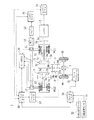
図1は本実施形態に係るハイブリッド車両1を示す概略構成図である。この図1に示すように、ハイブリッド車両1は、前輪(駆動輪)6a,6bに駆動力を与えるための駆動系(動力伝達系)として、エンジン2と、エンジン2の出力軸としてのクランクシャフト2aにダンパ2bを介して接続された3軸式の動力分割機構3と、この動力分割機構3に接続された発電可能な第1モータジェネレータMG1と、動力分割機構3に接続された駆動軸としてのリングギヤ軸3eにリダクション機構7を介して接続された第2モータジェネレータMG2とを備えている。また、上記リングギヤ軸3eは、ギヤ機構4及び前輪用のデファレンシャルギヤ5を介して前輪6a,6bに接続されている。
FIG. 1 is a schematic configuration diagram showing a
また、このハイブリッド車両1は、車両の駆動系全体をコントロールするハイブリッド用電子制御ユニット(以下、ハイブリッドECU(Electronic Control Unit)という)10を備えている。
The
上記エンジン2は、ガソリンまたは軽油などの炭化水素系の燃料により動力を出力する内燃機関であり、エンジン2の運転状態を検出する各種センサから信号を入力するエンジン用電子制御ユニット(以下、エンジンECUという)11により、燃料噴射制御、点火制御、吸入空気量調節制御などの運転制御が行われる。エンジンECU11は、上記ハイブリッドECU10と通信しており、このハイブリッドECU10からの制御信号によりエンジン2を運転制御すると共に必要に応じてエンジン2の運転状態に関するデータをハイブリッドECU10に出力する。なお、エンジンECU11は、図示しないクランクポジションセンサからのクランクポジション信号に基づいてクランクシャフト2aの回転数、即ちエンジン2の回転数Neを演算している。
The
上記動力分割機構3は、外歯歯車のサンギヤ3aと、このサンギヤ3aと同心円上に配置された内歯歯車のリングギヤ3bと、サンギヤ3aに噛合すると共にリングギヤ3bに噛合する複数のピニオンギヤ3cと、複数のピニオンギヤ3cを自転かつ公転自在に保持するキャリア3dとを備え、サンギヤ3aとリングギヤ3bとキャリア3dとを回転要素として差動作用を行う遊星歯車機構として構成されている。この動力分割機構3では、キャリア3dにエンジン2のクランクシャフト2aが、サンギヤ3aに第1モータジェネレータMG1のロータ(回転子)が、リングギヤ3bに上記リングギヤ軸3eを介して上記リダクション機構7がそれぞれ連結されている。
The power split mechanism 3 includes an external gear sun gear 3a, an internal
第1モータジェネレータMG1が発電機として機能するときには、キャリア3dから入力されるエンジン2の駆動力が、サンギヤ3a側とリングギヤ3b側とにそのギヤ比に応じて分配される。一方、エンジン2の始動要求時にあっては、第1モータジェネレータMG1が電動機(スタータモータ)として機能し、この第1モータジェネレータMG1の駆動力がサンギヤ3a及びキャリア3dを介してクランクシャフト2aに与えられてエンジン2がクランキングされる。
When first motor generator MG1 functions as a generator, the driving force of
また、上記リダクション機構7は、外歯歯車のサンギヤ7aと、このサンギヤ7aと同心円上に配置された内歯歯車のリングギヤ7bと、サンギヤ7aに噛合すると共にリングギヤ7bに噛合する複数のピニオンギヤ7cと、複数のピニオンギヤ7cを自転自在に保持するキャリア7dとを備えている。このリダクション機構7では、キャリア7dがトランスミッションケースに固定されている一方、サンギヤ7aが第2モータジェネレータMG2のロータに、リングギヤ7bが上記リングギヤ軸3eにそれぞれ連結されている。
The reduction mechanism 7 includes an external
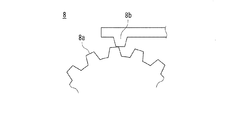
上記ギヤ機構4には、ギヤ軸4aに連結されたパーキングギヤ8aと、このパーキングギヤ8aと噛み合ってその回転を停止した状態でロックするパーキングロックポール(Pロックピン)8bとを備えたパーキングロック機構8が取り付けられている(図5を参照)。パーキングロックポール8bは、パーキングECU14より図示しないパーキングアクチュエータが駆動制御されることによって作動する。パーキングECU14は上記ハイブリッドECU10と通信を行い、このハイブリッドECU10からの指令信号を受けてパーキングアクチュエータを制御する。具体的には、シフト操作装置60(図2を参照)が駐車ポジション(Pポジション)以外のポジションから駐車ポジションへ操作された際(後述するPスイッチ62が押し込み操作された際;以下では、Pスイッチ62が押し込み操作された状態を「シフト操作装置60がPポジションにある」と表現することとする)には、パーキングECU14からのロック指令信号に従ってパーキングアクチュエータが駆動し、パーキングロックポール8bがパーキングギヤ8aに噛み合うことで、間接的に前輪6a,6bをロックする。一方、シフト操作装置60が駐車ポジションから他のポジションへ操作された際(Pスイッチ62が押し込まれた状態が解除された際)には、パーキングECU14からのロック解除指令信号に従ってパーキングアクチュエータが駆動し、パーキングロックポール8bがパーキングギヤ8aから離脱されることで前輪6a,6bのロックを解除する。
The gear mechanism 4 includes a
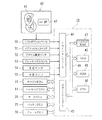
ここでシフト操作装置60について簡単に説明する。図2に示すように、このシフト操作装置60は、運転席の近傍に配置され、変位操作可能なシフトレバー(シフトノブと呼ぶ場合もある)61と、押し込み操作可能なPスイッチ62とが設けられている。シフトレバー61は、前進走行用のドライブレンジ(Dレンジ)、アクセルオフ時の制動力(エンジンブレーキ)が大きくなる前進走行用のブレーキレンジ(Bレンジ)、後進走行用のリバースレンジ(Rレンジ)、中立のニュートラルレンジ(Nレンジ)が設定されており、運転者が所望のレンジへシフトレバー61を変位させることが可能となっている。これらDレンジ、Bレンジ、Rレンジ、Nレンジの各位置はシフトポジションセンサ50によって検出される。シフトポジションセンサ50の出力信号はハイブリッドECU10に入力される。また、Pスイッチ62は、運転者の押し込み操作によって駐車ポジション(Pポジション)を設定するものであり、このPスイッチ62の押し込み信号もシフトポジションセンサ50によって検出される。そして、このPスイッチ62の押し込み操作に伴って、ハイブリッドECU10からの指令信号をパーキングECU14が受け、パーキングアクチュエータの駆動により、上記パーキングロック機構8が作動してパーキングロックポール8bがパーキングギヤ8aに噛み合う方向に移動することになる。
Here, the
モータジェネレータMG1,MG2は、何れも発電機として駆動できると共に電動機として駆動できる周知の同期発電電動機により構成されており、インバータ12,13及び昇圧コンバータ15を介してバッテリ16との間で電力のやりとりを行う。各インバータ12,13、昇圧コンバータ15及びバッテリ16を接続する電力ライン17は、各インバータ12,13が共用する正極母線及び負極母線として構成されており、モータジェネレータMG1,MG2の何れかで発電される電力を他のモータで消費することができるようになっている。したがって、バッテリ16は、モータジェネレータMG1,MG2の何れかから生じた電力や不足する電力により充放電されることになる。尚、モータジェネレータMG1,MG2により電力収支のバランスをとるものとすれば、バッテリ16は充放電されない。
Motor generators MG1 and MG2 are both configured as well-known synchronous generator motors that can be driven as generators and motors, and exchange power with
モータジェネレータMG1,MG2は、何れもモータ用電子制御ユニット(以下、モータECUという)20により駆動制御されている。モータECU20には、モータジェネレータMG1,MG2を駆動制御するために必要な信号、例えばモータジェネレータMG1,MG2のロータの回転位置を検出する回転位置検出センサ21,22からの信号や図示しない電流センサにより検出されるモータジェネレータMG1,MG2に印加される相電流などが入力されており、モータECU20からは、インバータ12,13へのスイッチング制御信号が出力されている。モータECU20は、ハイブリッドECU10と通信しており、このハイブリッドECU10からの制御信号によってモータジェネレータMG1,MG2を駆動制御すると共に必要に応じてモータジェネレータMG1,MG2の運転状態に関するデータをハイブリッドECU10に出力する。
Motor generators MG1 and MG2 are both driven and controlled by a motor electronic control unit (hereinafter referred to as motor ECU) 20. The
バッテリ16は、バッテリ用電子制御ユニット(以下、バッテリECUという)25によって管理されている。バッテリECU25には、バッテリ16を管理するのに必要な信号、例えば、バッテリ16の端子間に設置された図示しない電圧センサからの端子間電圧,バッテリ16の出力端子に接続された電力ライン17に取り付けられた図示しない電流センサからの充放電電流,バッテリ16に取り付けられた図示しない温度センサからの電池温度などが入力されており、必要に応じてバッテリ16の状態に関するデータを通信によりハイブリッドECU10に出力する。また、バッテリECU25では、バッテリ16を管理するために電流センサにより検出された充放電電流の積算値に基づいて残容量(SOC)を演算したり、演算した残容量(SOC)と電池温度Tbとに基づいてバッテリ16を充放電してもよい最大許容電力である入出力制限Win,Woutを演算している。なお、バッテリ16の入出力制限Win,Woutは、電池温度Tbに基づいて入出力制限Win,Woutの基本値を設定し、バッテリ16の残容量(SOC)に基づいて出力制限用補正係数と入力制限用補正係数とを設定し、設定した入出力制限Win,Woutの基本値に補正係数を乗じることにより設定することができる。
The
前輪6a,6bには、ブレーキアクチュエータ31からの油圧により作動する油圧ブレーキ34a,34bが取り付けられている。ブレーキアクチュエータ31からの油圧の調節は、ブレーキECU30による駆動制御により行われている。これらブレーキECU30、ブレーキアクチュエータ31、油圧ブレーキ34a,34bによって本発明でいうブレーキ装置が構成されている。
上記ブレーキECU30には、前後加速度センサ(Gセンサ)32及び車輪速度センサ33が接続されている。前後加速度センサ32は、車体前後方向の加速度を検出するものであり、車両の加減速度や路面勾配などの検出が可能である。また、車輪速度センサ33は、各車輪(駆動輪)6a,6bに設けられ、それぞれの車輪6a,6bの回転速度が検出可能である。また、ブレーキECU30からはブレーキアクチュエータ31へ駆動信号などが出力ポートを介して出力されている。尚、ブレーキECU30は、ハイブリッドECU10と通信しており、ハイブリッドECU10からの制御信号によりブレーキアクチュエータ31を駆動制御すると共に必要に応じてブレーキアクチュエータ31の状態や前輪6a,6bの状態に関するデータをハイブリッドECU10に出力する。
A longitudinal acceleration sensor (G sensor) 32 and a
上記ハイブリッドECU10は、図2に示すように、CPU40、ROM41、RAM42及びバックアップRAM43などを備えている。ROM41は、各種制御プログラムや、それら各種制御プログラムを実行する際に参照されるマップ等が記憶されている。CPU40は、ROM41に記憶された各種制御プログラムやマップに基づいて各種の演算処理を実行する。RAM42は、CPU40での演算結果や各センサから入力されたデータ等を一時的に記憶するメモリである。バックアップRAM43は、例えばイグニッションOFF時にその保存すべきデータ等を記憶する不揮発性のメモリである。
As shown in FIG. 2, the
以上のCPU40、ROM41、RAM42及びバックアップRAM43は、バス46を介して互いに接続されるとともに、入力インターフェース44及び出力インターフェース45と接続されている。
The
入力インターフェース44には、上記シフトポジションセンサ50、運転者のON操作によりイグニッション信号を発信するイグニッションスイッチ51、アクセルペダルの踏み込み量を検出するアクセル開度センサ52、ブレーキペダルの踏み込み量を検出するブレーキペダルセンサ53、車体速度(路面との相対速度)を検出する車速センサ54、エンジン2の冷却水温度を検出する水温センサ55等が接続されている。尚、水温センサ55が上記エンジンECU11に接続され、このエンジンECU11との通信によってハイブリッドECU10が冷却水温度情報を取得する構成としてもよい。
The
これにより、ハイブリッドECU10には、シフトポジションセンサ50からのシフトポジション信号、イグニッションスイッチ51からのイグニッション信号、アクセル開度センサ52からのアクセル開度信号、ブレーキペダルセンサ53からのブレーキペダルポジション信号、車速センサ54からの車速信号、水温センサ55からの水温信号等が入力されるようになっている。
Thus, the
また、入力インターフェース44及び出力インターフェース45には、上記エンジンECU11、パーキングECU14、モータECU20、バッテリECU25、ブレーキECU30が接続されており、ハイブリッドECU10は、これらエンジンECU11、パーキングECU14、モータECU20、バッテリECU25、ブレーキECU30との間で各種制御信号やデータのやりとりを行っている。
The
このように構成されたハイブリッド車両1は、運転者によるアクセルペダルの踏み込み量に対応するアクセル開度Accと車速Vとに基づいて車輪(駆動輪)6a,6bに出力すべきトルク(要求トルク)を計算し、この要求トルクに対応する要求動力により走行するように、エンジン2とモータジェネレータMG1,MG2とが運転制御される。具体的には、燃料消費量の削減を図るために、要求駆動力が比較的低い運転領域にあっては、第2モータジェネレータMG2を利用して上記要求駆動力が得られるようにする。一方、要求駆動力が比較的高い運転領域にあっては、第2モータジェネレータMG2を利用すると共に、エンジン2を駆動し、これら駆動源(走行用駆動力源)からの駆動力により、上記要求駆動力が得られるようにする。
In the
より具体的には、車両の発進時や低速走行時等であってエンジン2の運転効率が低い場合には、第2モータジェネレータMG2のみにより走行(以下、「EV走行」ともいう)を行う。また、車室内に配置された走行モード選択スイッチによって運転者がEV走行モードを選択した場合にもEV走行を行う。
More specifically, when the driving efficiency of the
一方、通常走行時には、例えば上記動力分割機構3によりエンジン2の駆動力を2経路に分け(トルクスプリット)、一方で駆動輪6a,6bの直接駆動(直達トルクによる駆動)を行い、他方で第1モータジェネレータMG1を駆動して発電を行う。この時、発生する電力で第2モータジェネレータMG2を駆動して駆動輪6a,6bの駆動補助を行う(電気パスによる駆動)。このように、上記動力分割機構3が差動機構として機能し、その差動作用によりエンジン2からの動力の主部を駆動輪6a,6bに機械的に伝達し、そのエンジン2からの動力の残部を第1モータジェネレータMG1から第2モータジェネレータMG2への電気パスを用いて電気的に伝達することにより、電気的に変速比が変更される電気式無段変速機としての機能が発揮される。これにより、駆動輪6a,6b(リングギヤ3b,7b)の回転数及びトルクに依存することなく、エンジン回転数及びエンジントルクを自由に操作することが可能となり、駆動輪6a,6bに要求される駆動力を得ながらも、燃料消費率が最適化されたエンジン2の運転状態を得ることが可能となる。
On the other hand, during normal travel, for example, the driving force of the
また、高速走行時には、さらにバッテリ(走行用バッテリ)16からの電力を第2モータジェネレータMG2に供給し、この第2モータジェネレータMG2の出力を増大させて駆動輪6a,6bに対して駆動力の追加(駆動力アシスト;力行)を行う。
Further, at the time of high speed traveling, the electric power from the battery (traveling battery) 16 is further supplied to the second motor generator MG2, and the output of the second motor generator MG2 is increased to drive the driving
更に、減速時には、第2モータジェネレータMG2が発電機として機能して回生発電を行い、回収した電力をバッテリ16に蓄える。尚、バッテリ16の充電量が低下し、充電が特に必要な場合には、エンジン2の出力を増加して第1モータジェネレータMG1による発電量を増やしてバッテリ16に対する充電量を増加する。もちろん、低速走行時においても必要に応じてエンジン2の駆動量を増加する制御を行う場合もある。例えば、前述のようにバッテリ16の充電が必要な場合や、エアコン等の補機を駆動する場合や、エンジン2の冷却水の温度を所定温度まで上げる場合や、車両が急加速する場合等である。
Furthermore, at the time of deceleration, the second motor generator MG2 functions as a generator to perform regenerative power generation, and the recovered power is stored in the
さらに、上記ハイブリッド車両においては、車両の運転状態やバッテリ16の状態によって、燃費を向上させるために、エンジン2を停止させる。そして、その後も、車両の運転状態やバッテリ16の状態を検知して、エンジン2を再始動させる。このように、ハイブリッド車両においては、イグニッションスイッチがON位置であってもエンジン2は間欠運転される。このため、シフト操作装置60の操作状態が駐車ポジション(Pポジション)にあり、パーキングロック機構8がロック状態(パーキングロックポール8bがパーキングギヤ8aに噛み合っている状態)において、車室内の暖房要求やバッテリ16の充電要求等が生じた場合にもエンジン2が始動されることになる。
Furthermore, in the hybrid vehicle, the
そして、このように車両が停止している状態でエンジン2が駆動している場合、上記動力分割機構3、リダクション機構7、ギヤ機構4等におけるギヤ同士の間に隙間(バックラッシ等)が存在していることに起因し、エンジン2のトルク変動の影響によって異音(歯打ち音)が生じる可能性がある。このため、このような状況では、互いに噛み合っているギヤの一方の歯を他方の歯に押し当てるための押し当てトルクが上記第2モータジェネレータMG2から発生されることになる(異音低減制御)。
When the
−押し当てトルク制御−
次に、本実施形態の特徴とする動作として、ハイブリッド車両1の停車中にシフト操作装置60がPポジションへ操作された場合に行われる押し当てトルク制御について具体的に説明する。
-Pushing torque control-
Next, as an operation characteristic of the present embodiment, a pressing torque control performed when the
先ず、この押し当てトルク制御の概略について説明する。この押し当てトルク制御では、シフト操作装置60がPポジションへ操作された状態でエンジン2が駆動している場合に、エンジン2の冷却水温度が所定温度よりも低い冷間時にあっては、そのエンジン2の運転状態が負荷運転状態と自立運転状態との間で切り換わったとしても(これらの運転状態については後述する)、上記押し当てトルクの作用方向を変化させないようにしている(本発明でいう、電動機から動力伝達系に与えられるトルクの作用方向を一方向に維持する制御)。つまり、従来技術にあっては、エンジン2の冷間時及び温間時に関わりなく、エンジン2の運転状態の変化(負荷運転状態と自立運転状態との間での切り換え)に応じて押し当てトルクの作用方向を変化させるようにしていたのに対し、本実施形態の押し当てトルク制御にあっては、冷間時にあっては、エンジン2の運転状態が切り換わったとしても、上記押し当てトルクの作用方向を変化させないようにしている。また、この際の押し当てトルクとしては、温間時における押し当てトルクよりも増大されている。以下では、この冷間時における押し当てトルク制御を「押し当てトルク増大制御」と呼ぶ。
First, an outline of the pressing torque control will be described. In this pressing torque control, when the
また、このような冷間時における押し当てトルク増大制御が行われている場合に、押し当てトルク増大禁止条件が成立した場合には、この押し当てトルク増大制御を解除し、通常の押し当てトルク制御に復帰させる。また、冷間時において押し当てトルク増大禁止条件が既に成立している場合には、この押し当てトルク増大制御の実行を禁止する。 In addition, when the pressing torque increase control is performed in the cold state and the pressing torque increase prohibition condition is satisfied, the pressing torque increase control is canceled and the normal pressing torque is increased. Return to control. Further, when the pressing torque increase prohibition condition is already established in the cold state, the execution of the pressing torque increase control is prohibited.
押し当てトルク増大禁止条件としては、シフト操作装置60がPポジションから非Pポジションへ操作されることや、路面勾配が所定の閾値よりも大きい場合が挙げられるが、前者の場合(シフト操作装置60がPポジションから非Pポジションへ操作される場合)には、シフト操作装置60の操作を上記シフトポジションセンサ50によってモニタしておき、シフト変更の確定前に押し当てトルクを減少させていく操作を行う。また、その際の押し当てトルクの減少割合(以下、「トルクレート」と呼ぶ場合もある)を大きく設定して上記パーキングギヤ8aの歯の側面がパーキングロックポール8bに強圧されている状態を早期に解消するようにしている。一方、路面勾配が所定の閾値よりも大きい場合には、押し当てトルクの増大を禁止し、仮にパーキングロックポール8bがパーキングギヤ8aに噛み合っていない状況(図5に示す状況)で、上記押し当てトルクを増大したことに伴う車両の移動(押し当てトルクが増大されたことに起因して車両が発進すること)を阻止する。
The pushing torque increase prohibition condition includes a case where the
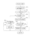
図3は、この押し当てトルク制御の手順を示すフローチャートである。このフローチャートは、シフト操作装置60の操作によりPスイッチ62が押し込み操作されたときに実行される。尚、この際、パーキングECU14がパーキングアクチュエータを駆動制御することによってパーキングロックポール8bがパーキングギヤ8aに噛み合うようパーキングロック機構8が駆動されるが、パーキングギヤ8aの回転位置によってパーキングロックポール8bとパーキングギヤ8aとが噛み合ったり噛み合わなかったりする。図5に、パーキングロックポール8bとパーキングギヤ8aとが噛み合っていない状態にあるパーキングロック機構8の様子の一例を示す。
FIG. 3 is a flowchart showing the procedure of the pressing torque control. This flowchart is executed when the
シフト操作装置60の操作(Pスイッチ62の押し込み操作)によりシフトポジションがPポジションに変更されると、ハイブリッドECU10は、ステップST1において、ハイブリッドシステムの運転状態量を読み込む。例えば、ハイブリッドシステムのReadyON状態、アクセル開度、車速、モータジェネレータMG1,MG2の回転数Nm1,Nm2、エンジン2の冷却水温度Thwなどのデータを入力する処理を実行する。
When the shift position is changed to the P position by the operation of the shift operation device 60 (the pressing operation of the P switch 62), the
こうしてハイブリッドシステムの運転状態量が入力されると、ステップST2に移り、エンジン2の始動要求が生じたか否かを判定する。例えば、排気系に備えられた触媒の活性化要求、乗員の空調要求、バッテリ16の充電要求(バッテリ16の残容量(SOC)の低下に伴う充電要求)等によってエンジン2の始動要求が生じたか否かを判定する。
When the operating state quantity of the hybrid system is input in this way, the process proceeds to step ST2, and it is determined whether or not a start request for the
エンジン2の始動要求が生じておらず、エンジン2が継続して停止する場合には、ステップST2でNO判定されてリターンされる。
If the
一方、エンジン2の始動要求が生じ、ステップST2でYES判定された場合には、ステップST3に移り、エンジン2の冷却水温度が所定値α未満であるか否かを判定する。つまり、エンジン2の冷間時であるか否かを判定する。上記所定値αとしては例えば70℃に設定される。この値はこれに限定されるものではない。
On the other hand, when a request for starting the
エンジン2の冷却水温度が所定値α以上であり、ステップST3でNO判定された場合、つまり、エンジン2の温間時である場合には、ステップST4に移り、エンジン2の運転状態が切り換わったか否かを判定する。具体的には、エンジン2の運転状態が負荷運転状態と自立運転状態との間で切り換わったか否かを判定する。この判定は、予め設定されている自立運転要求フラグF1及び負荷運転要求フラグF2を認識することにより行われる。
If the coolant temperature of the
自立運転要求フラグF1は、本実施形態では、図示しないエンジン運転要求フラグ設定ルーチンにより、エンジン2の排気系に設けられた触媒の温度がその活性温度範囲の下限温度未満であるために触媒の暖機が必要なときや、図示しない空調装置によって車室内を暖房するためにエンジン2を熱源として用いる必要があるときなどエンジン2の自立運転(無負荷運転)が要求されているときには値「1」が設定され、それ以外のときには値「0」が設定される。
In the present embodiment, the self-sustained operation request flag F1 is determined by the engine operation request flag setting routine (not shown) because the temperature of the catalyst provided in the exhaust system of the
エンジン2の負荷運転要求フラグF2は、本実施形態では、同じくエンジン運転要求フラグ設定ルーチンにより、バッテリ16の残容量(SOC)がその管理目標範囲の下限値Slow(例えば、30%や40%など)未満に至りバッテリ16を充電するためにエンジン2の負荷運転が要求されているときには値「1」が設定され、バッテリ16を充電するためのエンジン2の負荷運転が要求されていないときや、こうした要求がなされた以降にバッテリ16の残容量(SOC)がその充電によって下限値Slowより若干大きい値以上に至ったときには値「0」が設定される。なお、負荷運転要求フラグF2に値「1」が設定されたときには自立運転要求フラグF1に値「0」が設定される。
In the present embodiment, the load operation request flag F2 of the
このステップST4においてエンジン2の運転状態が切り換わっていない、つまり、負荷運転状態または自立運転状態が継続されていると判定された場合にはNO判定されてリターンされる。
If it is determined in step ST4 that the operation state of the
一方、エンジン2の運転状態が負荷運転状態と自立運転状態との間で切り換わり、ステップST4でYES判定された場合には、ステップST5に移り、押し当てトルクの作用方向の切り換えを行う。例えば、負荷運転状態において、第2モータジェネレータMG2からの押し当てトルクを車両が後退する側の回転方向に作用させていた場合に、自立運転状態に切り換わった際には、第2モータジェネレータMG2からの押し当てトルクを車両が前進する側の回転方向に切り換えることになる。これにより、上記特許文献3に開示されている如く、歯打ち音を抑制すると共に、パーキングロック機構8におけるパーキングギヤ8aに対するパーキングロックポール8bの噛み合わせを適正に行う。この運転状態と押し当てトルクの作用方向との関係は上述したものには限定されない。つまり、エンジン2が負荷運転状態にある際には、第2モータジェネレータMG2からの押し当てトルクを車両が前進する側の回転方向に作用させ、エンジン2が自立運転状態にある際には、第2モータジェネレータMG2からの押し当てトルクを車両が後退する側の回転方向に作用させるようにしてもよい。
On the other hand, when the operation state of the
一方、エンジン2の冷却水温度が所定値α未満であり、ステップST3でYES判定された場合には、ステップST6に移り、第2モータジェネレータMG2からの押し当てトルク増大制御を実行する。
On the other hand, if the coolant temperature of
この押し当てトルク増大制御として具体的には、この第2モータジェネレータMG2からの押し当てトルクの作用方向を車両が前進する側の回転方向とし、且つそのトルクを増大させるものである。また、この増大される押し当てトルクとしては、上述したエンジン2の温間時における押し当てトルクよりも大きく、上記歯打ち音の発生が確実に阻止できる値に設定される。このため、例えば、エンジン2の負荷運転状態にあっては、必要最小限の押し当てトルク(歯打ち音の発生が阻止できる最小必要押し当てトルク)は変動するため、それに応じて、上記増大される押し当てトルクも変更されることになる。ここで設定される押し当てトルクは、予め実験やシミュレーションによって作成された押し当てトルクマップに従って設定される。この押し当てトルクマップは、エンジン2の運転状態などに応じ、上記歯打ち音の発生が阻止できる最小必要押し当てトルクよりも僅かに大きい押し当てトルクを設定するものとなっている。また、本実施形態では、この押し当てトルクマップで設定される押し当てトルクは、常に車両が前進する側の回転方向に作用するものとして求められる。尚、この際に設定される押し当てトルクの作用方向は車両が後退する側の回転方向であってもよく、この場合、押し当てトルクマップで設定される押し当てトルクは、常に車両が後退する側の回転方向に作用するものとして求められることになる。
More specifically, the pressing torque increase control is such that the direction of operation of the pressing torque from the second motor generator MG2 is the rotational direction on the vehicle forward side, and the torque is increased. Further, the increased pressing torque is set to a value that is larger than the pressing torque when the
このようにして押し当てトルク増大制御が実行されている状態で、ステップST7に移り、押し当てトルク増大禁止条件が成立したか否かが判定される。この押し当てトルク増大禁止条件の例としては、上述した如く、シフト操作装置60がPポジションから非Pポジションへ操作されることや、路面勾配が所定の閾値よりも大きい場合が挙げられる。上記シフト操作装置60がPポジションから非Pポジションへ操作されたことは、上記シフトポジションセンサ50からの出力信号によって現在のシフトポジション(実際には、Pスイッチ62の押し込み状態が解除されたか否か)によって判定される。また、路面勾配は、上記前後加速度センサ32の出力信号に基づいて求められる。また、その他の押し当てトルク増大禁止条件としては、エンジン2の暖機完了、エンジン2の停止、図示しない油圧センサの異常等も挙げられる。
With the pressing torque increase control being executed in this way, the process proceeds to step ST7, where it is determined whether or not the pressing torque increase prohibition condition is satisfied. As an example of the pressing torque increase prohibition condition, as described above, the
押し当てトルク増大禁止条件が成立しておらず、ステップST7でNO判定された場合には、この押し当てトルク増大禁止条件が成立するまで押し当てトルク増大制御を継続する。 If the pressing torque increase prohibition condition is not satisfied and a negative determination is made in step ST7, the pressing torque increase control is continued until the pressing torque increase prohibition condition is satisfied.
一方、押し当てトルク増大禁止条件が成立し、ステップST7でYES判定された場合には、ステップST8に移り、押し当てトルク増大制御を解除して通常の押し当てトルク制御に戻る。例えば、エンジン2の暖機が完了したことで押し当てトルク増大禁止条件が成立した場合には、押し当てトルクが減少される。また、エンジン2の停止によって押し当てトルク増大禁止条件が成立した場合には、例えば押し当てトルクが「0」に設定される。
On the other hand, if the pressing torque increase prohibition condition is satisfied and YES is determined in step ST7, the process proceeds to step ST8, the pressing torque increasing control is canceled, and the normal pressing torque control is resumed. For example, when the pressing torque increase prohibition condition is satisfied because the warm-up of the
以上の動作が繰り返されることにより、エンジン2の温間時にはエンジン2の運転状態の切り換わりに伴って押し当てトルクの作用方向を切り換えるのに対し(上記ステップST4及びステップST5の動作)、エンジン2の冷間時にはエンジン2の運転状態が切り換わっても押し当てトルクの作用方向を切り換えることなく、上述した押し当てトルク増大制御が実行されることになる(上記ステップST6及びステップST7の動作)。これにより、エンジン2の冷間時にあっては、押し当てトルクの作用方向が切り換わって一時的に押し当てトルクが「0」になるといった状況は生じず、常に高い押し当てトルクが確保されることになって歯打ち音抑制効果が継続的に発揮されることになる。つまり、特にエンジン2のトルク変動が大きいために歯打ち音が発生する可能性が高い冷間時において、押し当てトルクの作用方向を切り換えないようにすることで、常に高い押し当てトルクを確保し、これによって異音抑制効果を継続的に得ることができる。
By repeating the above operation, the operation direction of the pressing torque is switched in accordance with the switching of the operation state of the
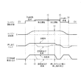
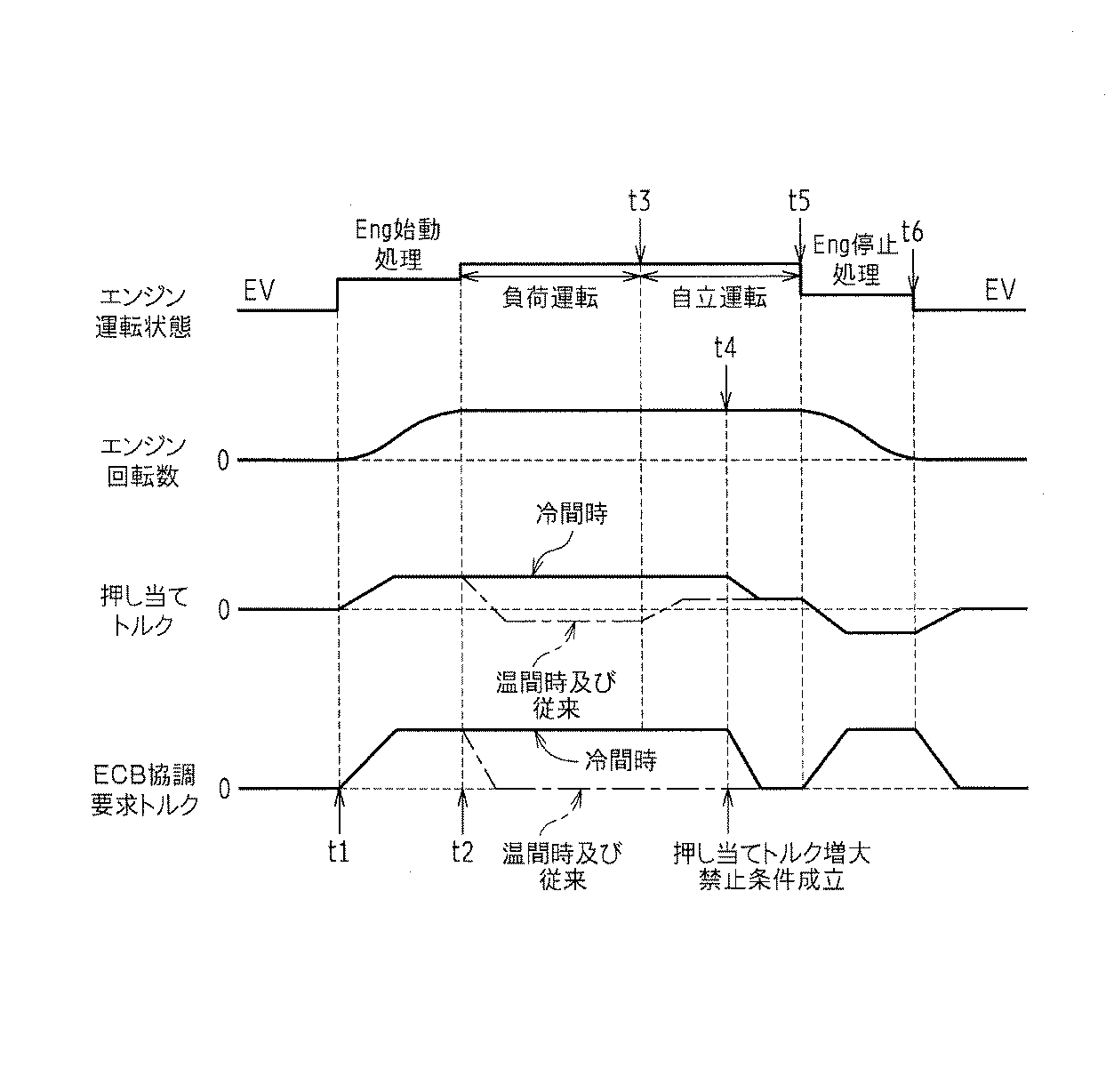
図4は、上述した押し当てトルク増大制御が実行された場合におけるエンジン2の運転状態、エンジン回転数、押し当てトルク、ECB(Electronic Control Brake)協調要求トルクの変化を示す図である。この図4では、本実施形態に係る押し当てトルク増大制御実行時における押し当てトルクの変化及びECB協調要求トルクの変化を実線で、従来の押し当てトルクの変化及びECB協調要求トルクの変化を一点鎖線でそれぞれ示している。
FIG. 4 is a diagram illustrating changes in the operating state of the
また、ここでは、バッテリ16の残容量(SOC)がその管理目標範囲の下限値Slow未満に至りバッテリ16を充電する必要が生じたことでエンジン2の始動要求がなされた場合を例に挙げて説明する。つまり、エンジン2の始動初期時には負荷運転が行われる場合を例に挙げて説明する。また、エンジン2の停止要求がなされたことで押し当てトルク増大禁止条件が成立した場合を例に挙げて説明する。
In addition, here, a case where the
尚、ECB協調要求トルクとは、上記ブレーキECU30によるブレーキアクチュエータ31の制御により、各前輪6a,6bに備えられた油圧ブレーキ34a,34bによる制動力に相当するトルクであって、上記押し当てトルクによって車両が発進することがないようにするための制動力を得るトルクである。つまり、仮にパーキングロックポール8bがパーキングギヤ8aに噛み合っていない状況(図5に示すような状況)で、押し当てトルクを増大したことに伴って車両が発進することがないようにするためのトルクである。
The ECB coordination required torque is a torque corresponding to the braking force by the
先ず、エンジン2の停止状態において始動要求が生じると(タイミングt1)、エンジン2の始動処理が行われた後、エンジン2の負荷運転が開始される(タイミングt2)。このエンジン2の始動処理期間中には、第1モータジェネレータMG1によるエンジン2のクランキングが行われ、エンジン回転数が所定回転数に達した時点でインジェクタからの燃料噴射及び点火プラグの点火が行われることでエンジン2が始動に至る。また、このエンジン2の始動処理中には、上記押し当てトルク及びECB協調要求トルクが共に増大するように制御される。そして、エンジン2の負荷運転が開始された時点(タイミングt2)では、押し当てトルク及びECB協調要求トルクは共に既に高い値に設定されており、歯打ち音の発生は防止され、且つ押し当てトルクを増大したことに起因する車両の発進も防止されている。
First, when a start request is generated when the
エンジン2の負荷運転が開始された後、バッテリ16の残容量(SOC)が所定量に達したことで負荷運転要求が解除され、自立運転要求が生じた場合(タイミングt3)、この押し当てトルク増大制御では、押し当てトルクの作用方向は切り換えられず、且つその押し当てトルクの大きさも高く維持される。上述した如く、押し当てトルクは、歯打ち音の発生が阻止できる最小必要押し当てトルクよりも所定量だけ高い値に調整されるため、エンジン2の運転状態に応じて変更される可能性があるが、図4で示すものは、この押し当てトルクが一定に維持された状態を示している。尚、本実施形態では、上記押し当てトルク増大制御の実行中の所定期間にあっては、仮に押し当てトルクが変動したとしても、ECB協調要求トルクは高い値で且つ一定の値に維持されるようにしている。これは、上記ブレーキアクチュエータ31に備えられている油圧制御バルブの耐久性を維持するためである。
After the load operation of the
その後、エンジン2の停止要求がなされ、押し当てトルクの増大禁止条件が成立すると(タイミングt4)、エンジン2の運転状態としては自立運転状態が継続されたまま押し当てトルク及びECB協調要求トルクが共に低下され、これら押し当てトルク及びECB協調要求トルクが所定値にまで低下した後の所定時間経過後(タイミングt5)にエンジン2の運転状態がエンジン停止処理に移行し、その後、エンジン2は停止される(タイミングt6)。
After that, when the
尚、このエンジン停止処理中において、押し当てトルクは、上記押し当てトルク増大制御の実行中のトルク作用方向とは逆方向(例えば、車両が後退する側の回転方向)の押し当てトルクが付与される。また、それに同期してECB協調要求トルクが一時的に増大され、押し当てトルクが付与されたことに伴って車両が発進(後退)してしまうことを阻止している。 Note that during this engine stop process, the pressing torque is applied in the direction opposite to the direction of torque application during the execution of the pressing torque increase control (for example, the rotational direction on the side where the vehicle moves backward). The In addition, the ECB cooperation required torque is temporarily increased in synchronization therewith, and the vehicle is prevented from starting (retreating) in accordance with the application of the pressing torque.
−路面勾配による押し当てトルクの増大禁止条件−
次に、上述した押し当てトルク増大禁止条件の一つである路面勾配の判定手法について説明する。これは、図5に示すように、仮にパーキングロックポール8bがパーキングギヤ8aに噛み合っていない状況において、降坂路で、車両が前進する側の回転方向への押し当てトルクを増大させたことによってパーキングロックポール8bがパーキングギヤ8aに噛み合うことができなくなるといった状況を回避するための判定動作である。つまり、パーキングギヤ8aが回転して、パーキングロックポール8bがパーキングギヤ8aの溝に対向する位置に達した時点でのパーキングギヤ8aの回転速度が所定速度以上になっている場合には、パーキングロックポール8bがパーキングギヤ8aの溝に嵌り込むことができなくなる可能性がある。そして、上記押し当てトルク増大制御を実行したことでこのような状況が発生すると推測される場合には押し当てトルク増大制御を禁止し、パーキングロックポール8bがパーキングギヤ8aの溝に嵌り込むことを可能にするために路面勾配を判定するようにしている。以下、図6を参照しながら具体的に説明する。
-Conditions for prohibiting increase in pushing torque due to road surface gradient-
Next, a road surface gradient determination method, which is one of the above-described pressing torque increase prohibition conditions, will be described. As shown in FIG. 5, in the situation where the
先ず、仮にブレーキシステム(上記油圧ブレーキ34a,34b等)がフェールした場合の車両加速度は以下の式(1)で与えられる。
First, the vehicle acceleration when the brake system (the
ここで、aは車両加速度、Fは車両の前後方向に作用する力、mは基準車体重量、gは重力の加速度、θは推定路面勾配、Tpkbはリングギヤ軸3eに作用する押し当てトルク、DEFはデファレンシャルギヤ5のギヤ比、SWRはタイヤ半径である。
Here, a is the vehicle acceleration, F is the force acting in the longitudinal direction of the vehicle, m is the reference body weight, g is the acceleration of gravity, θ is the estimated road surface gradient, Tpkb is the pressing torque acting on the ring gear shaft 3e, DEF Is the gear ratio of the
そして、パーキングロックポール8bとパーキングギヤ8aの溝位置とが対向する位置までパーキングギヤ8aが回転した際の車速Vは以下の式(2)から求められる。
And the vehicle speed V when the
ここで、Vは車速、Lはパーキングロックポール8bがパーキングギヤ8aに噛み合うまでの車両推定移動距離である。
Here, V is the vehicle speed, and L is the estimated vehicle travel distance until the
更に、パーキングロックポール8bとパーキングギヤ8aの溝位置とが対向する位置までパーキングギヤ8aが回転した場合であっても、このパーキングギヤ8aの回転速度が高いために両者が噛み合うことのできない速度Vmax(噛み合うことのできなくなる車速Vの下限値)を求め、これから、この速度Vmaxとなる路面勾配θを以下の式(3)〜(5)から求める。
Further, even when the
以上の式から、パーキングギヤ8aの溝位置を管理すれば、パーキングロックポール8bがパーキングギヤ8aの溝位置に達するまでの車両推定移動距離Lが以下の式(6)(7)から求められる。
From the above formula, if the groove position of the
ここで、θplck pはパーキングロックポール8bとパーキングギヤ8aの溝位置とのズレ角(リングギヤ軸3eの回転位相に換算した角度)、θpはパーキングギヤ8aの溝位置を基準としたリングギヤ軸3eの回転角、Nplckはパーキングギヤ8aの溝数である。
Here, θplck p is a deviation angle between the
以上の演算式より、上記車両推定移動距離と、増大後の押し当てトルクとから、上記押し当てトルクの増大禁止条件成立の閾値となる路面勾配の値が求まることになる。つまり、このようにして求められた路面勾配を超える勾配である場合にはトルク増大禁止条件が成立することになり、押し当てトルク増大制御が禁止されることになる。 From the above calculation formula, the value of the road surface gradient serving as a threshold value for establishing the condition for prohibiting the increase of the pressing torque is obtained from the estimated vehicle moving distance and the increased pressing torque. In other words, when the slope exceeds the road slope obtained in this way, the torque increase prohibition condition is satisfied, and the pressing torque increase control is prohibited.
−シフト操作による押し当てトルクの調整動作−
次に、シフト操作装置60がPポジションから非Pポジションへ操作されたことでトルクの増大禁止条件が成立した場合の具体的な動作について説明する。
-Adjusting operation of pushing torque by shift operation-
Next, a specific operation when the torque increase prohibition condition is satisfied by operating the
図7は、シフト操作装置60がPポジションから非Pポジションへ操作されたことでトルク増大禁止条件が成立した場合における、エンジン2の運転状態、実シフトの状態、シフトノブ位置、シフト要求、パーキングロックポール(Pロックピン)位置カウンタ、シフト確定情報、中断フラグ、中断時レートフラグ、押し当てトルクの変化を示す図である。この図7では、本実施形態における中断フラグ及び押し当てトルクの変化を実線で、従来の中断フラグ及び押し当てトルクの変化を一点鎖線でそれぞれ示している。
FIG. 7 shows the operating state of the
尚、上記エンジン2の運転状態、実シフトの状態、シフトノブ位置、シフト要求、シフト確定情報、中断フラグ、中断時レートフラグの各情報は上記ハイブリッドECU10に一体化された図示しないPM(Power Management)−ECU;電源制御用コンピュータ)によって取得される。また、上記Pロックピン位置カウンタは上記パーキングECU14に備えられている。
The operating state of the
先ず、所定の押し当てトルクを作用させている状態で、エンジン2の停止状態(EV)から始動要求が生じ、上記クランキング(CRK)を得て、エンジン2が始動される(DRV)。
First, in a state where a predetermined pressing torque is applied, a start request is generated from a stop state (EV) of the
その後、運転者によるシフトノブ(シフトレバー)61の操作が行われ、P(パーキング)位置からN(ニュートラル)位置を経てD(ドライブ)位置に達すると(タイミングt10)、その直後(図中の時間T1経過後におけるタイミングt11)においてシフト要求としてはP(パーキング)からNP(notパーキング)に切り換わる。この時点では、ハイブリッドシステムの実シフトの状態としては未だP(パーキング)状態にある。このタイミングと略同時に、中断フラグ及び中断時レートフラグが共にONされ、押し当てトルクが高いレートで低下していく(単位時間当たりの減少量が多く設定されて押し当てトルクが低下していく)。この際、押し当てトルクとしては所定の目標値STPPKB3に設定され、押し当てトルクが、この目標値STPPKB3に達するまで、上記中断時レートフラグがONに維持されることで押し当てトルクが高いレートで低下していく。尚、この目標値STPPKB3としては任意の値が設定可能であるが、本実施形態では、押し当てトルク増大制御が実行されなかったと仮定した場合の押し当てトルク(例えば温間時に設定される押し当てトルク)に設定されている。 Thereafter, the driver operates the shift knob (shift lever) 61, and when it reaches the D (drive) position from the P (parking) position through the N (neutral) position (timing t10), immediately thereafter (time in the figure). At timing t11) after the elapse of T1, the shift request is switched from P (parking) to NP (not parking). At this point, the actual shift state of the hybrid system is still in the P (parking) state. At substantially the same time as this, both the interruption flag and the interruption rate flag are turned ON, and the pushing torque decreases at a high rate (the amount of reduction per unit time is set to a large value and the pushing torque decreases). . At this time, the pushing torque is set to a predetermined target value STPPKB3, and the pushing rate flag is maintained ON until the pushing torque reaches the target value STPPKB3, so that the pushing torque is at a high rate. It goes down. Although an arbitrary value can be set as the target value STPPKB3, in this embodiment, a pressing torque (for example, a pressing set in the warm state) when it is assumed that the pressing torque increase control is not executed. Torque) is set.
このようにして高いレートで押し当てトルクが低下していき、上記中断フラグ及び中断時レートフラグが共にONされてからの時間T2経過後のタイミングt13で、押し当てトルクが目標値STPPKB3に達する。尚、Pロックピン位置カウンタは、上記中断フラグ及び中断時レートフラグが共にONされてからの時間T3経過後のタイミングt12からカウントを開始している。つまり、このタイミングt12からパーキングロックポール8bの離脱が開始されている。このため、パーキングロックポール8bの離脱開始時には既に押し当てトルクは小さくなっており、パーキングロックポール8bとパーキングギヤ8aの歯の側面との強圧状態は早期に解消されており、このパーキングロックポール8bの解除途中での拗り音(パーキングロックポール8bとパーキングギヤ8aとの摩擦音)の発生は回避される。
In this way, the pushing torque decreases at a high rate, and the pushing torque reaches the target value STPPKB3 at timing t13 after the elapse of time T2 after both the interruption flag and the interruption time flag are turned on. The P-lock pin position counter starts counting from timing t12 after the elapse of time T3 from when both the interruption flag and interruption rate flag are turned on. That is, the
そして、押し当てトルクが目標値STPPKB3に達すると、中断時レートフラグがOFFされ、単位時間当たりの減少量が少なく設定されて押し当てトルクが更に低下していくことになる。 When the pressing torque reaches the target value STPPKB3, the interruption rate flag is turned OFF, the amount of decrease per unit time is set to be small, and the pressing torque further decreases.
そして、パーキングロックポール8bの解除が完了(図中のタイミングt14)した後に、シフト状態がD(ドライブ)となり(タイミングt15)、それに伴ってシフト確定情報もD(ドライブ;NP)となって車両の発進が可能となる。
After the release of the
尚、図7では、タイミングt15以降においてシフトの部位置がDから変位されているが、D状態は維持されている。 In FIG. 7, the shift position is displaced from D after timing t15, but the D state is maintained.
−他の実施形態−
以上説明した実施形態では、FF(フロントエンジン・フロントドライブ)方式のハイブリッド車両の制御に本発明を適用した例を示したが、本発明はこれに限られることなく、FR(フロントエンジン・リアドライブ)方式のハイブリッド車両や、4輪駆動方式のハイブリッド車両の制御にも適用できる。
-Other embodiments-
In the embodiment described above, the example in which the present invention is applied to the control of the FF (front engine / front drive) type hybrid vehicle has been described. However, the present invention is not limited to this, and the FR (front engine / rear drive) is not limited thereto. ) Type hybrid vehicle and four-wheel drive type hybrid vehicle.
また、上記実施形態では、第1モータジェネレータMG1及び第2モータジェネレータMG2の2つの電動機が搭載されたハイブリッド車両の制御に本発明を適用した例を示したが、3つ以上の電動機が搭載されたハイブリッド車両の制御にも適用可能である。 In the above embodiment, the example in which the present invention is applied to the control of the hybrid vehicle on which the two motors of the first motor generator MG1 and the second motor generator MG2 are mounted is shown, but three or more motors are mounted. It can also be applied to control of hybrid vehicles.
また、上記実施形態では、冷間時においてエンジン2の運転状態が負荷運転から自立運転に切り換わった場合に押し当てトルクの作用方向を変化させない場合について説明した。本発明では、冷間時においてエンジン2の運転状態が自立運転から負荷運転に切り換わった場合にも押し当てトルクの作用方向は変化させないようにしている。
Further, in the above-described embodiment, a case has been described in which the operation direction of the pressing torque is not changed when the operation state of the
本発明は、内燃機関と電動機とが搭載されたハイブリッド車両において、動力伝達系で発生する異音を低減または防止するための押し当てトルクの制御に適用可能である。 INDUSTRIAL APPLICABILITY The present invention is applicable to control of pressing torque for reducing or preventing abnormal noise generated in a power transmission system in a hybrid vehicle equipped with an internal combustion engine and an electric motor.
1 ハイブリッド車両
2 エンジン(内燃機関)
2a クランクシャフト(内燃機関の出力軸)
3 動力分割機構
3a サンギヤ
3b リングギヤ
3d キャリア
8 パーキングロック機構
8a パーキングギヤ
8b パーキングロックポール
10 ハイブリッドECU
14 パーキングECU
20 モータECU
30 ブレーキECU
31 ブレーキアクチュエータ
34a,34b 油圧ブレーキ
55 水温センサ
6a,6b 前輪(駆動輪)
60 シフト操作装置
61 シフトレバー
62 Pスイッチ
MG1 第1モータジェネレータ(第1の電動機)
MG2 第2モータジェネレータ(第2の電動機)
1
2a Crankshaft (output shaft of internal combustion engine)
3 Power split mechanism
14 Parking ECU
20 Motor ECU
30 Brake ECU
31
60
MG2 Second motor generator (second electric motor)
Claims (9)
上記内燃機関の温間時には、この内燃機関の運転状態が負荷運転状態と自立運転状態との間で切り換わったことに伴い、上記異音低減制御において上記電動機から上記動力伝達系に与えられる上記トルクの作用方向を切り換える一方、上記内燃機関の冷間時には、この内燃機関の運転状態が上記負荷運転状態と上記自立運転状態との間で切り換わっても上記異音低減制御において上記電動機から上記動力伝達系に与えられる上記トルクの作用方向を一方向に維持する構成とされていることを特徴とするハイブリッド車両の制御装置。 When the internal combustion engine and the electric motor are provided as driving power sources for traveling, the operation state of the shift operating device is in the parking position, and the internal combustion engine is driven while the vehicle is stopped , the torque from the electric motor is obtained. In a control apparatus for a hybrid vehicle that performs abnormal noise reduction control that reduces or prevents the occurrence of abnormal noise in the power transmission system by giving to the power transmission system,
During the warm of the internal combustion engine, said the operating state of the internal combustion engine due to the switched between self-sustaining operation condition and the load operating state, given the power transmission system from the electric motor in the abnormal sound reduction control while switching the direction of action of torque, during the cold state of the internal combustion engine, the operating state of the internal combustion engine from the electric motor in the abnormal sound reduction control be switched between the load operation state and the self-sustaining operation condition control apparatus for a hybrid vehicle, characterized by being configured to maintain the acting direction of the torque applied to the drive train in one direction.
上記異音低減制御において、上記内燃機関の冷間時における上記電動機から上記動力伝達系に与えられる上記トルクは、上記内燃機関の温間時における上記電動機から上記動力伝達系に与えられる上記トルクよりも大きく設定されていることを特徴とするハイブリッド車両の制御装置。 In the hybrid vehicle control device according to claim 1,
In the abnormal sound reduction control, the torque applied to the power transmission system from the electric motor during the cold of the internal combustion engine, than the torque applied from the electric motor during the warm of the internal combustion engine to the power transmission system A control device for a hybrid vehicle, characterized in that the value is also set to be large.
上記電動機から上記動力伝達系に与えられる上記トルクの作用方向を一方向に維持する制御は、所定の条件が成立した場合に解除または禁止される構成となっていることを特徴とするハイブリッド車両の制御装置。Control of maintaining the direction of operation of the torque applied from the electric motor to the power transmission system in one direction is configured to be canceled or prohibited when a predetermined condition is satisfied. Control device.
上記電動機から上記動力伝達系に与えられる上記トルクの作用方向を一方向に維持する制御の解除条件は、上記シフト操作装置がパーキング状態から非パーキング状態に操作された場合に成立することを特徴とするハイブリッド車両の制御装置。The release condition of the control for maintaining the direction of operation of the torque applied from the electric motor to the power transmission system in one direction is satisfied when the shift operation device is operated from a parking state to a non-parking state. A control device for a hybrid vehicle.
上記シフト操作装置が上記パーキング状態から上記非パーキング状態に操作された場合、上記電動機から上記動力伝達系に与えられる上記トルクが所定値に低下するまでは、単位時間当たりのトルク減少量を大きく設定する一方、上記トルクが上記所定値に低下した後、単位時間当たりのトルク減少量を小さく設定することを特徴とするハイブリッド車両の制御装置。When the shift operating device is operated from the parking state to the non-parking state, a large torque reduction amount per unit time is set until the torque applied from the electric motor to the power transmission system decreases to a predetermined value. On the other hand, after the torque has decreased to the predetermined value, the torque reduction amount per unit time is set to be small.
上記電動機から上記動力伝達系に与えられる上記トルクの作用方向を一方向に維持する制御の禁止条件は、上記車両が停車している路面の勾配が所定勾配を超えている場合に成立することを特徴とするハイブリッド車両の制御装置。The prohibition condition of the control for maintaining the direction of operation of the torque applied from the electric motor to the power transmission system in one direction is established when the slope of the road surface on which the vehicle is stopped exceeds a predetermined slope. A hybrid vehicle control device.
パーキングギヤに対してパーキングロックポールを噛み合わせることにより駆動輪を停止させるパーキングロック機構を備えており、It has a parking lock mechanism that stops the drive wheel by engaging the parking lock pole with the parking gear.
上記電動機から上記動力伝達系に与えられる上記トルクの作用方向を一方向に維持する制御の禁止条件は、上記パーキングギヤに対して上記パーキングロックポールが噛み合っていない状態から噛み合い可能な位置まで上記パーキングギヤが回転した際における上記パーキングギヤの回転速度が上記パーキングロックポールの噛み合いが不能な所定速度以上になる車速となる路面勾配を超えている場合に成立することを特徴とするハイブリッド車両の制御装置。The prohibition condition of the control for maintaining the direction of operation of the torque applied from the electric motor to the power transmission system in one direction is that the parking lock pole is not meshed with the parking gear from the meshed position to the meshable position. The control apparatus for a hybrid vehicle, which is established when the rotation speed of the parking gear when the gear rotates exceeds a road surface gradient that becomes a vehicle speed at which the parking lock pole is engaged at a predetermined speed or higher. .
上記走行用駆動力源からの駆動力を受ける駆動輪には、この駆動輪の回転を阻止する制動力を発生するブレーキ装置が設けられており、The driving wheel that receives the driving force from the driving power source for traveling is provided with a brake device that generates a braking force that prevents rotation of the driving wheel.
上記電動機から上記動力伝達系に与えられる上記トルクの作用方向を一方向に維持する制御の実行時において、上記電動機から上記動力伝達系に与えられる上記トルクの大きさが変化しても、上記ブレーキ装置による上記駆動輪への制動力は一定に維持される構成となっていることを特徴とするハイブリッド車両の制御装置。Even when the magnitude of the torque applied from the electric motor to the power transmission system changes during execution of control for maintaining the direction of operation of the torque applied from the electric motor to the power transmission system in one direction, the brake A control apparatus for a hybrid vehicle, wherein the braking force applied to the drive wheels by the apparatus is maintained constant.
上記内燃機関の出力軸が連結されるプラネタリキャリアと、第1の電動機が連結されるサンギヤと、第2の電動機が連結されるリングギヤとを備えた遊星歯車機構により構成される動力分割機構を備えており、上記異音低減制御では、上記第2の電動機からのトルクにより上記動力伝達系での異音の発生を低減または防止する構成となっていることを特徴とするハイブリッド車両の制御装置。A power split mechanism including a planetary carrier to which the output shaft of the internal combustion engine is connected; a sun gear to which the first electric motor is connected; and a ring gear to which the second electric motor is connected. In the abnormal noise reduction control, the hybrid vehicle control device is configured to reduce or prevent the occurrence of abnormal noise in the power transmission system by the torque from the second electric motor.
Priority Applications (1)
| Application Number | Priority Date | Filing Date | Title |
|---|---|---|---|
| JP2011236198A JP5716634B2 (en) | 2011-10-27 | 2011-10-27 | Control device for hybrid vehicle |
Applications Claiming Priority (1)
| Application Number | Priority Date | Filing Date | Title |
|---|---|---|---|
| JP2011236198A JP5716634B2 (en) | 2011-10-27 | 2011-10-27 | Control device for hybrid vehicle |
Publications (2)
| Publication Number | Publication Date |
|---|---|
| JP2013091471A JP2013091471A (en) | 2013-05-16 |
| JP5716634B2 true JP5716634B2 (en) | 2015-05-13 |
Family
ID=48614937
Family Applications (1)
| Application Number | Title | Priority Date | Filing Date |
|---|---|---|---|
| JP2011236198A Active JP5716634B2 (en) | 2011-10-27 | 2011-10-27 | Control device for hybrid vehicle |
Country Status (1)
| Country | Link |
|---|---|
| JP (1) | JP5716634B2 (en) |
Families Citing this family (5)
| Publication number | Priority date | Publication date | Assignee | Title |
|---|---|---|---|---|
| JP6146373B2 (en) * | 2014-06-06 | 2017-06-14 | トヨタ自動車株式会社 | Control device for drive device for hybrid vehicle |
| EP3326056B1 (en) | 2015-07-17 | 2022-10-12 | Crown Equipment Corporation | Processing device having a graphical user interface for industrial vehicle |
| US10936183B2 (en) | 2016-11-22 | 2021-03-02 | Crown Equipment Corporation | User interface device for industrial vehicle |
| JP7459686B2 (en) * | 2020-06-30 | 2024-04-02 | 株式会社デンソー | Vehicle control device, program |
| JP7743792B2 (en) * | 2022-01-11 | 2025-09-25 | トヨタ自動車株式会社 | Vehicle Control System |
Family Cites Families (9)
| Publication number | Priority date | Publication date | Assignee | Title |
|---|---|---|---|---|
| JP4079005B2 (en) * | 2003-02-20 | 2008-04-23 | トヨタ自動車株式会社 | Electric motor control device |
| JP4222349B2 (en) * | 2005-08-25 | 2009-02-12 | トヨタ自動車株式会社 | Hybrid vehicle and control method thereof |
| JP4345791B2 (en) * | 2006-09-14 | 2009-10-14 | トヨタ自動車株式会社 | Vehicle and control method thereof |
| JP2008126809A (en) * | 2006-11-20 | 2008-06-05 | Toyota Motor Corp | POWER OUTPUT DEVICE, VEHICLE MOUNTING THE SAME, AND METHOD FOR CONTROLLING INTERNAL COMBUSTION ENGINE |
| JP2009030637A (en) * | 2007-07-24 | 2009-02-12 | Toyota Motor Corp | Control device for parking mechanism |
| JP5120187B2 (en) * | 2008-10-01 | 2013-01-16 | トヨタ自動車株式会社 | Vehicle and control method thereof |
| JP2010247605A (en) * | 2009-04-14 | 2010-11-04 | Toyota Motor Corp | Vehicle drive control system |
| JP2010254127A (en) * | 2009-04-24 | 2010-11-11 | Toyota Motor Corp | Hybrid vehicle |
| US9260110B2 (en) * | 2010-03-01 | 2016-02-16 | Toyota Jidosha Kabushiki Kaisha | Control device of vehicle power transmission device |
-
2011
- 2011-10-27 JP JP2011236198A patent/JP5716634B2/en active Active
Also Published As
| Publication number | Publication date |
|---|---|
| JP2013091471A (en) | 2013-05-16 |
Similar Documents
| Publication | Publication Date | Title |
|---|---|---|
| JP5610091B2 (en) | Speed change instruction device | |
| JP5786962B2 (en) | Plug-in hybrid vehicle | |
| JP5854052B2 (en) | Vehicle control device | |
| CN103171449B (en) | Plug-in hybrid vehicle | |
| CN101636303B (en) | Hybrid automobile and its control method | |
| CN101663187B (en) | Vehicle and control method thereof | |
| CN105377654B (en) | The control device of motor vehicle driven by mixed power | |
| CN100484793C (en) | Parking pawl engagement control | |
| CN101342905A (en) | Control device for hybrid vehicles | |
| CN102653238A (en) | Vehicle control device and vehicle control method | |
| JP6428672B2 (en) | Control device for vehicle drive device | |
| JP5825115B2 (en) | Plug-in hybrid vehicle | |
| US9216726B2 (en) | Vehicle and control method for vehicle | |
| JP2013141858A (en) | Controller for hybrid vehicle | |
| JP5716634B2 (en) | Control device for hybrid vehicle | |
| JP5282708B2 (en) | Hybrid vehicle and control method thereof | |
| JP5757256B2 (en) | Speed change instruction device | |
| JP6048154B2 (en) | Power transmission device and hybrid system for hybrid vehicle | |
| JP2011097666A (en) | Vehicle and control method therefor | |
| JP6561978B2 (en) | Hybrid vehicle and control method thereof | |
| JP5895353B2 (en) | Hybrid car | |
| JP4039427B2 (en) | Automobile and control method thereof | |
| JP2013103593A (en) | Hybrid vehicle control device | |
| JP2012239282A (en) | Vehicle, and control method thereof | |
| JP5541151B2 (en) | Hybrid car |
Legal Events
| Date | Code | Title | Description |
|---|---|---|---|
| A621 | Written request for application examination |
Free format text: JAPANESE INTERMEDIATE CODE: A621 Effective date: 20140116 |
|
| A131 | Notification of reasons for refusal |
Free format text: JAPANESE INTERMEDIATE CODE: A131 Effective date: 20141118 |
|
| A977 | Report on retrieval |
Free format text: JAPANESE INTERMEDIATE CODE: A971007 Effective date: 20141120 |
|
| A521 | Written amendment |
Free format text: JAPANESE INTERMEDIATE CODE: A523 Effective date: 20141219 |
|
| TRDD | Decision of grant or rejection written | ||
| A01 | Written decision to grant a patent or to grant a registration (utility model) |
Free format text: JAPANESE INTERMEDIATE CODE: A01 Effective date: 20150217 |
|
| A61 | First payment of annual fees (during grant procedure) |
Free format text: JAPANESE INTERMEDIATE CODE: A61 Effective date: 20150302 |
|
| R151 | Written notification of patent or utility model registration |
Ref document number: 5716634 Country of ref document: JP Free format text: JAPANESE INTERMEDIATE CODE: R151 |