JP5714773B2 - Spectrometer - Google Patents
Spectrometer Download PDFInfo
- Publication number
- JP5714773B2 JP5714773B2 JP2014508750A JP2014508750A JP5714773B2 JP 5714773 B2 JP5714773 B2 JP 5714773B2 JP 2014508750 A JP2014508750 A JP 2014508750A JP 2014508750 A JP2014508750 A JP 2014508750A JP 5714773 B2 JP5714773 B2 JP 5714773B2
- Authority
- JP
- Japan
- Prior art keywords
- observation
- interferogram
- interferometer
- angle
- beam splitter
- Prior art date
- Legal status (The legal status is an assumption and is not a legal conclusion. Google has not performed a legal analysis and makes no representation as to the accuracy of the status listed.)
- Active
Links
- 230000005855 radiation Effects 0.000 claims description 32
- 230000003595 spectral effect Effects 0.000 claims description 14
- 238000000034 method Methods 0.000 claims description 12
- 239000000523 sample Substances 0.000 claims description 9
- 238000012545 processing Methods 0.000 claims description 7
- 238000010304 firing Methods 0.000 claims description 2
- 238000001514 detection method Methods 0.000 claims 2
- 230000002596 correlated effect Effects 0.000 claims 1
- 230000000875 corresponding effect Effects 0.000 claims 1
- 238000012986 modification Methods 0.000 claims 1
- 230000004048 modification Effects 0.000 claims 1
- 230000003287 optical effect Effects 0.000 description 30
- 238000013461 design Methods 0.000 description 10
- 238000012937 correction Methods 0.000 description 4
- 238000006073 displacement reaction Methods 0.000 description 4
- 230000000694 effects Effects 0.000 description 3
- 238000001914 filtration Methods 0.000 description 3
- 238000004611 spectroscopical analysis Methods 0.000 description 3
- 125000004122 cyclic group Chemical group 0.000 description 2
- 230000001419 dependent effect Effects 0.000 description 2
- 238000009826 distribution Methods 0.000 description 2
- 239000000835 fiber Substances 0.000 description 2
- 238000005259 measurement Methods 0.000 description 2
- 230000000737 periodic effect Effects 0.000 description 2
- 239000013074 reference sample Substances 0.000 description 2
- 238000005070 sampling Methods 0.000 description 2
- 239000007787 solid Substances 0.000 description 2
- 230000005540 biological transmission Effects 0.000 description 1
- 239000013307 optical fiber Substances 0.000 description 1
- 230000010355 oscillation Effects 0.000 description 1
- 238000001228 spectrum Methods 0.000 description 1
- 239000000126 substance Substances 0.000 description 1
Images


Classifications
-
- G—PHYSICS
- G01—MEASURING; TESTING
- G01J—MEASUREMENT OF INTENSITY, VELOCITY, SPECTRAL CONTENT, POLARISATION, PHASE OR PULSE CHARACTERISTICS OF INFRARED, VISIBLE OR ULTRAVIOLET LIGHT; COLORIMETRY; RADIATION PYROMETRY
- G01J3/00—Spectrometry; Spectrophotometry; Monochromators; Measuring colours
- G01J3/28—Investigating the spectrum
- G01J3/45—Interferometric spectrometry
- G01J3/453—Interferometric spectrometry by correlation of the amplitudes
- G01J3/4535—Devices with moving mirror
-
- G—PHYSICS
- G01—MEASURING; TESTING
- G01B—MEASURING LENGTH, THICKNESS OR SIMILAR LINEAR DIMENSIONS; MEASURING ANGLES; MEASURING AREAS; MEASURING IRREGULARITIES OF SURFACES OR CONTOURS
- G01B9/00—Measuring instruments characterised by the use of optical techniques
- G01B9/02—Interferometers
-
- G—PHYSICS
- G01—MEASURING; TESTING
- G01B—MEASURING LENGTH, THICKNESS OR SIMILAR LINEAR DIMENSIONS; MEASURING ANGLES; MEASURING AREAS; MEASURING IRREGULARITIES OF SURFACES OR CONTOURS
- G01B9/00—Measuring instruments characterised by the use of optical techniques
- G01B9/02—Interferometers
- G01B9/02015—Interferometers characterised by the beam path configuration
Description
本発明は、走査干渉計、より具体的にはマイケルソン原理またはそれから導かれる原理に従って動作する走査干渉計(この明細書では、一般的に「マイケルソン型」走査干渉計と称する)を備える分光装置に関する。 The present invention relates to a spectroscopic comprising a scanning interferometer, more specifically a scanning interferometer (generally referred to herein as a “Michelson-type” scanning interferometer) that operates according to the Michelson principle or a principle derived therefrom. Relates to the device.
マイケルソン型などの既知走査干渉計は、一般的にビームスプリッター(一般的に補償器も含んでいる)およびミラーまたは再帰反射器などの2個以上の反射器を備えており、反射器の少なくとも1つが相互に並進できるように配置されている。コリメーティング・レンズまたはその他の光学装置も走査干渉計と関連付けられることがあるが、これらはビームスプリッターおよび相対的に移動可能な反射器の存在に基本的に依存している走査干渉計の動作原理にとって重要でない。 Known scanning interferometers such as the Michelson type generally comprise a beam splitter (generally also including a compensator) and two or more reflectors, such as mirrors or retroreflectors, at least of the reflectors. They are arranged so that one can translate to the other. Collimating lenses or other optical devices may also be associated with scanning interferometers, which are basically dependent on the presence of a beam splitter and a relatively movable reflector Not important to the principle.
言うまでもなく、走査干渉計は、ビームが先ずビームスプリッターにより2つの成分に分割され、続いて、それぞれが1対の相対的に移動可能な反射器のそれぞれの一方により定められる相異なる経路をたどった後に再び結合されて、お互いに干渉する光学装置を指す。次に、ビームが相互作用した試料の特質に関する干渉のスペクトル成分から情報が抽出される。 Needless to say, the scanning interferometer first splits the beam into two components by a beam splitter, followed by different paths, each defined by one of a pair of relatively movable reflectors. Refers to optical devices that are recombined later and interfere with each other. Information is then extracted from the spectral components of the interference relating to the nature of the sample with which the beam interacted.
たとえば光学分光学の分光装置においてかかる干渉計を使用する場合、観測対象波長領域における比較的広い帯域の放射から構成される観測ビームを干渉計に発射してビームスプリッターを直射する。この文脈において、「発射」は、ビームが、光源、光ファイバー先端、ビームの経路または形状に影響を及ぼすレンズまたはその他の光学素子などの最終光学素子から送出されることを指す。この観測ビームは、ビームスプリッターにおいて等しい強度を有する実質的に2つの部分に分割される。第1のビームはビームスプリッターにより反射され、干渉計の第1の「アーム」に沿って進んで第1反射器に達し、そこで反射されてビームスプリッターに戻る。第2のビームはビームスプリッターを透過して、第2の「アーム」に沿って進んで第2反射器に達し、そこで反射されて、ビームスプリッターに戻り、やはり反射された第1ビームと重なる。レターデーション、δは、2つのアーム間の光路長の差であり、このレターデーションに従って、2つのアームを通過し後方反射された光がビームスプリッター上で重なったときに、スペクトル光源の各波長は打ち消し合うように、または強め合うように干渉し得る。この重なりの強度パターン、レターデーションの関数としての干渉光は、インターフェログラムとして知られている。インターフェログラムは、1つまたは複数の反射器が移動して関連光路の循環エクスカーション、すなわち、第1ビームと第2ビーム間の循環光路長差を生成するのに応じて検出器により記録される。この結果として、観察ビームの各波長は、異なる周波数で変調される。次に数値的フーリエ変換(FT)を行うことにより、この観察インターフェログラムからスペクトル情報を抽出することができる。 For example, when such an interferometer is used in a spectroscopic device for optical spectroscopy, an observation beam composed of a relatively wide band of radiation in the observation target wavelength region is emitted to the interferometer and directly hits the beam splitter. In this context, “fire” refers to the beam being emitted from a final optical element, such as a light source, a fiber optic tip, a lens or other optical element that affects the path or shape of the beam. This observation beam is split into substantially two parts with equal intensity at the beam splitter. The first beam is reflected by the beam splitter and travels along the first “arm” of the interferometer to reach the first reflector where it is reflected back to the beam splitter. The second beam passes through the beam splitter and travels along the second “arm” to the second reflector where it is reflected back to the beam splitter and again overlaps the reflected first beam. Retardation, δ, is the difference in optical path length between the two arms, and when the light that has passed through the two arms and reflected back in accordance with this retardation overlaps on the beam splitter, each wavelength of the spectral light source is It can interfere to counteract or strengthen each other. This overlapping intensity pattern, the interference light as a function of retardation, is known as an interferogram. The interferogram is recorded by the detector as one or more reflectors move to produce a cyclic excursion of the associated optical path, i.e., a cyclic optical path length difference between the first and second beams. . As a result of this, each wavelength of the observation beam is modulated at a different frequency. Next, spectral information can be extracted from this observation interferogram by performing numerical Fourier transform (FT).
観察インターフェログラムを記録する場合、特にいわゆる高速FT技法を使用する場合、誤差を避けるために、並進できる反射器から正確に等距離にある複数地点において関連検出器の出力を標本抽出することが重要である。 When recording the observation interferogram, especially when using the so-called fast FT technique, it is possible to sample the output of the associated detector at multiple points that are exactly equidistant from the translatable reflector to avoid errors. is important.
基準ビームを発生するためにレーザーなどの既知の波長λを有する単色放射光源を使用することは、FT分光学において確立されている手法となっている。この基準ビームを走査干渉計において使用することにより、要求される正確な等距離地点を決定することができる。このようなFT干渉計が米国特許出願公開第6,654,125号明細書において開示されている。ここでは、普通に見られるように、基準ビームを観測ビームと同時に走査干渉計に発射し、干渉計の光学構成要素を通過する光路(それは観測ビームのたどる光路と実質的に平行である)をたどらせる。観測ビームと同様に、基準ビームもビームスプリッターにより実質的に等しい強度の2つのビームに分割する。基準ビームの2つの後方反射部分がビームスプリッターで重なったとき、それらにより基準インターフェログラムが生成され、これが関連検出器により検出されることになる。この基準インターフェログラムは、次のように波長に直接関係する振動周期δperを有するレターデーション軸上の正弦曲線である:δper=λ/2 (1) The use of a monochromatic radiation source having a known wavelength λ, such as a laser, to generate a reference beam has become an established technique in FT spectroscopy. By using this reference beam in a scanning interferometer, the exact equidistant point required can be determined. Such an FT interferometer is disclosed in US Pat. No. 6,654,125. Here, as is commonly seen, the reference beam is launched into the scanning interferometer at the same time as the observation beam and the optical path through the optical components of the interferometer (which is substantially parallel to the optical path followed by the observation beam) Follow. Similar to the observation beam, the reference beam is split into two beams of substantially equal intensity by a beam splitter. When the two back-reflected portions of the reference beam overlap at the beam splitter, they generate a reference interferogram that will be detected by the associated detector. This reference interferogram is a sinusoid on the retardation axis with an oscillation period δ per that is directly related to wavelength as follows: δ per = λ / 2 (1)
基準ビームの波長は正確に既知であるので、基準インターフェログラムのゼロ交差点などの周期的生起特徴を使用して干渉計の並進可能反射器の増分変位および/または速度を正確に測定できる。したがって観察インターフェログラムの標本抽出時刻も正確に決定できる。 Since the wavelength of the reference beam is known accurately, periodic occurrence features such as the zero crossing of the reference interferogram can be used to accurately measure the incremental displacement and / or velocity of the translatable reflector of the interferometer. Accordingly, the sampling time of the observation interferogram can be accurately determined.
既知走査干渉計設計に関する1つの問題は、基準ビームの干渉計への発射が光学的構成要素の追加を必要とするか、または観測ビーム経路を妨げることである。基準ビームは、たとえば、潜望鏡型ミラーを使用することにより、または観測ビームのためのコリメーティング光学素子中の孔から発射される。しかし、いずれの場合も観測ビームの一部が阻止される。別の方法として、ダイクロイックミラーを使用して基準ビームを干渉計に発射することもできるが、これも干渉計を通過する観測ビームの総パワーの減少を招き、また、観測ビーム経路中に場所を必要とする。 One problem with known scanning interferometer designs is that firing of the reference beam into the interferometer requires the addition of optical components or obstructs the observation beam path. The reference beam is launched, for example, by using a periscope-type mirror or from a hole in the collimating optics for the observation beam. However, in either case, part of the observation beam is blocked. Alternatively, a dichroic mirror can be used to launch the reference beam to the interferometer, but this also reduces the total power of the observation beam that passes through the interferometer, and places it in the observation beam path. I need.
本発明の第1の側面によれば、入射光学放射を反射ビームおよび透過ビームに分割するビームスプリッターを有する走査干渉計、先ずビームスプリッターの第1表面に入射される基準ビームを干渉計に発射する単色光学放射源、および先ずビームスプリッターの第1表面に入射され、次に第1表面で基準ビームと重なる観測ビームを干渉計に発射する観測光学放射源を備え、両放射光源が協力して第1表面において2つのビームの伝播経路間に観測ビームの同一平面上の発散半角より大きい第1の角を生成する分光装置が提供される。 According to a first aspect of the present invention, a scanning interferometer having a beam splitter that splits incident optical radiation into a reflected beam and a transmitted beam, first launching a reference beam incident on the first surface of the beam splitter onto the interferometer. A monochromatic optical radiation source and an observation optical radiation source that first strikes the first surface of the beam splitter and then emits an observation beam that overlaps the reference beam at the first surface to the interferometer; A spectroscopic device is provided that generates a first angle greater than the coplanar divergence half-angle of the observation beam between the propagation paths of the two beams at one surface.
すべての放射ビームが距離とともにビームの広がる程度を示す発散角を有することは、よく知られている。それは、たとえば、ビーム経路に平行な光ビームの軸の両側にあり、かつ、軸と同一の平面にあり、光度が一般的に基準光度の一定パーセンテージに等しくなる面にある2つの方向間の角と考えることができる。レンズまたはその他の集束素子を使用してビームが平行化されている場合、予期される発散は、2つのパラメータから既知の方法により計算できる:レンズ通過前のビーム上の最も狭い地点の直径、D、およびレンズの焦点距離、f。発散半角は、その名称が示唆するように、発散角の半分の大きさを有する角である。 It is well known that all radiation beams have a divergence angle that indicates the extent to which the beam expands with distance. It is, for example, the angle between two directions that are on both sides of the axis of the light beam parallel to the beam path and are in the same plane as the axis and whose luminosity is generally equal to a certain percentage of the reference luminosity. Can be considered. If the beam is collimated using a lens or other focusing element, the expected divergence can be calculated from two parameters by known methods: the diameter of the narrowest point on the beam before passing through the lens, D , And the focal length of the lens, f. The divergence half-angle is an angle having a size that is half of the divergence angle, as the name suggests.
したがって、基準ビームおよび観測ビームが最初に入射されるビームスプリッターの第1表面におけるこれらの伝播方向間の角が観測ビームの同一平面上の発散半角より大きくなるようにこれらのビームを干渉計に導くことにより、追加光学的構成要素の必要なしに、観測ビームの外側から基準ビームを発射してビームスプリッターの第1表面において観測ビームと重ね合わせることができる。観測ビームを妨げることもなく、また、ビームスプリッターの寸法の拡大およびその他の光学的構成要素の必要もない。 Thus, these beams are directed to the interferometer so that the angle between their propagation directions at the first surface of the beam splitter where the reference beam and the observation beam are initially incident is greater than the coplanar divergence half-angle of the observation beam. This allows the reference beam to be launched from outside the observation beam and superimposed on the observation beam at the first surface of the beam splitter without the need for additional optical components. There is no obstruction of the observation beam, and there is no need for increased beam splitter dimensions and other optical components.
さらに、本発明によるビーム経路の角度設定は、基準ビームおよび観測ビームの空間フィルタリングを与えるので、関連検出器における相手ビームによるバックグラウンド放射が大幅に低減されるかまたは除去される装置を設計することができる。 In addition, the beam path angle setting according to the present invention provides spatial filtering of the reference beam and the observation beam, so that an apparatus is designed in which background radiation by the counterpart beam in the associated detector is greatly reduced or eliminated. Can do.
コンピュータを有効に使用して関連検出器により記録された観測インターフェログラムからスペクトル情報を抽出し、かつ、コンピュータを個別的に適合させて本発明による基準ビームおよび観測ビームの相対的角度設定によりスペクトル情報に入り込んだ波長誤差を数学的に補償する。コンピュータにおいて適用されるこの波長目盛の修正は、干渉計を使用して行われる測定の精度を向上させる。 Effectively using a computer to extract spectral information from the observed interferograms recorded by the associated detectors, and individually adapting the computer to obtain the spectrum by setting the relative angle of the reference beam and the observed beam according to the present invention Compensates mathematically for wavelength errors that have entered information. This correction of the wavelength scale applied in the computer improves the accuracy of measurements performed using the interferometer.
本発明の第2の側面により、本発明の第1の側面による走査干渉計を備える分光装置を動作させる方法が提供される。この方法は、最初にビームスプリッターの第1の表面に入射される基準ビームおよび発散観測ビームをビームスプリッターに向かって同時に発射するステップを含み、両ビームがビームスプリッターにおいて観測ビームの発散半角より大きい両ビームの光路間の第1の角を与えるように発射されることを特徴とする。 According to a second aspect of the present invention there is provided a method of operating a spectroscopic device comprising a scanning interferometer according to the first aspect of the present invention. The method includes the step of simultaneously launching a reference beam and a diverging observation beam incident on the first surface of the beam splitter toward the beam splitter, both beams being larger than the divergence half-angle of the observation beam at the beam splitter. Fired to provide a first angle between the optical paths of the beams.
これから本発明の実施形態について、ほんの一例として、添付図の図面を参照して説明する。添付図は次のとおりである。 Embodiments of the present invention will now be described by way of example only with reference to the accompanying drawings. The attached figure is as follows.
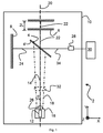
これから本発明による分光装置2の例示的実施形態を考察する。この装置は、図1および図2に示されているとおり、現在、マイケルソン型走査干渉計を構成するように配置されている。かかる走査干渉計の一般的動作原理はよく知られているので、ここでは本発明の理解のために必要な程度に限って詳しく説明することとする。例示した走査干渉計は、ビームスプリッター4(ここでは円形ビームスプリッター)および2個の反射器6、8(ここでは円形平面ミラーの形態)を備えている。ミラー6の1つは、2Lとして示されている距離にわたり相互並進できるように(両方向矢印で示されている)取り付けられ、他方のミラー8は固定されている。ビームスプリッター4は、本実施形態では、2個の反射器6、8とともに干渉計ハウジング10に収容されている。やはり例示装置2を構成しているのは、基準ビームを発生し、それをおおむね伝播経路14に沿って干渉計(4,6,8)のビームスプリッター4の第1の表面4’に向かって発射する単色光学放射源12(この基準ビームは追加光学素子により中断されない)および発散観測ビーム18を発生し、それをおおむね光源12とビームスプリッター4間の伝播経路20に沿って干渉計(4,6,8)のビームスプリッター4の第1表面4’に向かって発射する観測光学放射源16である(この観測ビーム18は、このビームの伝播方向すなわち伝播経路に影響を及ぼす追加光学素子を通過しない)。当然のことながら、本発明による装置のその他の実施形態が光源12、16とビームスプリッター4間に挿入されて伝播経路20、14のいずれかを変更する光学素子またはその他の構成要素を含む場合、本発明による伝播経路は、最後のかかる光学素子とビームスプリッター4間の該当ビームの伝播方向となる。用語「発射する」は、それに応じて解釈する。
Consider now an exemplary embodiment of a
周知のように、ビームスプリッター4は走査干渉計(4,6,8)の最初の要素と考えられ、入射ビームが透過ビーム経路22および反射ビーム経路24を通過する実質的に等しい強度のビームに分割されるように構築する。可動ミラー6は、それが相互に並進されたときに透過ビーム経路22をたどってビームスプリッター4に戻るビームを返すようにビームスプリッター4に対して相対的に位置づける。他方の固定ミラー8は、反射ビーム経路24をたどってビームスプリッター4に戻り、透過ビーム経路22をたどって帰還するビームと重なるビームを返すようにビームスプリッター4に相対的に位置づけられており、それによって基準ビーム光源12からの基準ビームおよび観察光源16からの観察ビーム18のそれぞれについてインターフェログラムが生成される。
As is well known, the
対応する基準ビームおよび観察ビームの放射検出器26、28も、それぞれ、分光装置2の一環として備えられている。基準ビーム放射検出器26は、干渉計ハウジング10に配置されており、基準ビーム経路36をたどる発射された基準ビームの反射成分から生成される基準インターフェログラムを検出する。観察ビーム放射検出器28は、同様に干渉計ハウジング10に配置されており、観測ビーム経路34をたどる発射された観測ビームの反射成分から生成される観測インターフェログラムを検出する。本発明の1つの実施形態に有益に従い、基準ビーム放射検出器26は、ビームスプリッター4から観測ビーム検出器28に向かってビーム経路34をたどる観測ビームの外側に配置することができる。これは、観測ビーム検出器28に入射する利用可能な放射を最大化することを可能とし、かつ、観測ビーム経路34および基準ビーム経路36のそれぞれの検出器28、26における空間フィルタリングを与える。この空間フィルタリング効果は、相手ビームからの光(すなわち基準検出器26に入射する観測ビームからの光およびその逆)により引き起こされるそれぞれの検出器28、26におけるバックグラウンド雑音が大幅に低減され、かつ、全く打ち消されることもあるので、有利である。
Corresponding reference beam and observation
基準ビームおよび観測ビームの検出器26、28は、この実施形態では、両方ともインターフェログラムハウジング10内に配置されるが、しかし、当然のことながら、これらのいずれかまたは両方ともハウジング10の外に配置し、たとえば適切な光ファイバーを用いてハウジング10と光学的に結合することもできる。同様に単色光学放射光源12と観測光学放射光源16の一方または両方もハウジング10の外に配置し、本出願において説明するように図1および図2に示すビーム経路をたどるようにそれと光学的に結合することもできる。
Reference beam and
適切にプログラムされたコンピュータ30のようなデータ処理装置を基準ビームおよび観測ビームの検出器26、28のそれぞれと動作可能なように接続し、検出されたそれぞれの基準インターフェログラムおよび観測インターフェログラムを表す信号を受信し、かつ、観測インターフェログラムからのスペクトル情報を得るために一般的には観測インターフェログラムをフーリエ解析することにより、これらの信号を処理することができる。本実施形態では、コンピュータ30は単一の装置として示されているが、しかし当然のことながら、この文脈におけるコンピュータは、所望の計算を自動的に行うために在来のプログラミングおよび電子技術を利用して構成された1つまたは複数の装置を意味するものと解するべきである。データ処理装置30を構成するかかる1つまたは複数の装置のいずれか1つまたは2つ以上をハウジング10と一体とするか、またはハウジング10の外部にローカル的に(図示されている固定接続経由)または遠隔通信的に(たとえば電気通信リンク、イントラネットまたはインターネット接続経由)設けることもできる。
An appropriately programmed data processing device such as a
分光装置2を光学分光学において使用する場合、透明または半透明のキュベットまたはその他のサンプル・ホルダ32を観測ビーム経路20に配置することができる。ここでは、それは、光源16とビームスプリッター4の第1表面4’間のビーム経路20の一般的方向を変えないように構成されている。本実施形態では、単なる例示にすぎないが、サンプル・ホルダ32はビームスプリッター4の前に(経路20沿いの観測ビーム18の伝播方向において)配置されているが、しかし、それはビームスプリッター4の後にまたは観測光学放射光源16もハウジングの外に配置される場合にはハウジング10の外のビームスプリッター4の前に配置することもできる。観測ビーム18の一定の波長は、他の波長より強くホルダ32中の試料物質と相互作用する。これにより、サンプル・ホルダ32中の物質の特性である観測ビーム18の強度の波長依存変動が生ずる。このスペクトル情報は、コンピュータ30においてたとえばフーリエ変換手段により、観測インターフェログラムのデコンボリューションから抽出することができる。
When the
この構成は、可動ミラー6が相互に並進されたときの基準ビームのビームスプリッター4越えの透過部分22の変位(ウォークオフ)が単色光学放射光源12および観測放射光源16の他の相対的方向づけと比較して最小化されるという利点を有する。しかし、当然のことながら、Y軸(この場合、伝播経路20に等しい)に関する光源12、16の他の相対的方向づけも請求される本発明から逸脱せずに使用できる。
In this configuration, the displacement (walk-off) of the
干渉計(4,6,8)の設計変数のすべてが独立に選択可能ではなく、図1および図2の干渉計2は、以下において論ずる設計基準を考慮して設計されることになる:
Not all of the design variables of the interferometer (4, 6, 8) are independently selectable, and the
この実施形態では、ビーム発散がビーム伝播の一般的方向20(ビームの中心またはビームパワー分布の最大の伝播方向により定められる)に関して対称となるように配向され、かつ、方向付けられる光源16から、先ずビームスプリッター4の第1表面4’に入射されるように干渉計(4,6,8)に発射される観測ビーム18を考察する。この観察ビーム18は、ビーム伝播のこの一般的方向20に対して発散半角、αを有する。これと同時に、基準ビームが干渉計(4,6,8)に対して基準ビーム経路14に沿って発射され、発散半角αを含む平面(ここでは、Z−X平面として示されている)に存在する観測ビーム18の伝播経路20に対する角、θをもってビームスプリッターの第1表面4’に先ず入射する。ここでは、本発明に従って、θ>αである。可動ミラー6の変位は、−Lと+Lの間で変化する。したがって、ミラー6の合計変位は、Ltot=2Lであり、レターデーションは−2Lと2Lの間で変化する。最大レターデーションは、δmax=2Lである。
In this embodiment, from a
干渉計(4,6,8)のレターデーションがゼロである場合、基準ビームの帰還成分は、ビームスプリッター4上に最大の重なりを有する。しかし、θはゼロではないので、基準ビームの帰還成分は、レターデーションの絶対値がゼロより上に増加する場合、ビームスプリッター4上でお互いに離れて行く。これがいわゆるウォークオフ効果である。最大絶対レターデーション、δmaxにおいて、帰還基準ビーム成分の中心間の距離は、次のとおりである:2Lsin(θ)=δmaxsin(θ) (2)
When the retardation of the interferometer (4, 6, 8) is zero, the feedback component of the reference beam has the largest overlap on the
基準インターフェログラムの振幅は、帰還基準ビームの2つの成分の電界強度分布の重なり積分により与えられるが、これは、dref>>δmaxsin(θ)の場合のみ、この振幅が一定となることを意味する。ただし、drefは、ビームスプリッター4上の帰還基準ビーム(すなわち、ミラー6とビームスプリッター4間の伝播経路22の部分を通過するビーム)の半値全幅(FWHM)である。電界強度の大きさの重なりは、2つの帰還ビーム成分がビームスプリッター4上で離れるので、ウォークオフ効果のために低減される。単色放射光源12は、単一空間モードおよびビームスプリッター4の第1表面4’上に位置するビームウエストを有する基準ビームを発生するレーザー光源とすることが好ましい。この方法により、基準ビームの位相面は実質的に平行となり、それにより空間コヒーレンスが最大となり、したがって許容ウォークオフも最大となる。
The amplitude of the reference interferogram is given by the overlap integral of the field strength distributions of the two components of the feedback reference beam, which is constant only when d ref >> δ max sin (θ). Means that. Here, d ref is the full width at half maximum (FWHM) of the feedback reference beam on the beam splitter 4 (that is, the beam passing through the portion of the
高い空間コヒーレンスを有する基準ビーム、たとえば単一モードまたは回折限界のビームが発生された場合、ビーム・ウォークオフは、主として基準インターフェログラムの振幅に影響を及ぼす。実際には、基準インターフェログラム上の一定の振幅包絡線は許容可能であり、帰還基準ビーム・サイズ、drefに関する要求条件は次のように緩和できる:dref>εδmaxsin(θ) (3)、ただしεは経験的に決定される定数であり、検出器26における信号対雑音比が、基準インターフェログラムから周期的に繰り返される特徴に基づいて行われる決定、一般的にゼロ交差決定を可能とするために十分となるように選択される。
When a reference beam with high spatial coherence, such as a single mode or diffraction limited beam, is generated, the beam walk-off primarily affects the amplitude of the reference interferogram. In practice, a constant amplitude envelope on the reference interferogram is acceptable, and the requirement on the feedback reference beam size, d ref can be relaxed as follows: d ref > εδ max sin (θ) ( 3) where ε is a constant determined empirically, and the determination that the signal-to-noise ratio at
図1および図2に示す本発明の特定の構成に関する経験から、また、単なる例示であるが、光学素子および構成における一般的な誤差を考慮するとε≒50が適当な値であることが見出された。たとえば、帰還基準ビーム・サイズがdref=2 mmかつθ=10度である場合、最大レターデーション、δmaxは、基準インターフェログラムの十分な振幅包絡線を維持するために0.23 mm未満とするべきである。 From experience with the particular configuration of the present invention shown in FIGS. 1 and 2, and by way of example only, it is found that ε≈50 is a reasonable value when considering general errors in the optical elements and configuration. It was done. For example, if the feedback reference beam size is d ref = 2 mm and θ = 10 degrees, the maximum retardation, δ max, is less than 0.23 mm to maintain a sufficient amplitude envelope of the reference interferogram Should be.
もう1つの重要な設計制約が観測ビーム18の発散半角、α、分光装置2の所要スペクトル解像度、Δυ、およびこの解像度Δυを実現するべき最大波数、υmaxの間に存在する。この解像度は、最大レターデーションに反比例する。これは、次のように定義できる:δmax=1/(Δυ) (4)、観測ビーム発散の上限は、次のように表すことができる:αmax=(δmaxυmax)−1/2 (5)
Another important design constraint exists between the divergence half-angle of the
したがって、たとえば、δmax=0.23 mm(上記のように)であり、かつ、一般的に最大波数υmax=3000 cm−1である場合、最大許容ビーム発散は、αmax=0.085 rad(すなわち4.9度)となる。この場合に得られる解像度は、22cm−1であり、−ミラーの運動により制限される。 Thus, for example, if δ max = 0.23 mm (as described above) and typically the maximum wavenumber υ max = 3000 cm −1 , the maximum allowable beam divergence is α max = 0.085. rad (ie, 4.9 degrees). The resolution obtained in this case is 22 cm −1 and is limited by the movement of the mirror.
上記の例は、ビームスプリッター4の第1表面4’における入射角θ(それは、観測ビーム発散半角、αより大きい)を有する基準ビームによる走査干渉計(4,6,8)を構成すること、およびそれでもやはりミラーの運動(レターデーション)により制限される解像度を得ることの可能性を示している。しかし、この種類の設計は、以下の考察からも分かるように、高い解像度を達成するには不利であろう:前述の例に従うと、基準ビームの入射角は、θ=1度に低減でき、2.2 cm−1の改善解像度に対応する2.3 mmの最大レターデーションを与える。しかし、観測ビーム発散の上限に関する要求条件は、αmax>θとなるために、ここでαmax=0.0027 rad(すなわち1.5度)となる。これは、図1および図2の設計が実現できないこと、または観測ビームの最大立体角が利用できないことを意味する。後者の場合、光エネルギー・スループットが低減されるが、これは、検出装置上の信号対雑音比を低下させる。
The above example constitutes a scanning interferometer (4, 6, 8) with a reference beam having an angle of incidence θ (which is greater than the observed beam divergence half angle, α) at the
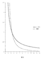
図3は、上述した2つの例を全体的に示すグラフである。x軸は、レーザー基準ビームの入射角および観測ビームの発散角を示し、y軸は、対応する最大レターデーションを示す。ただし、d=2 mmのレーザー・スポット・サイズおよびυmax=3000 cm−1の最大波数を前提とした。上述した低解像度および高解像度の設計は、点線で示されている。このプロットは、ここで使用したパラメータの場合、最大レターデーションが約1 mmより小さいときのみ、発散角より大きいレーザー(基準光源)入射角を有することが可能であることを示している。より大きいレターデーション、すなわちより高い解像度の場合、観測ビーム18の全立体角を活用することは不可能である。
FIG. 3 is a graph generally showing the two examples described above. The x-axis indicates the incident angle of the laser reference beam and the divergence angle of the observation beam, and the y-axis indicates the corresponding maximum retardation. However, a laser spot size of d = 2 mm and a maximum wave number of υ max = 3000 cm −1 were assumed. The low resolution and high resolution designs described above are shown as dotted lines. This plot shows that for the parameters used here, it is possible to have a laser (reference light source) incident angle greater than the divergence angle only when the maximum retardation is less than about 1 mm. For larger retardations, i.e. higher resolutions, it is impossible to exploit the full solid angle of the
本発明による干渉計2の正確度におけるもう1つの潜在的限界は、基準インターフェログラムの周期により与えられる波長の見掛けのずれである(単色基準ビームの物理的波長、λとの対比)。入射角θの場合、基準ビームのレターデーションは、cos(θ)−1の倍数であり、ミラー6の移動量より長い。したがって、基準インターフェログラムは、cos(θ)−1の倍数、基準ビームの入射角がゼロ度である場合より多くのゼロ交差(またはその他の周期的生起特徴)を含み、(cos(θ)・λ)の波長を有する光源のように見える。
Another potential limit in the accuracy of the
この干渉計の設計から、θは高い正確度で知られているので、この見掛けの波長のずれを補償する修正率は、容易に計算することができる。 Since θ is known with high accuracy from the design of this interferometer, the correction factor that compensates for this apparent wavelength shift can be easily calculated.
本発明の1つの実施形態において、この修正率は、コンピュータ30において観測インターフェログラムの標本抽出時刻を決定するときに使用される。
In one embodiment of the invention, this correction factor is used in the
既知固有波長特性を含むスペクトル・パターンを有する基準標本の測定に基づくインターフェログラムから抽出されたスペクトル情報の波長目盛を修正することは、たとえば米国特許出願公開第2008/0290279号明細書から知られている。その公表文献では、干渉計内の大気中のCO2に関係するスペクトル・パターンをこの目的のために利用し、観測インターフェログラムの1つの構成成分として記録する。したがって、本発明に従って、コンピュータ30内における波長目盛の修正は、基準標本からのスペクトル・パターンとビームスプリッター4における基準ビームの入射角θに依存する係数の一方または両方を使用して行うことができる。
Modifying the wavelength scale of spectral information extracted from an interferogram based on measurements of a reference sample having a spectral pattern that includes known intrinsic wavelength characteristics is known, for example, from US 2008/0290279. ing. In that publication, a spectral pattern related to atmospheric CO 2 in the interferometer is used for this purpose and is recorded as one component of the observed interferogram. Thus, according to the present invention, the correction of the wavelength scale in the
本発明による分光装置の別の例示実施形態38を図4に示す。分光装置38は、構造において図1に示した装置2に一般的に類似しており、ビームスプリッター40、固定ミラー42および可動ミラー44を備えており、これらは、図1の装置2に関連して前述したマイケルソン型干渉計配置に従って構成されている。本実施形態においては、ビームスプリッター40およびミラー42、44は、観測光放射源46(ここでは、発光源48および協働動作可能な凹面集束素子50を備えている)および基準放射光源52(単色レーザー放射光源などの)と同一平面上に配置されている。ここでは、放射光源46、52は、関連観測ビーム検出器54および基準ビーム放射検出器56(および、本実施形態において示されているようにサンプル・キュベット58および適切にプログラムされたコンピュータ30)とともに、ビームスプリッター40およびミラー42、44の配置されている干渉計ハウジング60の外部に配置されている。図2による本実施形態の1つの実現において、光源46、48および検出器54、56のうちの1つまたは複数を光ファイバ・ケーブルまたはその他の適切な導波管(示されていない)経由で干渉計ハウジングに光学的に結合し、分光装置38の構成をより柔軟にすることもできる。
Another
図1の装置2に関して述べたように、ここでも単色基準放射光源52は、基準ビームを発生し、それを干渉計ハウジング60内の伝播経路62に沿って発射する。この基準ビームは、伝播経路62における逸脱を引き起こす追加光学素子により中断されることなく、先ずビームスプリッター40の第1の表面40’に当たる。観測光放射源46により発生された発散観測ビーム64は、伝播経路66を通過し、基準ビームの存在するビームスプリッター40の第1表面40’に最初に当たる。干渉計(40,42,44)に向かって発射された観測ビーム64は、その伝播経路66に対して発散半角αを有しており、また、基準ビームの伝播経路62は、観測ビーム64の伝播経路66に対して角θをなすように形成されている。ただし、本発明に従ってθ>αである。
As described with respect to the
本発明の第2の実施形態による分光装置38は、次の設計パラメータに従って実現された:
The
観測光源46:ミラー50の焦点距離、f=14 mm、発光源48の直径、d=2 mm、発散角、2α=d/f=8.2°、発散半角、α=4.1°
Observation light source 46: focal length of
レーザー、単色基準光源52:入射角、θ=18° Laser, monochromatic reference light source 52: incident angle, θ = 18 °
干渉計40、42、44:最大最適レターデーション、δmax=2L=2*0.24 mm=0.048 mm、最大(観測)波数、υmax=3300 cm−1、解像度限界発散、αmax=(2*0.024*3300)−1/2=4.6°、ε=10を仮定する、それにより式(3)からdref=1.5 mm
したがって、本発明により要求されるようにαmax>αであり、また、レーザー・スポット・サイズは1.5 mmより大きい。 Therefore, α max > α as required by the present invention and the laser spot size is greater than 1.5 mm.
Claims (8)
前記観測ビームに試料物質を通過させるステップと、前記観測ビームから得た前記インターフェログラムを前記データ処理装置において処理して前記試料物質のスペクトル情報特性を抽出するステップとをさらに含むことを特徴とする方法。 The method of claim 5, wherein
Further comprising: passing a sample material through the observation beam; and processing the interferogram obtained from the observation beam in the data processing device to extract spectral information characteristics of the sample material. how to.
Applications Claiming Priority (3)
| Application Number | Priority Date | Filing Date | Title |
|---|---|---|---|
| EPPCT/EP2011/056934 | 2011-05-02 | ||
| EP2011056934 | 2011-05-02 | ||
| PCT/EP2012/057631 WO2012150172A1 (en) | 2011-05-02 | 2012-04-26 | Spectrometric instrument |
Publications (3)
| Publication Number | Publication Date |
|---|---|
| JP2014523517A JP2014523517A (en) | 2014-09-11 |
| JP2014523517A5 JP2014523517A5 (en) | 2014-10-23 |
| JP5714773B2 true JP5714773B2 (en) | 2015-05-07 |
Family
ID=46022220
Family Applications (1)
| Application Number | Title | Priority Date | Filing Date |
|---|---|---|---|
| JP2014508750A Active JP5714773B2 (en) | 2011-05-02 | 2012-04-26 | Spectrometer |
Country Status (16)
| Country | Link |
|---|---|
| US (1) | US8593637B2 (en) |
| JP (1) | JP5714773B2 (en) |
| KR (1) | KR101828100B1 (en) |
| CN (1) | CN102906535B (en) |
| AR (1) | AR089921A1 (en) |
| AU (1) | AU2012241106C1 (en) |
| BR (1) | BR112012028396B1 (en) |
| CA (1) | CA2791411C (en) |
| DK (1) | DK2564154T3 (en) |
| ES (1) | ES2436363T3 (en) |
| MX (1) | MX2013000643A (en) |
| PT (1) | PT2564154E (en) |
| RU (1) | RU2586393C2 (en) |
| UA (1) | UA111063C2 (en) |
| WO (1) | WO2012150172A1 (en) |
| ZA (1) | ZA201208023B (en) |
Families Citing this family (7)
| Publication number | Priority date | Publication date | Assignee | Title |
|---|---|---|---|---|
| US8766191B2 (en) * | 2009-10-06 | 2014-07-01 | The Curators Of The University Of Missouri | External/internal optical adapter for FTIR spectrophotometer |
| WO2015188255A1 (en) * | 2014-06-11 | 2015-12-17 | L&R Medical Inc. | Angular separation of scan channels |
| EP3254073B1 (en) * | 2015-02-02 | 2021-08-25 | FOSS Analytical A/S | A spectrometer system and a method for compensating for time periodic perturbations of an interferogram generated by the spectrometer system |
| JP2017191071A (en) * | 2016-04-15 | 2017-10-19 | キヤノン株式会社 | Spectroscopy data processing device, imaging device, spectroscopy data processing method and spectroscopy data processing program |
| CN111551520B (en) * | 2020-05-24 | 2021-04-27 | 清华大学 | Method and device for gas concentration multiplexing detection of cascade absorption path |
| CN112945385A (en) * | 2021-01-26 | 2021-06-11 | 同济大学 | Multi-reflection interference automatic measuring system |
| CN116297320B (en) * | 2023-05-09 | 2023-09-08 | 北京易兴元石化科技有限公司 | Near infrared spectrum system for coal quality analysis and coal quality analysis method |
Family Cites Families (20)
| Publication number | Priority date | Publication date | Assignee | Title |
|---|---|---|---|---|
| SU935716A1 (en) * | 1980-10-10 | 1982-06-15 | Предприятие П/Я Р-6681 | Interferential spectrometer |
| US4444501A (en) * | 1982-02-12 | 1984-04-24 | The United States Of America As Represented By The Secretary Of Commerce | Stabilization mechanism for optical interferometer |
| JPS63168522A (en) * | 1986-12-30 | 1988-07-12 | Shimadzu Corp | Adjuscting apparatus for interferometer |
| JPS63269024A (en) * | 1987-04-27 | 1988-11-07 | Fuji Electric Co Ltd | Interference spectroanalyzer |
| JPH0346523A (en) * | 1989-07-14 | 1991-02-27 | Sumitomo Electric Ind Ltd | Signal processor for fourier-transformation type spectroscope |
| JPH05231939A (en) * | 1992-02-21 | 1993-09-07 | Hitachi Ltd | Step scan fourier transferm infrared spectral apparatus |
| US5539518A (en) * | 1993-09-13 | 1996-07-23 | The United States Of America As Represented By The United States Department Of Energy | Method for determining and displaying the spacial distribution of a spectral pattern of received light |
| JPH07209085A (en) * | 1994-01-19 | 1995-08-11 | Yokogawa Electric Corp | Fourier spectrometer |
| JPH07286902A (en) * | 1994-04-18 | 1995-10-31 | Yokogawa Electric Corp | Fourier transform spectroscope |
| JP3314618B2 (en) * | 1996-06-24 | 2002-08-12 | 横河電機株式会社 | Moving mirror drive circuit |
| JPH11142243A (en) * | 1997-11-13 | 1999-05-28 | Yokogawa Electric Corp | Interferometer and fourier transform-type spectral apparatus using the same |
| DE10159721B4 (en) * | 2001-12-05 | 2004-07-22 | Bruker Optik Gmbh | Digital FTIR spectrometer |
| US6654125B2 (en) * | 2002-04-04 | 2003-11-25 | Inlight Solutions, Inc | Method and apparatus for optical spectroscopy incorporating a vertical cavity surface emitting laser (VCSEL) as an interferometer reference |
| JP2006528353A (en) * | 2003-07-18 | 2006-12-14 | ケミマジ コーポレーション | Method and apparatus for a multiwavelength imaging spectrometer |
| CN101084419A (en) | 2004-12-21 | 2007-12-05 | 福斯分析公司 | A method for standardising a spectrometer |
| JP2007114017A (en) * | 2005-10-19 | 2007-05-10 | Shimadzu Corp | Interferometer |
| EP2151248A1 (en) * | 2008-07-30 | 2010-02-10 | Johann Bauer | Improved pre-mRNA trans-splicing molecule (RTM) molecules and their uses |
| US7894072B1 (en) * | 2008-11-10 | 2011-02-22 | The United States Of America As Represented By The Secretary Of The Navy | Laser-based gas differential spectral analysis |
| US20120002210A1 (en) | 2009-04-28 | 2012-01-05 | Foss Analytical A/S | Optical interferometer |
| US8169616B2 (en) * | 2010-02-16 | 2012-05-01 | Agilent Technologies Australia (M) Pty Ltd | Interferometer step scanning systems and methods |
-
2012
- 2012-04-26 KR KR1020127028765A patent/KR101828100B1/en active IP Right Grant
- 2012-04-26 JP JP2014508750A patent/JP5714773B2/en active Active
- 2012-04-26 CA CA2791411A patent/CA2791411C/en active Active
- 2012-04-26 MX MX2013000643A patent/MX2013000643A/en active IP Right Grant
- 2012-04-26 AU AU2012241106A patent/AU2012241106C1/en active Active
- 2012-04-26 BR BR112012028396-0A patent/BR112012028396B1/en active IP Right Grant
- 2012-04-26 CN CN201280001217.3A patent/CN102906535B/en active Active
- 2012-04-26 PT PT127176808T patent/PT2564154E/en unknown
- 2012-04-26 US US13/583,534 patent/US8593637B2/en active Active
- 2012-04-26 DK DK12717680.8T patent/DK2564154T3/en active
- 2012-04-26 RU RU2012142137/28A patent/RU2586393C2/en active
- 2012-04-26 UA UAA201211606A patent/UA111063C2/en unknown
- 2012-04-26 ES ES12717680T patent/ES2436363T3/en active Active
- 2012-04-26 WO PCT/EP2012/057631 patent/WO2012150172A1/en active Application Filing
- 2012-10-24 ZA ZA2012/08023A patent/ZA201208023B/en unknown
-
2013
- 2013-02-06 AR ARP130100370A patent/AR089921A1/en active IP Right Grant
Also Published As
| Publication number | Publication date |
|---|---|
| CA2791411A1 (en) | 2012-11-02 |
| AU2012241106C1 (en) | 2014-01-16 |
| CA2791411C (en) | 2017-03-21 |
| CN102906535B (en) | 2016-01-20 |
| US20130188192A1 (en) | 2013-07-25 |
| ZA201208023B (en) | 2014-01-29 |
| JP2014523517A (en) | 2014-09-11 |
| DK2564154T3 (en) | 2013-11-18 |
| AR089921A1 (en) | 2014-10-01 |
| WO2012150172A1 (en) | 2012-11-08 |
| UA111063C2 (en) | 2016-03-25 |
| RU2586393C2 (en) | 2016-06-10 |
| KR20140022715A (en) | 2014-02-25 |
| NZ602603A (en) | 2014-06-27 |
| AU2012241106A1 (en) | 2012-11-22 |
| BR112012028396A2 (en) | 2018-10-16 |
| RU2012142137A (en) | 2014-10-10 |
| ES2436363T3 (en) | 2013-12-30 |
| AU2012241106B2 (en) | 2013-07-18 |
| CN102906535A (en) | 2013-01-30 |
| PT2564154E (en) | 2013-12-05 |
| KR101828100B1 (en) | 2018-02-09 |
| MX2013000643A (en) | 2013-03-22 |
| BR112012028396B1 (en) | 2021-02-02 |
| US8593637B2 (en) | 2013-11-26 |
Similar Documents
| Publication | Publication Date | Title |
|---|---|---|
| JP5714773B2 (en) | Spectrometer | |
| EP2634551B1 (en) | Interferometer and fourier-transform spectroscopic analyzer | |
| JP5635624B2 (en) | Compact interference spectrometer | |
| JP5835327B2 (en) | Interferometer and spectrometer equipped with the interferometer | |
| WO2008083492A1 (en) | Two-beam interferometer for fourier transform spectroscopy with double pivot scanning mechanism | |
| US20180113026A1 (en) | Fourier transform spectroscope | |
| WO2012073681A1 (en) | Laser light source, interferometer and spectrometer | |
| US20130215435A1 (en) | Measuring unit, measuring system and method for determining a relative position and relative orientation | |
| WO2020202547A1 (en) | Optical distance measurement device | |
| WO2011148726A1 (en) | Interferometer, and fourier transform spectrometry device | |
| JP5974929B2 (en) | Stray light correction method and Fourier transform type spectroscopic device using the same | |
| EP2564154B1 (en) | Spectrometric instrument | |
| Jin et al. | A concept of multi-mode high spectral resolution lidar using Mach-Zehnder interferometer | |
| WO2010088023A2 (en) | Mirror-tilt-insensitive fourier transform spectrometer | |
| WO2019202761A1 (en) | Spectrometer, imaging device, scanning device, and position measuring device | |
| NZ602603B2 (en) | Spectrometric instrument | |
| JP2006284233A (en) | Apparatus for measuring system error and interferometer system for wavefront measurement equipped with the same | |
| JP2006300664A (en) | Fourier spectral device and measuring timing detection method | |
| JPWO2019008964A1 (en) | Interferometer, Fourier transform spectrometer and component analyzer |
Legal Events
| Date | Code | Title | Description |
|---|---|---|---|
| A521 | Request for written amendment filed |
Free format text: JAPANESE INTERMEDIATE CODE: A523 Effective date: 20140604 |
|
| A521 | Request for written amendment filed |
Free format text: JAPANESE INTERMEDIATE CODE: A523 Effective date: 20140729 |
|
| A621 | Written request for application examination |
Free format text: JAPANESE INTERMEDIATE CODE: A621 Effective date: 20140729 |
|
| A871 | Explanation of circumstances concerning accelerated examination |
Free format text: JAPANESE INTERMEDIATE CODE: A871 Effective date: 20140729 |
|
| A975 | Report on accelerated examination |
Free format text: JAPANESE INTERMEDIATE CODE: A971005 Effective date: 20140918 |
|
| A131 | Notification of reasons for refusal |
Free format text: JAPANESE INTERMEDIATE CODE: A131 Effective date: 20140924 |
|
| TRDD | Decision of grant or rejection written | ||
| A01 | Written decision to grant a patent or to grant a registration (utility model) |
Free format text: JAPANESE INTERMEDIATE CODE: A01 Effective date: 20150217 |
|
| A61 | First payment of annual fees (during grant procedure) |
Free format text: JAPANESE INTERMEDIATE CODE: A61 Effective date: 20150311 |
|
| R150 | Certificate of patent or registration of utility model |
Ref document number: 5714773 Country of ref document: JP Free format text: JAPANESE INTERMEDIATE CODE: R150 |
|
| R250 | Receipt of annual fees |
Free format text: JAPANESE INTERMEDIATE CODE: R250 |
|
| R250 | Receipt of annual fees |
Free format text: JAPANESE INTERMEDIATE CODE: R250 |
|
| R250 | Receipt of annual fees |
Free format text: JAPANESE INTERMEDIATE CODE: R250 |
|
| R250 | Receipt of annual fees |
Free format text: JAPANESE INTERMEDIATE CODE: R250 |
|
| R250 | Receipt of annual fees |
Free format text: JAPANESE INTERMEDIATE CODE: R250 |
|
| R250 | Receipt of annual fees |
Free format text: JAPANESE INTERMEDIATE CODE: R250 |
|
| R250 | Receipt of annual fees |
Free format text: JAPANESE INTERMEDIATE CODE: R250 |