JP5713058B2 - Method for producing metal porous body - Google Patents
Method for producing metal porous body Download PDFInfo
- Publication number
- JP5713058B2 JP5713058B2 JP2013146038A JP2013146038A JP5713058B2 JP 5713058 B2 JP5713058 B2 JP 5713058B2 JP 2013146038 A JP2013146038 A JP 2013146038A JP 2013146038 A JP2013146038 A JP 2013146038A JP 5713058 B2 JP5713058 B2 JP 5713058B2
- Authority
- JP
- Japan
- Prior art keywords
- carrier sheet
- convex
- foamable slurry
- metal
- slurry
- Prior art date
- Legal status (The legal status is an assumption and is not a legal conclusion. Google has not performed a legal analysis and makes no representation as to the accuracy of the status listed.)
- Expired - Fee Related
Links
Images


Classifications
-
- Y—GENERAL TAGGING OF NEW TECHNOLOGICAL DEVELOPMENTS; GENERAL TAGGING OF CROSS-SECTIONAL TECHNOLOGIES SPANNING OVER SEVERAL SECTIONS OF THE IPC; TECHNICAL SUBJECTS COVERED BY FORMER USPC CROSS-REFERENCE ART COLLECTIONS [XRACs] AND DIGESTS
- Y02—TECHNOLOGIES OR APPLICATIONS FOR MITIGATION OR ADAPTATION AGAINST CLIMATE CHANGE
- Y02E—REDUCTION OF GREENHOUSE GAS [GHG] EMISSIONS, RELATED TO ENERGY GENERATION, TRANSMISSION OR DISTRIBUTION
- Y02E60/00—Enabling technologies; Technologies with a potential or indirect contribution to GHG emissions mitigation
- Y02E60/30—Hydrogen technology
- Y02E60/50—Fuel cells
-
- Y—GENERAL TAGGING OF NEW TECHNOLOGICAL DEVELOPMENTS; GENERAL TAGGING OF CROSS-SECTIONAL TECHNOLOGIES SPANNING OVER SEVERAL SECTIONS OF THE IPC; TECHNICAL SUBJECTS COVERED BY FORMER USPC CROSS-REFERENCE ART COLLECTIONS [XRACs] AND DIGESTS
- Y02—TECHNOLOGIES OR APPLICATIONS FOR MITIGATION OR ADAPTATION AGAINST CLIMATE CHANGE
- Y02P—CLIMATE CHANGE MITIGATION TECHNOLOGIES IN THE PRODUCTION OR PROCESSING OF GOODS
- Y02P70/00—Climate change mitigation technologies in the production process for final industrial or consumer products
- Y02P70/50—Manufacturing or production processes characterised by the final manufactured product
Description
本発明は、面方向に密度分布を有する金属多孔質体の製造方法に関する。 The present invention relates to a method for producing a porous metal body having a density distribution in the plane direction.
固体高分子型燃料電池において、空気極側での反応で生じる水が滞留して空気(酸化剤ガス)の流通を妨げることにより反応効率が低下したり停止したりすること(いわゆるフラッディング)を防止するために、燃料電池内の水を速やかに排出できる構造が検討されている。 In polymer electrolyte fuel cells, water generated by the reaction at the air electrode side is prevented from staying and preventing the flow of air (oxidant gas) from decreasing or stopping (so-called flooding). In order to achieve this, a structure capable of quickly discharging water in the fuel cell has been studied.
たとえば特許文献1では、発泡焼結金属によって形成した集電板に複数の貫通孔を設けることにより、空気電極層側において発生した水(生成水)を発泡空孔で毛管現象により吸引するとともに、貫通孔を通じて酸化剤ガスを電解質膜に供給することが提案されている。この場合、発泡空孔で吸引された生成水は貫通孔内で蒸発して、余分の酸化剤ガスとともにこの貫通孔を通じて集電板から排出される。
また特許文献2では、燃料電池のガス拡散層において、触媒層に接する面に排水用の溝を設けることにより、フラッディングを防止している。
For example, in Patent Document 1, by providing a plurality of through holes in a current collector plate formed of foamed sintered metal, water (generated water) generated on the air electrode layer side is sucked by capillarity in the foam holes, It has been proposed to supply oxidant gas to the electrolyte membrane through the through-hole. In this case, the generated water sucked in the foaming holes evaporates in the through holes, and is discharged from the current collector plate through the through holes together with excess oxidant gas.
Further, in Patent Document 2, flooding is prevented by providing a drainage groove on the surface in contact with the catalyst layer in the gas diffusion layer of the fuel cell.
特許文献3では、金属質の多孔質体の板材に対して型彫り放電加工による除去加工を行って板厚の異なる部分を形成し、板厚が大きい部分を圧延することにより高密度化することが提案されている。この場合、金属多孔質体の面方向に任意の空隙率分布を形成できる。
しかしながら、特許文献1の集電板では、酸化剤の供給量を増大させる場合は多くの貫通孔を設けなければならないため、強度が低下するおそれがある。特許文献2のガス拡散層では、溝を形成したことによって触媒層に対する接触面積が小さくなり、電気抵抗が増大して発電効率を低下させるおそれがある。特許文献3の方法では、金属多孔質体に対して除去加工を行っているため、加工層の生成による目詰まり等により多孔質材の流通性を低下させるおそれがあるとともに、表面が荒れるために接触する相手部材(たとえば特許文献1における電解質膜)を損傷するおそれがある。また、放電加工等の除去加工は手間がかかり、製造コストが増大するという問題がある。 However, in the current collector plate of Patent Document 1, when increasing the supply amount of the oxidant, a large number of through holes must be provided, which may reduce the strength. In the gas diffusion layer of Patent Document 2, since the groove is formed, the contact area with the catalyst layer is reduced, and there is a possibility that the electric resistance is increased and the power generation efficiency is lowered. In the method of Patent Document 3, since the removal processing is performed on the metal porous body, the flowability of the porous material may be reduced due to clogging due to the generation of the processed layer, and the surface is roughened. There is a risk of damaging a mating member (for example, the electrolyte membrane in Patent Document 1) that comes into contact. In addition, removal processing such as electric discharge machining is troublesome and there is a problem that the manufacturing cost increases.
本発明は、このような事情に鑑みてなされたもので、面方向に空隙率分布を有し、強度が高く、流体の流通性に優れた金属多孔質体を提供することを目的とする。 The present invention has been made in view of such circumstances, and an object thereof is to provide a porous metal body having a porosity distribution in the surface direction, high strength, and excellent fluidity.
本発明は、金属焼結体の骨格により辺が構成されてなる複数の多面体状の空隙が相互に連続状態に形成されている板状の金属多孔質体の製造方法であって、金属粉末と発泡剤とを含有する発泡性スラリーを、キャリヤシート上に塗布し、前記キャリヤシートを移動させながら前記発泡性スラリーを薄板状に成形する成形工程と、薄板状に成形した発泡性スラリーを発泡および乾燥させてグリーンシートを形成する発泡乾燥工程と、前記グリーンシートを焼結して焼結体を形成する焼結工程と、前記焼結体を所定の厚さとなるまで厚さ方向に圧縮する圧縮工程と、を有し、前記成形工程において前記キャリヤシート上の前記発泡性スラリーの表裏面の少なくとも一方に凸部および凹部を形成することにより、前記グリーンシートの表裏面の少なくとも一方に凸部および凹部を形成し、このグリーンシートを焼結することにより前記焼結体の表裏面の少なくとも一方に凸部および凹部を形成し、前記圧縮工程において前記焼結体の少なくとも前記凸部の厚さが小さくなるように圧縮することにより、前記骨格の間に形成される空隙の空隙率が面方向に異なり、高密度部と低密度部とが面方向に交互に配列されている金属多孔質体を製造し、前記圧縮工程前の前記焼結体において、前記空隙率は60%以上99%以下、前記凸部と前記凹部との厚さの差は20μm以上3mm以下、前記圧縮工程後の前記金属多孔質体において、前記空隙率は50%以上98%以下、前記最外面における前記空隙の開口率は5%以上99%以下、前記最外面における前記空隙の平均開口径は30μm以上1mm以下とする。 The present invention is a method for producing a plate-like metal porous body in which a plurality of polyhedral voids whose sides are constituted by a skeleton of a metal sintered body is formed in a continuous state, and a metal powder and A foaming slurry containing a foaming agent is applied onto a carrier sheet, and the foaming slurry is formed into a thin plate shape while moving the carrier sheet, and the foamable slurry formed into a thin plate shape is foamed and foamed. A foam drying process for forming a green sheet by drying, a sintering process for forming a sintered body by sintering the green sheet, and a compression for compressing the sintered body in a thickness direction until a predetermined thickness is achieved. And forming a convex portion and a concave portion on at least one of the front and back surfaces of the foamable slurry on the carrier sheet in the molding step, thereby reducing the front and back surfaces of the green sheet. In both cases, a convex portion and a concave portion are formed on one side, and the green sheet is sintered to form a convex portion and a concave portion on at least one of the front and back surfaces of the sintered body. by compressing so that the thickness of the protrusion is reduced, the porosity of the gap formed between the skeleton varies in the plane direction, and the high density portion and a low-density portion are arranged alternately in the plane direction In the sintered body before the compression step, the porosity is 60% or more and 99% or less, and the thickness difference between the projection and the recess is 20 μm or more and 3 mm or less, In the metal porous body after the compression step, the porosity is 50% or more and 98% or less, the opening ratio of the void on the outermost surface is 5% or more and 99% or less, and the average opening diameter of the voids on the outermost surface. Is more than 30μm and 1m Below that.
この方法によれば、凸部および凹部を有する焼結体を所定の厚さに圧縮することにより、凹部を圧縮した部分に比較して凸部を圧縮した部分の空隙率が小さくなるので、面方向に密度分布を有する金属多孔質体を得ることができる。また、焼結体に除去加工を施して凸部および凹部を形成する場合には加工層の生成による目詰まりや表面の荒れが生じるおそれがあるが、本発明では焼結前に凸部および凹部を形成しているので、凸部および凹部を有する面を金属焼結体の骨格の側面により形成でき、加工層や表面の荒れが生じるおそれがない。
圧縮工程前において、空隙率を60%以上としたのは内部の流体流通性を確保するためであり、空隙率を99%以下としたのは金属多孔質体の強度を確保するためである。
また、前記圧縮工程前の前記焼結体において、前記凸部と前記凹部との厚さの差が20μm以上3mm以下とすることにより、凸部および凹部の強度を確保することができる。
また、前記金属多孔質体の前記最外面における前記空隙の開口率が5%以上99%以下、前記金属多孔質体の前記最外面における前記空隙の平均開口径が30μm以上1mm以下とすることにより、内部の空隙への入口面積を確保でき、かつ金属多孔質体の強度を確保できる。
なお、この製造方法によって、凹部を圧縮しないように焼結体を圧縮することにより、圧縮後においても凸部の厚さが凹部の厚さよりも大きい金属多孔質体と、凹部を圧縮しないように焼結体を圧縮することにより、圧縮後の凸部の厚さが圧縮前の凹部の厚さと等しく、圧縮後の全体の厚さが均一である金属多孔質体と、焼結体を圧縮する際に凸部だけでなく凹部も圧縮することにより、圧縮後の全体の厚さが均一である金属多孔質体と、の3通りの金属多孔質体を製造することができる。
According to this method, by compressing the sintered body having the convex portion and the concave portion to a predetermined thickness, the porosity of the portion where the convex portion is compressed becomes smaller than the portion where the concave portion is compressed. A porous metal body having a density distribution in the direction can be obtained. In addition, when forming a convex portion and a concave portion by performing removal processing on the sintered body, there is a possibility that clogging or surface roughness may occur due to generation of a processed layer. Therefore, the surface having the convex part and the concave part can be formed by the side face of the skeleton of the sintered metal body, and there is no possibility that the processed layer and the surface are roughened.
The reason why the porosity is set to 60% or more before the compression step is to ensure the internal fluid flowability, and the reason why the porosity is set to 99% or less is to ensure the strength of the metal porous body.
Moreover, in the sintered body before the compression step, the strength of the convex portion and the concave portion can be ensured by setting the difference in thickness between the convex portion and the concave portion to 20 μm or more and 3 mm or less.
Further, the opening ratio of the voids on the outermost surface of the metal porous body is 5% or more and 99% or less, and the average opening diameter of the voids on the outermost surface of the metal porous body is 30 μm or more and 1 mm or less. In addition, the area of the entrance to the internal void can be secured, and the strength of the metal porous body can be secured.
In addition, by compressing a sintered compact so that a recessed part may not be compressed with this manufacturing method, the thickness of a convex part is larger than the thickness of a recessed part after compression, and a recessed part is not compressed. By compressing the sintered body, the thickness of the convex portion after compression is equal to the thickness of the concave portion before compression, and the whole thickness after compression is uniform, and the sintered body is compressed. In this case, by compressing not only the convex portions but also the concave portions, three types of metal porous bodies can be manufactured: a metal porous body having a uniform overall thickness after compression.
この製造方法において、前記キャリヤシート上の前記発泡性スラリーの上面に、先端面に凹凸形状を有するブレードの前記先端面を接触させることにより、前記発泡性スラリーに前記凸部および凹部を形成することが好ましい。この場合、凹凸形状を有するブレードで発泡性スラリーの表面を掻き取るように成形することにより、焼結前のグリーンシートに凸部および凹部を形成することができる。
また、この金属多孔質体の製造方法において、前記キャリヤシート上に塗布された前記発泡性スラリーの上面に、表面に凹凸形状を有する転写用ローラの前記表面を押しつけることにより、前記発泡性スラリーに前記凸部および凹部を形成してもよい。また、この金属多孔質体の製造方法において、前記キャリヤシートに凹凸形状を設けておき、前記キャリヤシート上の前記発泡性スラリーに前記凸部および凹部を形成してもよい。この場合も、焼結前のグリーンシートに凸部および凹部を形成することができる。
In this manufacturing method, the convex portion and the concave portion are formed in the foamable slurry by bringing the top surface of the blade having a concavo-convex shape into contact with the top surface of the foamable slurry on the carrier sheet. Is preferred. In this case, a convex part and a concave part can be formed on the green sheet before sintering by shaping the surface of the foamable slurry to be scraped off with a blade having an uneven shape.
Further, in this method for producing a porous metal body, the foaming slurry is pressed onto the upper surface of the foaming slurry applied on the carrier sheet by pressing the surface of the transfer roller having an uneven shape on the surface. You may form the said convex part and a recessed part. Further, in this method for producing a metal porous body, the carrier sheet may be provided with a concavo-convex shape, and the convex portion and the concave portion may be formed in the foamable slurry on the carrier sheet. Also in this case, a convex part and a recessed part can be formed in the green sheet before sintering.
あるいは、前記キャリヤシートの下面に当接する下ローラと、この下ローラに対して前記キャリヤシートを介して間隔をあけたブレードとを配置しておき、前記成形工程において、前記下ローラの表面と前記ブレードの先端面との間隔を変化させながら前記ブレードの前記先端面と前記下ローラの前記表面との間から前記キャリヤシートとともに前記発泡性スラリーを引き出すことにより、この発泡性スラリーの成形厚さを変化させて前記凸部および凹部を形成することが好ましい。
この製造方法によれば、下ローラの表面とブレードの先端面との間隔がキャリヤシート上の発泡性スラリーの厚さを決定するので、この間隔を変化させながらキャリヤシートを移動させることによって任意の形状の凸部および凹部を有する金属多孔質体を製造することができる。焼結前に凸部および凹部を形成することにより、表面を金属焼結体の骨格の側面によって滑らかに形成できるので、隣接する部材を損傷しない金属多孔質体を製造することができる。
Alternatively, a lower roller that contacts the lower surface of the carrier sheet and a blade that is spaced from the lower roller via the carrier sheet are arranged, and in the molding step, the surface of the lower roller and the By pulling out the foamable slurry together with the carrier sheet from between the front end surface of the blade and the surface of the lower roller while changing the distance from the front end surface of the blade, the molding thickness of the foamable slurry is reduced. It is preferable to change and form the said convex part and a recessed part.
According to this manufacturing method, since the distance between the surface of the lower roller and the tip surface of the blade determines the thickness of the foamable slurry on the carrier sheet, the carrier sheet is moved by moving the carrier sheet while changing the distance. A porous metal body having convex and concave portions can be produced. By forming the convex part and the concave part before sintering, the surface can be smoothly formed by the side face of the skeleton of the metal sintered body, and therefore a metal porous body that does not damage adjacent members can be produced.
この製造方法において、前記下ローラの前記表面に凹凸形状を設けておくことにより、前記成形工程において前記下ローラの前記表面と前記ブレードの前記先端面との間隔を変化させて前記凸部および凹部を形成することが好ましい。この場合、下ローラの表面の凹凸形状に従って、下ローラとブレードとの間隔を変化させることができる。
また、この製造方法において、前記下ローラを偏心回転させることにより、前記成形工程において前記下ローラの前記表面と前記ブレードの前記先端面との間隔を変化させて前記凸部および凹部を形成してもよい。
また、この製造方法において、前記ブレードおよび前記下ローラの少なくとも一方を他方に向けて往復移動させることにより、前記成形工程において前記下ローラの前記表面と前記ブレードの前記先端面との間隔を変化させて前記凸部および凹部を形成してもよい。
In this manufacturing method, by providing a concavo-convex shape on the surface of the lower roller, in the molding step, the distance between the surface of the lower roller and the tip end surface of the blade is changed, so that the convex portion and the concave portion are formed. Is preferably formed. In this case, the distance between the lower roller and the blade can be changed according to the uneven shape on the surface of the lower roller.
Further, in this manufacturing method, by rotating the lower roller eccentrically, the convex portion and the concave portion are formed by changing the distance between the surface of the lower roller and the tip surface of the blade in the molding step. Also good.
Further, in this manufacturing method, at least one of the blade and the lower roller is reciprocated toward the other, thereby changing a distance between the surface of the lower roller and the tip surface of the blade in the molding step. The convex portion and the concave portion may be formed.
本発明の金属多孔質体の製造方法によれば、金属焼結体の骨格を分断せずに凸部および凹部を形成できるので、隣接する他部材を損傷させず、燃料電池の構成部材としても用いることができる金属多孔質体を製造することができる。 According to the method for producing a porous metal body of the present invention, since the convex portion and the concave portion can be formed without dividing the skeleton of the sintered metal body, the adjacent members are not damaged, and can be used as a constituent member of the fuel cell. The metal porous body which can be used can be manufactured.
以下、本発明に係る金属多孔質体の製造方法の実施形態について説明する。本発明の製造方法では、凸部10aおよび凹部10bを有する板状の焼結体10(図1)を厚さ方向に圧縮することにより、面方向に密度分布を有する金属多孔質体13(図2)を製造する。
Hereinafter, an embodiment of a method for producing a metal porous body according to the present invention will be described. In the manufacturing method of the present invention, the plate-like sintered body 10 (FIG. 1) having the
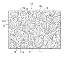
図1に示すように、焼結体10は、厚さh1の凸部10aおよび厚さh2の凹部10bが交互に面方向に交互に配列された板状の部材である。この焼結体10において、最大厚さ(すなわち凸部10aの厚さ)h1と最小厚さ(すなわち凹部10bの厚さ)h2との差は、20μm以上3mm以下(本実施形態では300μm)である。より具体的には、本実施形態の焼結体10の凸部10aの厚さh1は600μm、凹部10bの厚さh2は300μmであり、その差は300μmである。
As shown in FIG. 1, the sintered
この焼結体10は、金属焼結体の骨格11により辺が構成されてなる複数の多面体状の空隙12が相互に連続状態に形成されていて、その表裏面の最外面は、図3に示すように骨格11の側面で形成されている。
In this
空隙12は、骨格11により辺が構成された複数の多面体状のポア(気孔)が相互に連続するように形成されており、焼結体10の体積中、60%以上99%以下(本実施形態では80%)を占めている。以下、この空隙12全体の体積割合を空隙率と呼ぶ。空隙率は、同形の中実体の重量に対する実測重量から算出する。
The
空隙12は、焼結体10の表面に開口する複数の開口部12aを有しており、その開口面積は表面の面積のうち5%以上99%以下(本実施形態では80%)を占めている。以下、この表面における空隙12の開口面積の割合を開口率と呼ぶ。開口率は、焼結体10
の表面を撮影した25〜100倍顕微鏡写真を用いて、視野面積Aと、この視野中の最外面の全ての開口部12aの面積和Apとを測定し、次の式によって算出する。
開口率(%)=Ap/A×100
The
The field area A and the area sum Ap of all the
Opening ratio (%) = Ap / A × 100
また、この開口部12aの平均開口サイズは、開口部12aを円形とみなした場合の直径が30μm以上1mm以下(本実施形態では120μm)であり、以下、これを平均開口径と呼ぶ。平均開口径は、25〜100倍顕微鏡写真において、視野中の最外面の各開口部12aの面積を測定して算出した各円相当径の算術平均である。
The average opening size of the
この焼結体10を全体の厚さが280μmとなるまで面方向に圧縮すると、凸部10aおよび凹部10bの空隙率はそれぞれ57%、79%となり、図2に示すように高密度部10cと低密度部10dとが面方向に交互に配列された金属多孔質体13が得られる。
When this sintered
ここで、凸部および凹部を有するグリーンシートおよび焼結体10の製造方法について説明する。
〈発泡性スラリー作成工程〉
まず、金属粉末と発泡剤とを含有する発泡性スラリーSを作成する。発泡性スラリーSは、骨格11を形成する金属粉末、バインダ(水溶性樹脂結合剤)、発泡剤および水と、必要に応じて界面活性剤および/または可塑剤とを混合することにより作成される。より具体的には、まず金属粉末、バインダおよび水を含有するスラリーを作成した後、このスラリーに発泡剤を添加し、ミキサーなどの攪拌装置で攪拌する。
Here, the manufacturing method of the green sheet and the sintered compact 10 which have a convex part and a recessed part is demonstrated.
<Foaming slurry preparation process>
First, a foamable slurry S containing metal powder and a foaming agent is prepared. The foamable slurry S is prepared by mixing a metal powder forming a
金属粉末としては、特に限定されないが、耐食性等の点から、Ni,Cu,Ti,Al,Ag,ステンレス鋼等が好ましい。また、この金属粉末は平均粒径0.5μm以上30μm以下が好ましい。このような粉末は、水アトマイズ法,プラズマアトマイズ法などのアトマイズ法、酸化物還元法,湿式還元法,カルボニル反応法などの化学プロセス法によって製造することができる。 Although it does not specifically limit as metal powder, Ni, Cu, Ti, Al, Ag, stainless steel, etc. are preferable from points, such as corrosion resistance. The metal powder preferably has an average particle size of 0.5 μm or more and 30 μm or less. Such a powder can be produced by an atomizing method such as a water atomizing method or a plasma atomizing method, a chemical process method such as an oxide reduction method, a wet reduction method, or a carbonyl reaction method.
バインダ(水溶性樹脂結合剤)としては、メチルセルロース,ヒドロキシプロピルメチルセルロース,ヒドロキシエチルメチルセルロース,カルボキシメチルセルロースアンモニウム,エチルセルロース,ポリビニルアルコールなどを使用することができる。 As the binder (water-soluble resin binder), methylcellulose, hydroxypropylmethylcellulose, hydroxyethylmethylcellulose, carboxymethylcellulose ammonium, ethylcellulose, polyvinyl alcohol, and the like can be used.
発泡剤は、ガスを発生してスラリーに気泡を形成できるものであればよく、揮発性有機溶剤、例えば、ペンタン,ネオペンタン,ヘキサン,イソヘキサン,イソペプタン,ベンゼン,オクタン,トルエンなどの炭素数5〜8の非水溶性炭化水素系有機溶剤を使用することができる。この発泡剤の含有量としては、発泡性スラリーSに対して0.1〜5重量%とすることが好ましい。 The foaming agent is not particularly limited as long as it can generate gas and form bubbles in the slurry, and is a volatile organic solvent such as pentane, neopentane, hexane, isohexane, isopeptane, benzene, octane, toluene, etc. The water-insoluble hydrocarbon-based organic solvent can be used. The foaming agent content is preferably 0.1 to 5% by weight with respect to the foamable slurry S.
界面活性剤としては、アルキルベンゼンスルホン酸塩,α‐オレフィンスルホン酸塩,アルキル流酸エステル塩,アルキルエーテル硫酸エステル塩,アルカンスルホン酸塩等のアニオン界面活性剤,ポリエチレングリコール誘導体,多価アルコール誘導体などの非イオン性界面活性剤および両性界面活性剤などを使用することができる。 Surfactants include anionic surfactants such as alkylbenzene sulfonate, α-olefin sulfonate, alkyl sulfonate, alkyl ether sulfate, alkane sulfonate, polyethylene glycol derivatives, polyhydric alcohol derivatives, etc. Nonionic surfactants and amphoteric surfactants can be used.
可塑剤は、スラリーを成形して得られる成形体に可塑性を付与するために添加され、例えばエチレングリコール,ポリエチレングリコール,グリセリンなどの多価アルコール、鰯油,菜種油,オリーブ油などの油脂、石油エーテルなどのエーテル類、フタル酸ジエチル,フタル酸ジNブチル,フタル酸ジエチルヘキシル,フタル酸ジオクチル,ソルビタンモノオレート,ソルビタントリオレート,ソルビタンパルミテート,ソルビタンステアレートなどのエステル等を使用することができる。 The plasticizer is added to impart plasticity to a molded product obtained by molding a slurry. For example, polyhydric alcohols such as ethylene glycol, polyethylene glycol, and glycerin, fats and oils such as coconut oil, rapeseed oil, and olive oil, petroleum ether, etc. Ethers such as diethyl phthalate, di-N-butyl phthalate, diethyl hexyl phthalate, dioctyl phthalate, sorbitan monooleate, sorbitan trioleate, sorbitan palmitate, sorbitan stearate, and the like can be used.
さらに、スラリーの特性や成形性を向上させるために任意の添加成分を加えてもよい。例えば、防腐剤を添加してスラリーの保存性を向上させたり、結合助材としてポリマー系化合物を加えて成形体の強度を向上させたりすることができる。 Furthermore, an optional additive component may be added to improve the properties and moldability of the slurry. For example, a preservative can be added to improve the storage stability of the slurry, or a polymer compound can be added as a binding aid to improve the strength of the molded body.
このように作成した発泡性スラリーSから、図4に示す成形装置20を用いて、グリーンシートを形成する成形工程および発泡乾燥工程を行う。
〈成形工程〉
成形装置20は、ドクターブレード法を用いてシートを形成する装置であり、発泡性スラリーSが貯留されるホッパ21、ホッパ21から供給された発泡性スラリーSを移送するキャリヤシート22、キャリヤシート22を支持するローラ23、キャリヤシート22上の発泡性スラリーSを所定厚さに成形するブレード(ドクターブレード)24、発泡性スラリーSを発泡させる恒温・高湿度槽25、発泡したスラリーを乾燥させる乾燥槽26を備えている。なお、キャリヤシート22の下面は、支持プレートPによって支えられている。
From the foamable slurry S thus created, a molding process and a foam drying process for forming a green sheet are performed using the
<Molding process>
The forming
成形装置20においては、まず、均一化した発泡性スラリーSをホッパ21に投入しておき、このホッパ21から発泡性スラリーSをキャリヤシート22上に供給する。キャリヤシート22は図の右方向へ回転するローラ23によって支持されており、その上面が図の右方向へと移動している。キャリヤシート22上に供給された発泡性スラリーSは、キャリヤシート22とともに移動しながらブレード24によって薄板状に成形される。
In the
ブレード24は、図5に示すように、凹凸形状が形成された先端面24aを有している。この先端面24aが、発泡性スラリーSが塗布されたキャリヤシート22に対して所定の間隔を空けて保持されることにより、移動するキャリヤシート22上の発泡性スラリーSの表面に、キャリヤシート22の移動方向に沿って伸びる筋状の凸部および凹部が形成される。
As shown in FIG. 5, the
なお、ドクターブレード法を用いる本実施形態では、キャリヤシート22上に発泡性スラリーSを塗布するドクターブレード24の先端面24aに凹凸形状を設けているが、発泡性スラリーSを塗布する方法はドクターブレード法に限らず、種々の方法を採用することができる。この場合、凹凸形状が形成された先端面を有するブレードを設けておき、キャリヤシート22上に発泡性スラリーSを塗布した後に、このブレードの先端面を発泡性スラリーSの上面に接触させることにより、表面に凸部および凹部を有する所定厚さの発泡性スラリーSを成形することができる。
In the present embodiment using the doctor blade method, an uneven shape is provided on the
〈発泡乾燥工程〉
次いで、表面に凸部および凹部が形成された薄板状の発泡性スラリーSは、所定条件(例えば温度30℃〜40℃、湿度75%〜95%)の恒温・高湿度槽25内を、例えば10分〜20分かけて移動しながら発泡する。続いて、この恒温・高湿度槽25内で発泡したスラリーSは、所定条件(例えば温度50℃〜70℃)の乾燥槽26内を例えば10分〜20分かけて移動し、乾燥される。これにより、表面に凸部および凹部を有するスポンジ状のグリーンシートが得られる。
<Foam drying process>
Next, the thin plate-like foamable slurry S having a convex portion and a concave portion formed on the surface thereof is kept in a constant temperature /
〈焼結工程〉
このようにして得られたグリーンシートを脱脂・焼結することにより、表面に凸部10aおよび凹部10bを有する薄板状の焼結体10を形成する。具体的には、例えば真空中、温度550℃〜650℃、25分〜35分の条件下でグリーンシート中のバインダ(水溶性樹脂結合剤)を除去(脱脂)した後、さらに真空中、温度1200℃〜1300℃、60分〜120分の条件下で焼結する。これにより、図1に示すように、表面に凸部10aおよび凹部10bを有する焼結体10を得ることができる。
<Sintering process>
The green sheet obtained in this manner is degreased and sintered to form a thin plate-like
次に、凸部および凹部を形成する他の方法について、図を参照して説明する。
図6に、転写用ローラ28を付加した成形装置20を示す。この場合、凹凸形状を持たないブレード27で発泡性スラリーSをキャリヤシート22上に所定厚さで塗布した後に、表面に凹凸形状を有する転写用ローラ28を発泡性スラリーSの上面に押しつけ、転写用ローラ28の凹凸形状を発泡性スラリーSに転写することにより凸部および凹部を形成することができる。
Next, another method for forming the convex portion and the concave portion will be described with reference to the drawings.
FIG. 6 shows a
図7に、凹凸形状を有するキャリヤシート29を備える成形装置20を示す。このキャリヤシート29上に、ブレード27で発泡性スラリーSを所定厚さで塗布することにより、発泡性スラリーSに凸部および凹部を形成することができる。この場合、たとえばキャリヤシート29の移動方向と交差するストライプ形状やドット形状など、キャリヤシート29の移動方向に関わらない凸部および凹部を形成することができる。また、この凹凸形状を有するキャリヤシート29と、凹凸形状を有するブレード24とを組み合わせてもよい。この場合、凸部および凹部は発泡性スラリーSの両面に形成される。
FIG. 7 shows a
さらに、凹凸形状を有するブレード24と、転写用ローラ28と、凹凸形状を有するキャリヤシート29とを組み合わせてもよい。この場合、凹凸形状を有するキャリヤシート29上に発泡性スラリーSを塗布し、凹凸形状を有するブレード24を用いて表面に凸部および凹部を形成した発泡性スラリーSに対して、転写用ローラ28の凹凸形状を転写させるので、金属多孔質体の表裏面により複雑な形状の凹凸を形成することができる。
Furthermore, a
図8に示す成形装置30は、キャリヤシート22の下面に当接する下ローラ33と、この下ローラ33に対してキャリヤシート22を介して間隔をあけて配置されたブレード(ドクターブレード)34とを備えている。キャリヤシート22上に供給された発泡性スラリーSは、キャリヤシート22とともに移動して下ローラ33の表面33aとブレード34の先端面34aとの間を通過することによって、薄板状に成形される。したがって、発泡性スラリーSの成形厚さは、下ローラ33の表面33aとブレード34の先端面34aとの間隔の大きさによって決定される。
8 includes a
この下ローラ23は、図9に示すように、表面33aに凹凸形状が形成されている。キャリヤシート22は、下ローラ33と発泡性スラリーSとの間においては張力によってこの表面33aに倣う凹凸状に変形している。ブレード34は、下ローラ33の回転軸に対して所定の位置に保持されている。したがって、下ローラ33の回転に伴い、下ローラ33とブレード34との間を通過する発泡性スラリーSは、下ローラ33の表面33aの凹凸形状に応じた厚さで成形される。
As shown in FIG. 9, the
この成形装置30において、キャリヤシート22には張力が与えられているので、キャリヤシート22の凹凸形状は下ローラ33から離れると消失して平坦となる。これに伴い、キャリヤシート22上の発泡性スラリーSは、キャリヤシート22に接する下面が平坦となり、上面(表面)に凸部および凹部が表れる。
In this
図10に示す成形装置30は、ブレード34の下方においてキャリヤシート22の下面に当接し、回転によってブレード34に対する距離が変化する下ローラ(偏心ローラ)37が設けられている。キャリヤシート22上に供給された発泡性スラリーSは、キャリヤシート22とともに移動して偏心ローラ37の表面とブレード34の先端面34aとの間を通過することによって、薄板状に成形される。発泡性スラリーSの成形厚さは、偏心ローラ37の表面とブレード34の先端面34aとの間隔の大きさによって決定されるので、偏心ローラ37を回転させながら発泡性スラリーSを成形することにより、発泡性スラリーSの厚さをキャリヤシート22の移動方向に沿って増減させ、発泡性スラリーの表面に凸部および凹部を形成することができる。
The
図11に示す成形装置30においては、ブレード38を下ローラ39に対して上下に移動させながらキャリヤシート22を移動させることにより、ブレード38の先端面38aと下ローラ39の表面39aとの間隔を変化させて、発泡性スラリーSに凸部および凹部を形成することができる。なお、下ローラ39をブレード38に対して上下に移動させながらキャリヤシート22を移動させても、発泡性スラリーSに凸部および凹部を形成することができる。
In the
以上説明した各成形方法によって、凸部および凹部を形成して成形した発泡性スラリーSを発泡、乾燥、脱脂、焼結することにより、表裏面の最外面が金属骨格の側面からなり、凸部10aおよび凹部10bが面方向に配列された焼結体10を製造することができる。そして、この焼結体10を任意の厚さに圧縮することにより、凸部10aが密度の高い高密度部10c、凹部10bが密度の低い低密度部10dとなるので、面方向に密度分布を有する金属多孔質体13を製造することができる。
なお、本発明は前記実施形態の構成のものに限定されるものではなく、細部構成においては、本発明の趣旨を逸脱しない範囲において種々の変更を加えることが可能である。たとえば、前記実施形態では圧縮工程において凸部10aと凹部10bとを圧縮しているが、圧縮工程において凹部10bを圧縮せずに、表面に凹凸形状を有しかつ面方向に密度分布を有する金属多孔質体を製造してもよい。また、圧縮前の凹部10bの厚さに一致する厚さとなるように凸部10aを圧縮して、全体の厚さが均一であって面方向に密度分布を有する金属多孔質体を製造してもよい。
By forming, foaming, drying, degreasing, and sintering the foamable slurry S formed by forming the convex portions and the concave portions by the molding methods described above, the outermost surfaces of the front and rear surfaces are formed from the side surfaces of the metal skeleton. The
In addition, this invention is not limited to the thing of the structure of the said embodiment, In a detailed structure, it is possible to add a various change in the range which does not deviate from the meaning of this invention. For example, in the said embodiment, although the
10 焼結体
10a 凸部
10b 凹部
10c 高密度部
10d 低密度部
11 骨格
12 空隙
12a 開口部
13 金属多孔質体
20 成形装置
21 ホッパ
22 キャリヤシート
23 ローラ
24 ブレード
24a 先端面
25 恒温・高湿度槽
26 乾燥槽
27 ブレード
28 転写用ローラ
29 キャリヤシート
30 成形装置
33 下ローラ
33a 表面
34 ブレード
34a 先端面
37 下ローラ(偏心ローラ)
38 ブレード
38a 先端面
39 下ローラ
P 支持プレート
S 発泡性スラリー
DESCRIPTION OF
38
Claims (4)
金属粉末と発泡剤とを含有する発泡性スラリーを、キャリヤシート上に塗布し、前記キャリヤシートを移動させながら前記発泡性スラリーを薄板状に成形する成形工程と、
薄板状に成形した発泡性スラリーを発泡および乾燥させてグリーンシートを形成する発泡乾燥工程と、
前記グリーンシートを焼結して焼結体を形成する焼結工程と、
前記焼結体を所定の厚さとなるまで厚さ方向に圧縮する圧縮工程と、
を有し、
前記成形工程において前記キャリヤシート上の前記発泡性スラリーの表裏面の少なくとも一方に凸部および凹部を形成することにより、前記グリーンシートの表裏面の少なくとも一方に凸部および凹部を形成し、このグリーンシートを焼結することにより前記焼結体の表裏面の少なくとも一方に凸部および凹部を形成し、
前記圧縮工程において、前記焼結体の少なくとも前記凸部の厚さが小さくなるように圧縮することにより、
前記骨格の間に形成される空隙の空隙率が面方向に異なり、高密度部と低密度部とが面方向に交互に配列されている金属多孔質体を製造し、
前記圧縮工程前の前記焼結体において、前記空隙率は60%以上99%以下、前記凸部と前記凹部との厚さの差は20μm以上3mm以下、
前記圧縮工程後の前記金属多孔質体において、前記空隙率は50%以上98%以下、前記最外面における前記空隙の開口率は5%以上99%以下、前記最外面における前記空隙の平均開口径は30μm以上1mm以下
とすることを特徴とする金属多孔質体の製造方法。 A method for producing a plate-like metal porous body in which a plurality of polyhedral voids whose sides are constituted by a skeleton of a metal sintered body is formed in a continuous state,
Forming a foamable slurry containing a metal powder and a foaming agent on a carrier sheet, and forming the foamable slurry into a thin plate shape while moving the carrier sheet;
A foaming and drying step of foaming and drying a foamable slurry formed into a thin plate to form a green sheet;
A sintering step of forming a sintered body by sintering the green sheet;
A compression step of compressing the sintered body in a thickness direction until a predetermined thickness is achieved;
Have
In the molding step, convex portions and concave portions are formed on at least one of the front and rear surfaces of the green sheet by forming convex portions and concave portions on at least one of the front and rear surfaces of the foamable slurry on the carrier sheet. By forming a convex part and a concave part on at least one of the front and back surfaces of the sintered body by sintering the sheet,
In the compression step, by compressing so that the thickness of at least the convex portion of the sintered body is reduced,
Unlike the porosity plane direction of the gap formed between the skeleton, and a high density portion and a low-density portion to produce a metal porous body are alternately arranged in the surface direction,
In the sintered body before the compression step, the porosity is 60% or more and 99% or less, and the difference in thickness between the convex part and the concave part is 20 μm or more and 3 mm or less,
In the metal porous body after the compression step, the porosity is 50% or more and 98% or less, the opening ratio of the void on the outermost surface is 5% or more and 99% or less, and the average opening diameter of the voids on the outermost surface. Is 30 μm or more and 1 mm or less, and a method for producing a metal porous body.
Priority Applications (1)
| Application Number | Priority Date | Filing Date | Title |
|---|---|---|---|
| JP2013146038A JP5713058B2 (en) | 2013-07-12 | 2013-07-12 | Method for producing metal porous body |
Applications Claiming Priority (1)
| Application Number | Priority Date | Filing Date | Title |
|---|---|---|---|
| JP2013146038A JP5713058B2 (en) | 2013-07-12 | 2013-07-12 | Method for producing metal porous body |
Related Parent Applications (1)
| Application Number | Title | Priority Date | Filing Date |
|---|---|---|---|
| JP2008265641A Division JP5439791B2 (en) | 2008-10-14 | 2008-10-14 | Method for producing metal porous body |
Publications (3)
| Publication Number | Publication Date |
|---|---|
| JP2013241680A JP2013241680A (en) | 2013-12-05 |
| JP2013241680A5 JP2013241680A5 (en) | 2014-05-15 |
| JP5713058B2 true JP5713058B2 (en) | 2015-05-07 |
Family
ID=49842835
Family Applications (1)
| Application Number | Title | Priority Date | Filing Date |
|---|---|---|---|
| JP2013146038A Expired - Fee Related JP5713058B2 (en) | 2013-07-12 | 2013-07-12 | Method for producing metal porous body |
Country Status (1)
| Country | Link |
|---|---|
| JP (1) | JP5713058B2 (en) |
Families Citing this family (4)
| Publication number | Priority date | Publication date | Assignee | Title |
|---|---|---|---|---|
| KR102267505B1 (en) * | 2017-05-16 | 2021-06-22 | 주식회사 엘지화학 | Preparation method for metal foam |
| JP2019163895A (en) * | 2018-03-19 | 2019-09-26 | ポーライト株式会社 | Manufacturing method of wick |
| JP2020140843A (en) * | 2019-02-28 | 2020-09-03 | 正己 奥山 | Electrode and method for manufacturing the same |
| JP7424134B2 (en) | 2020-03-17 | 2024-01-30 | 三菱マテリアル株式会社 | Composite titanium parts, electrodes for water electrolysis, and water electrolysis equipment |
Family Cites Families (6)
| Publication number | Priority date | Publication date | Assignee | Title |
|---|---|---|---|---|
| JPS5331245B1 (en) * | 1968-06-18 | 1978-09-01 | ||
| JPH03220709A (en) * | 1990-01-26 | 1991-09-27 | Taiyo Yuden Co Ltd | Manufacture of laminated ceramic capacitor |
| JPH09111310A (en) * | 1995-10-20 | 1997-04-28 | Mitsubishi Materials Corp | Porous sintered metallic plate and its production |
| JP3396737B2 (en) * | 2001-03-01 | 2003-04-14 | 独立行政法人産業技術総合研究所 | Control method of porosity distribution of metallic porous body by combining electric discharge machining and plastic machining |
| JP2003181821A (en) * | 2001-12-19 | 2003-07-02 | Matsushita Electric Works Ltd | Forming method for inorganic board |
| JP4300855B2 (en) * | 2003-04-17 | 2009-07-22 | 三菱マテリアル株式会社 | Multi-porous material for fuel cell and fuel cell |
-
2013
- 2013-07-12 JP JP2013146038A patent/JP5713058B2/en not_active Expired - Fee Related
Also Published As
| Publication number | Publication date |
|---|---|
| JP2013241680A (en) | 2013-12-05 |
Similar Documents
| Publication | Publication Date | Title |
|---|---|---|
| JP5713058B2 (en) | Method for producing metal porous body | |
| JP5169591B2 (en) | Metal porous electrode substrate and manufacturing method thereof | |
| EP0764489B1 (en) | Porous metallic body with large specific surface area, process for producing the same, porous metallic platy material, and electrode of alkaline secondary battery | |
| JP5439791B2 (en) | Method for producing metal porous body | |
| JP4889914B2 (en) | Porous plate for fuel cell and fuel cell | |
| JP5298750B2 (en) | Method for producing metal porous body | |
| JP5463639B2 (en) | Method for producing metal porous plate | |
| JP5353054B2 (en) | Porous metal for water retention member and water retention member for fuel cell | |
| JP2011111644A (en) | Hydrophilic metal foam body | |
| JP5652127B2 (en) | Evaporation plate | |
| JP2010065276A (en) | Porous metal body and production method therefor | |
| JP4300855B2 (en) | Multi-porous material for fuel cell and fuel cell | |
| JP5181973B2 (en) | Method for producing metal porous body | |
| JP5494778B2 (en) | Method for producing metal porous body | |
| JP2012093045A (en) | Evaporation plate | |
| JP7230640B2 (en) | POROUS ELECTRODE AND WATER ELECTROLYSIS CELL INCLUDING THE SAME | |
| JP5803091B2 (en) | Dielectric filter and manufacturing method thereof | |
| JP2013241680A5 (en) | ||
| JP4706673B2 (en) | Method for producing current collector plate of polymer electrolyte fuel cell | |
| JP2011106023A (en) | Porous metal laminated body and method for producing the same | |
| JP2010186606A (en) | Fuel cell separator, and method of manufacturing the same | |
| JP5272787B2 (en) | Fuel cell separator and method for producing the same | |
| JPH09111310A (en) | Porous sintered metallic plate and its production | |
| JP2011111643A (en) | Hydrophilic metal foam body | |
| JP5294809B2 (en) | Method for producing sintered nickel substrate |
Legal Events
| Date | Code | Title | Description |
|---|---|---|---|
| A521 | Written amendment |
Free format text: JAPANESE INTERMEDIATE CODE: A523 Effective date: 20140331 |
|
| A131 | Notification of reasons for refusal |
Free format text: JAPANESE INTERMEDIATE CODE: A131 Effective date: 20140507 |
|
| A521 | Written amendment |
Free format text: JAPANESE INTERMEDIATE CODE: A523 Effective date: 20140707 |
|
| TRDD | Decision of grant or rejection written | ||
| A01 | Written decision to grant a patent or to grant a registration (utility model) |
Free format text: JAPANESE INTERMEDIATE CODE: A01 Effective date: 20150210 |
|
| A61 | First payment of annual fees (during grant procedure) |
Free format text: JAPANESE INTERMEDIATE CODE: A61 Effective date: 20150223 |
|
| R150 | Certificate of patent or registration of utility model |
Ref document number: 5713058 Country of ref document: JP Free format text: JAPANESE INTERMEDIATE CODE: R150 |
|
| LAPS | Cancellation because of no payment of annual fees |