JP5709700B2 - Industrial machinery swivel - Google Patents
Industrial machinery swivel Download PDFInfo
- Publication number
- JP5709700B2 JP5709700B2 JP2011194445A JP2011194445A JP5709700B2 JP 5709700 B2 JP5709700 B2 JP 5709700B2 JP 2011194445 A JP2011194445 A JP 2011194445A JP 2011194445 A JP2011194445 A JP 2011194445A JP 5709700 B2 JP5709700 B2 JP 5709700B2
- Authority
- JP
- Japan
- Prior art keywords
- speed reducer
- stopper member
- output flange
- turning
- casing
- Prior art date
- Legal status (The legal status is an assumption and is not a legal conclusion. Google has not performed a legal analysis and makes no representation as to the accuracy of the status listed.)
- Active
Links
Images


Landscapes
- Retarders (AREA)
- Manipulator (AREA)
Description
本発明は、産業機械の旋回装置に関する。 The present invention relates to a turning device for an industrial machine.
特許文献1に、ベース部材(固定体)と旋回部材を備え、旋回部材をベース部材に対して所定の範囲内で回動・旋回させるための産業ロボットの旋回装置が開示されている。この旋回装置には、旋回部材の旋回範囲を物理的に制限するためのストッパ機構が設けられている。 Patent Document 1 discloses a turning device for an industrial robot that includes a base member (fixed body) and a turning member, and that turns and turns the turning member within a predetermined range with respect to the base member. This turning device is provided with a stopper mechanism for physically limiting the turning range of the turning member.
ストッパ機構は、前記ベース部材に対し同軸に特定の範囲のみで回動可能とされた第2のベース部材と、該第2のベース部材に設けられたストッパ部材と、前記旋回部材に設けられたストッパ部材と、で構成されている。この構成により、特許文献1に係る旋回装置においては、旋回部材をベース部材に対して360度以上の回転角で旋回可能としながら、各ストッパ部材の当接により、旋回部材の旋回範囲を制限している。 The stopper mechanism is provided on the second base member that can be rotated only within a specific range coaxially with the base member, the stopper member provided on the second base member, and the pivot member. And a stopper member. With this configuration, in the turning device according to Patent Document 1, the turning member can be turned at a rotation angle of 360 degrees or more with respect to the base member, and the turning range of the turning member is limited by the contact of each stopper member. ing.
前記特許文献1において開示されている構成は、旋回部材の旋回範囲を制限するために、当該産業ロボットの旋回部材自体に旋回範囲を規制するためのストッパ部材を設けていた。 In the configuration disclosed in Patent Document 1, in order to limit the turning range of the turning member, the turning member itself of the industrial robot is provided with a stopper member for restricting the turning range.
しかしながら、産業ロボットの旋回部材は、該産業ロボットにおける主要な大型の可動メンバであるため、ストッパ部材を設けることが必ずしも容易でない、という問題があった。 However, since the turning member of the industrial robot is a main large movable member in the industrial robot, there is a problem that it is not always easy to provide the stopper member.
本発明は、このような従来の問題を解消するためになされたものであって、旋回部材の回転を簡易な構成で制限することのできる産業機械の旋回装置を提供することをその課題としている。 The present invention has been made to solve such a conventional problem, and an object thereof is to provide a swivel device for an industrial machine capable of limiting the rotation of a swivel member with a simple configuration. .
本発明は、ベース部材と、減速機を介して前記ベース部材に対し旋回する旋回部材と、を有する産業機械の旋回装置において、前記減速機は、ケーシングおよび出力フランジを備え、前記ベース部材が前記減速機のケーシングに固定されるとともに、前記旋回部材が前記減速機の出力フランジに固定され、かつ前記減速機の出力フランジに設けられた第1ストッパ部材と、前記ベース部材側に設けられ、前記減速機の前記第1ストッパ部材が当接することにより前記旋回部材の旋回を制限する第2ストッパ部材と、を備え、前記出力フランジは、前記減速機のケーシングの最小外径部よりも径方向外側に延長された延長部を有し、該延長部に前記第1ストッパ部材が設けられる構成とすることにより、上記課題を解決したものである。
また、本発明は、ベース部材と、減速機を介して前記ベース部材に対し旋回する旋回部材と、を有する産業機械の旋回装置において、前記減速機は、ケーシングおよび出力フランジを備え、前記ベース部材が前記減速機のケーシングに固定されるとともに、前記旋回部材が前記減速機の出力フランジに固定され、かつ前記減速機の出力フランジに設けられた第1ストッパ部材と、前記ベース部材側に設けられ、前記減速機の前記第1ストッパ部材が当接することにより前記旋回部材の旋回を制限する第2ストッパ部材と、を備え、前記第2ストッパ部材がケーシングに設けられ、前記第2ストッパ部材の取り付けボルトが、前記ケーシングを前記ベース部材に取り付けるボルトと兼用されている構成とすることにより、同じく上記課題を解決したものである。
また、本発明は、ベース部材と、減速機を介して前記ベース部材に対し旋回する旋回部材と、を有する産業機械の旋回装置において、前記減速機は、ケーシングおよび出力フランジを備え、前記ベース部材が前記減速機のケーシングに固定されるとともに、前記旋回部材が前記減速機の出力フランジに固定され、かつ前記減速機の出力フランジに設けられた第1ストッパ部材と、前記ベース部材側に設けられ、前記減速機の前記第1ストッパ部材が当接することにより前記旋回部材の旋回を制限する第2ストッパ部材と、を備え、前記第2ストッパ部材がケーシングに設けられ、前記ケーシングが径方向外側に突出した突出部を有し、前記ベース部材および前記第2ストッパ部材が、該突出部を挟んで前記ケーシングに対して固定されている構成とすることにより、同じく上記課題を解決したものである。
また、本発明は、ベース部材と、減速機を介して前記ベース部材に対し旋回する旋回部材と、を有する産業機械の旋回装置において、前記減速機は、ケーシングおよび出力フランジを備え、前記ベース部材が前記減速機のケーシングに固定されるとともに、前記旋回部材が前記減速機の出力フランジに固定され、かつ前記減速機の出力フランジに設けられた第1ストッパ部材と、前記ベース部材側に設けられ、前記減速機の前記第1ストッパ部材が当接することにより前記旋回部材の旋回を制限する第2ストッパ部材と、を備え、前記第1ストッパ部材を前記出力フランジに固定するボルトのボルト孔を、前記旋回部材を該出力フランジに固定するボルトのボルト孔よりも径方向外側に設けた構成とすることにより、同じく上記課題を解決したものである。
また、本発明は、ベース部材と、減速機を介して前記ベース部材に対し旋回する旋回部材と、を有する産業機械の旋回装置において、前記減速機は、ケーシングおよび出力フランジを備え、前記ベース部材が前記減速機のケーシングに固定されるとともに、前記旋回部材が前記減速機の出力フランジに固定され、かつ前記減速機の出力フランジに設けられた第1ストッパ部材と、前記ベース部材側に設けられ、前記減速機の前記第1ストッパ部材が当接することにより前記旋回部材の旋回を制限する第2ストッパ部材と、を備え、前記第1ストッパ部材を位置決めする第1ストッパ部材用の凹部が前記出力フランジに形成されるとともに、前記第2ストッパ部材を位置決めする第2ストッパ部材用の凹部が前記ケーシングに形成され、かつ、前記第1ストッパ部材用の凹部と第2ストッパ部材用の凹部の双方に同時に係合する第3ストッパ部材を備えた構成とすることにより、同じく上記課題を解決したものである。
The present invention provides a turning device for an industrial machine having a base member and a turning member that turns with respect to the base member via a speed reducer, wherein the speed reducer includes a casing and an output flange, and the base member includes the base member. Fixed to the casing of the speed reducer, the swivel member is fixed to the output flange of the speed reducer, and is provided on the base member side, the first stopper member provided on the output flange of the speed reducer, A second stopper member that restricts the turning of the turning member by contacting the first stopper member of the speed reducer, and the output flange is radially outward from a minimum outer diameter portion of the casing of the speed reducer. The above-described problems are solved by having an extension portion extended to the first portion and the first stopper member provided on the extension portion .
Further, the present invention provides a turning device for an industrial machine having a base member and a turning member that turns with respect to the base member via a speed reducer, wherein the speed reducer includes a casing and an output flange, and the base member Is fixed to the casing of the speed reducer, the turning member is fixed to the output flange of the speed reducer, and is provided on the base member side with a first stopper member provided on the output flange of the speed reducer. A second stopper member that restricts the turning of the turning member by contacting the first stopper member of the speed reducer, wherein the second stopper member is provided on the casing, and the second stopper member is attached. The above-mentioned problem can also be solved by using a configuration in which the bolt is also used as a bolt for attaching the casing to the base member. Those were.
Further, the present invention provides a turning device for an industrial machine having a base member and a turning member that turns with respect to the base member via a speed reducer, wherein the speed reducer includes a casing and an output flange, and the base member Is fixed to the casing of the speed reducer, the turning member is fixed to the output flange of the speed reducer, and is provided on the base member side with a first stopper member provided on the output flange of the speed reducer. A second stopper member that restricts the turning of the turning member by contacting the first stopper member of the speed reducer, wherein the second stopper member is provided in the casing, and the casing is radially outward. The base member and the second stopper member are fixed to the casing with the protrusion interposed therebetween. With formed is also that the above-mentioned problems are eliminated.
Further, the present invention provides a turning device for an industrial machine having a base member and a turning member that turns with respect to the base member via a speed reducer, wherein the speed reducer includes a casing and an output flange, and the base member Is fixed to the casing of the speed reducer, the turning member is fixed to the output flange of the speed reducer, and is provided on the base member side with a first stopper member provided on the output flange of the speed reducer. A second stopper member that restricts the turning of the turning member by contacting the first stopper member of the speed reducer, and a bolt hole for a bolt that fixes the first stopper member to the output flange. The above-mentioned problem can also be solved by adopting a configuration in which the swivel member is provided radially outside the bolt hole of the bolt that fixes the output flange. It is intended.
Further, the present invention provides a turning device for an industrial machine having a base member and a turning member that turns with respect to the base member via a speed reducer, wherein the speed reducer includes a casing and an output flange, and the base member Is fixed to the casing of the speed reducer, the turning member is fixed to the output flange of the speed reducer, and is provided on the base member side with a first stopper member provided on the output flange of the speed reducer. A second stopper member that restricts the turning of the turning member by contacting the first stopper member of the speed reducer, and a recess for the first stopper member that positions the first stopper member is the output. A recess for the second stopper member for positioning the second stopper member is formed in the casing, and formed in the flange; and With a structure in which a third stopper member to simultaneously engage both of the recess of the recess and a second stopper member for serial first stopper member is also that the above-mentioned problems are eliminated.
本発明においては、減速機の出力フランジに第1ストッパ部材が設けられ、この出力フランジに設けられた第1ストッパ部材を、ベース部材側の第2ストッパ部材が受け止めることにより、旋回装置の旋回制限が行われる。 In the present invention, the first stopper member is provided on the output flange of the speed reducer, and the second stopper member on the base member side receives the first stopper member provided on the output flange, whereby the turning limit of the turning device is reduced. Is done.
このため、第1ストッパ部材は、(産業機械の旋回部材にではなく)減速機の出力フランジに取り付ければ済むようになるため、簡易な構成で第1ストッパ部材を取り付けることができ、結果として旋回部材の旋回範囲を簡易な構成で制限することができる。 For this reason, since the first stopper member can be attached to the output flange of the reduction gear (not to the turning member of the industrial machine), the first stopper member can be attached with a simple configuration, and as a result, the turning The swivel range of the member can be limited with a simple configuration.
本発明によれば、産業機械の旋回装置の旋回部材の回転を、簡易な構成で制限することができる。 ADVANTAGE OF THE INVENTION According to this invention, rotation of the turning member of the turning apparatus of an industrial machine can be restrict | limited with a simple structure.
以下、図面に基づいて本発明の実施形態の一例を詳細に説明する。 Hereinafter, an example of an embodiment of the present invention will be described in detail based on the drawings.
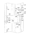
図1は、本発明の実施形態の一例に係る産業機械の旋回装置の構成例を示す縦断面図、図2は、図1の右側面図、図3は、図1の矢示III−III線に沿う断面図である。なお、便宜上、図1は、第1ストッパ部材と第2ストッパ部材の双方を記載している。また、図2、図3も、旋回装置の他の構成要素との関係を分り易くするために、主要な構成要素を適宜重ねて描写してある。 1 is a longitudinal sectional view showing a configuration example of a turning device for an industrial machine according to an example of an embodiment of the present invention, FIG. 2 is a right side view of FIG. 1, and FIG. 3 is an arrow III-III in FIG. It is sectional drawing which follows a line. For convenience, FIG. 1 shows both the first stopper member and the second stopper member. Also, FIGS. 2 and 3 also depict the main components appropriately overlapped so that the relationship with the other components of the swivel device can be easily understood.
この実施形態に係る旋回装置10は、産業ロボット12(産業機械)の第1関節部分に組み込まれる。この旋回装置10は、後述する出力フランジ18に固定されたモータ(図示略)と、揺動内接噛合型の遊星歯車減速機20と、を備え、産業ロボット12のベース部材14に対して旋回部材であるアーム16を所定の範囲内でのみ旋回させる。
The turning device 10 according to this embodiment is incorporated in a first joint portion of an industrial robot 12 (industrial machine). The turning device 10 includes a motor (not shown) fixed to an
以下、該旋回装置10の動力伝達系の構成から説明してゆく。 Hereinafter, the configuration of the power transmission system of the turning device 10 will be described.
前記モータは、図示せぬモータ軸の回転を、遊星歯車減速機20の入力歯車22に入力可能である。入力歯車22は、スプライン24を介して入力軸26と連結されている。入力軸26には、伝動歯車28が歯切り形成されている。伝動歯車28は、センタ歯車30と噛合している。
The motor can input rotation of a motor shaft (not shown) to the
センタ歯車30は、遊星歯車減速機20の軸心O1(後述する内歯歯車32、あるいは出力フランジ18の軸心に同じ)位置に配置された内側筒体34にニードル36を介して回転自在に支持されている。センタ歯車30は、前記伝動歯車28と噛合すると同時に3個の偏心体軸歯車38A〜38C(図1では偏心体軸歯車38Aのみ図示)と噛合している。
The
3個の偏心体軸歯車38A〜38Cは、3本の偏心体軸40A〜40C(図1では偏心体軸40Aのみ図示)にそれぞれ一体的に歯切り形成されている。各偏心体軸40A〜40Cは、この実施形態では、遊星歯車減速機20の軸心O1からオフセットされた位置で周方向に等間隔に設けられており、2枚の外歯歯車41、42をそれぞれ軸方向に貫通する態様で配置されている。
The three eccentric
各偏心体軸40A〜40Cの偏心体軸歯車38A〜38Cの軸方向両側には、それぞれ偏心体43、44が一体的に形成されている。各偏心体43、44の外周には、偏心体軸受45、47を介して前記外歯歯車41、42がそれぞれ嵌合している。外歯歯車41、42の偏心位相差は180度である。
Eccentric bodies 43 and 44 are integrally formed on both sides in the axial direction of the eccentric
外歯歯車41、42は、それぞれ内歯歯車32に内接噛合している。この実施形態では、内歯歯車32は、円柱状の内歯ピン32Aと該内歯ピン32Aを回転自在に支持するピン溝32B1を備えた内歯歯車本体32Bとで構成されている。内歯歯車本体32Bは遊星歯車減速機20のケーシング46と一体化されている。内歯歯車32の歯数(内歯ピン32Aの数)は、外歯歯車41、42の歯数よりも僅かだけ(この実施形態では1だけ)多い。
The
外歯歯車41、42の軸方向両側には出力フランジ18およびキャリヤ体48が一対の主軸受(アンギュラローラ軸受51、53)を介してケーシング46に支持されている。出力フランジ18およびキャリヤ体48は、それぞれ中空部18S、48Sを有し、複数(この例では6本)のキャリヤピン54およびキャリヤボルト55(共に図2にのみ図示)によって連結・一体化されている。出力フランジ18およびキャリヤ体48は、それぞれの入力軸穴18L、48Lにおいて前記入力軸26を一対の玉軸受56、57を介して支持している。また、出力フランジ18およびキャリヤ体48は、それぞれの偏心体軸穴18K、48Kにおいて前記偏心体軸40A〜40Cを一対のアンギュラローラ軸受58、59を介して支持している。
The
なお、前記センタ歯車30を支持している前記内側筒体34は、出力フランジ18の中空部18Sと同径の中空部34Sを有し、出力フランジ18およびキャリヤ体48の段部18A、48Aに嵌め込まれることで、該出力フランジ18およびキャリヤ体48と一体回転可能に組み込まれている。また、キャリヤ体48の軸方向反外歯歯車側には、ボルト60を介してケーシングカバー61が取り付けられている。
The inner
ケーシングカバー60と内側筒体34との間にはオイルシール65、ケーシング46と出力フランジ18との間にはオイルシール62、出力フランジ18の入力軸穴18Lと入力軸26との間にはオイルシール63が、それぞれ設けられている。また、出力フランジ18と内側筒体34の間にはOリング64が介在されている。これらのオイルシール62、63および65やOリング64により、遊星歯車減速機20内の空間が密閉されている。
An
ここで、旋回装置10の旋回範囲を制限するための構成について詳細に説明する。 Here, the structure for restrict | limiting the turning range of the turning apparatus 10 is demonstrated in detail.
この実施形態に係る旋回装置10では、遊星歯車減速機20の出力フランジ18に設けられた第1ストッパ部材66が、産業ロボット12のベース部材14側(この実施形態ではケーシング46)に設けられた第2ストッパ部材68に当接することによって、結果として出力フランジ18に固定されたアーム(旋回部材)16の旋回が規制・制限される。なお、ベース部材14は、工場の土台(あるいは、基礎フレーム)19に、ボルト21により固定されている。
In the turning device 10 according to this embodiment, the
始めに、遊星歯車減速機20の出力フランジ18、アーム(旋回部材)16、および第1ストッパ部材66の周辺の構成から説明する。
First, the configuration around the
遊星歯車減速機20の出力フランジ18は、該遊星歯車減速機20のケーシング46の外周の最小径部46S(外径d1)よりも径方向外側にδ1だけ延長された外径d2の延長部18Eを有している(d2−d1=δ1)。この延長部18Eに、旋回装置10の第1ストッパ部材66が設けられる。
The
第1ストッパ部材66は、図1において軸と平行な断面で、図2の付記描写において後述する第1ボルト穴66Fのピッチ円を含む円周方向の断面で、図3において軸と直角の断面で、図4において図3の矢示IVの半径方向からケーシング46の外周を見た部分展開図で、それぞれ示されている。
The
この実施形態では、第1ストッパ部材66は、出力フランジ18の延長部18Eと同一の外径d2の外周面66A、該外周面66Aと同軸(平行)の内周面66B、後述する第2ストッパ部材68に当接する第1、第2当接面66C、66D、および取付面66Eを有している。第1、第2当接面66C、66Dは、出力フランジ18に組み付けられたときに軸と直角でかつ半径方向(放射方向)に延在している。また、第1ストッパ部材66には、軸と平行に第1ストッパボルト70がねじ込まれる2個の第1ボルト穴66Fが形成されている。
In this embodiment, the
この実施形態では、第1ストッパ部材66の取り付け部として、出力フランジ18の延長部18Eに、該第1ストッパ部材66の内周面66Bおよび取付面66Eを位置決めするための12個の第1〜第12凹部72A〜72Lが、円周方向において12箇所、均等の間隔で形成されている(図1、図2に第1凹部72A、図4に第1凹部72A、第12凹部72Lのみ図示)。第1〜第12凹部72A〜72Lには、それぞれ、第1ストッパ部材66の前記2個の第1ボルト穴66Fに対応する位置に2個のフランジボルト穴18Dが形成されている。なお、フランジボルト穴18Dには、ねじは切られていない。
In this embodiment, twelve first through first positions for positioning the inner
要するならば、この実施形態に係る出力フランジ18は、第1ストッパ部材66の取り付け部として、該出力フランジ18の円周方向の360/12=30(度)毎に12個設けられた第1〜第12凹部72A〜72Lと、第1ストッパ部材66を出力フランジ18に固定する第1ストッパボルト70を貫通させるための12対、計24個のフランジボルト穴18Dを備えている。フランジボルト穴18Dのピッチ円径はd5である。
In short, 12
なお、この実施形態では、第1ストッパ部材66が出力フランジ18に固定されたときの中心角は、α1である(図2、図3参照)。
In this embodiment, the central angle when the
第1ストッパ部材66を取り付けるには、先ず、出力フランジ18の延長部18Eの第1〜第12凹部72A〜72Lのいずれかの位置(この実施形態では、第1凹部72A)に位置決めする。その後、フランジボルト穴18Dを介して2個の第1ストッパボルト70を、該第1ストッパ部材66の第1ボルト穴66Fにねじ込む。これにより、第1ストッパ部材66は、出力フランジ18の延長部18E(の任意の位置)に固定される。
In order to attach the
出力フランジ18には、産業ロボット12のアーム(旋回部材)16がアームボルト76を介して固定されている。このため、出力フランジ18にはアーム16の心出しおよび位置決めを行うためのリング状の溝18F、およびアームボルト穴18Hが形成されており、アーム16には前記溝18Fに係合する突部16Aが形成されている。
An arm (swivel member) 16 of the industrial robot 12 is fixed to the
第1ストッパ部材66を出力フランジ18に固定するための前記フランジボルト穴18Dは、アーム16を出力フランジ18に固定するためのアームボルト穴18Hよりも径方向外側に設けられ、また、第1ストッパボルト70は、アーム16の外周16B(外径d3)よりも更に径方向外側に位置している。これにより、アーム16を出力フランジ18から取り外すことなく、第1ストッパ部材66を取り付けたり、あるいは位置を変えたりすることができる。
The
次に減速機のケーシング46、ベース部材14、および第2ストッパ部材68の周辺の構成を説明する。
Next, the configuration around the
先ず、図1の紙面下側に着目して、減速機のケーシング46は、該ケーシング46の径方向外側に突出するリング状の突出部46Aを備えている。突出部46Aは、軸と直角の一対の第1、第2平行面46B、46Cを有し、ベース部材14を固定するベースボルト78を貫通させるための(ねじなしの)ボルト穴46Hを有している。ベースボルト78(ボルト穴46H)のピッチ円径は、前記フランジボルト穴18Dのピッチ円径と同一のd5である。
First, paying attention to the lower side of the drawing sheet of FIG. The
これに対し、産業用ロボット12のベース部材14は、リング板状の基部14Aに中空の円筒部14Bが連続した形状とされ、この円筒部14Bの軸方向端面14B1に、ベースボルト78がねじ込まれるベースボルト穴14Dを有している。
On the other hand, the
ベース部材14の円筒部14Bの軸方向端面14B1は、前記ケーシング46の(突出部46Aよりベース部材側の)外周46Mと、該突出部46Aのベース部材14側の第1平行面46Bとによって位置決めされている。ベース部材14は、この位置決め状態で、ベースボルト78を介して、遊星歯車減速機20のケーシング46に固定されている。
The axial end surface 14B1 of the
一方、図1の紙面上側を参照して、ケーシング46の突出部46Aの反ベース部材側の第2平行面46Cには、第1〜第12凹部82A〜82Lが、円周方向に等間隔に12個形成されている(図3参照。図1には第1凹部82Aのみ図示。図4に第1凹部82A、第2凹部82Bおよび第12凹部82Lの3個のみ図示)。本実施形態では、このうちの第1凹部82Aに第2ストッパ部材68が設けられている例が示されている。
On the other hand, referring to the upper side of FIG. 1, the first to twelfth recesses 82 </ b> A to 82 </ b> L are equally spaced in the circumferential direction on the second
また、該第1〜第12凹部82A〜82L内には、第2ストッパ部材68をケーシング46に固定する第2ストッパボルト86をねじ込むためのケーシングボルト穴46Eが、各2個(円周全体で12対、計24個)形成されている。
Further, in each of the first to
ケーシングボルト穴46Eのピッチ円径d5は、前記ベースボルト78(ボルト穴46H)のピッチ円径と同一であり、さらに、前述したように、このピッチ円径は、前記フランジボルト穴18Dのピッチ円径とも同一である(全てd5)。
The pitch circle diameter d5 of the
第2ストッパ部材68は、図1において軸と平行な断面で、図3において軸と直角の断面で、図4において図3の矢示IVの半径方向からケーシング46の外周を見た部分展開図で、それぞれ示されている。
The
この実施形態では、第2ストッパ部材68は、ケーシング46の突出部46Aと同一の外径d4の外周面68A、該外周面68Aと同軸(平行)の内周面68B、前記第1ストッパ部材66の第1、第2当接面66C、66Dの当接を受ける第1、第2受け面68C、68D、および取付面68Eを有している。
In this embodiment, the
第1、第2受け面68C、68Dは、ケーシング46に組み付けられたときに軸と直角でかつ半径方向(放射方向)に延在している。また、第2ストッパ部材68には、軸平行に2個の第2ボルト孔68Fが形成されている。なお、この第2ボルト孔68Fには、ねじは切られていない。
The first and second receiving surfaces 68 </ b> C and 68 </ b> D extend in the radial direction (radial direction) at right angles to the axis when assembled to the
第2ストッパ部材68は、ケーシング46の突出部46Aの第1〜第12凹部82A〜82Lのいずれかの位置(この実施形態では、第1凹部82A)に位置決めした状態で、第2ボルト孔68Fを介して2個の第2ストッパボルト86を、該ケーシング46の突出部46Aのケーシングボルト穴46Eにねじ込むことによって、ケーシング46の突出部46A(の任意の位置)に固定される。なお、この実施形態では、第2ストッパ部材68がケーシング46に固定されたときの中心角は、β1である。
The
結局、ベース部材14および第2ストッパ部材68は、ケーシング46の突出部46Aを挟んでケーシング46に対して固定されていることになる。これにより、遊星歯車減速機20のケーシング46をベース部材14に据え付けたまま、第2ストッパボルト86のみを締め付けるだけで該第2ストッパ部材68を取り付けることができる。
Eventually, the
図4に示されるように、第1ストッパ部材66の第1当接面66Cと第2ストッパ部材68の第1受け面68Cは、その一部が円周方向からみてδ2だけ重なっている。また、出力フランジ18(および該出力フランジ18と連結された産業ロボット12のアーム16)が矢印B方向に回転してほぼ一周すると、第1ストッパ部材66の第2当接面66Dと第2ストッパ部材68の第2受け面68Dが円周方向からみてやはりδ2だけ重なるようになる。
As shown in FIG. 4, the
次に、この旋回装置10の作用を説明する。 Next, the operation of the turning device 10 will be described.
モータの回転を受けて入力歯車22が回転すると、スプライン24を介して入力軸26が回転する。入力軸26の回転は、伝動歯車28を介してセンタ歯車30に伝達される。センタ歯車30が回転すると、該センタ歯車30と噛合している3個の偏心体軸歯車38A〜38Cが回転し、3本の偏心体軸40A〜40Cが同時にかつ同方向に回転する。この結果、各偏心体軸40A〜40Cに設けられた偏心体43、44がそれぞれ同期して回転し、各偏心体43、44の外周に偏心体軸受45、47を介して嵌合している外歯歯車41、42が互いに180度の偏心位相差を維持しつつ揺動しながら内歯歯車32に内接噛合する。
When the
この実施形態では、ケーシング46が旋回装置10のベース部材14に固定されているため、各偏心体軸40A〜40Cの偏心体43、44が1回回転すると(外歯歯車41、42が1回揺動すると)、外歯歯車41、42は内歯歯車32に対して歯数差に相当する「1歯」分だけ位相がずれる(自転する)。この外歯歯車41、42の自転成分が、各偏心体軸40A〜40Cの遊星歯車減速機20の軸心O1まわりの公転として出力フランジ18から取り出される。この結果、出力フランジ18とアームボルト76を介して連結されている旋回装置10のアーム(旋回部材)16が旋回する。
In this embodiment, since the
ここで、今、出力フランジ18が図4の矢印A方向に回転して図4の位置に到達すると、出力フランジ18に固定された第1ストッパ部材66の第1当接面66Cが、ケーシング46に固定された第2ストッパ部材68の第1受け面68Cに(重なりδ2の部分で)当接するようになる。この結果、出力フランジ18がケーシング46に対してこれ以上回転することができなくなる。
Here, when the
遊星歯車減速機20の出力フランジ18は、旋回装置10のアーム(旋回部材)16に固定されており、遊星歯車減速機20のケーシング46は、旋回装置10のベース部材14に固定されている。このため、結局、旋回装置10のベース部材14に対するアーム16の矢印A方向の旋回が規制(制限)される。
The
一方、出力フランジ18は、この状態でも、図4の矢印B方向には回転(逆転)可能である。しかし、出力フランジ18が図4の位置から矢印B方向に回転すると、やがて、該出力フランジ18に固定された第1ストッパ部材66が図4の想像線の位置に到達し、第1ストッパ部材66の第2当接面66Dが第2ストッパ部材68の第2受け面68Dに(重なりδ2の部分で)当接するようになる。これにより、全く同様に、旋回装置10のベース部材14に対するアーム16の矢印B方向のこれ以上の旋回が規制(制限)される。
On the other hand, even in this state, the
以上の作用により、この実施形態では、結局、旋回装置10のアーム16は、ケーシング46の第1凹部82Aを基点として、ベース部材14に対して、360−(α1+β1)度の範囲のみ旋回が許容されることになる。
As a result, in this embodiment, the arm 16 of the turning device 10 is allowed to turn only in the range of 360- (α1 + β1) degrees with respect to the
ベース部材14に対するアーム16の旋回の範囲を変更したいときは、出力フランジ18に設けられる第1ストッパ部材66の固定位置を変更すればよい。なお、第1、第2ストッパ部材の中心角α1、β1の大きさを変更しても、旋回範囲を変更することができる。
When it is desired to change the turning range of the arm 16 relative to the
また、第1ストッパ部材66を出力フランジ18に2個設けるようにした場合には、380−(α1+β1)度よりも小さな角度でのみ旋回を許容する旋回装置10とすることができる。例えば、第1ストッパ部材66を第1凹部72Aと120度離れた位置の第4凹部72D(図示はされていない)の2箇所に固定した場合には、出力フランジ18(すなわち該出力フランジ18に固定されたアーム16)を120−(α1+β1)度の範囲、或いは240−(α1+β1)の範囲でのみ旋回を許容する旋回装置10とすることができる。
Further, when two
なお、旋回範囲の変更は、ケーシング46に固定される第2ストッパ部材68の固定位置を、変更することによっても相対的にベース部材14に対するアーム16の旋回範囲を変更することができる。すなわち、今、第2ストッパ部材68が固定されている第1凹部82Aからそれ以外の第2〜第12凹部82B〜82Lのいずれかに変更することによってもアーム16の旋回範囲を変更できる。
Note that the turning range can be changed relative to the
また、360−(α1+β1)度よりも狭い範囲のみ旋回が許容される状態についても、1個の第1ストッパ部材66に対して第2ストッパ部材68を2個配置することによっても、先の第1ストッパ部材66を2個設ける場合と同様にして実現することができる。
Further, even in a state in which turning is allowed only in a range narrower than 360− (α1 + β1) degrees, it is also possible to arrange the
この実施形態においては、第1ストッパ部材66が(旋回装置10のアーム16にではなく)遊星歯車減速機20の出力フランジ18に固定されているため、極めて簡易な構成で自由度の高い制限機構を構築することができる。
In this embodiment, since the
また、本実施形態においては、出力フランジ18が、遊星歯車減速機20のケーシング46の最小外径部46Sよりも径方向を外側に延長された延長部18Eを有し、該延長部18Eに前記第1ストッパ部材66が設けられているため、第1ストッパ部材66を出力フランジ18の周方向のいずれの位置に取り付けても、出力フランジ18が旋回した際に第1ストッパ部材66が遊星歯車減速機20のケーシング46と干渉することがない。
Further, in the present embodiment, the
また、上記実施形態においては、第1ストッパ部材66を前記出力フランジ18に固定する第1ストッパボルト70をねじ込むためのフランジボルト穴18Dを、アーム16を該出力フランジ18に固定するアームボルト76をねじ込むためのアームボルト穴18Hよりも径方向外側に設けるようにしたため、アーム16を出力フランジ18に取り付けた状態のまま、第1ストッパ部材66の取り付け、位置換えが可能である。
In the above embodiment, the
また、上記実施形態では、ケーシング46が径方向外側に突出した突出部46Aを有し、ベース部材14および第2ストッパ部材68を、該突出部46Aを挟んで前記ケーシング46に対して固定するようにしたため、遊星歯車減速機20のケーシング、ひいては該遊星歯車減速機20の出力フランジ18に固定されている旋回装置10のアーム16の全体をベース部材14に据え付けたまま、第2ストッパ部材68を取り付けることができる。また、第2ストッパ部材68の位置の変更も容易である。
In the above embodiment, the
また、出力フランジ18に第1ストッパ部材66の取り付け部が複数設けられ、いずれかの取り付け部に第1ストッパ部材66が取り付けられる構成を採用したため、第1ストッパ部材66の位置の変更が、容易であり、かつ再現性が高い。第2ストッパ部材68についても同様の作用効果が得られている。
In addition, since the
また、第1、第2ストッパ部材66、68の取り付け部が、いずれも第1〜第12凹部72A〜72L、82A〜82Lと、第1、第2ストッパボルト70、86をねじ込むためのボルト穴18D、46Eと、を備える構成とされているため、簡易な構成で第1、第2ストッパ部材66、68の位置決めと固定が実現できる。
Further, the mounting portions of the first and
本実施形態の場合、第1ストッパ部材66のみならず、第2ストッパ部材68も(旋回装置10のベース部材14にではなく)減速機のケーシング46に固定されているため、旋回装置10の旋回範囲の設定・変更を、「遊星歯車減速機20のみ」で行うことができるため(旋回装置10のメインの構成要素であるベース部材14とアーム16には一切手を加える必要がないため)、設計の自由度およびを格段に向上させることができる。
In the case of the present embodiment, not only the
図5(A)〜(C)に上記実施形態の変形例を示す。 5A to 5C show a modification of the above embodiment.
上記実施形態においては、第2ストッパボルト86とベースボルト78は、別々に使用されていたが、この図5の変形例では、これを共通化し(兼用し)、第2ストッパ部材168が取り付けられる部分については、第2ストッパ部材168、ケーシング146(の突出部146A)、およびベース部材114を同一の共締めボルト179によって共締めするようにしている。
In the above embodiment, the
具体的には、この変形例においては、第2ストッパ部材168を位置決めする第1〜第12凹部182A〜182Lの周方向の範囲を、先の実施形態の第1〜第12凹部82A〜82Lの周方向の範囲より若干狭めている。また、第2ストッパ部材168の周方向長さを先の実施形態の第2ストッパ部材68の周方向長さよりも大きくするとともに(中心角β2を大きくするとともに)、周方向中央に第1〜第12凹部182A〜182Lに係合する突部168Tを有する形状としている。
Specifically, in this modification, the circumferential range of the first to
その上で、1個の第2ストッパ部材168を、先の実施形態の2つのベースボルト78相当部に跨がって2本の共締めボルト179によって取り付けている。結局、この共締めボルト179は、先の実施形態における第2ストッパ部材68を取り付ける第2ストッパボルト86と、ベース部材14とケーシング46とを連結するベースボルト78の機能を兼用したものとなっている。また、第2ストッパ部材168の中心角β2が、先の実施形態の第2ストッパ部材68の中心角β1より大とされ、アーム116(図5では図示略)の旋回範囲を若干狭めている。この変形例によれば、共締めボルト179を使用した分、部品点数の削減ができ、また、先の実施形態では必要とされた第2ストッパ部材68を取り付けるためだけに用いるケーシングボルト穴(46E)の穴開けが不要となるため、製造の簡素化も図れる。
In addition, one
その他の構成は、先の実施形態と同様であるため、図5中で先の実施形態と同一または機能的に類似する部位に、下2桁が先の実施形態と同一の符号を付し、重複説明を省略する。 Since the other configuration is the same as that of the previous embodiment, the lower two digits are attached with the same reference numerals as those of the previous embodiment in the same or functionally similar parts as those of the previous embodiment in FIG. Duplicate explanation is omitted.
次に、図6〜図9を用いて本発明の他の実施形態の一例について説明する。 Next, an example of another embodiment of the present invention will be described with reference to FIGS.
この実施形態においては、動力伝達系の構成、および第2ストッパ部材268の被取り付け部材が、先の実施形態と異なっている。
In this embodiment, the configuration of the power transmission system and the attached member of the
先ず、この実施形態に係る旋回装置210の動力伝達系の構成について簡単に説明する。
First, the configuration of the power transmission system of the
モータ204のモータ軸206の先端にはピニオン208が形成されている。ピニオン208は歯車223と噛合している。歯車223は、スプライン239を介して偏心体軸240Aに連結されている。偏心体軸240Aには、偏心体243、244が設けられている。偏心体243、244には、偏心体軸受245、247を介して外歯歯車241、242が外嵌されている。
A
この実施形態では、外歯歯車241、242の揺動は、この1本の偏心体軸240Aに設けられた偏心体243、244によって行われる。すなわち、(この実施形態では偏心体軸240A〜240Cは計3本存在しているが)他の2本の偏心体軸240B、240C(図6では、このうちの偏心体軸240Aのみ図示)は、単に外歯歯車241、242の揺動を支持しているだけで、駆動力は与えていない。すなわち、他の2本の偏心体軸240B、240Cは、従動用の偏心体軸である。そのため、当該他の2本の偏心体軸240B、240Cは、その外径や偏心体243s、244sの外径、偏心体軸受245s、247sの外径等が、駆動用の偏心体軸240Aより小さく設定されている。但し、偏心体243、243s、244、244sの偏心量は全ての偏心体軸240A〜240Cで同一である。
In this embodiment, the
この構成に係る偏心揺動型の遊星歯車減速機220は、センタ歯車(30)や偏心体軸歯車(38A〜38C)等が不要であり、構成が簡易かつ低コストである。しかし、外歯歯車241、242および内歯歯車223による減速のメカニズムに関しては、基本的に先の実施形態と同様の作用が得られる。
The eccentric oscillating planetary gear speed reducer 220 according to this configuration does not require a center gear (30), eccentric body shaft gears (38A to 38C), etc., and has a simple configuration and low cost. However, regarding the mechanism of deceleration by the
この実施形態においても、産業ロボット212のベース部材214が遊星歯車減速機220のケーシング246に固定され、アーム216(旋回部材)が該遊星歯車減速機220の出力フランジ218に固定されることで、先の実施形態と同様に、アーム216をベース部材214に対して旋回させることができる。
Also in this embodiment, the
すなわち、この旋回装置210の出力フランジ218も、先の実施形態と同様に、ケーシング246の最小外径部246Sよりも径方向外側にδ201だけ延長された延長部218Eを有し、該延長部218Eに第1ストッパ部材266が設けられている。第1ストッパ部材266自体およびその周辺の構造は、先の実施形態と同様であり、産業ロボット212のアーム216を組み付けた状態のまま(分解することなく)第1ストッパ部材266の取り付け取り外しが可能である点も、先の実施形態と同様に得られている。
That is, the
しかしながら、第2ストッパ部材268は、この実施形態では、遊星歯車減速機220のケーシング246にではなく、旋回装置210のベース部材214が固定されている(ベース部材214側の)土台219に、該ベース部材214と隣接してボルト215によって直接取り付けられている。
However, in this embodiment, the
この第2ストッパ部材268は、土台219上に載置される据え付け部268Xと、該据え付け部268Xから立設された柱部268Yと、該柱部268Yの上部から反据え付け部268X側に延在された受け部268Zとから主に構成されている。そして、受け部268Zに、第1ストッパ部材266の第1、第2当接面266C、266Dが当接する第1、第2受け面268C、268Dが備えられている。符号268V、268Wは、補強部材である。各部は、溶接または金属用接着剤にて固着されている。
The
図6〜図9の各図では、第1ストッパ部材266の第1当接面268Cが第2ストッパ部材268の第1受け面268Cに当接し、出力フランジ218(および該出力フランジ218に連結されたアーム216)が矢印A方向に回転するのが規制されている状態を示している。
6-9, the
この構成によっても、旋回装置210のアーム216をベース部材214に対して任意の角度だけ旋回可能とする作用効果を先の実施形態と同様に得ることができる。特に、この実施形態にあっては、第2ストッパ部材268が、ベース部材214が据えつけられている土台219に直接設けられているため、該第2ストッパ部材268の取り付け位置を、遊星歯車減速機220のケーシング246、或は出力フランジ218に対して円周方向の任意の位置にアナログ的に微調整して設けることができる。そのため、アーム216の旋回範囲を(先の実施形態のように30度ごとの角度ではなく)全く任意の角度に設定することが可能である。このように、本発明においては、第2ストッパ部材268については、必ずしも遊星歯車減速機220のケーシング246に設ける必要はない。
Also with this configuration, the effect of enabling the
なお、本発明は、旋回装置の旋回範囲を規制することができる発明であるが、本発明の構成を利用することによって、例えば点検時において、一時的にベース部材に対して旋回部材が意図せぬ旋回をしないように、固定するための手段としても活用することができる。 The present invention is an invention that can regulate the swivel range of the swivel device. However, by using the configuration of the present invention, for example, during inspection, the swivel member is temporarily intended with respect to the base member. It can also be used as a means for fixing so as not to turn.
この活用例を図10に示す。 An example of this utilization is shown in FIG.
すなわち、この実施形態では、基本構造自体は先の図1〜図4の構成と同様の構成を有している。すなわち、第1ストッパ部材66を位置決めするための第1〜第12凹部72A〜72Lが、出力フランジ18に形成されている。また、第2ストッパ部材68を位置決めするための第1〜第12凹部82A〜82Lが、ケーシング46に形成されている。そして、第3ストッパ部材95が、第1ストッパ部材66用の第1〜第12凹部72A〜72Lと第2ストッパ部材68用の第1〜第12凹部82A〜82Lの双方に係合した上で、第1ストッパボルト70(図10では図示略)によって出力フランジ18に固定されている。なお、第3ストッパ部材95の固定は、ケーシング46側で行ってもよく、一時的ならば、ボルト止めはしなくてもよい。各部の具体的な構成は、既に説明した第1、第2ストッパ部材66、68およびその周辺の構成と同様である。
That is, in this embodiment, the basic structure itself has the same configuration as the configuration shown in FIGS. That is, first to twelfth recesses 72 </ b> A to 72 </ b> L for positioning the
点検時の旋回部材の物理的な固定は、安全上、必要であるが、従来は、必ずしも簡単には実現できず、準備等に多大な時間とコストを要することがあった。上記構成を採用することにより、アーム16(旋回部材)をベース部材14に対して完全に止めることが容易にできる。別の見方をするならば、簡単に旋回可能範囲を「零」とすることができる。
The physical fixing of the swivel member at the time of inspection is necessary for safety. However, conventionally, the swivel member cannot always be easily realized, and it may take a lot of time and cost for preparation. By adopting the above configuration, the arm 16 (swivel member) can be easily stopped completely with respect to the
なお、本発明は、ベース部材に対する旋回部材の旋回範囲を、物理的に制限するものであるが、実際の旋回制御においては、必ずしもメインの制御ルーチンで本発明の旋回規制を直接利用する必要はない。例えば、(メインの制御ルーチンでは、例えばモータのエンコーダの検出値等を利用して旋回範囲を規制するが)メインの制御ルーチンに何らかの不具合が生じたときの旋回部材の暴走を防止するフェイルセーフ用として本発明を適用してもよい。また、第1、第2ストッパ部材の実際の当接あるいは当接の直前を検知するタッチセンサや磁気センサ等を本発明の第1、第2ストッパ部材の当接面と受け面の間に組み込み、これらのセンサの信号にて、第1、第2ストッパ部材の当接を検知して旋回範囲を規制するものであってもよい。この場合であっても、(センサに不具合があったとしても)本発明の旋回制限がフェイルセーフ用として有効に機能する。 Although the present invention physically limits the swivel range of the swivel member relative to the base member, in actual swivel control, it is not always necessary to directly use the swivel control of the present invention in the main control routine. Absent. For example, in the main control routine, the turning range is regulated using, for example, the detection value of the encoder of the motor, etc., for fail-safe to prevent runaway of the turning member when some trouble occurs in the main control routine The present invention may be applied as follows. In addition, a touch sensor, a magnetic sensor, or the like that detects actual contact of the first and second stopper members or just before contact is incorporated between the contact surface and the receiving surface of the first and second stopper members of the present invention. The contact range of the first and second stopper members may be detected by signals from these sensors to restrict the turning range. Even in this case, even if the sensor is defective, the turning limitation of the present invention functions effectively for fail-safe use.
なお、上記実施形態においては、減速機として、いずれも偏心揺動型の減速機構を有する遊星歯車減速機が採用されていたが、本発明に係る旋回装置に適用される減速機は、このような減速機に限定されるものではなく、例えば、単純遊星歯車機構を備えた減速機や、平行軸減速機構や直交減速機構を備えた減速機、あるいはこれらを組み合わせた減速機構を備えた減速機であってもよい。 In the above embodiment, the planetary gear speed reducer having an eccentric oscillating speed reduction mechanism is employed as the speed reducer. However, the speed reducer applied to the turning device according to the present invention is as described above. For example, a speed reducer with a simple planetary gear mechanism, a speed reducer with a parallel shaft speed reduction mechanism or an orthogonal speed reduction mechanism, or a speed reducer with a combination of these speed reducers It may be.
また、上記実施形態においては、前記出力フランジが、減速機のケーシングの最小外径部よりも径方向外側に延長された延長部を有し、該延長部に前記第1ストッパ部材が設けられていたが、例えば旋回範囲が比較的限定されていてケーシングとの干渉が問題とならないような場合には、必ずしもこのような構成とされている必要はない。 Moreover, in the said embodiment, the said output flange has the extension part extended in the radial direction outer side than the minimum outer diameter part of the casing of a reduction gear, The said 1st stopper member is provided in this extension part. However, for example, when the turning range is relatively limited and interference with the casing does not cause a problem, such a configuration is not necessarily required.
また、上記第1の実施形態においては、ケーシングが径方向外側に突出した突出部を有し、ベース部材および第2ストッパ部材が、該突出部を挟んで前記ケーシングに対して固定されている構成を採用していた。しかし、本発明においては、第2ストッパ部材とケーシングの取り付けと、ベース部材とケーシングの取り付けは、特に関連させる必要はなく、例えば、第2ストッパ部材を(ケーシングにではなく)ベース部材自体に取り付けてもよく、あるいは、上記第2の実施形態のように、該ベース部材の据え付けられている土台(床材やベースフレーム等:ベース部材側)に直接取り付けてもよい。 Moreover, in the said 1st Embodiment, the casing has the protrusion part which protruded to radial direction outer side, and the base member and the 2nd stopper member are being fixed with respect to the said casing on both sides of this protrusion part Was adopted. However, in the present invention, the attachment of the second stopper member and the casing and the attachment of the base member and the casing need not be particularly related. For example, the second stopper member is attached to the base member itself (not to the casing). Alternatively, as in the second embodiment, the base member may be directly attached to a base (floor material, base frame, etc .: base member side) on which the base member is installed.
また、上記実施形態においては、出力フランジに第1、第2ストッパ部材の取り付け部が複数設けられ、いずれかの取り付け部に第1、第2ストッパ部材が取り付けられる構成を採用していたが、例えば上記第2の実施形態のように、このような取り付け部を1個(1箇所)のみとしてもよい。 In the above embodiment, the output flange is provided with a plurality of first and second stopper member attachment portions, and the first and second stopper members are attached to any of the attachment portions. For example, as in the second embodiment, only one (one place) may be provided for such an attachment portion.
また、第1ストッパ部材(あるいは第2ストッパ部材)の取り付け部の構成も、要は、第1ストッパ部材(あるいは第2ストッパ部材)の適切な位置決めと固定がなされる構成であれば良く、上記構成例に限定されるものではない。 In addition, the configuration of the mounting portion of the first stopper member (or the second stopper member) may be any configuration as long as the first stopper member (or the second stopper member) is appropriately positioned and fixed. It is not limited to the configuration example.
また、上記実施形態においては、第1ストッパ部材を前記出力フランジに固定するボルトをねじ込むためのボルト孔を、前記旋回部材を該出力フランジに固定するボルトをねじ込むためのボルト孔よりも径方向外側に設け、これにより、旋回部材を出力フランジに取り付けた状態のまま、第1ストッパ部材の取り付け、位置換えを可能としていたが、本発明においては、必ずしもこのような構成とされている必要もない。 Moreover, in the said embodiment, the bolt hole for screwing the volt | bolt which fixes a 1st stopper member to the said output flange is radially outer than the bolt hole for screwing the volt | bolt which fixes the said turning member to this output flange. Thus, the first stopper member can be mounted and repositioned while the swivel member is mounted on the output flange. However, in the present invention, such a configuration is not necessarily required. .
更に、上記実施形態においては、点検時等において旋回部材を完全固定するための第3ストッパの装着を可能とする構成が開示されていたが、本発明においては、当該第3ストッパについては、必ずしも装着可能な構成となっている必要はない。 Furthermore, in the above-described embodiment, a configuration that enables the mounting of the third stopper for completely fixing the turning member at the time of inspection or the like has been disclosed. However, in the present invention, It is not necessary to be able to install.
10…旋回装置
12…産業ロボット
14…ベース部材
16…アーム
18…出力フランジ
20…遊星歯車減速機
22…入力歯車
32…内歯歯車
46…ケーシング
46A…突出部
48…キャリヤ体
66…第1ストッパ部材
68…第2ストッパ部材
DESCRIPTION OF SYMBOLS 10 ... Turning apparatus 12 ...
Claims (7)
前記減速機は、ケーシングおよび出力フランジを備え、
前記ベース部材が前記減速機のケーシングに固定されるとともに、
前記旋回部材が前記減速機の出力フランジに固定され、かつ
前記減速機の出力フランジに設けられた第1ストッパ部材と、
前記ベース部材側に設けられ、前記減速機の前記第1ストッパ部材が当接することにより前記旋回部材の旋回を制限する第2ストッパ部材と、を備え、
前記出力フランジは、前記減速機のケーシングの最小外径部よりも径方向外側に延長された延長部を有し、
該延長部に前記第1ストッパ部材が設けられる
ことを特徴とする産業機械の旋回装置。 In a turning device for an industrial machine having a base member and a turning member that turns with respect to the base member via a speed reducer,
The speed reducer includes a casing and an output flange,
The base member is fixed to a casing of the speed reducer;
A first stopper member fixed to an output flange of the speed reducer, and a first stopper member provided on the output flange of the speed reducer;
A second stopper member that is provided on the base member side and restricts the turning of the turning member by contacting the first stopper member of the speed reducer ;
The output flange has an extended portion extending radially outward from a minimum outer diameter portion of the casing of the speed reducer;
A swiveling device for an industrial machine , wherein the extension portion is provided with the first stopper member .
前記減速機は、ケーシングおよび出力フランジを備え、
前記ベース部材が前記減速機のケーシングに固定されるとともに、
前記旋回部材が前記減速機の出力フランジに固定され、かつ
前記減速機の出力フランジに設けられた第1ストッパ部材と、
前記ベース部材側に設けられ、前記減速機の前記第1ストッパ部材が当接することにより前記旋回部材の旋回を制限する第2ストッパ部材と、を備え、
前記第2ストッパ部材がケーシングに設けられ、
前記第2ストッパ部材の取り付けボルトが、前記ケーシングを前記ベース部材に取り付けるボルトと兼用されている
ことを特徴とする産業機械の旋回装置。 In a turning device for an industrial machine having a base member and a turning member that turns with respect to the base member via a speed reducer,
The speed reducer includes a casing and an output flange,
The base member is fixed to a casing of the speed reducer;
The swivel member is fixed to an output flange of the speed reducer; and
A first stopper member provided on an output flange of the speed reducer;
A second stopper member that is provided on the base member side and restricts the turning of the turning member by contacting the first stopper member of the speed reducer;
The second stopper member is provided on the casing ;
An industrial machine turning device characterized in that a mounting bolt of the second stopper member is also used as a bolt for mounting the casing to the base member .
前記減速機は、ケーシングおよび出力フランジを備え、
前記ベース部材が前記減速機のケーシングに固定されるとともに、
前記旋回部材が前記減速機の出力フランジに固定され、かつ
前記減速機の出力フランジに設けられた第1ストッパ部材と、
前記ベース部材側に設けられ、前記減速機の前記第1ストッパ部材が当接することにより前記旋回部材の旋回を制限する第2ストッパ部材と、を備え、
前記第2ストッパ部材がケーシングに設けられ、
前記ケーシングが径方向外側に突出した突出部を有し、
前記ベース部材および前記第2ストッパ部材が、該突出部を挟んで前記ケーシングに対して固定されている
ことを特徴とする産業機械の旋回装置。 In a turning device for an industrial machine having a base member and a turning member that turns with respect to the base member via a speed reducer,
The speed reducer includes a casing and an output flange,
The base member is fixed to a casing of the speed reducer;
The swivel member is fixed to an output flange of the speed reducer; and
A first stopper member provided on an output flange of the speed reducer;
A second stopper member that is provided on the base member side and restricts the turning of the turning member by contacting the first stopper member of the speed reducer;
The second stopper member is provided on the casing;
The casing has a protruding portion protruding radially outward;
The base member and the second stopper member are fixed to the casing with the projecting portion interposed therebetween.
前記減速機は、ケーシングおよび出力フランジを備え、
前記ベース部材が前記減速機のケーシングに固定されるとともに、
前記旋回部材が前記減速機の出力フランジに固定され、かつ
前記減速機の出力フランジに設けられた第1ストッパ部材と、
前記ベース部材側に設けられ、前記減速機の前記第1ストッパ部材が当接することにより前記旋回部材の旋回を制限する第2ストッパ部材と、を備え、
前記第1ストッパ部材を前記出力フランジに固定するボルトのボルト孔を、前記旋回部材を該出力フランジに固定するボルトのボルト孔よりも径方向外側に設けた
ことを特徴とする産業機械の旋回装置。 In a turning device for an industrial machine having a base member and a turning member that turns with respect to the base member via a speed reducer,
The speed reducer includes a casing and an output flange,
The base member is fixed to a casing of the speed reducer;
The swivel member is fixed to an output flange of the speed reducer; and
A first stopper member provided on an output flange of the speed reducer;
A second stopper member that is provided on the base member side and restricts the turning of the turning member by contacting the first stopper member of the speed reducer;
A swivel device for an industrial machine, wherein a bolt hole for a bolt for fixing the first stopper member to the output flange is provided radially outside a bolt hole for the bolt for fixing the swivel member to the output flange. .
前記減速機は、ケーシングおよび出力フランジを備え、
前記ベース部材が前記減速機のケーシングに固定されるとともに、
前記旋回部材が前記減速機の出力フランジに固定され、かつ
前記減速機の出力フランジに設けられた第1ストッパ部材と、
前記ベース部材側に設けられ、前記減速機の前記第1ストッパ部材が当接することにより前記旋回部材の旋回を制限する第2ストッパ部材と、を備え、
前記第1ストッパ部材を位置決めする第1ストッパ部材用の凹部が前記出力フランジに形成されるとともに、前記第2ストッパ部材を位置決めする第2ストッパ部材用の凹部が前記ケーシングに形成され、かつ、
前記第1ストッパ部材用の凹部と第2ストッパ部材用の凹部の双方に同時に係合する第3ストッパ部材を備えた
ことを特徴とする産業機械の旋回装置。 In a turning device for an industrial machine having a base member and a turning member that turns with respect to the base member via a speed reducer,
The speed reducer includes a casing and an output flange,
The base member is fixed to a casing of the speed reducer;
The swivel member is fixed to an output flange of the speed reducer; and
A first stopper member provided on an output flange of the speed reducer;
A second stopper member that is provided on the base member side and restricts the turning of the turning member by contacting the first stopper member of the speed reducer;
A recess for a first stopper member for positioning the first stopper member is formed in the output flange, and a recess for a second stopper member for positioning the second stopper member is formed in the casing; and
An industrial machine swivel device comprising a third stopper member that simultaneously engages both the first stopper member recess and the second stopper member recess.
前記出力フランジに前記第1ストッパ部材の取り付け部が複数設けられ、いずれかの取り付け部に前記第1ストッパ部材が取り付けられる
ことを特徴とする産業機械の旋回装置。 In any one of Claims 1-5,
A plurality of attachment portions of the first stopper member are provided on the output flange, and the first stopper member is attached to any of the attachment portions.
前記取り付け部が、第1ストッパ部材を位置決めする凹部と、該第1ストッパ部材を前記出力フランジに固定するボルトのボルト孔と、を備える
ことを特徴とする産業機械の旋回装置。 In claim 6,
The swivel device for an industrial machine, wherein the attachment portion includes a recess for positioning the first stopper member, and a bolt hole for a bolt for fixing the first stopper member to the output flange.
Priority Applications (1)
| Application Number | Priority Date | Filing Date | Title |
|---|---|---|---|
| JP2011194445A JP5709700B2 (en) | 2011-09-06 | 2011-09-06 | Industrial machinery swivel |
Applications Claiming Priority (1)
| Application Number | Priority Date | Filing Date | Title |
|---|---|---|---|
| JP2011194445A JP5709700B2 (en) | 2011-09-06 | 2011-09-06 | Industrial machinery swivel |
Publications (2)
| Publication Number | Publication Date |
|---|---|
| JP2013056376A JP2013056376A (en) | 2013-03-28 |
| JP5709700B2 true JP5709700B2 (en) | 2015-04-30 |
Family
ID=48132723
Family Applications (1)
| Application Number | Title | Priority Date | Filing Date |
|---|---|---|---|
| JP2011194445A Active JP5709700B2 (en) | 2011-09-06 | 2011-09-06 | Industrial machinery swivel |
Country Status (1)
| Country | Link |
|---|---|
| JP (1) | JP5709700B2 (en) |
Cited By (1)
| Publication number | Priority date | Publication date | Assignee | Title |
|---|---|---|---|---|
| JP2013139062A (en) * | 2011-12-28 | 2013-07-18 | Sumitomo Heavy Ind Ltd | Revolving device of industrial machine |
Families Citing this family (3)
| Publication number | Priority date | Publication date | Assignee | Title |
|---|---|---|---|---|
| JP2015163414A (en) * | 2014-02-28 | 2015-09-10 | ファナック株式会社 | Robot equipped with fastening device that regulate relative rotation movement of two member and fastening device |
| JP7260398B2 (en) | 2019-05-24 | 2023-04-18 | ファナック株式会社 | Arm fixing device |
| JP2022096111A (en) * | 2020-12-17 | 2022-06-29 | セイコーエプソン株式会社 | Robot arm and robot |
Family Cites Families (6)
| Publication number | Priority date | Publication date | Assignee | Title |
|---|---|---|---|---|
| JPS614683A (en) * | 1984-06-20 | 1986-01-10 | トキコ株式会社 | Industrial robot |
| JPH03239495A (en) * | 1990-02-15 | 1991-10-25 | Mitsubishi Electric Corp | Wrist unit structure in articulated robot |
| JPH0580692U (en) * | 1992-04-10 | 1993-11-02 | 株式会社不二越 | Swing axis control device for industrial robots |
| JP4131086B2 (en) * | 2001-02-16 | 2008-08-13 | 株式会社デンソー | Robot joint structure |
| JP3893302B2 (en) * | 2002-03-26 | 2007-03-14 | 住友重機械工業株式会社 | Reducer and geared motor |
| JP5406644B2 (en) * | 2009-09-14 | 2014-02-05 | ナブテスコ株式会社 | Swivel device |
-
2011
- 2011-09-06 JP JP2011194445A patent/JP5709700B2/en active Active
Cited By (1)
| Publication number | Priority date | Publication date | Assignee | Title |
|---|---|---|---|---|
| JP2013139062A (en) * | 2011-12-28 | 2013-07-18 | Sumitomo Heavy Ind Ltd | Revolving device of industrial machine |
Also Published As
| Publication number | Publication date |
|---|---|
| JP2013056376A (en) | 2013-03-28 |
Similar Documents
| Publication | Publication Date | Title |
|---|---|---|
| KR101258241B1 (en) | Hollow reduction gear | |
| JP5466741B2 (en) | Reduction gear | |
| JP5478893B2 (en) | Gear device | |
| US7070533B2 (en) | Internal teeth oscillation type inner gearing planetary gear system | |
| JP2007046730A (en) | Reduction gear device | |
| WO2006115257A1 (en) | Turning portion structure of industrial robot | |
| JP5709700B2 (en) | Industrial machinery swivel | |
| JP2010151196A (en) | Speed reducer | |
| WO2012073596A1 (en) | Gear transmission | |
| JPWO2009057526A1 (en) | Reduction gear | |
| JP5856478B2 (en) | Industrial machinery swivel | |
| JP6237205B2 (en) | Planetary gear mechanism | |
| JP5868826B2 (en) | Reduction gear | |
| JP4372063B2 (en) | Eccentric differential reducer | |
| JP5918704B2 (en) | Reduction gear | |
| JP2006283876A (en) | Rotary motion transmitting device | |
| JP4804439B2 (en) | Reducer | |
| JP4219320B2 (en) | Robot swivel structure | |
| JP2008025846A5 (en) | ||
| TW202027936A (en) | Rotating mechanism of industrial machine, speed reducer, industrial machine and driving device for improving degree of freedom of bolt configuration for fixing speed reducer to industrial machine | |
| JP2008014500A5 (en) | ||
| JP4999978B2 (en) | Eccentric differential reducer | |
| JP4845791B2 (en) | Eccentric oscillating gear mechanism | |
| JP4707499B2 (en) | Rotation drive mechanism | |
| JP2016211643A (en) | Speed reducer and manufacturing method of speed reducer |
Legal Events
| Date | Code | Title | Description |
|---|---|---|---|
| A621 | Written request for application examination |
Free format text: JAPANESE INTERMEDIATE CODE: A621 Effective date: 20131008 |
|
| A977 | Report on retrieval |
Free format text: JAPANESE INTERMEDIATE CODE: A971007 Effective date: 20140630 |
|
| A131 | Notification of reasons for refusal |
Free format text: JAPANESE INTERMEDIATE CODE: A131 Effective date: 20140708 |
|
| A521 | Written amendment |
Free format text: JAPANESE INTERMEDIATE CODE: A523 Effective date: 20140904 |
|
| TRDD | Decision of grant or rejection written | ||
| A01 | Written decision to grant a patent or to grant a registration (utility model) |
Free format text: JAPANESE INTERMEDIATE CODE: A01 Effective date: 20150224 |
|
| A61 | First payment of annual fees (during grant procedure) |
Free format text: JAPANESE INTERMEDIATE CODE: A61 Effective date: 20150303 |
|
| R150 | Certificate of patent or registration of utility model |
Ref document number: 5709700 Country of ref document: JP Free format text: JAPANESE INTERMEDIATE CODE: R150 |