JP4804439B2 - Reducer - Google Patents
Reducer Download PDFInfo
- Publication number
- JP4804439B2 JP4804439B2 JP2007259473A JP2007259473A JP4804439B2 JP 4804439 B2 JP4804439 B2 JP 4804439B2 JP 2007259473 A JP2007259473 A JP 2007259473A JP 2007259473 A JP2007259473 A JP 2007259473A JP 4804439 B2 JP4804439 B2 JP 4804439B2
- Authority
- JP
- Japan
- Prior art keywords
- gear
- external gear
- diameter
- external
- carrier
- Prior art date
- Legal status (The legal status is an assumption and is not a legal conclusion. Google has not performed a legal analysis and makes no representation as to the accuracy of the status listed.)
- Active
Links
- 239000003638 chemical reducing agent Substances 0.000 title claims description 24
- 230000005540 biological transmission Effects 0.000 description 6
- 230000007246 mechanism Effects 0.000 description 4
- 230000004323 axial length Effects 0.000 description 3
- 230000000149 penetrating effect Effects 0.000 description 3
- 230000010355 oscillation Effects 0.000 description 2
- 229910000897 Babbitt (metal) Inorganic materials 0.000 description 1
- 230000008878 coupling Effects 0.000 description 1
- 238000010168 coupling process Methods 0.000 description 1
- 238000005859 coupling reaction Methods 0.000 description 1
- 239000000428 dust Substances 0.000 description 1
Images


Landscapes
- Retarders (AREA)
Description
この発明は、外歯車からなる前段減速機と偏心揺動型減速機とを組み合わせた減速装置に関する。 The present invention relates to a speed reduction equipment that combines the pre-stage speed reducer composed of external gears eccentrically oscillating speed reducer.
従来の減速装置としては、例えば以下の特許文献1に記載されているようなものが知られている。
このものは、内歯が設けられた略円筒状のケース、内歯に噛み合う外歯が設けられたピニオン、第2外歯車が取り付けられるとともに、ピニオンに偏心部が挿入された複数本のクランク軸、ケースに相対回転可能に支持されるとともに、クランク軸を回転可能に支持するキャリアを有する偏心揺動型減速機と、モータの出力軸に設けられた第1外歯車と、第1外歯車に噛み合う大径歯車と、小径歯車と、第2外歯車より軸方向外側のクランク軸に支持され、前記大径、小径歯車が設けられた第4外歯車と、モータの出力軸に回転可能に支持され、前記小径歯車に噛み合う大歯車および第2外歯車に噛み合う小歯車が設けられた第3外歯車とを備えたものである。 This has a substantially cylindrical case with internal teeth, a pinion with external teeth meshing with the internal teeth, a plurality of crankshafts with a second external gear attached and an eccentric part inserted into the pinion An eccentric oscillating speed reducer having a carrier rotatably supported by the case and rotatably supporting the crankshaft, a first external gear provided on the output shaft of the motor, and a first external gear A meshed large-diameter gear, a small-diameter gear, and a fourth external gear supported by the crankshaft axially outside the second external gear and provided with the large-diameter and small-diameter gears, and rotatably supported by the output shaft of the motor And a third external gear provided with a large gear meshing with the small-diameter gear and a small gear meshing with the second external gear.
しかしながら、このような従来の減速装置にあっては、全てのクランク軸の軸方向片側端に3段の外歯車、即ち、第2外歯車、第4外歯車の大径歯車および小径歯車が同軸関係を保持しながら近接配置されているため、減速装置全体の軸方向長が長くなって大型化するという課題があった。さらに、大径歯車、小径歯車を有する歯車(第3、第4外歯車)を2種類使用しているため、構造が複雑となってしまうという課題もあった。 However, in such a conventional speed reducer, three stages of external gears, that is, the second external gear, the large external gear of the fourth external gear, and the small external gear are coaxially arranged at one axial end of all crankshafts. Since they are arranged close to each other while maintaining the relationship, there is a problem that the axial length of the entire reduction gear device becomes longer and the size thereof increases. Furthermore, since two types of gears (third and fourth external gears) having a large diameter gear and a small diameter gear are used, there is a problem that the structure becomes complicated.
この発明は、構造簡単で小型でありながら、エネルギーロスの少ない低騒音の減速装置を提供することを目的とする。 The present invention yet compact simple structure, and to provide less noise reduction equipment of the energy loss.
このような目的は、内歯が設けられた略円筒状のケース、内歯に噛み合う外歯が設けられたピニオン、第2外歯車が取り付けられるとともに、ピニオンに偏心部が挿入された複数本のクランク軸、ケースに相対回転可能に支持されるとともに、クランク軸を回転可能に支持するキャリアを有する偏心揺動型減速機と、モータの出力軸に設けられた第1外歯車と、第1外歯車からモータの回転が伝達される大径歯車と、大径歯車に伝達された回転を第2外歯車へと伝達する小径歯車と、キャリアに支持され、前記大径、小径歯車が設けられた支持軸とを備えた減速装置において、前記支持軸をクランク軸から周方向に離れた位置に配置することにより、達成することができる。 These objects, substantially cylindrical casing which has internal teeth provided, pinion external teeth is provided meshing with the internal teeth, the second external gear is mounted, a plurality of the eccentric portion is inserted into the pinion An eccentric oscillating speed reducer having a carrier that is rotatably supported by the crankshaft and the case and that rotatably supports the crankshaft, a first external gear provided on the output shaft of the motor, and a first outer gear A large-diameter gear that transmits the rotation of the motor from the gear, a small-diameter gear that transmits the rotation transmitted to the large-diameter gear to the second external gear, and the large-diameter and small-diameter gear supported by the carrier are provided. In a reduction gear including a support shaft, this can be achieved by arranging the support shaft at a position away from the crankshaft in the circumferential direction .
この発明においては、前述のようにキャリアに支持された支持軸には大径歯車、小径歯車が支持され、一方、クランク軸には第2外歯車が取り付けられているだけであるため、減速装置全体の軸方向長が短くなり、小型化が可能となり、さらに、構造を簡単なものとすることもできる。 In the present invention, since the large-diameter gear and the small-diameter gear are supported on the support shaft supported by the carrier as described above, while the second external gear is only attached to the crankshaft. The overall axial length is shortened, miniaturization is possible, and the structure can be simplified.
以下、この発明の実施例1を図面に基づいて説明する。
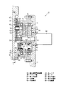
図1、2、3において、11は産業用ロボット12の第1部材としての基端側アームであり、この基端側アーム11は基端部を中心に揺動可能である。この基端側アーム11の先端部一側面には偏心揺動型減速機13の固定部、ここではケース14が複数のボルト15によって固定され、また、この偏心揺動型減速機13の回転部、ここではキャリア16の一側端には産業用ロボット12の第2部材としての先端側アーム17の基端部が複数のボルト18によって固定されている。
Embodiment 1 of the present invention will be described below with reference to the drawings.
In FIGS. 1, 2, and 3, reference numeral 11 denotes a proximal arm as a first member of the
この結果、前記先端側アーム17は基端部を中心に基端側アーム11に対して回転(揺動)することができる。そして、前述のようにケース14を固定側と、キャリア16を回転側とすると、従来多用されている形式と同一となり、従来と同様の感覚で使用することができる。ここで、前記ケース14は略円筒状を呈するとともに、その軸方向中央部内周には周方向に等距離離れた多数の内歯としてのピン歯21が設けられている。
As a result, the distal
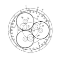
前記ケース14内には複数(2個)のピニオン22が軸方向に並べられて収納され、これらピニオン22の外周には多数のトロコイド歯形からなる外歯23がそれぞれ形成されている。ここで、前記ピニオン22の外歯23の歯数は前記ピン歯21の歯数より若干、ここでは1個だけ少なく、また、これらピニオン22とケース14とは内接した状態で外歯23とピン歯21とが噛み合っているが、2つのピニオン22の最大噛み合い部(噛み合いの最も深い部位)は 180度だけ位相がずれている。
A plurality (two) of
そして、これらピニオン22の中心軸上には貫通した中心孔24が、また、その内、外周間の中間部には軸方向に貫通した図示していない複数(3個)の貫通孔が周方向に等距離離れて形成されている。また、前記ケース14内には前記キャリア16が挿入されているが、このキャリア16はピニオン22の軸方向両外側に配置された一対の端板部28、29と、一端が端板部28に一体形成され、他端が端板部29に締結された複数(貫通孔と同数)の柱部(図示せず)とから構成され、これら柱部は前記貫通孔内にそれぞれ遊嵌されている。また、前記キャリア16、詳しくは端板部28、29の中心軸上には前記中心孔24とほぼ同径の中心孔32、33がそれぞれ形成されている。
A
36は前記キャリア16、詳しくは端板部28、29の外周とケース14の軸方向両端部内周との間に介装された一対の軸受であり、これらの軸受36によりキャリア16はケース14に対し相対回転可能に支持される。37は各ピニオン22に成形された軸方向に延びる貫通した複数(3個)のクランク孔であり、これらのクランク孔37は周方向に等距離離れるとともに、前記貫通孔と交互に配置されている。
36 is a pair of bearings interposed between the outer periphery of the
40は複数本(クランク孔37と同数)のクランク軸であり、これらのクランク軸40は周方向に等距離離れて配置されている。これらクランク軸40とキャリア16、詳しくは端板部28、29との間には軸方向に離れた一対の軸受41がそれぞれ介装され、これにより、前記クランク軸40の軸方向両端部はこれら一対の軸受41を介してキャリア16に回転可能に支持される。
また、前記クランク軸40は軸方向中央部にクランク軸40の中心軸から等距離だけ偏心したピニオン22と同数(2個)の偏心部44を有し、これら偏心部44は軸方向に隣接して配置されるとともに、互いに 180度だけ位相がずれている。そして、前記クランク軸40の偏心部44はピニオン22のクランク孔37内にそれぞれころ軸受45を介して挿入されており、この結果、前記ピニオン22とクランク軸40とは相対回転が許容されている。なお、46は軸方向一側に配置されている軸受36より軸方向一側のケース14内周とキャリア16、詳しくは端板部28の外周との間に介装されたオイルシールである。
In addition, the
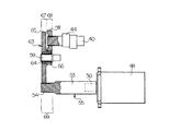
前述したケース14、キャリア16、ピニオン22、クランク軸40は全体として、クランク軸40に入力された回転を減速してケース14またはキャリア16、ここではキャリア16に出力する前記偏心揺動型減速機13を構成する。48は前記基端側アーム11の先端部でその他側面に複数のボルト49によって取付けられたモータであり、このモータ48の回転軸50は前記偏心揺動型減速機13の中心軸と同軸である。このようにモータ48と偏心揺動型減速機13とを同軸とすれば、モータが偏心揺動型減速機の中心軸から半径方向に所定距離離れて設置されている場合に比較し、旋回部構造全体を小型化することができる。
The eccentric oscillating speed reducer that decelerates the rotation input to the
この回転軸50には前記偏心揺動型減速機13の中心部に形成された中心孔24、32、33を軸方向に貫通する伝達軸53が固定され、この伝達軸53の先端(一端)には1個の第1外歯車54が設けられている。前述した回転軸50、伝達軸53は全体として、中心孔24、32、33内を軸方向一側に向かって延びるモータ48の出力軸55を構成し、この出力軸55に設けられた第1外歯車54はモータ48からの駆動力が伝達されると、軸線回りに回転する。
A
58は少なくともいずれか1本、ここでは全てのクランク軸40の軸方向片側端(軸方向一側端)にスプライン結合によりそれぞれ取り付けられた第2外歯車である。59は出力軸55に平行に延びる少なくとも1本、ここでは第2外歯車58と同数である3本の支持軸であり、これらの支持軸59は周方向に等距離離れるとともに、その軸方向他側部がキャリア16、詳しくは端板部28に挿入固定されることで該キャリア16に支持されている。
58 is a second external gear attached to at least one of them, here, one end of each
また、前記支持軸59は、第2外歯車58が取り付けられたクランク軸40、ここでは前述のように全てのクランク軸40から周方向に離れた位置に配置、詳しくは対応するクランク軸40の周方向一側に近接して配置されるとともに、全てのクランク軸40の中心軸を通る仮想円60より半径方向外側に配置されている。63は各支持軸59の軸方向一側部に軸受64を介して回転可能に支持された該支持軸59と同軸の第3外歯車であり、これらの第3外歯車63は軸方向一側に第1外歯車54より大径である大径歯車65を有し、これら全ての大径歯車65は前記1個の第1外歯車54の周囲に配置されるとともに、該1個の第1外歯車54に噛み合っている。
The
ここで、前記大径歯車65は互いに干渉し合うことのない最大径に形成されており、この結果、第1外歯車54と大径歯車65との噛み合いによって大きな減速比を得ることができる。また、前記第3外歯車63はその軸方向他側に小径歯車66を有し、該小径歯車66は前記大径歯車65に同軸関係を保って近接配置されている。そして、これら小径歯車66は前記第2外歯車58より小径であるとともに、対応する第2外歯車58にそれぞれ噛み合っている。
Here, the large-
前述した第1外歯車54、第3外歯車63の大径歯車65は全体として、第1段歯車減速機構67を、第3外歯車63の小径歯車66、第2外歯車58は全体として、第2段歯車減速機構68を構成し、これら第1、第2段歯車減速機構67、68は全体として、偏心揺動型減速機13の前段に配置された前段減速機69を構成する。ここで、前述のように、支持軸59を全てのクランク軸40の中心軸を通る仮想円60より半径方向外側に配置したので、第3外歯車63の大径歯車65の径をさらに大径とすることができ、これにより、減速装置の減速比を容易に大きくすることができる。なお、前述の支持軸59は隣接するクランク軸40の周方向中間位置上、または、その近傍にそれぞれ配置し、これにより、小径歯車66を両隣の第2外歯車58に、または、片側の第2外歯車58に噛み合わせるようにしてもよい。このようにすれば、第2外歯車58がさらに大径となり、第2段歯車減速機構68の減速比をさらに大とすることができる。
The first
さらに、大径歯車65を前述のように互いに干渉し合うことのない最大径に形成すると、端板部28の軸方向一側部には、大径歯車65を外側から囲むために、ケース14の中央部外周より半径方向外側に突出した外方フランジ71が形成されるが、このように外方フランジ71が形成されると、前記オイルシール46の開放側、即ち軸方向一側は該外方フランジ71によってほぼ閉止され、偏心揺動型減速機13の内部へのゴミの侵入が効果的に抑制される。また、前述したボルト18は外方フランジ71と先端側アーム17とに共締めされているため、偏心揺動型減速機13の中心軸からボルト18までの半径方向距離が長くなって、偏心揺動型減速機13から先端側アーム17への伝達トルクを大きなものとすることができる。
Further, when the large-
次に、前記実施例1の作用について説明する。
前述のような産業用ロボット12において先端側アーム17を基端側アーム11に対して回転(揺動)させる場合には、モータ48を作動して出力軸55を回転させる。この出力軸55の回転は、第1外歯車54および第3外歯車63の大径歯車65により、続いて第3外歯車63の小径歯車66および第2外歯車58により、次々に減速されながら全てのクランク軸40に伝達され、これらクランク軸40を自身の中心軸回りに同一方向に同一回転速度で回転させる。
Next, the operation of the first embodiment will be described.
When the
このとき、クランク軸40の偏心部44がピニオン22のクランク孔37内において偏心回転してピニオン22を偏心揺動回転させるが、前記ピニオン22の外歯23の歯数がケース14のピン歯21の数より1個だけ少ないので、キャリア16はピニオン22の偏心揺動回転により大幅に減速されて低速回転し、先端側アーム17を基端部を中心として回転(揺動)させる。
At this time, the
ここで、前述のようにキャリア16に支持された支持軸59には2段の歯車、即ち、第3外歯車63の大径歯車65、小径歯車66が支持され、一方、クランク軸40の軸方向片側端(一側端)には前記小径歯車66に噛み合う1段の第2外歯車58が取り付けられているだけであるため、減速装置全体の軸方向長が短くなり、小型化が可能となる。
Here, as described above, the
また、第1外歯車54からクランク軸40に駆動力が伝達されるまでに、歯車が2箇所、即ち、第1外歯車54と第3外歯車63の大径歯車65、第3外歯車63の小径歯車66と第2外歯車58とで噛み合うだけであるため、騒音が低減され、エネルギーロスも低下させることができる。さらに、大径歯車65、小径歯車66を有するのは第3外歯車63の1種類だけであるため、構造を簡単なものとすることもできる。
In addition, until the driving force is transmitted from the first
以下、この発明の実施例2を図面に基づいて説明する。
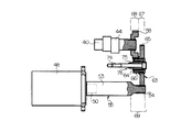
図4、5、6はこの発明の実施例2を示す図である。この実施例においては、モータ48がキャリア16の端板部28に複数のボルト49によって取り付けられるとともに、該モータ48から軸方向他側に向かって延びる出力軸55の先端(他端側)には第1外歯車54が設けられ、また、偏心揺動型減速機13のクランク軸40の軸方向片側端(軸方向他側端)には第2外歯車58が取り付けられている。
Embodiment 2 of the present invention will be described below with reference to the drawings.
4, 5 and 6 are views showing Embodiment 2 of the present invention. In this embodiment, the
さらに、この実施例では前記実施例と同様に、キャリア16が、端板部28、29と、端板部28に一体形成されピニオン22に形成された貫通孔72に遊嵌されている柱部73との少なくとも2つ以上、ここでは3つの部材から構成されているが、このうち、柱部73と端板部29とを、軸方向一側に向かってねじ込まれた締結部材としての複数(柱部73と同数)のボルト74により共締めして締結している。なお、前述の柱部73と端板部29とは、通常、前述した締結部材としてのボルト74以外のボルト、ピンによっても締結されている。
Further, in this embodiment, similarly to the above embodiment, the
そして、これらボルト74は支持軸76を構成するが、これら支持軸76(ボルト74)の外側には、軸方向他側に位置する大径歯車65と軸方向一側に位置する小径歯車66とを有する第3外歯車63が、円筒状をした中間部材75および軸受64を介してそれぞれ回転可能に支持されるとともに、これら大径歯車65は前述と同様に1個の第1外歯車54に、小径歯車66は第2外歯車58にそれぞれ噛み合っている。なお、前述の中間部材75、軸受64は省略することも可能であるが、この場合には、第3外歯車63を支持しているボルト74の外周に軸受メタル等を一体形成することが好ましい。
These
前述のようにキャリア16が2以上の部材(端板部28、29、柱部73)から構成されているとき、第3外歯車63を回転可能に支持する支持軸76(ボルト74)により前記柱部73と端板部29とを締結するようにすれば、支持軸76をキャリア16の締結用および第3外歯車63の支持用の双方に共用することができ、これにより、構造が簡単となり製作費を安価とすることもできる。なお、他の構成、作用は前記実施例1と同様である。
As described above, when the
なお、前述の実施例においては、全て(3本)のクランク軸40に第2外歯車58を取り付けるとともに、該クランク軸40と同数(3本)の支持軸59にそれぞれ第3外歯車63を支持させ、1個の第1外歯車54に3個の第3外歯車63の大径歯車65を噛み合わせる一方、3個の第3外歯車63の小径歯車66を対応する第2外歯車58にそれぞれ噛み合わせるようにしたが、この発明においては、いずれか1本のクランク軸のみに第2外歯車を取り付けるとともに、該クランク軸と、該クランク軸に隣接するクランク軸との間に設置された1本の支持軸のみに1個の第3外歯車を支持させ、第1外歯車に第3外歯車の大径歯車を、第2外歯車に第3外歯車の小径歯車を1対1で噛み合わせるようにしてもよい。このとき、モータを偏心揺動型減速機の中心軸から半径方向に所定距離離して配置してもよい。
In the embodiment described above, the second
また、前述の実施例においては、支持軸59の軸方向他側部をキャリア16(端板部28)に固定する一方、該支持軸59の軸方向一側部に軸受64を介して第3外歯車63を回転可能に支持させるようにしたが、この発明においては、支持軸をキャリアに軸受を介して回転可能に支持する一方、該支持軸に第3外歯車を固定するようにしてもよく、いずれの場合も第3外歯車は回転可能となる。また、前述の実施例においては、支持軸59をキャリア16(端板部28または29)に、アーム(先端側アーム17または基端側アーム11)側に突出するよう、支持させたが、この発明においては、支持軸をキャリア(端板部)に、ピニオン側に突出するよう、支持させてもよい。
In the above-described embodiment, the other side portion of the
また、前述の実施例においては、偏心揺動型減速機13のピン歯21の歯数とピニオン22の外歯23との歯数差が1であったが、この発明においては2以上であってもよい。さらに、前述の実施例においては、産業用ロボット12の第1部材である基端側アーム11に偏心揺動型減速機13の固定部であるケース14を取り付け、産業用ロボット12の第2部材である先端側アーム17に回転部であるキャリア16を取り付けるようにしたが、産業用ロボットの第1部材に偏心揺動型減速機の固定部であるキャリアを、第2部材に回転部であるケースを取り付けるようにしてもよい。
In the above-described embodiment, the difference in the number of teeth between the
この発明は、偏心揺動型減速機に適用できる。 This invention is applicable to an eccentric oscillating speed reducer.
13…偏心揺動型減速機 16…キャリア
40…クランク軸 48…モータ
54…第1外歯車 58…第2外歯車
59…支持軸 63…第3外歯車
65…大径歯車 66…小径歯車
74…締結部材 75…中間部材
76…支持軸
13 ... Eccentric
40 ...
54 ... 1st
59 ...
65 ...
74 ... Fastening
76 ... Support shaft
Claims (1)
Priority Applications (1)
| Application Number | Priority Date | Filing Date | Title |
|---|---|---|---|
| JP2007259473A JP4804439B2 (en) | 2007-10-03 | 2007-10-03 | Reducer |
Applications Claiming Priority (1)
| Application Number | Priority Date | Filing Date | Title |
|---|---|---|---|
| JP2007259473A JP4804439B2 (en) | 2007-10-03 | 2007-10-03 | Reducer |
Related Parent Applications (1)
| Application Number | Title | Priority Date | Filing Date |
|---|---|---|---|
| JP2005232877A Division JP4901156B2 (en) | 2005-08-11 | 2005-08-11 | Reduction gear |
Publications (3)
| Publication Number | Publication Date |
|---|---|
| JP2008014500A JP2008014500A (en) | 2008-01-24 |
| JP2008014500A5 JP2008014500A5 (en) | 2008-03-27 |
| JP4804439B2 true JP4804439B2 (en) | 2011-11-02 |
Family
ID=39071693
Family Applications (1)
| Application Number | Title | Priority Date | Filing Date |
|---|---|---|---|
| JP2007259473A Active JP4804439B2 (en) | 2007-10-03 | 2007-10-03 | Reducer |
Country Status (1)
| Country | Link |
|---|---|
| JP (1) | JP4804439B2 (en) |
Families Citing this family (3)
| Publication number | Priority date | Publication date | Assignee | Title |
|---|---|---|---|---|
| US8920278B2 (en) | 2008-08-21 | 2014-12-30 | Nabtesco Corporation | Gear transmission and photovoltaic power-generating apparatus using the gear transmission |
| JP5352176B2 (en) * | 2008-10-09 | 2013-11-27 | ナブテスコ株式会社 | Eccentric oscillating gear transmission |
| JP5917421B2 (en) * | 2013-01-29 | 2016-05-11 | 住友重機械工業株式会社 | Series of eccentric oscillating speed reducers |
Family Cites Families (2)
| Publication number | Priority date | Publication date | Assignee | Title |
|---|---|---|---|---|
| JP2827166B2 (en) * | 1998-03-13 | 1998-11-18 | 帝人製機株式会社 | Planetary gear reducer |
| JP4020560B2 (en) * | 2000-02-07 | 2007-12-12 | ナブテスコ株式会社 | Eccentric rocking speed reducer |
-
2007
- 2007-10-03 JP JP2007259473A patent/JP4804439B2/en active Active
Also Published As
| Publication number | Publication date |
|---|---|
| JP2008014500A (en) | 2008-01-24 |
Similar Documents
| Publication | Publication Date | Title |
|---|---|---|
| JP4901156B2 (en) | Reduction gear | |
| JP5356462B2 (en) | Turning structure of industrial robot using eccentric rocking type reducer | |
| JP4897747B2 (en) | Swing type planetary gear unit | |
| JP2008249149A5 (en) | ||
| JP2001221298A (en) | Eccentric oscillating reduction gear | |
| JP4804439B2 (en) | Reducer | |
| JP2007078010A (en) | Industrial robot swivel structure | |
| JP2008014500A5 (en) | ||
| JP3688230B2 (en) | Eccentric differential reducer | |
| JP4925992B2 (en) | Eccentric differential reducer and swivel structure using the eccentric differential reducer | |
| JP4219320B2 (en) | Robot swivel structure | |
| JP2008025846A5 (en) | ||
| JP4845791B2 (en) | Eccentric oscillating gear mechanism | |
| JP4437457B2 (en) | Industrial robot swivel structure | |
| JP4999978B2 (en) | Eccentric differential reducer | |
| JP4632852B2 (en) | Industrial robot swivel structure | |
| JP4947770B2 (en) | Decelerator | |
| JP2008062377A (en) | Turning part structure for robots, etc. | |
| JP2007056984A (en) | Hypocycloid gear reducer | |
| JP4707499B2 (en) | Rotation drive mechanism | |
| JP2007075913A (en) | Industrial robot swivel structure | |
| JP2008023711A (en) | Turning part structure for robots, etc. | |
| JP2006070963A (en) | Epicycle reduction gear | |
| JP2008045670A (en) | Transmission |
Legal Events
| Date | Code | Title | Description |
|---|---|---|---|
| A521 | Request for written amendment filed |
Free format text: JAPANESE INTERMEDIATE CODE: A523 Effective date: 20080213 |
|
| A621 | Written request for application examination |
Free format text: JAPANESE INTERMEDIATE CODE: A621 Effective date: 20080226 |
|
| A521 | Request for written amendment filed |
Free format text: JAPANESE INTERMEDIATE CODE: A523 Effective date: 20080325 |
|
| A977 | Report on retrieval |
Free format text: JAPANESE INTERMEDIATE CODE: A971007 Effective date: 20101201 |
|
| A131 | Notification of reasons for refusal |
Free format text: JAPANESE INTERMEDIATE CODE: A131 Effective date: 20110524 |
|
| A521 | Request for written amendment filed |
Free format text: JAPANESE INTERMEDIATE CODE: A523 Effective date: 20110722 |
|
| TRDD | Decision of grant or rejection written | ||
| A01 | Written decision to grant a patent or to grant a registration (utility model) |
Free format text: JAPANESE INTERMEDIATE CODE: A01 Effective date: 20110809 |
|
| A01 | Written decision to grant a patent or to grant a registration (utility model) |
Free format text: JAPANESE INTERMEDIATE CODE: A01 |
|
| A61 | First payment of annual fees (during grant procedure) |
Free format text: JAPANESE INTERMEDIATE CODE: A61 Effective date: 20110809 |
|
| R150 | Certificate of patent or registration of utility model |
Ref document number: 4804439 Country of ref document: JP Free format text: JAPANESE INTERMEDIATE CODE: R150 Free format text: JAPANESE INTERMEDIATE CODE: R150 |
|
| FPAY | Renewal fee payment (event date is renewal date of database) |
Free format text: PAYMENT UNTIL: 20140819 Year of fee payment: 3 |
|
| FPAY | Renewal fee payment (event date is renewal date of database) |
Free format text: PAYMENT UNTIL: 20140819 Year of fee payment: 3 |
|
| S531 | Written request for registration of change of domicile |
Free format text: JAPANESE INTERMEDIATE CODE: R313531 |
|
| FPAY | Renewal fee payment (event date is renewal date of database) |
Free format text: PAYMENT UNTIL: 20140819 Year of fee payment: 3 |
|
| R350 | Written notification of registration of transfer |
Free format text: JAPANESE INTERMEDIATE CODE: R350 |
|
| R250 | Receipt of annual fees |
Free format text: JAPANESE INTERMEDIATE CODE: R250 |
|
| R250 | Receipt of annual fees |
Free format text: JAPANESE INTERMEDIATE CODE: R250 |
|
| R250 | Receipt of annual fees |
Free format text: JAPANESE INTERMEDIATE CODE: R250 |
|
| R250 | Receipt of annual fees |
Free format text: JAPANESE INTERMEDIATE CODE: R250 |
|
| R250 | Receipt of annual fees |
Free format text: JAPANESE INTERMEDIATE CODE: R250 |
|
| R250 | Receipt of annual fees |
Free format text: JAPANESE INTERMEDIATE CODE: R250 |
|
| R250 | Receipt of annual fees |
Free format text: JAPANESE INTERMEDIATE CODE: R250 |
|
| R250 | Receipt of annual fees |
Free format text: JAPANESE INTERMEDIATE CODE: R250 |
|
| R250 | Receipt of annual fees |
Free format text: JAPANESE INTERMEDIATE CODE: R250 |