JP5708043B2 - Pneumatic tire - Google Patents
Pneumatic tire Download PDFInfo
- Publication number
- JP5708043B2 JP5708043B2 JP2011046813A JP2011046813A JP5708043B2 JP 5708043 B2 JP5708043 B2 JP 5708043B2 JP 2011046813 A JP2011046813 A JP 2011046813A JP 2011046813 A JP2011046813 A JP 2011046813A JP 5708043 B2 JP5708043 B2 JP 5708043B2
- Authority
- JP
- Japan
- Prior art keywords
- recess
- ridge portion
- display mark
- ridge
- pneumatic tire
- Prior art date
- Legal status (The legal status is an assumption and is not a legal conclusion. Google has not performed a legal analysis and makes no representation as to the accuracy of the status listed.)
- Expired - Fee Related
Links
Images


Description
この発明は、空気入りタイヤに関し、さらに詳しくは、サイドウォール部の表示マークの視認性を向上させ得る空気入りタイヤに関する。 The present invention relates to a pneumatic tire, and more particularly, to a pneumatic tire that can improve the visibility of display marks on a sidewall portion.
一般的な空気入りタイヤは、サイドウォール部の表面に表示マークを有する。この表示マークは、タイヤの製造業者や種別などを表示するマークであり、文字、図形、記号などから構成される。この表示マークは、サイドウォール部と同一色のゴム材料から成る場合があり、必ずしも視認性が良くない。このため、タイヤのブランドイメージを強調するなどの理由から、表示マークの視認性を向上させるべき課題がある。 A general pneumatic tire has a display mark on the surface of the sidewall portion. This display mark is a mark for displaying the manufacturer and type of the tire, and is composed of characters, figures, symbols, and the like. This display mark may be made of a rubber material having the same color as the side wall portion, and is not always highly visible. For this reason, there exists a subject which should improve the visibility of a display mark for the reason of emphasizing the brand image of a tire.
このような課題に関する従来の空気入りタイヤとして、特許文献1〜3に記載される技術が知られている。
As conventional pneumatic tires relating to such problems, techniques described in
この発明は、サイドウォール部の表示マークの視認性を向上させ得る空気入りタイヤを提供することを目的とする。 An object of the present invention is to provide a pneumatic tire that can improve the visibility of the display mark on the sidewall portion.
上記目的を達成するため、この発明にかかる空気入りタイヤは、サイドウォール部の表面に表示マークを備える空気入りタイヤであって、前記表示マークが、前記表示マークの表示内容を識別するための主要部となる所定の文字、図形または記号の輪郭を形成すると共にサイドウォール部のプロファイル面に対して凹となる第一凹部と、前記第一凹部内に形成される第一リッジ部と、前記第一凹部の輪郭に沿って配置されると共にサイドウォール部のプロファイル面に対して凹となる第二凹部と、前記第二凹部内に形成される第二リッジ部とを備え、且つ、前記第二リッジ部が前記第一リッジ部よりも密に配置されることを特徴とする。 In order to achieve the above object, a pneumatic tire according to the present invention is a pneumatic tire provided with a display mark on a surface of a sidewall portion, wherein the display mark is a main part for identifying display contents of the display mark. Forming a contour of a predetermined character, figure or symbol to be a part and being concave with respect to the profile surface of the sidewall part, a first ridge part formed in the first concave part, and the first A second recess disposed along the contour of the recess and recessed with respect to the profile surface of the sidewall, and a second ridge formed in the second recess, and the second The ridge portion is arranged more densely than the first ridge portion.
また、この発明にかかる空気入りタイヤは、前記表示マークの平面視にて、前記第二凹部が前記第一凹部の輪郭を基準とした投影図に基づいて規定された陰影を構成することが好ましい。
また、この発明にかかる空気入りタイヤは、前記第二凹部が、前記第一凹部の輪郭の全周を囲んで配置されることが好ましい。
In the pneumatic tire according to the present invention, it is preferable that the second recess constitutes a shadow defined based on a projection view based on an outline of the first recess in a plan view of the display mark . .
In the pneumatic tire according to the present invention, it is preferable that the second recess is disposed so as to surround the entire circumference of the outline of the first recess.
また、この発明にかかる空気入りタイヤは、前記第二リッジ部のピッチP2と前記第一リッジ部のピッチP1とが0.1≦P2/P1≦0.8の範囲内にあることが好ましい。 In the pneumatic tire according to the present invention, it is preferable that the pitch P2 of the second ridge portion and the pitch P1 of the first ridge portion are in a range of 0.1 ≦ P2 / P1 ≦ 0.8.
また、この発明にかかる空気入りタイヤは、前記第一凹部と前記第二凹部とが連通することが好ましい。
また、この発明にかかる空気入りタイヤは、前記第一凹部と前記第二凹部との間に形成された境界壁を備えることが好ましい。
In the pneumatic tire according to the present invention, it is preferable that the first recess and the second recess communicate with each other.
Moreover, it is preferable that the pneumatic tire according to the present invention includes a boundary wall formed between the first recess and the second recess.
この発明にかかる空気入りタイヤでは、第二リッジ部が第一リッジ部よりも密に配置されるので、表示マークの平面視にて、第一リッジ部側の領域(第一凹部)と第二リッジ部側の領域(第二凹部)との相異が際立つ。これにより、第一リッジ部側の領域が強調されて、サイドウォール部の表示マークの視認性が向上する利点がある。 In the pneumatic tire according to the present invention, since the second ridge portion is arranged more densely than the first ridge portion, the region on the first ridge portion side (first concave portion) and the second ridge portion are seen in plan view of the display mark. The difference from the region on the ridge portion side (second concave portion) stands out. Thereby, there is an advantage that the region on the first ridge portion side is emphasized and the visibility of the display mark on the sidewall portion is improved.
以下、この発明につき図面を参照しつつ詳細に説明する。なお、この実施の形態によりこの発明が限定されるものではない。また、この実施の形態の構成要素には、発明の同一性を維持しつつ置換可能かつ置換自明なものが含まれる。また、この実施の形態に記載された複数の変形例は、当業者自明の範囲内にて任意に組み合わせが可能である。 Hereinafter, the present invention will be described in detail with reference to the drawings. Note that the present invention is not limited to the embodiments. Further, the constituent elements of this embodiment include those that can be replaced while maintaining the identity of the invention and that are obvious for replacement. In addition, a plurality of modifications described in this embodiment can be arbitrarily combined within a range obvious to those skilled in the art.
[空気入りタイヤ]
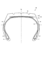
図1は、この発明の実施の形態にかかる空気入りタイヤを示すタイヤ子午線方向の断面図である。同図は、乗用車用ラジアルタイヤを示している。
[Pneumatic tire]
FIG. 1 is a sectional view in the tire meridian direction showing a pneumatic tire according to an embodiment of the present invention. The figure shows a radial tire for a passenger car.
空気入りタイヤ10は、一対のビードコア11、11と、一対のビードフィラー12、12と、カーカス層13と、ベルト層14と、トレッドゴム15と、一対のサイドウォールゴム16、16とを備える(図1参照)。一対のビードコア11、11は、環状構造を有し、左右のビード部のコアを構成する。ビードフィラー12は、一対のビードコア11、11のタイヤ径方向外周に配置されてビード部を補強する。カーカス層13は、左右のビードコア11、11間にトロイダル状に架け渡されてタイヤの骨格を構成する。ベルト層14は、積層された一対のベルトプライ141、142から成り、カーカス層13のタイヤ径方向外周に配置される。トレッドゴム15は、カーカス層13およびベルト層14のタイヤ径方向外周に配置されてタイヤのトレッド部を構成する。一対のサイドウォールゴム16、16は、カーカス層13のタイヤ幅方向外側にそれぞれ配置されて左右のサイドウォール部を構成する。
The
[表示マーク]
図2は、図1に記載した空気入りタイヤの表示マークを示す平面図である。同図は、タイヤのサイドトレッドを平面視したときの表示マークの様子を示している。また、図3は、図2に記載した表示マークを示すA−A視断面図である。
[Display mark]
FIG. 2 is a plan view showing display marks of the pneumatic tire shown in FIG. The figure shows the state of the display mark when the tire side tread is viewed in plan. 3 is a cross-sectional view taken along line AA showing the display mark shown in FIG.
空気入りタイヤ10は、サイドウォール部の表面に表示マーク1を備える(図1〜図3参照)。この表示マーク1は、タイヤの製造業者や種別などを表示するマークであり、文字、図形、記号などから構成される。
The
表示マーク1は、第一凹部21と、第一リッジ部22と、第二凹部31と、第二リッジ部32とを備える(図2および図3参照)。
The
第一凹部21は、所定の文字、図形または記号の輪郭を形成する部分であり、表示マーク1の表示内容を識別するための主要部となる。また、第一凹部21は、サイドウォール部のプロファイル面に対して凹となる。例えば、この実施の形態では、第一凹部21が文字「Y」の輪郭を有することにより、表示マーク1が文字「Y」をデザインした図形となっている。また、第一凹部21が、その全域に渡って一定の深さA1を有している。
The
第一リッジ部22は、第一凹部21内に形成されるリッジである。リッジとは、凸部あるいは凹凸部をいう。この第一リッジ部22は、表示マーク1の平面視にて、第一凹部21を埋めるハッチングとなり、第一リッジ部22の視認性を向上させる。例えば、この実施の形態では、第一リッジ部22が台形断面を有するリブ状の凸部であり、複数の第一リッジ部22が第一凹部21の全域に渡って所定のピッチP1で配置されている。
The
第二凹部31は、第一凹部21の輪郭に沿って配置される領域であり、第一凹部21の輪郭を際立たせるために設けられる。また、第二凹部31は、サイドウォール部のプロファイル面に対して凹となる。例えば、この実施の形態では、表示マーク1の平面視にて、第二凹部31が第一凹部21の輪郭の陰影に見えるように、第一凹部21の外周に配置されている。具体的には、第一凹部21の輪郭を基準とした投影図に基づいて、第二凹部31の形状および位置が規定されている。
The
第二リッジ部32は、第二凹部31内に形成されるリッジである。この第二リッジ部32は、表示マーク1の平面視にて、第二凹部31を埋めるハッチングとなり、第二凹部31の作用(第一凹部21の輪郭を際立たせる作用)を向上させる。例えば、この実施の形態では、第二リッジ部32が三角形断面を有するリブ状の凸部であり、複数の第二リッジ部32が第二凹部31の全域に渡って所定のピッチP2で配置されている。
The
また、第二リッジ部32は、第一リッジ部22よりも密に配置される(図2および図3参照)。言い換えると、第一リッジ部22は、第二リッジ部32よりも疎に配置される。例えば、この実施の形態では、第二リッジ部32のピッチP2が第一リッジ部22のピッチP1よりも狭く(P2<P1)、また、隣り合う第二リッジ部32、32の間隔(溝幅)が隣り合う第一リッジ部22、22の間隔よりも狭くなっている。また、このとき、第二リッジ部32のピッチP2と第一リッジ部22のピッチP1とが0.1≦P2/P1≦0.8の範囲内にあることが好ましい(図3参照)。これにより、表示マーク1の平面視にて、第一リッジ部22側の領域(第一凹部21)と第二リッジ部32側の領域(第二凹部31)との相異が際立って、表示マーク1の視認性が向上する。
The
なお、表示マーク1は、サイドウォールゴム16の一部により構成される。具体的には、タイヤ成形金型が表示マーク1に対応した凹凸部を有する(図示省略)。そして、タイヤの加硫成形時にて、この凹凸部の形状がサイドウォールゴム16に転写されて、サイドウォール部に表示マーク1が成形される。また、表示マーク1は、他のサイドウォールゴム16の部分に対して同一色のゴム材料から構成されても良いし、相互に異色のゴム材料から構成されても良い。
The
[変形例]
図4〜図7は、図2に記載した表示マークの変形例を示す説明図である。これらの図において、図2および図3に記載した表示マークと同一の構成要素には同一の符号を付し、その説明を省略する。
[Modification]
4 to 7 are explanatory diagrams illustrating modifications of the display mark described in FIG. In these drawings, the same components as those of the display marks described in FIGS. 2 and 3 are denoted by the same reference numerals, and the description thereof is omitted.
この実施の形態では、第一凹部21が文字「Y」の輪郭を有することにより、表示マーク1が文字「Y」をデザインした図形となっている(図2参照)。一方、図4に示す変形例では、第一凹部21が文字「O」の輪郭を有することにより、表示マーク1が文字「O」をデザインした図形となっている。このように、表示マーク1が閉環形状を有する場合には、その内部にも第二凹部31および第二リッジ部32が配置され得る。
In this embodiment, the
また、この実施の形態では、第一凹部21の深さA1と、第二凹部31の深さA2とが等しく(A1=A2)設定されている(図3参照)。しかし、これに限らず、第一凹部21の深さA1と第二凹部31の深さA2とが相異しても良い(図示省略)。
In this embodiment, the depth A1 of the
また、この実施の形態では、第一凹部21の深さA1と、第一リッジ部22の高さB1とがA1>B1の関係を有している(図3参照)。同様に、第二凹部31の深さA2と、第二リッジ部32の高さB2とがA2>B2の関係を有している。したがって、第一リッジ部22および第二リッジ部32が、サイドウォール部のプロファイルラインよりもタイヤ内部側にあり、サイドウォール部から突出していない。かかる構成では、表示マーク1がサイドウォール部のプロファイル面に対して凹となるので、サイドウォール部の空気抵抗が減少するため、好ましい。
In this embodiment, the depth A1 of the
なお、第一凹部21の深さA1と第一リッジ部22の高さB1との比B1/A1、ならびに、第二凹部31の深さA2と第二リッジ部32の高さB2との比B2/A2は、0.2≦B1/A1≦1.0かつ0.2≦B2/A2≦1.0の範囲内にあることが好ましい。また、上限については、B1/A1≦0.9かつB2/A2≦0.9であることがより好ましい。これにより、サイドウォール部の空気抵抗を低減しつつ、表示マーク1の視認性を向上できる。
In addition, ratio B1 / A1 of depth A1 of the 1st recessed
また、この実施の形態では、表示マーク1の平面視にて、第二凹部31が第一凹部21の輪郭に対する陰影を構成している(図2参照)。かかる構成では、第一凹部21の輪郭が立体的に見える点で好ましい。しかし、これに限らず、第二凹部31が第一凹部21の輪郭の全周を囲んで配置されても良い(図5参照)。これにより、表示マーク1の視認性が向上する。
Moreover, in this embodiment, the second recessed
また、この実施の形態では、第一リッジ部22および第二リッジ部32が相互に同一方向に延在している(図2参照)。具体的には、第一リッジ部22および第二リッジ部32がタイヤ径方向に対して45[deg]の角度で相互に同一方向に傾斜している。しかし、これに限らず、第一リッジ部22および第二リッジ部32が相互に異なる方向に傾斜しても良い(図示省略)。また、第一リッジ部22および第二リッジ部32がタイヤ径方向に対して任意の角度で傾斜しても良い(図示省略)。
In this embodiment, the
また、この実施の形態では、第一リッジ部22が直線状のリブ状形状を有している(図2参照)。しかし、これに限らず、第一リッジ部22が、例えば、曲線状のリブ状形状、メッシュ形状、点在する突起形状などの任意の形状を有し得る(図示省略)。同様に、第二リッジ部32も、任意の形状を有し得る。例えば、図6の変形例では、表示マーク1の平面視にて、第一リッジ部22が円弧状のリブ状形状を有し、第二リッジ部32がメッシュ形状を有している。
Moreover, in this embodiment, the
また、この実施の形態では、第一リッジ部22が凸部となっている(図3参照)。しかし、これに限らず、第一リッジ部22が凹凸部であっても良い(図示省略)。すなわち、第一リッジ部22が、第一凹部21内に形成された凹凸部であっても良い。例えば、第一リッジ部22が、第一凹部21の底面を基準とした波状断面形状を有しても良いし、突起およびディンプルの組み合わせから成る凹凸形状を有しても良い。同様に、第二リッジ部32が第二凹部31内に形成された凹凸部であっても良い。
Further, in this embodiment, the
また、この実施の形態では、第一リッジ部22が台形断面形状を有している(図3参照)。しかし、これに限らず、第一リッジ部22が、例えば、矩形断面形状、円弧断面形状、三角形断面形状など、任意の断面形状を有しても良い(図示省略)。ただし、第一リッジ部22が第一凹部21の底面に対して凸となる部分を少なくとも一部に有することを要する。同様に、この実施の形態では、第二リッジ部32が三角形断面形状を有するが(図3参照)、これに限らず、第二リッジ部32が任意の断面形状を有しても良い(図示省略)。
Further, in this embodiment, the
また、この実施の形態では、第一凹部21と第二凹部31とが連通している(図3参照)。具体的には、第一凹部21と第二凹部31とが境界壁を有することなく隣接して、単一の凹部を形成している。かかる構成では、タイヤ加硫成形時にて、表示マーク1内におけるエア溜まりの発生が抑制されるので、好ましい。しかし、これに限らず、第一凹部21と第二凹部31との間に境界壁4が形成されても良い(図7参照)。
Moreover, in this embodiment, the 1st recessed
[効果]
以上説明したように、この空気入りタイヤ10は、サイドウォール部の表面に表示マーク1を備える(図1および図2参照)。また、表示マーク1が、所定の文字、図形または記号の輪郭を形成すると共にサイドウォール部のプロファイル面に対して凹となる第一凹部21と、この第一凹部21内に形成される第一リッジ部22と、第一凹部21の輪郭に沿って配置されると共にサイドウォール部のプロファイル面に対して凹となる第二凹部31と、この第二凹部31内に形成される第二リッジ部32とを備える(図2および図3参照)。そして、第二リッジ部32が第一リッジ部22よりも密に配置される。
[effect]
As described above, the
かかる構成では、第二リッジ部32が第一リッジ部22よりも密に配置されるので、表示マーク1の平面視にて、第一リッジ部22側の領域(第一凹部21)と第二リッジ部32側の領域(第二凹部31)との相異が際立つ(図2参照)。これにより、第一リッジ部22側の領域が強調されて、サイドウォール部の表示マーク1の視認性が向上する利点がある。
In such a configuration, since the
なお、第二リッジ部32が第一リッジ部22よりも密に配置されるとは、第二リッジ部32のピッチP2と第一リッジ部22のピッチP1とがP2/P1<1.0であることを意味する。
The
また、この空気入りタイヤ10では、表示マーク1の平面視にて、第二凹部31が第一凹部21の輪郭に対する陰影を構成する(図2参照)。かかる構成では、第一凹部21の輪郭が立体的に見えるので、表示マーク1の立体感が向上する利点がある。
Moreover, in this
また、この空気入りタイヤ10では、第二リッジ部32のピッチP2と第一リッジ部22のピッチP1とが0<P2/P1≦0.8の範囲内にある(図3参照)。かかる構成では、第二リッジ部32のピッチP2が第一リッジ部22のピッチP1よりも密となるので、本体部である第一凹部21の輪郭が強調される。これにより、表示マーク1の視認性が向上する利点がある。
Further, in this
また、この空気入りタイヤ10では、第一凹部21と第二凹部31とが連通する(図3参照)。かかる構成では、タイヤ加硫成形時にて、表示マーク1内におけるエア溜まりの発生が抑制される。これにより、タイヤの加硫故障が抑制される利点がある。
Moreover, in this
図8は、この発明の実施の形態にかかる空気入りタイヤの性能試験の結果を示す表である。この性能試験では、相互に異なる表示マークを有する複数の空気入りタイヤについて、表示マークの(1)視認性および(2)立体感に関する評価が行われた。なお、試作タイヤのタイヤサイズは、195/65R15である。 FIG. 8 is a table showing the results of the performance test of the pneumatic tire according to the embodiment of the present invention. In this performance test, (1) visibility and (2) stereoscopic effect of the display mark were evaluated for a plurality of pneumatic tires having different display marks. The tire size of the prototype tire is 195 / 65R15.
(1)視認性および(2)立体感に関する評価では、複数人の観察者によって各サンプルを評価した。具体的には、各観察者がそれぞれ視認性と立体感について「極めて良好」、「良好」の2段階で評価を行い、全ての観察者のうち75%以上が「良好」以上で判断した場合の評価結果を3とし、全ての観察者のうち90%が「良好」以上で判断した場合の評価結果を4とし、全ての観察者のうち90%が「極めて良好」と判断した場合の評価結果を5とし、全ての観察者のうち50%以上が「良好」以上で判断した場合の評価結果を2とし、それ未満の場合を1とした。 In the evaluation regarding (1) visibility and (2) stereoscopic effect, each sample was evaluated by a plurality of observers. Specifically, when each observer evaluates visibility and stereoscopic effect in two levels, “very good” and “good”, and more than 75% of all observers judge “good” or better. The evaluation result is 3 and 90% of all observers are judged as “good” or higher, and the evaluation result is 4 and 90% of all observers are judged as “very good”. The result was set to 5, the evaluation result when 50% or more of all the observers judged “good” or more was set to 2, and the case of less than 1 was set to 1.
実施例1〜5の空気入りタイヤ10は、所定の文字をデザインした表示マーク1を有する。表示マーク1は、文字の本体部が、文字の輪郭を形成する第一凹部21と、この第一凹部21内に形成される第一リッジ部22とから成り、また、文字の外周部が、第一凹部21の輪郭に沿って配置される第二凹部31と、この第二凹部31内に形成される第二リッジ部32とから成る(図2および図3参照)。また、第二リッジ部32が第一リッジ部22よりも密(ピッチ比P2/P1<1.0)に配置される。
The
従来例の空気入りタイヤでは、表示マークが文字の輪郭を形成する第一凹部のみから成り、リッジ部や文字外周部の凹部を有していない。比較例1の空気入りタイヤでは、表示マークが、文字の本体部となる第一凹部と文字の外周部にある第二凹部とから成るが、リッジ部を有さない。比較例2の空気入りタイヤでは、表示マークが第一凹部、第一リッジ部、第二凹部および第二リッジ部とから成るが、第一リッジ部と第二リッジ部とが同一のピッチ比P2/P1を有する。 In the conventional pneumatic tire, the display mark is composed only of the first concave portion that forms the outline of the character, and does not have the concave portion of the ridge portion or the outer peripheral portion of the character. In the pneumatic tire of Comparative Example 1, the display mark is composed of the first concave portion that is the main body portion of the character and the second concave portion that is the outer peripheral portion of the character, but does not have the ridge portion. In the pneumatic tire of Comparative Example 2, the display mark includes the first concave portion, the first ridge portion, the second concave portion, and the second ridge portion, but the first ridge portion and the second ridge portion have the same pitch ratio P2. / P1.
試験結果に示すように、実施例1〜5の空気入りタイヤ10では、従来例の空気入りタイヤと比較して、表示マーク1の視認性および立体感が向上することが分かる。また、実施例1、2を比較すると、文字外周部にある第二凹部を文字の陰影とすることで、表示マーク1の立体感が向上することが分かる。また、実施例1、3を比較すると、第一リッジ部と第二リッジ部とのピッチ比P2/P1が適正化されることにより、表示マーク1の視認性が向上することが分かる。また、実施例1、4、5を比較すると、表示マーク1のリッジ部の高さ比(ここでは、B1/A1=B2/A2。図3参照。)が適正化されることにより、表示マーク1の視認性が向上することが分かる。
As shown in the test results, in the
1 表示マーク、4 境界壁、10 空気入りタイヤ、11 ビードコア、12 ビードフィラー、13 カーカス層、14 ベルト層、141、142 ベルトプライ、15 トレッドゴム、16 サイドウォールゴム、21 第一凹部、22 第一リッジ部、31 第二凹部、32 第二リッジ部
DESCRIPTION OF
Claims (6)
前記表示マークが、前記表示マークの表示内容を識別するための主要部となる所定の文字、図形または記号の輪郭を形成すると共にサイドウォール部のプロファイル面に対して凹となる第一凹部と、前記第一凹部内に形成される第一リッジ部と、前記第一凹部の輪郭に沿って配置されると共にサイドウォール部のプロファイル面に対して凹となる第二凹部と、前記第二凹部内に形成される第二リッジ部とを備え、且つ、
前記第二リッジ部が前記第一リッジ部よりも密に配置されることを特徴とする空気入りタイヤ。 A pneumatic tire having a display mark on the surface of the sidewall portion,
The display mark forms a contour of a predetermined character, figure, or symbol that is a main part for identifying the display content of the display mark, and a first recess that is recessed with respect to the profile surface of the sidewall part, A first ridge formed in the first recess, a second recess disposed along the contour of the first recess and recessed with respect to the profile surface of the sidewall, and in the second recess And a second ridge portion formed on
The pneumatic tire according to claim 1, wherein the second ridge portion is arranged more densely than the first ridge portion.
Priority Applications (1)
| Application Number | Priority Date | Filing Date | Title |
|---|---|---|---|
| JP2011046813A JP5708043B2 (en) | 2011-03-03 | 2011-03-03 | Pneumatic tire |
Applications Claiming Priority (1)
| Application Number | Priority Date | Filing Date | Title |
|---|---|---|---|
| JP2011046813A JP5708043B2 (en) | 2011-03-03 | 2011-03-03 | Pneumatic tire |
Publications (2)
| Publication Number | Publication Date |
|---|---|
| JP2012183869A JP2012183869A (en) | 2012-09-27 |
| JP5708043B2 true JP5708043B2 (en) | 2015-04-30 |
Family
ID=47014345
Family Applications (1)
| Application Number | Title | Priority Date | Filing Date |
|---|---|---|---|
| JP2011046813A Expired - Fee Related JP5708043B2 (en) | 2011-03-03 | 2011-03-03 | Pneumatic tire |
Country Status (1)
| Country | Link |
|---|---|
| JP (1) | JP5708043B2 (en) |
Families Citing this family (9)
| Publication number | Priority date | Publication date | Assignee | Title |
|---|---|---|---|---|
| FR3007324B1 (en) * | 2013-06-20 | 2015-07-17 | Michelin & Cie | PNEUMATIC COMPRISING A HIGH CONTRAST MARKING |
| FR3007325B1 (en) * | 2013-06-21 | 2016-02-12 | Michelin & Cie | PNEUMATIC COMPRISING A HIGH CONTRAST MARKING |
| JP6305889B2 (en) * | 2014-09-19 | 2018-04-04 | 東洋ゴム工業株式会社 | Pneumatic tire |
| US10596857B2 (en) | 2014-10-27 | 2020-03-24 | Bridgestone Corporation | Pneumatic tire |
| JP6392076B2 (en) * | 2014-10-27 | 2018-09-19 | 株式会社ブリヂストン | Pneumatic tire |
| JP6944412B2 (en) * | 2018-06-22 | 2021-10-06 | 株式会社ブリヂストン | tire |
| JP6947696B2 (en) * | 2018-06-22 | 2021-10-13 | 株式会社ブリヂストン | tire |
| JP7120058B2 (en) * | 2019-02-05 | 2022-08-17 | 住友ゴム工業株式会社 | tire |
| JP2023123111A (en) * | 2022-02-24 | 2023-09-05 | 住友ゴム工業株式会社 | tire |
Family Cites Families (7)
| Publication number | Priority date | Publication date | Assignee | Title |
|---|---|---|---|---|
| US4198774A (en) * | 1977-11-18 | 1980-04-22 | The Goodyear Tire & Rubber Company | Indicia for rubber articles |
| US4823856A (en) * | 1984-12-19 | 1989-04-25 | The Goodyear Tire & Rubber Company | Serrated outline marking for a tire side wall |
| GB8617409D0 (en) * | 1986-07-16 | 1986-08-20 | Sp Tyres Uk Ltd | Tyre sidewalls |
| JPH01311905A (en) * | 1988-06-10 | 1989-12-15 | Toyo Tire & Rubber Co Ltd | Tire |
| JPH09226328A (en) * | 1996-02-23 | 1997-09-02 | Bridgestone Corp | Pneumatic tire having mark formed by many ridges |
| JP4449203B2 (en) * | 2000-10-27 | 2010-04-14 | 横浜ゴム株式会社 | Pneumatic tire |
| JP5160345B2 (en) * | 2008-08-26 | 2013-03-13 | 東洋ゴム工業株式会社 | Pneumatic tire |
-
2011
- 2011-03-03 JP JP2011046813A patent/JP5708043B2/en not_active Expired - Fee Related
Also Published As
| Publication number | Publication date |
|---|---|
| JP2012183869A (en) | 2012-09-27 |
Similar Documents
| Publication | Publication Date | Title |
|---|---|---|
| JP5708043B2 (en) | Pneumatic tire | |
| JP6574770B2 (en) | Tire with a specific texture on the sidewall | |
| KR20100128228A (en) | Pneumatic tire | |
| JP5785530B2 (en) | Pneumatic tire | |
| JP5516765B1 (en) | Pneumatic tire | |
| JP2016088338A (en) | Pneumatic tire | |
| WO2007136091A1 (en) | Pneumatic tire | |
| JP5702768B2 (en) | Pneumatic tire | |
| JP2010052471A (en) | Pneumatic tire | |
| JP5545901B1 (en) | tire | |
| JP2013129233A (en) | Pneumatic tire and method for manufacturing the same | |
| JP2015140100A (en) | pneumatic tire | |
| JP2015042537A (en) | Pneumatic tire | |
| JP4725464B2 (en) | Pneumatic tire | |
| JP2012131283A (en) | Pneumatic tire | |
| CN111051084B (en) | Pneumatic tire | |
| CN112423999B (en) | Pneumatic tire | |
| JP2021102407A (en) | Pneumatic tire | |
| JP2016060419A (en) | Pneumatic tire | |
| JP5917118B2 (en) | Pneumatic tire | |
| CN112384381B (en) | Pneumatic tire | |
| JP2014159178A (en) | Tire for rough terrain running vehicle | |
| JP2023032836A (en) | pneumatic tire | |
| JP2018052173A (en) | Pneumatic tire | |
| JP2021104745A (en) | Pneumatic tire |
Legal Events
| Date | Code | Title | Description |
|---|---|---|---|
| A621 | Written request for application examination |
Free format text: JAPANESE INTERMEDIATE CODE: A621 Effective date: 20140219 |
|
| A977 | Report on retrieval |
Free format text: JAPANESE INTERMEDIATE CODE: A971007 Effective date: 20141024 |
|
| A131 | Notification of reasons for refusal |
Free format text: JAPANESE INTERMEDIATE CODE: A131 Effective date: 20141104 |
|
| A521 | Written amendment |
Free format text: JAPANESE INTERMEDIATE CODE: A523 Effective date: 20141225 |
|
| TRDD | Decision of grant or rejection written | ||
| A01 | Written decision to grant a patent or to grant a registration (utility model) |
Free format text: JAPANESE INTERMEDIATE CODE: A01 Effective date: 20150203 |
|
| A61 | First payment of annual fees (during grant procedure) |
Free format text: JAPANESE INTERMEDIATE CODE: A61 Effective date: 20150216 |
|
| R150 | Certificate of patent or registration of utility model |
Ref document number: 5708043 Country of ref document: JP Free format text: JAPANESE INTERMEDIATE CODE: R150 |
|
| LAPS | Cancellation because of no payment of annual fees |