JP5707343B2 - Automatic analysis system - Google Patents
Automatic analysis system Download PDFInfo
- Publication number
- JP5707343B2 JP5707343B2 JP2011551928A JP2011551928A JP5707343B2 JP 5707343 B2 JP5707343 B2 JP 5707343B2 JP 2011551928 A JP2011551928 A JP 2011551928A JP 2011551928 A JP2011551928 A JP 2011551928A JP 5707343 B2 JP5707343 B2 JP 5707343B2
- Authority
- JP
- Japan
- Prior art keywords
- rack
- unit
- sample
- transport
- buffer unit
- Prior art date
- Legal status (The legal status is an assumption and is not a legal conclusion. Google has not performed a legal analysis and makes no representation as to the accuracy of the status listed.)
- Active
Links
Images


Classifications
-
- G—PHYSICS
- G01—MEASURING; TESTING
- G01N—INVESTIGATING OR ANALYSING MATERIALS BY DETERMINING THEIR CHEMICAL OR PHYSICAL PROPERTIES
- G01N35/00—Automatic analysis not limited to methods or materials provided for in any single one of groups G01N1/00 - G01N33/00; Handling materials therefor
- G01N35/00584—Control arrangements for automatic analysers
- G01N35/0092—Scheduling
-
- G—PHYSICS
- G01—MEASURING; TESTING
- G01N—INVESTIGATING OR ANALYSING MATERIALS BY DETERMINING THEIR CHEMICAL OR PHYSICAL PROPERTIES
- G01N35/00—Automatic analysis not limited to methods or materials provided for in any single one of groups G01N1/00 - G01N33/00; Handling materials therefor
- G01N35/02—Automatic analysis not limited to methods or materials provided for in any single one of groups G01N1/00 - G01N33/00; Handling materials therefor using a plurality of sample containers moved by a conveyor system past one or more treatment or analysis stations
- G01N35/026—Automatic analysis not limited to methods or materials provided for in any single one of groups G01N1/00 - G01N33/00; Handling materials therefor using a plurality of sample containers moved by a conveyor system past one or more treatment or analysis stations having blocks or racks of reaction cells or cuvettes
-
- G—PHYSICS
- G01—MEASURING; TESTING
- G01N—INVESTIGATING OR ANALYSING MATERIALS BY DETERMINING THEIR CHEMICAL OR PHYSICAL PROPERTIES
- G01N35/00—Automatic analysis not limited to methods or materials provided for in any single one of groups G01N1/00 - G01N33/00; Handling materials therefor
- G01N35/02—Automatic analysis not limited to methods or materials provided for in any single one of groups G01N1/00 - G01N33/00; Handling materials therefor using a plurality of sample containers moved by a conveyor system past one or more treatment or analysis stations
- G01N35/04—Details of the conveyor system
-
- G—PHYSICS
- G01—MEASURING; TESTING
- G01N—INVESTIGATING OR ANALYSING MATERIALS BY DETERMINING THEIR CHEMICAL OR PHYSICAL PROPERTIES
- G01N35/00—Automatic analysis not limited to methods or materials provided for in any single one of groups G01N1/00 - G01N33/00; Handling materials therefor
- G01N2035/00178—Special arrangements of analysers
- G01N2035/00326—Analysers with modular structure
-
- G—PHYSICS
- G01—MEASURING; TESTING
- G01N—INVESTIGATING OR ANALYSING MATERIALS BY DETERMINING THEIR CHEMICAL OR PHYSICAL PROPERTIES
- G01N35/00—Automatic analysis not limited to methods or materials provided for in any single one of groups G01N1/00 - G01N33/00; Handling materials therefor
- G01N35/02—Automatic analysis not limited to methods or materials provided for in any single one of groups G01N1/00 - G01N33/00; Handling materials therefor using a plurality of sample containers moved by a conveyor system past one or more treatment or analysis stations
- G01N35/04—Details of the conveyor system
- G01N2035/0401—Sample carriers, cuvettes or reaction vessels
- G01N2035/0412—Block or rack elements with a single row of samples
- G01N2035/0415—Block or rack elements with a single row of samples moving in two dimensions in a horizontal plane
-
- G—PHYSICS
- G01—MEASURING; TESTING
- G01N—INVESTIGATING OR ANALYSING MATERIALS BY DETERMINING THEIR CHEMICAL OR PHYSICAL PROPERTIES
- G01N35/00—Automatic analysis not limited to methods or materials provided for in any single one of groups G01N1/00 - G01N33/00; Handling materials therefor
- G01N35/02—Automatic analysis not limited to methods or materials provided for in any single one of groups G01N1/00 - G01N33/00; Handling materials therefor using a plurality of sample containers moved by a conveyor system past one or more treatment or analysis stations
- G01N35/04—Details of the conveyor system
- G01N2035/046—General conveyor features
- G01N2035/0462—Buffers [FIFO] or stacks [LIFO] for holding carriers between operations
-
- G—PHYSICS
- G01—MEASURING; TESTING
- G01N—INVESTIGATING OR ANALYSING MATERIALS BY DETERMINING THEIR CHEMICAL OR PHYSICAL PROPERTIES
- G01N35/00—Automatic analysis not limited to methods or materials provided for in any single one of groups G01N1/00 - G01N33/00; Handling materials therefor
- G01N35/00584—Control arrangements for automatic analysers
- G01N35/0092—Scheduling
- G01N35/0095—Scheduling introducing urgent samples with priority, e.g. Short Turn Around Time Samples [STATS]
Description
本発明は、血液、尿等の生体試料の定量、定性分析を行う自動分析装置に係り、特に試料容器を搭載したラックを複数の分析装置に対で隣接されるバッファユニットへ搬送し、分析状況に応じた適切なラックを選択して分析装置に搬送できる自動分析装置に関する。 The present invention relates to an automatic analyzer that performs quantitative and qualitative analysis of biological samples such as blood and urine, and in particular, a rack equipped with sample containers is transported to a buffer unit adjacent to a plurality of analyzers in pairs, and the analysis status The present invention relates to an automatic analyzer that can select an appropriate rack according to the condition and transport it to the analyzer.
分析部と待機部を主搬送装置へ接続した形態の自動分析装置として、特許文献1、特許文献2、特許文献3などがある。特許文献1では、往復可能な搬送ラインの両側に待機部を備えた自動分析装置において、搬入されたラックを分注待ちラックとして前方の待機部で待機させ、分析部での分注処理を行った後、再検待ちラックとして後方の待機部で待機させる自動分析装置が示されている。特許文献2では、複数の分析部に対して待機部を1つ備えた自動分析装置において、ラックの搬入頻度が分析部の処理性能を超えた場合、ラックを一旦待機部へ搬送し、分析部の混雑解消後に待機中のラックを分析部に搬送する自動分析装置が示されている。
Patent Document 1,
特許文献3では、複数のラックを待機させ、各々のラックにランダムにアクセスが可能であるようなバッファユニットを各処理ユニットに対で備えた自動分析装置において、未処理のラックをバッファユニットへ搬送し、自動再検までを含めた分析処理が完了することでバッファユニットから搬出することによりラック搬送ユニットと分析処理ユニットの依存関係を解消した自動分析装置が示されている。 In Patent Document 3, an unprocessed rack is transported to a buffer unit in an automatic analyzer that has a plurality of racks in standby and a buffer unit that can randomly access each rack. In addition, an automatic analyzer is shown in which the dependency between the rack transport unit and the analysis processing unit is eliminated by carrying out the analysis processing including the automatic re-examination to complete the analysis processing.
異なる機能と処理能力の機能モジュールを複数台接続した自動分析装置を構築する場合、全ての情報を集中管理してシステムを実現しようとすると、全体の処理能力を向上することは非常に困難である。例えば、二つの機能モジュールで構成される自動分析装置において、一つの機能モジュールの処理能力が非常に高く、もう一方の処理能力が非常に低い場合、処理待ちの検体が処理能力の低い機能モジュールに集中してしまい、渋滞が発生してしまう。こういった状況下において、処理を急ぐ検体が投入されたとしても、その渋滞が解消されないことには処理することができなくなる恐れがある。 When building an automated analyzer that connects multiple functional modules with different functions and processing capabilities, it is very difficult to improve the overall processing capability when trying to realize a system by centrally managing all information. . For example, in an automatic analyzer composed of two functional modules, if the processing capacity of one functional module is very high and the other processing capacity is very low, the sample waiting for processing becomes a functional module with low processing capacity. Concentration and congestion will occur. Under these circumstances, even if a sample that is urgently processed is introduced, the processing may not be possible if the traffic jam is not eliminated.
また、全ての情報を集中管理して実現したシステムでは、異なる分析が必要となることによる新たな機能モジュールを追加されると、既存の機能モジュールへの影響考慮や全体の処理能力を向上させるための搬送計画などを再構築しなければならない。 Also, in a system that is realized by centrally managing all information, if a new function module is added due to the need for different analysis, the effect on existing function modules will be considered and the overall processing capacity will be improved. The transportation plan of the company must be reconstructed.
機能モジュールと対を成すバッファユニットを、検体搬送ラインに接続し、操作部コンピュータからは、それぞれの検体の依頼に応じた機能モジュールへの搬送指示を行い、それぞれのバッファユニットと機能モジュール間で搬送可能な状態を管理しながら搬入出動作を行う。つまり、搬送機能に対してそれぞれのユニット間で処理を分担して実現することで、複数の異なる機能モジュールごとの組合せを容易にかつ、既存の機能モジュールへの影響を抑え、全体の処理能力を向上することが可能なシステムを実現する。 The buffer unit that forms a pair with the function module is connected to the sample transport line, and the operation unit computer issues a transport instruction to the function module according to each sample request, and transports between each buffer unit and the function module. Carry in / out operations while managing possible states. In other words, by sharing the processing between each unit for the transport function, it is easy to combine multiple different functional modules and suppress the impact on existing functional modules, and improve the overall processing capacity. Realize a system that can be improved.
本願において開示される発明のうち、代表的なものによって得られる効果を簡単に説明すれば以下のとおりである。 Among the inventions disclosed in the present application, effects obtained by typical ones will be briefly described as follows.
システム内に投入された検体ラックを、操作部コンピュータの負荷計算により最適化されたラック搬送指示に従い、各々の制御モジュールの装置状態を考慮した上で、接続されるバッファユニットに対してランダムに検体ラックの搬送アクセスが可能であるようなラック搬送処理を実現する自動分析装置を提供することができる。 Specimen racks inserted into the system are randomly sampled with respect to the buffer units to be connected after considering the device status of each control module according to the rack transport instruction optimized by the load calculation of the operation unit computer. It is possible to provide an automatic analyzer that realizes rack transport processing that allows rack transport access.
以下、図1〜図11を用いて、本発明の一実施例について以下説明する。 Hereinafter, an embodiment of the present invention will be described with reference to FIGS.
図1は、本発明の一実施例である自動分析装置の全体概略構成図である。 FIG. 1 is an overall schematic configuration diagram of an automatic analyzer according to an embodiment of the present invention.
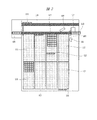
図1では、検体ラックの投入と収納を行うサンプラユニット100、サンプラユニットと各機能モジュールとの間で検体ラックを搬送するラック搬送ユニット200と、ラック搬送ユニット200に沿って配置されるベルト機構210、ラック搬送ユニット200との間で検体ラックの移載を行い、また一時的に検体ラックを待機させるバッファユニット300a,300b、バッファユニット300a,300b各々と対をなしバッファユニットの右側に配置される機能モジュール400a,400b、バッファユニット300aの左側に配置される付属モジュール450と管理用の操作部コンピュータ1,2で構成され、自動分析装置はネットワーク3により操作部コンピュータと接続されるシステムを例に示している。
In FIG. 1, a
次に図2を用いて、サンプラユニット100の構成を示す。
Next, the configuration of the
サンプラユニットは、検体ラックをシステム内に投入するための投入部101、検体ラックをシステムから回収するための収納部102、投入部からの検体ラックをラック搬送ユニット200に搬送する投入ラック移動ユニット103、検体ラックのIDを識別するためのID識別ユニット104、検体ラックに架設されている検体容器の高さ情報を検出するための検体容器高さ検出ユニット105、検体容器のIDを識別するためのID識別ユニット106、検体容器のIDを識別する際に検体容器を回転させるための回転機構ユニット107、ラック搬送ユニット200からのラックを収納部102まで移動するための収納ラック移動ユニット108、緊急検体ラックまたは、本システムより上流側に接続される検体搬送システムからラックを投入するための緊急検体投入部109、サンプラユニットからラック搬送ユニット200へのラック受渡し部110を備えている。
The sampler unit includes a
次に図3を用いて、バッファユニット300の構成を示す。 Next, the configuration of the buffer unit 300 will be described with reference to FIG.
バッファユニットは、検体ラックの搬入出時に検体ラックを一時的に待機できるラック搬入出待機部301、初回分析や再検分析のために一時的にバッファユニット内で検体ラックを保持するためのバッファ部302、精度管理検体を保持し、検体の蒸発防止のため保冷機構を備えた保冷部303、機能モジュールとのラック受渡しに使用されるモジュール搬入出待機部310、機能モジュールへの検体ラック搬送または、機能モジュールからの搬出ラックを搬送するためのラック搬送部311、バッファユニット300に直接検体ラックを投入できるラック投入部320、ラック投入部320より投入された検体ラックのIDおよび、検体ラックに架設される検体のIDを識別するためのID識別ユニット321、ラック搬送ユニット200に沿って配置されるベルト機構210との検体ラックの移載を行う検体ラック移載機構330、バッファ内の検体ラックを移動するための検体ラック移動機構340を備えている。
The buffer unit includes a rack loading / unloading
ラック搬送ユニット200による検体ラックの搬送処理は、操作部コンピュータ1よりの搬送指示により実施される。指定される搬送指示には、ラック受渡し部110からバッファユニット300への検体ラック搬送、ラック受渡し部110から直接回収、バッファユニット300から搬出された検体ラックを別のバッファユニット300へ搬送、バッファユニット300から搬出された検体ラックの回収および、システムのメンテナンス処理対応用にバッファユニット300から搬出された検体ラックの周回(最回帰)などがある。
The sample rack transport process by the
次に図4では、本システムに投入される検体ラックとして5本の検体容器を保持する例を示してあるが、保持可能な容器数はこれに限らず、1本以上であれば良く10本あるいはそれ以上のものでも使用可能である。1つ以上の検体容器502を保持するための支持体としての検体ラック500は、細長い箱状である。検体ラックには各検体ラックを識別するための情報(例えばバーコード、数字、文字など)を表示したラベル501が付されている。また検体容器502の外壁には、検体受付番号、患者名や年齢などの患者情報、検査項目名などを含む検体情報をバーコードなどにより表示した検体識別ラベル503が貼られている。
Next, FIG. 4 shows an example in which five sample containers are held as sample racks to be loaded into the system. However, the number of containers that can be held is not limited to this, and may be one or more. Or more than that can be used. A
次に図5を用いて、本システム内のサンプラユニット100および、ラック搬送ユニット200における検体ラックの投入搬送処理について説明する。なお、文末の番号は図5のフローチャートの処理ステップに対応する符号である。
Next, referring to FIG. 5, the sample rack loading / unloading process in the
本システムでは、投入部101に複数の検体ラックを架設した投入トレイ121を設置した後に操作部コンピュータ1でのユーザ指示により分析処理が開始される。しかし、ラック搬送ユニット200や、これに接続される複数のバッファユニット300や機能モジュールの装置状態全てが分析可能な状態に遷移する前に当該システムに対して検体ラックを投入することは許容しない。また、同時に当該システムに対して投入可能な検体ラックの数は、システムの構成や操作部コンピュータでの指定情報により異なるが一義的に規定されるため、投入済みの検体ラック数の総和を超えての追加投入は許容されない(ステップ601)。
In this system, analysis processing is started by a user instruction on the operation unit computer 1 after the
全ての装置が分析可能な状態に遷移した後、サンプラユニット100により投入トレイ121に架設される検体ラックは投入バッファ部122への移動が開始される。投入トレイ121に架設される検体ラックが全て投入バッファ部122に移動されると、投入トレイ121の交換が許諾されるようになるため、ユーザにより新たに検体ラックが架設された投入トレイ121が設置された場合は当該システムに対する検体ラックの追加投入に対応可能とする。
After all of the apparatuses have transitioned to a state in which analysis is possible, the sample rack installed on the
ラック投入バッファ部122に移動された検体ラックの検出を行う(ステップ603)。検体ラックが検出された場合は、投入ラック移動ユニット103により検体ラックを搬送し、ラックおよび、架設される検体のID情報を読み込み(ステップ604)、操作部コンピュータ1に対して当該ラックの搬送先を問い合わせる。問い合わせを受けた操作部コンピュータ1は、最適化された当該ラックの搬送先をラック搬送ユニット200に対して通知する。ラック搬送ユニット200は通知された検体ラックの搬送先指定により、当該ラックの搬送先を決定する(ステップ605)。
The sample rack moved to the rack
この時、緊急検体投入部109に設置された検体ラックを検出した場合は、前記緊急検体投入部109設置検体ラックの搬送動作を優先させる(ステップ602)。
At this time, when the sample rack installed in the emergency
ただし、先にラック投入バッファ部122より投入している検体ラックが群を形成する精度管理検体を保持した検体ラックまたは、キャリブレータ検体を保持した検体ラックである場合には群の形成ラックが継続する限りラック投入バッファ部122より投入を優先させる。
However, if the sample rack previously loaded from the rack
システム内に初めて供給される検体ラックの搬送先には、特定のバッファユニット300に隣接する機能モジュール400の場合と、読み込んだID情報が不定のために直接回収される搬送経路が指定される場合がある(ステップ606)。特定のバッファユニット300に搬送される場合には、搬入先となるバッファユニット300に対して検体ラックの搬送に使用するベルト機構210と、搬入すべきラックを特定可能なID情報をラック搬入準備要求として通知する(ステップ607)。これは、ラック搬送ユニット200がベルト機構210により当該ラックをバッファユニットへ搬送したときに、バッファユニットの検体ラック移載機構330を使用して、バッファユニット内に当該ラックを搬入するためである。
The transport destination of the sample rack supplied for the first time in the system is the case of the functional module 400 adjacent to the specific buffer unit 300 and the case where the transport path for direct collection is specified because the read ID information is indefinite. (Step 606). When transported to a specific buffer unit 300, the
搬入準備動作としてバッファユニット300の検体ラック移載機構330がベルト機構210上に移動されたことにより、バッファユニット300はラック搬送ユニット200に対して当該ラックの搬入準備が完了したことを報告する。ラック搬送ユニット200はバッファユニット300よりの搬入準備完了報告を受付ける(ステップ609)と、当該ラックの搬送対象となるバッファユニット300の検体ラック移載機構330位置までベルト機構210により検体ラックを搬送し、バッファユニット300にラックを搬入させる(ステップ610)。
As the sample
当該ラックを直接回収する場合も、バッファユニット300の検体ラック移載機構330を利用する(ステップ608)。この場合、システム上に接続される複数のバッファユニット300からどのバッファユニット300を選択するかは、装置の稼動状況を判断した上でラック搬送ユニット200により決定される。
Even when the rack is directly collected, the sample
次に図6を用いて、バッファユニット300から搬出された検体ラックを別の機能モジュール400により分析するために別のバッファユニット300に搬送するための検体ラックの搬送処理について説明する。 Next, a sample rack transport process for transporting the sample rack carried out from the buffer unit 300 to another buffer unit 300 for analysis by another functional module 400 will be described with reference to FIG.
一旦バッファユニット300に搬送された検体ラックは機能モジュール400による分析が施されるまで、バッファユニット300に保持されている。分析処理が完了したことにより、操作部コンピュータ1はラック搬送ユニット200および、バッファユニット300に対して当該ラックの搬送先を指示する。
The sample rack once transported to the buffer unit 300 is held in the buffer unit 300 until analysis by the functional module 400 is performed. When the analysis processing is completed, the operation unit computer 1 instructs the
バッファユニット300は当該ラックの搬出が可能な状態になると、当該ラックを特定可能なID情報と、搬出対象となる検体ラックを検出したことをラック搬送ユニット200に対して通知する。
When the buffer unit 300 is ready to be unloaded, the buffer unit 300 notifies the
ラック搬送ユニット200は、予め操作部コンピュータ1より通知された検体ラックの搬送指定情報とバッファユニット300より通知された当該ラックを特定可能なID情報により、バッファユニット300より搬出される検体ラックの搬送先を特定する(ステップ701)。この時に、合わせて検体ラックを搬送するために使用するベルト機構210を選別する。
The
ラック搬送ユニット200は、当該ラックの搬送先であるバッファユニット300の使用状況を判定して(ステップ702)、搬送可能と判断した場合には搬出元となるバッファユニット300に対して検体ラックの搬送に使用するベルト機構210と搬出すべきラックを特定可能なID情報をラック搬出準備要求として通知する。同時に搬入先となるバッファユニット300に対して検体ラックの搬送に使用するベルト機構210と搬入すべきラックを特定可能なID情報をラック搬入準備要求として通知する(ステップ703)。
The
検体ラックを搬出するバッファユニット300は搬出準備動作としてバッファユニット300の検体ラック移載機構330がベルト機構210上に移動されたことにより、ラック搬送ユニット200に対して当該ラックの搬出準備が完了したことを報告する(ステップ704)。また、検体ラックを搬入するバッファユニット300は搬入準備動作としてバッファユニット300の検体ラック移載機構330がベルト機構210上に移動されたことにより、ラック搬送ユニット200に対して当該ラックの搬入準備が完了したことを報告する(ステップ705)。
When the sample
ラック搬送ユニット200は搬出元バッファユニット300よりの搬出準備完了報告と搬入元バッファユニット300よりの搬入準備完了報告を受付けると、搬出元のバッファユニット300の検体ラック移載機構330位置より当該ラックの搬送対象となるバッファユニット300の検体ラック移載機構330位置までベルト機構210により検体ラックを搬送し、搬入先バッファユニット300に到着した検体ラックを搬入させる(ステップ706)。
When the
次に図7を用いて、バッファユニット300から搬出された検体ラックを回収搬送するための検体ラックの搬送処理について説明する。なお、収納部102は収納バッファ部132と収納部102に架設される収納トレイ131で構成される。収納トレイ131は回収された検体ラックを装置より取り出すためにユーザが架設して使用する。収納ラック移動ユニット108により収納部102前まで搬送されて来た回収検体ラックは、収納レバー133により収納バッファ部132に引き込まれる。この時、収納トレイ131が満杯でなければ更に収納レバー133により収納トレイ131まで移動される。
Next, a sample rack transport process for collecting and transporting the sample rack carried out from the buffer unit 300 will be described with reference to FIG. The
バッファユニット300内に存在する検体ラックに対する分析動作がすべて完了したと判断することにより、操作部コンピュータ1はラック搬送ユニット200および、バッファユニット300に対して当該ラックの回収搬送を指示する。
By determining that all the analysis operations for the sample racks existing in the buffer unit 300 have been completed, the operation unit computer 1 instructs the
バッファユニット300は当該ラックの搬出が可能な状態になると、当該ラックを特定可能なID情報と、搬出対象となる検体ラックを検出したことをラック搬送ユニット200に対して通知する。
When the buffer unit 300 is ready to be unloaded, the buffer unit 300 notifies the
ラック搬送ユニット200は、予め操作部コンピュータ1より通知された検体ラックの搬送指定情報とバッファユニット300より通知された当該ラックを特定可能なID情報により、バッファユニット300より搬出される検体ラックの搬送先を特定する(ステップ801)。この時に、合わせて検体ラックを搬送するために使用するベルト機構210を選別する。
The
ラック搬送ユニット200は、搬出元となるバッファユニット300に対して検体ラックの搬送に使用するベルト機構210と搬出すべきラックを特定可能なID情報をラック搬出準備要求として通知する(ステップ802)。
The
検体ラックを搬出するバッファユニット300は搬出準備動作としてバッファユニット300の検体ラック移載機構330がベルト機構210上に移動されたことにより、ラック搬送ユニット200に対して当該ラックの搬出準備が完了したことを報告する(ステップ803)。ラック搬送ユニット200は搬出元バッファユニット300よりの搬出準備完了報告を受付けると、搬出元のバッファユニット300の検体ラック移載機構330位置より収納ラック移動ユニット108受渡し位置までベルト機構210により検体ラックを搬送させる(ステップ804)。
When the sample
収納ラック移動ユニット108受渡し位置まで検体ラックを搬送したところで、収納部102上の回収済みラックを確認し(ステップ805)、収納部102が既に満杯でラック回収ができない状態であればユーザに対して収納部102に架設される収納トレイ131の交換を要求するアラームを出力する(ステップ806)。このアラーム出力は、収納トレイ131の交換が完了するまでの間周期的に出力される。収納トレイ131の交換により収納部102に検体ラックを収納可能な空きができたことで、収納部102への検体ラック回収が行われる(ステップ807)。
When the sample rack is transported to the delivery position of the storage
次に図8を用いて、バッファユニット300から搬出された検体ラックを周回搬送するための検体ラックの搬送処理について説明する。この検体ラック搬送はシステムのメンテナンス処理対応用に使用される搬送動作であり、収納ラック移動ユニット108により収納部102前まで搬送された検体ラックを収納レバー133により投入ラック移動ユニット103に移載して、再度システム内に搬送するものである。
Next, a sample rack transport process for circularly transporting the sample rack carried out from the buffer unit 300 will be described with reference to FIG. This sample rack transport is a transport operation used to deal with the maintenance process of the system. The sample rack transported to the front of the
バッファユニット300内に存在する検体ラックに対するメンテナンス動作がすべて完了したと判断することにより、操作部コンピュータ1はラック搬送ユニット200および、バッファユニット300に対して当該ラックの周回搬送を指示する。
When it is determined that all the maintenance operations for the sample racks existing in the buffer unit 300 have been completed, the operation unit computer 1 instructs the
バッファユニット300は当該ラックの搬出が可能な状態になると、当該ラックを特定可能なID情報と、搬出対象となる検体ラックを検出したことをラック搬送ユニット200に対して通知する。
When the buffer unit 300 is ready to be unloaded, the buffer unit 300 notifies the
ラック搬送ユニット200は、予め操作部コンピュータ1より通知された検体ラックの搬送指定情報とバッファユニット300より通知された当該ラックを特定可能なID情報により、バッファユニット300より搬出される検体ラックの搬送先を特定する(ステップ901)。この時に、合わせて検体ラックを搬送するために使用するベルト機構210を選別する。
The
ラック搬送ユニット200は、搬出元となるバッファユニット300に対して検体ラックの搬送に使用するベルト機構210と搬出すべきラックを特定可能なID情報をラック搬出準備要求として通知する(ステップ902)。
The
検体ラックを搬出するバッファユニット300は搬出準備動作としてバッファユニット300の検体ラック移載機構330がベルト機構210上に移動されたことにより、ラック搬送ユニット200に対して当該ラックの搬出準備が完了したことを報告する(ステップ903)。ラック搬送ユニット200は搬出元バッファユニット300よりの搬出準備完了報告を受付けると、搬出元のバッファユニット300の検体ラック移載機構330位置より収納ラック移動ユニット108受渡し位置までベルト機構210により検体ラックを搬送させる(ステップ904)。
When the sample
収納ラック移動ユニット108受渡し位置まで検体ラックを搬送したところで、投入ラック移動ユニット103上に検体ラックが存在しないことを確認し(ステップ905)、収納ラック移動ユニット108により収納部102前まで搬送された検体ラックを収納レバー133により投入ラック移動ユニット103に移載して搬送し、ラックおよび、架設される検体のID情報を読み込み(ステップ906)、操作部コンピュータ1に対して当該ラックの搬送先を問い合わせる。問い合わせを受けた操作部コンピュータ1は、メンテナンス動作のための当該ラックの搬送先をラック搬送ユニット200に対して通知する。ラック搬送ユニット200は通知された検体ラックの搬送先指定により、当該ラックの搬送先を決定する(ステップ907)。
When the sample rack has been transported to the delivery position of the storage
メンテナンス動作のため、搬送先はバッファユニット300となる。ラック搬送ユニット200は搬入先となるバッファユニット300に対して検体ラックの搬送に使用するベルト機構210と搬入すべきラックを特定可能なID情報をラック搬入準備要求として通知する(ステップ908)。
For the maintenance operation, the transport destination is the buffer unit 300. The
搬入準備動作としてバッファユニット300の検体ラック移載機構330がベルト機構210上に移動されたことにより、バッファユニット300はラック搬送ユニット200に対して当該ラックの搬入準備が完了したことを報告する。ラック搬送ユニット200はバッファユニット300よりの搬入準備完了報告を受付ける(ステップ909)と、当該ラックの搬送対象となるバッファユニット300の検体ラック移載機構330位置までベルト機構210により検体ラックを搬送し、バッファユニット300にラックを搬入させる(ステップ910)。
As the sample
前記ラック搬送ユニット200での検体ラックの搬送処理において、システム内に複数の検体ラックが搬入されている状態で検体ラックの供給動作が継続されている場合には、新たにシステム内に投入される検体ラックのバッファユニット300への検体ラック搬入動作要求と、同バッファユニット300からの検体ラック搬出動作要求などが重なることが起こる。 また、1つのベルト機構210上に複数の検体ラックが存在した状態で、同機構を動作させるとラック搬送ユニット200との間で搬入動作や搬出動作を行っているバッファユニット300の検体ラック移動機構340に検体ラックが干渉してしまう可能性がある。このような場合には、ラック搬送ユニット200は同機構上に対する資源管理を行い、1つの検体ラック搬送が開始される際に資源をロックし、搬送が完了した時点で資源を解放することで、複数の検体ラックが同時に存在しないように搬送処理を制御する搬送制御ロジックが採用されている。
In the sample rack transport process in the
ラック搬送ユニット200では、同ユニットに接続される複数のバッファユニット300間での検体ラック搬送を行う場合には、同ユニットの搬送動作に対する着手可能な状態を判別してから搬送動作に取り掛かるため、必ず同ユニットの搬送動作にバッファユニット300の搬入・搬出動作を同期させて搬送動作を行う搬送制御ロジックが採用されている。
In the
ラック搬送ユニット200では、同ユニットに接続される複数のバッファユニット300間での検体ラック搬送を行う場合には、搬出元のバッファユニット300と搬入先バッファユニット300とベルト機構210に対する資源確保が全て同期して制御されないと検体ラック搬送が成立しないため、何らかの理由により搬送条件が成立しない場合には、他に搬送可能な検体ラックが存在するかを判断し、搬送着手可能な検体ラックが検出された場合には、その検出されたラック搬送を先に実施することを可能とする搬送制御ロジックが採用されている。
In the
また、常に同じ搬送位置から搬送対象となる検体ラックの検出を実施していると、検体ラックの搬送になかなか着手されないケースが発生する。この搬送問題を回避するため、ラック搬送ユニット200には搬送着手位置の選択に優先順位を設けて、検体ラックの搬送に着手した搬送位置からの搬送処理着手は優先順位を下げる搬送制御ロジックが採用されていてもよい。
In addition, if detection of a sample rack to be transported is always performed from the same transport position, there may be a case where it is difficult to start transporting the sample rack. In order to avoid this transport problem, the
本実施例では、バッファユニット300による検体ラックの搬送処理は、操作部コンピュータ1よりの搬送指示により実施される。指定される搬送指示には、ラック搬送ユニット200から搬入された検体ラックに対しては、機能モジュール400への搬送、付属モジュール450への搬送、保冷部303への搬送、バッファ部302への搬送が指示される。また、機能モジュール400や付属モジュール450に搬送され分析を実施して同モジュールから搬出される検体ラックに対しては、隣接する別モジュール400または450への搬送、保冷部303への搬送、バッファ部302への搬送、別のバッファユニット300への搬送のためラック搬送ユニット200への搬出、回収のためラック搬送ユニット200への搬出、などが指示される。
In the present embodiment, the sample rack transport process by the buffer unit 300 is performed by a transport instruction from the operation unit computer 1. According to the designated transport instruction, for the sample rack loaded from the
次に図10を用いて、バッファユニット300から機能モジュール400や付属モジュール450への検体ラック搬入搬送処理について説明する。
Next, the sample rack carry-in / conveying process from the buffer unit 300 to the functional module 400 or the
機能モジュール400や付属モジュール450は、同モジュールが搬入可能な検体ラック数を規定している。既に、規定された検体ラック数が搬入してしまっているとバッファユニット300からの検体ラックは搬入できない。また、同モジュールが使用する試薬の不足など何らかの原因で使用できなくなるケースがあるため、バッファユニット300では同モジュールへの検体ラック搬送前に搬入が可能かどうかの判定処理を行う(ステップ1101)搬送制御ロジックが採用されている。
The function module 400 and the
既に機能モジュール400や付属モジュール450内に搬入可能な検体ラック数が搬入済みであれば、同モジュールから検体ラックが搬出されるまで搬入のための動作には着手しなければ良いが、何らかの理由により同モジュールが使用できなくなった場合には操作部コンピュータ1に対して指示された検体ラックの搬送ができないことを通知(ステップ1110)することで、同検体ラックの搬送指定先を問い合わせる制御ロジックが採用されている。
If the number of sample racks that can be loaded into the functional module 400 or the
バッファユニット300から機能モジュール400に検体ラックを搬入する場合、同モジュールに検体ラックを特定可能なID情報をラック搬入準備要求として通知する(ステップ1102)。 When the sample rack is loaded from the buffer unit 300 to the functional module 400, ID information that can identify the sample rack is notified to the module as a rack loading preparation request (step 1102).
機能モジュール400の検体ラック搬入準備が完了すると、同モジュールはバッファユニット300に対して搬入準備完了報告を通知してくるので、同ユニットはラック搬入出待機部301や保冷部303または、バッファ部302に待機してある検体ラックを検体ラック移動機構340によりモジュール搬入出待機部310まで運び、ラック搬送部311により同モジュールまで搬送して検体ラックの搬入動作を行う(ステップ1104)。
When the sample module loading preparation of the functional module 400 is completed, the module notifies the buffer unit 300 of a loading preparation completion report, so that the unit performs the rack loading /
バッファユニット300から付属モジュール450に検体ラックを搬入する場合は、同ユニットはラック搬入出待機部301や保冷部303または、バッファ部302に待機してある検体ラックを検体ラック移動機構340によりモジュール搬入出待機部310まで運び、同モジュールに直接搬入を行う。
When the sample rack is loaded from the buffer unit 300 to the
次に、バッファユニット内にある検体ラックを、隣接する機能モジュールへと搬入する場合の判断ロジックについて説明する。バッファユニットは、隣接する検体ラックを搬入しようとしている機能モジュール/付属モジュールが分析可能な状態であることを判断し、動作可能であれば当該機能モジュール/付属モジュールに対する検体ラックの搬入搬送動作に着手する。 Next, a description will be given of the determination logic when the sample rack in the buffer unit is carried into the adjacent functional module. The buffer unit determines that the function module / attached module to which the adjacent sample rack is to be loaded is ready for analysis, and if it is operable, starts the sample rack loading / unloading operation with respect to the function module / attached module. To do.
また、バッファユニットは、隣接する検体ラックを搬入しようとしている機能モジュール/付属モジュール内に検体ラックを保有可能な空きがあり、機能モジュール側の受け入れ準備が整っていること(機能モジュールに空きポジションがあること)を判断し、動作可能であれば当該機能モジュール/付属モジュールに対する検体ラックの搬入搬送動作に着手する。 In addition, the buffer unit has a space that can hold the sample rack in the function module / attached module to which the adjacent sample rack is to be loaded, and the function module is ready to accept (the function module has an empty position). If it is operable, the sample rack is carried in and carried out with respect to the functional module / attached module.
また、バッファユニットは、隣接する検体ラックを搬入しようとしている機能モジュール/付属モジュールへの検体ラック搬入動作以外の検体ラック搬入出搬送動作(たとえば既に機能モジュール/付属モジュールから搬出される検体ラックの受取りや、ラック搬送ユニットとの検体ラック搬入出搬送動作など)に着手していないことを判断し、動作可能であれば当該機能モジュール/付属モジュールに対する検体ラックの搬入搬送動作に着手する。 The buffer unit also performs a sample rack loading / unloading operation other than the sample rack loading / unloading operation to the functional module / attached module to which an adjacent sample rack is to be loaded (for example, receiving a sample rack already carried out from the functional module / attached module). Or the sample rack loading / unloading operation with the rack transport unit is not started, and if it is operable, the sample rack loading / unloading operation is started with respect to the functional module / attached module.
機能モジュール/付属モジュールでの処理が終了した検体ラックは、バッファユニットへ搬出される。バッファユニットが既に別の検体ラック搬送(検体ラック搬送ユニットとの搬入/搬出など)動作に着手していないことを確認し、動作可能であれば当該機能モジュール/付属モジュールからバッファユニットへ、検体ラックの搬出動作に着手する。 The sample rack that has been processed by the functional module / attached module is carried out to the buffer unit. Check that the buffer unit has not yet started another sample rack transport (loading / unloading with the sample rack transport unit, etc.), and if it is operable, transfer the sample rack from the function module / attached module to the buffer unit. Start the unloading operation.
次に図11を用いて、機能モジュール400や付属モジュール450からバッファユニット300へ搬出された検体ラックに対する搬送処理について説明する。
Next, with reference to FIG. 11, a transport process for the sample rack carried out from the functional module 400 or the attached
バッファユニット300は機能モジュール400や付属モジュール450から検体ラックを受取る際に同モジュールより搬出されるラックを特定可能なID情報を合わせて受取る。
When the buffer unit 300 receives a sample rack from the function module 400 or the attached
検体ラックの受取りが完了すると、操作部コンピュータ1に対して機能モジュール400や付属モジュール450から搬出されたラックを特定可能なID情報を通知し、検体ラックによる分析が完了したことを知らせることで、操作部コンピュータ1より同検体ラックの搬送先を取得する(ステップ1201)。
When the reception of the sample rack is completed, the operation unit computer 1 is notified of the ID information that can identify the rack carried out from the functional module 400 or the attached
バッファユニット300では前記の検体ラックがモジュール搬入出待機部310に留まる状態を回避するために、直に搬送指定先への検体ラック搬送ができないと判断した場合(ステップ1206,ステップ1211)は、一旦使用許諾を取得した保冷部303やバッファ部302に検体ラックを退避搬送して、目的の検体ラックが搬送指定先へ搬送できる状態に遷移した後に退避した検体ラックを搬送する搬送制御ロジックが採用されている(ステップ1207,ステップ1212)。
In the buffer unit 300, in order to avoid the state in which the sample rack stays in the module loading /
システム内に複数存在するバッファユニットに隣接する機能モジュールまたは付属モジュールでの分析が必要となった検体ラックが存在する時に、搬送先対象となるバッファユニット内のバッファ部に空きがなく搬送できないことが生じることがあり、これによりシステム全体の検体ラック搬送に支障がでる。 When there are sample racks that need to be analyzed by functional modules or accessory modules adjacent to multiple buffer units in the system, the buffer unit in the buffer unit to be transported may not be available for transport. This may hinder the transport of sample racks throughout the system.
このような場合には、搬送先対象となるバッファユニット内のバッファ部に待機している検体ラックのうち、再検査待ちなどでしばらく処理が実施されないと想定される検体ラックを一時的にバッファ部に空きがある別のバッファユニットに搬送し、それによりバッファユニット内にバッファ部の空きを作り、分析が必要な検体ラックを搬送可能とする。 In such a case, among the sample racks waiting in the buffer unit in the buffer unit to be transported, a sample rack that is assumed not to be processed for a while due to waiting for retesting is temporarily stored in the buffer unit. The sample is transported to another buffer unit having a space in the buffer unit, thereby creating a space in the buffer unit in the buffer unit so that a sample rack requiring analysis can be transported.
一時的に別のバッファユニットに移動された検体ラックは、当該バッファユニットにバッファ部が確保できる状態、または再検査実施を行う必要が生じたときに、一時的な退避の前に待機していたバッファユニットに対しての戻し搬送を行うことを可能とする。また、当該検体ラックを必要とする機能モジュールまたは付属モジュールが退避前のバッファユニットに隣接するものでない場合には、退避していたバッファユニットから当該検体ラックを必要とする機能モジュールまたは付属モジュールに隣接するバッファユニットに直接搬送することも可能とする。これによりバッファユニット内での保有ラック数検体ラックによる供給不可時間の短縮を図り、システム全体の処理能力向上に寄与する。 The sample rack that was temporarily moved to another buffer unit was in a standby state before being temporarily evacuated when the buffer unit could be secured in the buffer unit or when it was necessary to perform a retest. It is possible to perform return conveyance to the buffer unit. If the functional module or accessory module that requires the sample rack is not adjacent to the buffer unit before evacuation, it is adjacent to the functional module or accessory module that requires the sample rack from the evacuated buffer unit. It is also possible to transport directly to the buffer unit. As a result, the number of racks held in the buffer unit shortens the supply unavailable time due to the sample rack and contributes to the improvement of the processing capacity of the entire system.
もちろん、モジュール搬入出待機部310に搬出された検体ラックを直接搬送することが可能な場合には、操作部コンピュータ1よりの搬送指定先に従い(ステップ1202,ステップ1204,ステップ1205,ステップ1209)、検体ラックをバッファ部302や機能モジュール400などに対して搬送する(ステップ1203,ステップ1208,ステップ1214)。
Of course, when the sample rack carried out to the module loading /
操作部コンピュータ1から通知された検体ラックの搬送先が別のバッファユニット300や回収搬送の指示であった場合は、同ユニットからラック搬送ユニット200に対して搬出する検体ラックが検出された旨を、検体ラックを特定可能なID情報とともに通知する(ステップ1210)。
If the transport destination of the sample rack notified from the operation unit computer 1 is another buffer unit 300 or a recovery transport instruction, it indicates that a sample rack to be transported from the unit to the
また、バッファユニット300では操作部コンピュータ1より通知される搬送指定先に不定な搬送先が指定されてきた場合、搬送先指定異常アラームを出力し(ステップ1215)、操作部コンピュータ1に対して、当該検体ラックを回収するように促す処理も用意されている。 In addition, in the buffer unit 300, when an unspecified transport destination is designated as the transport designation destination notified from the operation unit computer 1, a transport destination designation abnormal alarm is output (step 1215), and the operation unit computer 1 is notified. A process for prompting the sample rack to be collected is also prepared.
次に図12を用いて、バッファユニット300からラック搬送ユニット200への検体ラック搬出搬送処理について説明する。
Next, the sample rack unloading / transporting process from the buffer unit 300 to the
バッファユニット300内に保持されている検体ラックは操作部コンピュータ1よりのラック搬出要求を受付ける(ステップ1301)ことで、搬出動作に着手される。 The sample rack held in the buffer unit 300 starts a carry-out operation by receiving a rack carry-out request from the operation unit computer 1 (step 1301).
バッファユニット300より搬出される検体ラックの搬送先は、別のバッファユニット300への搬送または、回収搬送が指定されるケースがある。 In some cases, the transport destination of the sample rack to be transported from the buffer unit 300 is designated as transport to another buffer unit 300 or collection transport.
本システムにおいて、バッファユニット300の保冷部303に搬送される精度管理検体を架設する検体ラックは、ラック搬送ユニット200からの搬入時に保冷部303内の使用許諾されていないスロット位置に割り付けられ、本システム上から回収されるまでの間、一度割り付けられた保冷部303のスロット位置で運用される。別のバッファユニット300で分析されるために搬出される場合(ステップ1303)は、保冷部303内の使用許諾を開放しない。回収のための搬出である場合(ステップ1303)は、保冷部303内の使用許諾を開放する(ステップ1304)。これにより、保冷部で待機する必要のあるこれらの検体ラックについては、システム内に複数存在するバッファユニットに隣接される分析ユニットで必要となった場合に、バッファユニット毎に待機場所を確保しないで運用することが可能となる。これによって、システム内に投入する精度管理検体の数を削減することが可能である。また、精度管理検体がシステム内に待機しているため、品質管理の簡略確認、および精度管理検体の有効使用期限の判断が容易となる。
In this system, the sample rack for laying the quality control sample transported to the
本システムにおいて、バッファユニット300のバッファ部302に搬送される検体ラックは、ラック搬送ユニット200からの搬入時にバッファ部302内の使用許諾されていないスロット位置に割り付けられ、ラック搬送ユニット200に搬出されるまでの間、一度割り付けられたバッファ部302のスロット位置で運用されるため、別のバッファユニット300で分析されるための搬出である場合でも回収のための搬出である場合でもバッファ部302内の使用許諾を開放する(ステップ1305)。
In this system, the sample rack transported to the
バッファユニット300で管理される保冷部303とバッファ部302の使用許諾は一度開放されると、次に搬入されてきた検体ラックにより使用することが可能となる。
Once the use permission of the
バッファユニット300は、同ユニットから搬出搬送される検体ラックを検出するとラック搬送ユニット200に対して検体ラックを特定可能なID情報とともに搬出ラック検出を通知する(ステップ1306)。
When the buffer unit 300 detects the sample rack carried out and transported from the unit, the buffer unit 300 notifies the
ラック搬送ユニット200はバッファユニット300から通知された搬出する検体ラックの検出通知に対しての搬出動作に対応可能となると、バッファユニット300に対して当該ラックを搬出すべきベルト機構210の情報とともに搬出準備要求を通知する。
When the
バッファユニット300はラック搬送ユニット200よりの搬出準備要求により、バッファユニット300の検体ラック移載機構330を使用して当該ラックを搬出搬送に使用するベルト機構210上に移動させて検体ラックの搬出を行う(ステップ1308)。
In response to a carry-out preparation request from the
前記バッファユニット300での検体ラックの搬送処理において、バッファユニット300内に搬送された検体ラックには優先度(ex.緊急ラック>一般ラック>洗浄ラック)が設けられ、その優先度が高いものを優先して搬送しなければならないルールがある。そのため、搬送する検体ラックの種別や指定される優先順位に基づきラック搬送に着手する搬送制御ロジックが採用されている。 In the sample rack transport process in the buffer unit 300, the sample rack transported in the buffer unit 300 is provided with a priority (ex. Emergency rack> general rack> washing rack), and the one with the highest priority is provided. There are rules that must be preferentially transported. Therefore, a transport control logic that starts rack transport based on the type of sample rack to be transported and the specified priority order is employed.
また、着手してしまった群(機能モジュール400や付属モジュール450に搬送されてしまったラックと同一の群を形成するラック)は、追い越してはならないルールがある。そのため、群管理を意識してラック搬送に着手する搬送制御ロジックが採用されている。 Further, there is a rule that a group that has started (a rack that forms the same group as a rack that has been transported to the functional module 400 or the accessory module 450) must not be overtaken. Therefore, a transport control logic that starts rack transport in consideration of group management is employed.
バッファユニット300での検体ラックの搬送処理において、バッファユニット300内に搬入された検体ラックの搬送や機能モジュール400から搬出された検体ラックの搬送動作要求が重なることが起こる。 In the sample rack transport process in the buffer unit 300, transport of sample racks carried into the buffer unit 300 and transport operation requests for sample racks transported out from the functional module 400 may overlap.
また、常に同じ搬送位置から搬送対象となる検体ラックの検出を実施していると、検体ラックの搬送になかなか着手されないケースが発生する。 In addition, if detection of a sample rack to be transported is always performed from the same transport position, there may be a case where it is difficult to start transporting the sample rack.
前記の搬送問題を回避するため、バッファユニット300には搬送着手位置の選択に優先順位を設けて、検体ラックの搬送に着手した搬送位置からの搬送処理着手は優先順位を下げる搬送制御ロジックが採用されている。 In order to avoid the above-mentioned transport problem, a priority is given to the selection of the transport start position in the buffer unit 300, and the transport control logic that lowers the priority is adopted for the transport processing start from the transport position where the transport of the sample rack is started. Has been.
バッファユニット300では搬送ユニット200との検体ラック搬入出や機能モジュール400との検体ラック搬入出および、付属モジュール450との検体ラック搬入出が必要であり、複数の搬送処理要求を同時に受付けられる。
The buffer unit 300 requires sample rack loading / unloading with the
上記、複数の搬送経路に対する実際の検体ラック搬送ではランダムに発生する検体ラック搬送要求の検出順序を動的に変更する。つまり、実際の搬送動作を実施した経路の搬送要求検出順序は最後尾の検出対象に位置づけられ、まだ着手されていない検体ラックに対する搬送要求の検出が優先的に検出される制御ロジックが採用されている。 In the above-described actual sample rack transport for a plurality of transport paths, the detection order of the sample rack transport requests that are randomly generated is dynamically changed. In other words, the transport request detection order of the path in which the actual transport operation has been performed is positioned as the last detection target, and the control logic that preferentially detects the transport request for the sample rack that has not been started yet is adopted. Yes.
バッファユニット300の保冷部303は精度管理検体を保持し、検体の蒸発防止のため保冷機構を備えているために、外気と触れることで保冷部303に保持される検体ラックに架設される精度管理検体に影響がでる。これを回避する目的で、保冷部303への検体ラック搬入や保冷部303からの検体ラック搬出時には検体ラックアクセスに必要な分だけのドアの開閉を行う機構制御ロジックが採用されている。
The
ラック搬送ユニット200が故障した時などの対応としてバッファユニット300にはバックアップオペレーション機能が提供される。これは、バッファユニット300に直接検体ラックを投入できるラック投入部320から投入し、投入された検体ラックのIDおよび、検体ラックに架設される検体のIDを識別するためのID識別ユニット321のよりラックおよび、架設される検体のID情報を読み込み当該ラックの分析を行える機能である。
The buffer unit 300 is provided with a backup operation function as a countermeasure when the
バッファユニット内にある検体ラックを、検体ラック搬送ユニットへ搬出する場合の判断ロジックについて説明する。搬出予定の検体ラックを有するバッファユニットは、検体ラック搬送ユニットが既に別のバッファユニットとの間で検体ラック搬送動作に着手していないことを判断し、動作可能であれば当該バッファユニットからの検体ラックの搬出搬送動作に着手する。 The determination logic when the sample rack in the buffer unit is carried out to the sample rack transport unit will be described. The buffer unit having the sample rack to be carried out is determined that the sample rack transport unit has not yet started the sample rack transport operation with another buffer unit, and if it is operable, the sample from the buffer unit The rack unloading and transporting operation is started.
また、バッファユニットは、既に別の検体ラック搬送(機能モジュールとの搬入/搬出など)動作に着手していないことを判断し、動作可能であれば搬送ユニット検体ラックの搬出動作に着手する。 Further, the buffer unit determines that another sample rack transport operation (such as loading / unloading with a functional module) has not been started, and starts a transport unit sample rack transport operation if it is operable.
次に図9を用いて、ラック搬送ユニット200からバッファユニット300への検体ラック搬入搬送処理について説明する。
Next, with reference to FIG. 9, the sample rack carrying and transporting process from the
バッファユニット300はラック搬送ユニット200からのラック搬入準備要求により通知される検体ラックの搬送に使用するベルト機構210と搬入すべきラックを特定可能なID情報を知ることができる。検体ラック移載機構330を搬入対象となるベルト機構210位置まで移動して、ラック搬送ユニット200から搬送されてくる検体ラックを受取る。
The buffer unit 300 can know ID information that can identify the
検体ラックの受取りが完了すると、操作部コンピュータ1に対して搬入したラックを特定可能なID情報を通知し、検体ラックが到着したことを知らせる(ステップ1001)。 When the reception of the sample rack is completed, the operation unit computer 1 is notified of ID information that can identify the rack that has been loaded, and notifies the arrival of the sample rack (step 1001).
操作部コンピュータ1はバッファユニット300から通知されたID情報により、バッファユニット300に搬入された検体ラックの搬送先を同ユニットに通知する。 Based on the ID information notified from the buffer unit 300, the operation unit computer 1 notifies the unit of the transport destination of the sample rack carried into the buffer unit 300.
バッファユニット300は操作部コンピュータ1により指定された検体ラックの搬送先指定により到着した検体ラックの搬送を行う前に、バッファユニット300では搬送指定先を判別(ステップ1002,1005,1007,1008)することにより同ユニット内の保冷部303または、バッファ部302に存在する空きスロット位置に対して使用許諾を取得する(ステップ1003,1004)。
The buffer unit 300 discriminates the designated transfer destination in the buffer unit 300 (
前記、空きスロット位置に対しての使用許諾を取得する目的は、例えば搬入されてきた検体ラックの搬送指定先が機能モジュール400であった場合、既に搬送先の機能モジュール内に同モジュールが搬入可能な検体ラック数を既に搬入してしまっていると、搬送できないケースが発生する。これによりバッファユニット300に搬入された検体ラックがラック搬入出待機部301に留まると、バッファユニット300から別の検体ラックをラック搬送ユニット200に搬出できなくなるので、これを回避するためである。
The purpose of obtaining the use permission for the empty slot position is, for example, when the transport designation destination of the loaded sample rack is the function module 400, the same module can be already loaded into the function module of the transport destination. If a large number of sample racks have already been loaded, there may be cases where the sample rack cannot be transported. As a result, if the sample rack carried into the buffer unit 300 remains in the rack carry-in / out waiting
バッファユニット300では前記の検体ラックがラック搬入出待機部301に留まる状態を回避するために、搬送指定先の機能モジュール400や付属モジュール450が検体ラックを投入できない状態であると判定した場合、一旦使用許諾を取得した保冷部303やバッファ部302に検体ラックを退避搬送(ステップ1010)してラック搬入出待機部301を開放し、機能モジュール400や付属モジュール450が検体ラックを投入可能な状態に遷移した後に退避した検体ラックを搬送する搬送制御ロジックが採用されている。
In the buffer unit 300, in order to avoid the state in which the sample rack stays in the rack loading /
もちろん、ラック搬入出待機部301に搬入した検体ラックを直接搬送することが可能な場合には、操作部コンピュータ1よりの搬送指定先に従い、検体ラックをバッファ部302や機能モジュール400や付属モジュール450に対して搬送する(ステップ1006,1009)。
Of course, when the sample rack loaded into the rack loading /
検体ラック搬送ユニットで搬送された検体ラックを、バッファユニットへ搬入する場合の判断ロジックについて説明する。検体ラック搬送ユニットは、これから検体ラックを搬入する予定のバッファユニットが、隣接する機能モジュールや検体ラック搬送ユニットとの間で既に別の検体ラック搬送(搬入/搬出)動作に着手していないことを確認し、動作可能であれば当該バッファユニットに対する検体ラックの搬入/搬送動作に着手する。 The determination logic when the sample rack transported by the sample rack transport unit is transported to the buffer unit will be described. The sample rack transport unit confirms that the buffer unit scheduled to carry in the sample rack has not yet started another sample rack transport (loading / unloading) operation with the adjacent functional module or sample rack transport unit. Confirm and if possible, start the sample rack loading / conveying operation for the buffer unit.
また、検体ラック搬送ユニットは、検体ラックを搬入しようとするバッファユニット内に新たな検体ラックを保持可能なバッファ部の空きがあることを確認し、動作可能であれば当該バッファユニットに対する検体ラックの搬入搬送動作に着手する。 In addition, the sample rack transport unit confirms that there is an available buffer section that can hold a new sample rack in the buffer unit to which the sample rack is to be loaded, and if it is operable, the sample rack transport unit Initiate the carry-in operation.
操作部コンピュータは、検体ラック搬送ユニットが検体ラックを搬入しようとするバッファユニット内に、新たな検体ラックを保持可能なバッファ部の空きがない場合には、システム内にある他のバッファユニットに対して、検体ラックを搬入しようとするバッファユニット内にある他の検体ラックを一時的に保持可能なバッファの空きを有するものがあるか検索する。退避させた検体ラックを保持可能なバッファユニットが他に見つかった場合には、検体ラック搬送ユニット・退避させる検体ラックを保有するバッファユニット、および、退避先となるバッファユニットに対して検体ラックの退避動作を指示する。 If there is no available buffer unit that can hold a new sample rack in the buffer unit to which the sample rack transport unit is to carry the sample rack, the operation unit computer will not be able to use other buffer units in the system. Thus, a search is made as to whether there is an available buffer that can temporarily hold another sample rack in the buffer unit to which the sample rack is to be loaded. When another buffer unit that can hold the evacuated sample rack is found, the sample rack is evacuated from the sample rack transport unit, the buffer unit that holds the sample rack to be evacuated, and the buffer unit that is the evacuation destination. Instruct the operation.
また、バッファユニット300では操作部コンピュータ1より通知される搬送指定先に不定な搬送先が指定されてきた場合、搬送先指定異常アラームを出力し(ステップ1011)、操作部コンピュータ1に対して、当該検体ラックを回収するように促す処理も用意されている。 In addition, in the buffer unit 300, when an indefinite transport destination is designated as the transport designation destination notified from the operation unit computer 1, a transport destination designation abnormal alarm is output (step 1011), and the operation unit computer 1 is notified. A process for prompting the sample rack to be collected is also prepared.
これらの搬送動作は、全ての動作結果が操作部コンピュータ1の外部記憶装置に記憶されており、この動作結果を表示するためのログ情報出力機能を持っている。このため、オペレータは特定の検体がいつ、どの場所に移動したのかを追跡することが出来る。 In these transport operations, all operation results are stored in the external storage device of the operation unit computer 1 and have a log information output function for displaying the operation results. For this reason, the operator can track when and where a specific specimen has moved.
また、システム内に投入される検体ラックに搭載された検体は、当該システムを構成する複数の機能モジュールまたは付属モジュールにより分析される場合がある。このような場合に、搬送する全ての機能モジュールまたは付属モジュールでの処理時間よる負荷を考慮しないで搬送すると、システム全体での処理能力に影響を及ぼす恐れがある。 In addition, a sample mounted on a sample rack that is input into the system may be analyzed by a plurality of functional modules or accessory modules that constitute the system. In such a case, if the transfer is performed without considering the load due to the processing time in all the function modules or accessory modules to be transferred, the processing capability of the entire system may be affected.
また、常にシステム内への検体ラック投入位置から近い機能モジュールまたは付属モジュールへの搬送から行うと、検体ラックの保有数が多く搬送動作に負荷が掛かるバッファユニットと検体ラックがなかなか到着しないで搬送動作に負荷が掛からないバッファユニットができてしまい、システム全体での処理能力に影響を及ぼすこともある。 In addition, when transporting to a functional module or an accessory module that is always close to the sample rack loading position in the system, the transport operation is performed without the arrival of the buffer units and sample racks that have a large number of sample racks and place a load on the transport operation. In some cases, a buffer unit that is not loaded is created, which affects the processing capability of the entire system.
このような場合には、検体ラック投入時点において、機能モジュールまたは付属モジュールに割り当てられている処理依頼数や、その機能モジュール等での処理時間などから求まる負荷率に基づいて、システム内に投入される検体ラックの搬送先モジュールを選択する。 In such a case, when the sample rack is loaded, the sample is loaded into the system based on the number of processing requests assigned to the function module or attached module and the load factor obtained from the processing time in the function module. Select the destination rack transport module.
このような搬送処理を提供することで、システム内の機能モジュール等での分析空き時間を短縮することができ、システム全体の処理能力向上に寄与する。また、機能モジュール等の処理完了時に次の搬送先を決定することにより、検体ラック投入時には分析を行う予定であった機能モジュールまたは付属モジュールが何らかの要因で使用できなくなった場合などでも、それらを回避したラック搬送を実施できるラック搬送を実現することができる。 By providing such a conveyance process, it is possible to reduce the analysis idle time in the function modules in the system, which contributes to the improvement of the processing capacity of the entire system. In addition, by determining the next transport destination when processing of a functional module, etc. is completed, even if the functional module or accessory module that was scheduled to be analyzed at the time of sample rack insertion becomes unavailable for some reason, it is avoided Rack transportation that can carry out the rack transportation can be realized.
また、これらのフローの判断は操作部コンピュータが統括して判断しても良いし、各ユニットが状況に応じて個々に判断しても良い。 The determination of these flows may be made by the operation unit computer in an integrated manner, or each unit may make an individual determination according to the situation.
1 操作部コンピュータ
2 操作部CRT(情報表示部)
3 ネットワーク接続
100 サンプラユニット
101 投入部
102 収納部
103 投入ラック移動ユニット
104 ラックID識別ユニット
105 検体容器高さ検出ユニット
106 検体ID識別ユニット
107 検体容器回転ユニット
108 収納ラック移動ユニット
109 緊急検体投入部
121 投入トレイ
122 投入バッファ部
123 投入レバー
131 収納トレイ
132 収納バッファ部
133 収納レバー
200 ラック搬送ユニット
201 送りレーン
202 戻りレーン
210 ベルト機構
300a,300b バッファユニット
301 ラック搬入出待機部
302 バッファ部
303 保冷部
310 モジュール搬入出待機部
311 ラック搬送部
320 1ラック投入取り出し部(1ラック投入部)
321 ID識別ユニット
330 ラック移載機構
350 モジュール搬入出待機位置
360 ラック移動機構
400a,400b 機能モジュール
450 付属モジュール
500 検体ラック
501 検体ラックID
502 検体容器
503 検体ID
601 ラック投入可/不可判定ステップ
602 緊急検体投入部搬入ラック検出判定ステップ
603 検体投入部搬入ラック検出判定ステップ
604 投入ラックID読取りステップ
605 投入ラック搬送先決定ステップ
606 投入ラック搬送先指定判定ステップ
607 バッファユニット搬入準備要求通知ステップ
608 投入ラック回収動作実施ステップ
609,705,909 バッファユニット搬入準備完了判定ステップ
610,706,910 バッファユニットへのラック搬入動作実施ステップ
701 バッファユニット搬出ラック検出判定ステップ
702 搬送先バッファユニット搬入許可判定ステップ
703 バッファユニット搬入/搬出準備要求通知ステップ
704 バッファユニット搬出準備完了判定ステップ
801 バッファユニット回収搬出ラック検出判定ステップ
802,902 バッファユニット搬出準備要求通知ステップ
803,903 バッファユニット搬出準備完了判定ステップ
804 回収ラック搬送動作実施ステップ
805 ラック収納部状態判定ステップ
806 ラック収納部満杯検知アラーム出力ステップ
807 収納部へのラック回収動作実施ステップ
901 バッファユニット周回搬出ラック検出判定ステップ
904 周回ラック搬送動作実施ステップ
905 ラック投入可/不可判定
906 投入ラックID読取りステップ
907 投入ラック搬送先決定ステップ
1001 バッファユニットへのラック到着ステップ
1002,1202 保冷部へのラック搬送判定ステップ
1003 保冷部の使用許諾取得ステップ
1004 バッファ部の使用許諾取得ステップ
1005,1204 バッファ待機判定ステップ
1006 バッファ部への搬送動作実施ステップ
1007 機能モジュール/付属モジュール搬送判定ステップ
1008,1206 機能モジュール/付属モジュール搬入許可判定ステップ
1009,1208 機能モジュール/付属モジュール搬送動作実施ステップ
1010,1207,1212 バッファ部への退避搬送動作実施ステップ
1011 搬送先不定アラーム出力ステップ
1101 機能モジュール/付属モジュール搬入判定ステップ
1102 機能モジュール/付属モジュール搬出準備要求通知ステップ
1103 機能モジュール/付属モジュール搬出準備完了判定ステップ
1104 機能モジュール/付属モジュール搬入動作ステップ
1201 機能モジュール/付属モジュールからの搬出ラック受け取りステップ
1203 待機位置へのラック搬送動作実施ステップ
1205 機能モジュール/付属モジュールへのラック搬送先判定ステップ
1209 別のバッファユニットへのラック搬送先判定ステップ
1210 ラック搬送ユニットへの搬出ラック検知報告ステップ
1211,1307 ラック搬送ユニットからの搬出準備要求判定ステップ
1213,1305 バッファ部の使用許諾開放ステップ
1214 バッファユニットからのラック搬出動作実施ステップ
1215 搬送先不定アラーム出力ステップ
1301 ラック搬出要求判定ステップ
1302 搬出ラックの待機部判定ステップ
1303 搬出ラックの搬送先判定ステップ
1304 保冷部の使用許諾開放ステップ
1306 ラック搬送ユニットへの搬出ラック検知報告ステップ
1308 バッファユニットからのラック搬出動作実施ステップ1
3
321
502
601 Rack loading enable / disable determination step 602 Emergency sample loading unit loading rack detection determination step 603 Sample loading unit loading rack detection determination step 604 Loading rack ID reading step 605 Loading rack transport destination determination step 606 Loading rack transport destination designation determination step 607 Buffer Unit loading preparation request notification step 608 Input rack collection operation execution steps 609, 705, 909 Buffer unit loading preparation completion determination steps 610, 706, 910 Buffer unit rack loading operation execution step 701 Buffer unit unloading rack detection determination step 702 Transport destination Buffer unit loading permission determination step 703 Buffer unit loading / unloading preparation request notification step 704 Buffer unit loading preparation completion determination step 801 Buffer unit Recovery carry-out rack detection determination steps 802 and 902 Buffer unit carry-out preparation request notification steps 803 and 903 Buffer unit carry-out preparation completion determination step 804 Recovery rack transport operation execution step 805 Rack storage unit state determination step 806 Rack storage unit full detection alarm output step 807 Step 901 for carrying out rack collection into the storage unit Step 901 for detecting the unwrapping rack around the buffer unit Step 904 for carrying out the round rack carrying operation 905 Determining whether the rack can be loaded / not permitted 906 Loading rack ID reading step 907 Loading rack transport destination determining step 1001 Rack arrival steps 1002 and 1202 Rack conveyance determination step 1003 for cold storage unit Usage permission acquisition step 1004 for buffer storage unit Usage permission acquisition step 1 for buffer unit 05, 1204 Buffer standby determination step 1006 Transfer operation to buffer unit execution step 1007 Function module / accessory module transfer determination step 1008, 1206 Function module / accessory module transfer permission determination step 1009, 1208 Function module / accessory module transfer operation execution step 1010 , 1207, 1212 Execution of evacuation and transfer operation to buffer unit Step 1011 Output destination undefined alarm output step 1101 Function module / attached module carry-in determination step 1102 Function module / attached module carry-out preparation request notification step 1103 Function module / attached module carry-out preparation completion determination Step 1104 Function module / attached module import operation step 1201 Unloading rack from function module / attached module Step 1203 for rack transport operation to stand-by position 1205 Step for determining rack transport destination to function module / attached module 1209 Step for determining rack transport destination to another buffer unit 1210 Step for reporting rack detection to rack transport unit 1211 , 1307 Unloading preparation request judgment step 1213 from the rack transport unit 1305 1305 Buffer unit license release step 1214 Rack unloading operation execution step 1215 Buffer unit undefined alarm output step 1301 Rack unloading request determination step 1302 Unloading rack standby Part determination step 1303 Transport destination determination step 1304 for unloading rack Release permission for use of cooling unit 1306 Unloading rack detection report step 13 to rack transport unit 08 Steps to carry out rack unloading operation from buffer unit
Claims (14)
検体を投入する投入部と検体を収納する収納部を有するサンプラユニットと、
前記投入部から投入された検体を前記分析セットに搬送する第一のベルトレーン機構と、前記分析セットから前記収納部に検体を搬送する第二のベルトレーン機構を有するラック搬送ユニットと、
を備えた自動分析システムにおいて、
前記サンプラユニットは、前記ラック搬送ユニット内の検体ラックのIDを読み込んで識別するラックID識別手段を有し、
前記バッファユニットは、
検体ラックを、前記ラック搬送ユニットから前記バッファ部又は前記ラック搬送部のいずれかに双方向に移載することが可能なラック移載機構を備え、
前記複数組の分析セットのすべてのバッファユニットの動作状況および依頼された分析項目に基づいて、前記投入部に投入された検体ラックの搬送先および搬送タイミングを制御するように、前記ラック搬送ユニットの動作を制御する制御手段を備え、
前記制御手段は、
前記投入部から投入された検体ラックが、前記ラックID識別手段によって読み込まれたID情報が不定であることにより回収すべき検体ラックである場合には、前記第一のベルトレーン機構を経由して前記ラック移載機構に到達した検体ラックを、前記バッファ部を経由させずに直接前記第二のベルトレーン機構上へ移載するよう前記ラック移載機構を制御することを特徴とする自動分析システム。 A module that executes analysis of a sample including analysis, a buffer unit that is provided in a pair with the module, is disposed upstream of the module, and includes a buffer unit that can wait for the sample; and the buffer unit A plurality of analysis sets having a rack transport unit that transports a sample rack carrying a sample between the modules; and
A sampler unit having an input unit for inputting a sample and a storage unit for storing the sample;
A rack transport unit having a first belt lane mechanism for transporting a sample input from the input unit to the analysis set, and a second belt lane mechanism for transporting a sample from the analysis set to the storage unit;
In the automatic analysis system with
The sampler unit has rack ID identifying means for reading and identifying the sample rack ID in the rack transport unit;
The buffer unit is
A rack transfer mechanism capable of bidirectionally transferring the sample rack from the rack transfer unit to either the buffer unit or the rack transfer unit;
Based on the operation status of all the buffer units of the plurality of analysis sets and the requested analysis items, the rack transport unit of the rack transport unit is controlled so as to control the transport destination and transport timing of the sample rack loaded in the input unit. Comprising control means for controlling the operation;
The control means includes
When the sample rack loaded from the loading unit is a sample rack to be collected because the ID information read by the rack ID identifying means is indefinite, the sample rack is routed through the first belt lane mechanism. An automatic analysis system that controls the rack transfer mechanism to transfer the sample rack that has reached the rack transfer mechanism directly onto the second belt lane mechanism without passing through the buffer unit. .
前記制御手段は、The control means includes
前記複数組の分析セットのすべてのバッファユニットの動作状況および依頼された分析項目に基づいて、前記複数組の分析セットにおける前記バッファユニットのうち、いずれのバッファユニットにおける前記ラック移載機構を利用するかを選択し、当該選択されたラック移載機構を制御することにより、前記ラック移載機構に到達した検体ラックを、前記バッファ部を経由させずに直接前記第二のベルトレーン機構上へ移載することを特徴とする自動分析システム。Based on the operation status of all the buffer units of the plurality of analysis sets and requested analysis items, the rack transfer mechanism in any buffer unit among the buffer units in the plurality of analysis sets is used. By controlling the selected rack transfer mechanism, the sample rack that has reached the rack transfer mechanism is directly transferred onto the second belt lane mechanism without passing through the buffer unit. An automatic analysis system characterized by
前記制御手段は、前記バッファユニットに到達した検体ラックが当該バッファユニットと対に設けられた前記モジュールに投入不可である場合には、前記ラック搬送ユニットを経由して前記ラック移載機構に到達した検体ラックを、前記バッファ部に移載するようラック移載機構を制御することを特徴とする自動分析システム。 In claim 1 Symbol placement automated analysis system,
The control means reaches the rack transfer mechanism via the rack transport unit when the sample rack that reaches the buffer unit cannot be put into the module provided in a pair with the buffer unit. An automatic analysis system characterized by controlling a rack transfer mechanism to transfer a sample rack to the buffer unit.
前記制御手段は、前記モジュールから前記ラック搬送部を経由して搬出され前記ラック移載機構に到達した検体ラックが、前記ラック搬送ユニットにて受渡し可能である場合には、当該検体ラックを前記バッファ部を経由させずに、直接前記ラック搬送ユニットに移載するようラック移載機構を制御することを特徴とする自動分析システム。 In claim 1 Symbol placement automated analysis system,
When the sample rack that has been unloaded from the module via the rack transport unit and has reached the rack transfer mechanism can be delivered by the rack transport unit, the control means transfers the sample rack to the buffer. An automatic analysis system characterized by controlling a rack transfer mechanism so as to transfer directly to the rack transport unit without passing through a section.
前記制御手段は、前記モジュールから前記ラック搬送部を経由して搬出され前記ラック移載機構に到達した検体ラックが、前記ラック搬送ユニットに受渡し不可である場合には、当該検体ラックを前記バッファ部に移載するようラック移載機構を制御することを特徴とする自動分析システム。 The automatic analysis system according to claim 1,
When the sample rack unloaded from the module via the rack transport unit and reaching the rack transfer mechanism cannot be delivered to the rack transport unit, the control means moves the sample rack to the buffer unit. An automatic analysis system characterized by controlling a rack transfer mechanism so as to be transferred to a machine.
前記バッファユニットは前記対となるモジュールとは別のモジュールが接続可能であり、
前記制御手段は、前記ラック搬送ユニットを経由して前記バッファユニットに到達した検体ラックを、前記バッファ部を経由させずに、当該バッファユニットと接続された複数のモジュールのうち、搬入可能であるモジュールに対して直接移載するようラック移載機構を制御することを特徴とする自動分析システム。 In claim 1 Symbol placement automated analysis system,
The buffer unit is a separate module and makes the chromophore at the distal end Joule such as the pair can be connected,
The control means, the sample rack has reached the buffer unit via the rack transport unit, without passing through the buffer unit, among the plurality of modules connected with the buffer unit, carrying possible der automated analysis system and controls the rack transfer mechanism to transfer directly to makes the chromophore at the distal end joules.
前記ラックID識別手段は、前記ラック搬送ユニット内の検体ラックのIDを読み込んで操作部コンピュータに通知し、
前記制御手段は、前記操作部コンピュータが、通知されたID情報に基づいて最適化された当該検体ラックの搬送先に関する情報を指示すると、搬送先の分析セットに含まれる前記バッファユニットの搬入準備が完了したか否かに基づいて当該検体ラックの搬送処理を制御することを特徴とする自動分析システム。 In claim 1 Symbol placement automated analysis system,
The rack ID identifying means reads the ID of the sample rack in the rack transport unit and notifies the operation unit computer,
When the operation unit computer instructs the information related to the transport destination of the sample rack optimized based on the notified ID information, the control unit prepares for loading of the buffer unit included in the analysis set of the transport destination. An automatic analysis system characterized in that the transport processing of the sample rack is controlled based on whether or not it is completed.
前記制御手段は、操作部コンピュータからの搬送指示により前記検体ラックをバッファユニットに搬送することを特徴とする自動分析システム。 The automatic analysis system according to claim 7,
The automatic analysis system, wherein the control means transports the sample rack to a buffer unit in accordance with a transport instruction from an operation unit computer.
前記制御手段は、前記複数のバッファユニットのうち搬入可能な前記バッファユニットに対して、搬送すべき検体ラックをバッファユニットに搬送するよう制御することを特徴とする自動分析システム。 The automatic analysis system according to claim 7,
The said control means controls the sample rack which should be conveyed with respect to the said buffer unit which can be carried in among these buffer units so that a sample rack may be conveyed to a buffer unit.
前記制御手段は、前記複数のバッファユニットのうち搬出可能な前記バッファユニットから回収すべき検体ラックを、当該バッファユニットから回収するよう制御することを特徴とする自動分析システム。 The automatic analysis system according to claim 7,
The control means controls the sample rack to be collected from the buffer unit that can be carried out of the plurality of buffer units so as to collect from the buffer unit.
前記制御手段は、前記複数のバッファユニットの搬入可能状態および搬出可能状態に基づいて、
一つのバッファユニットに収容された検体ラックを、他のバッファユニットに対して搬送するよう制御することを特徴とする自動分析システム。 The automatic analysis system according to claim 7,
The control means is based on the loadable state and the unloadable state of the plurality of buffer units,
An automatic analysis system that controls to transfer a sample rack accommodated in one buffer unit to another buffer unit.
前記搬入可能状態とは、前記ラック搬送ユニットが他の検体ラックの搬送動作に着手していないこと、搬入予定のバッファユニット内に新たな検体ラックを保持可能な空きポジションがあること、又は、搬入予定のバッファユニット内に空きポジションがない場合には当該バッファユニットとは別のバッファユニットであって新たな検体ラックを保持可能な空きポジションを有するバッファユニットがあること、の少なくともいずれかに基づいて判断されることを特徴とする自動分析システム。 The automatic analysis system according to claim 11,
The loadable state means that the rack transport unit has not started the transport operation of another sample rack, that there is an empty position in the buffer unit to be loaded that can hold a new sample rack, or If there is no vacant position in the scheduled buffer unit, based on at least one of the buffer unit different from the buffer unit and having a vacant position capable of holding a new sample rack Automatic analysis system characterized by being judged.
前記バッファユニットは前記対となるモジュールとは反対方向に別のモジュールが接続可能であり、
それぞれ接続されるモジュールの搬入出動作可能な条件を判定しながら検体ラックの搬送処理が制御可能であることを特徴とするバッファユニットを有する自動分析システム。 The automatic analysis system according to claim 12,
The buffer unit can be connected to another module in the opposite direction to the paired module,
An automatic analysis system having a buffer unit, wherein the transport processing of the sample rack can be controlled while determining the conditions under which the modules connected to each can be carried in and out.
前記ラック搬送ユニットは平行に配置された2つ以上のラック搬送用のベルトレーン機構を有し、
前記バッファユニットが備えるラック移載機構は、前記ラック搬送用のベルトレーン機構の全てとの間で検体ラックの双方向での移載が可能であることを特徴とするバッファユニットを有する自動分析システム。 The automatic analysis system according to claim 12 or 13,
The rack transport unit has two or more rack transport belt lane mechanisms arranged in parallel,
The rack transfer mechanism provided in the buffer unit is capable of transferring the sample rack in both directions with respect to all of the belt lane mechanisms for transporting the rack. .
Priority Applications (1)
| Application Number | Priority Date | Filing Date | Title |
|---|---|---|---|
| JP2011551928A JP5707343B2 (en) | 2010-01-28 | 2011-01-28 | Automatic analysis system |
Applications Claiming Priority (4)
| Application Number | Priority Date | Filing Date | Title |
|---|---|---|---|
| JP2010016142 | 2010-01-28 | ||
| JP2010016142 | 2010-01-28 | ||
| PCT/JP2011/051739 WO2011093442A1 (en) | 2010-01-28 | 2011-01-28 | Automatic analyzing system |
| JP2011551928A JP5707343B2 (en) | 2010-01-28 | 2011-01-28 | Automatic analysis system |
Related Child Applications (1)
| Application Number | Title | Priority Date | Filing Date |
|---|---|---|---|
| JP2014261038A Division JP2015057617A (en) | 2010-01-28 | 2014-12-24 | Automatic analysis system and analysis method |
Publications (2)
| Publication Number | Publication Date |
|---|---|
| JPWO2011093442A1 JPWO2011093442A1 (en) | 2013-06-06 |
| JP5707343B2 true JP5707343B2 (en) | 2015-04-30 |
Family
ID=44319423
Family Applications (3)
| Application Number | Title | Priority Date | Filing Date |
|---|---|---|---|
| JP2011551928A Active JP5707343B2 (en) | 2010-01-28 | 2011-01-28 | Automatic analysis system |
| JP2014261038A Pending JP2015057617A (en) | 2010-01-28 | 2014-12-24 | Automatic analysis system and analysis method |
| JP2016083331A Pending JP2016130742A (en) | 2010-01-28 | 2016-04-19 | Automatic analyzing apparatus and analysis method |
Family Applications After (2)
| Application Number | Title | Priority Date | Filing Date |
|---|---|---|---|
| JP2014261038A Pending JP2015057617A (en) | 2010-01-28 | 2014-12-24 | Automatic analysis system and analysis method |
| JP2016083331A Pending JP2016130742A (en) | 2010-01-28 | 2016-04-19 | Automatic analyzing apparatus and analysis method |
Country Status (6)
| Country | Link |
|---|---|
| US (1) | US9031794B2 (en) |
| EP (1) | EP2530472B1 (en) |
| JP (3) | JP5707343B2 (en) |
| CN (1) | CN102725641B (en) |
| IN (1) | IN2012DN06632A (en) |
| WO (1) | WO2011093442A1 (en) |
Families Citing this family (21)
| Publication number | Priority date | Publication date | Assignee | Title |
|---|---|---|---|---|
| JP3133890U (en) * | 2007-05-16 | 2007-07-26 | 株式会社日立ハイテクノロジーズ | Sample processing system |
| EP2755037A4 (en) * | 2011-09-05 | 2015-04-08 | Hitachi High Tech Corp | Automatic analysis device |
| CN104053997B (en) * | 2011-11-07 | 2016-12-21 | 贝克曼考尔特公司 | For processing the system and method for sample |
| US9835637B2 (en) | 2012-04-02 | 2017-12-05 | Siemens Healthcare Diagnostics Inc. | Virtual sample queues |
| JP6305733B2 (en) * | 2013-11-15 | 2018-04-04 | 株式会社日立ハイテクノロジーズ | Automatic analyzer |
| EP3171180B1 (en) * | 2014-07-18 | 2023-09-27 | Hitachi High-Tech Corporation | Automatic analysis device |
| WO2016017442A1 (en) * | 2014-07-31 | 2016-02-04 | 株式会社 日立ハイテクノロジーズ | Automated analyzer |
| EP3971579A1 (en) * | 2015-02-24 | 2022-03-23 | Hitachi High-Tech Corporation | Automatic analyser |
| JP6863677B2 (en) * | 2016-02-01 | 2021-04-21 | 株式会社日立ハイテク | Automatic analyzer |
| CN106841649B (en) * | 2016-12-19 | 2019-12-24 | 杭州美康盛德医学检验实验室有限公司 | Sample recovery system of biochemical analyzer |
| CN107132369B (en) * | 2017-07-14 | 2018-08-14 | 安图实验仪器(郑州)有限公司 | Have both emergency treatment, the sample management of repetition measurement function and detecting system |
| US11662357B2 (en) * | 2017-12-15 | 2023-05-30 | Hitachi High-Technologies Corporation | Automated analysis device |
| CN110231491B (en) * | 2018-03-06 | 2024-03-22 | 深圳迈瑞生物医疗电子股份有限公司 | Sample analysis system and energy-saving control method thereof |
| CN110398603A (en) * | 2018-04-25 | 2019-11-01 | 深圳迈瑞生物医疗电子股份有限公司 | A kind of sample analysis system and a kind of sample analysis system control method |
| CN110398602A (en) * | 2018-04-25 | 2019-11-01 | 深圳迈瑞生物医疗电子股份有限公司 | A kind of sample analysis system and a kind of sample analysis system control method |
| CN110967499A (en) * | 2018-09-30 | 2020-04-07 | 深圳迈瑞生物医疗电子股份有限公司 | Sample analyzer and sample recovery method thereof |
| FR3089303B1 (en) * | 2018-11-30 | 2022-09-30 | Erba Diagnostics Ltd | Sample transport unit for diagnostic automaton |
| CN111624356A (en) * | 2019-02-27 | 2020-09-04 | 深圳迈瑞生物医疗电子股份有限公司 | Sample analysis system, sample scheduling method and storage medium |
| WO2021138916A1 (en) * | 2020-01-10 | 2021-07-15 | 深圳迈瑞生物医疗电子股份有限公司 | Sample analysis system and sample scheduling method therefor |
| WO2021153028A1 (en) * | 2020-01-30 | 2021-08-05 | 株式会社日立ハイテク | Automatic analysis system |
| CN114966071B (en) * | 2022-08-02 | 2023-05-09 | 长春东元生物技术有限公司 | Transport scanning structure, transport method, sample analyzer, and failure detection method |
Citations (3)
| Publication number | Priority date | Publication date | Assignee | Title |
|---|---|---|---|---|
| JPH11304812A (en) * | 1998-04-20 | 1999-11-05 | Hitachi Ltd | Specimen processing system |
| JP2008281453A (en) * | 2007-05-11 | 2008-11-20 | Hitachi High-Technologies Corp | Automatic analysis system |
| JP2009150859A (en) * | 2007-12-25 | 2009-07-09 | Hitachi High-Technologies Corp | Automatic analyzer and sample-processing system |
Family Cites Families (19)
| Publication number | Priority date | Publication date | Assignee | Title |
|---|---|---|---|---|
| JP2994578B2 (en) | 1995-07-20 | 1999-12-27 | 株式会社エイアンドティー | Sample transport system |
| JP3031237B2 (en) * | 1996-04-10 | 2000-04-10 | 株式会社日立製作所 | Method of transporting sample rack and automatic analyzer for transporting sample rack |
| JP3496447B2 (en) * | 1997-04-10 | 2004-02-09 | 株式会社日立製作所 | Sample rack transport method and automatic analyzer |
| JP4058081B2 (en) * | 1997-04-10 | 2008-03-05 | 株式会社日立製作所 | Automatic analyzer, its support system, and storage medium |
| DK0902290T3 (en) * | 1997-09-11 | 2009-02-09 | Hitachi Ltd | A sample handling system for automatic analysis devices |
| JP2000046839A (en) * | 1998-07-28 | 2000-02-18 | Hitachi Ltd | Specimen treatment system |
| EP1052513B1 (en) * | 1999-05-14 | 2005-11-30 | F. Hoffmann-La Roche Ag | Automatic analyzer system |
| JP2001153875A (en) * | 1999-11-29 | 2001-06-08 | Olympus Optical Co Ltd | Autoanalyzer |
| US6825041B2 (en) * | 2001-03-16 | 2004-11-30 | Beckman Coulter, Inc. | Method and system for automated immunochemistry analysis |
| JP3760800B2 (en) * | 2001-06-01 | 2006-03-29 | 株式会社日立製作所 | Sample processing system |
| US6571934B1 (en) * | 2001-11-14 | 2003-06-03 | Dade Behring Inc. | Bi-directional magnetic sample rack conveying system |
| US20040014227A1 (en) * | 2002-01-04 | 2004-01-22 | Frederick Erik D. | Apparatus, method and computer program product for automated high-throughput sampling and data acquisition |
| JP2003232798A (en) * | 2003-02-21 | 2003-08-22 | Hitachi Eng Co Ltd | Specimen sorting apparatus |
| JP3931150B2 (en) * | 2003-03-19 | 2007-06-13 | 株式会社日立ハイテクノロジーズ | Automatic analyzer |
| JP2006038881A (en) | 2005-10-20 | 2006-02-09 | Hitachi Ltd | Automatic analyzing system of biological sample |
| JP2009180607A (en) * | 2008-01-30 | 2009-08-13 | Olympus Corp | Automatic analyzer |
| JP2009198405A (en) * | 2008-02-23 | 2009-09-03 | Horiba Ltd | Heating type sample analyzing apparatus |
| JP3147908U (en) * | 2008-09-03 | 2009-01-29 | 株式会社日立ハイテクノロジーズ | Sample cooling system |
| JP5372678B2 (en) * | 2009-09-17 | 2013-12-18 | シスメックス株式会社 | Sample processing equipment |
-
2011
- 2011-01-28 CN CN201180007235.8A patent/CN102725641B/en active Active
- 2011-01-28 EP EP11737152.6A patent/EP2530472B1/en active Active
- 2011-01-28 US US13/575,169 patent/US9031794B2/en active Active
- 2011-01-28 JP JP2011551928A patent/JP5707343B2/en active Active
- 2011-01-28 IN IN6632DEN2012 patent/IN2012DN06632A/en unknown
- 2011-01-28 WO PCT/JP2011/051739 patent/WO2011093442A1/en active Application Filing
-
2014
- 2014-12-24 JP JP2014261038A patent/JP2015057617A/en active Pending
-
2016
- 2016-04-19 JP JP2016083331A patent/JP2016130742A/en active Pending
Patent Citations (3)
| Publication number | Priority date | Publication date | Assignee | Title |
|---|---|---|---|---|
| JPH11304812A (en) * | 1998-04-20 | 1999-11-05 | Hitachi Ltd | Specimen processing system |
| JP2008281453A (en) * | 2007-05-11 | 2008-11-20 | Hitachi High-Technologies Corp | Automatic analysis system |
| JP2009150859A (en) * | 2007-12-25 | 2009-07-09 | Hitachi High-Technologies Corp | Automatic analyzer and sample-processing system |
Also Published As
| Publication number | Publication date |
|---|---|
| EP2530472B1 (en) | 2021-11-17 |
| JP2015057617A (en) | 2015-03-26 |
| JPWO2011093442A1 (en) | 2013-06-06 |
| EP2530472A4 (en) | 2018-01-24 |
| CN102725641B (en) | 2015-09-23 |
| WO2011093442A1 (en) | 2011-08-04 |
| EP2530472A1 (en) | 2012-12-05 |
| US9031794B2 (en) | 2015-05-12 |
| JP2016130742A (en) | 2016-07-21 |
| US20120294765A1 (en) | 2012-11-22 |
| CN102725641A (en) | 2012-10-10 |
| IN2012DN06632A (en) | 2015-10-23 |
Similar Documents
| Publication | Publication Date | Title |
|---|---|---|
| JP5707343B2 (en) | Automatic analysis system | |
| JP5771726B2 (en) | Automatic analyzer | |
| CN104520718B (en) | The transport method of sample test automation system and a corpse or other object for laboratory examination and chemical testing | |
| JP6132884B2 (en) | Automatic analyzer | |
| JP6230915B2 (en) | Sample transfer device and system | |
| JP5142976B2 (en) | Automatic analyzer | |
| WO2010122718A1 (en) | Automatic analysis device | |
| US11887703B2 (en) | Systems and methods of efficiently performing biological assays | |
| JP6307446B2 (en) | Centrifuge system, specimen pretreatment system, and control method | |
| JP5417351B2 (en) | Sample transport system and control method thereof | |
| JPH0943249A (en) | Specimen conveying system | |
| WO2013180017A1 (en) | Centrifugal separator, processing system provided with centrifugal separator, and method for controlling said system | |
| JP3579515B2 (en) | Sample transport system | |
| JP3760800B2 (en) | Sample processing system | |
| JP6710558B2 (en) | Sample transport system and sample inspection system | |
| JP7052051B2 (en) | Automatic analyzer | |
| JP2015118020A (en) | Categorizing and housing device, and pre-processing system equipped with categorizing and housing device | |
| EP3922996B1 (en) | Automatic analysis device | |
| JP2011027661A (en) | Automatic analyzer, and specimen pretreatment system and specimen conveyance system | |
| JP5638024B2 (en) | Sample transport system | |
| CN115707519A (en) | Masking of laboratory devices in laboratory systems and routing of test sample containers |
Legal Events
| Date | Code | Title | Description |
|---|---|---|---|
| A131 | Notification of reasons for refusal |
Free format text: JAPANESE INTERMEDIATE CODE: A131 Effective date: 20140204 |
|
| A521 | Written amendment |
Free format text: JAPANESE INTERMEDIATE CODE: A523 Effective date: 20140407 |
|
| A02 | Decision of refusal |
Free format text: JAPANESE INTERMEDIATE CODE: A02 Effective date: 20141014 |
|
| A521 | Written amendment |
Free format text: JAPANESE INTERMEDIATE CODE: A523 Effective date: 20141224 |
|
| A911 | Transfer to examiner for re-examination before appeal (zenchi) |
Free format text: JAPANESE INTERMEDIATE CODE: A911 Effective date: 20150108 |
|
| TRDD | Decision of grant or rejection written | ||
| A01 | Written decision to grant a patent or to grant a registration (utility model) |
Free format text: JAPANESE INTERMEDIATE CODE: A01 Effective date: 20150203 |
|
| A61 | First payment of annual fees (during grant procedure) |
Free format text: JAPANESE INTERMEDIATE CODE: A61 Effective date: 20150302 |
|
| R150 | Certificate of patent or registration of utility model |
Ref document number: 5707343 Country of ref document: JP Free format text: JAPANESE INTERMEDIATE CODE: R150 |
|
| S531 | Written request for registration of change of domicile |
Free format text: JAPANESE INTERMEDIATE CODE: R313531 |
|
| S533 | Written request for registration of change of name |
Free format text: JAPANESE INTERMEDIATE CODE: R313533 |
|
| R350 | Written notification of registration of transfer |
Free format text: JAPANESE INTERMEDIATE CODE: R350 |