JP5704455B2 - Surplus energy recovery system for marine main engines - Google Patents
Surplus energy recovery system for marine main engines Download PDFInfo
- Publication number
- JP5704455B2 JP5704455B2 JP2011119235A JP2011119235A JP5704455B2 JP 5704455 B2 JP5704455 B2 JP 5704455B2 JP 2011119235 A JP2011119235 A JP 2011119235A JP 2011119235 A JP2011119235 A JP 2011119235A JP 5704455 B2 JP5704455 B2 JP 5704455B2
- Authority
- JP
- Japan
- Prior art keywords
- main engine
- supercharger
- driven
- hydraulic pump
- motor
- Prior art date
- Legal status (The legal status is an assumption and is not a legal conclusion. Google has not performed a legal analysis and makes no representation as to the accuracy of the status listed.)
- Active
Links
Images


Classifications
-
- Y—GENERAL TAGGING OF NEW TECHNOLOGICAL DEVELOPMENTS; GENERAL TAGGING OF CROSS-SECTIONAL TECHNOLOGIES SPANNING OVER SEVERAL SECTIONS OF THE IPC; TECHNICAL SUBJECTS COVERED BY FORMER USPC CROSS-REFERENCE ART COLLECTIONS [XRACs] AND DIGESTS
- Y02—TECHNOLOGIES OR APPLICATIONS FOR MITIGATION OR ADAPTATION AGAINST CLIMATE CHANGE
- Y02T—CLIMATE CHANGE MITIGATION TECHNOLOGIES RELATED TO TRANSPORTATION
- Y02T10/00—Road transport of goods or passengers
- Y02T10/10—Internal combustion engine [ICE] based vehicles
- Y02T10/12—Improving ICE efficiencies
-
- Y—GENERAL TAGGING OF NEW TECHNOLOGICAL DEVELOPMENTS; GENERAL TAGGING OF CROSS-SECTIONAL TECHNOLOGIES SPANNING OVER SEVERAL SECTIONS OF THE IPC; TECHNICAL SUBJECTS COVERED BY FORMER USPC CROSS-REFERENCE ART COLLECTIONS [XRACs] AND DIGESTS
- Y02—TECHNOLOGIES OR APPLICATIONS FOR MITIGATION OR ADAPTATION AGAINST CLIMATE CHANGE
- Y02T—CLIMATE CHANGE MITIGATION TECHNOLOGIES RELATED TO TRANSPORTATION
- Y02T70/00—Maritime or waterways transport
- Y02T70/50—Measures to reduce greenhouse gas emissions related to the propulsion system
- Y02T70/5218—Less carbon-intensive fuels, e.g. natural gas, biofuels
- Y02T70/5236—Renewable or hybrid-electric solutions
Description
本発明は船舶用主機の排気ガスに含まれる余剰エネルギーを過給機によって回収するようにした、船舶用主機の余剰エネルギー回収システムに関する。 The present invention relates to a surplus energy recovery system for a marine main engine, in which surplus energy contained in the exhaust gas of the marine main engine is recovered by a supercharger.
従来の船舶用主機の余剰エネルギー回収システムの例として、図5および図6に示すシステムがある。因みに、図5は、特許文献1に示す船舶用主機の余剰エネルギー回収システムであり、図6は、特許文献2に示す船舶用主機の余剰エネルギー回収システムである。
As an example of a conventional surplus energy recovery system for a marine main engine, there is a system shown in FIGS. 5 is a surplus energy recovery system for a marine main engine shown in
先ず、図5の従来例1について説明する。
図5において、1は主機であり、この主機1によって駆動される推進軸2に減速機3を介して船舶推進プロペラ(以下、単にプロペラと略称する)4を直結している。
First, Conventional Example 1 in FIG. 5 will be described.
In FIG. 5,
5は過給機であり、内部構成については図示しないが、主機1の排気ガスにより駆動される排気タービンおよびこの排気タービンによって駆動され空気を圧縮して前記主機1に送り込む吸気ブロアを備えている。この過給機5の排気タービンから排気されたガスは排気ダクト6によって大気中に放出される。
7は過給機5に結合されて排気タービンおよび吸気ブロアと一体的に回転する出力軸である。この出力軸7には発電機(G)8を直接結合し、過給機5によって発電機8を駆動するようになっている。
An
発電機8で発電した電力は電気ケーブル9等の電気回路により電動機(M)10に供給され、これを回転させる。そして、電動機10で発生した駆動力は、前記減速機3の小歯車3bに伝えられ、更に大歯車3aを介して前記推進軸2に伝達され、主機1による推進軸2の駆動力に加勢される。
Electric power generated by the
特許文献1に記載のシステムは、このように、過給機5で駆動される発電機8の出力電力により電動機10を駆動し、この電動機10によって減速機3を介して推進軸2に加勢するようにしている。
Thus, the system described in
次に、図6の従来例2について説明する。
図6において、図5で説明した構成要素と同じものは同じ番号を付し説明は省略する。
11は過給機5の排気ダクト6から排気される排気ガスを吸気することによって回転駆動される回収タービンであり、その出力軸12によって油圧ポンプ(Hydraulic Pump)13を回転駆動する。油圧ポンプ13は、油圧配管14を介して圧油を油圧モータ(Hydraulic Motor)15に供給し、かつ、回収する。なお、油圧ポンプ13、油圧配管14および油圧モータ15からなる部分を油圧駆動システムと称する。
Next, Conventional Example 2 in FIG. 6 will be described.
In FIG. 6, the same components as those described with reference to FIG.
A
このように、特許文献2に記載のシステムも、回収タービン11で駆動される油圧ポンプ13の圧油によって直接油圧モータ15を駆動し、推進軸2を加勢するようにしている。
As described above, the system described in
以上述べた図5および図6に示す従来の船舶用主機の余剰エネルギー回収システムでは、主機1の排気ガスのエネルギーから電気的あるいは油圧的な駆動力を発生させ、この駆動力を主機1による推進軸2の駆動力に加勢することによって、排気ガスのエネルギーの回収を行っているが、回収エネルギーは全て推進軸を加勢する構成となっているため、回収エネルギーを電気設備、例えば、船舶内のモータや電灯、インバータ等の電気設備で利用することができない。
In the conventional surplus energy recovery system for a marine main engine shown in FIGS. 5 and 6 described above, an electric or hydraulic driving force is generated from the exhaust gas energy of the
また、回収するエネルギー量を調節する設備を持たないため、過給機5の回転速度が推進軸2に加勢される負荷量によって依存されることとなり、主機1の負荷状態に応じて過給機5から主機1への空気の供給量が最適に行えず、場合によっては主機の運転効率の低下を招く恐れがある。
Further, since there is no facility for adjusting the amount of energy to be recovered, the rotational speed of the
本発明は、上述した課題を解決するために、船舶用主機の排気ガスの余剰エネルギーを利用する対象範囲を拡大するとともに、主機の運転効率の低下を招かないようにエネルギーを回収する、船舶用主機の余剰エネルギー回収システムを提供することを目的とするものである。 In order to solve the above-described problem, the present invention expands the target range of using surplus energy of exhaust gas from a main engine for a ship, and recovers energy so as not to cause a decrease in operating efficiency of the main engine. The purpose is to provide a surplus energy recovery system for the main engine.
上記の目的を達成するために、請求項1記載の発明は、推進軸を介して船舶推進プロペラを駆動する主機と、前記主機の排気ガスによって駆動される排気タービンおよびこの排気タービンによって駆動され空気を圧縮して前記主機に送り込む吸気ブロアを備えた過給機と、前記過給機によって駆動され発電する発電機と、前記発電機で発電した電力をインバータを介して定周波数の電力が供給される船舶内の電気設備と、前記発電機で発電した電力によって駆動される電動機と、前記電動機によって駆動される可変容量式油圧ポンプおよび当該可変容量式油圧ポンプから供給される圧油によって駆動され前記推進軸上に設けられた減速機を介して前記推進軸に対して駆動力を加勢する油圧モータを有する油圧駆動システムと、前記主機の負荷状況に応じて前記可変容量式油圧ポンプを制御して前記過給機にかかる負荷量を制御し過給機から主機へ供給される空気量を制御するコントローラと、から構成されたことを特徴とする。
In order to achieve the above object, an invention according to
また、請求項2記載の発明は、請求項1記載の船舶用主機の余剰エネルギー回収システムにおいて、前記発電機および電動機間に当該電動機の回転速度を制御するインバータを設けると共にこの電動機によって駆動されるポンプを可変容量式油圧ポンプから固定容量式油圧ポンプに代え、コントローラによって前記インバータを制御して前記過給機にかかる負荷量を制御し過給機から主機への空気の供給量を主機の負荷状況の応じた空気量に制御するように構成したことを特徴とする。 According to a second aspect of the present invention, in the surplus energy recovery system for a marine main engine according to the first aspect, an inverter for controlling the rotation speed of the motor is provided between the generator and the motor and is driven by the motor. The pump is changed from a variable displacement hydraulic pump to a fixed displacement hydraulic pump, and the inverter is controlled by a controller to control the load applied to the supercharger, and the amount of air supplied from the supercharger to the main engine is It is configured to control the air amount according to the situation.
さらに、請求項3記載の発明は、請求項1に記載の船舶用主機の余剰エネルギー回収システムにおいて、前記推進軸上の減速機に代え油圧モータを直接設置すると共に前記可変容量式油圧ポンプを減速機を介して前記電動機によって駆動することを特徴とする。
Further, the invention according to
さらにまた、請求項4に記載の発明は、請求項2に記載の船舶用主機の余剰エネルギー回収システムにおいて、前記推進軸上の減速機に代え油圧モータを直接設置したことを特徴とする。
Furthermore, the invention described in claim 4 is characterized in that, in the surplus energy recovery system for a marine main engine described in
またさらに、請求項5記載の発明は、請求項2あるいは4に記載の船舶用主機の余剰エネルギー回収システムにおいて、前記固定容量式油圧ポンプと油圧モータを省略し、前記電動機を直接推進軸上に設置、あるいは減速機を介して推進軸を駆動することを特徴とする。
Still further, the invention according to
本発明によれば、主機の負荷状況に応じて過給機にかかる負荷量を制御するため過給機から主機へ供給される空気の供給量を最適にコントロールでき、主機の運転効率を維持できる効果がある。また、船舶用主機の排気ガスに含まれる余剰エネルギーで推進軸への加勢を行いつつ船内負荷にも電力を供給できる効果がある。 According to the present invention, the amount of air supplied from the supercharger to the main engine can be optimally controlled to control the load amount applied to the supercharger according to the load condition of the main engine, and the operation efficiency of the main engine can be maintained. effective. In addition, there is an effect that it is possible to supply electric power to the ship load while urging the propulsion shaft with surplus energy contained in the exhaust gas of the main engine for ships.
以下、図面を参照して本発明の実施形態について説明する。
[実施形態1]
図1を参照して本発明の実施形態1について説明する。なお、従来例の図5あるいは図6に共通する要素には同一符号を付けて重複する説明は適宜省くものとする。
Hereinafter, embodiments of the present invention will be described with reference to the drawings.
[Embodiment 1]
A first embodiment of the present invention will be described with reference to FIG. Elements common to FIG. 5 or FIG. 6 of the conventional example are denoted by the same reference numerals and redundant description will be omitted as appropriate.
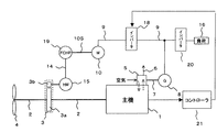
20は過給機5によって駆動され発電機8から出力される電力を定周波数の電力に変換するインバータ、16はインバータ20(第1のインバータともいう)を介して定周波数の電力が供給される船舶内の負荷で、電動機や電灯等の電気設備である。
10は発電機8の電力で直接駆動される電動機、17は、前記油圧モータ(Hydraulic Motor)15と共に油圧駆動システムを構成する可変容量式油圧ポンプ(Variable Capacity Hydraulic Pump)であり、前記電動機10によって駆動される。
10 is an electric motor that is directly driven by the electric power of the
21は主機1の負荷状況を監視し可変容量式油圧ポンプ17を制御するコントローラで、この制御によって可変容量式油圧ポンプ17から油圧ポンプ15へ送られる油圧量が調整され、これに伴い減速機3を介して油圧ポンプ15によって推進軸2に加勢される加勢力が調整される。
21 is a controller for controlling a variable displacement
また、このコントローラ21によって可変容量式油圧ポンプ17が制御されると電動機10、発電機8、過給機5にかかる負荷量、即ち過給機5の回転数も調整され、過給機5から主機1へ供給される空気量が制御される。
Further, when the variable displacement
この時、過給機5から主機1へ供給される空気量が主機1の負荷状態に応じて最適となるようにコントローラ21の設定を行っておけば、常に主機1へは最適な空気が供給され、主機1の運転効率を最適に保つことができる。
尚、主機1の負荷状況は、主機1の回転数、出力トルク、吸気圧、過給機5から主機1へ供給される圧縮圧、風量等を計測することにより把握できる。
At this time, if the
The load status of the
図1で示す本実施形態1の船舶用主機の余剰エネルギー回収システムは、主機1により推進軸2を介してプロペラ4を駆動する。推進軸2には、油圧モータ15が減速機3を介して接続されている。主機1に設けられた過給機5の出力軸7には発電機8が直結されており、この発電機8から供給される電力により直接電動機10が駆動される。
The surplus energy recovery system for a marine main engine according to the first embodiment shown in FIG. 1 drives the propeller 4 via the
電動機10は出力軸10Sを介して可変容量式油圧ポンプ17を駆動し、可変容量式油圧ポンプ17は回転によって得た圧油を油圧配管14を経て油圧モータ15まで送りこれを駆動する。この可変容量式油圧ポンプ17は主機1の負荷状況を監視しているコントローラ21によって制御され、油圧モータ15へ供給する油の圧力を制御する。その結果、油圧モータ15によって推進軸2に加勢される加勢力が変化するが、これにより電動機10、発電機8、過給機5にかかる負荷量が制御され、過給機5の回転数が制御される。その結果、過給機5から主機1へ供給される空気量が主機の負荷状態に応じた最適な流量に制御され、主機1の運転効率を最適なものに維持できる。
The
このように構成することにより、インバータ20により発電機8の出力電力が定周波数に変換されて船内負荷16へ供給され、また、発電機8の出力電力が電動機10、可変容量式油圧ポンプ17、油圧モータ15、減速機3を介して推進軸2への加勢力として利用されると共にコントローラ21によって可変容量式油圧モータ17を制御して油圧モータ15から推進軸2に加勢される加勢力を制御することによって過給機5の回転数を制御し、主機1へ供給される空気量を主機1の状態に応じた最適な量に制御でき、主機1の運転効率を最適なものに維持できる効果がある。
With this configuration, the output power of the
[実施形態2]
図2を参照して本発明の実施形態2について説明する。
図2において、図1で説明したものと同じ構成要素のものは同一符号を付し、重複する説明は適宜省くものとする。
[Embodiment 2]
A second embodiment of the present invention will be described with reference to FIG.
In FIG. 2, the same components as those described in FIG. 1 are denoted by the same reference numerals, and redundant description will be omitted as appropriate.
18は発電機8および電動機10間を接続する電気回路(電気ケーブル)9の途中に設けられるインバータ(第2のインバータともいう)で、このインバータ18は主機1の負荷状況を監視しているコントローラ21によって制御され、図1と同様に発電機8、過給機5の負荷量が制御される。その結果、過給機5から主機1へ供給される空気量が主機の負荷状態に応じた最適な流量に制御され、主機1はその運転効率を最適なものに維持できる。尚、19は固定容量油圧ポンプ(Fixed Capacity Hydraulic Pump)であり、前記電動機10の出力軸10Sに直結されて駆動され、その圧油によって油圧モータを駆動している。
このように構成した余剰エネルギー回収システムも、第1のインバータ20により発電機8の出力電力が定周波数に変換されて船内負荷16へ供給され、また、発電機8の出力電力が第2のインバータ18、電動機10、固定容量式油圧ポンプ19、油圧モータ15、減速機3を介して推進軸2への加勢力として利用されると共にコントローラ21によって第2のインバータ18を制御して油圧モータ15から推進軸2に加勢される加勢力を制御することによって過給機5の回転数を制御し、主機1へ供給される空気量を主機1の状態に応じた最適な量に制御でき、主機1の運転効率を最適なものに維持できる効果がある。
In the surplus energy recovery system configured as described above, the output power of the
[実施形態3]
図3を参照して本発明の実施形態3について説明する。
図3において、図1と同じ構成要素のものは同じ番号を付し、重複した説明は適宜省くものとする。
[Embodiment 3]
A third embodiment of the present invention will be described with reference to FIG.
In FIG. 3, the same components as those in FIG. 1 are denoted by the same reference numerals, and redundant description will be omitted as appropriate.
図1と異なる点は、推進軸2上の減速機3に替えて油圧駆動システムの油圧モータ15を設置し、この変更に伴って可変容量油圧ポンプ17を、減速機3を介して電動機10によって駆動するようにした点が異なっている。
The difference from FIG. 1 is that a
このように構成しても、インバータ20により発電機8の出力電力が定周波数に変換されて船内負荷16へ供給され、また、発電機8の出力電力が電動機10、減速機3、可変容量式油圧ポンプ17、油圧モータ15、を介して推進軸2への加勢力として利用されると共にコントローラ21によって可変容量式油圧ポンプ17を制御して油圧モータ15から推進軸2に加勢される加勢力を制御することによって過給機5の回転数を制御し、主機1へ供給される空気量を主機1の状態に応じた最適な量に制御でき、主機1の運転効率を最適なものに維持できる効果がある。
Even with this configuration, the output power of the
[実施形態4]
図4を参照して本発明の実施形態4について説明する。
図4において、図2と同じ構成要素のものは同じ番号を付し、重複する説明は適宜省くものとする。
[Embodiment 4]
A fourth embodiment of the present invention will be described with reference to FIG.
4, the same components as those in FIG. 2 are denoted by the same reference numerals, and redundant description will be omitted as appropriate.
図2と異なる点は、図2の実施形態2の場合、推進軸2上に設けていた減速機3を廃止し、油圧モータ15を直接推進軸2に設置した点が異なっている。
このように構成しても、第1のインバータ20により発電機8の出力電力が定周波数に変換されて船内負荷16へ供給され、また、発電機8の出力電力が第2のインバータ18、電動機10、固定容量式油圧ポンプ19、油圧モータ15を介して推進軸2への加勢力として利用されると共にコントローラ21によって第2のインバータ18を制御して油圧モータ15から推進軸2に加勢される加勢力を制御することによって過給機5の回転数を制御し、主機1へ供給される空気量を主機1の状態に応じた最適な量に制御でき、主機1の運転効率を最適なものに維持できる効果がある。
The difference from FIG. 2 is that in the case of
Even with this configuration, the output power of the
尚、図2あるいは図4の構成において、固定容量式油圧ポンプ19、油圧モータ15を省略して電動機10を直接推進軸2に設け、あるいは減速機3を介して推進軸2を駆動するように構成してもよい。
2 or 4, the fixed displacement
以上述べたように、本発明は主機の排気ガスに含まれる余剰エネルギーによって発電した電力を船舶内の電気設備に利用できるだけでなく推進軸の加勢にも利用でき、更に過給機の回転数を制御できるために主機1へ供給される空気量を主機の負荷状態に応じた最適な流量に制御でき、主機1の運転効率を最適なものに維持できる効果がある。
As described above, the present invention can use not only the electric power generated by the surplus energy contained in the exhaust gas of the main engine for the electrical equipment in the ship but also for the energization of the propulsion shaft, and further the rotational speed of the supercharger. Since it can be controlled, the amount of air supplied to the
1…主機、2…推進軸、3…減速機、4…船舶推進プロペラ、5…過給機、6…排気ダクト、7…過給機の出力軸、8…発電機、9…電気ケーブル、10…電動機、14…油圧配管、15…油圧モータ(Hydraulic Motor)、16…船舶内の電気設備、17…可変容量式油圧ポンプ(Variable Capacity Hydraulic Pump)、18…第2のインバータ、19…固定容量式油圧ポンプ(Fixed Capacity Hydraulic Pump)、20…第1のインバータ、21…コントローラ。
DESCRIPTION OF
Claims (5)
前記主機の排気ガスによって駆動される排気タービンおよびこの排気タービンによって駆動され空気を圧縮して前記主機に送り込む吸気ブロアを備えた過給機と、
前記過給機によって駆動され発電する発電機と、
前記発電機で発電した電力をインバータを介して定周波数の電力が供給される船舶内の電気設備と、
前記発電機で発電した電力によって駆動される電動機と、
前記電動機によって駆動される可変容量式油圧ポンプおよび当該可変容量式油圧ポンプから供給される圧油によって駆動され前記推進軸上に設けられた減速機を介して前記推進軸に対して駆動力を加勢する油圧モータを有する油圧駆動システムと、
前記主機の負荷状況に応じて前記可変容量式油圧ポンプを制御して前記過給機にかかる負荷量を制御し過給機から主機へ供給される空気量を制御するコントローラと、
から構成されたことを特徴とする船舶用主機の余剰エネルギー回収システム。 A main engine that drives the ship propeller through the propulsion shaft;
A turbocharger comprising an exhaust turbine driven by the exhaust gas of the main engine and an intake blower driven by the exhaust turbine to compress air and send it to the main engine;
A generator driven by the supercharger to generate electricity;
Electric equipment in a ship to which electric power generated at the generator is supplied with constant frequency power via an inverter,
An electric motor driven by the electric power generated by the generator;
A driving force is applied to the propulsion shaft via a variable displacement hydraulic pump driven by the electric motor and a pressure reducer provided on the propulsion shaft driven by pressure oil supplied from the variable displacement hydraulic pump. A hydraulic drive system having a hydraulic motor to perform,
A controller that controls the variable displacement hydraulic pump according to the load status of the main machine to control the amount of load applied to the supercharger and control the amount of air supplied from the supercharger to the main machine;
A surplus energy recovery system for a marine main engine characterized by comprising:
Priority Applications (1)
| Application Number | Priority Date | Filing Date | Title |
|---|---|---|---|
| JP2011119235A JP5704455B2 (en) | 2011-05-27 | 2011-05-27 | Surplus energy recovery system for marine main engines |
Applications Claiming Priority (1)
| Application Number | Priority Date | Filing Date | Title |
|---|---|---|---|
| JP2011119235A JP5704455B2 (en) | 2011-05-27 | 2011-05-27 | Surplus energy recovery system for marine main engines |
Publications (3)
| Publication Number | Publication Date |
|---|---|
| JP2012245886A JP2012245886A (en) | 2012-12-13 |
| JP2012245886A5 JP2012245886A5 (en) | 2014-07-10 |
| JP5704455B2 true JP5704455B2 (en) | 2015-04-22 |
Family
ID=47466778
Family Applications (1)
| Application Number | Title | Priority Date | Filing Date |
|---|---|---|---|
| JP2011119235A Active JP5704455B2 (en) | 2011-05-27 | 2011-05-27 | Surplus energy recovery system for marine main engines |
Country Status (1)
| Country | Link |
|---|---|
| JP (1) | JP5704455B2 (en) |
Families Citing this family (4)
| Publication number | Priority date | Publication date | Assignee | Title |
|---|---|---|---|---|
| JP6435553B2 (en) * | 2015-02-03 | 2018-12-12 | 株式会社三井E&Sマシナリー | Hybrid gas engine ship |
| JP2016216008A (en) * | 2015-05-26 | 2016-12-22 | ヤンマー株式会社 | Marine gear device |
| JP6475582B2 (en) * | 2015-07-03 | 2019-02-27 | ヤンマー株式会社 | Reduction reverse rotation machine and ship equipped with the same |
| KR102482212B1 (en) * | 2022-07-22 | 2022-12-27 | 이기동 | Low frequency switching generator |
Family Cites Families (4)
| Publication number | Priority date | Publication date | Assignee | Title |
|---|---|---|---|---|
| JP4452930B2 (en) * | 2006-06-06 | 2010-04-21 | 西芝電機株式会社 | Ship propulsion system |
| JP4752859B2 (en) * | 2008-04-14 | 2011-08-17 | 西芝電機株式会社 | Ship propulsion system |
| JP2011094536A (en) * | 2009-10-29 | 2011-05-12 | Mitsubishi Heavy Ind Ltd | Denitration device for ship, and ship provided therewith |
| JP5227372B2 (en) * | 2010-08-03 | 2013-07-03 | エムエーエヌ・ディーゼル・アンド・ターボ・フィリアル・アフ・エムエーエヌ・ディーゼル・アンド・ターボ・エスイー・ティスクランド | Ship propulsion system |
-
2011
- 2011-05-27 JP JP2011119235A patent/JP5704455B2/en active Active
Also Published As
| Publication number | Publication date |
|---|---|
| JP2012245886A (en) | 2012-12-13 |
Similar Documents
| Publication | Publication Date | Title |
|---|---|---|
| US20130239568A1 (en) | Turbo Assist | |
| JP5256237B2 (en) | Power turbine rotation speed control system using a hydraulic pump. | |
| JP2011063256A (en) | Marine propulsion device | |
| CN101328832B (en) | Turbine engine with power turbine | |
| WO2014058008A1 (en) | Hull resistance reduction system and hull resistance reduction method | |
| JP5704455B2 (en) | Surplus energy recovery system for marine main engines | |
| JP2008111384A (en) | Surplus exhaust energy recovery system for marine engine | |
| KR20100022495A (en) | Ship propulsion system with use of the exhaust gas energy of large marine diesel engines | |
| JP2019073141A (en) | Control method for vessel propulsion system, control device for vessel propulsion system, and vessel provided with control device | |
| JP2008213833A (en) | Powertrain, its operating method, and motorized vehicle therewith | |
| JP5312513B2 (en) | Ship propulsion system | |
| JP4285562B2 (en) | MOBILE BODY MOTOR DEVICE AND MOBILE BODY HAVING SAME | |
| JP2012245886A5 (en) | ||
| JP4452930B2 (en) | Ship propulsion system | |
| WO2011037164A1 (en) | Internal combustion engine system and ship | |
| JP4752859B2 (en) | Ship propulsion system | |
| JP5374489B2 (en) | Power generation equipment | |
| JP5146878B2 (en) | Ship propulsion system | |
| JP5612959B2 (en) | Marine prime mover system | |
| JP2012219710A (en) | Vehicle engine and exhaust turbine electric generator | |
| JP2013029111A (en) | Power generation method, turbine power generator, method of controlling turbine power generator, control device, and ship including the turbine power generator | |
| JP6364691B2 (en) | Supercharger surplus power recovery device for internal combustion engine | |
| JP6435553B2 (en) | Hybrid gas engine ship | |
| CN103387043B (en) | Watercraft electric propulsion system | |
| KR20220043306A (en) | Rotor Sail System And Shaft Generator Connection Method For Reducing Fuel Consumption |
Legal Events
| Date | Code | Title | Description |
|---|---|---|---|
| A521 | Written amendment |
Free format text: JAPANESE INTERMEDIATE CODE: A523 Effective date: 20140516 |
|
| A621 | Written request for application examination |
Free format text: JAPANESE INTERMEDIATE CODE: A621 Effective date: 20140516 |
|
| A977 | Report on retrieval |
Free format text: JAPANESE INTERMEDIATE CODE: A971007 Effective date: 20150109 |
|
| TRDD | Decision of grant or rejection written | ||
| A01 | Written decision to grant a patent or to grant a registration (utility model) |
Free format text: JAPANESE INTERMEDIATE CODE: A01 Effective date: 20150120 |
|
| A61 | First payment of annual fees (during grant procedure) |
Free format text: JAPANESE INTERMEDIATE CODE: A61 Effective date: 20150212 |
|
| R150 | Certificate of patent or registration of utility model |
Ref document number: 5704455 Country of ref document: JP Free format text: JAPANESE INTERMEDIATE CODE: R150 |