JP5704014B2 - Secondary battery monitoring device - Google Patents
Secondary battery monitoring device Download PDFInfo
- Publication number
- JP5704014B2 JP5704014B2 JP2011169114A JP2011169114A JP5704014B2 JP 5704014 B2 JP5704014 B2 JP 5704014B2 JP 2011169114 A JP2011169114 A JP 2011169114A JP 2011169114 A JP2011169114 A JP 2011169114A JP 5704014 B2 JP5704014 B2 JP 5704014B2
- Authority
- JP
- Japan
- Prior art keywords
- battery
- secondary battery
- deterioration
- amount
- rate
- Prior art date
- Legal status (The legal status is an assumption and is not a legal conclusion. Google has not performed a legal analysis and makes no representation as to the accuracy of the status listed.)
- Active
Links
Images


Description
本発明は、二次電池の監視装置に関し、特に、二次電池の劣化状態を監視する技術に関する。 The present invention relates to a monitoring apparatus for a secondary battery, and more particularly to a technique for monitoring a deterioration state of a secondary battery.
大電流での二次電池の充放電(以下、「ハイレート充放電」ともいう)が継続されると、二次電池の内部抵抗が一時的(可逆的)に上昇する場合がある。このような状態が継続すると、二次電池の劣化が促進されてしまう(以下、ハイレート充放電の継続に起因する電池の劣化を「ハイレート劣化」ともいう)。そのため、二次電池の状態がハイレート劣化が生じ得る状態であるか否かを適確に把握することが望ましい。 When charging / discharging of the secondary battery with a large current (hereinafter, also referred to as “high-rate charging / discharging”) is continued, the internal resistance of the secondary battery may increase temporarily (reversibly). If such a state continues, the deterioration of the secondary battery is promoted (hereinafter, the deterioration of the battery due to the continuation of the high rate charge / discharge is also referred to as “high rate deterioration”). Therefore, it is desirable to accurately grasp whether or not the state of the secondary battery is a state in which high rate deterioration can occur.
特開2009−123435号公報(特許文献1)には、リチウムイオン二次電池の状態がハイレート劣化が生じ得る状態であるか否かを評価するためのハイレート劣化評価値を算出し、そのハイレート劣化評価値を用いてハイレート劣化を抑制する技術が開示されている。具体的には、特許文献1では、電解液中のリチウム塩濃度の偏りの変化に対応させてバッテリ劣化評価値を算出し、バッテリ劣化評価値が目標値を超えたか否かに応じて放電電力を制限している。 Japanese Patent Application Laid-Open No. 2009-123435 (Patent Document 1) calculates a high-rate deterioration evaluation value for evaluating whether or not the state of a lithium ion secondary battery is a state where high-rate deterioration can occur. A technique for suppressing high rate deterioration using an evaluation value is disclosed. Specifically, in Patent Document 1, a battery deterioration evaluation value is calculated in response to a change in the deviation of the lithium salt concentration in the electrolyte, and the discharge power is determined depending on whether or not the battery deterioration evaluation value exceeds a target value. Is limiting.
また、特開2010−60406号公報(特許文献2)には、予め与えられた電池モデル式を用いてハイレート劣化の有無を推定する技術が開示されている。この電池モデル式では、電極における電気化学反応を示す式(「バトラー・ボルマーの式」と呼ばれる式)や、充放電時における電極の表面での電極反応、電極内部および電解液中のリチウムの拡散、各部位での電位分布や温度分布などがモデリングされている。この電池モデル式を用いると、実際に測定された電池の測定電圧Vrおよび測定温度Tbに対応する電池の推定電流Imを求めることができる。そして、電池モデルで求めた推定電流Imと実際に測定された測定電流Irとに乖離が発生したときにハイレート劣化が生じていると推定する。なお、以下の説明では、特許文献2に記載の電池モデル式を用いて推定電流Imや推定抵抗Rmなどの電池に関する情報を推定する制御を「SOH(State Of Health)制御」とも称する。
Japanese Patent Laying-Open No. 2010-60406 (Patent Document 2) discloses a technique for estimating the presence or absence of high-rate degradation using a battery model formula given in advance. In this battery model formula, the formula indicating the electrochemical reaction at the electrode (the formula called “Butler-Volmer formula”), the electrode reaction at the surface of the electrode during charge and discharge, the diffusion of lithium in the electrode and in the electrolyte The potential distribution and temperature distribution at each part are modeled. By using this battery model formula, it is possible to obtain the estimated current Im of the battery corresponding to the actually measured battery voltage Vr and the measured temperature Tb. Then, it is estimated that high-rate deterioration has occurred when a deviation occurs between the estimated current Im obtained from the battery model and the actually measured measured current Ir. In the following description, control for estimating information related to the battery such as the estimated current Im and the estimated resistance Rm using the battery model formula described in
上述の特許文献1、2に開示された従来技術では、ハイレート劣化を検出することはできても、ハイレート充放電の継続に伴なう二次電池の内部抵抗の一時的な上昇量(以下、「ハイレート抵抗上昇量」ともいう)そのものを推定することはできない。そのため、二次電池の劣化状態を正確には把握できず、急激なハイレート抵抗上昇が発生した場合に電池劣化保護が遅れたり、充放電の制限量を無駄に高くしたりすることを余儀なくされていた。
In the prior art disclosed in the above-mentioned
本発明は、上述の課題を解決するためになされたものであって、その目的は、二次電池におけるハイレート抵抗上昇量を適切に推定することである。 The present invention has been made to solve the above-described problems, and an object thereof is to appropriately estimate the amount of increase in the high-rate resistance in the secondary battery.
この発明に係る二次電池の監視装置は、二次電池の電池電流、電池電圧および電池温度を測定する測定部と、予め与えられた電池モデルに従って、電池電圧および電池温度の測定値に対応する電池電流を推定する電流推定部と、二次電池の充放電の継続に起因する二次電池の電池抵抗の一時的な上昇量をハイレート劣化量として算出するハイレート劣化量算出部とを備える。ハイレート劣化量算出部は、電池電流の測定値をIr、電池電流の測定値および電池電圧の測定値から求まる電池抵抗の測定値をRr、電池モデルに従って推定される電池電流の推定値をIm、電池電流の推定値と電池電圧の測定値と電池電流の測定値と電池温度の測定値とから求まる電池抵抗の推定値をRmとするとき、ハイレート劣化量を、(Im−Ir)/Im×Rrおよび(Im−Ir)/Ir×Rmのいずれか一方の算出式を用いて算出する。 The secondary battery monitoring device according to the present invention corresponds to the measurement values of the battery voltage and the battery temperature according to the measurement unit that measures the battery current, the battery voltage, and the battery temperature of the secondary battery, and the battery model that is given in advance A current estimation unit that estimates the battery current; and a high-rate deterioration amount calculation unit that calculates a temporary increase amount of the battery resistance of the secondary battery due to the continuation of charge and discharge of the secondary battery as a high-rate deterioration amount. The high-rate degradation amount calculation unit is Ir, the battery current measurement value is Ir, the battery resistance measurement value obtained from the battery current measurement value and the battery voltage measurement value is Rr, the battery current estimation value estimated according to the battery model is Im, When the estimated value of the battery resistance obtained from the estimated value of the battery current, the measured value of the battery voltage, the measured value of the battery current, and the measured value of the battery temperature is Rm, the high rate deterioration amount is (Im−Ir) / Im × Calculation is performed using one of Rr and (Im−Ir) / Ir × Rm.
好ましくは、ハイレート劣化量算出部は、ハイレート劣化量の上昇率を、(Im−Ir)/Imおよび(Im−Ir)/Irのいずれか一方の算出式を用いて算出する。 Preferably, the high-rate deterioration amount calculation unit calculates an increase rate of the high-rate deterioration amount using one of (Im−Ir) / Im and (Im−Ir) / Ir.
この発明の別の局面に係る二次電池の監視装置は、二次電池の電池電流、電池電圧および電池温度を測定する測定部と、二次電池の充放電の継続に起因する二次電池の電池抵抗の一時的な上昇量をハイレート劣化量として算出するハイレート劣化量算出部と、二次電池の経年劣化による電池抵抗の定常的な上昇量を磨耗劣化量として算出する磨耗劣化量算出部とを備える。磨耗劣化量算出部は、二次電池の充放電停止状態が所定時間以上継続した後に測定された電池電流および電池電圧から求まる電池抵抗の測定値をRR1、二次電池の未使用時の初期抵抗をRr0とするとき、磨耗劣化量をRR1−Rr0の算出式を用いて算出して記憶する。ハイレート劣化量算出部は、二次電池の充放電が可能な状態で測定された電池電流および電池電圧から求まる電池抵抗の測定値をRR2、記憶された磨耗劣化量をΔRaとするとき、ハイレート劣化量を、RR2−Rr0−ΔRaおよびRR2−RR1のいずれか一方の算出式を用いて算出する。 A monitoring device for a secondary battery according to another aspect of the present invention includes a measuring unit that measures a battery current, a battery voltage, and a battery temperature of a secondary battery, and a secondary battery that is caused by continuation of charging and discharging of the secondary battery. A high rate deterioration amount calculation unit that calculates a temporary increase amount of the battery resistance as a high rate deterioration amount, and a wear deterioration amount calculation unit that calculates a steady increase amount of the battery resistance due to aging of the secondary battery as a wear deterioration amount; Is provided. The wear deterioration amount calculation unit calculates the measured value of the battery resistance obtained from the battery current and the battery voltage measured after the charge / discharge stop state of the secondary battery continues for a predetermined time or longer as RR1, the initial resistance when the secondary battery is not used. When Rr0 is used, the wear deterioration amount is calculated and stored using the calculation formula of RR1-Rr0. The high-rate deterioration amount calculation unit is LR2 when the measured value of the battery resistance obtained from the battery current and the battery voltage measured in a state where the secondary battery can be charged and discharged is RR2, and the stored wear deterioration amount is ΔRa. The amount is calculated using one of the calculation formulas of RR2-Rr0-ΔRa and RR2-RR1.
好ましくは、監視装置は、ハイレート劣化量が所定値を超える場合に、二次電池がハイレート劣化状態であると判定する状態判定部をさらに備える。 Preferably, the monitoring device further includes a state determination unit that determines that the secondary battery is in the high rate deterioration state when the high rate deterioration amount exceeds a predetermined value.
好ましくは、監視装置は、状態判定部によって二次電池がハイレート劣化状態であると判定された場合、二次電池の充放電を制限し、二次電池がハイレート劣化状態であると判定されない場合、二次電池の充放電の制限を解除する充放電制御部をさらに備える。 Preferably, the monitoring device restricts charging / discharging of the secondary battery when the state determination unit determines that the secondary battery is in the high-rate deterioration state, and when the secondary battery is not determined to be in the high-rate deterioration state, It further includes a charge / discharge control unit that releases the restriction of charge / discharge of the secondary battery.
好ましくは、監視装置は、二次電池の充放電履歴に基づいて、二次電池の充放電の継続に起因する二次電池の劣化の度合いを示すハイレート劣化評価値を、二次電池の放電に応じて放電側に変化させ、二次電池の充電に応じて充電側に変化させるように算出する評価値算出部と、ハイレート劣化評価値と充電側閾値および放電側閾値との比較結果に応じて、ハイレート劣化量が増加した要因が充電および放電のいずれであるのかを判定する要因判定部とをさらに備える。 Preferably, the monitoring device sets a high rate deterioration evaluation value indicating a degree of deterioration of the secondary battery due to the continuation of charge / discharge of the secondary battery based on the charge / discharge history of the secondary battery to discharge of the secondary battery. In accordance with the comparison result of the evaluation value calculation unit that calculates to change to the discharge side according to the charge of the secondary battery and to change to the charge side according to the charging of the secondary battery, and the high-rate deterioration evaluation value And a factor determination unit for determining whether the factor that increased the high rate deterioration amount is charging or discharging.
好ましくは、監視装置は、二次電池の充電および放電のいずれか一方が制限された状態でハイレート劣化量が上昇した場合、ハイレート劣化量が増加した要因が、充電および放電のうち制限された方とは反対の方であると判定する要因判定部をさらに備える。 Preferably, when the high-rate deterioration amount increases in a state where one of the charging and discharging of the secondary battery is restricted, the monitoring device is the one in which the factor of the increase in the high-rate deterioration amount is restricted between charging and discharging. And a factor determination unit that determines that it is opposite.
好ましくは、二次電池は、車両に搭載されるリチウムイオン二次電池である。 Preferably, the secondary battery is a lithium ion secondary battery mounted on a vehicle.
本発明によれば、二次電池におけるハイレート抵抗上昇量を適切に推定することができる。 ADVANTAGE OF THE INVENTION According to this invention, the high rate resistance raise amount in a secondary battery can be estimated appropriately.
以下、図面を参照しつつ、本発明の実施の形態について説明する。以下の説明では、同一の部品には同一の符号を付してある。それらの名称および機能も同じである。したがって、それらについての詳細な説明は繰返さない。 Hereinafter, embodiments of the present invention will be described with reference to the drawings. In the following description, the same parts are denoted by the same reference numerals. Their names and functions are also the same. Therefore, detailed description thereof will not be repeated.
[実施の形態1]
図1は、本実施の形態に係る二次電池の監視装置を搭載した車両の構造を示す図である。車両は、エンジン100と、発電機(ジェネレータ)200と、PCU(Power Control Unit)300と、電池(バッテリ)400、電動機(モータ)500と、これらのすべてに接続されたECU(Electronic Control Unit)600とを含む。なお、図1に示す車両は、エンジン100、ジェネレータ200、モータ500を搭載したハイブリッド車両であるが、本発明を適用可能な車両は図1に示す車両に限定されず、電力エネルギを用いて走行する車両全般に適用可能である。
[Embodiment 1]
FIG. 1 is a diagram showing the structure of a vehicle equipped with a secondary battery monitoring device according to the present embodiment. The vehicle includes an
エンジン100が発生する動力は、動力分配機構700により、2経路に分割される。一方は減速機800を経由して車輪900を駆動する経路である。もう一方は、発電機200を駆動させて発電する経路である。
The power generated by the
発電機200は、動力分配機構700により分配されたエンジン100の動力により発電するが、発電機200により発電された電力は、車両の運転状態や、バッテリ400の残存容量(以下、単に「SOC(State Of Charge)」ともいう)の状態に応じて使い分けられる。たとえば、通常走行時や急加速時では、発電機200により発電された電力はそのままモータ500を駆動させる電力となる。一方、バッテリ400のSOCが予め定められた値よりも低い場合、発電機200により発電された電力は、PCU300のインバータ302により交流電力から直流電力に変換され、コンバータ304により電圧が調整された後、バッテリ400に蓄えられる。
The
バッテリ400は、複数のリチウムイオン二次電池セルを一体化したモジュールを、さらに複数直列に接続して構成された組電池である。リチウムイオン二次電池セルの正極は、リチウムイオン(以下「Li塩」ともいう)を可逆的に吸蔵/放出可能な材料(たとえばリチウム含有酸化物)から成り、充電過程においてLi塩を電解液に放出し、放電過程において電解液中のLi塩を吸蔵する。リチウムイオン二次電池セルの負極は、Li塩を可逆的に吸蔵/放出可能な材料(たとえば炭素)から成り、充電過程において電解液中のLi塩を吸蔵し、放電過程においてLi塩を電解液に放出する。
The
モータ500は、三相交流モータであり、バッテリ400に蓄えられた電力および発電機200により発電された電力の少なくともいずれか一方の電力により駆動する。モータ500の駆動力は、減速機800を経由して車輪900に伝えられる。これにより、モータ500は、エンジン100をアシストして車両を走行させたり、モータ500からの駆動力のみにより車両を走行させたりする。
一方、車両の回生制動時には、減速機800を経由して車輪900によりモータ500が駆動され、モータ500が発電機として作動させられる。これによりモータ500は、制動エネルギーを電力に変換する回生ブレーキとして作用する。モータ500により発電された電力は、インバータ302を経由してバッテリ400に蓄えられる。
On the other hand, at the time of regenerative braking of the vehicle, the
ECU600は、図示しないCPU(Central Processing Unit)およびメモリを内蔵し、当該メモリに記憶されたマップおよびプログラムに基づいて、所定の演算処理を実行するように構成される。
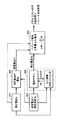
図2は、バッテリ400の周辺の構造を示す図である。図2に示すように、バッテリ400には、バッテリ400の両端電圧を検出する電圧センサ601と、バッテリ400の充放電電流を検出する電流センサ602と、バッテリ400の温度を検出する温度センサ603とが設けられる。これらの各センサは、検出結果をECU600に出力する。
FIG. 2 is a diagram illustrating a structure around the
ECU600は、電圧センサ601の検出値および電流センサ602の検出値からバッテリ400の充放電電力値を算出するとともに、充放電電流を積算してバッテリ400のSOCを算出する。
ECU600は、バッテリ400の充電電力制限値WINおよび放電電力制限値WOUT(単位はいずれもワット)を設定し、実際の充電電力およぼ放電電力がそれぞれ充電電力制限値WINおよび放電電力制限値WOUTを超えないように制御する。
本実施の形態に係るバッテリ400において、ハイレート充放電が継続的に行なわれると、内部抵抗が一時的(可逆的)に上昇し、バッテリ400の出力電圧が急激に低下する場合がある。この状態が続くと、バッテリ400の劣化が促進されてしまう。ハイレート充放電が継続的に行なわれることによる電解液中のLi塩の偏りが、この劣化の要因の1つと考えられている。
In
そこで、本実施の形態に係るECU600は、ハイレート充放電の継続に伴なうバッテリ400の内部抵抗の一時的(可逆的)な上昇量(以下、「ハイレート抵抗上昇量ΔRh」ともいう)を推定し、ハイレート抵抗上昇量ΔRhに基づいてハイレート劣化を検出する。具体的には、ECU600は、現在の電池劣化状態から決まるハイレート抵抗上昇量ΔRhそのものを推定し、推定したハイレート抵抗上昇量ΔRhと要求性能から求まるハイレート抵抗上昇量許容値ΔRhlimとを直接比較することでハイレート劣化の検出精度を向上させる。
Therefore,
図3は、本実施の形態に係るECU600の機能ブロック図である。図3に示した各機能ブロックは、ハードウェアによって実現してもよいし、ソフトウェアによって実現してもよい。
FIG. 3 is a functional block diagram of
ECU600は、取得部610,620と、抵抗算出部630と、推定部640と、ハイレート抵抗上昇量算出部650とを含む。
取得部610は、電流センサ602が検出したバッテリ400の充放電電流を取得する。以下の説明では、取得部610が取得したバッテリ充放電電流を「測定電流Ir」ともいう。
取得部620は、電圧センサ601が検出したバッテリ400の両端電圧および温度センサ603が検出したバッテリ400の温度を出力する。以下の説明では、取得部620が取得したバッテリ400の両端電圧および温度をそれぞれ「測定電圧Vr」および「測定温度Tb」ともいう。
抵抗算出部630は、測定電流Irおよび測定電圧Vrを用いて、バッテリ400の内部抵抗を算出する。抵抗算出部630は、測定電圧Vrと測定電流Irとの対応関係を複数サンプリングし、これらのサンプリング値からバッテリ400の内部抵抗を統計的に(たとえば最小2乗法を用いて)算出する。以下の説明では、抵抗算出部630が算出した内部抵抗を「測定抵抗Rr」ともいう。
推定部640は、バッテリ400の化学反応を簡易的にモデル化した電池モデルを用いて、推定電流Imや推定抵抗Rmなどのバッテリ400に関する内部パタメータを推定する。
The
推定部640は、測定電圧Vrおよび測定温度Tbを入力変数として電池モデルを用いてバッテリ400の充放電電流を推定する。より具体的には、推定部640は、測定電流Irおよび測定電圧Vrから複数の内部パラメータを求め、それらの内部パラメータを予め記憶された電池モデルに代入することで、バッテリ400の充放電電流を推定する。以下の説明では、推定部640が電池モデルを用いて推定したバッテリ400の充放電電流を「推定電流Im」ともいう。
The
また、推定部640は、推定電流Imと測定電圧Vrと測定電流Irと測定温度Tbとを入力変数として電池モデルを用いてバッテリ400の内部抵抗を推定する。以下の説明では、推定部640が電池モデルを用いて推定したバッテリ400の内部抵抗を「推定抵抗Rm」ともいう。
In addition, the
この電池モデルでは、バッテリ400の電極における電気化学反応を示す式(「バトラー・ボルマーの式」と呼ばれる式)や、充放電時における電極の表面での電極反応、電極内部および電解液中のリチウムの拡散、各部位での電位分布や温度分布など、バッテリ400の電解液中および電極内部で生じる化学反応のさまざまな特性がモデリングされている。この電池モデルを用いて算出される推定電流Imには、バッテリ400の経年劣化による内部抵抗の定常的(不可逆的)な上昇量(以下、「磨耗劣化量ΔRa」ともいう)の影響が反映されるが、急にハイレート抵抗上昇が発生した場合は電池モデルの推定抵抗の学習速度が追いつかずハイレート抵抗上昇量ΔRhの影響は反映されない。したがって、ハイレート充放電時には、推定電流Imと測定電流Irとの間にハイレート抵抗上昇量ΔRhに応じた乖離(以下、「推定電流差ΔI」ともいう)が発生する。なお、具体的な電池モデル式および推定電流Im、推定抵抗Rmの推定手法としては、たとえば従来技術である上述の特許文献2に記載の電池モデルおよびSOH制御を用いることができる。以下の説明では、このSOH制御を用いて推定電流Imおよび推定抵抗Rmを算出することを前提として説明するが、推定電流Imおよび推定抵抗Rmの算出手法は必ずしもこれに限定されるものではない。
In this battery model, an equation indicating an electrochemical reaction at the electrode of the battery 400 (an equation called “Butler-Volmer equation”), an electrode reaction on the surface of the electrode during charge and discharge, an inside of the electrode, and lithium in the electrolytic solution Various characteristics of chemical reactions occurring in the electrolyte solution of the
ハイレート抵抗上昇量算出部650は、測定電流Ir、推定電流Im、測定抵抗Rrを用いてハイレート抵抗上昇量ΔRhを算出する。具体的には、ハイレート抵抗上昇量算出部650は、ハイレート充放電時に推定電流Imと測定電流Irとの間にハイレート抵抗上昇量ΔRhに応じた乖離が発生する点に着目し、下記の式(1)よりハイレート抵抗上昇量ΔRhを推定する。
The high rate resistance increase
ΔRh=(Im−Ir)/Ir×Rm=(Im−Ir)/Im×Rr=(1−1/Dh)×Rr …(1)
式(1)において、「Im−Ir」は上述した推定電流差ΔIに相当する。「Dh」は電池抵抗上昇率であり、Rr/RmあるいはIm/Irで求まる値である。(Im−Ir)/Imは、測定抵抗Rrに対してハイレート抵抗上昇量ΔRhが占める割合に相当する。
ΔRh = (Im−Ir) / Ir × Rm = (Im−Ir) / Im × Rr = (1-1 / Dh) × Rr (1)
In Formula (1), “Im−Ir” corresponds to the estimated current difference ΔI described above. “Dh” is a battery resistance increase rate, and is a value obtained by Rr / Rm or Im / Ir. (Im−Ir) / Im corresponds to the ratio of the high rate resistance increase ΔRh to the measurement resistance Rr.
以下、式(1)の導出について詳細に説明する。
ハイレート抵抗上昇の有無は電池モデルを用いた従来のSOH制御では判別できず、結果的に、ハイレート充放電時には、SOH制御で求めた推定電流Imは、実際の測定電流Irよりも大きくなってしまう。そして、ハイレート充放電時の推定電流Imと測定電流Irとの乖離幅は、ハイレート充放電による内部抵抗の上昇量に応じて大きくなる。本実施の形態では、この点に着目し、推定電流Imと測定電流Irとの差(推定電流差ΔI)を用いてハイレート抵抗上昇量ΔRhを推定する。
Hereinafter, the derivation of Expression (1) will be described in detail.
Whether or not there is an increase in high-rate resistance cannot be determined by conventional SOH control using a battery model. As a result, during high-rate charge / discharge, the estimated current Im obtained by SOH control is larger than the actual measured current Ir. . The deviation width between the estimated current Im and the measured current Ir at the time of high rate charge / discharge increases in accordance with the increase amount of the internal resistance due to the high rate charge / discharge. In this embodiment, paying attention to this point, the high-rate resistance increase amount ΔRh is estimated using the difference between the estimated current Im and the measured current Ir (estimated current difference ΔI).
電池モデルによる推定値(推定抵抗Rm、推定電流Im)と実際の測定値(測定抵抗Rr、測定電流Ir)との関係を式(1a)に示す。式(1a)において、「ΔV」はバッテリ400の開放電圧(OCV:Open circuit voltage)からの電圧降下量を示す。
The relationship between the estimated value (estimated resistance Rm, estimated current Im) based on the battery model and the actual measured value (measured resistance Rr, measured current Ir) is shown in Expression (1a). In the formula (1a), “ΔV” represents the amount of voltage drop from the open circuit voltage (OCV) of the
ΔV=Rm・Im=Rr・Ir …(1a)
ハイレート抵抗上昇によって生じる推定電流Imと測定電流Irとの乖離幅を推定電流差ΔIと定義し、式(1b)に示す。
ΔV = Rm · Im = Rr · Ir (1a)
The deviation width between the estimated current Im and the measured current Ir caused by the increase in the high-rate resistance is defined as the estimated current difference ΔI, and is shown in the formula (1b).
ΔI=Im−Ir …(1b)
なお、推定電流差ΔIは、放電時は正の値となり、充電時は負の値となる。
ΔI = Im−Ir (1b)
The estimated current difference ΔI is a positive value during discharging and a negative value during charging.
ハイレート抵抗上昇量を含む測定抵抗Rrと、ハイレート抵抗上昇量を含まない基準抵抗Rstdと、ハイレート抵抗上昇量ΔRhとの関係を下記の式(1c)に示す。 The following equation (1c) shows the relationship among the measurement resistance Rr including the high rate resistance increase amount, the reference resistance Rstd not including the high rate resistance increase amount, and the high rate resistance increase amount ΔRh.
ΔRh=Rr−Rstd …(1c)
ここで、基準抵抗Rstdとは、磨耗劣化量ΔRaと新品抵抗Rr0との合計値(=ΔRa+Rr0)である。新品抵抗Rr0は、バッテリ400の未使用時の初期抵抗である。
ΔRh = Rr−Rstd (1c)
Here, the reference resistance Rstd is a total value (= ΔRa + Rr0) of the wear deterioration amount ΔRa and the new product resistance Rr0. The new resistance Rr0 is an initial resistance when the
式(1c)の両辺に測定電流Irを掛けて式(1d)のように変形すると、ハイレート抵抗上昇による実電圧降下量ΔVhrが求まる。 When both sides of the equation (1c) are multiplied by the measurement current Ir and transformed as in the equation (1d), the actual voltage drop amount ΔVhr due to the increase in the high-rate resistance is obtained.
ΔVhr=ΔRh・Ir=(Rr−Rstd)・Ir …(1d)
ここで、推定抵抗Rmにはハイレート抵抗上昇の影響は反映されておらず無視できるものと仮定すれば、推定抵抗Rmは基準抵抗Rstdと等しくなるため、上記の式(1c)、(1d)はそれぞれ下記の(1e)、(1f)に変形することができる。
ΔVhr = ΔRh · Ir = (Rr−Rstd) · Ir (1d)
Here, if it is assumed that the estimated resistance Rm does not reflect the effect of the increase in the high-rate resistance and can be ignored, the estimated resistance Rm is equal to the reference resistance Rstd. Therefore, the above equations (1c) and (1d) are Each can be modified into the following (1e) and (1f).
ΔRh=Rr−Rstd=Rr−Rm …(1e)
ΔVhr=ΔRh・Ir=(Rr−Rm)・Ir …(1f)
また、電池モデルの推定抵抗Rmが変化しない場合、ハイレート抵抗上昇の影響が推定電流Imに反映される。そのため、推定電流Imはハイレート抵抗上昇の影響が含まれないとした測定電流Irよりも大きくなる。その差に基づく電圧差をハイレート抵抗上昇による推定電圧降下量ΔVhmとすると推定電圧降下量ΔVhmは下記の式(1g)で求まる。
ΔRh = Rr−Rstd = Rr−Rm (1e)
ΔVhr = ΔRh · Ir = (Rr−Rm) · Ir (1f)
Further, when the estimated resistance Rm of the battery model does not change, the influence of the high rate resistance increase is reflected in the estimated current Im. Therefore, the estimated current Im is larger than the measured current Ir that does not include the effect of the high-rate resistance increase. Assuming that the voltage difference based on the difference is the estimated voltage drop amount ΔVhm due to the high-rate resistance rise, the estimated voltage drop amount ΔVhm can be obtained by the following equation (1g).
ΔVhm=Rm・ΔI=Rm・(Im−Ir) …(1g)
ハイレート抵抗上昇による電圧降下量ΔVhは、式(1a)に示すように推定電圧降下量ΔVhmと実電圧降下量ΔVhrとで等しいと仮定すると、式(1h)が導かれる。
ΔVhm = Rm · ΔI = Rm · (Im−Ir) (1 g)
Assuming that the estimated voltage drop amount ΔVhm is equal to the actual voltage drop amount ΔVhr as shown in the equation (1a), the equation (1h) is derived from the voltage drop amount ΔVh due to the high-rate resistance rise.
ΔVh=ΔVhm=ΔVhr …(1h)
式(1h)に、式(1f)、(1g)を代入すると、式(1i)が導かれる。
ΔVh = ΔVhm = ΔVhr (1h)
When the expressions (1f) and (1g) are substituted into the expression (1h), the expression (1i) is derived.
ΔVh=Rm・ΔI=ΔRh・Ir …(1i)
式(1i)をハイレート抵抗上昇量ΔRhで整理し、さらに式(1a)を代入してRmからRrに変換すると、上述した式(1)を導くことができる。
ΔVh = Rm · ΔI = ΔRh · Ir (1i)
If the formula (1i) is arranged by the high rate resistance increase amount ΔRh, and the formula (1a) is further substituted and converted from Rm to Rr, the above-described formula (1) can be derived.
このように、電池モデルで求めた推定電流Imを用いてハイレート抵抗上昇量ΔRhを推定する手法が導かれた。なお、式(1)は、式(1j)に示すように、電池抵抗上昇率Dhで整理することもできる。式(1j)に示す電池抵抗上昇率Dhは、測定抵抗Rrに含まれるハイレート抵抗上昇量ΔRhの割合を示す単純な式となる。 As described above, a method for estimating the high-rate resistance increase ΔRh using the estimated current Im obtained from the battery model has been derived. In addition, Formula (1) can also be arranged by battery resistance increase rate Dh, as shown in Formula (1j). The battery resistance increase rate Dh shown in Expression (1j) is a simple expression indicating the ratio of the high rate resistance increase amount ΔRh included in the measurement resistance Rr.
Dh=Rr/Rm=Im/Ir …(1j)
以上のように、本実施の形態では、ハイレート充放電時に電池モデル(SOH制御)で推定された推定電流Imと実際に測定された測定電流Irとの間にハイレート抵抗上昇量に応じた乖離(推定電流差ΔI)が発生する点に着目し、この推定電流差ΔIを用いてハイレート抵抗上昇量ΔRhを推定する。そのため、ハイレート抵抗上昇量ΔRhそのものを精度よく推定することができる。
Dh = Rr / Rm = Im / Ir (1j)
As described above, in the present embodiment, there is a divergence according to the amount of increase in the high-rate resistance between the estimated current Im estimated by the battery model (SOH control) during high-rate charge / discharge and the actually measured measured current Ir ( Paying attention to the point that the estimated current difference ΔI) occurs, the high-rate resistance increase ΔRh is estimated using the estimated current difference ΔI. Therefore, the high rate resistance increase amount ΔRh itself can be estimated with high accuracy.
また、たとえば、現在のハイレート抵抗上昇量ΔRhと要求性能から求まるハイレート抵抗上昇量許容値ΔRhlimとを直接比較した結果でハイレート劣化の有無を判定することが可能となる。そのため、ハイレート劣化の検出精度を向上させることができる。 In addition, for example, it is possible to determine the presence or absence of high-rate deterioration based on a direct comparison between the current high-rate resistance increase amount ΔRh and the high-rate resistance increase amount allowable value ΔRhlim obtained from the required performance. Therefore, the detection accuracy of high rate degradation can be improved.
また、本実施の形態に係るハイレート抵抗上昇量ΔRhの推定手法は、ハイレート抵抗上昇量ΔRhの推定精度を確保しつつ、オンボードで推定可能な形態である点および演算負荷が小さい点で優れている。 In addition, the high-rate resistance increase amount ΔRh estimation method according to the present embodiment is excellent in that it can be estimated on-board and the calculation load is small while ensuring the estimation accuracy of the high-rate resistance increase amount ΔRh. Yes.
従来技術においては、ハイレート抵抗上昇量そのものを精度よく推定できなかった。そのため、以下のような課題があった。すなわち、ハイレート抵抗上昇による電池経年劣化プロフィールは電池毎で異なるが、従来技術ではこの点を把握することができなかった。そのため、急激なハイレート抵抗上昇が発生した場合、電池劣化保護が遅れ、電池寿命を保証できなくなるおそれがあった。さらに、従来技術では、安全設計上、電池の使用開始当初から寿命までの生涯を通じて電池寿命年数の電池性能を目標値として設定する必要があった。そのため、使用期間が比較的短い間においては充放電の制限量が無駄に高くなり燃費ロスが生じていた。これに対し、本実施の形態では、上述のようにハイレート抵抗上昇量ΔRhそのものを精度よく推定することができるため、これらの従来技術の課題を解決し得る。 In the prior art, the high rate resistance increase amount itself could not be accurately estimated. Therefore, there are the following problems. That is, the battery aging degradation profile due to the increase in the high-rate resistance differs depending on the battery, but this point cannot be grasped by the conventional technology. Therefore, when a rapid increase in high-rate resistance occurs, the battery deterioration protection is delayed, and there is a possibility that the battery life cannot be guaranteed. Furthermore, in the prior art, for safety design, it was necessary to set the battery performance of the battery life years as a target value throughout the life from the beginning of use of the battery to the life. For this reason, during a relatively short period of use, the limit amount of charge / discharge is unnecessarily high, resulting in fuel consumption loss. On the other hand, in the present embodiment, as described above, the high rate resistance increase amount ΔRh itself can be estimated with high accuracy, so that the problems of these conventional techniques can be solved.
<実施の形態1の変形例>
上述の実施の形態1では、推定抵抗Rmを用いてハイレート抵抗上昇量ΔRhを算出したが、本変形例では、推定抵抗Rmを用いる部分を簡素化する。
<Modification of Embodiment 1>
In the first embodiment described above, the high-rate resistance increase amount ΔRh is calculated using the estimated resistance Rm. However, in this modification, the portion using the estimated resistance Rm is simplified.
図4は、本変形例に係るECU600の機能ブロック図である。なお、図4に示した機能ブロックのうち、前述の図3に示した機能ブロックと同じ符号を付している機能ブロックについては、既に説明したためここでの詳細な説明は繰り返さない。
FIG. 4 is a functional block diagram of
ECU600は、取得部610,620と、推定部640と、ハイレート抵抗上昇率算出部651とを含む。
ハイレート抵抗上昇率算出部651は、測定電流Irおよび推定電流Imから、式(2a)でハイレート抵抗上昇率γを算出する。
The high-rate resistance increase
γ=ΔI/Ir=ΔRh/Rm=ΔRhny/Rmny=Dh−1 …(2a)
この式(2a)は、実施の形態1で示した式(1)を抵抗比および電流比で整理し、ハイレート抵抗上昇量ΔRhおよび推定抵抗Rmを固定値とする(たとえばn年の規定年数劣化後の値ΔRhnyおよびRmnyとして予め規定する)ことで導出される。
γ = ΔI / Ir = ΔRh / Rm = ΔRh ny / Rm ny = Dh−1 (2a)
This formula (2a) is obtained by arranging the formula (1) shown in the first embodiment by the resistance ratio and the current ratio, and setting the high rate resistance increase ΔRh and the estimated resistance Rm as fixed values (for example, degradation of the specified number of years in n years). And later values ΔRh ny and Rm ny ).
この式(2a)より、オンボードでΔI/Irを求め、求めた値をハイレート抵抗上昇率γとして規定年数の許容値γlimnyと比較することで、ハイレート劣化の有無を判定する。すなわち、式(2b)が成立する場合に、ハイレート劣化が生じている状態と判定する。 From this equation (2a), ΔI / Ir is obtained on-board, and the obtained value is compared with an allowable value γlim ny of the specified number of years as a high-rate resistance increase rate γ to determine the presence or absence of high-rate deterioration. That is, when the formula (2b) is established, it is determined that the high rate deterioration has occurred.
γ=ΔI/Ir=Dh−1≧γlimny …(2b)
このように、本変形例では、推定抵抗Rmを用いることなく、規定年数後のハイレート抵抗上昇量ΔRhが許容値を超えるか否かに基づいてハイレート劣化の有無を判定することができる。
γ = ΔI / Ir = Dh−1 ≧ γlim ny (2b)
As described above, in this modification, it is possible to determine the presence or absence of high rate deterioration based on whether or not the high rate resistance increase amount ΔRh after the specified number of years exceeds the allowable value without using the estimated resistance Rm.
[実施の形態2]
上述の実施の形態1では、電池モデルに従って推定された推定電流Imを用いてハイレート抵抗上昇量ΔRhを推定した。
[Embodiment 2]
In the first embodiment described above, the high rate resistance increase ΔRh is estimated using the estimated current Im estimated according to the battery model.
これに対し、本実施の形態では、推定電流Imを用いることなく、ハイレート抵抗上昇量ΔRhを推定する。具体的には、放置中(充放電停止中)ではLi塩濃度拡散によりハイレート抵抗上昇が解消する点に着目し、ハイレート抵抗上昇の解消に必要な放置時間経過後に測定された測定抵抗Rrを用いて磨耗劣化量ΔRaを推定し、推定した磨耗劣化量ΔRaを記憶(学習)する。そして、走行中(充放電中)に、記憶された磨耗劣化量ΔRaを用いてハイレート抵抗上昇量ΔRhを推定する。 On the other hand, in the present embodiment, the high rate resistance increase amount ΔRh is estimated without using the estimated current Im. Specifically, paying attention to the fact that the increase in the high-rate resistance is solved by the diffusion of the Li salt concentration during standing (while charging / discharging is stopped), the measured resistance Rr measured after the standing time necessary for eliminating the high-rate resistance rise is used. The wear deterioration amount ΔRa is estimated, and the estimated wear deterioration amount ΔRa is stored (learned). Then, during running (during charging / discharging), the high rate resistance increase amount ΔRh is estimated using the stored wear deterioration amount ΔRa.
図5は、バッテリ400の内部抵抗の変化と本実施の形態に係るECU600の動作を模式的に示す図である。
FIG. 5 is a diagram schematically showing a change in the internal resistance of
バッテリ400の内部抵抗には、新品抵抗Rr0と、経年劣化(使用年数)に応じて不可逆的に増加する磨耗劣化量ΔRaと、ハイレート充放電中に一時的(可逆的)に増加するハイレート抵抗上昇量ΔRhとが含まれ得る。すなわち、式(3a)の関係が成立する。
The internal resistance of the
内部抵抗(=測定抵抗Rr)=Rr0+ΔR=Rr0+ΔRa+ΔRh …(3a)
式(3a)において、「ΔR」は新品抵抗Rr0からの内部抵抗上昇量であり、磨耗劣化量ΔRaとハイレート抵抗上昇量ΔRhとの合計値である。
Internal resistance (= measurement resistance Rr) = Rr0 + ΔR = Rr0 + ΔRa + ΔRh (3a)
In the equation (3a), “ΔR” is an internal resistance increase amount from the new resistance Rr0, and is a total value of the wear deterioration amount ΔRa and the high rate resistance increase amount ΔRh.
新品抵抗Rr0は変化せず、磨耗劣化量ΔRaも使用年数に応じて徐々に増加するものであり急激には増加せず、また一旦増加すると減少することもない。これに対し、ハイレート抵抗上昇量ΔRhは、ハイレート充放電時に増加するが、ハイレート充放電停止後は時間の経過とともにLi塩濃度が拡散することによって徐々に減少する。 The new resistance Rr0 does not change, and the wear deterioration amount ΔRa also increases gradually according to the years of use, does not increase rapidly, and does not decrease once it increases. On the other hand, the high rate resistance increase amount ΔRh increases at the time of high rate charge / discharge, but gradually decreases as the Li salt concentration diffuses with time after the high rate charge / discharge stop.
図5において、時刻t1以前は、車両走行中(充放電中)であり、内部抵抗には、新品抵抗Rr0と磨耗劣化量ΔRaとハイレート抵抗上昇量ΔRhとが含まれている。この状態では、ECU600は、磨耗劣化量ΔRaの学習を禁止しておく。
In FIG. 5, before time t1, the vehicle is running (charging / discharging), and the internal resistance includes a new resistance Rr0, a wear deterioration amount ΔRa, and a high rate resistance increase amount ΔRh. In this state,
時刻t1以降は、充放電が停止され、ハイレート抵抗上昇が徐々に解消され、ハイレート抵抗上昇量ΔRhが減少していく。時刻t1からハイレート抵抗上昇解消時間T1が経過した時刻t2では、ハイレート抵抗上昇量ΔRhが0となり、ハイレート抵抗上昇が完全に解消するため、式(3b)の関係が成立する。 After time t1, charging / discharging is stopped, the high-rate resistance increase is gradually eliminated, and the high-rate resistance increase amount ΔRh decreases. At the time t2 when the high-rate resistance increase elimination time T1 has elapsed from the time t1, the high-rate resistance increase amount ΔRh becomes 0, and the high-rate resistance increase is completely eliminated, so the relationship of Expression (3b) is established.
内部抵抗(=測定抵抗Rr)=Rr0+ΔRa …(3b)
ECU600は時刻t2にて磨耗劣化量ΔRaの学習を許可する。
Internal resistance (= measurement resistance Rr) = Rr0 + ΔRa (3b)
その後の時刻t3で車両走行が再開されると、ECU600は、磨耗劣化量ΔRaの学習が許可されているため、学習許可時間T2が経過する時刻t4までに測定された測定抵抗Rrを「測定抵抗RR1」として取得し、測定抵抗RR1から新品抵抗Rr0を減じた値を磨耗劣化量ΔRaとして算出して記憶(学習)する。すなわち、磨耗劣化量ΔRaの学習値は、式(3c)で算出される。
When the vehicle travel is resumed at the subsequent time t3, the
ΔRa=RR1−Rr0 …(3c)
そして、ECU600は、時刻t4以降の車両走行中において測定された測定抵抗Rrを「測定抵抗RR2」として取得し、測定抵抗RR2から磨耗劣化量ΔRaの学習値を減じた値をハイレート抵抗上昇量ΔRhとして算出する。
ΔRa = RR1-Rr0 (3c)
Then,
図6は、本実施の形態に係るECU600の機能ブロック図である。なお、図6に示した機能ブロックのうち、前述の図3に示した機能ブロックと同じ符号を付している機能ブロックについては、既に説明したためここでの詳細な説明は繰り返さない。
FIG. 6 is a functional block diagram of
ECU600は、取得部610,620と、抵抗算出部630と、学習部660と、減算部664,665とを含む。
学習部660は、磨耗劣化量ΔRaの学習制御を行なう。学習部660は、時間計測部661と、推定部662と、記憶部663とを含む。
The
時間計測部661は、放置時間τを計測する。本実施の形態において、「放置」とは、バッテリ400の充放電が停止された状態を意味し、車両の状態がREADY−OFF状態(車両走行不能状態)であることと等価である。したがって、「放置時間τ」とは、車両の状態がREADY−OFF状態に切り替えられた時点(図5では時刻t1)からの経過時間である。時間計測部661は、車両の状態がREADY−OFF状態からREADY−ON状態(走行可能状態)に切り替えられた時点(図5では時刻t3)で放置時間τの計測を停止し、計測した放置時間τを推定部662に出力する。
The
推定部662は、車両の状態がREADY−OFF状態からREADY−ON状態に切り替えられると、放置時間τがハイレート抵抗上昇解消時間T1を超えているか否かを判定する。ハイレート抵抗上昇解消時間T1は、たとえば実験等によって予め規定される。放置時間τがハイレート抵抗上昇解消時間T1を越えていない場合、推定部662は、磨耗劣化量ΔRaの学習を禁止する。放置時間τがハイレート抵抗上昇解消時間T1を越えている場合、推定部662は、READY−ON状態に切り替えらた時点から学習許可時間T2が経過する時点まで(図5では時刻t3から時刻t4まで)は、ハイレート充放電が行なわれないものとして、磨耗劣化量ΔRaの学習を許可する。
When the vehicle state is switched from the READY-OFF state to the READY-ON state, the
磨耗劣化量ΔRaの学習が許可された場合、推定部662は、学習許可時間T2が経過するまでに測定された測定抵抗Rrを「測定抵抗RR1」として取得する。この測定抵抗RR1には、ハイレート抵抗上昇量ΔRhが含まれていない点に着目し、推定部662は、測定抵抗RR1を用いて磨耗劣化量ΔRaを上述の式(3c)で推定する。
When learning of the wear deterioration amount ΔRa is permitted, the
記憶部663は、推定された磨耗劣化量ΔRaを記憶する。この際、測定温度TbやSOCなどをパラメータとして磨耗劣化量ΔRaをマップ化して記憶するようにしてもよい。この記憶部663に記憶された磨耗劣化量ΔRaが、磨耗劣化量ΔRaの学習値である。
The
図7は、上述の学習部660の機能を実現するためのECU600の処理手順を示すフローチャートである。以下に示すフローチャートの各ステップ(以下、ステップを「S」と略す)は、上述したようにハードウェアによって実現してもよいしソフトウェアによって実現してもよい。
FIG. 7 is a flowchart showing a processing procedure of
S10にて、ECU600は、放置中(充放電停止中)であるか否かを判定する。放電中でない場合(S10にてNO)、ECU600は処理をS15に移す。
In S10,
放置中である場合(S10にてYES)、ECU600は、S11にて放置時間τの計測を開始あるいは継続する。続くS12にて、ECU600は、放置時間τがハイレート抵抗上昇解消時間T1を越えているか否かを判定する。
If left unattended (YES at S10),
放置時間τがハイレート抵抗上昇解消時間T1を越えている場合(S12にてYES)、ECU600は、S13にて磨耗劣化量ΔRaの学習を許可する。放置時間τがハイレート抵抗上昇解消時間T1を越えていない場合(S12にてNO)、ECU600は、S14にて磨耗劣化量ΔRaの学習を禁止する。
When leaving time τ exceeds high-rate resistance increase elimination time T1 (YES in S12),
S15にて、ECU600は、READY−ON状態(充放電可能状態)となったか否かを判定する。READY−ON状態となっていない場合(S15にてNO)、ECU600は処理を終了させる。
In S15,
READY−ON状態となった場合(S15にてYES)、ECU600は、S16にて磨耗劣化量ΔRaの学習が許可されているか否かを判定する。磨耗劣化量ΔRaの学習が禁止されている場合(S16にてNO)、ECU600は、処理を終了させる。
When the state is READY-ON (YES in S15),
磨耗劣化量ΔRaの学習が許可されている場合(S16にてYES)、ECU600は、S17にて少なくとも学習許可時間T2が経過するまでに(ハイレート充放電が開始される前に)上述した測定抵抗RR1を取得し、S18にて磨耗劣化量ΔRaをRR1−Rr0として推定し、S19にて推定した磨耗劣化量ΔRaをメモリに記憶する。
If learning of wear deterioration amount ΔRa is permitted (YES in S16),
図6に戻って、減算部664,665について説明する。減算部664は、READY−ON状態(充放電可能状態)において測定抵抗Rrを「測定抵抗RR2」として取得し、測定抵抗RR2から新品抵抗Rr0を減じた値(=RR2−Rr0)を算出し、算出結果を減算部665に出力する。
Returning to FIG. 6, the
減算部665は、READY−ON状態において、減算部664から出力された値(=RR2−Rr0)から、メモリに記憶された磨耗劣化量ΔRaの学習値を減じた値を、ハイレート抵抗上昇量ΔRhとして出力する。すなわち、ハイレート抵抗上昇量ΔRhは、式(3d)で算出される。
In the READY-ON state, the
ΔRh=RR2−Rr0−ΔRa …(3d)
なお、上述した測定抵抗RR1を記憶しておき、ハイレート抵抗上昇量ΔRhを式(3c)で算出するようにしてもよい。
ΔRh = RR2-Rr0-ΔRa (3d)
Note that the above-described measurement resistance RR1 may be stored, and the high-rate resistance increase ΔRh may be calculated by the equation (3c).
ΔRh=RR2−RR1 …(3e)
以上のように、本実施の形態では、充放電停止後から十分に放置することによりハイレート抵抗上昇が解消する点に着目し、放置後の起動時(READY−OFF後に再びREADY−ONに切り替えられた時)において放置時間τがハイレート抵抗上昇解消時間T1を超えている場合には、ハイレート抵抗上昇が解消しておりかつ新たなハイレート充放電が行なわれていない測定抵抗RR1を用いて磨耗劣化量ΔRaを学習する。そのため、磨耗劣化量ΔRaを精度よく学習することができる。そして、走行中(充放電中)の測定抵抗RR2から磨耗劣化量ΔRaの学習値を減じた値をハイレート抵抗上昇量ΔRhとして推定する。そのため、ハイレート抵抗上昇量ΔRhの推定精度も向上する。
ΔRh = RR2-RR1 (3e)
As described above, in this embodiment, paying attention to the point that the high-rate resistance rise is eliminated by leaving the battery sufficiently after stopping charging / discharging, and switching to READY-ON again after starting (after READY-OFF). When the standing time τ exceeds the high-rate resistance rise elimination time T1, the amount of wear deterioration is measured using the measurement resistor RR1 in which the high-rate resistance rise is eliminated and new high-rate charge / discharge is not performed. Learn ΔRa. Therefore, the wear deterioration amount ΔRa can be learned with high accuracy. Then, a value obtained by subtracting the learned value of the wear deterioration amount ΔRa from the measured resistance RR2 during traveling (during charging / discharging) is estimated as the high rate resistance increase amount ΔRh. Therefore, the estimation accuracy of the high rate resistance increase amount ΔRh is also improved.
また、本実施の形態では、演算容量が小さくかつ演算負荷が低いため、オンボードでも安価かつ簡易に磨耗劣化量ΔRaおよびハイレート抵抗上昇量ΔRhを推定することができる。 In this embodiment, since the calculation capacity is small and the calculation load is low, the wear deterioration amount ΔRa and the high rate resistance increase amount ΔRh can be estimated easily and inexpensively even on-board.
<実施の形態2の変形例>
上述の実施の形態2では、放置後の起動時に、ハイレート抵抗上昇量ΔRhが解消しているものとして、起動時の測定抵抗Rrから磨耗劣化量ΔRaを学習し、その磨耗劣化量ΔRaの学習値を用いてハイレート抵抗上昇量ΔRhを推定した。
<Modification of
In the above-described second embodiment, it is assumed that the high rate resistance increase amount ΔRh has been eliminated at the start-up after being left, and the wear deterioration amount ΔRa is learned from the measurement resistance Rr at the start-up, and the learned value of the wear deterioration amount ΔRa is obtained. Was used to estimate the high rate resistance increase ΔRh.
これに対し、本変形例では、ハイレート抵抗上昇解消時の電池モデル(SOH制御)の内部パラメータで求めた推定電流Im0と現在の内部パラメータで求めた推定電流Imとの差を用いて、現在のハイレート抵抗上昇量ΔRhを推定する。 On the other hand, in this modification, using the difference between the estimated current Im0 obtained from the internal parameter of the battery model (SOH control) when the high-rate resistance rise is eliminated and the estimated current Im obtained from the current internal parameter, A high rate resistance increase amount ΔRh is estimated.
図8は、本実施の形態に係るECU600の機能ブロック図である。なお、図8に示した機能ブロックのうち、前述の図3に示した機能ブロックと同じ符号を付している機能ブロックについては、既に説明したためここでの詳細な説明は繰り返さない。
FIG. 8 is a functional block diagram of
ECU600は、取得部620と、推定部640A,640Bと、ハイレート抵抗上昇量算出部650Aとを含む。
推定部640A,640Bは、いずれも機能的には上述の図3に示す推定部640と同じである。ただし、推定部640A,640Bは、推定電流Imの算出に用いる内部パラメータが互いに異なる。具体的には、推定部640Aは、ハイレート抵抗上昇量ΔRhの解消時に記憶された内部パラメータを用いて推定電流Im0を算出する。したがって、推定部640Aが算出する推定電流Im0には、ハイレート抵抗上昇の影響が含まれていない。一方、推定部640Bは、現在の内部パラメータを用いて推定電流Imを算出する。したがって、推定部640Bが算出する推定電流Imは、ハイレート抵抗上昇の影響が含まれ得る。
The
ハイレート抵抗上昇量算出部650Aは、ハイレート抵抗上昇量ΔRhを下記の式()を用いて推定する。 The high-rate resistance increase amount calculation unit 650A estimates the high-rate resistance increase amount ΔRh using the following formula ().
ΔRh=(Im−Im0)/Im×Rr …(4)
以上のように、本変形例では、ハイレート抵抗上昇解消時の内部パラメータで求めた推定電流Im0と現在の内部パラメータで求めた推定電流Imとの差を用いて、現在のハイレート抵抗上昇量ΔRhを推定する。そのため、上述の実施の形態2と同様、ハイレート抵抗上昇量ΔRhの推定精度が向上するとともに、オンボードでも安価かつ簡易にハイレート抵抗上昇量ΔRhを推定することができる。
ΔRh = (Im−Im0) / Im × Rr (4)
As described above, in the present modification, the current high-rate resistance increase ΔRh is calculated using the difference between the estimated current Im0 obtained from the internal parameter when the high-rate resistance rise is eliminated and the estimated current Im obtained from the current internal parameter. presume. Therefore, as in the second embodiment, the estimation accuracy of the high rate resistance increase amount ΔRh is improved, and the high rate resistance increase amount ΔRh can be estimated easily and inexpensively even on-board.
[実施の形態3]
本実施の形態では、上述の実施の形態1,2で精度よく推定されたハイレート抵抗上昇量ΔRhを用いてハイレート劣化状態を精度よく判定するとともにハイレート劣化を適切に抑制する。
[Embodiment 3]
In the present embodiment, a high-rate degradation state is accurately determined using the high-rate resistance increase amount ΔRh accurately estimated in the first and second embodiments, and high-rate degradation is appropriately suppressed.
本実施の形態では、ハイレート抵抗上昇量ΔRhを用いたハイレート劣化判定と、バッテリ劣化評価値Dを用いたハイレート劣化抑制とを組合せることにより、ハイレート劣化状態に応じて、バッテリ400の充放電抑制量を可変的に選択する。
In the present embodiment, by combining high-rate deterioration determination using high-rate resistance increase amount ΔRh and high-rate deterioration suppression using battery deterioration evaluation value D, charging / discharging of
まず、バッテリ劣化評価値Dについて説明する。ECU600は、バッテリ400の電解液中のLi塩濃度の偏りの変化に応じてバッテリ劣化評価値Dを設定する。ECU600は、所定の基準値(後述する図9では「0」)を中心として、電解液中のLi塩濃度の偏りが放電側に大きいほどバッテリ劣化評価値Dを放電劣化側に変化させ、電解液中のLi塩濃度の偏りが充電側に大きいほどバッテリ劣化評価値Dを充電劣化側に変化させる。なお、具体的なバッテリ劣化評価値Dの算出手法としては、たとえば上述の特許文献1に記載された従来の算出手法を用いることができる。
First, the battery deterioration evaluation value D will be described.
次に、ハイレート抵抗上昇量ΔRhを用いたハイレート劣化判定およびバッテリ劣化評価値Dを用いたハイレート劣化抑制について説明する。 Next, high rate deterioration determination using the high rate resistance increase amount ΔRh and high rate deterioration suppression using the battery deterioration evaluation value D will be described.
図9は、ハイレート抵抗上昇量ΔRhおよびバッテリ劣化評価値Dの変化と本実施の形態に係るECU600の動作を模式的に示す図である。
FIG. 9 schematically shows changes in high rate resistance increase amount ΔRh and battery deterioration evaluation value D and the operation of
ECU600は、車両走行中において、ハイレート抵抗上昇量ΔRhが劣化量大閾値R1を超えると「ハイレート劣化」と判定する。図9においては、時刻t11〜t12、時刻t13〜t14までの期間で「ハイレート劣化」と判定される。
ここで、ハイレート劣化に放電側劣化と充電側劣化とがある電池の場合、逆側の充放電を抑制すると、ハイレート劣化が進行してしまう場合がある。そのため、ハイレート劣化が充電過多によるものか放電過多によるものかを適切に切り分け、その結果で充放電を抑制することが望ましい。しかしながら、ハイレート抵抗上昇量ΔRhは、ハイレート放電であってもハイレート充電であっても増加する。そのため、ハイレート抵抗上昇量ΔRhだけでは、ハイレート充電に起因する劣化(充電側劣化)であるのか、ハイレート放電に起因する劣化(放電側劣化)であるのかを切り分けできない。 Here, in the case of a battery in which high-rate degradation includes discharge-side degradation and charge-side degradation, high-rate degradation may progress if charging and discharging on the opposite side are suppressed. Therefore, it is desirable to appropriately determine whether the high rate deterioration is due to excessive charge or excessive discharge, and to suppress charging / discharging as a result. However, the high rate resistance increase amount ΔRh increases regardless of high rate discharge or high rate charge. For this reason, the high rate resistance increase amount ΔRh alone cannot be used to determine whether the deterioration is due to high rate charge (charge side deterioration) or the deterioration due to high rate discharge (discharge side deterioration).
そこで、ECU600は、「ハイレート劣化」と判定した場合、バッテリ劣化評価値Dと放電過多閾値および充電過多閾値とを比較し、その比較結果に応じてハイレート劣化が「放電側劣化」であるのか「充電側劣化」であるのかを切り分ける。具体的には、ECU600は、バッテリ劣化評価値Dが放電過多閾値を超えている場合(図9においてはバッテリ劣化評価値Dが放電過多閾値よりも放電側許容値に近づいた場合)、「放電側劣化」と判定する。そして、ECU600は、「放電側劣化」と判定した場合、バッテリ劣化評価値Dの放電側許容値(以下「D上限値」という)を初期値よりも徐々に縮小させる(基準値に近づける、図9では基準値「0」に近づくように低下させる)。そして、ECU600は、D上限値の縮小に応じてバッテリ400の放電を抑制(制限)する。一方、ECU600は、バッテリ劣化評価値Dが充電過多閾値を超えている場合(図9においてはバッテリ劣化評価値Dが充電過多閾値よりも充電側許容値に近づいた場合)、「充電側劣化」と判定する。そして、ECU600は、「充電側劣化」と判定した場合、バッテリ劣化評価値Dの充電側許容値(以下「D下限値」という)を初期値よりも徐々に縮小させる(基準値に近づける、図9では基準値「0」に近づくように増加させる)。そして、ECU600は、D下限値の縮小に応じてバッテリ400の充電を抑制する。
Therefore, when
また、ECU600は、車両走行中において、ハイレート抵抗上昇量ΔRhが劣化量小閾値R2(R2<R1)を下回ると「ハイレート劣化解消」と判定する。図9においては、時刻t16以降の期間で「ハイレート劣化解消」と判定される。
In addition, when the
ECU600は、「ハイレート劣化解消」と判定した場合、D上限値およびD下限値を徐々に初期値まで拡大させて、充放電の抑制を徐々に解除させる。
When
図10は、本実施の形態に係るECU600の機能ブロック図である。ECU600は、判定部670と、設定部671と、抑制部672とを含む。
FIG. 10 is a functional block diagram of
判定部670は、車両走行中において、ハイレート抵抗上昇量ΔRhと劣化量大閾値R1および劣化量小閾値R2とを比較し、その比較結果で「ハイレート劣化」および「ハイレート劣化解消」の判定を行なう。
The
また、判定部670は、「ハイレート劣化」と判定した場合には、バッテリ劣化評価値Dと放電過多閾値および充電過多閾値とを比較し、その比較結果に応じてハイレート劣化が「放電側劣化」であるのか「充電側劣化」であるのかを判定する(切り分ける)。
If the
設定部671は、判定部670の判定結果に応じて、D上限値およびD下限値を設定する。上述したように、設定部671は、「放電側劣化」であるときはD上限値を縮小させ(基準値に近づけ)、「充電側劣化」であるときはD下限値を縮小させる(基準値に近づける)。
The
図12〜13は、D上限値およびD下限値を可変的に設定する方法を例示した図である。なお、図12〜13にはD上限値のみを代表的に示している。図12に示すように、「放電側劣化」と判定された時点でD上限値をバッテリ劣化評価値Dにまで低下させるようにしてもよい。また、図13に示すように、D上限値を固定ステップ量で段階的に低下させるようにしてもよい。また、図14に示すように、「放電側劣化」と判定された時点のバッテリ劣化評価値Dを目標として、徐々に小さくなる複数の可変ステップ量を設定し、これらの可変ステップ量で段階的に目標まで低下させるようにしてもよい。 12 to 13 are diagrams illustrating a method of variably setting the D upper limit value and the D lower limit value. 12 to 13 typically show only the D upper limit value. As shown in FIG. 12, the D upper limit value may be lowered to the battery deterioration evaluation value D when it is determined as “discharge-side deterioration”. Further, as shown in FIG. 13, the D upper limit value may be decreased stepwise by a fixed step amount. Further, as shown in FIG. 14, a plurality of variable step amounts that are gradually reduced are set with the battery deterioration evaluation value D determined as “discharge-side deterioration” as a target, and step by step with these variable step amounts. You may make it fall to a target.
図10に戻って、抑制部672は、設定部671によって設定されたD上限値およびD下限値の増減に応じて、バッテリ400の充放電を抑制する。この充放電の抑制には、充電電力制限値WINおよび放電電力制限値WOUTが用いられる。すなわち、充電を抑制する場合には充電電力制限値WINが絞られ、放電を抑制する場合には、放電電力制限値WOUTが絞られる。
Returning to FIG. 10, the
なお、抑制部672は、D上限値およびD下限値の縮小量に応じて充放電量の抑制量(WIN、WOUTの絞り量)を設定する。これにより、D上限値およびD下限値に応じて充放電量の抑制量を可変的に設定することができる。そして、抑制部672は、設定した充放電量の抑制量を実現するように、実際のバッテリ400の充放電量を絞る。
The
なお、本実施の形態では、D上限値およびD下限値を用いて充放電を抑制する場合について説明する。しかし、図11に示すように、設定部671の機能を有さず(D上限値およびD下限値を用いずに)、抑制部672が判定部670の判定結果を用いて直接的に充放電を抑制するようにしてもよい。
In the present embodiment, the case where charging / discharging is suppressed using the D upper limit value and the D lower limit value will be described. However, as shown in FIG. 11, the
図15は、上述の機能を実現するためのECU600の処理手順を示すフローチャートである。
FIG. 15 is a flowchart showing a processing procedure of
S20にて、ECU600は、ハイレート抵抗上昇量ΔRhを推定する。具体的な推定手法としては、上述の実施の形態1、2で説明した手法を用いればよい。
In S20,
S21にて、ECU600は、ハイレート抵抗上昇量ΔRhが劣化量大閾値R1を超えているか否かを判定する。
In S21,
ハイレート抵抗上昇量ΔRhが劣化量大閾値R1を超えている場合(S21にてYES)、ECU600は、S22にて「ハイレート劣化」と判定し、S23にてハイレート劣化が充電側劣化なのか放電側劣化なのかを切り分ける処理を行なう。
When high rate resistance increase amount ΔRh exceeds large deterioration amount threshold value R1 (YES in S21),
図16は、ハイレート劣化の切り分け処理(図15のS23の処理)の詳細な処理手順を示すフローチャートである。 FIG. 16 is a flowchart showing a detailed processing procedure of the high-rate deterioration isolation process (the process of S23 of FIG. 15).
S23aにて、ECU600は、バッテリ劣化評価値Dが放電過多閾値を超えたか否かを判定する。なお、バッテリ劣化評価値Dは、上述したように、電解液中のLi塩濃度の偏りが放電側に大きいほど放電劣化側に変化し、電解液中のLi塩濃度の偏りが充電側に大きいほど充電劣化側に変化する値である。バッテリ劣化評価値Dは、他の処理で別途算出されている。
In S23a,
S23bにて、ECU600は、バッテリ劣化評価値Dが充電過多閾値を超えたか否かを判定する。
In S23b,
バッテリ劣化評価値Dが放電過多閾値を超えた場合(S23aにてYES)、ECU600は、S23cにて「放電側劣化」と判定する。
When battery deterioration evaluation value D exceeds the excessive discharge threshold (YES in S23a),
バッテリ劣化評価値Dが充電過多閾値を超えた場合(S23bにてYES)、ECU600は、S23dにて「充電側劣化」と判定する。
When battery deterioration evaluation value D exceeds the overcharge threshold (YES in S23b),
バッテリ劣化評価値Dが放電過多閾値および充電過多閾値を超えていない場合(S23aにてNOかつS23bにてNO)、ECU600は、S23eにて「切り分け不可」と判定する。
When battery deterioration evaluation value D does not exceed the excessive discharge threshold and excessive charge threshold (NO in S23a and NO in S23b),
図15に戻って、ECU600は、S24にて切り分け処理の結果が「放電側劣化」であるか否かを判定する。また、ECU600は、S25にて切り分け処理の結果が「充電側劣化」であるか否かを判定する。
Returning to FIG. 15,
切り分け処理の結果が「放電側劣化」である場合(S24にてYES)、ECU600は、S26にてD上限値を縮小させる。切り分け処理の結果が「充電側劣化」である場合(S25にてYES)、ECU600は、S27にてD下限値を縮小させる。切り分け処理の結果が「切り分け不可」である場合(S25にてNO)、ECU600は、S28にてD上限値およびD下限値の双方を縮小させる。
When the result of the separation process is “discharge-side deterioration” (YES in S24),
一方、ハイレート抵抗上昇量ΔRhが劣化量大閾値R1を超えていない場合(S21にてNO)、ECU600は、S29にてハイレート抵抗上昇量ΔRhが劣化量小閾値R2を下回るか否かを判定する。ハイレート抵抗上昇量ΔRhが劣化量小閾値R2を下回らない場合(S29にてNO)、ECU600は、処理を終了させる。
On the other hand, when high rate resistance increase amount ΔRh does not exceed large deterioration amount threshold value R1 (NO in S21),
ハイレート抵抗上昇量ΔRhが劣化量小閾値R2を下回る場合(S29にてYES)、ECU600は、S30にて「ハイレート劣化解消」と判定し、D上限値およびD下限値を徐々に拡大させる。
When high rate resistance increase amount ΔRh is smaller than deterioration amount small threshold value R2 (YES in S29),
ECU600は、S31にて、D上限値およびD下限値に基づいてバッテリ400の充放電を抑制(制限)する。具体的な抑制手法は上述したとおりである。
In S31,
ECU600は、S32にて、ハイレート劣化の再切り分け処理を行なう。
図17は、ハイレート劣化の再切り分け処理(図15のS32の処理)の処理手順を示すフローチャートである。
In step S32,
FIG. 17 is a flowchart showing the processing procedure of the high-rate deterioration re-segmentation process (the process of S32 in FIG. 15).
S32aにて、ECU600は、充放電の抑制(図15のS31の処理)を開始してから一定時間が経過したか否かを判定する。一定時間が経過していない場合(S32aにてNO)、ECU600は、一定時間が経過するまで待つ。
In S32a,
一定時間が経過した場合(S32aにてYES)、ECU600は、S32bにて充放電の抑制を開始した時点からハイレート抵抗上昇量ΔRhが増加したか否かを判定する。
When the predetermined time has elapsed (YES in S32a),
ハイレート抵抗上昇量ΔRhが増加した場合(S32bにてYES)、ECU600は、前回の切り分け処理(図15のS23の処理)の判定結果が誤りであるとし、前回の切り分け結果とは反対の判定を行なう。一方、ハイレート抵抗上昇量ΔRhが低下した場合(S32bにてNO)、ECU600は、前回の切り分け処理の判定結果が正しいとし、前回の切り分け処理の判定結果と同じ判定を行なう。
When high rate resistance increase amount ΔRh increases (YES in S32b),
図18は、ハイレート抵抗上昇量ΔRhの変化を示す図である。図18に示すように、時刻t21にて「充電側劣化」と判定して充電量を抑制したにも関わらずハイレート抵抗上昇量ΔRhが増加した場合は、ECU600によって、時刻t22にて「充電側劣化」との前回の切り分け結果を誤りであるとして反対の「放電側劣化」と再判定される。これにより、充電量の抑制が停止されるとともに、放電量の抑制が開始される。このように、前回の誤判定を修正して充放電を適切に抑制することで、誤判定による反対側の充放電抑制でハイレート抵抗上昇が促進されてしまうことを防ぐことができる。
FIG. 18 is a diagram showing a change in the high rate resistance increase amount ΔRh. As shown in FIG. 18, when the high rate resistance increase amount ΔRh increases in spite of determining the “charge side deterioration” at time t21 and suppressing the charge amount, the
以上のように、本実施の形態では、ハイレート抵抗上昇量ΔRhを用いたハイレート劣化判定と、バッテリ劣化評価値Dを用いたハイレート劣化抑制とを組合せることにより、ハイレート劣化状態に応じて、バッテリ400の充放電の抑制量を可変的に選択する。これにより、実際のハイレート抵抗上昇量に応じてバッテリ400の充放電を適切に抑制することができる。
As described above, in the present embodiment, by combining the high-rate deterioration determination using the high-rate resistance increase amount ΔRh and the high-rate deterioration suppression using the battery deterioration evaluation value D, the battery can be selected according to the high-rate deterioration state. The charge / discharge suppression amount of 400 is variably selected. Thereby, charging / discharging of the
今回開示された実施の形態はすべての点で例示であって制限的なものではないと考えられるべきである。本発明の範囲は上記した説明ではなくて特許請求の範囲によって示され、特許請求の範囲と均等の意味および範囲内でのすべての変更が含まれることが意図される。 The embodiment disclosed this time should be considered as illustrative in all points and not restrictive. The scope of the present invention is defined by the terms of the claims, rather than the description above, and is intended to include any modifications within the scope and meaning equivalent to the terms of the claims.
100 エンジン、200 ジェネレータ、300 PCU、302 インバータ、304 コンバータ、400 バッテリ、500 モータ、600 ECU、601 電圧センサ、602 電流センサ、603 温度センサ、610,620 取得部、630 抵抗算出部、640,640A,640B 推定部、650,650A ハイレート抵抗上昇量算出部、651 ハイレート抵抗上昇率算出部、660 学習部、661 時間計測部、662 推定部、663 記憶部、664,665 減算部、670 判定部、671 設定部、672 抑制部、700 動力分配機構、800 減速機、900 車輪。 100 engine, 200 generator, 300 PCU, 302 inverter, 304 converter, 400 battery, 500 motor, 600 ECU, 601 voltage sensor, 602 current sensor, 603 temperature sensor, 610, 620 acquisition unit, 630 resistance calculation unit, 640, 640A , 640B estimation unit, 650, 650A high rate resistance increase calculation unit, 651 high rate resistance increase rate calculation unit, 660 learning unit, 661 time measurement unit, 662 estimation unit, 663 storage unit, 664, 665 subtraction unit, 670 determination unit, 671 Setting part, 672 Suppression part, 700 Power distribution mechanism, 800 Reducer, 900 wheel.
Claims (7)
前記二次電池の電池電流、電池電圧および電池温度を測定する測定部と、
予め与えられた電池モデルに従って、前記電池電圧および前記電池温度の測定値に対応する前記電池電流を推定する電流推定部と、
前記二次電池の充放電の継続に起因する前記二次電池の電池抵抗の一時的な上昇量をハイレート劣化量として算出するハイレート劣化量算出部とを備え、
前記ハイレート劣化量算出部は、前記電池電流の測定値をIr、前記電池電流の測定値および前記電池電圧の測定値から求まる前記電池抵抗の測定値をRr、前記電池モデルに従って推定される前記電池電流の推定値をIm、前記電池電流の推定値と前記電池電圧の測定値と前記電池電流の測定値と前記電池温度の測定値とから求まる前記電池抵抗の推定値をRmとするとき、前記ハイレート劣化量を、(Im−Ir)/Im×Rrおよび(Im−Ir)/Ir×Rmのいずれか一方の算出式を用いて算出し、
前記監視装置は、前記ハイレート劣化量が所定値を超える場合に、前記二次電池がハイレート劣化状態であると判定する状態判定部をさらに備える、二次電池の監視装置。 A secondary battery monitoring device,
A measurement unit for measuring battery current, battery voltage and battery temperature of the secondary battery;
A current estimation unit for estimating the battery current corresponding to the measured values of the battery voltage and the battery temperature according to a battery model given in advance;
A high rate deterioration amount calculation unit that calculates a temporary increase amount of the battery resistance of the secondary battery due to continuation of charge and discharge of the secondary battery as a high rate deterioration amount;
The high-rate degradation amount calculation unit is configured to estimate the measured value of the battery current from Ir, the measured value of the battery resistance obtained from the measured value of the battery current and the measured value of the battery voltage to Rr, and the battery estimated according to the battery model. When the estimated value of current is Im, and the estimated value of the battery resistance obtained from the estimated value of the battery current, the measured value of the battery voltage, the measured value of the battery current, and the measured value of the battery temperature is Rm, The high rate deterioration amount is calculated using one of (Im−Ir) / Im × Rr and (Im−Ir) / Ir × Rm .
The monitoring apparatus further includes a state determination unit that determines that the secondary battery is in a high rate deterioration state when the high rate deterioration amount exceeds a predetermined value .
前記二次電池の電池電流、電池電圧および電池温度を測定する測定部と、
前記二次電池の充放電の継続に起因する前記二次電池の電池抵抗の一時的な上昇量をハイレート劣化量として算出するハイレート劣化量算出部と、
前記二次電池の経年劣化による前記電池抵抗の定常的な上昇量を磨耗劣化量として算出する磨耗劣化量算出部とを備え、
前記磨耗劣化量算出部は、前記二次電池の充放電停止状態が所定時間以上継続した後に測定された前記電池電流および前記電池電圧から求まる前記電池抵抗の測定値をRr1、前記二次電池の未使用時の初期抵抗をRr0とするとき、前記磨耗劣化量をRr1−Rr0の算出式を用いて算出して記憶し、
前記ハイレート劣化量算出部は、前記二次電池の充放電が可能な状態で測定された前記電池電流および前記電池電圧から求まる前記電池抵抗の測定値をRr2、記憶された前記磨耗劣化量をΔRaとするとき、前記ハイレート劣化量を、Rr2−Rr0−ΔRaおよびRr2−Rr1のいずれか一方の算出式を用いて算出する、二次電池の監視装置。 A secondary battery monitoring device,
A measurement unit for measuring battery current, battery voltage and battery temperature of the secondary battery;
A high rate deterioration amount calculation unit for calculating a temporary increase amount of the battery resistance of the secondary battery due to continuation of charge and discharge of the secondary battery as a high rate deterioration amount;
A wear deterioration amount calculation unit that calculates a steady increase amount of the battery resistance due to aging of the secondary battery as a wear deterioration amount;
The wear deterioration amount calculation unit calculates the measured value of the battery resistance obtained from the battery current and the battery voltage measured after the charge / discharge stop state of the secondary battery continues for a predetermined time or more as Rr1, the secondary battery When the initial resistance when not in use is Rr0, the wear deterioration amount is calculated and stored using a calculation formula of Rr1-Rr0,
The high-rate deterioration amount calculation unit Rr2 represents the measured value of the battery resistance obtained from the battery current and the battery voltage measured in a state where the secondary battery can be charged and discharged, and ΔRa represents the stored wear deterioration amount. Then, the high-rate deterioration amount is calculated using a calculation formula of any one of Rr2-Rr0-ΔRa and Rr2-Rr1.
前記二次電池の充放電履歴に基づいて、前記二次電池の充放電の継続に起因する前記二次電池の劣化の度合いを示すハイレート劣化評価値を、前記二次電池の放電に応じて放電側に変化させ、前記二次電池の充電に応じて充電側に変化させるように算出する評価値算出部と、
前記ハイレート劣化評価値と充電側閾値および放電側閾値との比較結果に応じて、前記
ハイレート劣化量が増加した要因が充電および放電のいずれであるのかを判定する要因判定部とをさらに備える、請求項1〜4のいずれかに記載の二次電池の監視装置。 The monitoring device
Based on the charge / discharge history of the secondary battery, a high rate deterioration evaluation value indicating the degree of deterioration of the secondary battery due to the continuation of charge / discharge of the secondary battery is discharged according to the discharge of the secondary battery. An evaluation value calculation unit that calculates the change to the charge side according to the charge of the secondary battery,
And a factor determination unit that determines whether the factor of the increase in the high rate degradation amount is charging or discharging according to a comparison result between the high rate degradation evaluation value and the charging side threshold value and the discharging side threshold value. Item 5. The secondary battery monitoring device according to any one of Items 1 to 4 .
Priority Applications (1)
| Application Number | Priority Date | Filing Date | Title |
|---|---|---|---|
| JP2011169114A JP5704014B2 (en) | 2011-08-02 | 2011-08-02 | Secondary battery monitoring device |
Applications Claiming Priority (1)
| Application Number | Priority Date | Filing Date | Title |
|---|---|---|---|
| JP2011169114A JP5704014B2 (en) | 2011-08-02 | 2011-08-02 | Secondary battery monitoring device |
Publications (2)
| Publication Number | Publication Date |
|---|---|
| JP2013032966A JP2013032966A (en) | 2013-02-14 |
| JP5704014B2 true JP5704014B2 (en) | 2015-04-22 |
Family
ID=47788964
Family Applications (1)
| Application Number | Title | Priority Date | Filing Date |
|---|---|---|---|
| JP2011169114A Active JP5704014B2 (en) | 2011-08-02 | 2011-08-02 | Secondary battery monitoring device |
Country Status (1)
| Country | Link |
|---|---|
| JP (1) | JP5704014B2 (en) |
Families Citing this family (6)
| Publication number | Priority date | Publication date | Assignee | Title |
|---|---|---|---|---|
| JP5704120B2 (en) * | 2012-05-29 | 2015-04-22 | トヨタ自動車株式会社 | Battery system and degradation state determination method |
| JP6040922B2 (en) * | 2013-11-29 | 2016-12-07 | トヨタ自動車株式会社 | Charging system |
| JP6261970B2 (en) * | 2013-12-06 | 2018-01-17 | Kddi株式会社 | Battery deterioration determination device, battery deterioration determination method, and battery deterioration determination program |
| JP6701936B2 (en) * | 2016-05-10 | 2020-05-27 | 日立化成株式会社 | Battery state detecting device, vehicle, program, and battery state detecting method |
| KR102182691B1 (en) | 2017-10-20 | 2020-11-24 | 주식회사 엘지화학 | Apparatus and method for estimating resistance of battery |
| JP6911746B2 (en) * | 2017-12-25 | 2021-07-28 | トヨタ自動車株式会社 | Battery information processing device, battery manufacturing support device, assembled battery, battery information processing method, and assembled battery manufacturing method |
Family Cites Families (4)
| Publication number | Priority date | Publication date | Assignee | Title |
|---|---|---|---|---|
| JP4682509B2 (en) * | 2003-11-26 | 2011-05-11 | 日産自動車株式会社 | Battery open voltage calculation method and charge amount calculation method |
| JP2007003438A (en) * | 2005-06-27 | 2007-01-11 | Nissan Motor Co Ltd | Charging rate estimation device for secondary battery |
| JP4494453B2 (en) * | 2007-11-13 | 2010-06-30 | トヨタ自動車株式会社 | Secondary battery control device and control method |
| JP5036662B2 (en) * | 2008-09-03 | 2012-09-26 | トヨタ自動車株式会社 | Secondary battery monitoring device and secondary battery system |
-
2011
- 2011-08-02 JP JP2011169114A patent/JP5704014B2/en active Active
Also Published As
| Publication number | Publication date |
|---|---|
| JP2013032966A (en) | 2013-02-14 |
Similar Documents
| Publication | Publication Date | Title |
|---|---|---|
| US9428177B2 (en) | Vehicle | |
| EP2306214B1 (en) | Determining battery DC impedance | |
| JP4494453B2 (en) | Secondary battery control device and control method | |
| CN107533109B (en) | Battery control device and electric vehicle system | |
| US10286806B2 (en) | Electrical storage system | |
| JP5704014B2 (en) | Secondary battery monitoring device | |
| JP4984527B2 (en) | Secondary battery charge state estimation device and charge state estimation method | |
| EP3352289A1 (en) | Storage battery control device | |
| JP6098496B2 (en) | Power storage system | |
| US9263909B2 (en) | Control device and control method for nonaqueous secondary battery | |
| JP5765375B2 (en) | Control apparatus and control method | |
| JP5009223B2 (en) | Secondary battery remaining capacity estimation method and apparatus | |
| JP2010066229A (en) | Device and method for detecting failure of battery | |
| US20160001672A1 (en) | Equivalent circuit based battery current limit estimations | |
| US9197078B2 (en) | Battery parameter estimation | |
| US20160023569A1 (en) | Battery power capability estimation based on reduced order electrochemical models | |
| JP6834757B2 (en) | Battery system | |
| JP3986992B2 (en) | Battery dischargeable capacity estimation method and apparatus | |
| JP6421986B2 (en) | Secondary battery charging rate estimation method, charging rate estimation device, and soundness estimation device | |
| JP5867373B2 (en) | Battery system and method for estimating internal resistance of lithium ion secondary battery | |
| JP7231657B2 (en) | battery controller | |
| JP2003068370A (en) | Detector of charged state of battery | |
| JP7100151B2 (en) | Battery control device | |
| JP4442275B2 (en) | How to detect battery status | |
| JP2020061823A (en) | Secondary battery control device |
Legal Events
| Date | Code | Title | Description |
|---|---|---|---|
| A621 | Written request for application examination |
Free format text: JAPANESE INTERMEDIATE CODE: A621 Effective date: 20140116 |
|
| A977 | Report on retrieval |
Free format text: JAPANESE INTERMEDIATE CODE: A971007 Effective date: 20140717 |
|
| A131 | Notification of reasons for refusal |
Free format text: JAPANESE INTERMEDIATE CODE: A131 Effective date: 20140729 |
|
| A521 | Written amendment |
Free format text: JAPANESE INTERMEDIATE CODE: A523 Effective date: 20140926 |
|
| TRDD | Decision of grant or rejection written | ||
| A01 | Written decision to grant a patent or to grant a registration (utility model) |
Free format text: JAPANESE INTERMEDIATE CODE: A01 Effective date: 20150127 |
|
| A61 | First payment of annual fees (during grant procedure) |
Free format text: JAPANESE INTERMEDIATE CODE: A61 Effective date: 20150209 |
|
| R151 | Written notification of patent or utility model registration |
Ref document number: 5704014 Country of ref document: JP Free format text: JAPANESE INTERMEDIATE CODE: R151 |