JP7100151B2 - Battery control device - Google Patents
Battery control device Download PDFInfo
- Publication number
- JP7100151B2 JP7100151B2 JP2020553120A JP2020553120A JP7100151B2 JP 7100151 B2 JP7100151 B2 JP 7100151B2 JP 2020553120 A JP2020553120 A JP 2020553120A JP 2020553120 A JP2020553120 A JP 2020553120A JP 7100151 B2 JP7100151 B2 JP 7100151B2
- Authority
- JP
- Japan
- Prior art keywords
- battery
- upper limit
- limit current
- ion concentration
- unit
- Prior art date
- Legal status (The legal status is an assumption and is not a legal conclusion. Google has not performed a legal analysis and makes no representation as to the accuracy of the status listed.)
- Active
Links
- 238000004364 calculation method Methods 0.000 claims description 124
- 238000009792 diffusion process Methods 0.000 claims description 103
- 238000007599 discharging Methods 0.000 claims description 60
- 230000006866 deterioration Effects 0.000 claims description 46
- 230000008859 change Effects 0.000 claims description 37
- 239000003792 electrolyte Substances 0.000 claims description 34
- HBBGRARXTFLTSG-UHFFFAOYSA-N Lithium ion Chemical compound [Li+] HBBGRARXTFLTSG-UHFFFAOYSA-N 0.000 description 178
- 229910001416 lithium ion Inorganic materials 0.000 description 178
- 150000002500 ions Chemical class 0.000 description 38
- 238000001514 detection method Methods 0.000 description 36
- 238000010586 diagram Methods 0.000 description 35
- 230000007423 decrease Effects 0.000 description 32
- 238000000034 method Methods 0.000 description 25
- 238000009826 distribution Methods 0.000 description 14
- 239000008151 electrolyte solution Substances 0.000 description 12
- 230000000694 effects Effects 0.000 description 9
- 238000004891 communication Methods 0.000 description 7
- 230000020169 heat generation Effects 0.000 description 6
- 230000003247 decreasing effect Effects 0.000 description 4
- 238000005259 measurement Methods 0.000 description 4
- 238000012545 processing Methods 0.000 description 4
- 238000012360 testing method Methods 0.000 description 4
- 230000001133 acceleration Effects 0.000 description 3
- PXHVJJICTQNCMI-UHFFFAOYSA-N Nickel Chemical compound [Ni] PXHVJJICTQNCMI-UHFFFAOYSA-N 0.000 description 2
- 241000156302 Porcine hemagglutinating encephalomyelitis virus Species 0.000 description 2
- 230000002159 abnormal effect Effects 0.000 description 2
- 239000003990 capacitor Substances 0.000 description 2
- 230000002542 deteriorative effect Effects 0.000 description 2
- 238000011156 evaluation Methods 0.000 description 2
- 238000002474 experimental method Methods 0.000 description 2
- 238000012986 modification Methods 0.000 description 2
- 230000004048 modification Effects 0.000 description 2
- 238000007086 side reaction Methods 0.000 description 2
- UFHFLCQGNIYNRP-UHFFFAOYSA-N Hydrogen Chemical compound [H][H] UFHFLCQGNIYNRP-UHFFFAOYSA-N 0.000 description 1
- WHXSMMKQMYFTQS-UHFFFAOYSA-N Lithium Chemical compound [Li] WHXSMMKQMYFTQS-UHFFFAOYSA-N 0.000 description 1
- 230000004913 activation Effects 0.000 description 1
- 230000015572 biosynthetic process Effects 0.000 description 1
- 238000009529 body temperature measurement Methods 0.000 description 1
- 238000006243 chemical reaction Methods 0.000 description 1
- 238000003487 electrochemical reaction Methods 0.000 description 1
- 238000005516 engineering process Methods 0.000 description 1
- 230000036541 health Effects 0.000 description 1
- 229910052739 hydrogen Inorganic materials 0.000 description 1
- 239000001257 hydrogen Substances 0.000 description 1
- 230000001771 impaired effect Effects 0.000 description 1
- 238000009413 insulation Methods 0.000 description 1
- 229910052744 lithium Inorganic materials 0.000 description 1
- 150000002642 lithium compounds Chemical class 0.000 description 1
- 230000007774 longterm Effects 0.000 description 1
- 229910052759 nickel Inorganic materials 0.000 description 1
- 230000010287 polarization Effects 0.000 description 1
- 230000008569 process Effects 0.000 description 1
- 230000008929 regeneration Effects 0.000 description 1
- 238000011069 regeneration method Methods 0.000 description 1
Images


Classifications
-
- G—PHYSICS
- G01—MEASURING; TESTING
- G01R—MEASURING ELECTRIC VARIABLES; MEASURING MAGNETIC VARIABLES
- G01R31/00—Arrangements for testing electric properties; Arrangements for locating electric faults; Arrangements for electrical testing characterised by what is being tested not provided for elsewhere
- G01R31/36—Arrangements for testing, measuring or monitoring the electrical condition of accumulators or electric batteries, e.g. capacity or state of charge [SoC]
- G01R31/382—Arrangements for monitoring battery or accumulator variables, e.g. SoC
-
- B—PERFORMING OPERATIONS; TRANSPORTING
- B60—VEHICLES IN GENERAL
- B60L—PROPULSION OF ELECTRICALLY-PROPELLED VEHICLES; SUPPLYING ELECTRIC POWER FOR AUXILIARY EQUIPMENT OF ELECTRICALLY-PROPELLED VEHICLES; ELECTRODYNAMIC BRAKE SYSTEMS FOR VEHICLES IN GENERAL; MAGNETIC SUSPENSION OR LEVITATION FOR VEHICLES; MONITORING OPERATING VARIABLES OF ELECTRICALLY-PROPELLED VEHICLES; ELECTRIC SAFETY DEVICES FOR ELECTRICALLY-PROPELLED VEHICLES
- B60L58/00—Methods or circuit arrangements for monitoring or controlling batteries or fuel cells, specially adapted for electric vehicles
- B60L58/10—Methods or circuit arrangements for monitoring or controlling batteries or fuel cells, specially adapted for electric vehicles for monitoring or controlling batteries
- B60L58/12—Methods or circuit arrangements for monitoring or controlling batteries or fuel cells, specially adapted for electric vehicles for monitoring or controlling batteries responding to state of charge [SoC]
- B60L58/15—Preventing overcharging
-
- B—PERFORMING OPERATIONS; TRANSPORTING
- B60—VEHICLES IN GENERAL
- B60L—PROPULSION OF ELECTRICALLY-PROPELLED VEHICLES; SUPPLYING ELECTRIC POWER FOR AUXILIARY EQUIPMENT OF ELECTRICALLY-PROPELLED VEHICLES; ELECTRODYNAMIC BRAKE SYSTEMS FOR VEHICLES IN GENERAL; MAGNETIC SUSPENSION OR LEVITATION FOR VEHICLES; MONITORING OPERATING VARIABLES OF ELECTRICALLY-PROPELLED VEHICLES; ELECTRIC SAFETY DEVICES FOR ELECTRICALLY-PROPELLED VEHICLES
- B60L58/00—Methods or circuit arrangements for monitoring or controlling batteries or fuel cells, specially adapted for electric vehicles
- B60L58/10—Methods or circuit arrangements for monitoring or controlling batteries or fuel cells, specially adapted for electric vehicles for monitoring or controlling batteries
- B60L58/12—Methods or circuit arrangements for monitoring or controlling batteries or fuel cells, specially adapted for electric vehicles for monitoring or controlling batteries responding to state of charge [SoC]
- B60L58/13—Maintaining the SoC within a determined range
-
- B—PERFORMING OPERATIONS; TRANSPORTING
- B60—VEHICLES IN GENERAL
- B60L—PROPULSION OF ELECTRICALLY-PROPELLED VEHICLES; SUPPLYING ELECTRIC POWER FOR AUXILIARY EQUIPMENT OF ELECTRICALLY-PROPELLED VEHICLES; ELECTRODYNAMIC BRAKE SYSTEMS FOR VEHICLES IN GENERAL; MAGNETIC SUSPENSION OR LEVITATION FOR VEHICLES; MONITORING OPERATING VARIABLES OF ELECTRICALLY-PROPELLED VEHICLES; ELECTRIC SAFETY DEVICES FOR ELECTRICALLY-PROPELLED VEHICLES
- B60L58/00—Methods or circuit arrangements for monitoring or controlling batteries or fuel cells, specially adapted for electric vehicles
- B60L58/10—Methods or circuit arrangements for monitoring or controlling batteries or fuel cells, specially adapted for electric vehicles for monitoring or controlling batteries
- B60L58/18—Methods or circuit arrangements for monitoring or controlling batteries or fuel cells, specially adapted for electric vehicles for monitoring or controlling batteries of two or more battery modules
- B60L58/21—Methods or circuit arrangements for monitoring or controlling batteries or fuel cells, specially adapted for electric vehicles for monitoring or controlling batteries of two or more battery modules having the same nominal voltage
-
- G—PHYSICS
- G01—MEASURING; TESTING
- G01R—MEASURING ELECTRIC VARIABLES; MEASURING MAGNETIC VARIABLES
- G01R31/00—Arrangements for testing electric properties; Arrangements for locating electric faults; Arrangements for electrical testing characterised by what is being tested not provided for elsewhere
- G01R31/36—Arrangements for testing, measuring or monitoring the electrical condition of accumulators or electric batteries, e.g. capacity or state of charge [SoC]
- G01R31/3644—Constructional arrangements
- G01R31/3648—Constructional arrangements comprising digital calculation means, e.g. for performing an algorithm
-
- G—PHYSICS
- G01—MEASURING; TESTING
- G01R—MEASURING ELECTRIC VARIABLES; MEASURING MAGNETIC VARIABLES
- G01R31/00—Arrangements for testing electric properties; Arrangements for locating electric faults; Arrangements for electrical testing characterised by what is being tested not provided for elsewhere
- G01R31/36—Arrangements for testing, measuring or monitoring the electrical condition of accumulators or electric batteries, e.g. capacity or state of charge [SoC]
- G01R31/367—Software therefor, e.g. for battery testing using modelling or look-up tables
-
- G—PHYSICS
- G01—MEASURING; TESTING
- G01R—MEASURING ELECTRIC VARIABLES; MEASURING MAGNETIC VARIABLES
- G01R31/00—Arrangements for testing electric properties; Arrangements for locating electric faults; Arrangements for electrical testing characterised by what is being tested not provided for elsewhere
- G01R31/36—Arrangements for testing, measuring or monitoring the electrical condition of accumulators or electric batteries, e.g. capacity or state of charge [SoC]
- G01R31/374—Arrangements for testing, measuring or monitoring the electrical condition of accumulators or electric batteries, e.g. capacity or state of charge [SoC] with means for correcting the measurement for temperature or ageing
-
- H—ELECTRICITY
- H01—ELECTRIC ELEMENTS
- H01M—PROCESSES OR MEANS, e.g. BATTERIES, FOR THE DIRECT CONVERSION OF CHEMICAL ENERGY INTO ELECTRICAL ENERGY
- H01M10/00—Secondary cells; Manufacture thereof
- H01M10/42—Methods or arrangements for servicing or maintenance of secondary cells or secondary half-cells
- H01M10/425—Structural combination with electronic components, e.g. electronic circuits integrated to the outside of the casing
-
- H—ELECTRICITY
- H01—ELECTRIC ELEMENTS
- H01M—PROCESSES OR MEANS, e.g. BATTERIES, FOR THE DIRECT CONVERSION OF CHEMICAL ENERGY INTO ELECTRICAL ENERGY
- H01M10/00—Secondary cells; Manufacture thereof
- H01M10/42—Methods or arrangements for servicing or maintenance of secondary cells or secondary half-cells
- H01M10/48—Accumulators combined with arrangements for measuring, testing or indicating the condition of cells, e.g. the level or density of the electrolyte
- H01M10/486—Accumulators combined with arrangements for measuring, testing or indicating the condition of cells, e.g. the level or density of the electrolyte for measuring temperature
-
- H—ELECTRICITY
- H02—GENERATION; CONVERSION OR DISTRIBUTION OF ELECTRIC POWER
- H02J—CIRCUIT ARRANGEMENTS OR SYSTEMS FOR SUPPLYING OR DISTRIBUTING ELECTRIC POWER; SYSTEMS FOR STORING ELECTRIC ENERGY
- H02J7/00—Circuit arrangements for charging or depolarising batteries or for supplying loads from batteries
- H02J7/0029—Circuit arrangements for charging or depolarising batteries or for supplying loads from batteries with safety or protection devices or circuits
- H02J7/00308—Overvoltage protection
-
- H—ELECTRICITY
- H02—GENERATION; CONVERSION OR DISTRIBUTION OF ELECTRIC POWER
- H02J—CIRCUIT ARRANGEMENTS OR SYSTEMS FOR SUPPLYING OR DISTRIBUTING ELECTRIC POWER; SYSTEMS FOR STORING ELECTRIC ENERGY
- H02J7/00—Circuit arrangements for charging or depolarising batteries or for supplying loads from batteries
- H02J7/0047—Circuit arrangements for charging or depolarising batteries or for supplying loads from batteries with monitoring or indicating devices or circuits
-
- H—ELECTRICITY
- H02—GENERATION; CONVERSION OR DISTRIBUTION OF ELECTRIC POWER
- H02J—CIRCUIT ARRANGEMENTS OR SYSTEMS FOR SUPPLYING OR DISTRIBUTING ELECTRIC POWER; SYSTEMS FOR STORING ELECTRIC ENERGY
- H02J7/00—Circuit arrangements for charging or depolarising batteries or for supplying loads from batteries
- H02J7/007—Regulation of charging or discharging current or voltage
- H02J7/00712—Regulation of charging or discharging current or voltage the cycle being controlled or terminated in response to electric parameters
- H02J7/00714—Regulation of charging or discharging current or voltage the cycle being controlled or terminated in response to electric parameters in response to battery charging or discharging current
-
- B—PERFORMING OPERATIONS; TRANSPORTING
- B60—VEHICLES IN GENERAL
- B60L—PROPULSION OF ELECTRICALLY-PROPELLED VEHICLES; SUPPLYING ELECTRIC POWER FOR AUXILIARY EQUIPMENT OF ELECTRICALLY-PROPELLED VEHICLES; ELECTRODYNAMIC BRAKE SYSTEMS FOR VEHICLES IN GENERAL; MAGNETIC SUSPENSION OR LEVITATION FOR VEHICLES; MONITORING OPERATING VARIABLES OF ELECTRICALLY-PROPELLED VEHICLES; ELECTRIC SAFETY DEVICES FOR ELECTRICALLY-PROPELLED VEHICLES
- B60L2240/00—Control parameters of input or output; Target parameters
- B60L2240/40—Drive Train control parameters
- B60L2240/54—Drive Train control parameters related to batteries
- B60L2240/545—Temperature
-
- B—PERFORMING OPERATIONS; TRANSPORTING
- B60—VEHICLES IN GENERAL
- B60L—PROPULSION OF ELECTRICALLY-PROPELLED VEHICLES; SUPPLYING ELECTRIC POWER FOR AUXILIARY EQUIPMENT OF ELECTRICALLY-PROPELLED VEHICLES; ELECTRODYNAMIC BRAKE SYSTEMS FOR VEHICLES IN GENERAL; MAGNETIC SUSPENSION OR LEVITATION FOR VEHICLES; MONITORING OPERATING VARIABLES OF ELECTRICALLY-PROPELLED VEHICLES; ELECTRIC SAFETY DEVICES FOR ELECTRICALLY-PROPELLED VEHICLES
- B60L2240/00—Control parameters of input or output; Target parameters
- B60L2240/40—Drive Train control parameters
- B60L2240/54—Drive Train control parameters related to batteries
- B60L2240/547—Voltage
-
- B—PERFORMING OPERATIONS; TRANSPORTING
- B60—VEHICLES IN GENERAL
- B60L—PROPULSION OF ELECTRICALLY-PROPELLED VEHICLES; SUPPLYING ELECTRIC POWER FOR AUXILIARY EQUIPMENT OF ELECTRICALLY-PROPELLED VEHICLES; ELECTRODYNAMIC BRAKE SYSTEMS FOR VEHICLES IN GENERAL; MAGNETIC SUSPENSION OR LEVITATION FOR VEHICLES; MONITORING OPERATING VARIABLES OF ELECTRICALLY-PROPELLED VEHICLES; ELECTRIC SAFETY DEVICES FOR ELECTRICALLY-PROPELLED VEHICLES
- B60L2240/00—Control parameters of input or output; Target parameters
- B60L2240/40—Drive Train control parameters
- B60L2240/54—Drive Train control parameters related to batteries
- B60L2240/549—Current
-
- H—ELECTRICITY
- H01—ELECTRIC ELEMENTS
- H01M—PROCESSES OR MEANS, e.g. BATTERIES, FOR THE DIRECT CONVERSION OF CHEMICAL ENERGY INTO ELECTRICAL ENERGY
- H01M10/00—Secondary cells; Manufacture thereof
- H01M10/05—Accumulators with non-aqueous electrolyte
- H01M10/052—Li-accumulators
-
- H—ELECTRICITY
- H01—ELECTRIC ELEMENTS
- H01M—PROCESSES OR MEANS, e.g. BATTERIES, FOR THE DIRECT CONVERSION OF CHEMICAL ENERGY INTO ELECTRICAL ENERGY
- H01M10/00—Secondary cells; Manufacture thereof
- H01M10/42—Methods or arrangements for servicing or maintenance of secondary cells or secondary half-cells
- H01M10/44—Methods for charging or discharging
-
- H—ELECTRICITY
- H01—ELECTRIC ELEMENTS
- H01M—PROCESSES OR MEANS, e.g. BATTERIES, FOR THE DIRECT CONVERSION OF CHEMICAL ENERGY INTO ELECTRICAL ENERGY
- H01M10/00—Secondary cells; Manufacture thereof
- H01M10/42—Methods or arrangements for servicing or maintenance of secondary cells or secondary half-cells
- H01M10/425—Structural combination with electronic components, e.g. electronic circuits integrated to the outside of the casing
- H01M2010/4271—Battery management systems including electronic circuits, e.g. control of current or voltage to keep battery in healthy state, cell balancing
-
- H—ELECTRICITY
- H01—ELECTRIC ELEMENTS
- H01M—PROCESSES OR MEANS, e.g. BATTERIES, FOR THE DIRECT CONVERSION OF CHEMICAL ENERGY INTO ELECTRICAL ENERGY
- H01M2220/00—Batteries for particular applications
- H01M2220/20—Batteries in motive systems, e.g. vehicle, ship, plane
-
- Y—GENERAL TAGGING OF NEW TECHNOLOGICAL DEVELOPMENTS; GENERAL TAGGING OF CROSS-SECTIONAL TECHNOLOGIES SPANNING OVER SEVERAL SECTIONS OF THE IPC; TECHNICAL SUBJECTS COVERED BY FORMER USPC CROSS-REFERENCE ART COLLECTIONS [XRACs] AND DIGESTS
- Y02—TECHNOLOGIES OR APPLICATIONS FOR MITIGATION OR ADAPTATION AGAINST CLIMATE CHANGE
- Y02E—REDUCTION OF GREENHOUSE GAS [GHG] EMISSIONS, RELATED TO ENERGY GENERATION, TRANSMISSION OR DISTRIBUTION
- Y02E60/00—Enabling technologies; Technologies with a potential or indirect contribution to GHG emissions mitigation
- Y02E60/10—Energy storage using batteries
-
- Y—GENERAL TAGGING OF NEW TECHNOLOGICAL DEVELOPMENTS; GENERAL TAGGING OF CROSS-SECTIONAL TECHNOLOGIES SPANNING OVER SEVERAL SECTIONS OF THE IPC; TECHNICAL SUBJECTS COVERED BY FORMER USPC CROSS-REFERENCE ART COLLECTIONS [XRACs] AND DIGESTS
- Y02—TECHNOLOGIES OR APPLICATIONS FOR MITIGATION OR ADAPTATION AGAINST CLIMATE CHANGE
- Y02T—CLIMATE CHANGE MITIGATION TECHNOLOGIES RELATED TO TRANSPORTATION
- Y02T10/00—Road transport of goods or passengers
- Y02T10/60—Other road transportation technologies with climate change mitigation effect
- Y02T10/7072—Electromobility specific charging systems or methods for batteries, ultracapacitors, supercapacitors or double-layer capacitors
-
- Y—GENERAL TAGGING OF NEW TECHNOLOGICAL DEVELOPMENTS; GENERAL TAGGING OF CROSS-SECTIONAL TECHNOLOGIES SPANNING OVER SEVERAL SECTIONS OF THE IPC; TECHNICAL SUBJECTS COVERED BY FORMER USPC CROSS-REFERENCE ART COLLECTIONS [XRACs] AND DIGESTS
- Y02—TECHNOLOGIES OR APPLICATIONS FOR MITIGATION OR ADAPTATION AGAINST CLIMATE CHANGE
- Y02T—CLIMATE CHANGE MITIGATION TECHNOLOGIES RELATED TO TRANSPORTATION
- Y02T90/00—Enabling technologies or technologies with a potential or indirect contribution to GHG emissions mitigation
- Y02T90/10—Technologies relating to charging of electric vehicles
- Y02T90/14—Plug-in electric vehicles
Description
本発明は、電池制御装置に関する。 The present invention relates to a battery control device.
電気自動車(EV)、プラグインハイブリッド自動車(PHEV)、ハイブリッド自動車(HEV)等に搭載される電池システムは、一般に、直列もしくは並列に接続された複数の二次電池と、各種電気部品から構成される。電気部品には、電池と負荷との電気的な接続のオンオフを制御するためのリレーや、電池の電流や電圧を測定するためのセンサ類、電池の充放電制御を行う電池制御装置などが含まれる。 Battery systems installed in electric vehicles (EVs), plug-in hybrid electric vehicles (PHEVs), hybrid electric vehicles (HEVs), etc. are generally composed of a plurality of secondary batteries connected in series or in parallel and various electric components. To. Electrical components include relays to control the on / off of the electrical connection between the battery and the load, sensors to measure the current and voltage of the battery, and a battery control device to control the charge and discharge of the battery. Is done.
電池制御装置は、電池を適切な範囲で使用するために、電池に流れる電流に対する制限値(上限電流値)を設定し、この上限電流値の範囲内で電池の充放電制御を行う。これにより、電池の電圧が急峻に変化する大電流領域での使用を避けて、電池の劣化を抑制している。 The battery control device sets a limit value (upper limit current value) for the current flowing through the battery in order to use the battery in an appropriate range, and performs charge / discharge control of the battery within this upper limit current value. As a result, deterioration of the battery is suppressed by avoiding use in a large current region where the voltage of the battery changes sharply.
大電流領域で電池電圧が急峻に変化する理由は、例えば、二次電池として一般的なリチウムイオン電池を用いた場合、電極と電解質との界面付近に形成される拡散層においてリチウムイオンの濃度勾配が発生することで、大電流通電時には電解質から電極へとリチウムイオンを供給するのに大きな過電圧が必要となるからである。したがって、大電流領域での電池の使用を避けるためには、充放電に伴って様々に変化する電極と電解質との界面付近の拡散層でのリチウムイオン濃度勾配に応じて、電池制御装置が上限電流値を適切に定めることが望ましい。 The reason why the battery voltage changes sharply in the large current region is, for example, when a general lithium ion battery is used as a secondary battery, the concentration gradient of lithium ions in the diffusion layer formed near the interface between the electrode and the electrolyte. This is because a large overvoltage is required to supply lithium ions from the electrolyte to the electrodes when a large current is applied. Therefore, in order to avoid the use of the battery in the large current region, the battery control device has an upper limit according to the lithium ion concentration gradient in the diffusion layer near the interface between the electrode and the electrolyte, which changes variously with charging and discharging. It is desirable to set the current value appropriately.
電解質のイオン濃度を考慮した二次電池の電流制限方法に関して、特許文献1に記載の技術が知られている。特許文献1では、二次電池に流れる電流値に基づいてイオン濃度の偏りを示す評価値を算出し、この評価値が目標値を超えたときに、二次電池の放電電力に対する上限値を低下させる技術が開示されている。
The technique described in
特許文献1に記載の技術では、電極と電解質との界面付近に形成される拡散層におけるイオン濃度勾配を考慮していないため、上述したような大電流領域での電池電圧の急峻な変化を考慮した上限電流値を設定することができない。
Since the technique described in
本発明による電池制御装置は、二次電池に流れる電流、または前記電流および前記二次電池の温度に基づいて、前記二次電池の電極と電解質との界面付近に形成される拡散層におけるイオン濃度勾配を推定する濃度勾配推定部と、前記イオン濃度勾配に基づいて前記二次電池の上限電流値を決定する上限電流決定部と、を備え、前記上限電流決定部は、前記イオン濃度勾配に応じた前記二次電池の過電圧が所定の範囲内となるように、前記上限電流値を決定する。 The battery control device according to the present invention has an ion concentration in a diffusion layer formed near the interface between the electrode of the secondary battery and the electrolyte based on the current flowing through the secondary battery or the current and the temperature of the secondary battery. The concentration gradient estimation unit for estimating the gradient and the upper limit current determination unit for determining the upper limit current value of the secondary battery based on the ion concentration gradient are provided, and the upper limit current determination unit responds to the ion concentration gradient. The upper limit current value is determined so that the overvoltage of the secondary battery is within a predetermined range.
本発明によれば、電極と電解質との界面付近に形成される拡散層におけるイオン濃度勾配によって生じる大電流領域での電池電圧の急峻な変化を考慮して、適切な上限電流値を設定することができる。 According to the present invention, an appropriate upper limit current value is set in consideration of a steep change in the battery voltage in the large current region caused by the ion concentration gradient in the diffusion layer formed near the interface between the electrode and the electrolyte. Can be done.
以下、本発明の実施形態を図面に基づいて説明する。以下の実施形態では、プラグインハイブリッド自動車(PHEV)の電源を構成する電池システムに対して本発明を適用した場合を例に挙げて説明する。ただし、以下に説明する実施形態の構成はこれに限らず、ハイブリッド自動車(HEV)、電気自動車(EV)などの乗用車や、ハイブリッド鉄道車両といった産業用車両の電源を構成する蓄電装置の蓄電器制御回路などにも適用できる。 Hereinafter, embodiments of the present invention will be described with reference to the drawings. In the following embodiment, a case where the present invention is applied to a battery system constituting a power source of a plug-in hybrid vehicle (PHEV) will be described as an example. However, the configuration of the embodiment described below is not limited to this, and the storage device control circuit of the power storage device constituting the power source of a passenger car such as a hybrid vehicle (HEV) or an electric vehicle (EV) or an industrial vehicle such as a hybrid railroad vehicle. It can also be applied to.
また、以下の実施形態では、リチウムイオン電池を採用した場合を例に挙げて説明するが、充放電可能な二次電池であれば、他にもニッケル水素電池、鉛電池、電気二重層キャパシタ、ハイブリッドキャパシタなどを用いることもできる。さらに、以下の実施形態では複数の単電池を直列に接続して組電池を構成しているが、複数の単電池を並列接続したものをさらに複数個直列に接続して組電池を構成してもよいし、直列接続した複数の単電池をさらに複数個並列に接続して組電池を構成してもよい。 Further, in the following embodiment, the case where a lithium ion battery is adopted will be described as an example, but if it is a rechargeable secondary battery, a nickel hydrogen battery, a lead battery, an electric double layer capacitor, etc. A hybrid capacitor or the like can also be used. Further, in the following embodiment, a plurality of cells are connected in series to form an assembled battery, but a plurality of cells connected in parallel are further connected in series to form an assembled battery. Alternatively, a plurality of single batteries connected in series may be further connected in parallel to form an assembled battery.
<第1の実施形態>
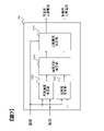
図1は、本発明の一実施形態に係る電池システム100とその周辺の構成を示す図である。電池システム100は、リレー300,310を介してインバータ400に接続される。電池システム100は、組電池110、単電池管理部120、電流検知部130、電圧検知部140、組電池制御部150、記憶部180を備える。<First Embodiment>
FIG. 1 is a diagram showing a configuration of a
組電池110は、複数の単電池111から構成される。単電池管理部120は、単電池111の状態を監視する。電流検知部130は、電池システム100に流れる電流を検知する。電圧検知部140は、組電池110の総電圧を検知する。組電池制御部150は、組電池110の状態を検知し、状態の管理等も行う。
The assembled
組電池110は、電気エネルギーの蓄積および放出(直流電力の充放電)が可能な複数の単電池111を電気的に直列に接続して構成されている。各単電池111には、例えば出力電圧が3.0~4.2V(平均出力電圧:3.6V)のリチウムイオン電池が用いられる。なお、これ以外の電圧仕様のものでも構わない。組電池110を構成する単電池111は、状態の管理・制御を実施する上で、所定の単位数にグループ分けされている。グループ分けされた単電池111は、電気的に直列に接続され、単電池群112a、112bを構成している。単電池群112を構成する単電池111の個数は、全ての単電池群112において同数でもよいし、単電池群112毎に単電池111の個数が異なっていてもよい。
The assembled
単電池管理部120は、組電池110を構成する単電池111の状態を監視する。単電池管理部120は、単電池群112毎に設けられた単電池制御部121を備える。図1では、単電池群112aと112bに対応して、単電池制御部121aと121bが設けられている。単電池制御部121は、単電池群112を構成する単電池111の状態を監視および制御する。
The
本実施形態では、説明を簡略化するために、4個の単電池111を電気的に直列接続して単電池群112aと112bを構成し、単電池群112aと112bをさらに電気的に直列接続して合計8個の単電池111を備える組電池110とした。
In the present embodiment, for simplification of the description, four
組電池制御部150には、単電池管理部120から出力される単電池111の電池電圧や温度の計測値、電流検知部130からの電流値、電圧検知部140から出力される組電池110の総電圧値、記憶部180に格納された単電池111の電池特性情報などが入力される。また、単電池管理部120は、単電池111が過充電もしくは過放電であるかの診断を行う機能や、単電池管理部120に通信エラーなどが発生した場合に異常信号を出力する機能を有しており、それらの診断結果や異常信号も組電池制御部150に入力される。さらに、上位の制御装置である車両制御部200からも信号が入力される。
The assembled
組電池制御部150は、入力された情報、および記憶部180に予め記憶されている電流制限値や単電池111の電池特性に基づいて、組電池110の充放電を適切に制御するための演算を行う。例えば、各単電池111に対する充放電電力の制限値の演算や、各単電池111の充電状態(SOC:State Of Charge)および劣化状態(SOHR:State Of Health based on Resistance)の演算や、各単電池111の電圧均等化制御を行うための演算などを実行する。組電池制御部150は、これらの演算結果や、その演算結果に基づく指令を、単電池管理部120や車両制御部200に出力する。
The assembled
記憶部180は、組電池110、単電池111、および単電池群112の電池特性に関する情報を格納する。なお、本実施形態では、記憶部180は組電池制御部150または単電池管理部120の外部に設置されている構成としたが、組電池制御部150または単電池管理部120が記憶部を備える構成とし、これに上記情報を格納してもよい。
The
組電池制御部150と単電池管理部120は、フォトカプラに代表される絶縁素子170および信号通信手段160を介して信号を送受信する。絶縁素子170を設けるのは、組電池制御部150と単電池管理部120は、動作電源が異なるためである。すなわち、単電池管理部120は、組電池110から電力をうけて動作するのに対して、組電池制御部150は、車載補機用のバッテリ(例えば14V系バッテリ)を電源として用いている。絶縁素子170は、単電池管理部120を構成する回路基板に実装してもよいし、組電池制御部150を構成する回路基板に実装してもよい。システム構成によっては、絶縁素子170を省略することもできる。
The assembled
組電池制御部150と、単電池管理部120を構成する単電池制御部121aおよび121bとの間の通信手段について説明する。単電池制御部121aおよび121bは、それぞれが監視する単電池群112aおよび112bの電位の高い順にしたがって直列に接続されている。組電池制御部150が単電池管理部120に送信した信号は、絶縁素子170および信号通信手段160を介して単電池制御部121aに入力される。単電池制御部121aの出力は信号通信手段160を介して単電池制御部121bに入力され、最下位の単電池制御部121bの出力は絶縁素子170および信号通信手段160を介して組電池制御部150へと伝送される。本実施形態では、単電池制御部121aと単電池制御部121bの間は絶縁素子170を介していないが、絶縁素子170を介して信号を送受信することもできる。
The communication means between the assembled
車両制御部200は、組電池制御部150が送信する情報を用いて、リレー300と310を介して電池システム100と接続されるインバータ400を制御する。車両走行中には、電池システム100はインバータ400と接続され、組電池110が蓄えているエネルギーを用いて、モータジェネレータ410を駆動する。
The
電池システム100を搭載した車両システムが始動して走行する場合には、車両制御部200の管理のもと、電池システム100はインバータ400に接続され、組電池110が蓄えているエネルギーを用いてモータジェネレータ410を駆動し、回生時はモータジェネレータ410の発電電力により組電池110が充電される。充電によって組電池110に蓄えられたエネルギーは、次回の車両走行時に利用されるか、車両内外の電装品等を動作させるためにも利用される。
When the vehicle system equipped with the
図2は、単電池制御部121の回路構成を示す図である。単電池制御部121は、電圧検出回路122、制御回路123、信号入出力回路124、温度検知部125を備える。電圧検出回路122は、各単電池111の端子間電圧を測定する。制御回路123は、電圧検出回路122および温度検知部125から測定結果を受け取り、信号入出力回路124を介して組電池制御部150に送信する。なお、単電池制御部121に一般的に実装される、自己放電や消費電流ばらつき等に伴い発生する単電池111間の電圧やSOCばらつきを均等化する回路構成は、周知のものであると判断して記載を省略した。
FIG. 2 is a diagram showing a circuit configuration of the
図2における単電池制御部121が備える温度検知部125は、単電池群112の温度を測定する機能を有する。温度検知部125は、単電池群112全体として1つの温度を測定し、単電池群112を構成する単電池111の温度代表値としてその温度を取り扱う。温度検知部125が測定した温度は、単電池111、単電池群112、または組電池110の状態を検知するための各種演算に用いられる。図2はこれを前提とするため、単電池制御部121に1つの温度検知部125を設けた。単電池111毎に温度検知部125を設けて単電池111毎に温度を測定し、単電池111毎の温度に基づいて各種演算を実行することもできるが、この場合は温度検知部125の数が多くなる分、単電池制御部121の構成が複雑となる。
The
図2では、簡易的に温度検知部125を示した。実際は温度測定対象に温度センサが設置され、設置した温度センサが温度情報を電圧として出力し、これを測定した結果が制御回路123を介して信号入出力回路124に送信され、信号入出力回路124が単電池制御部121の外に測定結果を出力する。この一連の流れを実現する機能が単電池制御部121に温度検知部125として実装され、温度情報(電圧)の測定には電圧検出回路122を用いることもできる。
In FIG. 2, the
図3は、本発明の第1の実施形態に係る組電池制御部150の機能構成を示す図である。組電池制御部150は、車両走行中に検出された各単電池111の電流値および電圧値をもとに、組電池110における各単電池111の状態や各単電池111に入出力可能な電力を決定する部分であり、その1つの機能構成要素として、各単電池111の充放電電力を制限するための充放電電力制限値(充電電力制限値および放電電力制限値)の演算を行う機能を有する。図3は、この充放電電力制限値の演算に関する組電池制御部150の機能構成を示している。これは、本発明の一実施形態に係る電池制御装置に相当する機能を担う部分である。なお、組電池制御部150は充放電電力制限値の演算機能以外にも、組電池110の制御に必要な各種機能、例えば各単電池111の電圧均等化制御を行う機能などを有しているが、これらは周知の機能であり、また本発明とは直接関係がないため、以下では詳細な説明を省略する。
FIG. 3 is a diagram showing a functional configuration of the assembled
図3に示すように、組電池制御部150は、その機能として、電池状態検知部151、上限電流演算部152、および充放電可能電力演算部153の各機能ブロックを有する。組電池制御部150は、これらの機能ブロックにより、電流検知部130が検知した組電池110の電流、すなわち各単電池111の電流や、単電池管理部120が検知した各単電池111の電圧および温度に基づいて、各単電池111の充放電電力制限値を演算する。
As shown in FIG. 3, the assembled
なお、上記では組電池制御部150が各単電池111の充放電電力制限値を演算することとして説明したが、複数の単電池111をまとめて充放電電力制限値を算出してもよい。例えば、単電池群112a,112bごとに算出したり、組電池110全体で算出したりすることができる。これらの場合でも、単電池111と同様の処理で充放電電力制限値を算出できる。また、各単電池111の充放電電力制限値は、同様の処理によって算出できる。そのため以下では、充放電電力制限値の算出対象を単に「電池」と称して、組電池制御部150における充放電電力制限値の演算機能を説明する。
In the above description, the assembled
電池状態検知部151は、組電池制御部150に入力される各電池の電流、電圧、温度の情報をもとに、各電池のSOCやSOHRを演算する。なお、SOCやSOHRの演算方法については、公知であるものとして説明を省略する。
The battery
上限電流演算部152は、各電池の電流と温度を入力として、各電池の充電時の上限電流を規定する充電側上限電流と、各電池の放電時の上限電流を規定する放電側上限電流とを演算して出力する。なお、上限電流演算部152による充電側上限電流および放電側上限電流の具体的な演算方法については後述する。
The upper limit
充放電可能電力演算部153は、電池状態検知部151が演算した各電池のSOCおよびSOHRと、組電池制御部150に入力される各電池の温度と、上限電流演算部152が演算した各電池の充電側上限電流および放電側上限電流をもとに、各電池の充電可能電力および放電可能電力を演算し、これらの演算結果に基づいて、各電池の充電電力制限値および放電電力制限値を出力する。なお、充電可能電力および放電可能電力の演算方法については後述する。
The charge / discharge rechargeable
続いて、上限電流演算部152による充電側上限電流および放電側上限電流の具体的な演算方法について、図4~図9を参照して説明する。
Subsequently, a specific calculation method of the charge side upper limit current and the discharge side upper limit current by the upper limit
図4は、上限電流の定義を説明する図である。図4では、電池に一定の電流を連続通電したときの所定時間経過後の電圧を、充電方向と放電方向に電流の大きさをそれぞれ変化させてプロットしたグラフの一例を示している。図4の横軸は電流を、縦軸は電圧を表している。図4において、四角で示した各プロット点は、3つの曲線上にそれぞれ存在している。これら3つの曲線は、それぞれ電圧を測定するタイミング、つまり、電池への通電を開始してからの経過時間が異なることを示している。 FIG. 4 is a diagram illustrating the definition of the upper limit current. FIG. 4 shows an example of a graph in which the voltage after a lapse of a predetermined time when a constant current is continuously applied to a battery is plotted by changing the magnitude of the current in the charging direction and the discharging direction. The horizontal axis of FIG. 4 represents current, and the vertical axis represents voltage. In FIG. 4, each plot point shown by a square exists on each of the three curves. These three curves show that the timing of measuring the voltage, that is, the elapsed time from the start of energization of the battery is different.
一般に、電池に一定の電流を連続的に通電した場合、通電時間の経過に伴って内部抵抗が上昇するため、電池の電圧はOCVから次第に乖離する。つまり、通電時間が長くなるほど内部抵抗値が上昇する。ここで図4に示すように、電池に流れる電流がある電流値を超えると、充電、放電ともに、電圧が急峻に変化する領域が発現することが知られている。この領域は、電池内で電極と電解質との界面へのリチウムイオンの拡散が律速となる領域に相当するものである。すなわち、この領域ではリチウムイオンの拡散に起因する抵抗成分が増大することにより、電池の電圧が急峻に変化する。 Generally, when a constant current is continuously applied to a battery, the internal resistance increases with the passage of the energization time, so that the voltage of the battery gradually deviates from the OCV. That is, the longer the energization time, the higher the internal resistance value. Here, as shown in FIG. 4, it is known that when the current flowing through the battery exceeds a certain current value, a region in which the voltage suddenly changes appears in both charging and discharging. This region corresponds to a region in the battery where the diffusion of lithium ions to the interface between the electrode and the electrolyte is rate-determining. That is, in this region, the voltage of the battery changes abruptly due to the increase in the resistance component due to the diffusion of lithium ions.
上記のようにリチウムイオンの拡散が律速となる領域では、電池を使用し続けると入出力性能の低下に繋がる可能性があるため、電池の使用をできるだけ避けることが好ましい。そこで本実施形態では、上限電流演算部152において、この領域に入る直前の電流を上限電流として定義し、このときの電流値を上限電流値として設定することで、当該領域での電池の使用を回避するようにしている。
In the region where the diffusion of lithium ions is rate-determining as described above, it is preferable to avoid the use of the battery as much as possible because the continuous use of the battery may lead to the deterioration of the input / output performance. Therefore, in the present embodiment, the upper limit
しかし、図4のグラフにおいて、リチウムイオンの拡散が律速となる領域に移行する電流の大きさは、曲線ごとに異なっている。したがって、上限電流値に設定すべき電流の大きさは、通電時間の違いに応じて様々に異なることが分かる。こうした上限電流の通電時間依存性について、以下に図5を用いて説明する。 However, in the graph of FIG. 4, the magnitude of the current that shifts to the region where the diffusion of lithium ions is rate-determining differs for each curve. Therefore, it can be seen that the magnitude of the current to be set as the upper limit current value varies depending on the difference in the energization time. The dependence of the upper limit current on the energization time will be described below with reference to FIG.
図5は、電極と電解質との界面付近におけるリチウムイオン濃度分布の模式図である。図5(a)は、電池の放電が開始した直後の正極付近のリチウムイオンの濃度分布の様子を示している。この場合、正極と電解質との界面でのリチウムイオン濃度は、電池に流れる電流に対応する分だけ、電解液中の電極と電解液の界面から十分離れた沖合いの濃度(充放電をしていない平衡状態におけるリチウムイオン濃度、図5中のC*)よりも小さくなる。このとき、界面付近ではリチウムイオンの濃度分布が生じており、濃度の高い電解液から濃度の低い界面へのリチウムイオンの拡散が起こる。この拡散に要する距離を、以下では拡散層の厚さ(δ)と呼ぶ。FIG. 5 is a schematic diagram of the lithium ion concentration distribution near the interface between the electrode and the electrolyte. FIG. 5A shows the state of the concentration distribution of lithium ions in the vicinity of the positive electrode immediately after the battery discharge starts. In this case, the lithium ion concentration at the interface between the positive electrode and the electrolyte is the concentration corresponding to the current flowing through the battery, and is the concentration offshore (not charged / discharged) sufficiently far from the interface between the electrode and the electrolyte in the electrolyte. The lithium ion concentration in the equilibrium state is smaller than C * ) in FIG. At this time, a lithium ion concentration distribution is generated near the interface, and lithium ions diffuse from the high-concentration electrolytic solution to the low-concentration interface. The distance required for this diffusion is hereinafter referred to as the thickness of the diffusion layer (δ).
図5(b)は、時間の経過に伴う正極付近のリチウムイオンの濃度分布の変化の様子を示している。電池の放電開始以降に電流が継続して流れているときには、正極と電解質との界面においてリチウムイオンが消費され続けるため、図5(b)に示すように、時間の経過に伴ってリチウムイオンの濃度分布が次第に広がる。その結果、拡散層の厚さが増大してδの値が大きくなる。 FIG. 5B shows a change in the concentration distribution of lithium ions near the positive electrode with the passage of time. When the current continues to flow after the battery discharge starts, lithium ions continue to be consumed at the interface between the positive electrode and the electrolyte. The concentration distribution gradually widens. As a result, the thickness of the diffusion layer increases and the value of δ increases.
上記のように拡散層の厚さが増大すると、界面に対してリチウムイオンをより遠く離れた地点から供給するために、より大きな過電圧をかける必要がある。すなわち、電池の放電中には、通電時間の経過に伴って拡散層の厚さが拡大し、この結果として過電圧が大きくなることで、内部抵抗が増大する傾向となる。図4に示したような、大電流かつ長時間の通電における電圧の急峻な変化は、上述したような傾向を反映している。 As the thickness of the diffusion layer increases as described above, it is necessary to apply a larger overvoltage in order to supply lithium ions to the interface from a point farther away. That is, during the discharge of the battery, the thickness of the diffusion layer increases with the passage of the energization time, and as a result, the overvoltage increases, so that the internal resistance tends to increase. The sharp change in voltage with high current and long-term energization as shown in FIG. 4 reflects the above-mentioned tendency.
したがって、上限電流演算部152において、大電流領域での電圧の急峻な変化が起こらないような電流値を上限電流値として推定するためには、図5に示すようなリチウムイオンの濃度分布(濃度勾配)を把握することが重要となる。すなわち、図4で説明したような上限電流の設定方法を実際の制御へ落とし込むためには、現時点までの充放電によって生じているリチウムイオンの濃度分布(濃度勾配)を考慮して、上限電流値の設定を行う必要がある。
Therefore, in order to estimate the current value as the upper limit current value in which the upper limit
なお、図5では放電時の正極付近におけるリチウムイオンの濃度分布を示したが、負極付近におけるリチウムイオンの濃度分布は、図5に示したのとは反対の傾向となる。すなわち、負極と電解質との界面でのリチウムイオン濃度は、電池に流れる電流に対応する分だけ、電解液中のリチウムイオン濃度の平均値よりも大きくなる。また、濃度の高い界面から濃度の低い電解液へのリチウムイオンの拡散が起こり、時間の経過に伴ってリチウムイオンの濃度分布が次第に広がって拡散層の厚さが大きくなる。 Although FIG. 5 shows the lithium ion concentration distribution in the vicinity of the positive electrode during discharge, the lithium ion concentration distribution in the vicinity of the negative electrode tends to be opposite to that shown in FIG. That is, the lithium ion concentration at the interface between the negative electrode and the electrolyte is larger than the average value of the lithium ion concentration in the electrolytic solution by the amount corresponding to the current flowing through the battery. In addition, lithium ions diffuse from the high-concentration interface to the low-concentration electrolytic solution, and the lithium ion concentration distribution gradually widens with the passage of time, increasing the thickness of the diffusion layer.
さらに、上記では放電時の正極および負極付近におけるリチウムイオンの濃度分布を説明したが、充電時には正極と負極でリチウムイオンの濃度分布がそれぞれ反対の傾向となり、放電時とは逆向きの濃度勾配を有する拡散層が正極付近と負極付近にそれぞれ生じる。そのため、上限電流演算部152では、上限電流を充電側と放電側で別々に算出する必要がある。
Further, although the concentration distribution of lithium ions in the vicinity of the positive electrode and the negative electrode during discharge has been described above, the concentration distributions of lithium ions tend to be opposite between the positive electrode and the negative electrode during charging, and the concentration gradient is opposite to that during discharge. Diffusion layers are formed near the positive electrode and near the negative electrode, respectively. Therefore, in the upper limit
図6は、充放電継続後の放電側上限電流の概要を示す図である。図6(a)は、現時点で放電履歴がある場合、すなわち現時点の直前まで放電が継続していた場合の放電側上限電流の考え方を示している。現時点までに放電履歴がある場合、現時点での電極(正極)と電解質との界面近傍には、図6(a)の破線601で示したように、電解液から界面に向かってリチウムイオンの濃度が次第に低下する濃度勾配が生じている。この状態から放電を継続したときの任意時間経過後の時点では、現時点よりも拡散層が拡大することで、リチウムイオンの濃度勾配が破線601から実線602のように変化する。そのため、現時点での放電側上限電流は、破線601と実線602で界面にそれぞれ残存しているリチウムイオンの濃度差に応じて決まると考えられる。
FIG. 6 is a diagram showing an outline of the discharge side upper limit current after continuous charging / discharging. FIG. 6A shows the concept of the discharge side upper limit current when there is a discharge history at the present time, that is, when the discharge is continued until immediately before the present time. If there is a discharge history up to this point, the concentration of lithium ions in the vicinity of the interface between the electrode (positive electrode) and the electrolyte at the present time is the concentration of lithium ions from the electrolytic solution toward the interface, as shown by the
図6(b)は、現時点で充電履歴がある場合、すなわち現時点の直前まで充電が継続していた場合の放電側上限電流の考え方を示している。現時点までに充電履歴がある場合、現時点での電極(正極)と電解質との界面近傍には、図6(b)の破線603で示したように、電解液から界面に向かってリチウムイオンの濃度が次第に上昇する濃度勾配が生じている。この状態から放電を開始したときの任意時間経過後の時点では、拡散層の厚さに応じて濃度勾配が逆方向に変化することで、リチウムイオンの濃度勾配が破線603から実線604のように変化する。そのため、現時点での放電側上限電流は、破線603と実線604で界面にそれぞれ残存しているリチウムイオンの濃度差に応じて決まると考えられる。
FIG. 6B shows the concept of the discharge side upper limit current when there is a charging history at the present time, that is, when charging is continued until immediately before the present time. If there is a charging history up to this point, the concentration of lithium ions in the vicinity of the interface between the electrode (positive electrode) and the electrolyte at the present time is the concentration of lithium ions from the electrolytic solution toward the interface, as shown by the
図6から分かるように、放電履歴がある場合は、放電履歴がない場合と比べて、電極と電解質との界面におけるリチウムイオン濃度が低く、かつ、拡散層が拡大している状態となっている。そのため、この場合の放電側上限電流は、放電履歴がない場合よりも小さくなる。一方、充電履歴がある場合は、充電履歴がない場合と比べて、電極と電解質との界面におけるリチウムイオン濃度が高く、かつ、放電側上限電流に影響を及ぼす拡散層が生じていない状態となっている。そのため、この場合の放電側上限電流は、充電履歴がない場合よりも大きくなる。 As can be seen from FIG. 6, when there is a discharge history, the lithium ion concentration at the interface between the electrode and the electrolyte is lower and the diffusion layer is expanded as compared with the case where there is no discharge history. .. Therefore, the upper limit current on the discharge side in this case is smaller than that in the case where there is no discharge history. On the other hand, when there is a charge history, the lithium ion concentration at the interface between the electrode and the electrolyte is higher than when there is no charge history, and a diffusion layer that affects the upper limit current on the discharge side is not generated. ing. Therefore, the upper limit current on the discharge side in this case is larger than that in the case where there is no charge history.
なお、上記では充放電継続後の放電側上限電流について説明したが、充放電継続後の充電側上限電流についても、放電と充電を入れ替えることで同様の考え方を採用することができる。すなわち、放電履歴がある場合は、放電履歴がない場合よりも充電側上限電流が大きくなる。一方、充電履歴がある場合は、充電履歴がない場合よりも充電側上限電流が小さくなる。 Although the upper limit current on the discharge side after continuous charging / discharging has been described above, the same concept can be adopted for the upper limit current on the charging side after continuing charging / discharging by exchanging discharging and charging. That is, when there is a discharge history, the upper limit current on the charging side is larger than when there is no discharge history. On the other hand, when there is a charging history, the upper limit current on the charging side is smaller than when there is no charging history.
ここで、上限電流の推定モデル式について説明する。上限電流の推定モデル式は、例えば以下の式(1)に示すコットレルの式に基づいて設定できる。 Here, the estimation model formula of the upper limit current will be described. The estimation model formula of the upper limit current can be set, for example, based on the Cottrell formula shown in the following formula (1).

式(1)において、tは電池の通電時間[sec]を表し、Tは電池の温度[℃]を表している。また、nは電子のモル数[mol]、Fはファラデー定数[C/mol]、Aは電極面積[cm^2]、D(T)は温度Tにおける拡散定数[cm^2/sec]、C*は電極と電解質との界面から十分離れた沖合いでのリチウムイオン濃度[mol/cm^3]、δは拡散層の厚さ[cm]をそれぞれ表している。In the formula (1), t represents the energization time [sec] of the battery, and T represents the temperature [° C.] of the battery. In addition, n is the number of moles of electrons [mol], F is the Faraday constant [C / mol], A is the electrode area [cm ^ 2], and D (T) is the diffusion constant at temperature T [cm ^ 2 / sec]. C * represents the lithium ion concentration [mol / cm ^ 3] offshore sufficiently away from the interface between the electrode and the electrolyte, and δ represents the thickness of the diffusion layer [cm].
なお、式(1)中の拡散層の厚さδは、以下の式(2)で与えられる。 The thickness δ of the diffusion layer in the formula (1) is given by the following formula (2).
![]()
![]()
式(1)は、あくまで電池が安定した状態で充放電を開始した場合、すなわち、t=0で電極と電解質との界面におけるリチウムイオン濃度がC*と等しい場合の上限電流の挙動を表している。そのため、図6に示したような挙動を再現するためには、現時点までの充放電履歴に応じた界面や拡散層でのリチウムイオン濃度を推定する必要がある。ここで、界面のリチウムイオン濃度には、例えば以下の式(3)に示す拡散方程式から導出される関係式を適用することができる。Equation (1) expresses the behavior of the upper limit current when charging / discharging is started in a stable state of the battery, that is, when the lithium ion concentration at the interface between the electrode and the electrolyte is equal to C * at t = 0. There is. Therefore, in order to reproduce the behavior as shown in FIG. 6, it is necessary to estimate the lithium ion concentration at the interface and the diffusion layer according to the charge / discharge history up to the present time. Here, for example, a relational expression derived from the diffusion equation shown in the following equation (3) can be applied to the lithium ion concentration at the interface.
![]()
![]()
式(3)を解くと、例えば以下の式(4)が得られる。 Solving equation (3) gives, for example, the following equation (4).

式(4)で得られる界面でのリチウムイオン濃度を、前述の式(1)のC*と置き換えることで、現時点までの充放電履歴による拡散層のリチウムイオンの濃度分布を考慮した上限電流の推定モデル式として活用することができる。By replacing the lithium ion concentration at the interface obtained by the formula (4) with the C * of the above formula (1), the upper limit current considering the lithium ion concentration distribution of the diffusion layer based on the charge / discharge history up to the present time. It can be used as an estimation model formula.
図7は、上述した上限電流の推定モデル式に基づいた本発明の第1の実施形態に係る上限電流演算部152の制御ブロック図である。本実施形態において、上限電流演算部152は、界面濃度推定部1521、拡散層推定部1522、濃度勾配推定部1523、および上限電流決定部1524から構成される。
FIG. 7 is a control block diagram of the upper limit
界面濃度推定部1521は、電極と電解質との界面におけるリチウムイオン濃度を推定する。ここでは、電流検知部130や単電池管理部120から上限電流演算部152に入力される各電池の電流および温度に基づいて、例えば前述の式(4)により、充電または放電時における界面のリチウムイオン濃度を演算して出力する。なお、式(4)において拡散定数D(T)の値を温度Tに関わらず一定であると仮定すれば、界面濃度推定部1521において、各電池の電流のみに基づいて界面のリチウムイオン濃度を算出することも可能である。
The interface
拡散層推定部1522は、界面付近に形成される拡散層の厚さを推定する。ここでは、電流検知部130や単電池管理部120から上限電流演算部152に入力される各電池の電流および温度に基づいて、例えば前述の式(2)により、充電または放電時における拡散層の厚さを演算して出力する。なお、式(2)において拡散定数D(T)の値を温度Tに関わらず一定であると仮定すれば、拡散層推定部1522においても界面濃度推定部1521と同様に、各電池の電流のみに基づいて拡散層の厚さを算出することも可能である。
The diffusion
濃度勾配推定部1523は、界面濃度推定部1521が出力する界面のリチウムイオン濃度と、拡散層推定部1522が出力する拡散層の厚さとに基づき、拡散層におけるリチウムイオン濃度勾配を推定する。ここでは、例えば界面濃度推定部1521の演算結果を拡散層推定部1522の演算結果で割ることにより、拡散層でのリチウムイオン濃度勾配を演算して出力する。これにより、濃度勾配推定部1523は、各電池の電流および温度に基づいて、充電または放電時に形成される拡散層におけるイオン濃度勾配を推定することができる。なお、前述のように界面濃度推定部1521および拡散層推定部1522の演算を各電池の電流のみに基づいて行った場合は、濃度勾配推定部1523において、各電池の電流のみに基づいて、充電または放電時に形成される拡散層におけるイオン濃度勾配が推定されることになる。
The concentration
上限電流決定部1524は、濃度勾配推定部1523が推定したリチウムイオン濃度勾配に基づいて、各電池の充電側上限電流および放電側上限電流を決定する。ここでは、単電池管理部120から上限電流演算部152に入力される各電池の温度と、濃度勾配推定部1523の演算結果とに基づいて、例えば前述の式(1)に従い、リチウムイオン濃度勾配に応じた電池の過電圧が所定の範囲内となるように、充電側上限電流および放電側上限電流をそれぞれ演算して出力する。このとき、式(1)の右辺のC*/δ(t,T)には、濃度勾配推定部1523が推定した拡散層のリチウムイオン濃度勾配を用いればよい。The upper limit
次に、上限電流決定部1524について、図8、図9に基づき詳細に説明する。本実施形態では、上限電流決定部1524は、例えば濃度勾配推定部1523が推定したリチウムイオン濃度勾配と電池の温度に応じた上限電流のマップとして実装される。このマップデータの収集方法について、以下に図8を参照して説明する。
Next, the upper limit
図8は、電池の過電圧成分に関する説明図である。図8は、ある一定の電流で電池を連続放電したときの電圧と抵抗の挙動を示したグラフの一例である。図8に示すように、放電開始からの時間経過に伴い、電圧は下降し、抵抗は上昇する。このときの電圧変化は、その原因の違いによって、符号801~804に示す各電圧成分に分けて考えることができる。
FIG. 8 is an explanatory diagram regarding an overvoltage component of the battery. FIG. 8 is an example of a graph showing the behavior of voltage and resistance when the battery is continuously discharged with a certain current. As shown in FIG. 8, the voltage decreases and the resistance increases with the passage of time from the start of discharge. The voltage change at this time can be considered separately for each voltage component shown by
電圧成分801は、SOCの変化に伴うOCVの変化を表しており、これは時間の経過に伴って徐々に増大する。電圧成分802は、電池内の部材等によるオーミックな抵抗成分に対応する電圧成分を表しており、これは時間の経過に関わらず一定である。電圧成分803は、電池内の電気化学的な反応に伴う抵抗成分に対応する電圧成分(活性化過電圧)を表しており、これは放電開始時に大きく変化し、その後は時間の経過に伴って徐々に増大する。電圧成分804は、前述のような拡散層でのリチウムイオン濃度勾配による抵抗成分に対応する電圧成分(拡散過電圧)を表しており、これは放電開始からある特定の通電時間が経過すると、急峻に大きくなる。このとき、電池内では前述のように電極と電解質との界面付近での拡散層におけるリチウムイオンの拡散が律速となって抵抗が立ち上がることで、電池電圧が急峻に低下する。
The
電池の抵抗成分が大きくなれば、これに伴って出力性能も低下する。出力性能が急峻に低下すると、車両の走行に影響を及ぼすおそれがあるため、上記のような拡散に伴う抵抗成分の増加が抑えられるように、電池に流れる電流を制限することが望ましい。そこで本実施形態では、充電側と放電側のそれぞれについて、電池の充放電を開始してから抵抗値が急峻に大きくなるまでの連続通電時間を電池の温度ごとに測定する試験を行う。この試験において測定される時間は、電池の内部抵抗のうちリチウムイオン濃度勾配に応じた抵抗成分の割合が所定の範囲を超えるまでの時間に相当する。そして、得られた試験結果に基づき、拡散層のリチウムイオン濃度勾配と上限電流との関係を抽出し、これを温度ごとにマップ化したデータを記憶部180に予め格納しておく。これにより、上限電流決定部1524において、電池の温度とリチウムイオン濃度勾配から、電池の内部抵抗のうちリチウムイオン濃度勾配に応じた抵抗成分の割合が所定の範囲内となるような充電側上限電流および放電側上限電流を、マップ検索で求められるようにする。
As the resistance component of the battery increases, the output performance also decreases accordingly. If the output performance drops sharply, it may affect the running of the vehicle. Therefore, it is desirable to limit the current flowing through the battery so as to suppress the increase in resistance component due to diffusion as described above. Therefore, in the present embodiment, a test is conducted in which the continuous energization time from the start of charging / discharging of the battery to the sudden increase in the resistance value is measured for each temperature of the battery on each of the charging side and the discharging side. The time measured in this test corresponds to the time until the ratio of the resistance component according to the lithium ion concentration gradient in the internal resistance of the battery exceeds a predetermined range. Then, based on the obtained test results, the relationship between the lithium ion concentration gradient of the diffusion layer and the upper limit current is extracted, and the data mapped for each temperature is stored in the
具体的には、例えば電池の電流がある値であるときに、リチウムイオンの拡散に伴う抵抗値が大きくなる手前までの連続通電時間を予め測定しておき、このときの電極と電解質との界面におけるリチウムイオン濃度と拡散層の厚さを、前述の式(2)、(3)からそれぞれ求める。そして、これらの比率(濃度勾配)と電流値との関係を、拡散層のリチウムイオン濃度勾配と上限電流との関係として抽出する。こうした試験を、電池の電流と温度をそれぞれ変化させながら行うことで、上限電流決定部1524でのマップ検索に利用するための上限電流マップを構築することができる。
Specifically, for example, when the current of the battery is a certain value, the continuous energization time before the resistance value due to the diffusion of lithium ions becomes large is measured in advance, and the interface between the electrode and the electrolyte at this time is measured. The lithium ion concentration and the thickness of the diffusion layer are obtained from the above equations (2) and (3), respectively. Then, the relationship between these ratios (concentration gradient) and the current value is extracted as the relationship between the lithium ion concentration gradient of the diffusion layer and the upper limit current. By performing such a test while changing the current and temperature of the battery, it is possible to construct an upper limit current map to be used for map search by the upper limit
図9は、本発明の第1の実施形態における上限電流マップの例を示す図である。図9の上図に示したグラフは、拡散層のリチウムイオン濃度勾配と上限電流との関係を表しており、横軸はリチウムイオン濃度と拡散層の厚さとの比率(濃度勾配)を、縦軸は上限電流を表している。この図において、丸や四角で示した各点は実測値を表しており、これらの点の種類によって温度の違いを表している。このグラフから、濃度勾配が同じでも、電池の温度が高いほど上限電流が高くなることが分かる。 FIG. 9 is a diagram showing an example of an upper limit current map according to the first embodiment of the present invention. The graph shown in the upper part of FIG. 9 shows the relationship between the lithium ion concentration gradient of the diffusion layer and the upper limit current, and the horizontal axis shows the ratio (concentration gradient) between the lithium ion concentration and the thickness of the diffusion layer in the vertical direction. The axis represents the upper limit current. In this figure, each point indicated by a circle or a square represents an actually measured value, and the difference in temperature is represented by the type of these points. From this graph, it can be seen that the upper limit current increases as the battery temperature increases, even if the concentration gradient is the same.
一方、図9の下図に示した表は、上図のグラフから構築した上限電流マップの例である。この表では、温度と濃度勾配を軸にして、これらの値の組み合わせごとに上限電流値が設定されている。こうした上限電流マップは、上図のグラフから温度ごとに近似曲線を作成することで求められる。 On the other hand, the table shown in the lower figure of FIG. 9 is an example of the upper limit current map constructed from the graph in the upper figure. In this table, the upper limit current value is set for each combination of these values with the temperature and the concentration gradient as the axes. Such an upper limit current map can be obtained by creating an approximate curve for each temperature from the graph in the above figure.
図9で説明したような上限電流マップは、例えば記憶部180に格納され、上限電流決定部1524によって参照される。なお図9では、近似曲線を直線で近似しているが、必ずしも直線とはならない可能性もあるため、実験結果に対してよく近似できる近似曲線を求めて上限電流マップを作成してもよい。
The upper limit current map as described with reference to FIG. 9 is stored in the
組電池制御部150において、上限電流演算部152では、以上説明したような演算方法により、電池の内部抵抗のうち界面付近の拡散層でのリチウムイオン濃度勾配に応じた抵抗成分の割合が所定の範囲内となるように、充電側上限電流および放電側上限電流を決定することができる。したがって、電池の過電圧が所定の範囲内となるように、充電側上限電流および放電側上限電流を決定することができる。
In the assembled
続いて、充放電可能電力演算部153による充電可能電力および放電可能電力の具体的な演算方法について説明する。組電池制御部150において、充放電可能電力演算部153は、上限電流演算部152が決定した充電側上限電流および放電側上限電流と、電池状態検知部151が演算した各電池のSOCおよびSOHRと、単電池制御部121において温度検知部125が検出した各電池の温度とに基づいて、以下の式(5)、(6)により、各電池の充電可能電力Wchg(t)および放電可能電力Wdis(t)をそれぞれ演算して出力する。
Subsequently, a specific calculation method of the chargeable power and the dischargeable power by the charge / discharge rechargeable

式(5)、(6)において、Nは電池のセル数、Roは電池の部材等によるオーミックな抵抗[Ω]、Vpは分極電圧[V]をそれぞれ表している。なお、式(5)、(6)の各右辺の括弧内の部分、すなわちOCV(SOC,T)以降の部分は、上限電流通電時の電池電圧を推定する式にそれぞれ相当する。これら電池電圧の推定式は、電池の等価回路モデルから導くことが出来るが、等価回路モデルは既に公知の技術であるため、本実施形態ではこれらの詳細な説明を省略する。 In equations (5) and (6), N represents the number of cells of the battery, Ro represents the ohmic resistance [Ω] due to the battery members, and Vp represents the polarization voltage [V]. The part in parentheses on the right side of each of the equations (5) and (6), that is, the portion after OCV (SOC, T) corresponds to the equation for estimating the battery voltage when the upper limit current is applied. These battery voltage estimation formulas can be derived from the battery equivalent circuit model, but since the equivalent circuit model is a known technique, detailed description thereof will be omitted in the present embodiment.
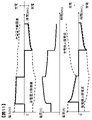
次に、本実施形態の効果について、図10、図11に基づき説明する。図10は、本発明の第1の実施形態を適用しない場合の上限電流による電池の電力、電圧および電流の変化の一例を示す図である。図10では、本実施形態で説明したような上限電流の設定方法を適用せずに、充電側上限電流および放電側上限電流をそれぞれ一定の値で設定し、電池を充電側上限電流で連続充電してから一定時間経過後に放電側上限電流で連続放電させた場合の、電力、電圧および電流の各波形例を示している。 Next, the effect of this embodiment will be described with reference to FIGS. 10 and 11. FIG. 10 is a diagram showing an example of changes in battery power, voltage, and current due to an upper limit current when the first embodiment of the present invention is not applied. In FIG. 10, the upper limit current on the charging side and the upper limit current on the discharging side are set to constant values without applying the upper limit current setting method as described in the present embodiment, and the battery is continuously charged with the upper limit current on the charging side. An example of each waveform of power, voltage, and current is shown when the battery is continuously discharged at the upper limit current on the discharge side after a certain period of time has elapsed.
図10に示すように、本実施形態の手法を適用せずに充電側上限電流および放電側上限電流をそれぞれ一定の値とした場合、最初の連続充電時には、充電開始からある程度の時間が経過すると、符号1001で示すように、拡散層のリチウムイオン濃度勾配に伴う抵抗の増大により電圧が上昇する。その結果、符号1003で示すように、電圧が上昇した分だけ電流値が小さくなってしまう。また、充電後の放電でも同様に、放電開始からある時間以上経過すると、符号1002で示すように、拡散層のリチウムイオン濃度勾配に伴う抵抗の増大により電圧が低下する。その結果、符号1004で示すように、電圧が低下した分だけ電流が大きくなり、上限電流を逸脱してしまっている。このような場合、充電側では電池に充電可能な電力が減少し、最悪の場合には、SOCが低いにも関わらず充電が出来なくなることが懸念される。一方で、放電側では逆に大電流が流れるため、電池の発熱や劣化の加速が懸念され、電池の性能を最大限活かすことが出来なくなる。
As shown in FIG. 10, when the upper limit current on the charging side and the upper limit current on the discharging side are set to constant values without applying the method of the present embodiment, a certain amount of time elapses from the start of charging during the first continuous charging. As shown by
図11は、本発明の第1の実施形態を適用した場合の上限電流による電池の電力、電圧および電流の変化の一例を示す図である。図11では、上述したような本実施形態による上限電流の設定方法に従って、拡散層におけるリチウムイオン濃度勾配を考慮して充電側上限電流および放電側上限電流を設定し、電池を充電側上限電流で連続充電してから一定時間経過後に放電側上限電流で連続放電させた場合の、電力、電圧および電流の各波形例を示している。 FIG. 11 is a diagram showing an example of changes in battery power, voltage, and current due to an upper limit current when the first embodiment of the present invention is applied. In FIG. 11, according to the method of setting the upper limit current according to the present embodiment as described above, the upper limit current on the charging side and the upper limit current on the discharging side are set in consideration of the lithium ion concentration gradient in the diffusion layer, and the battery is charged with the upper limit current on the charging side. An example of each waveform of power, voltage, and current is shown when the battery is continuously charged and then continuously discharged at the upper limit current on the discharge side after a certain period of time has elapsed.
図11に示すように、本実施形態の手法を適用して充電側上限電流および放電側上限電流をそれぞれ設定した場合、拡散層でのリチウムイオン濃度勾配に伴う抵抗の増大を抑制可能な上限電流値をリアルタイムに推定した結果に基づく電力で、電池の充放電が行われる。そのため、充電側、放電側ともに、拡散抵抗増大に伴う急峻な電圧変化を抑制して、電池を充放電することが可能となる。その結果、図10のような充電時の電圧上昇や放電時の電圧低下が発生することなく、その結果、充電性能の低下を防ぐとともに、放電時の発熱や劣化を抑制し、電池の性能を最大限活用することが可能となる。 As shown in FIG. 11, when the upper limit current on the charge side and the upper limit current on the discharge side are set by applying the method of the present embodiment, the upper limit current capable of suppressing the increase in resistance due to the lithium ion concentration gradient in the diffusion layer. The battery is charged and discharged with the electric power based on the result of estimating the value in real time. Therefore, both the charging side and the discharging side can charge and discharge the battery by suppressing a steep voltage change due to an increase in diffusion resistance. As a result, the voltage rise during charging and the voltage drop during discharging as shown in FIG. 10 do not occur, and as a result, the deterioration of charging performance is prevented, the heat generation and deterioration during discharging are suppressed, and the performance of the battery is improved. It will be possible to make the best use of it.
以上説明したように、本発明の第1の実施形態によれば、二次電池の電圧が急峻に変化する領域を回避しつつ、電池の入出力性能を最大限活用することが可能となる。 As described above, according to the first embodiment of the present invention, it is possible to make maximum use of the input / output performance of the battery while avoiding the region where the voltage of the secondary battery changes abruptly.
以上説明した本発明の第1の実施形態によれば、以下の作用効果を奏する。 According to the first embodiment of the present invention described above, the following effects are exhibited.
(1)組電池制御部150における上限電流演算部152は、二次電池である単電池111や組電池110に流れる電流、またはこれらの電池の電流と温度に基づいて、電池の電極と電解質との界面付近に形成される拡散層におけるリチウムイオン濃度勾配を推定する濃度勾配推定部1523と、このリチウムイオン濃度勾配に基づいて電池の上限電流値を決定する上限電流決定部1524とを備える。上限電流決定部1524は、リチウムイオン濃度勾配に応じた電池の過電圧が所定の範囲内となるように、上限電流値を決定する。このようにしたので、電極と電解質との界面付近に形成される拡散層におけるリチウムイオン濃度勾配によって生じる大電流領域での電池電圧の急峻な変化を考慮して、適切な上限電流値を設定することができる。
(1) The upper limit
(2)上限電流決定部1524は、電池の内部抵抗のうちリチウムイオン濃度勾配に応じた抵抗成分の割合が所定の範囲内となるように、上限電流値を決定する。このようにしたので、電池の過電圧が所定の範囲内となるような上限電流値を確実に決定することができる。
(2) The upper limit
(3)組電池制御部150における上限電流演算部152は、電池の電極と電解質との界面におけるリチウムイオン濃度を推定する界面濃度推定部1521と、拡散層の厚さを推定する拡散層推定部1522とを備える。濃度勾配推定部1523は、界面濃度推定部1521が推定した界面におけるリチウムイオン濃度と、拡散層推定部1522が推定した拡散層の厚さとに基づいて、リチウムイオン濃度勾配を推定する。このようにしたので、電池の電極と電解質との界面付近に形成される拡散層におけるリチウムイオン濃度勾配を確実に推定することができる。
(3) The upper limit
(4)組電池制御部150は、上限電流演算部152において上限電流決定部1524が決定した上限電流値に基づいて、上限電流通電時の電池の電圧を推定し、推定した電圧および上限電流値に基づいて、電池の充電可能電力および放電可能電力を推定する充放電可能電力演算部153を備える。このようにしたので、上限電流通電時の充電可能電力および放電可能電力をリアルタイムに推定することができる。
(4) The assembled
なお、以上説明した本発明の第1の実施形態では、上限電流決定部1524において、各電池の温度とリチウムイオン濃度勾配に基づき、電池の内部抵抗のうち拡散層でのリチウムイオン濃度勾配に応じた抵抗成分の割合が所定の範囲内となるように充電側上限電流値および放電側上限電流値を決定することで、電池の過電圧が所定の範囲内となるように制御する例を説明した。しかし、これ以外の方法で上限電流値を決定してもよい。例えば、電池の充放電電力がそれぞれ最大となるように充電側上限電流値および放電側上限電流値を決定することで、電池の過電圧が所定の範囲内となるように制御することもできる。なお、前述の図8で示したように、充放電を開始してからの通電時間が長くなるほど電池の抵抗が増加するため、この点を考慮して、電池の通電時間の経過に応じて充電側上限電流値および放電側上限電流値を低下させるようにしてもよい。このような方法でも、第1の実施形態で説明したのと同様の効果を得ることができる。
In the first embodiment of the present invention described above, the upper limit
<第2の実施形態>
次に、本発明の第2の実施形態について説明する。本実施形態では、電池の劣化を考慮して上限電流値を決定する例を説明する。なお、本実施形態に係る電池システムの構成は、組電池制御部150に替えて組電池制御部150aを有する点以外は、第1の実施形態で説明した図1の電池システム100と同様である。以下では、この組電池制御部150と150aの差分点を中心に、本実施形態の内容を説明する。<Second embodiment>
Next, a second embodiment of the present invention will be described. In this embodiment, an example of determining the upper limit current value in consideration of the deterioration of the battery will be described. The configuration of the battery system according to the present embodiment is the same as that of the
図12は、本発明の第2の実施形態に係る組電池制御部150aの機能構成を示す図である。本実施形態における組電池制御部150aは、図3の上限電流演算部152に替えて上限電流演算部152aを有しており、電池状態検知部151が演算した各電池のSOHRがこの上限電流演算部152aに入力される点以外は、第1の実施形態における組電池制御部150と同様の機能構成である。
FIG. 12 is a diagram showing a functional configuration of the assembled
上限電流演算部152aは、第1の実施形態における上限電流演算部152と同様に、各電池の電流と温度に基づき、各電池の充電側上限電流および放電側上限電流を演算して出力する。このとき上限電流演算部152aは、電池状態検知部151が演算した各電池のSOHRに応じた上限電流値の演算を実施することで、各電池の劣化状態に基づいて充電側上限電流および放電側上限電流を変化させるようにする。
Similar to the upper limit
以下では、図13、図14に基づき、電池の劣化による上限電流値の変化について説明する。図13は、電池の劣化に伴う電圧波形の変化を説明する図である。電池が劣化していない新品状態において、例えば図13(a)に示す電流波形で電池を連続的に放電させると、電池の電圧は図13(b)に示すように変化する。この電圧波形では、放電開始から時間t1が経過した符号1301に示すタイミング以降において、第1の実施形態で説明したように、拡散層でのリチウムイオンの濃度勾配による抵抗成分が急峻に大きくなることで、電池電圧が急峻に低下している。
Hereinafter, changes in the upper limit current value due to deterioration of the battery will be described with reference to FIGS. 13 and 14. FIG. 13 is a diagram illustrating changes in the voltage waveform due to deterioration of the battery. In a new state in which the battery has not deteriorated, for example, when the battery is continuously discharged with the current waveform shown in FIG. 13 (a), the voltage of the battery changes as shown in FIG. 13 (b). In this voltage waveform, after the timing indicated by
一方、電池が劣化した状態において、例えば図13(a)に示す電流波形で電池を連続的に放電させると、電池の電圧は図13(c)に示すように変化する。この電圧波形では、劣化に伴う電池の内部抵抗の上昇により、新品時に比べて電流通電時の電圧降下が大きくなっている。また、放電開始から時間t2(t1>t2)が経過した符号1302に示すタイミング以降において、拡散層でのリチウムイオンの濃度勾配による抵抗成分が急峻に大きくなることで、電池電圧が急峻に低下している。すなわち、新品状態のときよりも短い時間で、リチウムイオンの拡散に伴う抵抗成分の増加が生じていることが分かる。
On the other hand, when the battery is continuously discharged with the current waveform shown in FIG. 13 (a) in a deteriorated state, the voltage of the battery changes as shown in FIG. 13 (c). In this voltage waveform, the voltage drop when the current is applied is larger than that when the battery is new due to the increase in the internal resistance of the battery due to deterioration. Further, after the timing indicated by
図14は、本発明の第2の実施形態における上限電流マップの例を示す図である。図14の上図に示したグラフは、図9と同様に、拡散層のリチウムイオン濃度勾配と上限電流との関係を表しており、横軸はリチウムイオン濃度と拡散層の厚さとの比率(濃度勾配)を、縦軸は上限電流を表している。この図において、丸や四角で示した各点は実測値を表しており、これらの点の種類によって電池の劣化状態の違いを表している。このグラフから、濃度勾配が同じでも、電池の劣化が進むにつれて上限電流が低くなることが分かる。 FIG. 14 is a diagram showing an example of an upper limit current map according to the second embodiment of the present invention. The graph shown in the upper part of FIG. 14 shows the relationship between the lithium ion concentration gradient of the diffusion layer and the upper limit current, as in FIG. 9, and the horizontal axis is the ratio of the lithium ion concentration to the thickness of the diffusion layer (the ratio of the lithium ion concentration to the thickness of the diffusion layer (the horizontal axis). Concentration gradient), and the vertical axis represents the upper limit current. In this figure, each point indicated by a circle or a square represents an actually measured value, and a difference in the deterioration state of the battery is shown depending on the type of these points. From this graph, it can be seen that even if the concentration gradient is the same, the upper limit current decreases as the deterioration of the battery progresses.
一方、図14の下図に示した表は、上図のグラフから構築した上限電流マップの例である。この表では、第1の実施形態で説明したような、温度と濃度勾配を軸にして上限電流値が設定された上限電流マップが、さらに劣化状態ごとに、すなわちSOHRの値ごとに複数構築されている。 On the other hand, the table shown in the lower figure of FIG. 14 is an example of the upper limit current map constructed from the graph in the upper figure. In this table, as described in the first embodiment, a plurality of upper limit current maps in which the upper limit current value is set with respect to the temperature and concentration gradient are further constructed for each deterioration state, that is, for each SOHR value. ing.
図14で説明したような上限電流マップは、例えば記憶部180に格納される。なお図14では、近似曲線を直線で近似しているが、第1の実施形態で説明した図9と同様に、実験結果に対してよく近似できる近似曲線を求めて上限電流マップを作成してもよい。
The upper limit current map as described with reference to FIG. 14 is stored in, for example, the
図15は、本発明の第2の実施形態に係る上限電流演算部152aの制御ブロック図である。本実施形態における上限電流演算部152aは、図7の上限電流決定部1524に替えて上限電流決定部1524aを有しており、電池状態検知部151が演算した各電池のSOHRがこの上限電流決定部1524aに入力される点以外は、第1の実施形態における上限電流演算部152と同様の機能構成である。
FIG. 15 is a control block diagram of the upper limit
上限電流決定部1524aは、第1の実施形態における上限電流決定部1524と同様に、濃度勾配推定部1523が推定した拡散層のリチウムイオン濃度勾配に基づいて、各電池の充電側上限電流および放電側上限電流を決定する。このとき上限電流決定部1524aは、単電池管理部120から上限電流演算部152aに入力される各電池の温度およびSOHRと、濃度勾配推定部1523の演算結果とに基づき、図14で説明したような上限電流マップを参照して、充電側上限電流および放電側上限電流をそれぞれ演算して出力する。これにより、現在の電池の劣化状態で、電極と電解質との界面付近に形成される拡散層でのリチウムイオン濃度勾配に応じた電池の過電圧が所定の範囲内となるように、充電側上限電流および放電側上限電流をそれぞれ決定する。
Similar to the upper limit
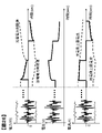
次に、本実施形態の効果について、図16、図17に基づき説明する。図16は、本発明の第2の実施形態を適用しない場合の上限電流による電池の電力、電圧および電流の変化の一例を示す図である。図16では、本実施形態で説明したような上限電流の設定方法を適用せずに、第1の実施形態で説明した方法に従って、劣化した電池に対して充電側上限電流および放電側上限電流をそれぞれ設定し、電池を充電側上限電流で連続充電してから一定時間経過後に放電側上限電流で連続放電させた場合の、電力、電圧および電流の各波形例を示している。 Next, the effects of this embodiment will be described with reference to FIGS. 16 and 17. FIG. 16 is a diagram showing an example of changes in battery power, voltage, and current due to an upper limit current when the second embodiment of the present invention is not applied. In FIG. 16, the upper limit current on the charging side and the upper limit current on the discharging side are set for the deteriorated battery according to the method described in the first embodiment without applying the upper limit current setting method as described in the present embodiment. An example of each waveform of power, voltage, and current is shown when each is set and the battery is continuously charged with the upper limit current on the charging side and then continuously discharged with the upper limit current on the discharging side after a certain period of time has elapsed.
図13で説明したように、電池が劣化していると、電池の通電を開始してから拡散層のリチウムイオン濃度勾配に伴う抵抗成分の増加が生じるまでの時間は、新品時よりも短くなる。そのため、図16に示すように、本実施形態の手法を適用せずに、すなわち電池の劣化状態を考慮せずに充電側上限電流および放電側上限電流を設定した場合、最初の連続充電時には、充電開始からある程度の時間が経過すると、符号1601で示すように、拡散層のリチウムイオン濃度勾配に伴う抵抗の増大により電圧が上昇する。その結果、符号1603で示すように、電圧が上昇した分だけ電流値が小さくなってしまう。また、充電後の放電でも同様に、放電開始からある時間以上経過すると、符号1602で示すように、拡散層のリチウムイオン濃度勾配に伴う抵抗の増大により電圧が低下する。その結果、符号1604で示すように、電圧が低下した分だけ電流が大きくなり、上限電流を逸脱してしまっている。このような場合、第1の実施形態で説明した充電側上限電流および放電側上限電流をそれぞれ一定の値とした場合と同様に、充電側では電池に充電可能な電力が減少し、最悪の場合には、SOCが低いにも関わらず充電が出来なくなることが懸念される。一方で、放電側では逆に大電流が流れるため、電池の発熱や劣化の加速が懸念され、電池の性能を最大限活かすことが出来なくなる。
As described with reference to FIG. 13, when the battery is deteriorated, the time from the start of energization of the battery to the increase of the resistance component due to the lithium ion concentration gradient of the diffusion layer becomes shorter than that of the new battery. .. Therefore, as shown in FIG. 16, when the charging side upper limit current and the discharging side upper limit current are set without applying the method of the present embodiment, that is, without considering the deterioration state of the battery, at the time of the first continuous charging, After a certain period of time has elapsed from the start of charging, the voltage rises due to the increase in resistance accompanying the lithium ion concentration gradient of the diffusion layer, as shown by
図17は、本発明の第2の実施形態を適用した場合の上限電流による電池の電力、電圧および電流の変化の一例を示す図である。図17では、上述したような本実施形態による上限電流の設定方法に従って、電池の劣化による抵抗の増大を考慮して充電側上限電流および放電側上限電流を設定し、電池を充電側上限電流で連続充電してから一定時間経過後に放電側上限電流で連続放電させた場合の、電力、電圧および電流の各波形例を示している。 FIG. 17 is a diagram showing an example of changes in battery power, voltage, and current due to an upper limit current when the second embodiment of the present invention is applied. In FIG. 17, according to the method of setting the upper limit current according to the present embodiment as described above, the upper limit current on the charging side and the upper limit current on the discharging side are set in consideration of the increase in resistance due to the deterioration of the battery, and the battery is set to the upper limit current on the charging side. An example of each waveform of power, voltage, and current is shown when the battery is continuously charged and then continuously discharged at the upper limit current on the discharge side after a certain period of time has elapsed.
図17に示すように、本実施形態の手法を適用して充電側上限電流および放電側上限電流をそれぞれ設定した場合、拡散層のリチウムイオン濃度勾配に伴う抵抗の増大を抑制可能な上限電流値を電池の劣化状態に応じてリアルタイムに推定した結果に基づく電力で、電池の充放電が行われる。そのため、充電側、放電側ともに、拡散抵抗増大に伴う急峻な電圧変化を抑制して、電池を充放電することが可能となる。その結果、電池が劣化している場合でも、図16のような充電時の電圧上昇や放電時の電圧低下が発生することなく、その結果、充電性能の低下を防ぐとともに、放電時の発熱や劣化を抑制し、電池の性能を最大限活用することが可能となる。 As shown in FIG. 17, when the upper limit current on the charge side and the upper limit current on the discharge side are set by applying the method of the present embodiment, the upper limit current value capable of suppressing the increase in resistance due to the lithium ion concentration gradient of the diffusion layer. The battery is charged and discharged with the electric power based on the result estimated in real time according to the deterioration state of the battery. Therefore, both the charging side and the discharging side can charge and discharge the battery by suppressing a steep voltage change due to an increase in diffusion resistance. As a result, even if the battery is deteriorated, the voltage rise during charging and the voltage drop during discharging as shown in FIG. 16 do not occur, and as a result, the charging performance is prevented from deteriorating, and heat generation during discharging is generated. It is possible to suppress deterioration and maximize the performance of the battery.
以上説明したように、本発明の第2の実施形態によれば、劣化した二次電池を使用した場合においても、二次電池の電圧が急峻に変化する領域を回避しつつ、電池の入出力性能を最大限活用することが可能となる。 As described above, according to the second embodiment of the present invention, even when a deteriorated secondary battery is used, the input / output of the battery is input / output while avoiding the region where the voltage of the secondary battery changes abruptly. It is possible to make the best use of performance.
以上説明した本発明の第2の実施形態によれば、第1の実施形態で説明したものに加えて、さらに以下の作用効果を奏する。 According to the second embodiment of the present invention described above, in addition to the one described in the first embodiment, the following effects are further exhibited.
(5)上限電流決定部1524aは、電池の劣化状態に基づいて上限電流値を変化させる。このようにしたので、劣化した二次電池を使用した場合においても、電池の過電圧が所定の範囲内となるような上限電流値を確実に決定することができる。
(5) The upper limit
<第3の実施形態>
次に、本発明の第3の実施形態について説明する。本実施形態では、第2の実施形態とは異なる、電解液中のリチウムイオン濃度(沖合いの濃度C*)が低下するような劣化モードをさらに考慮して上限電流値を決定する例を説明する。なお、本実施形態に係る電池システムの構成は、組電池制御部150に替えて組電池制御部150bを有する点以外は、第1の実施形態で説明した図1の電池システム100と同様である。以下では、この組電池制御部150と150bの差分点を中心に、本実施形態の内容を説明する。<Third embodiment>
Next, a third embodiment of the present invention will be described. In this embodiment, an example in which the upper limit current value is determined in consideration of a deterioration mode in which the lithium ion concentration (offshore concentration C * ) in the electrolytic solution is lowered, which is different from the second embodiment, will be described. .. The configuration of the battery system according to the present embodiment is the same as that of the
図18は、本発明の第3の実施形態に係る組電池制御部150bの機能構成を示す図である。本実施形態における組電池制御部150bは、イオン濃度推定部154が追加されている点と、図3の上限電流演算部152に替えて上限電流演算部152bを有しており、イオン濃度推定部154が演算した各電池のリチウムイオン濃度がこの上限電流演算部152bに入力される点以外は、第1の実施形態における組電池制御部150と同様の機能構成である。
FIG. 18 is a diagram showing a functional configuration of the assembled
イオン濃度推定部154は、各電池の電圧、温度およびSOCに基づき、各電池の電解液中のリチウムイオン濃度を推定する。本実施例で想定する劣化モードにより、電解液中のリチウムイオンが減少した電池に対しては、イオン濃度推定部154により、正常状態のものよりも低いリチウムイオン濃度が推定される。なお、本実施例で想定する劣化モード(沖合いのリチウムイオン濃度の低下)については、後述する。
The ion
上限電流演算部152bは、第1の実施形態における上限電流演算部152と同様に、各電池の電流と温度に基づき、各電池の充電側上限電流および放電側上限電流を演算して出力する。このとき上限電流演算部152bは、イオン濃度推定部154が推定した各電池のリチウムイオン濃度に応じた上限電流値の演算を実施することで、各電池のリチウムイオン濃度の変化に基づいて充電側上限電流および放電側上限電流を変化させるようにする。
Similar to the upper limit
以下では、図19、図20に基づき、本実施例で想定している劣化モード(沖合いのリチウムイオン濃度の低下)と上限電流値の変化について説明する。図19は、リチウムイオン濃度の低下による劣化モードを説明する図である。特に低温時において、大きな電流値が継続的に流れるような過剰な充放電を行うと、充放電反応とは異なる副反応が生じることにより、電解液中のリチウムイオンが減少する。このとき、劣化のない正常状態でのリチウムイオン濃度がC* 0であったとすると、劣化によりリチウムイオン濃度がC* 0からC* 1(C* 0>C* 1)へと変化する。こうした劣化モードが生じた場合に、拡散層の厚さδが正常状態から変化しないとすると、図19に示すように、拡散層におけるリチウムイオン濃度勾配が小さくなる。そのため、劣化のない正常状態よりも、リチウムイオンの拡散過程が律速となる段階に入りやすくなることが想定される。Hereinafter, the deterioration mode (decrease in offshore lithium ion concentration) and the change in the upper limit current value assumed in this embodiment will be described with reference to FIGS. 19 and 20. FIG. 19 is a diagram illustrating a deterioration mode due to a decrease in lithium ion concentration. Especially at low temperatures, if an excessive charge / discharge is performed so that a large current value continuously flows, a side reaction different from the charge / discharge reaction occurs, and the lithium ions in the electrolytic solution decrease. At this time, if the lithium ion concentration in the normal state without deterioration is C * 0 , the lithium ion concentration changes from C * 0 to C * 1 (C * 0 > C * 1 ) due to the deterioration. Assuming that the thickness δ of the diffusion layer does not change from the normal state when such a deterioration mode occurs, the lithium ion concentration gradient in the diffusion layer becomes smaller as shown in FIG. Therefore, it is assumed that it is easier to enter the stage where the diffusion process of lithium ions becomes rate-determining than in the normal state without deterioration.
図20は、リチウムイオン濃度の低下に伴う電圧波形の変化を説明する図である。リチウムイオン濃度が低下していない新品状態において、例えば図20(a)に示す電流波形で電池を連続的に放電させると、電池の電圧は図20(b)に示すように変化する。この電圧波形では、放電開始から時間t1が経過した符号2001に示すタイミング以降において、第1の実施形態で説明したように、拡散層でのリチウムイオンの濃度勾配による抵抗成分が急峻に大きくなることで、電池電圧が急峻に低下している。
FIG. 20 is a diagram illustrating a change in the voltage waveform with a decrease in the lithium ion concentration. In a new state in which the lithium ion concentration has not decreased, for example, when the battery is continuously discharged with the current waveform shown in FIG. 20 (a), the voltage of the battery changes as shown in FIG. 20 (b). In this voltage waveform, after the timing indicated by
一方、劣化によりリチウムイオン濃度が低下した状態において、例えば図20(a)に示す電流波形で電池を連続的に放電させると、電池の電圧は図20(c)に示すように変化する。この電圧波形では、リチウムイオン濃度の低下に伴ってリチウムイオンの拡散過程が律速となる段階に入りやすくなることで、放電開始から時間t3(t1>t3)が経過した符号2002に示すタイミング以降において、拡散層でのリチウムイオンの濃度勾配による抵抗成分が急峻に大きくなり、電池電圧が急峻に低下している。すなわち、新品状態のときよりも短い時間で、リチウムイオンの拡散に伴う抵抗成分の増加が生じていることが分かる。
On the other hand, when the battery is continuously discharged with the current waveform shown in FIG. 20 (a) in a state where the lithium ion concentration is lowered due to deterioration, the voltage of the battery changes as shown in FIG. 20 (c). In this voltage waveform, it becomes easier to enter the stage where the diffusion process of lithium ions becomes rate-determining as the lithium ion concentration decreases, so that after the timing indicated by
そこで本実施形態では、組電池制御部150bにイオン濃度推定部154を設けることで、リチウムイオン濃度の低下を検出する機能を組電池制御部150bに追加した。これにより、リチウムイオン濃度が低下した場合でも、上述したリチウムイオンの拡散過程が律速となる段階に入りやすくなるモードに陥るのを回避するように、上限電流を設定して電池を制御する。
Therefore, in the present embodiment, by providing the ion
図21は、本発明の第3の実施形態に係る上限電流演算部152bの制御ブロック図である。本実施形態における上限電流演算部152bは、図7の界面濃度推定部1521に替えて界面濃度推定部1521bを有しており、イオン濃度推定部154が推定した各電池のリチウムイオン濃度がこの界面濃度推定部1521bに入力される点以外は、第1の実施形態における上限電流演算部152と同様の機能構成である。
FIG. 21 is a control block diagram of the upper limit
界面濃度推定部1521bは、第1の実施形態における界面濃度推定部1521と同様に、電流検知部130や単電池管理部120から上限電流演算部152bに入力される各電池の電流および温度に基づき、前述の式(4)により、充電または放電時における電極と電解質との界面のリチウムイオン濃度を推定する。このとき界面濃度推定部1521bは、式(4)の右辺の第一項におけるC*の値を、イオン濃度推定部154から入力されるリチウムイオン濃度に置き換える。これにより、電池の劣化によって電解液全体のリチウムイオン濃度が低下した場合には、その劣化状態に対応した界面のリチウムイオン濃度を推定する。なお、第1の実施形態と同様に、式(4)において拡散定数D(T)の値を温度Tに関わらず一定であると仮定すれば、界面濃度推定部1521bにおいて、各電池の電流とリチウムイオン濃度のみに基づいて界面のリチウムイオン濃度を算出することも可能である。Similar to the interface
図22は、本発明の第3の実施形態に係るイオン濃度推定部154の制御ブロック図である。イオン濃度推定部154は、電圧差実効値演算部1541、電圧差閾値演算部1542、電圧差比率演算部1543、およびイオン濃度演算部1544から構成される。
FIG. 22 is a control block diagram of the ion
電圧差実効値演算部1541は、電圧およびSOCを入力として、予め設定した所定の時間窓における電圧差実効値を演算する。具体的には、電圧差実効値演算部1541は、例えば以下の式(7)~(9)に従って、電圧差実効値ΔVRMSを演算する。なお、式(7)中のOCVは、入力されたSOCに基づき、予め設定されたSOCとOCVの対応関係から算出することができる。The voltage difference effective

式(7)~(9)において、ΔV(t)はCCVとOCVの電圧差[V]を表しており、これは電池の過電圧に相当する。また、ΔVFilter(t)はΔV2(t)の一次遅れフィルタ適用結果[V2]、tsは制御周期[sec]、Twは時間窓[sec]、ΔVRMS(t)は電圧差実効値[V]をそれぞれ表している。In the equations (7) to (9), ΔV (t) represents the voltage difference [V] between CCV and OCV, which corresponds to the overvoltage of the battery. In addition, ΔV Filter (t) is the result of applying the first-order lag filter of ΔV 2 (t) [V 2 ], ts is the control cycle [sec], Tw is the time window [sec], and ΔV RMS (t) is the voltage difference effective value. Represents [V] respectively.
電圧差閾値演算部1542は、温度を入力として、電圧差実効値演算部1541が演算する電圧差実効値に対する閾値を演算する。この閾値は、電圧差実効値に対して電池内でリチウムイオン濃度が低下するか否かの基準となるものであり、電圧差実効値が算出された時間窓の長さや温度に応じて決定される。具体的には、電圧差閾値演算部1542は、例えば予め記憶部180に格納されたマップ情報を用いて、閾値を決定する。このマップ情報は、図20(c)で説明したような現象が起こらないような電圧差実効値の条件を表すものであり、予め実験により抽出された時間窓および温度と電圧差実効値との関係に基づいて作成される。
The voltage difference
図23は、電圧差閾値演算部1542により演算される閾値の例を示す図である。この図では、時間窓Twが長いほど、また温度が低いほど、電圧差閾値演算部1542が演算する閾値(CCVとOCVの電圧差に対する制限値)が小さくなっている。つまり、電池の充放電時間が長く、また電池の温度が低いほど、上限電流に対する制限が厳しくなるように閾値が設定されている。
FIG. 23 is a diagram showing an example of a threshold value calculated by the voltage difference threshold
電圧差比率演算部1543は、電圧差実効値演算部1541が出力する電圧差実効値と、電圧差閾値演算部1542が出力する閾値との比率である電圧差比率を演算する。電圧差比率演算部1543は、例えば以下の式(10)により、電圧差比率を演算して出力する。
The voltage difference
![]()
![]()
式(10)において、ΔVthresh(t)は電圧差実効値ΔVRMS(t)に対する制限閾値[V]、ΔVRatio(t)は電圧差比率[%]をそれぞれ表している。なお、電圧差比率ΔVRatio(t)は、電池の負荷状態に対する判定指標である負荷判定指標に相当する。In equation (10), ΔV thresh (t) represents the limiting threshold value [V] for the voltage difference effective value ΔV RMS (t), and ΔV Ratio (t) represents the voltage difference ratio [%]. The voltage difference ratio ΔV Ratio (t) corresponds to a load judgment index which is a judgment index for the load state of the battery.
図20(c)で説明したような現象は、時間窓の長い、つまり、充放電が長期間継続的に続いている条件にて発生しやすい。そのため、電圧差実効値演算部1541や電圧差閾値演算部1542では、長めの時間窓を予め設定しておくことが望ましい。すなわち、リチウムイオン濃度の低下は、温度が小さく、かつ、長時間の連続的な充放電時に起こりやすいため、長めの時間窓を予め設定しておくことで、上限電流に対する制限を厳しくし、上記の現象を確実に防止することができる。
The phenomenon as described in FIG. 20 (c) is likely to occur under the condition that the time window is long, that is, the charging / discharging continues for a long period of time. Therefore, it is desirable that the voltage difference effective
イオン濃度演算部1544は、電圧差比率演算部1543が演算した電圧差比率をもとに、リチウムイオン濃度を推定し出力する。イオン濃度演算部1544は、例えば予め記憶部180に格納された電圧差比率とリチウムイオン濃度との関係を用いて、電圧差比率の演算結果に対応するリチウムイオン濃度を推定する。
The ion
図24は、電圧差比率とリチウムイオン濃度との関係の一例を示す図である。図24では、横軸に電圧差比率を、縦軸にリチウムイオン濃度を表している。図24に示した関係では、電圧差比率がある一定の閾値Th1を超えたところからリチウムイオン濃度が減少し始め、閾値Th2で0となる。 FIG. 24 is a diagram showing an example of the relationship between the voltage difference ratio and the lithium ion concentration. In FIG. 24, the horizontal axis represents the voltage difference ratio and the vertical axis represents the lithium ion concentration. In the relationship shown in FIG. 24, the lithium ion concentration starts to decrease when the voltage difference ratio exceeds a certain threshold value Th1, and becomes 0 at the threshold value Th2.
イオン濃度推定部154は、以上説明したようにして、電池の劣化状態に応じたリチウムイオン濃度を演算する。イオン濃度推定部154により演算されたリチウムイオン濃度は、上限電流演算部152bに入力される。
As described above, the ion
次に、本実施形態の効果について、図25、図26に基づき説明する。図25は、本発明の第3の実施形態を適用しない場合の上限電流による電池の電力、電圧および電流の変化の一例を示す図である。図25では、本実施形態で説明したような上限電流の設定方法を適用せずに、第1、第2の実施形態で説明した方法に従って、リチウムイオン濃度の低下が発生するような過剰な充放電が行われて劣化した電池に対して充電側上限電流および放電側上限電流をそれぞれ設定し、電池を充電側上限電流で連続充電してから一定時間経過後に放電側上限電流で連続放電させた場合の、電力、電圧および電流の各波形例を示している。 Next, the effect of this embodiment will be described with reference to FIGS. 25 and 26. FIG. 25 is a diagram showing an example of changes in battery power, voltage, and current due to an upper limit current when the third embodiment of the present invention is not applied. In FIG. 25, the upper limit current setting method as described in the present embodiment is not applied, and the lithium ion concentration is excessively charged according to the methods described in the first and second embodiments. The charging side upper limit current and the discharging side upper limit current were set for the battery that had been discharged and deteriorated, and the battery was continuously charged with the charging side upper limit current and then continuously discharged with the discharging side upper limit current after a certain period of time. An example of each waveform of power, voltage, and current is shown.
図20で説明したように、リチウムイオン濃度が低下していると、電池の通電を開始してから拡散層のリチウムイオン濃度勾配に伴う抵抗成分の増加が生じるまでの時間は、新品時よりも短くなる。そのため、図25に示すように、本実施形態の手法を適用せずに、すなわちリチウムイオン濃度の低下を考慮せずに充電側上限電流および放電側上限電流を設定した場合、これらに対応する充電電力制限値または放電電力制限値に満たない電力で行われる未制限時の充放電では、リチウムイオン濃度の低下が発生したことを検出できない。したがって、その後に充電電力制限値で行われる最初の連続充電時には、充電開始からある程度の時間が経過すると、符号2501で示すように、拡散層のリチウムイオン濃度勾配に伴う抵抗の増大により電圧が上昇する。その結果、符号2503で示すように、電圧が上昇した分だけ電流値が小さくなってしまう。また、充電後に放電電力制限値で行われる連続放電でも同様に、放電開始からある時間以上経過すると、符号2502で示すように、拡散層のリチウムイオン濃度勾配に伴う抵抗の増大により電圧が低下する。その結果、符号2504で示すように、電圧が低下した分だけ電流が大きくなり、上限電流を逸脱してしまっている。このような場合、第1の実施形態で説明した充電側上限電流および放電側上限電流をそれぞれ一定の値とした場合や、第2の実施形態で説明した電池の劣化を考慮せずに充電側上限電流および放電側上限電流を設定した場合と同様に、充電側では電池に充電可能な電力が減少し、最悪の場合には、SOCが低いにも関わらず充電が出来なくなることが懸念される。一方で、放電側では逆に大電流が流れるため、電池の発熱や劣化の加速が懸念され、電池の性能を最大限活かすことが出来なくなる。
As described with reference to FIG. 20, when the lithium ion concentration is low, the time from the start of energization of the battery to the increase of the resistance component due to the lithium ion concentration gradient of the diffusion layer is longer than that of the new battery. It gets shorter. Therefore, as shown in FIG. 25, when the charge side upper limit current and the discharge side upper limit current are set without applying the method of the present embodiment, that is, without considering the decrease in the lithium ion concentration, the charge corresponding to these is set. Unlimited charging / discharging performed with power less than the power limit value or discharge power limit value cannot detect that a decrease in lithium ion concentration has occurred. Therefore, at the time of the first continuous charging performed at the charging power limit value after that, when a certain time elapses from the start of charging, the voltage rises due to the increase in resistance due to the lithium ion concentration gradient of the diffusion layer, as shown by
図26は、本発明の第3の実施形態を適用した場合の上限電流による電池の電力、電圧および電流の変化の一例を示す図である。図26では、上述したような本実施形態による上限電流の設定方法に従って、未制限時の充放電によるリチウムイオン濃度の低下を検出し、これを反映して充電側上限電流および放電側上限電流を設定し、電池を充電側上限電流で連続充電してから一定時間経過後に放電側上限電流で連続放電させた場合の、電力、電圧および電流の各波形例を示している。 FIG. 26 is a diagram showing an example of changes in battery power, voltage, and current due to an upper limit current when the third embodiment of the present invention is applied. In FIG. 26, according to the method of setting the upper limit current according to the present embodiment as described above, a decrease in the lithium ion concentration due to unrestricted charging / discharging is detected, and the charging side upper limit current and the discharging side upper limit current are reflected to reflect this. An example of each waveform of power, voltage, and current is shown when the battery is continuously charged with the upper limit current on the charging side and then continuously discharged with the upper limit current on the discharging side after a certain period of time has elapsed.
図26に示すように、本実施形態の手法を適用して充電側上限電流および放電側上限電流をそれぞれ設定した場合、拡散層のリチウムイオン濃度勾配に伴う抵抗の増大を抑制可能な上限電流値をリチウムイオン濃度の低下状態に応じてリアルタイムに推定した結果に基づく電力で、電池の充放電が行われる。そのため、充電側、放電側ともに、拡散抵抗増大に伴う急峻な電圧変化を抑制して、電池を充放電することが可能となる。その結果、電池のリチウムイオン濃度が低下している場合でも、図25のような充電時の電圧上昇や放電時の電圧低下が発生することなく、その結果、充電性能の低下を防ぐとともに、放電時の発熱や劣化を抑制し、電池の性能を最大限活用することが可能となる。 As shown in FIG. 26, when the upper limit current on the charging side and the upper limit current on the discharging side are set by applying the method of the present embodiment, the upper limit current value capable of suppressing the increase in resistance due to the lithium ion concentration gradient of the diffusion layer. The battery is charged and discharged with the power based on the result estimated in real time according to the state of decrease in the lithium ion concentration. Therefore, both the charging side and the discharging side can charge and discharge the battery by suppressing a steep voltage change due to an increase in diffusion resistance. As a result, even when the lithium ion concentration of the battery is low, the voltage rise during charging and the voltage drop during discharging as shown in FIG. 25 do not occur, and as a result, the charging performance is prevented from deteriorating and the battery is discharged. It is possible to suppress heat generation and deterioration during time and maximize the performance of the battery.
以上説明したように、本発明の第3の実施形態によれば、劣化によりリチウムイオン濃度が低下した二次電池を使用した場合においても、二次電池の電圧が急峻に変化する領域を回避しつつ、電池の入出力性能を最大限活用することが可能となる。 As described above, according to the third embodiment of the present invention, even when a secondary battery whose lithium ion concentration has decreased due to deterioration is used, a region where the voltage of the secondary battery changes abruptly is avoided. At the same time, it is possible to make the best use of the input / output performance of the battery.
なお、上記の実施形態では、イオン濃度推定部154が行う演算処理について、前述の式(7)、(8)により、過電圧(CCV-OCV)の二乗値に対して一次遅れフィルタを施し、その結果を用いて式(9)、(10)により、電圧差比率を演算する例を説明した。しかしながら、イオン濃度推定部154が行う演算処理はこれに限定されず、例えば過電圧の代わりに電流の二乗値を用いてもよい。この場合、電圧差閾値演算部1542により演算されて式(10)で用いられる閾値についても、図23に例示したような電圧差の実効値に対する閾値に替えて、電流の実効値に対応した閾値とすることが好ましい。これにより、過電圧ベースでの制御の代替として、電流ベースでの制御を利用できる。すなわち、イオン濃度推定部154は、電池の過電圧または電流の実効値に基づいて、リチウムイオン濃度を推定することが可能である。
In the above embodiment, the arithmetic processing performed by the ion
また、本実施形態では、予め実施された実験結果をベースに、リチウムイオン濃度の低下を簡易的に検知する手法について述べたが、本発明はこれに限定されるものではない。例えば、リチウムイオンの副反応に伴うリチウム化合物の生成をモデル化して、電池内のリチウムイオン量の低下を推定し、その推定結果を式(4)へ反映することで、電極と電解質との界面におけるリチウムイオン濃度を推定してもよい。 Further, in the present embodiment, a method for simply detecting a decrease in the lithium ion concentration based on the results of experiments carried out in advance has been described, but the present invention is not limited thereto. For example, by modeling the formation of a lithium compound due to a side reaction of lithium ions, estimating the decrease in the amount of lithium ions in the battery, and reflecting the estimation result in the equation (4), the interface between the electrode and the electrolyte The lithium ion concentration in the above may be estimated.
以上説明した本発明の第3の実施形態によれば、第1の実施形態で説明したものに加えて、さらに以下の作用効果を奏する。 According to the third embodiment of the present invention described above, in addition to the one described in the first embodiment, the following effects are further exhibited.
(6)組電池制御部150bは、電池のリチウムイオン濃度を推定するイオン濃度推定部154を備える。上限電流演算部152bにおいて、上限電流決定部1524は、イオン濃度推定部154が推定したリチウムイオン濃度の変化に基づいて上限電流値を変化させる。このようにしたので、劣化によりリチウムイオン濃度が低下した二次電池を使用した場合においても、電池の過電圧が所定の範囲内となるような上限電流値を確実に決定することができる。
(6) The assembled
(7)イオン濃度推定部154は、電池の過電圧または電流の実効値に基づいて電池のリチウムイオン濃度を推定する。このようにしたので、過剰な充放電が行われて電池のリチウムイオン濃度が低下した場合に、これを確実に検知することができる。
(7) The ion
<第4の実施形態>
次に、本発明の第4の実施形態について説明する。本実施形態では、第3の実施形態とは異なる方法により、リチウムイオン濃度が低下した電池に対する充放電制御を行う例を説明する。なお、本実施形態に係る電池システムの構成は、組電池制御部150に替えて組電池制御部150cを有する点以外は、第1の実施形態で説明した図1の電池システム100と同様である。以下では、この組電池制御部150と150cの差分点を中心に、本実施形態の内容を説明する。<Fourth Embodiment>
Next, a fourth embodiment of the present invention will be described. In this embodiment, an example of performing charge / discharge control for a battery having a reduced lithium ion concentration by a method different from that of the third embodiment will be described. The configuration of the battery system according to the present embodiment is the same as that of the
図27は、本発明の第4の実施形態に係る組電池制御部150cの機能構成を示す図である。本実施形態における組電池制御部150cは、制限率設定部155が追加されている点と、図3の充放電可能電力演算部153に替えて充放電可能電力演算部153cを有しており、制限率設定部155が設定した制限率がこの充放電可能電力演算部153cに入力される点以外は、第1の実施形態における組電池制御部150と同様の機能構成である。
FIG. 27 is a diagram showing a functional configuration of the assembled battery control unit 150c according to the fourth embodiment of the present invention. The assembled battery control unit 150c in the present embodiment has a point that the limit
制限率設定部155は、各電池の電圧、温度およびSOCに基づき、各電池の電解液中のリチウムイオン濃度の変化に応じた制限率を設定する。なお、制限率設定部155が設定する制限率には、第3の実施形態においてイオン濃度推定部154が推定するリチウムイオン濃度と同様に、各電池の劣化状態が反映される。すなわち、劣化によって電解液中のリチウムイオンが減少した電池に対しては、制限率設定部155により、正常状態のものとは異なる制限率が設定される。
The limit
充放電可能電力演算部153cは、第1の実施形態における充放電可能電力演算部153と同様に、電池状態検知部151が演算した各電池のSOCおよびSOHRと、組電池制御部150に入力される各電池の温度と、上限電流演算部152が演算した各電池の充電側上限電流および放電側上限電流をもとに、各電池の充電可能電力および放電可能電力を演算して出力する。このとき充放電可能電力演算部153cは、制限率設定部155が設定した制限率に基づき、各電池のリチウムイオン濃度の変化に応じて充電可能電力および放電可能電力を変化させるようにする。
The charge / discharge possible
図28は、本発明の第4の実施形態に係る制限率設定部155の制御ブロック図である。制限率設定部155は、電圧差実効値演算部1541、電圧差閾値演算部1542、電圧差比率演算部1543、および制限率演算部1554から構成される。なお、電圧差実効値演算部1541、電圧差閾値演算部1542および電圧差比率演算部1543については、第3の実施形態において図22に示したイオン濃度推定部154が有するものとそれぞれ同様である。
FIG. 28 is a control block diagram of the limit
制限率演算部1554は、電圧差比率演算部1543が演算した電圧差比率をもとに、充電可能電力および放電可能電力に対する制限率を設定する。制限率演算部1554は、例えば予め記憶部180に格納された電圧差比率と制限率との関係を用いて、電圧差比率の演算結果に対応する制限率kを演算する。
The limit
図29は、電圧差比率と制限率との関係の一例を示す図である。図29では、横軸に電圧差比率を、縦軸に制限率を表している。図29に示した関係では、電圧差比率がある一定の閾値Th1を超えたところから、制限率の値が小さくなり始めることで充電可能電力および放電可能電力に対する制限が厳しくなっている。また、閾値Th2で制限率が0となることで、充電および放電が禁止される。 FIG. 29 is a diagram showing an example of the relationship between the voltage difference ratio and the limit rate. In FIG. 29, the horizontal axis represents the voltage difference ratio and the vertical axis represents the limit rate. In the relationship shown in FIG. 29, the limit on the rechargeable power and the dischargeable power becomes stricter as the value of the limit factor starts to decrease from the point where the voltage difference ratio exceeds a certain threshold value Th1. Further, when the limit rate becomes 0 at the threshold value Th2, charging and discharging are prohibited.
制限率設定部155は、以上説明したようにして、劣化によりリチウムイオン濃度が低下している場合は、そのリチウムイオン濃度に応じた制限率を設定する。制限率設定部155により設定された制限率kは、充放電可能電力演算部153cへ入力される。
As described above, when the lithium ion concentration is lowered due to deterioration, the limit
充放電可能電力演算部153cは、例えば以下の式(11)、(12)により、制限率設定部155から入力される制限率kを充電可能電力と放電可能電力にそれぞれ乗算することで、充電可能電力および放電可能電力を変化させる。なお、式(11)または(12)を用いて、充電可能電力または放電可能電力のいずれか一方のみを変化させてもよい。
The charge / discharge rechargeable

以上説明したように、本実施形態によれば、電池内のリチウムイオン濃度の変化に基づいて充電可能電力または放電可能電力を変化させる。その結果、第3の実施形態において図25、26で説明したのと同様の効果を得ることができるため、劣化によりリチウムイオン濃度が低下した二次電池を使用した場合においても、二次電池の電圧が急峻に変化する領域を回避しつつ、電池の入出力性能を最大限活用することが可能となる。 As described above, according to the present embodiment, the rechargeable power or the dischargeable power is changed based on the change in the lithium ion concentration in the battery. As a result, the same effect as described with reference to FIGS. 25 and 26 can be obtained in the third embodiment. Therefore, even when a secondary battery having a reduced lithium ion concentration due to deterioration is used, the secondary battery It is possible to make the best use of the input / output performance of the battery while avoiding the region where the voltage changes suddenly.
なお、本実施形態でも第3の実施形態と同様に、制限率設定部155が行う演算処理において、過電圧の代わりに電流の二乗値を用いてもよい。
In this embodiment as well as in the third embodiment, the square value of the current may be used instead of the overvoltage in the arithmetic processing performed by the limit
以上説明した本発明の第4の実施形態によれば、第1の実施形態で説明したものに加えて、さらに以下の作用効果を奏する。 According to the fourth embodiment of the present invention described above, in addition to the one described in the first embodiment, the following effects are further exhibited.
(8)充放電可能電力演算部153cは、電池のリチウムイオン濃度の変化に応じて充電可能電力または放電可能電力を変化させる。このようにしたので、劣化によりリチウムイオン濃度が低下した二次電池を使用した場合においても、電池の過電圧が所定の範囲内となるように、上限電流通電時の充電可能電力または放電可能電力を適切に定めることができる。
(8) The charge / discharge rechargeable
(9)組電池制御部150cは、電池の過電圧または電流の実効値に基づいて電池のリチウムイオン濃度の変化に応じた制限率を設定する制限率設定部155を備える。充放電可能電力演算部153cは、制限率設定部155が設定した制限率に基づいて、充電可能電力または放電可能電力を変化させる。このようにしたので、過剰な充放電が行われて電池のリチウムイオン濃度が低下した場合に、これに応じた充電可能電力または放電可能電力を確実に定めることができる。
(9) The assembled battery control unit 150c includes a limit
なお、以上説明した各実施形態では、二次電池としてリチウムイオン電池を用いた場合に、電極と電解質との界面付近に形成される拡散層におけるリチウムイオン濃度に基づいて充放電制御を行う場合の例を説明したが、他の二次電池を用いた場合にも、同様の充放電制御が可能である。すなわち、リチウムイオンに限らず、他の任意のイオンに関して、電極と電解質との界面付近に形成される拡散層におけるイオン濃度に基づいて充放電制御を行う場合に、本発明を適用可能である。 In each of the above-described embodiments, when a lithium ion battery is used as the secondary battery, charge / discharge control is performed based on the lithium ion concentration in the diffusion layer formed near the interface between the electrode and the electrolyte. Although an example has been described, the same charge / discharge control can be performed when another secondary battery is used. That is, the present invention can be applied not only to lithium ions but also to other arbitrary ions when charge / discharge control is performed based on the ion concentration in the diffusion layer formed near the interface between the electrode and the electrolyte.
なお、以上説明した各実施形態や各種変形例はあくまで一例であり、発明の特徴が損なわれない限り、本発明はこれらの内容に限定されるものではない。また、上記の各実施形態は、任意に組み合わせて使用することもできる。さらに、上記では種々の実施形態や変形例を説明したが、本発明はこれらの内容に限定されるものではない。本発明の技術的思想の範囲内で考えられるその他の態様も本発明の範囲内に含まれる。 It should be noted that the above-described embodiments and various modifications are merely examples, and the present invention is not limited to these contents as long as the features of the invention are not impaired. Further, each of the above embodiments can be used in any combination. Further, although various embodiments and modifications have been described above, the present invention is not limited to these contents. Other aspects considered within the scope of the technical idea of the present invention are also included within the scope of the present invention.
100:電池システム
110:組電池
111:単電池
112:単電池群
120:単電池管理部
121:単電池制御部
122:電圧検出回路
123:制御回路
124:信号入出力回路
125:温度検知部
130:電流検知部
140:電圧検知部
150,150a,150b,150c:組電池制御部
151:電池状態検知部
152,152a,152b:上限電流演算部
153,153c:充放電可能電力演算部
154:イオン濃度推定部
155:制限率設定部
160:信号通信手段
170:絶縁素子
180:記憶部
200:車両制御部
300~330:リレー
400:インバータ
410:モータジェネレータ
1521,1521b:界面濃度推定部
1522:拡散層推定部
1523:濃度勾配推定部
1524,1524a:上限電流決定部
1541:電圧差実効値演算部
1542:電圧差閾値演算部
1543:電圧差比率演算部
1544:イオン濃度演算部
1554:制限率演算部100: Battery system 110: Combined battery 111: Single battery 112: Single battery group 120: Single battery management unit 121: Single battery control unit 122: Voltage detection circuit 123: Control circuit 124: Signal input / output circuit 125: Temperature detection unit 130 : Current detection unit 140:
Claims (11)
前記イオン濃度勾配に基づいて前記二次電池の上限電流値を決定する上限電流決定部と、を備え、
前記上限電流決定部は、前記イオン濃度勾配に応じた前記二次電池の過電圧が所定の範囲内となるように、前記上限電流値を決定する電池制御装置。A concentration gradient estimation unit that estimates the ion concentration gradient in the diffusion layer formed near the interface between the electrode of the secondary battery and the electrolyte based on the current flowing through the secondary battery or the current and the temperature of the secondary battery. When,
A unit for determining an upper limit current for determining an upper limit current value of the secondary battery based on the ion concentration gradient is provided.
The upper limit current determining unit is a battery control device that determines the upper limit current value so that the overvoltage of the secondary battery according to the ion concentration gradient is within a predetermined range.
前記上限電流決定部は、前記二次電池の内部抵抗のうち前記イオン濃度勾配に応じた抵抗成分の割合が所定の範囲内となるように、前記上限電流値を決定する電池制御装置。In the battery control device according to claim 1,
The upper limit current determining unit is a battery control device that determines the upper limit current value so that the ratio of the resistance component corresponding to the ion concentration gradient to the internal resistance of the secondary battery is within a predetermined range.
前記上限電流決定部は、前記二次電池の充電電力または放電電力が最大となるように、前記上限電流値を決定する電池制御装置。In the battery control device according to claim 1,
The upper limit current determining unit is a battery control device that determines the upper limit current value so that the charging power or the discharging power of the secondary battery is maximized.
前記上限電流決定部は、前記二次電池の通電時間の経過に応じて前記上限電流値を低下させるように、前記上限電流値を決定する電池制御装置。In the battery control device according to claim 3,
The upper limit current determining unit is a battery control device that determines the upper limit current value so as to reduce the upper limit current value according to the passage of the energization time of the secondary battery.
前記界面におけるイオン濃度を推定する界面濃度推定部と、
前記拡散層の厚さを推定する拡散層推定部と、を備え、
前記濃度勾配推定部は、前記界面濃度推定部が推定した前記界面におけるイオン濃度と、前記拡散層推定部が推定した前記拡散層の厚さとに基づいて、前記イオン濃度勾配を推定する電池制御装置。In the battery control device according to claim 1,
An interface concentration estimation unit that estimates the ion concentration at the interface,
A diffusion layer estimation unit for estimating the thickness of the diffusion layer is provided.
The concentration gradient estimation unit is a battery control device that estimates the ion concentration gradient based on the ion concentration at the interface estimated by the interface concentration estimation unit and the thickness of the diffusion layer estimated by the diffusion layer estimation unit. ..
前記上限電流決定部が決定した前記上限電流値に基づいて、上限電流通電時の前記二次電池の電圧を推定し、推定した前記電圧および前記上限電流値に基づいて、前記二次電池の充電可能電力および放電可能電力を推定する充放電可能電力演算部を備える電池制御装置。In the battery control device according to any one of claims 1 to 5.
The voltage of the secondary battery when the upper limit current is energized is estimated based on the upper limit current value determined by the upper limit current determination unit, and the secondary battery is charged based on the estimated voltage and the upper limit current value. A battery control device including a charge / dischargeable power calculation unit that estimates possible power and dischargeable power.
前記上限電流決定部は、前記二次電池の劣化状態に基づいて前記上限電流値を変化させる電池制御装置。In the battery control device according to any one of claims 1 to 6.
The upper limit current determining unit is a battery control device that changes the upper limit current value based on the deterioration state of the secondary battery.
前記二次電池のイオン濃度を推定するイオン濃度推定部を備え、
前記上限電流決定部は、前記イオン濃度の変化に基づいて前記上限電流値を変化させる電池制御装置。In the battery control device according to any one of claims 1 to 7.
It is equipped with an ion concentration estimation unit that estimates the ion concentration of the secondary battery.
The upper limit current determining unit is a battery control device that changes the upper limit current value based on the change in the ion concentration.
前記イオン濃度推定部は、前記二次電池の過電圧または電流の実効値に基づいて前記イオン濃度を推定する電池制御装置。In the battery control device according to claim 8,
The ion concentration estimation unit is a battery control device that estimates the ion concentration based on the effective value of the overvoltage or current of the secondary battery.
前記充放電可能電力演算部は、前記二次電池のイオン濃度の変化に応じて前記充電可能電力または前記放電可能電力を変化させる電池制御装置。In the battery control device according to claim 6,
The charge / discharge rechargeable power calculation unit is a battery control device that changes the rechargeable power or the dischargeable power according to a change in the ion concentration of the secondary battery.
前記二次電池の過電圧または電流の実効値に基づいて前記二次電池のイオン濃度の変化に応じた制限率を設定する制限率設定部を備え、
前記充放電可能電力演算部は、前記制限率設定部が設定した前記制限率に基づいて、前記充電可能電力または前記放電可能電力を変化させる電池制御装置。In the battery control device according to claim 10,
It is provided with a limit rate setting unit that sets a limit rate according to a change in the ion concentration of the secondary battery based on the effective value of the overvoltage or current of the secondary battery.
The charge / discharge rechargeable power calculation unit is a battery control device that changes the rechargeable power or the dischargeable power based on the limit rate set by the limit rate setting unit.
Applications Claiming Priority (3)
| Application Number | Priority Date | Filing Date | Title |
|---|---|---|---|
| JP2018201526 | 2018-10-26 | ||
| JP2018201526 | 2018-10-26 | ||
| PCT/JP2019/039875 WO2020085097A1 (en) | 2018-10-26 | 2019-10-09 | Battery control device |
Publications (2)
| Publication Number | Publication Date |
|---|---|
| JPWO2020085097A1 JPWO2020085097A1 (en) | 2021-09-24 |
| JP7100151B2 true JP7100151B2 (en) | 2022-07-12 |
Family
ID=70331954
Family Applications (1)
| Application Number | Title | Priority Date | Filing Date |
|---|---|---|---|
| JP2020553120A Active JP7100151B2 (en) | 2018-10-26 | 2019-10-09 | Battery control device |
Country Status (5)
| Country | Link |
|---|---|
| US (1) | US11899070B2 (en) |
| EP (1) | EP3872920A4 (en) |
| JP (1) | JP7100151B2 (en) |
| CN (1) | CN113016099B (en) |
| WO (1) | WO2020085097A1 (en) |
Families Citing this family (1)
| Publication number | Priority date | Publication date | Assignee | Title |
|---|---|---|---|---|
| KR102629932B1 (en) * | 2022-09-20 | 2024-01-30 | 한국전력공사 | Method of predicting battery performance of electric vehicles |
Citations (5)
| Publication number | Priority date | Publication date | Assignee | Title |
|---|---|---|---|---|
| WO2010079595A1 (en) | 2009-01-08 | 2010-07-15 | トヨタ自動車株式会社 | Nonaqueous electrolyte type secondary battery system and vehicle |
| JP2013137935A (en) | 2011-12-28 | 2013-07-11 | Toyota Motor Corp | Control apparatus and control method of nonaqueous secondary battery |
| JP2014003826A (en) | 2012-06-19 | 2014-01-09 | Toyota Motor Corp | Cell system and control method |
| JP2014120200A (en) | 2012-12-12 | 2014-06-30 | Toyota Motor Corp | Battery system, and method for estimating lithium concentration distribution |
| JP2014157662A (en) | 2013-02-14 | 2014-08-28 | Toyota Motor Corp | Battery system |
Family Cites Families (12)
| Publication number | Priority date | Publication date | Assignee | Title |
|---|---|---|---|---|
| JP4055671B2 (en) * | 2003-07-31 | 2008-03-05 | 日産自動車株式会社 | Non-aqueous electrolyte battery |
| JP4802945B2 (en) | 2006-08-31 | 2011-10-26 | トヨタ自動車株式会社 | Secondary battery control system and hybrid vehicle equipped with the same |
| JP2008058278A (en) * | 2006-09-04 | 2008-03-13 | Toyota Motor Corp | Internal state estimating device for secondary cell, internal state estimation method for secondary cell, program, and recording medium |
| JP4872743B2 (en) * | 2007-03-23 | 2012-02-08 | トヨタ自動車株式会社 | Secondary battery state estimation device |
| JP5196982B2 (en) * | 2007-03-28 | 2013-05-15 | 三洋電機株式会社 | Non-aqueous electrolyte battery |
| JP5210591B2 (en) * | 2007-10-15 | 2013-06-12 | トヨタ自動車株式会社 | Secondary battery control system, electric vehicle equipped with the same, and secondary battery control method |
| JP4968088B2 (en) * | 2008-01-24 | 2012-07-04 | トヨタ自動車株式会社 | Battery system, vehicle, battery-equipped equipment |
| US8334675B2 (en) * | 2010-07-28 | 2012-12-18 | Honda Motor Co., Ltd. | Method of charging battery based on calcualtion of an ion concentration of a solid active material and battery charging control system |
| JP5596083B2 (en) * | 2012-06-26 | 2014-09-24 | Imv株式会社 | Lithium-ion secondary battery deterioration diagnosis device |
| CN104035048A (en) * | 2014-06-20 | 2014-09-10 | 上海出入境检验检疫局工业品与原材料检测技术中心 | Pyroelectric detection method and device for over-charged safety performance of lithium ion battery |
| KR101756389B1 (en) * | 2014-10-30 | 2017-07-11 | 주식회사 엘지화학 | Method and apparatus for measuring diffusion coefficient of electrolyte |
| KR102405514B1 (en) * | 2018-12-06 | 2022-06-03 | 주식회사 엘지에너지솔루션 | Charging Method of Secondary Battery and Method thereof |
-
2019
- 2019-10-09 EP EP19877305.3A patent/EP3872920A4/en active Pending
- 2019-10-09 US US17/288,789 patent/US11899070B2/en active Active
- 2019-10-09 JP JP2020553120A patent/JP7100151B2/en active Active
- 2019-10-09 CN CN201980071325.XA patent/CN113016099B/en active Active
- 2019-10-09 WO PCT/JP2019/039875 patent/WO2020085097A1/en unknown
Patent Citations (5)
| Publication number | Priority date | Publication date | Assignee | Title |
|---|---|---|---|---|
| WO2010079595A1 (en) | 2009-01-08 | 2010-07-15 | トヨタ自動車株式会社 | Nonaqueous electrolyte type secondary battery system and vehicle |
| JP2013137935A (en) | 2011-12-28 | 2013-07-11 | Toyota Motor Corp | Control apparatus and control method of nonaqueous secondary battery |
| JP2014003826A (en) | 2012-06-19 | 2014-01-09 | Toyota Motor Corp | Cell system and control method |
| JP2014120200A (en) | 2012-12-12 | 2014-06-30 | Toyota Motor Corp | Battery system, and method for estimating lithium concentration distribution |
| JP2014157662A (en) | 2013-02-14 | 2014-08-28 | Toyota Motor Corp | Battery system |
Also Published As
| Publication number | Publication date |
|---|---|
| US11899070B2 (en) | 2024-02-13 |
| EP3872920A1 (en) | 2021-09-01 |
| EP3872920A4 (en) | 2022-11-23 |
| CN113016099B (en) | 2024-02-06 |
| JPWO2020085097A1 (en) | 2021-09-24 |
| CN113016099A (en) | 2021-06-22 |
| WO2020085097A1 (en) | 2020-04-30 |
| US20220003819A1 (en) | 2022-01-06 |
Similar Documents
| Publication | Publication Date | Title |
|---|---|---|
| CN107128186B (en) | System and method for battery state of health monitoring | |
| CN107533109B (en) | Battery control device and electric vehicle system | |
| EP2700966B1 (en) | Apparatus and method for estimating battery state | |
| JP5656415B2 (en) | Secondary battery state determination device and control device | |
| EP2579381B1 (en) | System and method for determination of deterioration of lithium ion secondary battery | |
| US20180053965A1 (en) | Battery capacity degradation resolution methods and systems | |
| JP5673654B2 (en) | Power storage system and full charge capacity calculation method | |
| RU2564102C1 (en) | Control device and control method for anhydrous accumulator battery | |
| EP2804249B1 (en) | Method for controlling and device for controlling secondary battery | |
| US10209319B2 (en) | State of deterioration or state of charges estimating apparatus for secondary battery | |
| EP3323184B1 (en) | A method and system for balancing a battery pack | |
| CN102455411B (en) | Adaptive slowly-varying current detection | |
| US9688159B2 (en) | Methods, apparatus, and systems for preventing over-temperature battery operation | |
| US9939494B2 (en) | Battery system and method of determining polarization of secondary battery | |
| CN104237795A (en) | Detection of Imbalance Across Multiple Battery Cells Measured by the Same Voltage Sensor | |
| JPWO2014167602A1 (en) | Battery system | |
| CN105339802A (en) | Device for assessing extent of degradation in secondary cell | |
| US10205333B2 (en) | Battery controlling device | |
| JP2010066229A (en) | Device and method for detecting failure of battery | |
| KR20130083220A (en) | Apparatus and method of estimating state of charging for battery, and battery management system using the same | |
| CN102540085B (en) | The optimization method of electric component parameter and system in energy-storage system model | |
| JP7231657B2 (en) | battery controller | |
| JP7100151B2 (en) | Battery control device | |
| JP2014007079A (en) | Power storage system and control method | |
| JP2021131344A (en) | Method for measuring side-reaction current value of secondary battery, life estimation method, and inspection method |
Legal Events
| Date | Code | Title | Description |
|---|---|---|---|
| A621 | Written request for application examination |
Free format text: JAPANESE INTERMEDIATE CODE: A621 Effective date: 20210423 |
|
| TRDD | Decision of grant or rejection written | ||
| A01 | Written decision to grant a patent or to grant a registration (utility model) |
Free format text: JAPANESE INTERMEDIATE CODE: A01 Effective date: 20220531 |
|
| A61 | First payment of annual fees (during grant procedure) |
Free format text: JAPANESE INTERMEDIATE CODE: A61 Effective date: 20220630 |
|
| R150 | Certificate of patent or registration of utility model |
Ref document number: 7100151 Country of ref document: JP Free format text: JAPANESE INTERMEDIATE CODE: R150 |