JP5692405B2 - Vehicle and vehicle control method - Google Patents
Vehicle and vehicle control method Download PDFInfo
- Publication number
- JP5692405B2 JP5692405B2 JP2013541558A JP2013541558A JP5692405B2 JP 5692405 B2 JP5692405 B2 JP 5692405B2 JP 2013541558 A JP2013541558 A JP 2013541558A JP 2013541558 A JP2013541558 A JP 2013541558A JP 5692405 B2 JP5692405 B2 JP 5692405B2
- Authority
- JP
- Japan
- Prior art keywords
- vehicle
- driving force
- traveling
- state
- power storage
- Prior art date
- Legal status (The legal status is an assumption and is not a legal conclusion. Google has not performed a legal analysis and makes no representation as to the accuracy of the status listed.)
- Active
Links
Images


Classifications
-
- B—PERFORMING OPERATIONS; TRANSPORTING
- B60—VEHICLES IN GENERAL
- B60L—PROPULSION OF ELECTRICALLY-PROPELLED VEHICLES; SUPPLYING ELECTRIC POWER FOR AUXILIARY EQUIPMENT OF ELECTRICALLY-PROPELLED VEHICLES; ELECTRODYNAMIC BRAKE SYSTEMS FOR VEHICLES IN GENERAL; MAGNETIC SUSPENSION OR LEVITATION FOR VEHICLES; MONITORING OPERATING VARIABLES OF ELECTRICALLY-PROPELLED VEHICLES; ELECTRIC SAFETY DEVICES FOR ELECTRICALLY-PROPELLED VEHICLES
- B60L58/00—Methods or circuit arrangements for monitoring or controlling batteries or fuel cells, specially adapted for electric vehicles
- B60L58/10—Methods or circuit arrangements for monitoring or controlling batteries or fuel cells, specially adapted for electric vehicles for monitoring or controlling batteries
- B60L58/12—Methods or circuit arrangements for monitoring or controlling batteries or fuel cells, specially adapted for electric vehicles for monitoring or controlling batteries responding to state of charge [SoC]
-
- B—PERFORMING OPERATIONS; TRANSPORTING
- B60—VEHICLES IN GENERAL
- B60K—ARRANGEMENT OR MOUNTING OF PROPULSION UNITS OR OF TRANSMISSIONS IN VEHICLES; ARRANGEMENT OR MOUNTING OF PLURAL DIVERSE PRIME-MOVERS IN VEHICLES; AUXILIARY DRIVES FOR VEHICLES; INSTRUMENTATION OR DASHBOARDS FOR VEHICLES; ARRANGEMENTS IN CONNECTION WITH COOLING, AIR INTAKE, GAS EXHAUST OR FUEL SUPPLY OF PROPULSION UNITS IN VEHICLES
- B60K6/00—Arrangement or mounting of plural diverse prime-movers for mutual or common propulsion, e.g. hybrid propulsion systems comprising electric motors and internal combustion engines ; Control systems therefor, i.e. systems controlling two or more prime movers, or controlling one of these prime movers and any of the transmission, drive or drive units Informative references: mechanical gearings with secondary electric drive F16H3/72; arrangements for handling mechanical energy structurally associated with the dynamo-electric machine H02K7/00; machines comprising structurally interrelated motor and generator parts H02K51/00; dynamo-electric machines not otherwise provided for in H02K see H02K99/00
- B60K6/20—Arrangement or mounting of plural diverse prime-movers for mutual or common propulsion, e.g. hybrid propulsion systems comprising electric motors and internal combustion engines ; Control systems therefor, i.e. systems controlling two or more prime movers, or controlling one of these prime movers and any of the transmission, drive or drive units Informative references: mechanical gearings with secondary electric drive F16H3/72; arrangements for handling mechanical energy structurally associated with the dynamo-electric machine H02K7/00; machines comprising structurally interrelated motor and generator parts H02K51/00; dynamo-electric machines not otherwise provided for in H02K see H02K99/00 the prime-movers consisting of electric motors and internal combustion engines, e.g. HEVs
- B60K6/42—Arrangement or mounting of plural diverse prime-movers for mutual or common propulsion, e.g. hybrid propulsion systems comprising electric motors and internal combustion engines ; Control systems therefor, i.e. systems controlling two or more prime movers, or controlling one of these prime movers and any of the transmission, drive or drive units Informative references: mechanical gearings with secondary electric drive F16H3/72; arrangements for handling mechanical energy structurally associated with the dynamo-electric machine H02K7/00; machines comprising structurally interrelated motor and generator parts H02K51/00; dynamo-electric machines not otherwise provided for in H02K see H02K99/00 the prime-movers consisting of electric motors and internal combustion engines, e.g. HEVs characterised by the architecture of the hybrid electric vehicle
- B60K6/44—Series-parallel type
- B60K6/445—Differential gearing distribution type
-
- B—PERFORMING OPERATIONS; TRANSPORTING
- B60—VEHICLES IN GENERAL
- B60L—PROPULSION OF ELECTRICALLY-PROPELLED VEHICLES; SUPPLYING ELECTRIC POWER FOR AUXILIARY EQUIPMENT OF ELECTRICALLY-PROPELLED VEHICLES; ELECTRODYNAMIC BRAKE SYSTEMS FOR VEHICLES IN GENERAL; MAGNETIC SUSPENSION OR LEVITATION FOR VEHICLES; MONITORING OPERATING VARIABLES OF ELECTRICALLY-PROPELLED VEHICLES; ELECTRIC SAFETY DEVICES FOR ELECTRICALLY-PROPELLED VEHICLES
- B60L15/00—Methods, circuits, or devices for controlling the traction-motor speed of electrically-propelled vehicles
- B60L15/20—Methods, circuits, or devices for controlling the traction-motor speed of electrically-propelled vehicles for control of the vehicle or its driving motor to achieve a desired performance, e.g. speed, torque, programmed variation of speed
- B60L15/2009—Methods, circuits, or devices for controlling the traction-motor speed of electrically-propelled vehicles for control of the vehicle or its driving motor to achieve a desired performance, e.g. speed, torque, programmed variation of speed for braking
- B60L15/2018—Methods, circuits, or devices for controlling the traction-motor speed of electrically-propelled vehicles for control of the vehicle or its driving motor to achieve a desired performance, e.g. speed, torque, programmed variation of speed for braking for braking on a slope
-
- B—PERFORMING OPERATIONS; TRANSPORTING
- B60—VEHICLES IN GENERAL
- B60L—PROPULSION OF ELECTRICALLY-PROPELLED VEHICLES; SUPPLYING ELECTRIC POWER FOR AUXILIARY EQUIPMENT OF ELECTRICALLY-PROPELLED VEHICLES; ELECTRODYNAMIC BRAKE SYSTEMS FOR VEHICLES IN GENERAL; MAGNETIC SUSPENSION OR LEVITATION FOR VEHICLES; MONITORING OPERATING VARIABLES OF ELECTRICALLY-PROPELLED VEHICLES; ELECTRIC SAFETY DEVICES FOR ELECTRICALLY-PROPELLED VEHICLES
- B60L50/00—Electric propulsion with power supplied within the vehicle
- B60L50/10—Electric propulsion with power supplied within the vehicle using propulsion power supplied by engine-driven generators, e.g. generators driven by combustion engines
- B60L50/16—Electric propulsion with power supplied within the vehicle using propulsion power supplied by engine-driven generators, e.g. generators driven by combustion engines with provision for separate direct mechanical propulsion
-
- B—PERFORMING OPERATIONS; TRANSPORTING
- B60—VEHICLES IN GENERAL
- B60L—PROPULSION OF ELECTRICALLY-PROPELLED VEHICLES; SUPPLYING ELECTRIC POWER FOR AUXILIARY EQUIPMENT OF ELECTRICALLY-PROPELLED VEHICLES; ELECTRODYNAMIC BRAKE SYSTEMS FOR VEHICLES IN GENERAL; MAGNETIC SUSPENSION OR LEVITATION FOR VEHICLES; MONITORING OPERATING VARIABLES OF ELECTRICALLY-PROPELLED VEHICLES; ELECTRIC SAFETY DEVICES FOR ELECTRICALLY-PROPELLED VEHICLES
- B60L50/00—Electric propulsion with power supplied within the vehicle
- B60L50/40—Electric propulsion with power supplied within the vehicle using propulsion power supplied by capacitors
-
- B—PERFORMING OPERATIONS; TRANSPORTING
- B60—VEHICLES IN GENERAL
- B60L—PROPULSION OF ELECTRICALLY-PROPELLED VEHICLES; SUPPLYING ELECTRIC POWER FOR AUXILIARY EQUIPMENT OF ELECTRICALLY-PROPELLED VEHICLES; ELECTRODYNAMIC BRAKE SYSTEMS FOR VEHICLES IN GENERAL; MAGNETIC SUSPENSION OR LEVITATION FOR VEHICLES; MONITORING OPERATING VARIABLES OF ELECTRICALLY-PROPELLED VEHICLES; ELECTRIC SAFETY DEVICES FOR ELECTRICALLY-PROPELLED VEHICLES
- B60L50/00—Electric propulsion with power supplied within the vehicle
- B60L50/50—Electric propulsion with power supplied within the vehicle using propulsion power supplied by batteries or fuel cells
- B60L50/60—Electric propulsion with power supplied within the vehicle using propulsion power supplied by batteries or fuel cells using power supplied by batteries
- B60L50/61—Electric propulsion with power supplied within the vehicle using propulsion power supplied by batteries or fuel cells using power supplied by batteries by batteries charged by engine-driven generators, e.g. series hybrid electric vehicles
-
- B—PERFORMING OPERATIONS; TRANSPORTING
- B60—VEHICLES IN GENERAL
- B60L—PROPULSION OF ELECTRICALLY-PROPELLED VEHICLES; SUPPLYING ELECTRIC POWER FOR AUXILIARY EQUIPMENT OF ELECTRICALLY-PROPELLED VEHICLES; ELECTRODYNAMIC BRAKE SYSTEMS FOR VEHICLES IN GENERAL; MAGNETIC SUSPENSION OR LEVITATION FOR VEHICLES; MONITORING OPERATING VARIABLES OF ELECTRICALLY-PROPELLED VEHICLES; ELECTRIC SAFETY DEVICES FOR ELECTRICALLY-PROPELLED VEHICLES
- B60L7/00—Electrodynamic brake systems for vehicles in general
- B60L7/10—Dynamic electric regenerative braking
- B60L7/14—Dynamic electric regenerative braking for vehicles propelled by ac motors
-
- B—PERFORMING OPERATIONS; TRANSPORTING
- B60—VEHICLES IN GENERAL
- B60W—CONJOINT CONTROL OF VEHICLE SUB-UNITS OF DIFFERENT TYPE OR DIFFERENT FUNCTION; CONTROL SYSTEMS SPECIALLY ADAPTED FOR HYBRID VEHICLES; ROAD VEHICLE DRIVE CONTROL SYSTEMS FOR PURPOSES NOT RELATED TO THE CONTROL OF A PARTICULAR SUB-UNIT
- B60W20/00—Control systems specially adapted for hybrid vehicles
- B60W20/10—Controlling the power contribution of each of the prime movers to meet required power demand
- B60W20/13—Controlling the power contribution of each of the prime movers to meet required power demand in order to stay within battery power input or output limits; in order to prevent overcharging or battery depletion
- B60W20/14—Controlling the power contribution of each of the prime movers to meet required power demand in order to stay within battery power input or output limits; in order to prevent overcharging or battery depletion in conjunction with braking regeneration
-
- B—PERFORMING OPERATIONS; TRANSPORTING
- B60—VEHICLES IN GENERAL
- B60K—ARRANGEMENT OR MOUNTING OF PROPULSION UNITS OR OF TRANSMISSIONS IN VEHICLES; ARRANGEMENT OR MOUNTING OF PLURAL DIVERSE PRIME-MOVERS IN VEHICLES; AUXILIARY DRIVES FOR VEHICLES; INSTRUMENTATION OR DASHBOARDS FOR VEHICLES; ARRANGEMENTS IN CONNECTION WITH COOLING, AIR INTAKE, GAS EXHAUST OR FUEL SUPPLY OF PROPULSION UNITS IN VEHICLES
- B60K31/00—Vehicle fittings, acting on a single sub-unit only, for automatically controlling vehicle speed, i.e. preventing speed from exceeding an arbitrarily established velocity or maintaining speed at a particular velocity, as selected by the vehicle operator
- B60K31/02—Vehicle fittings, acting on a single sub-unit only, for automatically controlling vehicle speed, i.e. preventing speed from exceeding an arbitrarily established velocity or maintaining speed at a particular velocity, as selected by the vehicle operator including electrically actuated servomechanism including an electric control system or a servomechanism in which the vehicle velocity affecting element is actuated electrically
- B60K31/04—Vehicle fittings, acting on a single sub-unit only, for automatically controlling vehicle speed, i.e. preventing speed from exceeding an arbitrarily established velocity or maintaining speed at a particular velocity, as selected by the vehicle operator including electrically actuated servomechanism including an electric control system or a servomechanism in which the vehicle velocity affecting element is actuated electrically and means for comparing one electrical quantity, e.g. voltage, pulse, waveform, flux, or the like, with another quantity of a like kind, which comparison means is involved in the development of an electrical signal which is fed into the controlling means
-
- B—PERFORMING OPERATIONS; TRANSPORTING
- B60—VEHICLES IN GENERAL
- B60L—PROPULSION OF ELECTRICALLY-PROPELLED VEHICLES; SUPPLYING ELECTRIC POWER FOR AUXILIARY EQUIPMENT OF ELECTRICALLY-PROPELLED VEHICLES; ELECTRODYNAMIC BRAKE SYSTEMS FOR VEHICLES IN GENERAL; MAGNETIC SUSPENSION OR LEVITATION FOR VEHICLES; MONITORING OPERATING VARIABLES OF ELECTRICALLY-PROPELLED VEHICLES; ELECTRIC SAFETY DEVICES FOR ELECTRICALLY-PROPELLED VEHICLES
- B60L2210/00—Converter types
- B60L2210/10—DC to DC converters
-
- B—PERFORMING OPERATIONS; TRANSPORTING
- B60—VEHICLES IN GENERAL
- B60L—PROPULSION OF ELECTRICALLY-PROPELLED VEHICLES; SUPPLYING ELECTRIC POWER FOR AUXILIARY EQUIPMENT OF ELECTRICALLY-PROPELLED VEHICLES; ELECTRODYNAMIC BRAKE SYSTEMS FOR VEHICLES IN GENERAL; MAGNETIC SUSPENSION OR LEVITATION FOR VEHICLES; MONITORING OPERATING VARIABLES OF ELECTRICALLY-PROPELLED VEHICLES; ELECTRIC SAFETY DEVICES FOR ELECTRICALLY-PROPELLED VEHICLES
- B60L2210/00—Converter types
- B60L2210/40—DC to AC converters
-
- B—PERFORMING OPERATIONS; TRANSPORTING
- B60—VEHICLES IN GENERAL
- B60L—PROPULSION OF ELECTRICALLY-PROPELLED VEHICLES; SUPPLYING ELECTRIC POWER FOR AUXILIARY EQUIPMENT OF ELECTRICALLY-PROPELLED VEHICLES; ELECTRODYNAMIC BRAKE SYSTEMS FOR VEHICLES IN GENERAL; MAGNETIC SUSPENSION OR LEVITATION FOR VEHICLES; MONITORING OPERATING VARIABLES OF ELECTRICALLY-PROPELLED VEHICLES; ELECTRIC SAFETY DEVICES FOR ELECTRICALLY-PROPELLED VEHICLES
- B60L2220/00—Electrical machine types; Structures or applications thereof
- B60L2220/10—Electrical machine types
- B60L2220/14—Synchronous machines
-
- B—PERFORMING OPERATIONS; TRANSPORTING
- B60—VEHICLES IN GENERAL
- B60L—PROPULSION OF ELECTRICALLY-PROPELLED VEHICLES; SUPPLYING ELECTRIC POWER FOR AUXILIARY EQUIPMENT OF ELECTRICALLY-PROPELLED VEHICLES; ELECTRODYNAMIC BRAKE SYSTEMS FOR VEHICLES IN GENERAL; MAGNETIC SUSPENSION OR LEVITATION FOR VEHICLES; MONITORING OPERATING VARIABLES OF ELECTRICALLY-PROPELLED VEHICLES; ELECTRIC SAFETY DEVICES FOR ELECTRICALLY-PROPELLED VEHICLES
- B60L2240/00—Control parameters of input or output; Target parameters
- B60L2240/10—Vehicle control parameters
- B60L2240/12—Speed
-
- B—PERFORMING OPERATIONS; TRANSPORTING
- B60—VEHICLES IN GENERAL
- B60L—PROPULSION OF ELECTRICALLY-PROPELLED VEHICLES; SUPPLYING ELECTRIC POWER FOR AUXILIARY EQUIPMENT OF ELECTRICALLY-PROPELLED VEHICLES; ELECTRODYNAMIC BRAKE SYSTEMS FOR VEHICLES IN GENERAL; MAGNETIC SUSPENSION OR LEVITATION FOR VEHICLES; MONITORING OPERATING VARIABLES OF ELECTRICALLY-PROPELLED VEHICLES; ELECTRIC SAFETY DEVICES FOR ELECTRICALLY-PROPELLED VEHICLES
- B60L2240/00—Control parameters of input or output; Target parameters
- B60L2240/40—Drive Train control parameters
- B60L2240/42—Drive Train control parameters related to electric machines
- B60L2240/423—Torque
-
- B—PERFORMING OPERATIONS; TRANSPORTING
- B60—VEHICLES IN GENERAL
- B60L—PROPULSION OF ELECTRICALLY-PROPELLED VEHICLES; SUPPLYING ELECTRIC POWER FOR AUXILIARY EQUIPMENT OF ELECTRICALLY-PROPELLED VEHICLES; ELECTRODYNAMIC BRAKE SYSTEMS FOR VEHICLES IN GENERAL; MAGNETIC SUSPENSION OR LEVITATION FOR VEHICLES; MONITORING OPERATING VARIABLES OF ELECTRICALLY-PROPELLED VEHICLES; ELECTRIC SAFETY DEVICES FOR ELECTRICALLY-PROPELLED VEHICLES
- B60L2240/00—Control parameters of input or output; Target parameters
- B60L2240/40—Drive Train control parameters
- B60L2240/52—Drive Train control parameters related to converters
- B60L2240/527—Voltage
-
- B—PERFORMING OPERATIONS; TRANSPORTING
- B60—VEHICLES IN GENERAL
- B60L—PROPULSION OF ELECTRICALLY-PROPELLED VEHICLES; SUPPLYING ELECTRIC POWER FOR AUXILIARY EQUIPMENT OF ELECTRICALLY-PROPELLED VEHICLES; ELECTRODYNAMIC BRAKE SYSTEMS FOR VEHICLES IN GENERAL; MAGNETIC SUSPENSION OR LEVITATION FOR VEHICLES; MONITORING OPERATING VARIABLES OF ELECTRICALLY-PROPELLED VEHICLES; ELECTRIC SAFETY DEVICES FOR ELECTRICALLY-PROPELLED VEHICLES
- B60L2240/00—Control parameters of input or output; Target parameters
- B60L2240/40—Drive Train control parameters
- B60L2240/54—Drive Train control parameters related to batteries
- B60L2240/547—Voltage
-
- B—PERFORMING OPERATIONS; TRANSPORTING
- B60—VEHICLES IN GENERAL
- B60L—PROPULSION OF ELECTRICALLY-PROPELLED VEHICLES; SUPPLYING ELECTRIC POWER FOR AUXILIARY EQUIPMENT OF ELECTRICALLY-PROPELLED VEHICLES; ELECTRODYNAMIC BRAKE SYSTEMS FOR VEHICLES IN GENERAL; MAGNETIC SUSPENSION OR LEVITATION FOR VEHICLES; MONITORING OPERATING VARIABLES OF ELECTRICALLY-PROPELLED VEHICLES; ELECTRIC SAFETY DEVICES FOR ELECTRICALLY-PROPELLED VEHICLES
- B60L2240/00—Control parameters of input or output; Target parameters
- B60L2240/40—Drive Train control parameters
- B60L2240/54—Drive Train control parameters related to batteries
- B60L2240/549—Current
-
- B—PERFORMING OPERATIONS; TRANSPORTING
- B60—VEHICLES IN GENERAL
- B60L—PROPULSION OF ELECTRICALLY-PROPELLED VEHICLES; SUPPLYING ELECTRIC POWER FOR AUXILIARY EQUIPMENT OF ELECTRICALLY-PROPELLED VEHICLES; ELECTRODYNAMIC BRAKE SYSTEMS FOR VEHICLES IN GENERAL; MAGNETIC SUSPENSION OR LEVITATION FOR VEHICLES; MONITORING OPERATING VARIABLES OF ELECTRICALLY-PROPELLED VEHICLES; ELECTRIC SAFETY DEVICES FOR ELECTRICALLY-PROPELLED VEHICLES
- B60L2240/00—Control parameters of input or output; Target parameters
- B60L2240/60—Navigation input
- B60L2240/64—Road conditions
- B60L2240/642—Slope of road
-
- B—PERFORMING OPERATIONS; TRANSPORTING
- B60—VEHICLES IN GENERAL
- B60L—PROPULSION OF ELECTRICALLY-PROPELLED VEHICLES; SUPPLYING ELECTRIC POWER FOR AUXILIARY EQUIPMENT OF ELECTRICALLY-PROPELLED VEHICLES; ELECTRODYNAMIC BRAKE SYSTEMS FOR VEHICLES IN GENERAL; MAGNETIC SUSPENSION OR LEVITATION FOR VEHICLES; MONITORING OPERATING VARIABLES OF ELECTRICALLY-PROPELLED VEHICLES; ELECTRIC SAFETY DEVICES FOR ELECTRICALLY-PROPELLED VEHICLES
- B60L2270/00—Problem solutions or means not otherwise provided for
- B60L2270/10—Emission reduction
- B60L2270/14—Emission reduction of noise
- B60L2270/145—Structure borne vibrations
-
- B—PERFORMING OPERATIONS; TRANSPORTING
- B60—VEHICLES IN GENERAL
- B60W—CONJOINT CONTROL OF VEHICLE SUB-UNITS OF DIFFERENT TYPE OR DIFFERENT FUNCTION; CONTROL SYSTEMS SPECIALLY ADAPTED FOR HYBRID VEHICLES; ROAD VEHICLE DRIVE CONTROL SYSTEMS FOR PURPOSES NOT RELATED TO THE CONTROL OF A PARTICULAR SUB-UNIT
- B60W10/00—Conjoint control of vehicle sub-units of different type or different function
- B60W10/04—Conjoint control of vehicle sub-units of different type or different function including control of propulsion units
- B60W10/08—Conjoint control of vehicle sub-units of different type or different function including control of propulsion units including control of electric propulsion units, e.g. motors or generators
-
- B—PERFORMING OPERATIONS; TRANSPORTING
- B60—VEHICLES IN GENERAL
- B60W—CONJOINT CONTROL OF VEHICLE SUB-UNITS OF DIFFERENT TYPE OR DIFFERENT FUNCTION; CONTROL SYSTEMS SPECIALLY ADAPTED FOR HYBRID VEHICLES; ROAD VEHICLE DRIVE CONTROL SYSTEMS FOR PURPOSES NOT RELATED TO THE CONTROL OF A PARTICULAR SUB-UNIT
- B60W10/00—Conjoint control of vehicle sub-units of different type or different function
- B60W10/24—Conjoint control of vehicle sub-units of different type or different function including control of energy storage means
- B60W10/26—Conjoint control of vehicle sub-units of different type or different function including control of energy storage means for electrical energy, e.g. batteries or capacitors
-
- B—PERFORMING OPERATIONS; TRANSPORTING
- B60—VEHICLES IN GENERAL
- B60W—CONJOINT CONTROL OF VEHICLE SUB-UNITS OF DIFFERENT TYPE OR DIFFERENT FUNCTION; CONTROL SYSTEMS SPECIALLY ADAPTED FOR HYBRID VEHICLES; ROAD VEHICLE DRIVE CONTROL SYSTEMS FOR PURPOSES NOT RELATED TO THE CONTROL OF A PARTICULAR SUB-UNIT
- B60W2552/00—Input parameters relating to infrastructure
- B60W2552/15—Road slope
-
- B—PERFORMING OPERATIONS; TRANSPORTING
- B60—VEHICLES IN GENERAL
- B60W—CONJOINT CONTROL OF VEHICLE SUB-UNITS OF DIFFERENT TYPE OR DIFFERENT FUNCTION; CONTROL SYSTEMS SPECIALLY ADAPTED FOR HYBRID VEHICLES; ROAD VEHICLE DRIVE CONTROL SYSTEMS FOR PURPOSES NOT RELATED TO THE CONTROL OF A PARTICULAR SUB-UNIT
- B60W2710/00—Output or target parameters relating to a particular sub-units
- B60W2710/08—Electric propulsion units
- B60W2710/086—Power
-
- B—PERFORMING OPERATIONS; TRANSPORTING
- B60—VEHICLES IN GENERAL
- B60W—CONJOINT CONTROL OF VEHICLE SUB-UNITS OF DIFFERENT TYPE OR DIFFERENT FUNCTION; CONTROL SYSTEMS SPECIALLY ADAPTED FOR HYBRID VEHICLES; ROAD VEHICLE DRIVE CONTROL SYSTEMS FOR PURPOSES NOT RELATED TO THE CONTROL OF A PARTICULAR SUB-UNIT
- B60W2710/00—Output or target parameters relating to a particular sub-units
- B60W2710/24—Energy storage means
- B60W2710/242—Energy storage means for electrical energy
- B60W2710/244—Charge state
-
- B—PERFORMING OPERATIONS; TRANSPORTING
- B60—VEHICLES IN GENERAL
- B60W—CONJOINT CONTROL OF VEHICLE SUB-UNITS OF DIFFERENT TYPE OR DIFFERENT FUNCTION; CONTROL SYSTEMS SPECIALLY ADAPTED FOR HYBRID VEHICLES; ROAD VEHICLE DRIVE CONTROL SYSTEMS FOR PURPOSES NOT RELATED TO THE CONTROL OF A PARTICULAR SUB-UNIT
- B60W2720/00—Output or target parameters relating to overall vehicle dynamics
- B60W2720/10—Longitudinal speed
-
- B—PERFORMING OPERATIONS; TRANSPORTING
- B60—VEHICLES IN GENERAL
- B60W—CONJOINT CONTROL OF VEHICLE SUB-UNITS OF DIFFERENT TYPE OR DIFFERENT FUNCTION; CONTROL SYSTEMS SPECIALLY ADAPTED FOR HYBRID VEHICLES; ROAD VEHICLE DRIVE CONTROL SYSTEMS FOR PURPOSES NOT RELATED TO THE CONTROL OF A PARTICULAR SUB-UNIT
- B60W30/00—Purposes of road vehicle drive control systems not related to the control of a particular sub-unit, e.g. of systems using conjoint control of vehicle sub-units, or advanced driver assistance systems for ensuring comfort, stability and safety or drive control systems for propelling or retarding the vehicle
- B60W30/14—Adaptive cruise control
- B60W30/143—Speed control
-
- B—PERFORMING OPERATIONS; TRANSPORTING
- B60—VEHICLES IN GENERAL
- B60W—CONJOINT CONTROL OF VEHICLE SUB-UNITS OF DIFFERENT TYPE OR DIFFERENT FUNCTION; CONTROL SYSTEMS SPECIALLY ADAPTED FOR HYBRID VEHICLES; ROAD VEHICLE DRIVE CONTROL SYSTEMS FOR PURPOSES NOT RELATED TO THE CONTROL OF A PARTICULAR SUB-UNIT
- B60W30/00—Purposes of road vehicle drive control systems not related to the control of a particular sub-unit, e.g. of systems using conjoint control of vehicle sub-units, or advanced driver assistance systems for ensuring comfort, stability and safety or drive control systems for propelling or retarding the vehicle
- B60W30/18—Propelling the vehicle
- B60W30/18009—Propelling the vehicle related to particular drive situations
- B60W30/18109—Braking
- B60W30/18127—Regenerative braking
-
- Y—GENERAL TAGGING OF NEW TECHNOLOGICAL DEVELOPMENTS; GENERAL TAGGING OF CROSS-SECTIONAL TECHNOLOGIES SPANNING OVER SEVERAL SECTIONS OF THE IPC; TECHNICAL SUBJECTS COVERED BY FORMER USPC CROSS-REFERENCE ART COLLECTIONS [XRACs] AND DIGESTS
- Y02—TECHNOLOGIES OR APPLICATIONS FOR MITIGATION OR ADAPTATION AGAINST CLIMATE CHANGE
- Y02T—CLIMATE CHANGE MITIGATION TECHNOLOGIES RELATED TO TRANSPORTATION
- Y02T10/00—Road transport of goods or passengers
- Y02T10/10—Internal combustion engine [ICE] based vehicles
- Y02T10/40—Engine management systems
-
- Y—GENERAL TAGGING OF NEW TECHNOLOGICAL DEVELOPMENTS; GENERAL TAGGING OF CROSS-SECTIONAL TECHNOLOGIES SPANNING OVER SEVERAL SECTIONS OF THE IPC; TECHNICAL SUBJECTS COVERED BY FORMER USPC CROSS-REFERENCE ART COLLECTIONS [XRACs] AND DIGESTS
- Y02—TECHNOLOGIES OR APPLICATIONS FOR MITIGATION OR ADAPTATION AGAINST CLIMATE CHANGE
- Y02T—CLIMATE CHANGE MITIGATION TECHNOLOGIES RELATED TO TRANSPORTATION
- Y02T10/00—Road transport of goods or passengers
- Y02T10/60—Other road transportation technologies with climate change mitigation effect
- Y02T10/62—Hybrid vehicles
-
- Y—GENERAL TAGGING OF NEW TECHNOLOGICAL DEVELOPMENTS; GENERAL TAGGING OF CROSS-SECTIONAL TECHNOLOGIES SPANNING OVER SEVERAL SECTIONS OF THE IPC; TECHNICAL SUBJECTS COVERED BY FORMER USPC CROSS-REFERENCE ART COLLECTIONS [XRACs] AND DIGESTS
- Y02—TECHNOLOGIES OR APPLICATIONS FOR MITIGATION OR ADAPTATION AGAINST CLIMATE CHANGE
- Y02T—CLIMATE CHANGE MITIGATION TECHNOLOGIES RELATED TO TRANSPORTATION
- Y02T10/00—Road transport of goods or passengers
- Y02T10/60—Other road transportation technologies with climate change mitigation effect
- Y02T10/64—Electric machine technologies in electromobility
-
- Y—GENERAL TAGGING OF NEW TECHNOLOGICAL DEVELOPMENTS; GENERAL TAGGING OF CROSS-SECTIONAL TECHNOLOGIES SPANNING OVER SEVERAL SECTIONS OF THE IPC; TECHNICAL SUBJECTS COVERED BY FORMER USPC CROSS-REFERENCE ART COLLECTIONS [XRACs] AND DIGESTS
- Y02—TECHNOLOGIES OR APPLICATIONS FOR MITIGATION OR ADAPTATION AGAINST CLIMATE CHANGE
- Y02T—CLIMATE CHANGE MITIGATION TECHNOLOGIES RELATED TO TRANSPORTATION
- Y02T10/00—Road transport of goods or passengers
- Y02T10/60—Other road transportation technologies with climate change mitigation effect
- Y02T10/70—Energy storage systems for electromobility, e.g. batteries
-
- Y—GENERAL TAGGING OF NEW TECHNOLOGICAL DEVELOPMENTS; GENERAL TAGGING OF CROSS-SECTIONAL TECHNOLOGIES SPANNING OVER SEVERAL SECTIONS OF THE IPC; TECHNICAL SUBJECTS COVERED BY FORMER USPC CROSS-REFERENCE ART COLLECTIONS [XRACs] AND DIGESTS
- Y02—TECHNOLOGIES OR APPLICATIONS FOR MITIGATION OR ADAPTATION AGAINST CLIMATE CHANGE
- Y02T—CLIMATE CHANGE MITIGATION TECHNOLOGIES RELATED TO TRANSPORTATION
- Y02T10/00—Road transport of goods or passengers
- Y02T10/60—Other road transportation technologies with climate change mitigation effect
- Y02T10/7072—Electromobility specific charging systems or methods for batteries, ultracapacitors, supercapacitors or double-layer capacitors
-
- Y—GENERAL TAGGING OF NEW TECHNOLOGICAL DEVELOPMENTS; GENERAL TAGGING OF CROSS-SECTIONAL TECHNOLOGIES SPANNING OVER SEVERAL SECTIONS OF THE IPC; TECHNICAL SUBJECTS COVERED BY FORMER USPC CROSS-REFERENCE ART COLLECTIONS [XRACs] AND DIGESTS
- Y02—TECHNOLOGIES OR APPLICATIONS FOR MITIGATION OR ADAPTATION AGAINST CLIMATE CHANGE
- Y02T—CLIMATE CHANGE MITIGATION TECHNOLOGIES RELATED TO TRANSPORTATION
- Y02T10/00—Road transport of goods or passengers
- Y02T10/60—Other road transportation technologies with climate change mitigation effect
- Y02T10/72—Electric energy management in electromobility
-
- Y—GENERAL TAGGING OF NEW TECHNOLOGICAL DEVELOPMENTS; GENERAL TAGGING OF CROSS-SECTIONAL TECHNOLOGIES SPANNING OVER SEVERAL SECTIONS OF THE IPC; TECHNICAL SUBJECTS COVERED BY FORMER USPC CROSS-REFERENCE ART COLLECTIONS [XRACs] AND DIGESTS
- Y02—TECHNOLOGIES OR APPLICATIONS FOR MITIGATION OR ADAPTATION AGAINST CLIMATE CHANGE
- Y02T—CLIMATE CHANGE MITIGATION TECHNOLOGIES RELATED TO TRANSPORTATION
- Y02T90/00—Enabling technologies or technologies with a potential or indirect contribution to GHG emissions mitigation
- Y02T90/10—Technologies relating to charging of electric vehicles
- Y02T90/16—Information or communication technologies improving the operation of electric vehicles
Description
本発明は、車両および車両の制御方法に関し、より特定的には、車両の慣性力を利用して走行する車両の走行制御に関する。 The present invention relates to a vehicle and a vehicle control method, and more particularly, to travel control of a vehicle that travels using the inertia force of the vehicle.
近年、環境に配慮した車両として、蓄電装置(たとえば二次電池やキャパシタなど)を搭載し、蓄電装置に蓄えられた電力から生じる駆動力を用いて走行する車両が注目されている。このような車両には、たとえば電気自動車、ハイブリッド自動車、燃料電池車などが含まれる。 2. Description of the Related Art In recent years, attention has been paid to a vehicle that is mounted with a power storage device (for example, a secondary battery or a capacitor) and travels using driving force generated from electric power stored in the power storage device as an environment-friendly vehicle. Such vehicles include, for example, electric vehicles, hybrid vehicles, fuel cell vehicles, and the like.
そして、これらの車両において、さらなる環境負荷の削減のために、燃費,電費を低減することによってエネルギ効率を向上することが求められている。 In these vehicles, in order to further reduce the environmental load, it is required to improve energy efficiency by reducing fuel consumption and electricity consumption.
特表2008−520485号公報(特許文献1)は、内燃機関とモータジェネレータとを備えたハイブリッド車両において、モータジェネレータが発電機モードの際に、車両電気系統の実消費電力よりも大きい高出力で動作するようにモータジェネレータを駆動する第1のインターバルと、モータジェネレータをスイッチオフする第2のインターバルとを交互に繰り返すように、モータジェネレータを制御する構成を開示する。 Japanese Patent Publication No. 2008-520485 (patent document 1) discloses that in a hybrid vehicle including an internal combustion engine and a motor generator, when the motor generator is in the generator mode, the output is higher than the actual power consumption of the vehicle electrical system. A configuration for controlling the motor generator to alternately repeat a first interval for driving the motor generator to operate and a second interval for switching off the motor generator is disclosed.
特表2008−520485号公報(特許文献1)によれば、モータジェネレータが発電機として動作する際に、第1のインターバルにおいては効率の高い動作点でモータジェネレータを駆動し、第2のインターバルにおいてはモータジェネレータが停止される。これによって、発電動作時に効率の低い状態でモータジェネレータの運転が継続されることが抑制されるので、発電動作における車両のエネルギ効率を向上することができる。 According to JP 2008-520485 A (Patent Document 1), when the motor generator operates as a generator, the motor generator is driven at an operating point with high efficiency in the first interval, and in the second interval. The motor generator is stopped. As a result, the operation of the motor generator is suppressed from being continued at a low efficiency during the power generation operation, so that the energy efficiency of the vehicle in the power generation operation can be improved.
また、特開2010−6309号公報(特許文献2)は、内燃機関とモータジェネレータとを備えたハイブリッド車両において、内燃機関の発生する駆動力を用いた走行と、内燃機関を停止した惰性状態での走行とを交互に繰り返す構成を開示する。これにより、内燃機関を高効率の動作点で駆動することができるので、燃費を向上させることができる。 Japanese Patent Laying-Open No. 2010-6309 (Patent Document 2) describes a hybrid vehicle including an internal combustion engine and a motor generator in a traveling state using a driving force generated by the internal combustion engine and an inertia state in which the internal combustion engine is stopped. The structure which repeats driving | running | working alternately is disclosed. As a result, the internal combustion engine can be driven at a highly efficient operating point, so that fuel efficiency can be improved.
しかしながら、上記の特表2008−520485号公報(特許文献1)においては、モータジェネレータで発電を行なう場合に、モータジェネレータの駆動と停止とを繰り返す構成であり、車両の走行のための駆動力を変化させるものではなかった。 However, in the above Japanese translation of PCT publication No. 2008-520485 (Patent Document 1), when power is generated by the motor generator, the motor generator is driven and stopped repeatedly. It was not something to change.
また、特開2010−6309号公報(特許文献2)は、ハイブリッド車両において、内燃機関であるエンジンの駆動と停止とを繰り返して加速惰性走行制御を行なう構成を開示するものであり、モータジェネレータの運転については考慮されていなかった。 Japanese Patent Laying-Open No. 2010-6309 (Patent Document 2) discloses a configuration in which acceleration inertial running control is performed by repeatedly driving and stopping an engine that is an internal combustion engine in a hybrid vehicle. Driving was not considered.
特開2010−6309号公報(特許文献2)のような加速惰性走行を行なう場合、車両が走行する路面の斜度が変化した場合、車両に作用する重力によって車両の加減速が影響される。そのため、車速を維持するためには、路面の斜度変化に対して、駆動源の出力を制御することが必要となるが、特開2010−6309号公報(特許文献2)においては、車両が走行する路面の斜度変化がある場合の具体的な制御については言及されていなかった。 When performing acceleration coasting as disclosed in JP 2010-6309 A (Patent Document 2), when the slope of the road surface on which the vehicle travels changes, acceleration / deceleration of the vehicle is affected by gravity acting on the vehicle. Therefore, in order to maintain the vehicle speed, it is necessary to control the output of the drive source with respect to the change in the slope of the road surface. However, in Japanese Patent Application Laid-Open No. 2010-6309 (Patent Document 2), the vehicle is No specific control was mentioned when there was a change in the slope of the running road surface.
本発明は、このような課題を解決するためになされたものであって、その目的は、モータジェネレータからの駆動力を用いて走行が可能な車両において、路面の斜度変化を考慮して適切に車両走行時のエネルギ効率を向上させることである。 The present invention has been made to solve such a problem, and the object thereof is to appropriately consider a change in the slope of a road surface in a vehicle capable of traveling using a driving force from a motor generator. Furthermore, it is to improve the energy efficiency when the vehicle travels.
本発明による車両は、蓄電装置と、蓄電装置からの電力を用いて車両の走行駆動力を発生する回転電機と、回転電機を制御するための制御装置と、路面の斜度を検出するための斜度検出部とを備える。制御装置は、回転電機について、第1のレベルの駆動力を発生させる第1の状態と、第1の状態よりも駆動力を小さくした第2の状態とを切換えながら車両を走行させる駆動力変更運転を実行する。制御装置は、斜度検出部により検出された斜度に基づいて、車両が勾配のある路面を走行していることを認識した場合には、蓄電装置の充放電の許可範囲を定める充電状態の上限値および下限値の少なくとも一方を緩和する。 A vehicle according to the present invention includes a power storage device, a rotating electrical machine that generates a travel driving force of the vehicle using electric power from the power storage device, a control device for controlling the rotating electrical machine, and a slope for detecting a road surface slope. And an inclination detecting unit. The control device changes the driving force of the rotating electric machine that causes the vehicle to travel while switching between a first state in which a first level driving force is generated and a second state in which the driving force is smaller than that in the first state. Run the operation. When the control device recognizes that the vehicle is traveling on a sloped road surface based on the slope detected by the slope detection unit, the control device determines the charge state for charging / discharging the power storage device. At least one of the upper limit value and the lower limit value is relaxed.
好ましくは、制御装置は、車両が下り坂を走行している場合には、第2の状態において回転電機を回生運転して車両に制動力を与えるとともに、回転電機で発生した発電電力を用いて蓄電装置を充電する。制御装置は、車両が下り坂を走行している場合には、車両が平坦路を走行している場合よりも蓄電装置の充電状態の上限値を大きくする。 Preferably, when the vehicle is traveling on a downhill, the control device regenerates the rotating electrical machine in the second state to apply a braking force to the vehicle, and uses generated power generated by the rotating electrical machine. The power storage device is charged. When the vehicle is traveling on a downhill, the control device increases the upper limit value of the state of charge of the power storage device more than when the vehicle is traveling on a flat road.
好ましくは、制御装置は、車両が登り坂を走行している場合には、車両が平坦路を走行している場合よりも、第2の状態における駆動力を大きくする。制御装置は、車両が登り坂を走行している場合には、車両が平坦路を走行している場合よりも蓄電装置の充電状態の下限値を小さくする。 Preferably, the control device increases the driving force in the second state when the vehicle is traveling on an uphill than when the vehicle is traveling on a flat road. The control device makes the lower limit value of the state of charge of the power storage device smaller when the vehicle is traveling uphill than when the vehicle is traveling on a flat road.
好ましくは、制御装置は、ユーザからの要求駆動力の変化が所定範囲内の場合に、駆動力変更運転を実行する。 Preferably, the control device executes the driving force changing operation when the change in the driving force requested by the user is within a predetermined range.
好ましくは、制御装置は、駆動力変更運転の実行中は、車両の速度が許容範囲内に維持されるように、第1および第2の状態を切換える。 Preferably, the control device switches between the first and second states so that the speed of the vehicle is maintained within an allowable range during the execution of the driving force changing operation.
好ましくは、制御装置は、車両の速度が許容範囲の下限値まで低下したことに応答して第1の状態に切換え、車両の速度が許容範囲の上限値まで上昇したことに応答して第2の状態に切換える。 Preferably, the control device switches to the first state in response to a decrease in the vehicle speed to the lower limit value of the allowable range, and a second response to the increase in the vehicle speed to the upper limit value of the allowable range. Switch to the state.
好ましくは、車両は、車両の走行駆動力を発生する他の駆動源をさらに備える。制御装置は、他の駆動源について、第2のレベルの駆動力を発生させる第3の状態と、第3の状態よりも駆動力を小さくした第4の状態とを切換える駆動力変更運転を実行する。 Preferably, the vehicle further includes another drive source that generates a driving force for driving the vehicle. The control device executes a driving force changing operation for switching another driving source between a third state in which a second level driving force is generated and a fourth state in which the driving force is smaller than that in the third state. To do.
好ましくは、他の駆動源はエンジンである。
好ましくは、他の駆動源は、上記回転電機とは異なる他の回転電機である。Preferably, the other drive source is an engine.
Preferably, the other driving source is another rotating electric machine different from the rotating electric machine.
本発明による車両の制御方法は、蓄電装置と、蓄電装置からの電力を用いて車両の走行駆動力を発生する回転電機と、路面の斜度を検出するための斜度検出部とを有する車両についての制御方法である。制御方法は、回転電機を所定のレベルの駆動力を発生する第1の状態にするステップと、回転電機を第1の状態よりも駆動力を小さくした第2の状態にするステップと、第1および第2の状態を切換えながら車両を走行させる駆動力変更運転を実行するステップと、斜度検出部により検出された斜度に基づいて、車両が勾配のある路面を走行していることを認識した場合には、蓄電装置の充放電の許可範囲を定める充電状態の上限値および下限値の少なくとも一方を緩和するステップとを備える。 A vehicle control method according to the present invention includes a power storage device, a rotating electrical machine that generates a driving force for driving the vehicle using electric power from the power storage device, and a slope detection unit that detects a slope of a road surface. It is the control method about. The control method includes a step of setting the rotating electrical machine in a first state that generates a predetermined level of driving force, a step of setting the rotating electrical machine in a second state in which the driving force is smaller than that in the first state, And recognizing that the vehicle is traveling on a sloped road surface based on the step of executing the driving force changing operation for driving the vehicle while switching the second state and the inclination detected by the inclination detecting unit. In this case, the method includes a step of relaxing at least one of an upper limit value and a lower limit value of the state of charge that defines a charge / discharge permission range of the power storage device.
本発明によれば、モータジェネレータからの駆動力を用いて走行が可能な車両において、路面の斜度変化を考慮して適切に車両走行時のエネルギ効率を向上させることができる。 ADVANTAGE OF THE INVENTION According to this invention, in the vehicle which can drive | work using the driving force from a motor generator, the energy efficiency at the time of vehicle travel can be improved appropriately in consideration of the inclination change of a road surface.
以下、本発明の実施の形態について、図面を参照しながら詳細に説明する。なお、図中同一または相当部分には同一符号を付してその説明は繰り返さない。 Hereinafter, embodiments of the present invention will be described in detail with reference to the drawings. In the drawings, the same or corresponding parts are denoted by the same reference numerals and description thereof will not be repeated.
[実施の形態1]
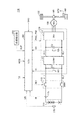
図1は、本発明の実施の形態1に従う車両100の全体ブロック図である。以下で詳細に説明されるように、車両100は、駆動源として回転電機を用いる電気自動車あるいは燃料電池車である。[Embodiment 1]
FIG. 1 is an overall block diagram of a
図1を参照して、車両100は、蓄電装置110と、システムメインリレー(System Main Relay:SMR)115と、駆動装置であるPCU(Power Control Unit)120と、モータジェネレータ130と、動力伝達ギヤ140と、駆動輪150と、斜度検出部200と、制御装置であるECU(Electronic Control Unit)300とを備える。PCU120は、コンバータ121と、インバータ122と、電圧センサ180,185と、コンデンサC1,C2とを含む。
Referring to FIG. 1,
蓄電装置110は、充放電可能に構成された電力貯蔵要素である。蓄電装置110は、たとえば、リチウムイオン電池、ニッケル水素電池または鉛蓄電池などの二次電池、あるいは電気二重層キャパシタなどの蓄電素子を含んで構成される。
The
蓄電装置110は、電力線PL1およびNL1を介してPCU120に接続される。そして、蓄電装置110は、車両100の駆動力を発生させるための電力をPCU120に供給する。また、蓄電装置110は、モータジェネレータ130で発電された電力を蓄電する。蓄電装置110の出力はたとえば200V程度である。
蓄電装置110には、電圧センサ170および電流センサ175が設けられる。電圧センサ170は、蓄電装置110の電圧VBを検出し、その検出結果をECU300へ出力する。電流センサ175は、蓄電装置に入出力される電流IBを検出し、その検出値をECU300へ出力する。
The
SMR115に含まれるリレーは、その一方端が蓄電装置110の正極端子および負極端子に接続され、他方端がPCU120に接続される電力線PL1,NL1に接続される。そして、SMR115は、ECU300からの制御信号SE1に基づいて、蓄電装置110とPCU120との間における電力の供給と遮断とを切換える。
The relay included in
コンバータ121は、ECU300からの制御信号PWCに基づいて、電力線PL1,NL1と電力線PL2,NL1との間で電圧変換を行なう。
インバータ122は、電力線PL2,NL1に接続される。インバータ122は、ECU300からの制御信号PWIに基づいて、コンバータ121から供給される直流電力を交流電力に変換し、モータジェネレータ130を駆動する。
コンデンサC1は、電力線PL1およびNL1の間に設けられ、電力線PL1およびNL1間の電圧変動を減少させる。また、コンデンサC2は、電力線PL2およびNL1の間に設けられ、電力線PL2およびNL1間の電圧変動を減少させる。 Capacitor C1 is provided between power lines PL1 and NL1, and reduces voltage fluctuation between power lines PL1 and NL1. Capacitor C2 is provided between power lines PL2 and NL1, and reduces voltage fluctuation between power lines PL2 and NL1.
電圧センサ180および185は、それぞれコンデンサC1およびC2の両端にかかる電圧VLおよびVHを検出し、その検出値をECU300へ出力する。
モータジェネレータ130は交流回転電機であり、たとえば、永久磁石が埋設されたロータを備える永久磁石型同期電動機である。
モータジェネレータ130の出力トルクは、減速機や動力分割機構を含んで構成される動力伝達ギヤ140を介して駆動輪150に伝達されて、車両100を走行させる。モータジェネレータ130は、車両100の回生制動動作時には、駆動輪150の回転によって発電することができる。そして、その発電電力は、PCU120によって蓄電装置110の充電電力に変換される。
The output torque of
車両100の速度(車速)を検出するために、速度センサ190が駆動輪150の近傍に設けられる。速度センサ190は、駆動輪150の回転速度に基づいて車速SPDを検出し、その検出値をECU300に出力する。また、速度センサとして、モータジェネレータ130の回転角を検出するための回転角センサ(図示せず)を用いてもよい。この場合には、ECU300は、モータジェネレータ130の回転角の時間的変化および減速比などに基づいて、間接的に車速SPDを演算する。
In order to detect the speed (vehicle speed) of the
斜度検出部200は、車両100が走行している路面の斜度を検出する。そして、斜度検出部200は、検出した斜度の検出値SLPをECU300へ出力する。斜度検出部200としては、たとえば、傾斜センサやGセンサなどを用いることができる。
The
ECU300は、いずれも図1には図示しないがCPU(Central Processing Unit)、記憶装置および入出力バッファを含み、各センサ等からの信号の入力や各機器への制御信号の出力を行なうとともに、蓄電装置110および車両100の各機器の制御を行なう。なお、これらの制御については、ソフトウェアによる処理に限られず、専用のハードウェア(電子回路)で処理することも可能である。
Although not shown in FIG. 1,
ECU300は、PCU120、SMR115などを制御するための制御信号を生成して出力する。なお、図1においては、ECU300として1つの制御装置を設ける構成としているが、たとえば、PCU120用の制御装置や蓄電装置110用の制御装置などのように、機能ごとまたは制御対象機器ごとに個別の制御装置を設ける構成としてもよい。
ECU300は、蓄電装置110に備えられる電圧センサ170,電流センサ175からの電圧VBおよび電流IBの検出値に基づいて、蓄電装置110の充電状態SOC(State of Charge)を演算する。
ECU300は、ユーザによるアクセルペダル(図示せず)の操作に基づいて定められる要求トルクTRを、上位ECU(図示せず)から受ける。ECU300は、ユーザからの要求トルクTRに基づいて、コンバータ121およびインバータ122の制御信号PWC,PWIをそれぞれ生成し、モータジェネレータ130を駆動する。
また、ECU300は、ユーザにより設定されるモード信号MODを受ける。このモード信号MODは、以下に後述する慣性走行制御を実行するか否かを指示するための信号である。モード信号MODは、特定のスイッチや操作画面における設定などによって切換えられる。あるいは、特定の条件が成立したことに応答して、モード信号MODが自動的に設定されるようにしてもよい。
ECU300は、たとえば、モード信号MODがオンに設定されている場合には、慣性走行制御を行なうように動作し、モード信号MODがオフに設定されている場合には、慣性走行制御を行なわない通常の走行を行なうように動作する。
このような車両においては、モータジェネレータ130から駆動力が発生されると、蓄電装置の電力が消費される。蓄電装置110の容量は予め定められているので、蓄電装置に蓄えられた電力で、できるだけ長距離を走行するためには、走行中のエネルギ効率を向上させて電力消費を抑制することが必要となる。
In such a vehicle, when driving force is generated from
車両の走行中には車両には慣性力がはたらいているため、走行中にモータジェネレータによる駆動力を、車速を維持するために必要な駆動力よりも低くした場合は、徐々に車速は低下するものの、しばらくの間は車両の慣性力を用いて走行(以下、「慣性走行」とも称する。)が継続される。 Since the inertial force is applied to the vehicle while the vehicle is running, if the driving force generated by the motor generator is made lower than the driving force required to maintain the vehicle speed while the vehicle is running, the vehicle speed gradually decreases. However, traveling for a while using the inertial force of the vehicle (hereinafter also referred to as “inertia traveling”) is continued.
この慣性走行中は、モータジェネレータにより出力される駆動力が小さいので、蓄電装置からの電力消費が少なくなる。そのため、慣性走行を活用して走行を行なうことができれば、車両走行時のエネルギ効率を改善することが可能となり得る。 During this inertia traveling, the driving force output by the motor generator is small, so that the power consumption from the power storage device is reduced. Therefore, if traveling can be performed using inertial traveling, it may be possible to improve energy efficiency during vehicle traveling.
そこで、実施の形態1においては、図1に示した車両において、ユーザからの要求トルクがほぼ一定であり、それによって車速がほぼ一定に維持されるような走行がされている場合に、モータジェネレータからの駆動力が高出力状態である加速走行を行なう場合と、モータジェネレータの駆動力が低出力状態(駆動力がゼロの場合も含む)である慣性走行を行なう場合とを繰り返して走行する運転(以下、「駆動力変更運転」とも称する。)を行なう慣性走行制御を実行し、走行中におけるエネルギ効率の向上を図る。 Therefore, in the first embodiment, when the vehicle shown in FIG. 1 is running such that the torque requested by the user is substantially constant and the vehicle speed is thereby maintained substantially constant, the motor generator Driving that repeats driving when acceleration driving with a high output power from the vehicle and inertial driving when the driving power of the motor generator is low (including when the driving power is zero) (Hereinafter, also referred to as “driving force changing operation”) is performed to improve the energy efficiency during traveling.
また、実施の形態1おいては、上記の慣性走行制御は、下り坂および登り坂のような斜度を有する路面を走行する際にも適用される。ところが、このような斜度を有する路面の場合には、慣性走行を行なっている際に、車両に作用する重力の影響のために、平坦路を走行している場合に比べて減速度が増減し得る。そうすると、駆動力変更運転中に斜度が変化した場合に、減速度の変化によって運転手にトルクショックを与えてしまうおそれがある。 In the first embodiment, the inertial traveling control described above is also applied when traveling on a road surface having an inclination such as a downhill and an uphill. However, in the case of a road surface having such an inclination, the deceleration increases or decreases compared to when traveling on a flat road due to the influence of gravity acting on the vehicle during inertial traveling. Can do. Then, when the inclination changes during the driving force changing operation, there is a possibility that a torque shock is given to the driver due to the change in the deceleration.
このような減速度の変動に対応するために、慣性走行中にモータジェネレータによって、重力の影響による減速度変動を相殺するようなトルクを発生させて、平坦路を走行する場合の減速度と、下り坂または登り坂を走行する場合の減速度をほぼ同じレベルとするように制御される場合がある。 In order to cope with such fluctuations in deceleration, the motor generator generates a torque that cancels the fluctuations in deceleration due to the influence of gravity during inertial running, and the deceleration when traveling on a flat road, In some cases, the deceleration when traveling downhill or uphill is controlled so as to be approximately the same level.
(下り坂の場合)
下り坂の場合には、重力により減速度が低減され、車速が減速しにくくなるため、慣性走行中に、モータジェネレータにより回生トルクを発生させることによって、重力により低減される減速度を補償する。(Downhill)
In the case of a downhill, the deceleration is reduced by gravity, and the vehicle speed is difficult to decelerate. Therefore, the deceleration reduced by gravity is compensated by generating regenerative torque by the motor generator during inertial running.
このとき、下り坂で回生制動を行なった場合には、モータジェネレータは回生制動により発電し、その発電電力が蓄電装置に蓄えられる。しかしながら、この場合に、蓄電装置におけるSOCが使用許可範囲の上限値に到達すると、それ以降は蓄電装置を充電することができないので、慣性走行時の回生動作ができなくなる。そのため、たとえば、長い下り坂を走行するような場合には、下り坂の途中で回生動作が停止されてしまい、慣性走行時の減速度が変化し、運転者のフィーリングに影響を与える可能性がある。 At this time, when regenerative braking is performed on a downhill, the motor generator generates power by regenerative braking, and the generated power is stored in the power storage device. However, in this case, when the SOC of the power storage device reaches the upper limit value of the use-permitted range, the power storage device cannot be charged thereafter, so that the regenerative operation during inertia traveling cannot be performed. Therefore, for example, when traveling on a long downhill, the regenerative operation is stopped in the middle of the downhill, and the deceleration during inertial traveling may change, which may affect the driver's feeling. There is.
そこで、実施の形態1においては、下り坂において慣性走行制御を実行する場合は、蓄電装置のSOCの使用許可範囲を定める上限値を一時的に緩和させて大きい値に変更する。これによって、できるだけ長い期間、慣性走行時の回生制動を継続させて、ドライバビリティを向上させる。 Therefore, in the first embodiment, when the inertial traveling control is executed on the downhill, the upper limit value that defines the use permission range of the SOC of the power storage device is temporarily relaxed and changed to a larger value. As a result, regenerative braking during inertial running is continued for as long as possible to improve drivability.
なお、SOCの使用許可範囲の上限値は、直ちに蓄電装置の故障につながる限界値に対して、一定のマージンが設けられるのが一般的である。さらに、下り坂の継続する期間は比較的短い。そのため、下り坂が継続する短い期間に上限値を緩和させても、直ちに蓄電装置の劣化や故障に至る可能性は非常に低い。 In general, the upper limit value of the allowable use range of the SOC is provided with a certain margin with respect to the limit value that immediately leads to the failure of the power storage device. Furthermore, the downhill duration is relatively short. Therefore, even if the upper limit value is relaxed in a short period during which the downhill continues, there is a very low possibility that the power storage device will immediately deteriorate or fail.
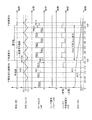
図2は、実施の形態1において、車両100が下り坂を走行する場合の、慣性走行制御を説明するための図である。図2においては、横軸には時間が示され、縦軸には、路面の斜度、車速SPD、モータジェネレータの出力、ユーザからの要求パワー、蓄電装置(バッテリ)の充放電電力、および蓄電装置のSOCが示される。なお、蓄電装置の充放電電力については、放電電力が正値で表わされ、充電電力が負値で表わされている。
FIG. 2 is a diagram for illustrating inertial traveling control when the
図1および図2を参照して、まず、車両100が、平坦な道路を一定の車速V1で走行している場合(〜時刻t6)を考える。この場合、図2のように、ユーザから要求されるパワーは、ほぼ一定の値として与えられる。なお、「ユーザから要求されるパワーがほぼ一定の値である」とは、多少の変動はあるものの、ある所定時間内において、ユーザ要求パワーが予め定められた所定範囲内(たとえば、±3%)に維持される状態を意味する。
Referring to FIGS. 1 and 2, first, consider a case where
実施の形態1の慣性走行制御を適用しない場合においては、モータジェネレータ130の出力は、図2中の破線W13のように、ほぼ一定の大きさで連続して出力される。これにより、車速SPDは、図2中の破線W11のように、ほぼ一定に維持される。
In the case where the inertial traveling control of the first embodiment is not applied, the output of
このとき、蓄電装置110からは、図2中の破線W15のように一定の電力が連続して出力されるために、蓄電装置110のSOCは、図2中の破線W18のように、直線的に減少する。
At this time, since constant power is continuously output from
そして、時刻t6において路面の斜度が変化し、車両100が下り坂にさしかかると、車両100に作用する重力の影響によって車両進行方向に作用する駆動力が実質的に増加され、減速度が低下し逆に加速度が増加してしまう。これによって、車速が上昇してしまい、車速を許容範囲内に維持することができなくなる場合がある。そうすると、先行車との車間距離が徐々に短くなり、衝突などの原因になる可能性がある。
When the slope of the road surface changes at time t6 and the
一方、実施の形態1の慣性走行制御を適用した場合には、基本的には、モータジェネレータ130を所定の駆動力で走行する加速走行と、加速走行時の駆動力よりも小さい駆動力で走行する慣性走行とが交互に繰り返される。なお、慣性走行時においては、モータジェネレータ130からの駆動力がゼロ、すなわちモータジェネレータ130が停止状態の場合も含まれる。図2においては、平坦路の場合の慣性走行時にはモータジェネレータ130を停止状態とする場合を例として説明する。
On the other hand, when the inertial traveling control according to the first embodiment is applied, basically, the
具体的には、時刻t1までは、実施の形態1の慣性走行制御が適用されていない状態であり、モータ出力PM0が連続的に出力されている。 Specifically, until time t1, the inertial traveling control according to the first embodiment is not applied, and the motor output PM0 is continuously output.
時刻t1において、ユーザにより慣性走行制御の実行が指示されると、まずモータジェネレータ130が停止される(図2中の実線W12)。そうすると、モータジェネレータ130からの駆動力がなくなるので、図2中の実線W10のように、慣性力による走行が開始されて徐々に車速SPDが低下する。
When execution of inertial running control is instructed by the user at time t1,
このとき、蓄電装置110からの充放電電力がゼロとなるので、SOCの低下が抑制される。
At this time, the charge / discharge power from
そして、車速SPDが、目標とする車速V1に対して予め定められた許容範囲の下限値LLまで低下すると(図2中の時刻t2)、モータジェネレータ130の駆動が再開される。このときのモータ出力は、車速V1を維持するために必要とされる出力PM0よりも大きいPM1に設定される。これによって、車両100が加速する。このとき、駆動力発生中は、慣性走行を行なわない場合に比べるとSOCの減少量は大きくなるが、時刻t1からt2までの慣性走行により電力が消費されていないため、トータルのSOCは高い状態が維持される(図2中の実線W16)。
Then, when vehicle speed SPD falls to lower limit value LL within a predetermined allowable range for target vehicle speed V1 (time t2 in FIG. 2), driving of
そして、車速SPDが予め定められた上記の許容範囲の上限値ULまで上昇すると、再びモータジェネレータ130が停止され(図2中の時刻t3)、慣性走行が実行される。
Then, when vehicle speed SPD rises to a predetermined upper limit value UL of the allowable range,
その後、同様に、車速SPDが下限値LLまで低下するとモータジェネレータ130が駆動され、さらに車速SPDが上限値ULまで上昇するとモータジェネレータ130が停止される。
Thereafter, similarly, when vehicle speed SPD decreases to lower limit value LL,
このような駆動力変更運転を繰り返すことによって、車速SPDは上記の許容範囲内では変動するものの、平均速度をほぼV1に維持しながら、蓄電装置のSOCの減少を抑制することができる。その結果、全体としてエネルギ効率が向上され、蓄電装置に蓄えられた電力による走行可能距離を拡大することができる。 By repeating such driving force changing operation, although the vehicle speed SPD varies within the allowable range, it is possible to suppress the decrease in the SOC of the power storage device while maintaining the average speed substantially at V1. As a result, energy efficiency is improved as a whole, and the travelable distance by the electric power stored in the power storage device can be increased.
そして、時刻t6において路面の斜度が変化し、車両100が下り坂にさしかかると、斜度変化に対応して、加速走行時のモータジェネレータ130の駆動力がPM2(<PM1)に低減される。このように、モータジェネレータ130の駆動力を低下することによって、車両に作用する重力に相当する駆動力が低減できるので、結果として車速の上昇を抑制することが可能となる。
Then, when the slope of the road surface changes at time t6 and the
また、下り坂を走行している間の慣性走行時には、モータジェネレータ130は負のトルク(回生トルク)が発生するような出力PMRとなるように制御される。これによって、重力の作用による加速度を相殺して、平坦路を走行する場合の慣性走行中の減速度を維持することができる。
Further, during inertia traveling while traveling downhill, the
モータジェネレータ130が回生動作を行なっている間は、モータジェネレータ130によって発電が行なわれる。そして、慣性走行時の回生動作による制動力PMRが加速走行時の駆動力PM2より大きい場合には、図2の実線W16のように、下り坂を走行している間に、徐々にSOCが増加する。
While the
さらに、下り坂を走行している間には、SOCの使用許可範囲を定める上限値SHLが、平坦路走行の場合のS1よりも大きいS2(S1<S2)に拡大される(図2の実線W17)。これによって、慣性走行制御を実行しながら下り坂を走行している間に、SOCが拡大された上限値S2に到達するまでは、慣性走行中の回生動作が許可される(図2中の時刻t12〜t13)。 Further, while traveling downhill, the upper limit value SHL that defines the SOC use permission range is expanded to S2 (S1 <S2) that is larger than S1 in the case of traveling on a flat road (solid line in FIG. 2). W17). As a result, the regenerative operation during inertial traveling is permitted until the SOC reaches the enlarged upper limit value S2 while traveling downhill while performing inertial traveling control (time in FIG. 2). t12-t13).
そして、時刻t14において平坦路に復帰すると、SOCの上限値が通常のS1に戻される。 When the vehicle returns to a flat road at time t14, the upper limit value of the SOC is returned to normal S1.
なお、下り坂を走行する際のモータ出力の設定については、たとえば、重力による影響を相殺して平坦路を走行しているときの加速度と同等の加速度が得られるように設定してもよいし、加速走行の時間と慣性走行の時間との和が平坦路と下り坂とで同等となるように設定してもよい。さらに、モータ出力は、斜度の大きさに応じて変化するようにすることが望ましく、下り坂の斜度がさらに増加したような場合には、それに対応してモータ出力をさらに低下するようにしてもよい。 The setting of the motor output when traveling on the downhill may be set such that, for example, the acceleration equivalent to the acceleration when traveling on a flat road can be obtained by offsetting the influence of gravity. The sum of the acceleration traveling time and the inertia traveling time may be set to be equal between the flat road and the downhill. Furthermore, it is desirable that the motor output changes according to the magnitude of the inclination, and when the downhill inclination further increases, the motor output is further reduced accordingly. May be.
また、図2においては、斜度の変化がステップ状に変化する場合を例として説明したが、斜度が連続的に増加するような場合には、それに対応して、モータ出力も連続的に増加させるようにしてもよい。 In FIG. 2, the case where the change in the gradient changes stepwise has been described as an example. However, in the case where the gradient increases continuously, the motor output also correspondingly increases. You may make it increase.
実施の形態1の慣性走行制御においては、上述のように、ユーザからの要求パワーがほぼ一定である場合に、図2で示したような駆動力変更運転が実行される。一方で、ユーザからの要求パワーが変動する加速時および減速時には、駆動力変更運転は実行されない。ユーザ要求パワーが増加する加速時においては、モータジェネレータ130から連続的に駆動力が出力されて車両を加速する。また、ユーザ要求パワーが減少する減速時においては、モータジェネレータ130からの駆動力が停止または低下されて、所望の車速まで減速される。
In the inertial running control of the first embodiment, as described above, the driving force changing operation as shown in FIG. 2 is executed when the power required by the user is substantially constant. On the other hand, the driving force changing operation is not executed at the time of acceleration and deceleration when the required power from the user fluctuates. At the time of acceleration when the user requested power increases, the driving force is continuously output from the
図3は、実施の形態1において、下り坂を走行する場合に、ECU300で実行される慣性走行制御処理を説明するためのフローチャートである。図3および後述する図5,8に示されるフローチャート中の各ステップについては、ECU300に予め格納されたプログラムを所定周期で実行することによって実現される。あるいは、一部のステップについては、専用のハードウェア(電子回路)を構築して処理を実現することも可能である。
FIG. 3 is a flowchart for illustrating an inertia traveling control process executed by
図1および図3を参照して、ECU300は、ステップ(以下、ステップをSと略す。)100にて、ユーザによって設定されるモード信号MODに基づいて、慣性走行制御が選択されているか否かを判定する。
Referring to FIGS. 1 and 3,
モード信号MODがオフに設定されており、慣性走行制御が選択されていない場合(S100にてNO)は、以降の処理がスキップされ、ECU300は処理をメインルーチンに戻す。
If mode signal MOD is set to OFF and inertial running control is not selected (NO in S100), the subsequent processing is skipped, and
モード信号MODがオンに設定されており、慣性走行制御が選択されている場合(S100にてYES)は、処理がS110に進められ、ECU300は、次に、要求トルクTRに基づいて、ユーザからの要求パワーがほぼ一定であるか否かを判定する。
If mode signal MOD is set to ON and inertial running control is selected (YES in S100), the process proceeds to S110, and
ユーザ要求パワーがほぼ一定である場合(S110にてYES)は、処理がS120に進められて、ECU300は、駆動力変更運転を実行するように選択する。なお、図3には示されていないが、駆動力変更運転の開始直後は、図2に示されるように、まず、モータジェネレータ130が停止されて慣性走行が実行される。
If the user requested power is substantially constant (YES in S110), the process proceeds to S120, and
ECU300は、次に、S130にて、斜度検出部200からの信号SLPに基づいて、下り坂が検出されたか否かを判定する。
Next, in S130,
下り坂が検出されない場合(S130にてNO)は、S140に処理が進められ、ECU300は、加速走行時のモータ駆動力として平坦路を走行する際の駆動力を設定するとともに、蓄電装置110のSOCの上限値SHLをS1に設定する。その後、処理がS150に進められる。
When the downhill is not detected (NO in S130), the process proceeds to S140, and
一方、下り坂が検出された場合(S130にてYES)は、処理がS145に進められ、ECU300は、斜度に応じて平坦路の場合よりも低減された駆動力を、加速走行時のモータ駆動力として設定するとともに、SOCの上限値SHLをS2(>S1)に設定する。そして、ECU300は処理をS150へ進める。
On the other hand, if a downhill is detected (YES in S130), the process proceeds to S145, and
その後、ECU300は、S150にて、車速SPDが速度許容範囲の上限値ULまで上昇したか否かを判定する。
Thereafter,
上記のように、駆動力変更運転の開始直後は、まずモータジェネレータ130が停止されて慣性走行が実行されるので、車速SPDは上限値ULよりも低く、かつ徐々に車速SPDは低下する。
As described above, immediately after the start of the driving force change operation, first, the
すなわち、車速SPDが速度許容範囲の上限値ULまで上昇していないので(S150にてNO)、処理がS155に進められて、次に、ECU300は、車速SPDが速度許容範囲の下限値LLまで低下したか否かを判定する。
That is, since vehicle speed SPD has not risen to upper limit value UL of the allowable speed range (NO in S150), the process proceeds to S155, and then
車速SPDが速度許容範囲内で低下中(LL<SPD<UL)の場合、すなわち、車速SPDが速度許容範囲の下限値LLまで低下していない場合(S155にてNO)は、処理がS174に進められ、ECU300は、現在のモータジェネレータ130の状態を保持し、慣性走行を継続する。その後、メインルーチンに処理が戻され、次回の制御周期において再びS100から処理が実行される。
If vehicle speed SPD is decreasing within the allowable speed range (LL <SPD <UL), that is, if vehicle speed SPD has not decreased to lower limit value LL of the allowable speed range (NO in S155), the process proceeds to S174. The
慣性走行が継続されている間に、車速SPDが速度許容範囲の下限値LLまで低下した場合(SPD≦LL)(S155にてYES)は、処理がS172に進められ、ECU300は、S140またはS145で設定された駆動力を用いてモータジェネレータ130を駆動して加速走行を実行する。これにより、車速SPDが上昇する。
If vehicle speed SPD decreases to lower limit value LL of the allowable speed range while inertial traveling is continued (SPD ≦ LL) (YES in S155), the process proceeds to S172, and
この加速走行が実行されて速度許容範囲内で車速が上昇している間は、S150およびS155でNOが選択されて、ECU300は、S174にて、車速SPDが速度許容範囲の上限値ULに到達するまで加速走行を継続する。
While this acceleration traveling is executed and the vehicle speed is rising within the allowable speed range, NO is selected in S150 and S155, and in S174, the
なお、加速走行が実行されている間に、下り坂から平坦路へ復帰した場合には、S130およびS140によって、モータ駆動力が平坦路の場合の駆動力に戻される。 If the vehicle returns from the downhill to the flat road while the acceleration travel is being executed, the motor driving force is returned to the driving force in the case of the flat road through S130 and S140.
そして、車速SPDが速度許容範囲の上限値ULまで上昇すると(S150にてYES)、ECU300は加速走行から慣性走行に切換え、処理をS160に進めて、現在車両100が下り坂を走行中であり、かつ蓄電装置110のSOCがS145で設定された上限値S2より小さいか否かを判定する。
When vehicle speed SPD increases to upper limit value UL of the allowable speed range (YES in S150),
車両100が下り坂を走行中であり、かつ蓄電装置110のSOCがS145で設定された上限値S2より小さい場合(S160にてYES)には、処理がS171に進められて、ECU300は、モータジェネレータ130の回生運転を行なって、平坦路走行時の減速度が維持されるようにしつつ、慣性走行を実行する。
If
一方、車両100が下り坂を走行中でない場合、あるいは、下り坂を走行中であってもSOCが上限値S2以上となった場合(S160にてNO)には、処理がS170に進められて、ECU300はモータジェネレータ130を停止した慣性走行を実行する。
On the other hand, if
ユーザ要求パワーがほぼ一定に保持されている間は、車速SPDが速度許容範囲内に維持されるように、上記のような駆動力変更運転が実行される。 While the user request power is held substantially constant, the driving force changing operation as described above is executed so that the vehicle speed SPD is maintained within the speed allowable range.
一方、加速または減速のために、ユーザからの要求パワーが変動した場合(S110にてNO)は、処理がS125に進められて、ECU300は、駆動力変更運転を中断する。
On the other hand, when the power required by the user fluctuates due to acceleration or deceleration (NO in S110), the process proceeds to S125, and
そして、ECU300は、ユーザ要求パワーによって加速が指示されている場合(S127にてYES)は、モータジェネレータ130を力行状態で駆動して、車両100を加速する(S176)。
一方、ユーザから減速が指示されている場合(S127にてNO)は、処理がS148に進められ、ECU300は、モータジェネレータ130を停止した慣性走行による減速を実行する(S178)。または、より迅速に減速することが必要な場合には、モータジェネレータ130を回生状態で駆動することによる回生制動を伴う減速を実行する。あるいは、慣性走行による減速と回生制動を伴う減速とを切換えながら減速するようにしてもよい。
On the other hand, when deceleration is instructed by the user (NO in S127), the process proceeds to S148, and
その後、ユーザによる加速または減速動作が終了して、ユーザ要求パワーがほぼ一定である状態になると(S110にてYES)、駆動力変更運転が再開される。 Thereafter, when the acceleration or deceleration operation by the user is finished and the user required power is almost constant (YES in S110), the driving force changing operation is resumed.
以上のような処理に従って制御を行なうことによって、ユーザからの要求パワーがほぼ一定である状態において、慣性走行と加速走行とが繰り返される駆動力変更運転が実行できる。そして、路面の斜度が変化して下り坂を走行する場合には、下り方向の斜度の増加に応じてモータジェネレータの駆動力が低減される。さらに、下り坂走行時に、蓄電装置のSOCの上限値を緩和することによって、慣性走行時にモータジェネレータによる回生動作をより長く継続することができるので、できるだけ長い間、平坦路走行時と同じレベルの減速度を維持することが可能となる。これによって、下り坂において重力の影響によって車速が上昇することを抑制しつつ、車両走行時のエネルギ効率を向上させることができるとともに、下り坂走行時のドライバビリティを向上させることができる。 By performing control according to the above-described process, it is possible to execute a driving force change operation in which inertial traveling and acceleration traveling are repeated in a state where the power required by the user is substantially constant. When the slope of the road surface changes and the vehicle travels on a downhill, the driving force of the motor generator is reduced as the slope in the downward direction increases. Furthermore, by relieving the upper limit value of the SOC of the power storage device when traveling downhill, the regenerative operation by the motor generator can be continued for a longer time during inertial travel, so that the same level as when traveling on a flat road for as long as possible. The deceleration can be maintained. As a result, it is possible to improve the energy efficiency during traveling of the vehicle and to improve drivability during traveling downhill while suppressing an increase in vehicle speed due to the influence of gravity on the downhill.
(登り坂の場合)
登り坂の場合には、重力により増加される減速度を補償するために、慣性走行中に増加される減速度に対応する駆動力がモータジェネレータから発生される。(In the case of uphill)
In the case of an uphill, in order to compensate for the deceleration increased by gravity, a driving force corresponding to the deceleration increased during inertial running is generated from the motor generator.
このとき、登り坂の慣性走行時に駆動力を発生すると、さらなる電力が蓄電装置から出力される。しかしながら、この場合に、蓄電装置におけるSOCの使用許可範囲の下限値値に到達すると、それ以降は蓄電装置から電力を出力することができなくなるため、慣性走行制御が継続できなくなってしまう。 At this time, if driving force is generated during inertia traveling on an uphill, further electric power is output from the power storage device. However, in this case, if the lower limit value of the SOC use permission range in the power storage device is reached, power cannot be output from the power storage device thereafter, and inertial traveling control cannot be continued.
そこで、実施の形態1においては、登り坂において慣性走行制御を実行する場合は、蓄電装置のSOCの使用許可範囲を定める下限値を一時的に緩和させてより小さい値に変更する。これによって、少なくとも登り坂を登りきるまで慣性走行制御を継続させ、登り坂を走行中の速度が低下されることに起因して生じ得る交通渋滞や追突事故を防止する。 Therefore, in the first embodiment, when the inertial traveling control is executed on the uphill, the lower limit value that defines the allowable use range of the SOC of the power storage device is temporarily relaxed and changed to a smaller value. In this way, the inertial traveling control is continued at least until the vehicle climbs up the hill, thereby preventing traffic jams and rear-end collisions that may occur due to a decrease in speed while traveling up the hill.
なお、SOCが下限値を下回ると、一般的には蓄電装置からの電力の出力が禁止されるが、下り坂の場合と同様に、通常、蓄電装置内の電力が完全に枯渇する状態までには多少のマージンが設けられる。そのため、たとえば、緊急時対応として、スイッチ等を用いてより低いSOCまで蓄電装置の電力を使用できるようにすることで、たとえSOCが下限値を下回った場合でも、短時間であれば蓄電装置に残存する電力を用いることができるようにしてもよい。これにより、少なくとも直近の充電ステーションまでは走行可能とすることができる。 Note that when the SOC falls below the lower limit, the output of power from the power storage device is generally prohibited, but normally, until the power in the power storage device is completely depleted, as in the downhill case. Some margin is provided. Therefore, for example, as an emergency response, by using a switch or the like so that the power of the power storage device can be used up to a lower SOC, even if the SOC falls below the lower limit value, The remaining electric power may be used. Thereby, it can be made possible to travel at least to the nearest charging station.
図4は、実施の形態1において、車両100が登り坂を走行する場合の、慣性走行制御を説明するための図である。
FIG. 4 is a diagram for illustrating the inertia traveling control when the
図1および図4を参照して、時刻t26までは、図2で示した下り坂の場合と同様に、車両100は、モータジェネレータ130の駆動と停止とを繰り返しながら走行する慣性走行制御を実行しながら、平坦路を走行している。
Referring to FIGS. 1 and 4, until time t <b> 26, as in the case of the downhill shown in FIG. 2,
そして、時刻t26において平坦路から登り坂にさしかかると、加速走行における駆動力を、車両に作用する重力の影響により増加する減速度を補償するために、平坦路の駆動力PM1AからPM2Aに増加される。 When the vehicle starts to climb up from the flat road at time t26, the driving force in the acceleration traveling is increased from the driving force PM1A on the flat road to PM2A in order to compensate for the deceleration that increases due to the influence of gravity acting on the vehicle. The
また、慣性走行においても、車両に作用する重力の影響により増加する減速度を補償するための低出力の駆動力PMLがモータジェネレータ130から出力される。これによって、登り坂走行における慣性走行時の減速度を平坦路走行における慣性走行時の減速度とを同じレベルに維持することができる。
Also in the inertial running, the
さらに、登り坂を走行中の図4の時刻t26〜t34までは、SOCの使用許可範囲を定める下限値SLLが、平坦路走行時の下限値S3よりも低いS4(<S3)に設定される(図4中の実線W23)。 Further, from time t26 to time t34 in FIG. 4 during traveling on the uphill, the lower limit value SLL that defines the allowable use range of the SOC is set to S4 (<S3), which is lower than the lower limit value S3 when traveling on a flat road. (Solid line W23 in FIG. 4).
これによって、図4中の時刻t32付近から時刻t34までのように、SOCが通常の下限値S3を下回った場合でも、登り坂を登りきるまでは、蓄電装置110からの電力を用いて慣性走行制御を継続することができる。
As a result, even when the SOC falls below the normal lower limit value S3, from around time t32 in FIG. 4 to time t34, the inertial running is performed using the electric power from the
図5は、登り坂を走行する場合に、ECU300で実行される慣性走行制御処理を説明するためのフローチャートである。図5は、下り坂の場合に図3で示したフローチャートにおけるステップS130,S140,S145,S160,S171,S172が、それぞれS130A,S140A,S145A,S160A,S171A,S172Aに置き換わったものとなっている。図5において、図3と重複するステップの説明は繰り返さない。
FIG. 5 is a flowchart for illustrating an inertia traveling control process executed by
図1および図5を参照して、慣性走行制御が選択され(S100にてYES)、かつユーザ要求パワーがほぼ一定であると判定されて(S110にてYES)、駆動力変更運転の実行が開始されると(S120)、処理がS130Aに進められて、ECU300は、斜度検出部200からの信号SLPに基づいて、車両100が現在登り坂を走行中であるか否かを判定する。
Referring to FIGS. 1 and 5, inertial running control is selected (YES in S100), and it is determined that the user required power is substantially constant (YES in S110), and the driving force changing operation is executed. When started (S120), the process proceeds to S130A, and
登り坂が検出されない場合(S130AにてNO)は、S140Aに処理が進められ、ECU300は、加速走行時のモータ駆動力として平坦路を走行する際の駆動力を設定するとともに、蓄電装置110のSOCの下限値SLLをS3に設定する。
When an uphill is not detected (NO in S130A), the process proceeds to S140A, and
一方、登り坂が検出された場合(S130AにてYES)は、処理がS145Aに進められ、ECU300は、斜度に応じて平坦路の場合よりも増加された駆動力を、加速走行時のモータ駆動力として設定するとともに、SOCの下限値SLLをS4(<S3)に設定する。
On the other hand, when an uphill is detected (YES in S130A), the process proceeds to S145A, and
ECU300は、慣性走行において車速SPDが下限値LLまで低下すると(S155にてYES)、S140AまたはS145Aで設定された高出力の駆動力を用いてモータジェネレータ130を駆動し、加速走行を実行する(S172A)。
When the vehicle speed SPD decreases to the lower limit value LL in inertial traveling (YES in S155),
そして、加速走行実行中に、車速SPDが上限値ULまで上昇した場合(S150にてYES)は、ECU300は、処理をS160Aに進めて、車両100が現在登り坂を走行中であり、かつ蓄電装置110のSOCが下限値SLLよりも大きいか否かを判定する。
If the vehicle speed SPD increases to the upper limit value UL during execution of acceleration travel (YES in S150),
登り坂走行中ではなく、またはSOCが下限値SLL以下の場合(S160AにてNO)は、ECU300は、モータジェネレータ130を停止して慣性走行を実行する(S170)。
When the vehicle is not traveling uphill or the SOC is equal to or lower than lower limit value SLL (NO in S160A),
一方、登り坂走行中、かつSOCが下限値SLLより大きい場合(S160AにてYES)は、ECU300は、重力の影響による減速度の増加を補償する程度の低駆動力で、モータジェネレータ130を運転しながら慣性走行を実行する(S171A)。
On the other hand, when the vehicle is traveling uphill and the SOC is greater than lower limit value SLL (YES in S160A),
ユーザ要求パワーが変動し(S110にてNO)駆動力変更運転が中断される場合(S125)には、ECU300は、加速中であれば(S127にてYES)、モータジェネレータ130を駆動して加速する(S176)。また、減速中であれば(S127にてNO)、ECU300は、モータジェネレータ130を停止した慣性走行による減速または、より迅速に減速することが必要な場合には、モータジェネレータ130を回生状態で駆動することによる回生制動を伴う減速を実行する(S178)。あるいは、慣性走行による減速と回生制動を伴う減速とを切換えながら減速するようにしてもよい。
When the user requested power fluctuates (NO in S110) and the driving force change operation is interrupted (S125),
以上のような処理に従って制御を行なうことによって、ユーザからの要求パワーがほぼ一定である状態において、慣性走行と加速走行とが繰り返される駆動力変更運転が実行できる。そして、路面の斜度が変化して登り坂を走行する場合には、登り方向の斜度の増加に応じてモータジェネレータの駆動力が増加される。さらに、登り坂走行時に、蓄電装置のSOCの下限値を緩和することによって、少なくとも登り坂を登りきるまでは慣性走行を継続することができる。これによって、登り坂において重力の影響によって車速が低下することを抑制しつつ、車両走行時のエネルギ効率を向上させることができる。 By performing control according to the above-described process, it is possible to execute a driving force change operation in which inertial traveling and acceleration traveling are repeated in a state where the power required by the user is substantially constant. When the slope of the road surface changes and the vehicle travels on an uphill, the driving force of the motor generator is increased in accordance with the increase of the slope in the climb direction. Further, by relaxing the lower limit value of the SOC of the power storage device during the uphill running, the inertial running can be continued at least until the uphill is completely climbed. As a result, energy efficiency during vehicle travel can be improved while suppressing a decrease in the vehicle speed due to the influence of gravity on the uphill.
[実施の形態2]
実施の形態1では、駆動源としてモータジェネレータが単独で設けられる場合における慣性走行制御について説明した。[Embodiment 2]
In the first embodiment, the inertial running control in the case where a motor generator is provided alone as a drive source has been described.
実施の形態2においては、モータジェネレータに加えてエンジンを搭載したハイブリッド車両について慣性走行制御を適用する場合について説明する。 In the second embodiment, a case where inertia traveling control is applied to a hybrid vehicle equipped with an engine in addition to a motor generator will be described.
図6は、実施の形態2に従うハイブリッド車両100Aの全体ブロック図である。図6においては、図1におけるPCU120がPCU120Aに置き換えられ、駆動源として、モータジェネレータ130に代えて、モータジェネレータ130A,130Bおよびエンジン160が備えられる構成となっている。図6において、図1と重複する要素の説明は繰り返さない。
FIG. 6 is an overall block diagram of
図6を参照して、PCU120Aは、コンバータ121と、インバータ122A,122Bと、コンデンサC1,C2と、電圧センサ180,185とを含む。
Referring to FIG. 6,
インバータ122A,122Bは、電力線PL2,NL1を介して、コンバータ121に並列に接続される。
インバータ122Aは、ECU300からの制御信号PWI1により制御され、コンバータ121からの直流電力を交流電力に変換して、モータジェネレータ130A(以下、「MG1」とも称する。)を駆動する。また、インバータ122Aは、モータジェネレータ130Aで発電された交流電力を直流電力に変換し、コンバータ121を介して蓄電装置110を充電する。
インバータ122Bは、ECU300からの制御信号PWI2により制御され、コンバータ121からの直流電力を交流電力に変換して、モータジェネレータ130B(以下、「MG2」とも称する。)を駆動する。また、インバータ122Bは、モータジェネレータ130Bで発電された交流電力を直流電力に変換し、コンバータ121を介して蓄電装置110を充電する。
モータジェネレータ130A,130Bの各出力軸は、たとえばプラネタリギヤのような動力分割機構を含んで構成される動力伝達ギヤ140Aに結合される。そして、モータジェネレータ130A,130Bからの駆動力が駆動輪150に伝達される。
Each output shaft of
また、モータジェネレータ130A,130Bは、動力伝達ギヤ140Aを介して、エンジン160とも結合される。エンジン160は、ECU300からの制御信号DRVによって制御される。エンジン160から発生される駆動力は、動力伝達ギヤ140Aを介して駆動輪150およびモータジェネレータ130Aに伝達される。ECU300は、モータジェネレータ130A,130Bおよびエンジン160で発生される駆動力を協調的に制御して、車両を走行させる。
なお、実施の形態2においては、モータジェネレータ130Aは、エンジン160を始動する際のスタータモータとして用いられるとともに、エンジン160により駆動されて発電を行なう発電機として専ら用いられるものとする。また、モータジェネレータ130Bは、蓄電装置110からの電力を用いて駆動輪150を駆動するための電動機として専ら用いられるものとする。
In the second embodiment,
また、図6においては、2台のモータジェネレータと1台のエンジンが備えられる構成の例が示されるが、モータジェネレータの数はこれに限定されず、たとえば、モータジェネレータが1台であってもよい。あるいは、2台より多くのモータジェネレータが備えられる場合であってもよい。 FIG. 6 shows an example of a configuration in which two motor generators and one engine are provided. However, the number of motor generators is not limited to this. For example, even if there is only one motor generator, Good. Or the case where more than two motor generators are provided may be sufficient.
次に、図7および図8を用いて、実施の形態2における慣性走行制御を説明する。図7は、実施の形態2における慣性走行制御の概要を説明するためのタイムチャートであり、横軸には時間が示され、縦軸には、路面の斜度、車速SPD、モータジェネレータ(MG2)の出力、エンジンの出力、ユーザからの要求パワー、および蓄電装置の充放電電力が示される。なお、図7および図8においては、車両が下り坂を走行する場合を例として説明するが、車両が登り坂を走行する場合についても実施の形態1と同様に適用可能である。 Next, the inertial traveling control in the second embodiment will be described with reference to FIGS. FIG. 7 is a time chart for explaining an overview of the inertial traveling control in the second embodiment, where the horizontal axis indicates time, and the vertical axis indicates road slope, vehicle speed SPD, motor generator (MG2). ) Output, engine output, required power from the user, and charge / discharge power of the power storage device. 7 and 8, the case where the vehicle travels on a downhill will be described as an example, but the case where the vehicle travels on an uphill is also applicable as in the first embodiment.
図7を参照して、実施の形態2においては、慣性走行制御における加速走行時の駆動力を、モータジェネレータ130Bからの駆動力およびエンジン160からの駆動力によって生成する。具体的には、図7において平坦路を走行している時刻t41〜t46においては、モータジェネレータ130Bからの駆動力PM1Cとエンジン160からの駆動力PE1Cとの和が、車速を維持するために必要な駆動力PM0Cよりも大きくなるように設定される。また、下り坂を走行している時刻t46以降においては、モータジェネレータ130Bからの駆動力PM2Cとエンジン160からの駆動力PE2Cとの和が、平坦路走行時のトータル駆動力よりも小さくなるように設定される。
Referring to FIG. 7, in the second embodiment, the driving force during acceleration traveling in the inertial traveling control is generated by the driving force from
なお、加速走行時における、モータジェネレータ130Bからの駆動力とエンジン160からの駆動力の比率については、モータジェネレータ130Bおよびエンジン160のエネルギ効率を考慮して、トータルのエネルギ効率が高くなるように適宜設定される。
Note that the ratio of the driving force from
また、図7においては、加速走行のたびにエンジン160が始動されるので、加速走行が実行される直前において、モータジェネレータ130A(MG1)によってエンジン160がクランキングされる。
In FIG. 7,
図8は、実施の形態2において、ECU300で実行される慣性走行制御処理を説明するためのフローチャートである。図8は、実施の形態1の図3で説明したフローチャートにおけるステップS140,S145,S170,S172,S174,S176,S178が、それぞれS140B,S145B,S170B,S172B,S174B,S176B,S178Bに置き換えられたものとなっている。図8において、図3と重複するステップの説明は繰り返さない。
FIG. 8 is a flowchart for illustrating an inertial traveling control process executed by
図6および図8を参照して、図8におけるS140B,S145B,S170B,S172B,S174B,S176B,S178Bは、図3におけるS140,S145,S170,S172,S174,S176,S178において、モータジェネレータ130B(MG2)に加えてエンジン160についての駆動条件が追加されたものである。
Referring to FIGS. 6 and 8, S140B, S145B, S170B, S172B, S174B, S176B, and S178B in FIG. 8 are the same as
ユーザ要求パワーが一定であり(S110にてYES)駆動力変更運転が実行される場合(S120)には、ECU300は、路面が下り坂であるか否かに応じて、加速走行時のモータジェネレータ130Bおよびエンジン160の駆動力を設定するとともに、SOCの上限値SHLを設定する。具体的には、ECU300は、下り坂ではない場合(S130にてNO)は平坦路を走行する場合の駆動力を選択するとともに、SOCの上限値SHLをS1に設定する(S140B)。また、下り坂である場合(S130にてYES)は重力の影響を考慮して平坦路のときよりも小さな駆動力となるようにモータジェネレータ130Bおよびエンジン160の駆動力を設定する(S145B)。
When the user request power is constant (YES in S110) and the driving force change operation is executed (S120),
ECU300は、車速SPDが下限値LLまで低下すると(S155にてYES)、S140BまたはS145Bで設定された駆動力を用いてMG2およびエンジン160を駆動し、加速走行を実行する(S172B)。
When vehicle speed SPD decreases to lower limit value LL (YES in S155),
そして、ECU300は、車速SPDが上限値ULまで上昇し(S150にてYES)、下り坂走行中ではなく、またはSOCが上限値SHL以上場合(S160にてNO)は、MG2およびエンジン160を停止して慣性走行を実行する(S170B)。
一方、下り坂走行中、かつSOCが上限値SHLより小さい場合(S160にてYES)は、エンジン160が停止されるとともに、モータジェネレータ130Bを回生運転する(S171B)。
On the other hand, when the vehicle is traveling downhill and the SOC is smaller than upper limit value SHL (YES in S160),
また、ユーザ要求パワーが変動し(S110にてNO)駆動力変更運転が中断される場合(S125)には、ECU300は、加速中であれば(S127にてYES)、MG2あるいは、MG2およびエンジン160を併用して加速する(S176B)。また、減速中であれば(S127にてNO)、ECU300は、エンジン160を停止するとともに、MG2を停止または低出力状態に切換えて減速する(S178B)。なお、減速の際には、MG2の回生動作を実行して減速するようにしてもよい。
Further, when the user requested power fluctuates (NO in S110) and the driving force change operation is interrupted (S125),
以上ような処理に従って制御を行なうことによって、エンジンおよびモータジェネレータを駆動源とするハイブリッド車両において、下り坂を考慮した慣性走行制御を行なうことによってエネルギ効率の向上およびドライバビリティの向上を行なうことができる。 By performing control according to the above-described processing, in a hybrid vehicle using an engine and a motor generator as a drive source, it is possible to improve energy efficiency and driveability by performing inertial traveling control in consideration of downhill. .
なお、上記の説明においては、下り坂を走行する場合には、加速走行におけるMG2およびエンジン160の双方の駆動力を、平坦路に比べて小さくする場合を例として説明したが、MG2およびエンジン160のエネルギ効率および駆動力の応答性等を考慮して、MG2およびエンジン160のいずれか一方の駆動力を小さくするようにしてもよい。そして、特定の場合または特定のタイミングにおいては、MG2およびエンジン160のいずれか一方によって、トータル駆動力が出力されるようにしてもよい。
In the above description, when traveling downhill, the driving force of both MG2 and
また、図7および図8には示されないが、MG2については平坦路における慣性走行時、エンジン160については、平坦路および/または下り坂における慣性走行時において低駆動力で運転するようにしてもよい。
Although not shown in FIGS. 7 and 8, MG2 may be operated with a low driving force during inertial running on a flat road, and
[実施の形態3]
上記の実施の形態2においては、複数の駆動源としてエンジンとモータジェネレータとが備えられるハイブリッド車両を例として説明したが、本発明は、複数の駆動源として、たとえば、図9に示されるような、2つのモータジェネレータからの駆動力を用いて走行することが可能なツインモータ構成の電気自動車などの、他の構成を有する車両にも適用可能である。[Embodiment 3]
In the second embodiment, the hybrid vehicle provided with an engine and a motor generator as a plurality of drive sources has been described as an example. The present invention can also be applied to a vehicle having another configuration such as an electric vehicle having a twin motor configuration capable of traveling using driving forces from two motor generators.
図9の車両100Bは、図6の車両100Aにおいてエンジン160が装備されていない構成であり、車両100Bは、モータジェネレータ130A(MG1)およびモータジェネレータ130B(MG2)の両方の駆動力を用いて走行する。
A
この場合には、実施の形態2のように、モータジェネレータ130A(MG1)を用いて蓄電装置110を充電することはできないが、実施の形態2における図7において、エンジン160の駆動力をMG1で出力するように置き換えることで、駆動力変更運転を行なうことが可能である。
In this case,
また、実施の形態2の図6の構成において、MG1についても発電機ではなく電動機として用い、MG1,MG2およびエンジン160の3つの駆動源で発生される駆動力を用いて走行する場合においても、本発明の適用が可能である。
In the configuration of FIG. 6 of the second embodiment, MG1 is also used as an electric motor instead of a generator, and when traveling using driving forces generated by three driving sources of MG1, MG2 and
今回開示された実施の形態はすべての点で例示であって制限的なものではないと考えられるべきである。本発明の範囲は上記した説明ではなく、請求の範囲によって示され、請求の範囲と均等の意味および範囲内でのすべての変更が含まれることが意図される。 The embodiment disclosed this time should be considered as illustrative in all points and not restrictive. The scope of the present invention is defined by the terms of the claims, rather than the description above, and is intended to include any modifications within the scope and meaning equivalent to the terms of the claims.
100,100A,100B 車両、110 蓄電装置、115 SMR、120 PCU、121 コンバータ、122,122A,122B インバータ、130,130A,130B モータジェネレータ、140,140A 動力伝達ギヤ、150 駆動輪、160 エンジン、170,180,185 電圧センサ、175 電流センサ、190 速度センサ、200 斜度検出部、300 ECU、C1,C2 コンデンサ、PL1,PL2,NL1 電力線。 100, 100A, 100B Vehicle, 110 Power storage device, 115 SMR, 120 PCU, 121 Converter, 122, 122A, 122B Inverter, 130, 130A, 130B Motor generator, 140, 140A Power transmission gear, 150 Drive wheel, 160 Engine, 170 , 180, 185 Voltage sensor, 175 Current sensor, 190 Speed sensor, 200 Inclination detector, 300 ECU, C1, C2 capacitor, PL1, PL2, NL1 Power line.
Claims (9)
蓄電装置と、
前記蓄電装置からの電力を用いて前記車両の走行駆動力を発生する回転電機と、
前記回転電機を制御するための制御装置と、
路面の斜度を検出するための斜度検出部とを備え、
前記制御装置は、前記回転電機について、第1のレベルの駆動力を発生させる第1の状態と、前記第1の状態よりも駆動力を小さくした第2の状態とを切換えながら前記車両を走行させる駆動力変更運転を実行し、
前記制御装置は、前記斜度検出部により検出された斜度に基づいて、前記車両が勾配のある路面を走行していることを認識した場合には、前記蓄電装置の充放電の許可範囲を定める充電状態の上限値および下限値の少なくとも一方を緩和し、
前記制御装置は、前記車両が下り坂を走行している場合には、前記第2の状態において前記回転電機を回生運転して前記車両に制動力を与えるとともに、前記回転電機で発生した発電電力を用いて前記蓄電装置を充電し、さらに、前記車両が平坦路を走行している場合よりも前記蓄電装置の充電状態の上限値を大きくする、車両。 A vehicle,
A power storage equipment,
A rotary electric motor that generates a driving force of the vehicle both with power of said power storage instrumentation placed al,
A control equipment for controlling the rotary electric machine,
A slope detection unit for detecting the slope of the road surface,
Wherein the control equipment is attached to the rotary electric machine, a first state for generating a driving force of the first level, while switching a second state in which a smaller driving force than the first state run the driving force changes operation to run the vehicles,
The control equipment is based on a more detected slope angle on the slope angle detecting unit, when the vehicle both have recognized that the vehicle is traveling on a road surface with a gradient charging and discharging of the power storage equipment determining the allowable range to alleviate at least one of the upper and lower limits of the state of charge of,
When the vehicle is traveling downhill, the control device regenerates the rotating electrical machine in the second state to apply a braking force to the vehicle, and generates electric power generated by the rotating electrical machine. A vehicle in which the power storage device is charged using a battery, and an upper limit value of a state of charge of the power storage device is made larger than when the vehicle is traveling on a flat road .
前記制御装置は、前記車両が登り坂を走行している場合には、前記車両が平坦路を走行している場合よりも前記蓄電装置の充電状態の下限値を小さくする、請求項1に記載の車両。 The control equipment, when the vehicle both is traveling uphill, rather than when the vehicle both is running on a flat road, to increase the driving force in the second state,
The control equipment, when the vehicle both is traveling uphill, the smaller the lower limit of the state of charge of the power storage equipment than when the vehicle both is running on a flat road, according Item 4. The vehicle according to Item 1.
前記制御装置は、前記他の駆動源について、第2のレベルの駆動力を発生させる第3の状態と、前記第3の状態よりも駆動力を小さくした第4の状態とを切換える駆動力変更運転を実行する、請求項1に記載の車両。 Further comprising another driving source for generating driving force of the vehicle both,
The control equipment is attached to the other drive source, and a third state that generates the driving force of the second level switches and a fourth state in which a smaller driving force than the third state drive The vehicle according to claim 1, wherein force change operation is executed.
前記回転電機を、所定のレベルの駆動力を発生する第1の状態にするステップと、
前記回転電機を、前記第1の状態よりも駆動力を小さくした第2の状態にするステップと、
前記第1および第2の状態を切換えながら前記車両を走行させる駆動力変更運転を実行するステップと、
前記斜度検出部により検出された斜度に基づいて、前記車両が勾配のある路面を走行していることを認識した場合には、前記蓄電装置の充放電の許可範囲を定める充電状態の上限値および下限値の少なくとも一方を緩和するステップと、
前記車両が下り坂を走行している場合には、前記第2の状態において前記回転電機を回生運転して前記車両に制動力を与えるとともに、前記回転電機で発生した発電電力を用いて前記蓄電装置を充電し、さらに、前記車両が平坦路を走行している場合よりも前記蓄電装置の充電状態の上限値を大きくするステップとを備える、車両の制御方法。 A power storage equipment, a control method for a vehicle having a rotary electric machine that generates a driving force of the vehicle using the power of said power storage instrumentation placed al, and slope angle detecting unit for detecting a slope angle of the road surface And
The rotary electric machine, comprising the steps of: a first state for generating a driving force of a predetermined level,
A step of the rotary electric machine to the second state having a small driving force than the first state,
Performing a driving force change operation for running the vehicle both while switching the first and second states,
Based on the more the detected slope angle on the slope angle detecting unit, when the vehicle both have recognized that the vehicle is traveling on a road surface with a gradient charge defining an allowable range for charging and discharging of the power storage equipment Relaxing at least one of the upper limit value and the lower limit value of the state ;
When the vehicle is traveling on a downhill, in the second state, the rotating electrical machine is regeneratively operated to apply a braking force to the vehicle, and the power storage using the generated power generated by the rotating electrical machine. Charging the device, and further increasing the upper limit value of the state of charge of the power storage device more than when the vehicle is traveling on a flat road .
Applications Claiming Priority (1)
| Application Number | Priority Date | Filing Date | Title |
|---|---|---|---|
| PCT/JP2011/075407 WO2013065168A1 (en) | 2011-11-04 | 2011-11-04 | Vehicle and vehicle control method |
Publications (2)
| Publication Number | Publication Date |
|---|---|
| JP5692405B2 true JP5692405B2 (en) | 2015-04-01 |
| JPWO2013065168A1 JPWO2013065168A1 (en) | 2015-04-02 |
Family
ID=48191559
Family Applications (1)
| Application Number | Title | Priority Date | Filing Date |
|---|---|---|---|
| JP2013541558A Active JP5692405B2 (en) | 2011-11-04 | 2011-11-04 | Vehicle and vehicle control method |
Country Status (5)
| Country | Link |
|---|---|
| US (1) | US9114726B2 (en) |
| EP (1) | EP2774802B1 (en) |
| JP (1) | JP5692405B2 (en) |
| CN (1) | CN103906651B (en) |
| WO (1) | WO2013065168A1 (en) |
Families Citing this family (23)
| Publication number | Priority date | Publication date | Assignee | Title |
|---|---|---|---|---|
| JP5859507B2 (en) * | 2013-12-19 | 2016-02-10 | プライムアースEvエナジー株式会社 | Battery system |
| CN104354605B (en) * | 2014-11-04 | 2016-06-08 | 株洲南车时代电气股份有限公司 | A kind of for controlling the system and method for Electric Motor Wheel working truck travel speed |
| KR101655609B1 (en) | 2014-12-11 | 2016-09-07 | 현대자동차주식회사 | Method for controlling battery state of charge in hybrid electric vehicle |
| JP2016130105A (en) * | 2015-01-14 | 2016-07-21 | 株式会社デンソー | Vehicle control unit |
| JP6649014B2 (en) * | 2015-08-28 | 2020-02-19 | 株式会社シマノ | Bicycle control device and bicycle drive device provided with this control device |
| US20180272965A1 (en) * | 2015-10-27 | 2018-09-27 | Ford Global Technologies, Llc | Enhanced vehicle system notification |
| JP2017081475A (en) * | 2015-10-30 | 2017-05-18 | トヨタ自動車株式会社 | Vehicle control apparatus |
| RU2699204C1 (en) * | 2015-11-09 | 2019-09-03 | Ниссан Мотор Ко., Лтд. | Braking/driving force control method and brake/driving force control device |
| JP6421742B2 (en) * | 2015-11-27 | 2018-11-14 | 株式会社デンソー | Vehicle control device |
| CN105459837B (en) * | 2015-12-16 | 2017-12-26 | 长安大学 | A kind of Combined Control Unit of extended-range heavy-duty commercial vehicle |
| WO2017210863A1 (en) * | 2016-06-07 | 2017-12-14 | 冯旋宇 | Power output management method and system for electric vehicle |
| JP6372532B2 (en) * | 2016-09-05 | 2018-08-15 | トヨタ自動車株式会社 | Electric vehicle and control method of electric vehicle |
| US10358129B2 (en) * | 2017-06-06 | 2019-07-23 | Toyota Motor Engineering & Manufacturing North America, Inc. | Systems and methods for dynamic vehicle control according to traffic |
| JP6546959B2 (en) * | 2017-06-14 | 2019-07-17 | 本田技研工業株式会社 | vehicle |
| CN109572676B (en) * | 2017-09-29 | 2020-07-10 | 比亚迪股份有限公司 | Hybrid electric vehicle and power utilization control method and device thereof |
| CN108790848B (en) * | 2018-03-30 | 2020-03-10 | 潍柴动力股份有限公司 | Ramp starting control system and method for fuel cell vehicle and vehicle |
| JP7187822B2 (en) * | 2018-05-30 | 2022-12-13 | トヨタ自動車株式会社 | electric vehicle |
| JP7047603B2 (en) | 2018-06-01 | 2022-04-05 | トヨタ自動車株式会社 | vehicle |
| JP7020381B2 (en) * | 2018-11-26 | 2022-02-16 | トヨタ自動車株式会社 | Hybrid vehicle |
| CN110315993B (en) * | 2019-07-22 | 2021-06-15 | 江铃汽车股份有限公司 | Generator control method, vehicle control unit and storage medium |
| CN112297861B (en) * | 2020-01-16 | 2022-07-12 | 长城汽车股份有限公司 | Parking method and device |
| KR20210123610A (en) * | 2020-04-03 | 2021-10-14 | 현대자동차주식회사 | Method and apparatus for vehicle driving control according to baby mode |
| GB2594288B (en) * | 2020-04-21 | 2022-07-06 | Jaguar Land Rover Ltd | Controlling energy management of a traction battery |
Family Cites Families (23)
| Publication number | Priority date | Publication date | Assignee | Title |
|---|---|---|---|---|
| JPH09242579A (en) * | 1996-03-06 | 1997-09-16 | Toyota Motor Corp | Prime mover control device |
| JP2001020771A (en) | 1999-07-02 | 2001-01-23 | Toyota Motor Corp | Vehicle and method for controlling internal combustion engine of hybrid vehicle |
| JP2002051405A (en) | 2000-07-31 | 2002-02-15 | Sanyo Electric Co Ltd | Hybrid electric vehicle |
| US20030037981A1 (en) * | 2001-08-24 | 2003-02-27 | Scholer Richard Allen | Method and apparatus for maintaining a connection between a vehicle and fuel source |
| DE10162017A1 (en) | 2001-12-18 | 2003-07-10 | Bosch Gmbh Robert | Device and method for regulating the speed of a vehicle |
| JP2004127747A (en) * | 2002-10-03 | 2004-04-22 | Toyota Motor Corp | Fuel cell mounted vehicle |
| DE102004055128A1 (en) | 2004-11-16 | 2006-06-01 | Volkswagen Ag | Method for controlling an operation of a hybrid motor vehicle and hybrid vehicle |
| JP4581988B2 (en) * | 2005-12-20 | 2010-11-17 | 日産自動車株式会社 | Control device for hybrid vehicle |
| JP2008235160A (en) | 2007-03-23 | 2008-10-02 | Toyota Motor Corp | Control device of fuel cell vehicle |
| JP2009089452A (en) * | 2007-09-27 | 2009-04-23 | Denso Corp | Charging system |
| JP4909863B2 (en) * | 2007-10-04 | 2012-04-04 | 本田技研工業株式会社 | Control device for hybrid vehicle |
| JP4596016B2 (en) * | 2008-02-12 | 2010-12-08 | トヨタ自動車株式会社 | Vehicle travel control device |
| JP5146119B2 (en) | 2008-06-09 | 2013-02-20 | トヨタ自動車株式会社 | Travel control device |
| JP2009298232A (en) | 2008-06-11 | 2009-12-24 | Toyota Motor Corp | Hybrid vehicle and control method thereof |
| JP2010006309A (en) | 2008-06-30 | 2010-01-14 | Toyota Motor Corp | Control device for vehicle |
| JP2010093947A (en) * | 2008-10-08 | 2010-04-22 | Masahiro Watanabe | Vehicle running control method |
| US8648565B2 (en) * | 2008-12-09 | 2014-02-11 | Toyota Jidosha Kabushiki Kaisha | Power supply system of vehicle |
| CN102448765B (en) * | 2009-05-28 | 2014-09-10 | 丰田自动车株式会社 | Charging system, and method for controlling vehicle and charging system |
| JP2011011648A (en) * | 2009-07-02 | 2011-01-20 | Honda Motor Co Ltd | Control device of hybrid vehicle |
| US8626424B2 (en) | 2009-08-05 | 2014-01-07 | GM Global Technology Operations LLC | Active coast and cruise control system and methods |
| JP4793886B2 (en) * | 2009-08-27 | 2011-10-12 | 渡邉 雅弘 | Vehicle travel control method |
| JP5165660B2 (en) | 2009-09-18 | 2013-03-21 | 三菱電機株式会社 | Electric vehicle drive control device |
| US9971865B2 (en) * | 2010-03-01 | 2018-05-15 | GM Global Technology Operations LLC | Method for operating a hybrid vehicle |
-
2011
- 2011-11-04 WO PCT/JP2011/075407 patent/WO2013065168A1/en active Application Filing
- 2011-11-04 JP JP2013541558A patent/JP5692405B2/en active Active
- 2011-11-04 CN CN201180074509.5A patent/CN103906651B/en not_active Expired - Fee Related
- 2011-11-04 EP EP11875020.7A patent/EP2774802B1/en not_active Not-in-force
- 2011-11-04 US US14/355,421 patent/US9114726B2/en not_active Expired - Fee Related
Also Published As
| Publication number | Publication date |
|---|---|
| EP2774802A1 (en) | 2014-09-10 |
| US20140324261A1 (en) | 2014-10-30 |
| US9114726B2 (en) | 2015-08-25 |
| JPWO2013065168A1 (en) | 2015-04-02 |
| CN103906651B (en) | 2016-04-20 |
| EP2774802B1 (en) | 2018-04-25 |
| CN103906651A (en) | 2014-07-02 |
| WO2013065168A1 (en) | 2013-05-10 |
| EP2774802A4 (en) | 2016-07-13 |
Similar Documents
| Publication | Publication Date | Title |
|---|---|---|
| JP5692405B2 (en) | Vehicle and vehicle control method | |
| JP5804074B2 (en) | Vehicle and vehicle control method | |
| JP5765194B2 (en) | Vehicle and vehicle control method | |
| JP5696791B2 (en) | Vehicle and vehicle control method | |
| JP5696790B2 (en) | Vehicle and vehicle control method | |
| US9868448B2 (en) | Hybrid vehicle | |
| JP6100690B2 (en) | vehicle | |
| JP5811181B2 (en) | Vehicle and vehicle control method | |
| WO2013046310A1 (en) | Vehicle and control method for vehicle | |
| JP5761364B2 (en) | Vehicle and vehicle control method | |
| EP2762375A1 (en) | Vehicle and control method for vehicle | |
| WO2013061414A1 (en) | Vehicle and method for controlling vehicle | |
| JP5765192B2 (en) | Vehicle and vehicle control method | |
| JP2013099227A (en) | Vehicle and method for controlling the same | |
| JPWO2013061414A1 (en) | Vehicle and vehicle control method | |
| JP2016155486A (en) | Hybrid vehicle | |
| JPWO2013046310A1 (en) | Vehicle and vehicle control method | |
| JPWO2013046312A1 (en) | Vehicle and vehicle control method | |
| JP2013074771A (en) | Electric vehicle |
Legal Events
| Date | Code | Title | Description |
|---|---|---|---|
| TRDD | Decision of grant or rejection written | ||
| A01 | Written decision to grant a patent or to grant a registration (utility model) |
Free format text: JAPANESE INTERMEDIATE CODE: A01 Effective date: 20150106 |
|
| A61 | First payment of annual fees (during grant procedure) |
Free format text: JAPANESE INTERMEDIATE CODE: A61 Effective date: 20150119 |
|
| R151 | Written notification of patent or utility model registration |
Ref document number: 5692405 Country of ref document: JP Free format text: JAPANESE INTERMEDIATE CODE: R151 |