JP5690642B2 - Resonance type non-contact power feeding system, power transmission side device of resonance type non-contact power feeding system, and in-vehicle charging device - Google Patents
Resonance type non-contact power feeding system, power transmission side device of resonance type non-contact power feeding system, and in-vehicle charging device Download PDFInfo
- Publication number
- JP5690642B2 JP5690642B2 JP2011096366A JP2011096366A JP5690642B2 JP 5690642 B2 JP5690642 B2 JP 5690642B2 JP 2011096366 A JP2011096366 A JP 2011096366A JP 2011096366 A JP2011096366 A JP 2011096366A JP 5690642 B2 JP5690642 B2 JP 5690642B2
- Authority
- JP
- Japan
- Prior art keywords
- power
- power transmission
- transmission side
- power receiving
- resonance coil
- Prior art date
- Legal status (The legal status is an assumption and is not a legal conclusion. Google has not performed a legal analysis and makes no representation as to the accuracy of the status listed.)
- Active
Links
- 230000005540 biological transmission Effects 0.000 title claims description 168
- 239000004020 conductor Substances 0.000 claims description 35
- 230000009471 action Effects 0.000 claims description 7
- 238000000034 method Methods 0.000 claims description 7
- 239000002184 metal Substances 0.000 description 119
- 229910052751 metal Inorganic materials 0.000 description 119
- 230000005672 electromagnetic field Effects 0.000 description 34
- 230000008878 coupling Effects 0.000 description 7
- 238000010168 coupling process Methods 0.000 description 7
- 238000005859 coupling reaction Methods 0.000 description 7
- 238000010586 diagram Methods 0.000 description 5
- 230000004048 modification Effects 0.000 description 4
- 238000012986 modification Methods 0.000 description 4
- 230000010355 oscillation Effects 0.000 description 4
- RYGMFSIKBFXOCR-UHFFFAOYSA-N Copper Chemical compound [Cu] RYGMFSIKBFXOCR-UHFFFAOYSA-N 0.000 description 3
- 229910000831 Steel Inorganic materials 0.000 description 3
- 229910052802 copper Inorganic materials 0.000 description 3
- 239000010949 copper Substances 0.000 description 3
- 238000005516 engineering process Methods 0.000 description 3
- 230000005855 radiation Effects 0.000 description 3
- 239000010959 steel Substances 0.000 description 3
- 230000007423 decrease Effects 0.000 description 2
- 239000000463 material Substances 0.000 description 2
- 230000009467 reduction Effects 0.000 description 2
- 238000009774 resonance method Methods 0.000 description 2
- 230000008901 benefit Effects 0.000 description 1
- 238000004891 communication Methods 0.000 description 1
- 230000000694 effects Effects 0.000 description 1
- 230000005674 electromagnetic induction Effects 0.000 description 1
- 230000007613 environmental effect Effects 0.000 description 1
- 230000006698 induction Effects 0.000 description 1
- 230000001939 inductive effect Effects 0.000 description 1
- 239000012212 insulator Substances 0.000 description 1
- 238000011160 research Methods 0.000 description 1
- 238000012827 research and development Methods 0.000 description 1
- 239000011347 resin Substances 0.000 description 1
- 229920005989 resin Polymers 0.000 description 1
- 230000007480 spreading Effects 0.000 description 1
Images


Classifications
-
- B—PERFORMING OPERATIONS; TRANSPORTING
- B60—VEHICLES IN GENERAL
- B60L—PROPULSION OF ELECTRICALLY-PROPELLED VEHICLES; SUPPLYING ELECTRIC POWER FOR AUXILIARY EQUIPMENT OF ELECTRICALLY-PROPELLED VEHICLES; ELECTRODYNAMIC BRAKE SYSTEMS FOR VEHICLES IN GENERAL; MAGNETIC SUSPENSION OR LEVITATION FOR VEHICLES; MONITORING OPERATING VARIABLES OF ELECTRICALLY-PROPELLED VEHICLES; ELECTRIC SAFETY DEVICES FOR ELECTRICALLY-PROPELLED VEHICLES
- B60L53/00—Methods of charging batteries, specially adapted for electric vehicles; Charging stations or on-board charging equipment therefor; Exchange of energy storage elements in electric vehicles
- B60L53/30—Constructional details of charging stations
-
- B—PERFORMING OPERATIONS; TRANSPORTING
- B60—VEHICLES IN GENERAL
- B60L—PROPULSION OF ELECTRICALLY-PROPELLED VEHICLES; SUPPLYING ELECTRIC POWER FOR AUXILIARY EQUIPMENT OF ELECTRICALLY-PROPELLED VEHICLES; ELECTRODYNAMIC BRAKE SYSTEMS FOR VEHICLES IN GENERAL; MAGNETIC SUSPENSION OR LEVITATION FOR VEHICLES; MONITORING OPERATING VARIABLES OF ELECTRICALLY-PROPELLED VEHICLES; ELECTRIC SAFETY DEVICES FOR ELECTRICALLY-PROPELLED VEHICLES
- B60L53/00—Methods of charging batteries, specially adapted for electric vehicles; Charging stations or on-board charging equipment therefor; Exchange of energy storage elements in electric vehicles
- B60L53/10—Methods of charging batteries, specially adapted for electric vehicles; Charging stations or on-board charging equipment therefor; Exchange of energy storage elements in electric vehicles characterised by the energy transfer between the charging station and the vehicle
- B60L53/12—Inductive energy transfer
- B60L53/122—Circuits or methods for driving the primary coil, e.g. supplying electric power to the coil
-
- H—ELECTRICITY
- H01—ELECTRIC ELEMENTS
- H01F—MAGNETS; INDUCTANCES; TRANSFORMERS; SELECTION OF MATERIALS FOR THEIR MAGNETIC PROPERTIES
- H01F27/00—Details of transformers or inductances, in general
- H01F27/34—Special means for preventing or reducing unwanted electric or magnetic effects, e.g. no-load losses, reactive currents, harmonics, oscillations, leakage fields
- H01F27/346—Preventing or reducing leakage fields
-
- H—ELECTRICITY
- H01—ELECTRIC ELEMENTS
- H01F—MAGNETS; INDUCTANCES; TRANSFORMERS; SELECTION OF MATERIALS FOR THEIR MAGNETIC PROPERTIES
- H01F27/00—Details of transformers or inductances, in general
- H01F27/34—Special means for preventing or reducing unwanted electric or magnetic effects, e.g. no-load losses, reactive currents, harmonics, oscillations, leakage fields
- H01F27/36—Electric or magnetic shields or screens
- H01F27/363—Electric or magnetic shields or screens made of electrically conductive material
-
- H—ELECTRICITY
- H01—ELECTRIC ELEMENTS
- H01F—MAGNETS; INDUCTANCES; TRANSFORMERS; SELECTION OF MATERIALS FOR THEIR MAGNETIC PROPERTIES
- H01F27/00—Details of transformers or inductances, in general
- H01F27/34—Special means for preventing or reducing unwanted electric or magnetic effects, e.g. no-load losses, reactive currents, harmonics, oscillations, leakage fields
- H01F27/36—Electric or magnetic shields or screens
- H01F27/366—Electric or magnetic shields or screens made of ferromagnetic material
-
- H—ELECTRICITY
- H01—ELECTRIC ELEMENTS
- H01F—MAGNETS; INDUCTANCES; TRANSFORMERS; SELECTION OF MATERIALS FOR THEIR MAGNETIC PROPERTIES
- H01F38/00—Adaptations of transformers or inductances for specific applications or functions
- H01F38/14—Inductive couplings
-
- H—ELECTRICITY
- H01—ELECTRIC ELEMENTS
- H01Q—ANTENNAS, i.e. RADIO AERIALS
- H01Q1/00—Details of, or arrangements associated with, antennas
- H01Q1/52—Means for reducing coupling between antennas; Means for reducing coupling between an antenna and another structure
- H01Q1/526—Electromagnetic shields
-
- H—ELECTRICITY
- H01—ELECTRIC ELEMENTS
- H01Q—ANTENNAS, i.e. RADIO AERIALS
- H01Q7/00—Loop antennas with a substantially uniform current distribution around the loop and having a directional radiation pattern in a plane perpendicular to the plane of the loop
-
- H—ELECTRICITY
- H02—GENERATION; CONVERSION OR DISTRIBUTION OF ELECTRIC POWER
- H02J—CIRCUIT ARRANGEMENTS OR SYSTEMS FOR SUPPLYING OR DISTRIBUTING ELECTRIC POWER; SYSTEMS FOR STORING ELECTRIC ENERGY
- H02J50/00—Circuit arrangements or systems for wireless supply or distribution of electric power
- H02J50/10—Circuit arrangements or systems for wireless supply or distribution of electric power using inductive coupling
- H02J50/12—Circuit arrangements or systems for wireless supply or distribution of electric power using inductive coupling of the resonant type
-
- H—ELECTRICITY
- H02—GENERATION; CONVERSION OR DISTRIBUTION OF ELECTRIC POWER
- H02J—CIRCUIT ARRANGEMENTS OR SYSTEMS FOR SUPPLYING OR DISTRIBUTING ELECTRIC POWER; SYSTEMS FOR STORING ELECTRIC ENERGY
- H02J50/00—Circuit arrangements or systems for wireless supply or distribution of electric power
- H02J50/70—Circuit arrangements or systems for wireless supply or distribution of electric power involving the reduction of electric, magnetic or electromagnetic leakage fields
-
- H—ELECTRICITY
- H05—ELECTRIC TECHNIQUES NOT OTHERWISE PROVIDED FOR
- H05K—PRINTED CIRCUITS; CASINGS OR CONSTRUCTIONAL DETAILS OF ELECTRIC APPARATUS; MANUFACTURE OF ASSEMBLAGES OF ELECTRICAL COMPONENTS
- H05K9/00—Screening of apparatus or components against electric or magnetic fields
-
- B—PERFORMING OPERATIONS; TRANSPORTING
- B60—VEHICLES IN GENERAL
- B60L—PROPULSION OF ELECTRICALLY-PROPELLED VEHICLES; SUPPLYING ELECTRIC POWER FOR AUXILIARY EQUIPMENT OF ELECTRICALLY-PROPELLED VEHICLES; ELECTRODYNAMIC BRAKE SYSTEMS FOR VEHICLES IN GENERAL; MAGNETIC SUSPENSION OR LEVITATION FOR VEHICLES; MONITORING OPERATING VARIABLES OF ELECTRICALLY-PROPELLED VEHICLES; ELECTRIC SAFETY DEVICES FOR ELECTRICALLY-PROPELLED VEHICLES
- B60L2210/00—Converter types
- B60L2210/10—DC to DC converters
-
- B—PERFORMING OPERATIONS; TRANSPORTING
- B60—VEHICLES IN GENERAL
- B60L—PROPULSION OF ELECTRICALLY-PROPELLED VEHICLES; SUPPLYING ELECTRIC POWER FOR AUXILIARY EQUIPMENT OF ELECTRICALLY-PROPELLED VEHICLES; ELECTRODYNAMIC BRAKE SYSTEMS FOR VEHICLES IN GENERAL; MAGNETIC SUSPENSION OR LEVITATION FOR VEHICLES; MONITORING OPERATING VARIABLES OF ELECTRICALLY-PROPELLED VEHICLES; ELECTRIC SAFETY DEVICES FOR ELECTRICALLY-PROPELLED VEHICLES
- B60L2210/00—Converter types
- B60L2210/30—AC to DC converters
-
- B—PERFORMING OPERATIONS; TRANSPORTING
- B60—VEHICLES IN GENERAL
- B60L—PROPULSION OF ELECTRICALLY-PROPELLED VEHICLES; SUPPLYING ELECTRIC POWER FOR AUXILIARY EQUIPMENT OF ELECTRICALLY-PROPELLED VEHICLES; ELECTRODYNAMIC BRAKE SYSTEMS FOR VEHICLES IN GENERAL; MAGNETIC SUSPENSION OR LEVITATION FOR VEHICLES; MONITORING OPERATING VARIABLES OF ELECTRICALLY-PROPELLED VEHICLES; ELECTRIC SAFETY DEVICES FOR ELECTRICALLY-PROPELLED VEHICLES
- B60L2210/00—Converter types
- B60L2210/40—DC to AC converters
-
- B—PERFORMING OPERATIONS; TRANSPORTING
- B60—VEHICLES IN GENERAL
- B60L—PROPULSION OF ELECTRICALLY-PROPELLED VEHICLES; SUPPLYING ELECTRIC POWER FOR AUXILIARY EQUIPMENT OF ELECTRICALLY-PROPELLED VEHICLES; ELECTRODYNAMIC BRAKE SYSTEMS FOR VEHICLES IN GENERAL; MAGNETIC SUSPENSION OR LEVITATION FOR VEHICLES; MONITORING OPERATING VARIABLES OF ELECTRICALLY-PROPELLED VEHICLES; ELECTRIC SAFETY DEVICES FOR ELECTRICALLY-PROPELLED VEHICLES
- B60L2270/00—Problem solutions or means not otherwise provided for
- B60L2270/10—Emission reduction
- B60L2270/14—Emission reduction of noise
- B60L2270/147—Emission reduction of noise electro magnetic [EMI]
-
- H—ELECTRICITY
- H02—GENERATION; CONVERSION OR DISTRIBUTION OF ELECTRIC POWER
- H02J—CIRCUIT ARRANGEMENTS OR SYSTEMS FOR SUPPLYING OR DISTRIBUTING ELECTRIC POWER; SYSTEMS FOR STORING ELECTRIC ENERGY
- H02J7/00—Circuit arrangements for charging or depolarising batteries or for supplying loads from batteries
- H02J7/0042—Circuit arrangements for charging or depolarising batteries or for supplying loads from batteries characterised by the mechanical construction
-
- Y—GENERAL TAGGING OF NEW TECHNOLOGICAL DEVELOPMENTS; GENERAL TAGGING OF CROSS-SECTIONAL TECHNOLOGIES SPANNING OVER SEVERAL SECTIONS OF THE IPC; TECHNICAL SUBJECTS COVERED BY FORMER USPC CROSS-REFERENCE ART COLLECTIONS [XRACs] AND DIGESTS
- Y02—TECHNOLOGIES OR APPLICATIONS FOR MITIGATION OR ADAPTATION AGAINST CLIMATE CHANGE
- Y02T—CLIMATE CHANGE MITIGATION TECHNOLOGIES RELATED TO TRANSPORTATION
- Y02T10/00—Road transport of goods or passengers
- Y02T10/60—Other road transportation technologies with climate change mitigation effect
- Y02T10/70—Energy storage systems for electromobility, e.g. batteries
-
- Y—GENERAL TAGGING OF NEW TECHNOLOGICAL DEVELOPMENTS; GENERAL TAGGING OF CROSS-SECTIONAL TECHNOLOGIES SPANNING OVER SEVERAL SECTIONS OF THE IPC; TECHNICAL SUBJECTS COVERED BY FORMER USPC CROSS-REFERENCE ART COLLECTIONS [XRACs] AND DIGESTS
- Y02—TECHNOLOGIES OR APPLICATIONS FOR MITIGATION OR ADAPTATION AGAINST CLIMATE CHANGE
- Y02T—CLIMATE CHANGE MITIGATION TECHNOLOGIES RELATED TO TRANSPORTATION
- Y02T10/00—Road transport of goods or passengers
- Y02T10/60—Other road transportation technologies with climate change mitigation effect
- Y02T10/7072—Electromobility specific charging systems or methods for batteries, ultracapacitors, supercapacitors or double-layer capacitors
-
- Y—GENERAL TAGGING OF NEW TECHNOLOGICAL DEVELOPMENTS; GENERAL TAGGING OF CROSS-SECTIONAL TECHNOLOGIES SPANNING OVER SEVERAL SECTIONS OF THE IPC; TECHNICAL SUBJECTS COVERED BY FORMER USPC CROSS-REFERENCE ART COLLECTIONS [XRACs] AND DIGESTS
- Y02—TECHNOLOGIES OR APPLICATIONS FOR MITIGATION OR ADAPTATION AGAINST CLIMATE CHANGE
- Y02T—CLIMATE CHANGE MITIGATION TECHNOLOGIES RELATED TO TRANSPORTATION
- Y02T10/00—Road transport of goods or passengers
- Y02T10/60—Other road transportation technologies with climate change mitigation effect
- Y02T10/72—Electric energy management in electromobility
-
- Y—GENERAL TAGGING OF NEW TECHNOLOGICAL DEVELOPMENTS; GENERAL TAGGING OF CROSS-SECTIONAL TECHNOLOGIES SPANNING OVER SEVERAL SECTIONS OF THE IPC; TECHNICAL SUBJECTS COVERED BY FORMER USPC CROSS-REFERENCE ART COLLECTIONS [XRACs] AND DIGESTS
- Y02—TECHNOLOGIES OR APPLICATIONS FOR MITIGATION OR ADAPTATION AGAINST CLIMATE CHANGE
- Y02T—CLIMATE CHANGE MITIGATION TECHNOLOGIES RELATED TO TRANSPORTATION
- Y02T90/00—Enabling technologies or technologies with a potential or indirect contribution to GHG emissions mitigation
- Y02T90/10—Technologies relating to charging of electric vehicles
- Y02T90/12—Electric charging stations
-
- Y—GENERAL TAGGING OF NEW TECHNOLOGICAL DEVELOPMENTS; GENERAL TAGGING OF CROSS-SECTIONAL TECHNOLOGIES SPANNING OVER SEVERAL SECTIONS OF THE IPC; TECHNICAL SUBJECTS COVERED BY FORMER USPC CROSS-REFERENCE ART COLLECTIONS [XRACs] AND DIGESTS
- Y02—TECHNOLOGIES OR APPLICATIONS FOR MITIGATION OR ADAPTATION AGAINST CLIMATE CHANGE
- Y02T—CLIMATE CHANGE MITIGATION TECHNOLOGIES RELATED TO TRANSPORTATION
- Y02T90/00—Enabling technologies or technologies with a potential or indirect contribution to GHG emissions mitigation
- Y02T90/10—Technologies relating to charging of electric vehicles
- Y02T90/14—Plug-in electric vehicles
Landscapes
- Engineering & Computer Science (AREA)
- Power Engineering (AREA)
- Physics & Mathematics (AREA)
- Electromagnetism (AREA)
- Computer Networks & Wireless Communication (AREA)
- Transportation (AREA)
- Mechanical Engineering (AREA)
- Microelectronics & Electronic Packaging (AREA)
- Electric Propulsion And Braking For Vehicles (AREA)
- Current-Collector Devices For Electrically Propelled Vehicles (AREA)
- Charge And Discharge Circuits For Batteries Or The Like (AREA)
Description
本発明は、共鳴式非接触給電システム、共鳴式非接触給電システムの送電側装置及び車載充電装置に関する。 The present invention relates to a resonance type non-contact power supply system, a power transmission side device of the resonance type non-contact power supply system, and an in-vehicle charging device.
非接触のシステムによって負荷装置に電力を供給する技術が知られている。そのような技術が適用された製品として、携帯電話の充電システムが一般的に普及しつつある。さらに、近年では電気自動車に対する給電システムとしても、非接触の給電システムは実用化のステージに入り、各種の規格が定められるようになっている。 A technique for supplying power to a load device by a non-contact system is known. As a product to which such a technology is applied, a mobile phone charging system is generally spreading. Furthermore, in recent years, as a power supply system for electric vehicles, a non-contact power supply system has entered the stage of practical use, and various standards have been established.
非接触の給電システムには、「電磁誘導方式」「電波方式」「共鳴方式」等、様々なタイプがある。そして、電気自動車等に対する給電システムとして大きく注目されている種類の一つが共鳴方式である。図1は、共鳴式非接触給電システムの原理を示す図であり、MIT(Massachusetts Institute of Technology)により基本的原理が開発・実証されている。図示の共鳴式非接触給電システムでは、高周波電源と送電ループ(一次コイル)、そして受電ループ(二次コイル)と負荷が、それぞれ直結している。この系が電力を非接触で伝送する共鳴系を構成している。具体的には、送電側(一次側)ディバイスは、高周波電源、送電ループ、一次共鳴コイルで構成されている。受電側(二次側)ディバイスは、二次共鳴コイル、二次コイル、負荷(充電池)で構成されている。このシステムでは送電側ディバイスと受電側ディバイスが、共鳴によって磁界結合(電磁結合)することで、数kW程度の電力を比較的長距離で伝送できる可能性がある。例えば、数m程度離れた場所に高い伝送効率(時には50%前後)で電力を供給することができるという研究報告もある。 There are various types of non-contact power feeding systems such as “electromagnetic induction system”, “radio wave system”, and “resonance system”. One of the types attracting much attention as a power feeding system for electric vehicles and the like is a resonance method. FIG. 1 is a diagram showing the principle of a resonance type non-contact power feeding system, and the basic principle has been developed and verified by MIT (Massachusetts Institute of Technology). In the illustrated resonance-type non-contact power feeding system, a high-frequency power source and a power transmission loop (primary coil), and a power receiving loop (secondary coil) and a load are directly connected to each other. This system constitutes a resonance system that transmits electric power in a non-contact manner. Specifically, the power transmission side (primary side) device includes a high frequency power source, a power transmission loop, and a primary resonance coil. The power receiving side (secondary side) device includes a secondary resonance coil, a secondary coil, and a load (rechargeable battery). In this system, there is a possibility that about several kW of power can be transmitted over a relatively long distance by the magnetic field coupling (electromagnetic coupling) between the power transmitting device and the power receiving device by resonance. For example, there is a research report that power can be supplied to a place separated by several meters with high transmission efficiency (sometimes around 50%).
このような特徴から、共鳴式非接触給電システムについては、広く研究開発が進められており、電力の伝送効率の改善を実現する技術(例えば、特許文献1参照)や、実際の装置として機能させるためのシールド技術(例えば、特許文献2参照)等が開示されている。 Because of these characteristics, research and development of resonance-type non-contact power feeding systems has been widely promoted, and a function for improving power transmission efficiency (see, for example, Patent Document 1) or an actual device is allowed to function. Shielding technology (see, for example, Patent Document 2) and the like are disclosed.
ここでシールド技術の必要性に関して簡単に説明する。図2は、図1に示した基本モデルを、実際にシステムに実装する際のモデルを示したもである。高周波電源からAC電力が出力され、伝送線路にて送電側共鳴コイル部に供給される。送電側共鳴コイル部と受電側共鳴コイル部間の共鳴作用により強められた電磁結合により、AC電力が非接触で受電側共鳴コイル部へ伝送される。受電側共鳴コイル部に伝送されたAC電力は、伝送線路にて整流器へ供給される。整流器でAC電力から変換されたDC電力を伝送線路によって充電池に供給される。 Here, the necessity of shielding technology will be briefly described. FIG. 2 shows a model when the basic model shown in FIG. 1 is actually mounted on the system. AC power is output from the high-frequency power source and supplied to the power transmission side resonance coil section through the transmission line. AC power is transmitted to the power receiving resonance coil section in a non-contact manner by electromagnetic coupling enhanced by the resonance action between the power transmission resonance coil section and the power receiving resonance coil section. The AC power transmitted to the power reception resonance coil unit is supplied to the rectifier through the transmission line. DC power converted from AC power by the rectifier is supplied to the rechargeable battery via the transmission line.
このように、現実のシステムでは、電源と一次共鳴部の間の伝送路、二次共鳴部と整流器の間の伝送路が必要となり、それぞれの伝送路も共鳴系に含まれる。したがって、伝送路(伝送線)にも電磁結合が発生する。その結果、誘導電流により伝送路から電磁界(放射電磁界)が発生してしまう。ここで放射される電磁界が損失となり、伝送効率が低下する。また、送電側共鳴コイル部及び受電側送電コイルから発生する電磁界(放射電磁界)が空間へ放射する。これも同様に損失であって、伝送効率が低下する。 Thus, in an actual system, a transmission path between the power source and the primary resonance section and a transmission path between the secondary resonance section and the rectifier are required, and each transmission path is also included in the resonance system. Therefore, electromagnetic coupling also occurs in the transmission path (transmission line). As a result, an electromagnetic field (radiated electromagnetic field) is generated from the transmission line due to the induced current. The electromagnetic field radiated here becomes a loss, and the transmission efficiency is lowered. Further, an electromagnetic field (radiated electromagnetic field) generated from the power transmission side resonance coil unit and the power reception side power transmission coil radiates to the space. This is also a loss, and the transmission efficiency decreases.
ところで、共鳴方式は、上述の通り、送電側共鳴コイル部と受電側共鳴コイル部との間の電磁結合効率を高めることで高効率伝送を可能とするが、両共鳴コイル部から発生する電磁界や伝送線路から発生する電磁界は、伝送効率の低下を招く。この対策として、図3に示すように、共鳴コイル部にシールドケースを設けた共鳴式非接触給電システムが想定できる。これは、特許文献2に記載の技術と同様のものである。しかしながら、共鳴コイル部からの電磁界に起因する伝送効率低下の改善や、その電磁界強度を抑えることはできるが、伝送路から発生する電磁界に起因する課題は依然として残っていた。 By the way, as described above, the resonance method enables high-efficiency transmission by increasing the electromagnetic coupling efficiency between the power transmission resonance coil unit and the power reception resonance coil unit, but the electromagnetic field generated from both resonance coil units. And the electromagnetic field generated from the transmission line causes a decrease in transmission efficiency. As a countermeasure against this, as shown in FIG. 3, a resonance type non-contact power feeding system in which a shield case is provided in the resonance coil portion can be assumed. This is the same as the technique described in Patent Document 2. However, although it is possible to improve the reduction in transmission efficiency due to the electromagnetic field from the resonance coil section and to suppress the electromagnetic field strength, problems still remain due to the electromagnetic field generated from the transmission path.
本発明は、このような状況に鑑みてなされたものであり、上記課題を解決する技術を提供することを目的とする。 This invention is made | formed in view of such a condition, and it aims at providing the technique which solves the said subject.
本発明のある態様は、送電側共鳴コイル部から受電側共鳴コイル部へ非接触の共鳴作用によって電力を伝送する共鳴式非接触給電システムであって、前記送電側共鳴コイル部を備えた送電側装置は、高周波電源と前記送電側共鳴コイル部とを電気的に接続する送電側の同軸ケーブルと、前記送電側共鳴コイル部を良導体で外側から覆う第1の送電側シールド手段と、前記送電側の同軸ケーブルと前記第1の送電側シールド手段とを覆う第2の送電側シールド手段と、を備え、前記送電側の同軸ケーブルの外導体と、前記第1の送電側シールド手段と、前記高周波電源の筐体と、前記第2の送電側シールド手段は、同電位に接続されており、前記受電側共鳴コイル部を備えた受電側装置は、前記受電側共鳴コイル部を良導体で外側から覆う第1の受電側シールド手段と、前記受電側共鳴コイル部で発生した交流電流を直流電流に整流して負荷装置に出力する整流器を良導体で外側から覆う第2の受電側シールド手段と、前記第1の受電側シールド手段と前記第2の受電側シールド手段とを覆う第3の受電側シールド手段と、前記整流器から前記負荷装置までの出力線のうち、前記第3の受電側シールド手段から前記負荷装置の筐体までの区間において、前記出力線を覆う出力線シールド手段と、を備え、前記第1の受電側シールド手段と、前記第2の受電側シールド手段と、前記第3の受電側シールド手段と、前記出力線シールド手段とは、同電位に接続されている。
また、前記第2の送電側シールド手段と前記第3の受電側シールド手段とは、対向する端部においてそれぞれ外側に延出する面を備えてもよい。
本発明の別の態様は、送電側共鳴コイル部から受電側共鳴コイル部へ非接触の共鳴作用によって電力を伝送する共鳴式非接触給電方式によって、前記受電側共鳴コイル部及び充電池を車両に搭載して充電を行う車載充電装置であって、前記受電側共鳴コイル部を良導体で外側から覆う第1の受電側シールド手段と、前記受電側共鳴コイル部で発生した交流電流を直流電流に整流する整流器を良導体で外側から覆う第2の受電側シールド手段と、前記第1の受電側シールド手段と前記第2の受電側シールド手段とを覆う第3の受電側シールド手段と、前記整流器から前記充電池までの出力線のうち、前記第3の受電側シールド手段から前記充電池の筐体までの区間において、前記出力線を覆う出力線シールド手段と、を備え、前記第1の受電側シールド手段と、前記第2の受電側シールド手段と、前記第3の受電側シールド手段と、前記出力線シールド手段は、車両ボディーと同電位に接続されている。
また、前記第3の受電側シールド手段は、車両ボディーと一体に構成されてもよい。
本発明の更に別の態様は、送電側共鳴コイル部から受電側共鳴コイル部へ非接触の共鳴作用によって電力を伝送する共鳴式非接触給電システムにおける、前記送電側共鳴コイル部を備えた送電側装置であって、高周波電源と前記送電側共鳴コイル部とを電気的に接続する送電側の同軸ケーブルと、前記送電側共鳴コイル部を良導体で外側から覆う第1の送電側シールド手段と、前記送電側の同軸ケーブルと前記第1の送電側シールド手段とを覆う第2の送電側シールド手段と、を備え、前記送電側の同軸ケーブルの外導体と、前記第1の送電側シールド手段と、前記高周波電源の筐体と、前記第2の送電側シールド手段は、同電位に接続されている。
An aspect of the present invention is a resonance-type non-contact power feeding system that transmits electric power from a power transmission side resonance coil unit to a power reception side resonance coil unit by a non-contact resonance action, the power transmission side including the power transmission side resonance coil unit. The apparatus includes a coaxial cable on a power transmission side that electrically connects a high-frequency power source and the power transmission side resonance coil unit, a first power transmission side shield unit that covers the power transmission side resonance coil unit from the outside with a good conductor, and the power transmission side A second power transmission side shield means for covering the coaxial cable and the first power transmission side shield means, an outer conductor of the power transmission side coaxial cable, the first power transmission side shield means, and the high frequency The casing of the power source and the second power transmission side shield means are connected to the same potential, and the power receiving side device including the power receiving side resonance coil unit covers the power reception side resonance coil unit from the outside with a good conductor. First The power receiving shielding means, a second power-receiving-side shielding means for covering from outside the rectifier a good conductor for outputting an alternating current generated in the power receiving side resonance coil unit to the load device by rectifying the direct current, the first power-receiving Of the output lines from the rectifier to the load device, the third power reception side shield means covers the side shield means and the second power reception side shield means. Output line shielding means for covering the output line in a section to the housing, the first power receiving side shielding means, the second power receiving side shielding means, and the third power receiving side shielding means, The output line shield means is connected to the same potential.
Further, the second power transmission side shield means and the third power reception side shield means may each include a surface extending outwardly at the opposing end portions.
According to another aspect of the present invention, the power receiving side resonance coil unit and the rechargeable battery are installed in a vehicle by a resonance type non-contact power feeding method that transmits power from the power transmission side resonance coil unit to the power reception side resonance coil unit by non-contact resonance action. An on-vehicle charging device that is mounted and performs charging, the first power receiving side shielding means for covering the power receiving side resonance coil portion from the outside with a good conductor, and the alternating current generated in the power receiving side resonance coil portion is rectified to a direct current A second power receiving side shield means for covering the rectifier to be covered with a good conductor from the outside; a third power receiving side shield means for covering the first power receiving side shield means and the second power receiving side shield means; of the output line to the rechargeable battery, the period from the third power-receiving-side shield means to the housing of the rechargeable battery, and an output line shielding means for covering the output line, the first power-receiving-side And Rudo unit, the second power-receiving-side shielding means, and the third power-receiving-side shield means, said output line shield means is connected to the vehicle body at the same potential.
Further, the third power receiving side shield means may be integrated with the vehicle body.
Still another aspect of the present invention provides a power transmission side including the power transmission side resonance coil unit in a resonance type non-contact power feeding system that transmits electric power from the power transmission side resonance coil unit to the power reception side resonance coil unit by non-contact resonance action. A power transmission-side coaxial cable that electrically connects a high-frequency power source and the power transmission-side resonance coil unit, a first power-transmission-side shielding means that covers the power transmission-side resonance coil unit from the outside with a good conductor, A power transmission side coaxial cable and a second power transmission side shield means covering the first power transmission side shield means, an outer conductor of the power transmission side coaxial cable, the first power transmission side shield means, The casing of the high-frequency power source and the second power transmission side shield means are connected to the same potential.
本発明によれば、共鳴式非接触給電システムにおける不要な放射電磁界を低減する技術を提供することができる。 ADVANTAGE OF THE INVENTION According to this invention, the technique which reduces the unnecessary radiated electromagnetic field in a resonance type non-contact electric power feeding system can be provided.
以下、発明を実施するための形態(以下、「実施形態」という)を、図面を参照しつつ説明する。本実施形態の共鳴式非接触給電システムは、車両に搭載される車両側装置と、駐車場やエネルギ・ステーション等に設置されるインフラ側装置とを備え、電気自動車等の充電に利用される。そして、共鳴式非接触給電システムは、次の(1)〜(11)の構成を有する。
(1)車両に搭載した受電側共鳴コイル部は、内部の共鳴コイルとは絶縁されたシールドケースで覆われる。
(2)車両に搭載した受電側共鳴コイル部の直近に、AC電力からDC電力へ変換するための整流器を備える。
(3)整流器は、受電側共鳴コイル部からの電力供給線及び充電池への電力出力線から絶縁されたシールドケースで覆われる。
(4)整流器のシールドケースは受電側共鳴コイル部のシールドケースと接続され、両シールドケースは電気的に同電位となっている。
(5)受電側共鳴コイル部のシールドケースと整流器のシールドケースは、車両ボディーに接続され、車両ボディーと同電位となっている。
(6)各シールドケースは、車両に搭載した受電側共鳴コイル部とインフラ側に搭載した送電側共鳴コイル部との間の電磁結合状態に影響を与えない程度の大きさである。
(7)整流器から充電池への電力出力線は、車両ボディー電位でシールドされている。
(8)インフラ側の装置では、送電側共鳴コイル部を覆うシールドケースと電力供給線である同軸ケーブルの外導体とが接続されている。
(9)インフラ側の装置では、送電側共鳴コイル部を覆うシールドケースと上記同軸ケーブルの外側に、それらを覆う第2層目のシールド構造が配置されている。
(10)インフラ側の装置では、上記第2層目のシールド構造と高周波電源の筐体とが電気的に接続されている。
(11)送電側共鳴コイル部と受電側共鳴コイル部との間の電磁界強度が強いエリアにおいては、上記第2層目のシールド構造が配置されている。
以下、具体的に説明する。
Hereinafter, modes for carrying out the invention (hereinafter referred to as “embodiments”) will be described with reference to the drawings. The resonance-type non-contact power feeding system of this embodiment includes a vehicle-side device mounted on a vehicle and an infrastructure-side device installed in a parking lot, an energy station, or the like, and is used for charging an electric vehicle or the like. And the resonance type non-contact electric power feeding system has the following configurations (1) to (11).
(1) The power receiving side resonance coil portion mounted on the vehicle is covered with a shield case insulated from the internal resonance coil.
(2) A rectifier for converting AC power into DC power is provided in the immediate vicinity of the power receiving side resonance coil unit mounted on the vehicle.
(3) The rectifier is covered with a shield case insulated from the power supply line from the power receiving side resonance coil section and the power output line to the rechargeable battery.
(4) The shield case of the rectifier is connected to the shield case of the power receiving resonance coil section, and both shield cases are electrically at the same potential.
(5) The shield case of the power receiving side resonance coil section and the shield case of the rectifier are connected to the vehicle body and have the same potential as the vehicle body.
(6) Each shield case is of a size that does not affect the electromagnetic coupling state between the power receiving resonance coil portion mounted on the vehicle and the power transmission resonance coil portion mounted on the infrastructure side.
(7) The power output line from the rectifier to the rechargeable battery is shielded by the vehicle body potential.
(8) In the infrastructure apparatus, the shield case that covers the power transmission resonance coil section and the outer conductor of the coaxial cable that is the power supply line are connected.
(9) In the infrastructure apparatus, a shield case covering the power transmission resonance coil portion and a second-layer shield structure covering them are arranged outside the coaxial cable.
(10) In the infrastructure apparatus, the shield structure of the second layer and the casing of the high frequency power source are electrically connected.
(11) In the area where the electromagnetic field strength between the power transmission side resonance coil unit and the power reception side resonance coil unit is strong, the second-layer shield structure is arranged.
This will be specifically described below.
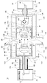
図4は、本実施形態に係る共鳴式非接触給電システム10の構成を模式的に示す図である。また、図5は、本実施形態において特徴的な構成部分について説明するための図である。共鳴式非接触給電システムにおける電力伝送原理については、引用文献1に開示の技術を用いることができるので、ここでは詳細な説明は省略する。
FIG. 4 is a diagram schematically illustrating a configuration of the resonance type non-contact
共鳴式非接触給電システム10は、送電側(一次側)ディバイスとして、高周波電源20と、一次コイル30と、一次共鳴コイル35とを備える。一次コイル30は送電側同軸ケーブル60を用いて高周波電源20に接続されている。より具体的には、高周波電源20は、電源筐体24の内部に発振源22を備え、送電側同軸ケーブル60によって一次コイル30に接続されている。また、電源筐体24はグランドGNDに接地されている。接地の態様については、専用アース線で接地されてもよいし、ACケーブルのFG線等で接地されてもよい。
The resonance-type non-contact
さらに、共鳴式非接触給電システム10は、第1層目のシールド層である送電側金属シールド80を備え、一次コイル30及び一次共鳴コイル35の周囲を覆っている。送電側金属シールド80は、例えば、受電側(二次側;図示右側)が開口88(送電側金属シールド前面側開口88)となっているスチール製や銅製の良導体金属できたケース状を呈している。つまり、送電側金属シールド80のシールド側面82は、一次コイル30及び一次共鳴コイル35の周囲を送電側金属シールド前面側開口88を除いて完全に覆っている。より具体的には、一次共鳴コイル35は、送電側金属シールド80の内部に完全に収容されている。言い換えると、図示において、一次共鳴コイル35の最前部(図示右側)は、送電側金属シールド前面側開口88より内側(図示左側)になるような形状及び配置となっている。なお、送電側金属シールド前面側開口88は、樹脂材のような絶縁性のフタ材によって塞がれる構成であってもよい。
Furthermore, the resonance-type non-contact
また、送電側金属シールド80のシールド底面84には、高周波電源20と一次コイル30との間の伝送路のための伝送用開口(送電側金属シールド底面側開口87)が設けられており、その伝送用開口に送電側同軸ケーブル60が接続されている。より具体的には、送電側同軸ケーブル60の同軸ケーブル外導体64の一方の端部(図示右側)が、送電側金属シールド80のシールド底面84(送電側金属シールド底面側開口87)に接続されている。同軸ケーブル外導体64の他方の端部(図示左側)が、高周波電源20の電源筐体24に接続されている。同軸ケーブル内導体62は、高周波電源20の発振源22と一次コイル30とを直接接続している。
The
さらにまた、共鳴式非接触給電システム10は、第2層目のシールド層として、送電側大型金属シールド120と同軸用金属シールド140とを備えている。
Furthermore, the resonance type non-contact
送電側大型金属シールド120は、送電側金属シールド80を覆うように形成されている。送電側大型金属シールド120は、送電側金属シールド80と同様に良導体の金属であって、例えばケース状の形状を呈し、送電側金属シールド80を覆っている。なお、送電側金属シールド80と送電側大型金属シールド120とは所定距離L31だけ離間した配置構成となっており、送電側金属シールド80と送電側大型金属シールド120の間の空間は、単に離間した状態でもよいし絶縁体が充填されてもよい。また、送電側金属シールド80と送電側大型金属シールド120の開口128(送電側大型金属シールド前面側開口128)部分は絶縁性のフタ体によって塞がれてもよい。
The power transmission side
さらに、送電側大型金属シールド前面側開口128側(受電側;図示右側)端部には、送電側大型金属シールド前面側開口128の端部を外側に拡大する面形状(環状)の大型金属シールド前面部126が形成されている。この大型金属シールド前面部126と、後述の受電側大型金属シールド130の大型金属シールド前面部136とは、面同士を対向して配置される。それらの大きさは、その外端部において電磁界が十分に弱くなるように形成される。
Furthermore, a large-sized metal shield having a surface shape (annular) that expands the end of the power-transmission-side large metal shield front-
また、高周波電源20側に形成されている大型金属シールド底面部124には、送電側大型金属シールド底面側開口127が設けられており、送電側同軸ケーブル60を覆う管状の同軸用金属シールド140の一方の端部が接続されている。同軸用金属シールド140の他方の端部は高周波電源20の電源筐体24に接続されている。送電側同軸ケーブル60と同軸用金属シールド140についても、所定距離離間して配置されている。同軸用金属シールド140は、電気的に送電側大型金属シールド120と電源筐体24とを接続できるものであればよく、例えば、導体管やシールド編組構造の管がある。さらに、同軸用金属シールド140に防水機能等の耐環境性能を持たせるようにしてもよい。
The large metal shield
一方、共鳴式非接触給電システム10は、受電側(二次側)ディバイスとして、負荷装置50と、二次コイル40と、二次共鳴コイル45と、整流器160とを備える。負荷装置50の負荷筐体54の内部には充電池52が設けられる。
On the other hand, the resonance-type non-contact
送電側の送電側金属シールド80と同様に、共鳴式非接触給電システム10は、二次コイル40及び二次共鳴コイル45を覆う受電側金属シールド90と、整流器160を覆う整流器シールド170とを備える。
Similar to the power transmission
具体的には、受電側金属シールド90は、例えば、送電側(一次側;図示左側)が開口98(受電側金属シールド前面側開口98)となっているスチール製や銅製の良導体金属できたケース状を呈している。つまり受電側金属シールド90のシールド側面92は、二次コイル40及び二次共鳴コイル45の周囲を前記の開口を除いて完全に覆っている。
Specifically, the power receiving
また、受電側金属シールド90のシールド底面94には、整流器160と二次コイル40との間の伝送路のための受電側金属シールド底面側開口97が設けられている。
In addition, on the
整流器シールド170は、例えば、スチール製や銅製の良導体金属できた筒状体であって、整流器160を覆うように形成されている。ここでは、整流器シールド170と受電側金属シールド90が、所定に配置されたときに一体の筒状(例えば直方体や円筒)の形状を呈するように構成されている。さらに、整流器シールド170の整流器シールド前面部176と、受電側金属シールド90のシールド底面94とが一体に接続されている。整流器シールド前面部176には、整流器シールド前面側開口178が設けられており、シールド底面94と整流器シールド前面部176が接続した状態で、受電側金属シールド底面側開口97と一致する。その結果、二次コイル40から整流器160への伝送路の為の空間が確保されている。
The
整流器シールド170の整流器シールド底面部174は、後述する受電側大型金属シールド130の大型金属シールド底面部134の内面に接続される。整流器シールド底面部174には、整流器シールド底面側開口177が設けられている。この整流器シールド底面側開口177は、整流器160から充電池52への伝送路の為の空間が確保されている。
The rectifier shield
受電側大型金属シールド130は、受電側金属シールド90や整流器シールド170と同様に良導体の金属であって、例えばケース状の形状を呈し、受電側金属シールド90及び整流器シールド170を覆っている。受電側大型金属シールド130と受電側金属シールド90とは電気的に絶縁状態が維持される構成となっている。
The power-receiving-side
さらに、大型金属シールド側面部132の受電側大型金属シールド前面側開口138の側(送電側;図示左側)端部には、開口端部を外側に拡大する面形状(環状)の大型金属シールド前面部136が形成され、前述の送電側大型金属シールド120の大型金属シールド前面部126と、面同士を対向して配置されている。
Furthermore, the large metal
大型金属シールド底面部134には、受電側大型金属シールド底面側開口137が設けられている。この受電側大型金属シールド底面側開口137は、整流器シールド170が所定の位置に取り付けられたときに、整流器シールド底面側開口177と一致し、整流器160から充電池52への送電線を配設する連通孔(伝送用空間)を構成する。
The power receiving side large metal shield bottom
なお、受電側大型金属シールド130は、車両ボディーと同電位に接続されることから、車両ボディーの一部を構成する形状が利用されてもよいし、独立した構成であってもよい。
Since the power receiving side
出力線シールド70は、受電側大型金属シールド130と負荷装置50とを接続し、整流器160から充電池52への出力線72の外側を覆っている。より具体的には、出力線シールド70の一方の端部は受電側大型金属シールド底面側開口137に接続されており、他方の端部は負荷装置50の負荷筐体54に接続されている。
The
以上の構成による共鳴式非接触給電システム10の動作を簡単に説明する。高周波電源20の発振源22は、例えば数MHz〜数10MHzの高周波を発振し、一次コイル30に供給される。一次共鳴コイル35は一次コイル30の電力を増幅し、二次共鳴コイル45に向けた電磁界を発生させる。二次共鳴コイル45は、一次共鳴コイル35で発生した電磁界と結合し、二次コイル40に誘導電流を生じさせる。誘導電流は、整流器160で直流に変換されて充電池52に供給されることになる。
The operation of the resonance type non-contact
このとき、上述したように従来の共鳴式非接触給電システムの送電側(インフラ側)では、送電側同軸ケーブル60の同軸ケーブル外導体64の内側だけでなく同軸ケーブル外導体64の外側をも通じて接地GNDに誘導電流が流れ込むことから、送電側同軸ケーブル60の周囲に放射電磁界が発生していた。共鳴式非接触給電システムの受電側では、二次共鳴コイルからの電磁界の全てが二次コイルと結合せずに、一部の電磁界が伝送線(出力線)や整流器などと結合し伝送損失となる誘導電流を発生させ、その結果、それらの周囲に放射電磁界を発生させていた。
At this time, as described above, on the power transmission side (infrastructure side) of the conventional resonant contactless power feeding system, not only the inner side of the coaxial cable
しかし、本実施形態において、まず送電側(インフラ側)の装置にあっては、送電側同軸ケーブル60内への伝送エネルギーの収集が向上している。送電電力供給線として同軸線である送電側同軸ケーブル60を用いているので、送電電力を効率よく伝送し、損失低減を実現できる。
However, in this embodiment, first, in the apparatus on the power transmission side (infrastructure side), collection of transmission energy into the power transmission side
また、送電側(一次側)の共鳴部(一次コイル30及び一次共鳴コイル35)の周囲を第1層目のシールド構造である送電側金属シールド80で覆い、送電側金属シールド80と送電側同軸ケーブル60の同軸ケーブル外導体64を電気的に接続しているので、送電側の同軸ケーブル外導体64の外側に流れ出ていた電流を同軸ケーブル外導体64の内側に収集することができる。つまり、一次共鳴コイル35から発生する電磁界が同軸ケーブル外導体64の外側と結合することを防止できる。
Further, the power transmission side (primary side) resonance portion (the
さらに、図5の拡大部A1に示すように、送電側同軸ケーブル60の外側に第2層目のシールド構造として、送電側同軸ケーブル60と送電側金属シールド80とを覆う同軸用金属シールド140と送電側大型金属シールド120とが配置されている。なお、拡大部A1では、送電側同軸ケーブル60と同軸用金属シールド140に着目して図示している。このような構成にすることで、送電側同軸ケーブル60から漏洩する電磁界と一次共鳴コイル35から漏洩する電磁界とを閉じこめることができ、放射電磁界を低減することができる。
Further, as shown in the enlarged portion A1 in FIG. 5, a
また、図5の拡大部A2に示すように、電源筐体24と、同軸用金属シールド140と、同軸ケーブル外導体64とが接続され同電位となっている。このような構成によって、同電位面で密閉空間S1を形成し、その中に送電側同軸ケーブル60からの漏洩電磁界と一次共鳴コイル35からの漏洩電磁界を閉じこめることによって、放射電磁界を低減している。
Further, as shown in the enlarged portion A2 in FIG. 5, the
つぎに受電側(車両側)の特徴について説明する。二次共鳴コイル45を覆う受電側金属シールド90によって、二次共鳴コイル45から発生する電磁界が整流器160や整流器160から充電池52へ電力を送電する出力線72と電磁結合することを防止することができる。
Next, features on the power receiving side (vehicle side) will be described. The power receiving
整流器160は、二次共鳴コイル45(二次コイル40)の直近に配置されている。このため、伝送線路による伝送効率低下を防止できる。
The
さらに、図5の拡大領域A3に示すように、受電側金属シールド90と、整流器シールド170と、車両ボディーとが同電位になるように接続されている。この構成によって、同電位面で密閉空間S4を形成し、二次共鳴コイル45や二次コイル40からの放射電磁界を電気的に安定な金属面で囲うことによって電磁界の車両内へ放射を低減できる。さらに、出力線72への電磁結合を防止することができる。
Further, as shown in an enlarged region A3 in FIG. 5, the power receiving
さらにまた、整流器160から充電池52への出力線72が、車両ボディー電位でシールドされている。その結果、整流器160からのリップルノイズが作る電磁界の車両内への放射電磁界を低減することができる。
Furthermore, the
さらに、図5の拡大部A4に示すように、対向する大型金属シールド前面部126、136の間の空間を外径外方向に十分に確保できることから、漏れる電磁界の強さを十分に低減することが可能となる。さらに、送電側金属シールド80のシールド側面82と送電側大型金属シールド120の大型金属シールド側面部122との間の距離L31、受電側金属シールド90のシールド側面92と受電側大型金属シールド130の大型金属シールド側面部132との距離L32とを十分に近づけている。この構成によって、送電側金属シールド前面側開口88と送電側大型金属シールド前面側開口128の間の電磁界、及び、受電側金属シールド90の受電側金属シールド前面側開口98と受電側大型金属シールド130の受電側大型金属シールド前面側開口138との間の電磁界を低減することができる。
Further, as shown in the enlarged portion A4 in FIG. 5, the space between the opposing large metal
以上、本発明を実施形態をもとに説明した。これら実施形態は例示であり、それらの各構成要素及びその組合せにいろいろな変形例が可能なこと、またそうした変形例も本発明の範囲にあることは当業者に理解されるところである。 The present invention has been described based on the embodiments. It is to be understood by those skilled in the art that these embodiments are exemplifications, and that various modifications are possible for each of those components and combinations thereof, and that such modifications are also within the scope of the present invention.
図6にそのような変形例に係る共鳴式非接触給電システム210の一形態を示す。上述の共鳴式非接触給電システム10と異なる点は、まず、共鳴コイルとしてLC発振器が用いられている点にある。具体的には、自己共鳴タイプである一次共鳴コイル35の代わりに送電側LC発振器235が用いられ、二次共鳴コイル45の代わりに受電側LC発振器245が用いられている。なお、共鳴コイルとしては、上述の形態に限る趣旨ではなく、共鳴コイルとして機能するものであればよい。
FIG. 6 shows an embodiment of a resonance type non-contact
つぎに異なる点は、整流器160が受電側金属シールド90aの内部に配置されている点にある。具体的には、整流器160及びそのシールドケースである整流器シールド170が、受電側金属シールド90aの内部に配置されている。そして、受電側金属シールド90aが受電側大型金属シールド130の大型金属シールド底面部134の内面に取り付けられている。このとき、受電側大型金属シールド130、受電側金属シールド90a及び整流器シールド170は、車両ボディーと同電位になっている。このような構成により上述の実施形態同様の効果が得られる。
Next, the difference is that the
10、210 共鳴式非接触給電システム
20 高周波電源
22 発振源
24 電源筐体
30 一次コイル
35 一次共鳴コイル
40 二次コイル
45 二次共鳴コイル
50 負荷装置
52 充電池
54 負荷筐体
60 送電側同軸ケーブル
62 同軸ケーブル内導体
64 同軸ケーブル外導体
70 出力線シールド
72 出力線
80 送電側金属シールド
82、92、92a シールド側面
84、94、94a シールド底面
87 送電側金属シールド底面側開口
88 送電側金属シールド前面側開口
90、90a 受電側金属シールド
97 受電側金属シールド底面側開口
98 受電側金属シールド前面側開口
120 送電側大型金属シールド
122、132 大型金属シールド側面部
124、134 大型金属シールド底面部
126、136 大型金属シールド前面部
127 送電側大型金属シールド底面側開口
128 送電側大型金属シールド前面側開口
130 受電側大型金属シールド
137 受電側大型金属シールド底面側開口
138 受電側大型金属シールド前面側開口
140 同軸用金属シールド
160 整流器
170 整流器シールド
172 整流器シールド側面部
174 整流器シールド底面部
176 整流器シールド前面部
177 整流器シールド底面側開口
178 整流器シールド前面側開口
235 送電側LC発振器
245 受電側LC発振器
DESCRIPTION OF SYMBOLS 10,210 Resonance type non-contact electric power feeding system 20 High frequency power supply 22 Oscillation source 24 Power supply housing 30 Primary coil 35 Primary resonance coil 40 Secondary coil 45 Secondary resonance coil 50 Load device 52 Rechargeable battery 54 Load housing 60 Power transmission side coaxial cable 62 Coaxial cable inner conductor 64 Coaxial cable outer conductor 70 Output line shield 72 Output line 80 Power transmission side metal shield 82, 92, 92a Shield side surface 84, 94, 94a Shield bottom surface 87 Power transmission side metal shield bottom side opening 88 Power transmission side metal shield front surface Side opening 90, 90a Power receiving side metal shield 97 Power receiving side metal shield bottom side opening 98 Power receiving side metal shield front side opening 120 Power transmission side large metal shield 122, 132 Large metal shield side surface 124, 134 Large metal shield bottom surface 126, 136 Large metal shield front 127 Power-receiving large metal shield bottom opening 128 Power transmission large metal shield front opening 130 Power receiving large metal shield 137 Power receiving large metal shield bottom opening 138 Power receiving large metal shield front opening 140 Coaxial metal shield 160 Rectifier 170 Rectifier Shield 172 Rectifier shield side surface portion 174 Rectifier shield bottom surface portion 176 Rectifier shield front surface portion 177 Rectifier shield bottom surface side opening 178 Rectifier shield front surface side opening 235 Power transmission side LC oscillator 245 Power reception side LC oscillator
Claims (5)
前記送電側共鳴コイル部を備えた送電側装置は、
高周波電源と前記送電側共鳴コイル部とを電気的に接続する送電側の同軸ケーブルと、
前記送電側共鳴コイル部を良導体で外側から覆う第1の送電側シールド手段と、
前記送電側の同軸ケーブルと前記第1の送電側シールド手段とを覆う第2の送電側シールド手段と、
を備え、前記送電側の同軸ケーブルの外導体と、前記第1の送電側シールド手段と、前記高周波電源の筐体と、前記第2の送電側シールド手段は、同電位に接続されており、
前記受電側共鳴コイル部を備えた受電側装置は、
前記受電側共鳴コイル部を良導体で外側から覆う第1の受電側シールド手段と、
前記受電側共鳴コイル部で発生した交流電流を直流電流に整流して負荷装置に出力する整流器を良導体で外側から覆う第2の受電側シールド手段と、
前記第1の受電側シールド手段と前記第2の受電側シールド手段とを覆う第3の受電側シールド手段と、
前記整流器から前記負荷装置までの出力線のうち、前記第3の受電側シールド手段から前記負荷装置の筐体までの区間において、前記出力線を覆う出力線シールド手段と、
を備え、前記第1の受電側シールド手段と、前記第2の受電側シールド手段と、前記第3の受電側シールド手段と、前記出力線シールド手段とは、同電位に接続されている
ことを特徴とする共鳴式非接触給電システム。
A resonance type non-contact power feeding system that transmits electric power from a power transmission side resonance coil part to a power reception side resonance coil part by non-contact resonance action,
The power transmission side device provided with the power transmission side resonance coil section is,
A coaxial cable on the power transmission side for electrically connecting a high-frequency power source and the power transmission side resonance coil section;
A first power transmission side shield means for covering the power transmission side resonance coil portion from the outside with a good conductor;
Second power transmission side shielding means for covering the power transmission side coaxial cable and the first power transmission side shielding means;
The outer conductor of the coaxial cable on the power transmission side, the first power transmission shield means, the casing of the high frequency power supply, and the second power transmission shield means are connected to the same potential,
The power receiving side device provided with the power receiving side resonance coil section,
A first power receiving side shielding means for covering the power receiving side resonance coil portion from the outside with a good conductor;
A second power receiving side shield means for covering the rectifier that rectifies the alternating current generated in the power receiving side resonance coil section into a direct current and outputs it to the load device with a good conductor;
A third power receiving shield means for covering the first power receiving shield means and the second power receiving shield means;
Among the output lines from the rectifier to the load device, in the section from the third power receiving side shield means to the housing of the load device, output line shield means for covering the output line;
The first power receiving side shield means, the second power receiving side shield means, the third power receiving side shield means, and the output line shield means are connected to the same potential. Resonant non-contact power feeding system.
前記受電側共鳴コイル部を良導体で外側から覆う第1の受電側シールド手段と、
前記受電側共鳴コイル部で発生した交流電流を直流電流に整流する整流器を良導体で外側から覆う第2の受電側シールド手段と、
前記第1の受電側シールド手段と前記第2の受電側シールド手段とを覆う第3の受電側シールド手段と、
前記整流器から前記充電池までの出力線のうち、前記第3の受電側シールド手段から前記充電池の筐体までの区間において、前記出力線を覆う出力線シールド手段と、
を備え、
前記第1の受電側シールド手段と、前記第2の受電側シールド手段と、前記第3の受電側シールド手段と、前記出力線シールド手段は、車両ボディーと同電位に接続されている ことを特徴とする車載充電装置。
In-vehicle charging in which charging is performed by mounting the power receiving side resonance coil unit and the rechargeable battery in a vehicle by a resonance type non-contact power feeding method that transmits power from the power transmission side resonance coil unit to the power receiving side resonance coil unit by non-contact resonance action. A device,
A first power receiving side shielding means for covering the power receiving side resonance coil portion from the outside with a good conductor;
A second power receiving side shield means for covering a rectifier that rectifies an alternating current generated in the power receiving side resonance coil part into a direct current from the outside with a good conductor;
A third power receiving shield means for covering the first power receiving shield means and the second power receiving shield means;
Among the output lines from the rectifier to the rechargeable battery , in the section from the third power receiving side shield means to the housing of the rechargeable battery , output line shield means for covering the output line;
With
The first power receiving side shield means, the second power receiving side shield means, the third power receiving side shield means, and the output line shield means are connected to the same potential as the vehicle body. In-vehicle charging device.
高周波電源と前記送電側共鳴コイル部とを電気的に接続する送電側の同軸ケーブルと、
前記送電側共鳴コイル部を良導体で外側から覆う第1の送電側シールド手段と、
前記送電側の同軸ケーブルと前記第1の送電側シールド手段とを覆う第2の送電側シールド手段と、
を備え、前記送電側の同軸ケーブルの外導体と、前記第1の送電側シールド手段と、前記高周波電源の筐体と、前記第2の送電側シールド手段は、同電位に接続されている
ことを特徴とする共鳴式非接触給電システムの送電側装置。 In a resonance-type non-contact power feeding system that transmits electric power from a power transmission side resonance coil unit to a power reception side resonance coil unit by non-contact resonance action, a power transmission side device including the power transmission side resonance coil unit,
A coaxial cable on the power transmission side for electrically connecting a high-frequency power source and the power transmission side resonance coil section;
A first power transmission side shield means for covering the power transmission side resonance coil portion from the outside with a good conductor;
Second power transmission side shielding means for covering the power transmission side coaxial cable and the first power transmission side shielding means;
The outer conductor of the coaxial cable on the power transmission side, the first power transmission side shield means, the casing of the high frequency power supply, and the second power transmission side shield means are connected to the same potential. A power transmission side device of a resonance type non-contact power feeding system characterized by the above.
Priority Applications (5)
| Application Number | Priority Date | Filing Date | Title |
|---|---|---|---|
| JP2011096366A JP5690642B2 (en) | 2011-04-22 | 2011-04-22 | Resonance type non-contact power feeding system, power transmission side device of resonance type non-contact power feeding system, and in-vehicle charging device |
| EP12720996.3A EP2700143B1 (en) | 2011-04-22 | 2012-04-20 | Resonance type non-contact power feeding system, power transmission side apparatus and in-vehicle charging apparatus of resonance type non-contact power feeding system |
| PCT/JP2012/061309 WO2012144658A2 (en) | 2011-04-22 | 2012-04-20 | Resonance type non-contact power feeding system, power transmission side apparatus and in-vehicle charging apparatus of resonance type non-contact power feeding system |
| CN201280019811.5A CN103492220B (en) | 2011-04-22 | 2012-04-20 | The power transmission side device of resonance type noncontact feeding power system, resonance type noncontact feeding power system and car charging device |
| US14/110,785 US9426933B2 (en) | 2011-04-22 | 2012-04-20 | Resonance type non-contact power feeding system, power transmission side apparatus and in-vehicle charging apparatus of resonance type non-contact power feeding system |
Applications Claiming Priority (1)
| Application Number | Priority Date | Filing Date | Title |
|---|---|---|---|
| JP2011096366A JP5690642B2 (en) | 2011-04-22 | 2011-04-22 | Resonance type non-contact power feeding system, power transmission side device of resonance type non-contact power feeding system, and in-vehicle charging device |
Publications (2)
| Publication Number | Publication Date |
|---|---|
| JP2012228150A JP2012228150A (en) | 2012-11-15 |
| JP5690642B2 true JP5690642B2 (en) | 2015-03-25 |
Family
ID=46085114
Family Applications (1)
| Application Number | Title | Priority Date | Filing Date |
|---|---|---|---|
| JP2011096366A Active JP5690642B2 (en) | 2011-04-22 | 2011-04-22 | Resonance type non-contact power feeding system, power transmission side device of resonance type non-contact power feeding system, and in-vehicle charging device |
Country Status (5)
| Country | Link |
|---|---|
| US (1) | US9426933B2 (en) |
| EP (1) | EP2700143B1 (en) |
| JP (1) | JP5690642B2 (en) |
| CN (1) | CN103492220B (en) |
| WO (1) | WO2012144658A2 (en) |
Families Citing this family (17)
| Publication number | Priority date | Publication date | Assignee | Title |
|---|---|---|---|---|
| KR101944476B1 (en) * | 2011-07-08 | 2019-02-01 | 오클랜드 유니서비시즈 리미티드 | Interoperability of magnetic structures for inductive power transfer systems |
| JP5718830B2 (en) * | 2012-01-16 | 2015-05-13 | トヨタ自動車株式会社 | vehicle |
| WO2014006895A1 (en) * | 2012-07-05 | 2014-01-09 | パナソニック株式会社 | Wireless power transmission device, wireless power sending device and power receiving device |
| JP6111645B2 (en) * | 2012-12-19 | 2017-04-12 | Tdk株式会社 | Coil device and wireless power transmission system using the same |
| JP2014165997A (en) * | 2013-02-22 | 2014-09-08 | Toshiba Corp | Electromagnetic leakage prevention device and radio power transmission system |
| JP5688549B2 (en) | 2013-04-10 | 2015-03-25 | パナソニック インテレクチュアル プロパティ コーポレーション オブアメリカPanasonic Intellectual Property Corporation of America | Coil module and electronic device |
| US10038342B2 (en) * | 2013-05-15 | 2018-07-31 | Nec Corporation | Power transfer system with shielding body, power transmitting device with shielding body, and power transfer method for power transmitting system |
| TW201500251A (en) * | 2013-06-21 | 2015-01-01 | Hon Hai Prec Ind Co Ltd | Steering wheel and car using the same |
| US11014459B2 (en) * | 2015-09-30 | 2021-05-25 | Volvo Truck Corporation | Charging device for a vehicle |
| JP6832077B2 (en) | 2016-04-28 | 2021-02-24 | 東芝テック株式会社 | Non-contact power transmission device and non-contact power transmission / reception device |
| JP6712489B2 (en) | 2016-04-28 | 2020-06-24 | 東芝テック株式会社 | Non-contact power transmission device and non-contact power transmission/reception device |
| DE102016217795A1 (en) * | 2016-09-16 | 2018-03-22 | Bayerische Motoren Werke Aktiengesellschaft | Coil unit for inductive charging of a vehicle and system |
| JP6649925B2 (en) * | 2017-10-11 | 2020-02-19 | 矢崎総業株式会社 | Power transmission unit |
| DE102019106454A1 (en) * | 2019-03-13 | 2020-09-17 | Zollner Elektronik Ag | Charging arrangement for inductive charging of motor vehicles |
| CN110581010B (en) * | 2019-08-21 | 2022-04-22 | 中航光电科技股份有限公司 | Non-contact connector |
| KR20220109416A (en) * | 2019-12-02 | 2022-08-04 | 고에키자이단호진 후쿠오카켄 산교·가가쿠기쥬츠신코자이단 | Evaporation apparatus, sublimation purification apparatus, production method of organic electronic device and sublimation purification method |
| US11474571B2 (en) * | 2020-05-19 | 2022-10-18 | Samsung Electronics Co., Ltd. | Display panel module and electronic device including multiple display panel modules |
Family Cites Families (16)
| Publication number | Priority date | Publication date | Assignee | Title |
|---|---|---|---|---|
| JP2910529B2 (en) * | 1993-09-20 | 1999-06-23 | 日本電気株式会社 | High frequency signal interface connector and method of mounting the same |
| CN1707905A (en) * | 2004-06-07 | 2005-12-14 | 比亚迪股份有限公司 | Non-contact induction charger |
| JP4962560B2 (en) | 2006-03-21 | 2012-06-27 | 株式会社村田製作所 | Energy carrier with partial influence through a dielectric medium |
| JP4952269B2 (en) * | 2007-01-25 | 2012-06-13 | ミツミ電機株式会社 | Antenna device |
| JP4788693B2 (en) * | 2007-09-26 | 2011-10-05 | セイコーエプソン株式会社 | Structure |
| JP4453741B2 (en) | 2007-10-25 | 2010-04-21 | トヨタ自動車株式会社 | Electric vehicle and vehicle power supply device |
| JP4743244B2 (en) * | 2008-09-18 | 2011-08-10 | トヨタ自動車株式会社 | Non-contact power receiving device |
| EP2330716B1 (en) | 2008-09-19 | 2018-09-05 | Toyota Jidosha Kabushiki Kaisha | Noncontact power receiving apparatus and vehicle including the same |
| JP4962620B2 (en) * | 2008-10-09 | 2012-06-27 | トヨタ自動車株式会社 | Electric vehicle |
| JP5365276B2 (en) | 2009-03-17 | 2013-12-11 | ソニー株式会社 | Power transmission system and power output device |
| JP4909446B2 (en) * | 2009-05-14 | 2012-04-04 | トヨタ自動車株式会社 | Vehicle charging device |
| EP2446520A4 (en) * | 2009-06-25 | 2017-05-03 | Murata Manufacturing Co., Ltd. | Power transfer system and noncontact charging device |
| JP5434330B2 (en) | 2009-07-22 | 2014-03-05 | ソニー株式会社 | Power receiving device, power transmission system, charging device, and power transmission method |
| JP2011029799A (en) * | 2009-07-23 | 2011-02-10 | Sony Corp | Contactless power supplying communication apparatus, contactless power receiving communication device, power-supplying communication control method, and power receiving communication control method |
| WO2011074091A1 (en) * | 2009-12-17 | 2011-06-23 | トヨタ自動車株式会社 | Shield and vehicle whereupon same is mounted |
| US9379780B2 (en) * | 2010-12-16 | 2016-06-28 | Qualcomm Incorporated | Wireless energy transfer and continuous radio station signal coexistence |
-
2011
- 2011-04-22 JP JP2011096366A patent/JP5690642B2/en active Active
-
2012
- 2012-04-20 WO PCT/JP2012/061309 patent/WO2012144658A2/en active Application Filing
- 2012-04-20 CN CN201280019811.5A patent/CN103492220B/en active Active
- 2012-04-20 US US14/110,785 patent/US9426933B2/en active Active
- 2012-04-20 EP EP12720996.3A patent/EP2700143B1/en active Active
Also Published As
| Publication number | Publication date |
|---|---|
| WO2012144658A2 (en) | 2012-10-26 |
| WO2012144658A3 (en) | 2013-06-13 |
| CN103492220A (en) | 2014-01-01 |
| JP2012228150A (en) | 2012-11-15 |
| US20140029233A1 (en) | 2014-01-30 |
| EP2700143B1 (en) | 2017-01-18 |
| EP2700143A2 (en) | 2014-02-26 |
| CN103492220B (en) | 2016-02-03 |
| US9426933B2 (en) | 2016-08-23 |
Similar Documents
| Publication | Publication Date | Title |
|---|---|---|
| JP5690642B2 (en) | Resonance type non-contact power feeding system, power transmission side device of resonance type non-contact power feeding system, and in-vehicle charging device | |
| JP5732307B2 (en) | Resonant contactless power supply system | |
| JP5802424B2 (en) | Resonant contactless power supply system | |
| JP5776703B2 (en) | Vehicle and external power supply device | |
| JP5668676B2 (en) | Power receiving device, vehicle including the same, power transmitting device, and power transmission system | |
| EP2515314B1 (en) | Non-contact power reception device and corresponding transmission device | |
| JP5740200B2 (en) | Resonant non-contact power feeding system, power receiving side device, and power transmitting side device | |
| JP6091262B2 (en) | Power feeding unit, power receiving unit, and power feeding system | |
| WO2013001636A1 (en) | Power transmitting device, power receiving device, and power transmission system | |
| US20140225563A1 (en) | Power transmitting device, vehicle, and power transfer system | |
| WO2015146889A1 (en) | Power reception system | |
| KR101564863B1 (en) | Power transmitting apparatus, power receiving apparatus, and power transmitting system | |
| KR20150012262A (en) | Power reception device and power transmission device | |
| JPWO2012124029A1 (en) | Coil unit, vehicle, external power supply device, and vehicle charging system | |
| KR20150006874A (en) | Vehicle | |
| KR20150003894A (en) | Power reception device, power transmission device, and vehicle | |
| WO2014156014A1 (en) | Contactless charging device | |
| JP2013132171A (en) | Power transmitter, power receiver, and power transmission system | |
| JP2017093141A (en) | Non-contact power transmission device | |
| JP2015089259A (en) | Antenna coil unit | |
| JP6370564B2 (en) | Power receiving unit and power supply system having the same | |
| JP2017093142A (en) | Non-contact power transmission device | |
| JPWO2013001636A1 (en) | Power transmission device, power reception device, and power transmission system |
Legal Events
| Date | Code | Title | Description |
|---|---|---|---|
| A621 | Written request for application examination |
Free format text: JAPANESE INTERMEDIATE CODE: A621 Effective date: 20140318 |
|
| A977 | Report on retrieval |
Free format text: JAPANESE INTERMEDIATE CODE: A971007 Effective date: 20141029 |
|
| A131 | Notification of reasons for refusal |
Free format text: JAPANESE INTERMEDIATE CODE: A131 Effective date: 20141111 |
|
| A521 | Request for written amendment filed |
Free format text: JAPANESE INTERMEDIATE CODE: A523 Effective date: 20141225 |
|
| TRDD | Decision of grant or rejection written | ||
| A01 | Written decision to grant a patent or to grant a registration (utility model) |
Free format text: JAPANESE INTERMEDIATE CODE: A01 Effective date: 20150120 |
|
| A61 | First payment of annual fees (during grant procedure) |
Free format text: JAPANESE INTERMEDIATE CODE: A61 Effective date: 20150202 |
|
| R150 | Certificate of patent or registration of utility model |
Ref document number: 5690642 Country of ref document: JP Free format text: JAPANESE INTERMEDIATE CODE: R150 |
|
| R250 | Receipt of annual fees |
Free format text: JAPANESE INTERMEDIATE CODE: R250 |
|
| R250 | Receipt of annual fees |
Free format text: JAPANESE INTERMEDIATE CODE: R250 |
|
| R250 | Receipt of annual fees |
Free format text: JAPANESE INTERMEDIATE CODE: R250 |
|
| R250 | Receipt of annual fees |
Free format text: JAPANESE INTERMEDIATE CODE: R250 |
|
| R250 | Receipt of annual fees |
Free format text: JAPANESE INTERMEDIATE CODE: R250 |
|
| R250 | Receipt of annual fees |
Free format text: JAPANESE INTERMEDIATE CODE: R250 |
|
| S531 | Written request for registration of change of domicile |
Free format text: JAPANESE INTERMEDIATE CODE: R313531 |
|
| R350 | Written notification of registration of transfer |
Free format text: JAPANESE INTERMEDIATE CODE: R350 |
|
| R250 | Receipt of annual fees |
Free format text: JAPANESE INTERMEDIATE CODE: R250 |