JP5689073B2 - Ultrasonic diagnostic apparatus and three-dimensional elastic ratio calculation method - Google Patents
Ultrasonic diagnostic apparatus and three-dimensional elastic ratio calculation method Download PDFInfo
- Publication number
- JP5689073B2 JP5689073B2 JP2011541897A JP2011541897A JP5689073B2 JP 5689073 B2 JP5689073 B2 JP 5689073B2 JP 2011541897 A JP2011541897 A JP 2011541897A JP 2011541897 A JP2011541897 A JP 2011541897A JP 5689073 B2 JP5689073 B2 JP 5689073B2
- Authority
- JP
- Japan
- Prior art keywords
- elastic
- dimensional
- elasticity
- interest
- ratio
- Prior art date
- Legal status (The legal status is an assumption and is not a legal conclusion. Google has not performed a legal analysis and makes no representation as to the accuracy of the status listed.)
- Expired - Fee Related
Links
Images


Classifications
-
- A—HUMAN NECESSITIES
- A61—MEDICAL OR VETERINARY SCIENCE; HYGIENE
- A61B—DIAGNOSIS; SURGERY; IDENTIFICATION
- A61B8/00—Diagnosis using ultrasonic, sonic or infrasonic waves
- A61B8/13—Tomography
- A61B8/14—Echo-tomography
-
- A—HUMAN NECESSITIES
- A61—MEDICAL OR VETERINARY SCIENCE; HYGIENE
- A61B—DIAGNOSIS; SURGERY; IDENTIFICATION
- A61B8/00—Diagnosis using ultrasonic, sonic or infrasonic waves
- A61B8/08—Detecting organic movements or changes, e.g. tumours, cysts, swellings
-
- A—HUMAN NECESSITIES
- A61—MEDICAL OR VETERINARY SCIENCE; HYGIENE
- A61B—DIAGNOSIS; SURGERY; IDENTIFICATION
- A61B8/00—Diagnosis using ultrasonic, sonic or infrasonic waves
- A61B8/46—Ultrasonic, sonic or infrasonic diagnostic devices with special arrangements for interfacing with the operator or the patient
- A61B8/467—Ultrasonic, sonic or infrasonic diagnostic devices with special arrangements for interfacing with the operator or the patient characterised by special input means
- A61B8/469—Ultrasonic, sonic or infrasonic diagnostic devices with special arrangements for interfacing with the operator or the patient characterised by special input means for selection of a region of interest
-
- A—HUMAN NECESSITIES
- A61—MEDICAL OR VETERINARY SCIENCE; HYGIENE
- A61B—DIAGNOSIS; SURGERY; IDENTIFICATION
- A61B8/00—Diagnosis using ultrasonic, sonic or infrasonic waves
- A61B8/48—Diagnostic techniques
- A61B8/483—Diagnostic techniques involving the acquisition of a 3D volume of data
-
- A—HUMAN NECESSITIES
- A61—MEDICAL OR VETERINARY SCIENCE; HYGIENE
- A61B—DIAGNOSIS; SURGERY; IDENTIFICATION
- A61B8/00—Diagnosis using ultrasonic, sonic or infrasonic waves
- A61B8/48—Diagnostic techniques
- A61B8/485—Diagnostic techniques involving measuring strain or elastic properties
-
- G—PHYSICS
- G01—MEASURING; TESTING
- G01S—RADIO DIRECTION-FINDING; RADIO NAVIGATION; DETERMINING DISTANCE OR VELOCITY BY USE OF RADIO WAVES; LOCATING OR PRESENCE-DETECTING BY USE OF THE REFLECTION OR RERADIATION OF RADIO WAVES; ANALOGOUS ARRANGEMENTS USING OTHER WAVES
- G01S15/00—Systems using the reflection or reradiation of acoustic waves, e.g. sonar systems
- G01S15/88—Sonar systems specially adapted for specific applications
- G01S15/89—Sonar systems specially adapted for specific applications for mapping or imaging
- G01S15/8906—Short-range imaging systems; Acoustic microscope systems using pulse-echo techniques
- G01S15/8993—Three dimensional imaging systems
-
- G—PHYSICS
- G01—MEASURING; TESTING
- G01S—RADIO DIRECTION-FINDING; RADIO NAVIGATION; DETERMINING DISTANCE OR VELOCITY BY USE OF RADIO WAVES; LOCATING OR PRESENCE-DETECTING BY USE OF THE REFLECTION OR RERADIATION OF RADIO WAVES; ANALOGOUS ARRANGEMENTS USING OTHER WAVES
- G01S7/00—Details of systems according to groups G01S13/00, G01S15/00, G01S17/00
- G01S7/52—Details of systems according to groups G01S13/00, G01S15/00, G01S17/00 of systems according to group G01S15/00
- G01S7/52017—Details of systems according to groups G01S13/00, G01S15/00, G01S17/00 of systems according to group G01S15/00 particularly adapted to short-range imaging
- G01S7/52023—Details of receivers
- G01S7/52036—Details of receivers using analysis of echo signal for target characterisation
- G01S7/52042—Details of receivers using analysis of echo signal for target characterisation determining elastic properties of the propagation medium or of the reflective target
-
- G—PHYSICS
- G01—MEASURING; TESTING
- G01S—RADIO DIRECTION-FINDING; RADIO NAVIGATION; DETERMINING DISTANCE OR VELOCITY BY USE OF RADIO WAVES; LOCATING OR PRESENCE-DETECTING BY USE OF THE REFLECTION OR RERADIATION OF RADIO WAVES; ANALOGOUS ARRANGEMENTS USING OTHER WAVES
- G01S7/00—Details of systems according to groups G01S13/00, G01S15/00, G01S17/00
- G01S7/52—Details of systems according to groups G01S13/00, G01S15/00, G01S17/00 of systems according to group G01S15/00
- G01S7/52017—Details of systems according to groups G01S13/00, G01S15/00, G01S17/00 of systems according to group G01S15/00 particularly adapted to short-range imaging
- G01S7/52053—Display arrangements
- G01S7/52057—Cathode ray tube displays
- G01S7/5206—Two-dimensional coordinated display of distance and direction; B-scan display
- G01S7/52063—Sector scan display
-
- A—HUMAN NECESSITIES
- A61—MEDICAL OR VETERINARY SCIENCE; HYGIENE
- A61B—DIAGNOSIS; SURGERY; IDENTIFICATION
- A61B8/00—Diagnosis using ultrasonic, sonic or infrasonic waves
- A61B8/42—Details of probe positioning or probe attachment to the patient
- A61B8/4245—Details of probe positioning or probe attachment to the patient involving determining the position of the probe, e.g. with respect to an external reference frame or to the patient
- A61B8/4254—Details of probe positioning or probe attachment to the patient involving determining the position of the probe, e.g. with respect to an external reference frame or to the patient using sensors mounted on the probe
-
- G—PHYSICS
- G01—MEASURING; TESTING
- G01S—RADIO DIRECTION-FINDING; RADIO NAVIGATION; DETERMINING DISTANCE OR VELOCITY BY USE OF RADIO WAVES; LOCATING OR PRESENCE-DETECTING BY USE OF THE REFLECTION OR RERADIATION OF RADIO WAVES; ANALOGOUS ARRANGEMENTS USING OTHER WAVES
- G01S7/00—Details of systems according to groups G01S13/00, G01S15/00, G01S17/00
- G01S7/52—Details of systems according to groups G01S13/00, G01S15/00, G01S17/00 of systems according to group G01S15/00
- G01S7/52017—Details of systems according to groups G01S13/00, G01S15/00, G01S17/00 of systems according to group G01S15/00 particularly adapted to short-range imaging
- G01S7/52085—Details related to the ultrasound signal acquisition, e.g. scan sequences
- G01S7/52087—Details related to the ultrasound signal acquisition, e.g. scan sequences using synchronization techniques
Description
本発明は、超音波診断装置、及び3次元弾性比算出方法に係り、特に、被検体の組織の硬さ又は軟らかさを示す弾性情報の3次元定量化技術に関する。 The present invention relates to an ultrasonic diagnostic apparatus and a three-dimensional elastic ratio calculation method, and more particularly to a three-dimensional quantification technique for elastic information indicating the hardness or softness of a tissue of a subject.
超音波診断装置は、複数の超音波振動子を備えた超音波探触子により被検体内部に超音波を送信し、被検体内部から生体組織の構造に応じた反射エコー信号を受信し、反射エコー信号に基づいて例えばBモード画像等の断層画像を生成して診断用に表示するものである。 The ultrasonic diagnostic device transmits ultrasonic waves to the inside of the subject using an ultrasonic probe having a plurality of ultrasonic transducers, receives a reflected echo signal corresponding to the structure of the living tissue from the inside of the subject, and reflects it. For example, a tomographic image such as a B-mode image is generated based on the echo signal and displayed for diagnosis.
近年、特許文献1に記載されているように、手動又は機械的な方法により超音波探触子で被検体を圧迫しながら超音波受信信号(RF信号)を計測し、断層面の組織の硬さ又は軟らかさを表す弾性画像を生成することが行なわれている。つまり、組織に対する圧迫状態が異なる1対のRF信号のフレームデータに基づいて圧迫により組織各部に生じた変位を求め、求めた変位のフレームデータに基づいて歪み又は弾性率などの弾性情報のフレームデータを演算し、弾性フレームデータに基づいて弾性画像を生成して表示することが行なわれている。 In recent years, as described in Patent Document 1, an ultrasonic reception signal (RF signal) is measured while pressing a subject with an ultrasonic probe by a manual or mechanical method, and the tissue on the tomographic plane is hardened. An elastic image representing the softness or softness is generated. That is, based on the frame data of a pair of RF signals with different compression states on the tissue, the displacement generated in each part of the tissue due to the compression is obtained, and the frame data of elastic information such as strain or elastic modulus based on the obtained frame data of the displacement Is calculated, and an elastic image is generated and displayed based on the elastic frame data.
ところで、組織の変位は圧迫力の大きさによって変わるから、同一部位の組織であっても、強く圧迫すると歪みが大きくなる。そのため、歪みに基づいて生成された弾性画像は、その弾性画像上の各部位の歪みの相対表示を表すに過ぎず、硬さを定量的に評価することができない。 By the way, since the displacement of the tissue changes depending on the magnitude of the compression force, even when the tissue is in the same region, the strain increases when strongly compressed. For this reason, the elasticity image generated based on the strain merely represents the relative display of the strain of each part on the elasticity image, and the hardness cannot be quantitatively evaluated.
この点、特許文献2に記載されているように、被検体のある断層面の弾性画像を表示し、表示された弾性画像上で2つの関心領域(ROI)を設定し、設定された2つの関心領域の弾性情報の2次元弾性比を算出して表示することが知られている。これによれば、2つの関心領域の弾性情報の2次元弾性比を算出して指標値化しているから、圧迫力に関係なく、検者は診断部位の組織の硬さを定量的に評価することができるとされている。
In this regard, as described in
しかしながら、特許文献2の技術は、ある断層面における2次元の弾性情報を定量化することに留まっており、弾性情報を3次元で定量化することについては考慮されていない。
However, the technique of
したがって、特許文献2の技術を用いて、診断部位の組織の硬さを3次元で評価したい場合には、複数の断層面について2つの2次元関心領域をそれぞれ設定する必要がある。しかし、これは操作性の面であまり好ましくはない。
Therefore, when the technique of
そこで本発明は、簡便な操作で被検体の組織の硬さ又は軟らかさを示す弾性情報を3次元で定量化することを課題とする。 Therefore, an object of the present invention is to quantify, in a three-dimensional manner, elasticity information indicating the hardness or softness of a tissue of a subject with a simple operation.
本発明の超音波診断装置は、被検体との間で超音波を送受信する超音波探触子と、該超音波探触子で計測された反射エコー信号に基づいて硬さ又は軟らかさを表す弾性情報を演算して弾性フレームデータを生成する弾性情報演算部と、複数の前記弾性フレームデータに基づいて弾性ボリュームデータを作成する弾性ボリュームデータ作成部と、前記弾性ボリュームデータに基づいて作成された弾性レンダリング画像及び複数断面の弾性スライス画像の少なくとも一方を表示する表示部と、表示された前記弾性レンダリング画像及び複数断面の弾性スライス画像の少なくとも一方を介して複数の3次元関心領域を設定する入力部と、前記弾性レンダリング画像を構成する複数の前記弾性フレームデータにおける第1の3次元関心領域に対応する領域の弾性情報と第2の3次元関心領域に対応する領域の弾性情報との2次元弾性比をそれぞれ算出し、それぞれの前記弾性フレームデータにおける前記2次元弾性比を加算平均して3次元弾性比を算出する3次元弾性比計測部とを備え、前記算出された3次元弾性比を前記表示部に表示することを特徴とする。
The ultrasonic diagnostic apparatus of the present invention expresses hardness or softness based on an ultrasonic probe that transmits / receives ultrasonic waves to / from a subject and a reflected echo signal measured by the ultrasonic probe. An elasticity information calculation unit that calculates elasticity information to generate elasticity frame data, an elasticity volume data creation unit that creates elasticity volume data based on the plurality of elasticity frame data, and an elasticity volume data created based on the elasticity volume data A display unit that displays at least one of an elastic rendering image and an elastic slice image of a plurality of cross sections, and an input for setting a plurality of three-dimensional regions of interest via at least one of the displayed elastic rendering image and an elastic slice image of a plurality of cross sections And a region corresponding to a first three-dimensional region of interest in the plurality of elastic frame data constituting the elastic rendering image 2D elasticity ratio of the elasticity information and the elasticity information of the region corresponding to the second three-dimensional region of interest is calculated, a 3-dimensional elastic ratio by averaging the 2-dimensional elastic ratio in each of the elastic frame data A three-dimensional elasticity ratio measuring unit for calculating, and displaying the calculated three-dimensional elasticity ratio on the display unit.
本発明によれば、簡便な操作で被検体の組織の硬さ又は軟らかさを示す弾性情報を3次元で定量化することができる。 According to the present invention, elasticity information indicating the hardness or softness of a tissue of a subject can be quantified in three dimensions by a simple operation.
以下、本発明を適用してなる超音波診断装置、及び弾性情報の3次元定量化方法の実施形態を説明する。なお、以下の説明では、同一機能部品については同一符号を付して重複説明を省略する。 Hereinafter, embodiments of an ultrasonic diagnostic apparatus to which the present invention is applied and a three-dimensional quantification method of elasticity information will be described. In the following description, the same functional parts are denoted by the same reference numerals, and redundant description is omitted.
図1は、本実施形態の超音波診断装置の全体構成を示すブロック図である。図1に示すように、超音波診断装置100には、被検体1に当接させて用いる超音波探触子2と、超音波探触子2を介して被検体1に時間間隔をおいて繰り返し超音波を送信する送信部3と、被検体1から発生する時系列の反射エコー信号を受信する受信部4と、送信部3と受信部4の送信と受信を切り換える制御を行なう超音波送受信制御部5と、受信部4で受信された反射エコー信号を整相加算する整相加算部6が備えられている。
FIG. 1 is a block diagram showing the overall configuration of the ultrasonic diagnostic apparatus of the present embodiment. As shown in FIG. 1, the ultrasonic diagnostic apparatus 100 includes an
超音波探触子2は、矩形又は扇形の複数の振動子を配設して形成されており、被検体1に振動子を介して超音波を送受信する機能を有している。この超音波探触子2は、複数の振動子の配列方向(長軸方向)と直交する方向(短軸方向)に振動子を機械的に振りながら超音波を送受信することができるよう、モータ制御可能に構成されている。また、超音波探触子2は、超音波の送受信と同時に振動子の傾きを計測する位置センサを有しており、振動子の傾きをフレームナンバーとして出力する。なお、超音波探触子2は、複数の振動子が2次元配列され、超音波送受信方向を電子的に制御することができるものでもよい。
The
送信部3は、超音波探触子2の振動子を駆動して超音波を発生させるための送波パルスを生成する。送信部3は、送信される超音波の収束点をある深さに設定する機能を有している。また、受信部4は、超音波探触子2で受信した反射エコー信号について所定のゲインで増幅してRF信号すなわち受信信号を生成するものである。超音波送受信制御部5は、送信部3や受信部4を制御する。
The transmission unit 3 generates a transmission pulse for driving the transducer of the
また、超音波診断装置100には、受信部4で増幅されたRF信号を入力して位相制御し、一点又は複数の収束点に対し超音波ビームを形成してRF信号フレームデータを生成する整相加算部6と、整相加算部6からのRF信号フレームデータを入力してゲイン補正、ログ圧縮、検波、輪郭強調、フィルタ処理等の信号処理を行ない、断層画像データを生成する断層画像構成部7と、断層画像構成部7から出力される断層画像データをフレームナンバーとともに記憶する2次元断層画像記憶部35とが備えられている。
Further, the ultrasonic diagnostic apparatus 100 receives the RF signal amplified by the receiving unit 4 and performs phase control, and forms an ultrasonic beam at one or more convergence points to generate RF signal frame data. A tomographic image configuration that generates tomographic image data by inputting RF signal frame data from the
ここで、本実施形態の超音波診断装置100は、短軸走査位置制御部46を介して短軸方向に機械的に振動子を振りながら超音波を送受信しており、短軸方向の一方の方向又は反対方向のスキャンを行いながら、2次元断層画像記憶部35には、nフレームの断層画像データが格納される。
Here, the ultrasonic diagnostic apparatus 100 according to the present embodiment transmits and receives ultrasonic waves while mechanically swinging the vibrator in the short axis direction via the short axis scanning
フレームナンバーは、複数の振動子の位置(傾き)と断層画像データとを対応付けるものである。短軸方向の一方の方向のスキャンにおける最初のフレームナンバーを“1”とし、最後のフレームナンバーを“n”とする(nは2以上の自然数)。フレームナンバー“1”の断層画像データが最初に2次元断層画像記憶部35に記憶され、次にフレームナンバー“2”の断層画像データが2次元断層画像記憶部35に記憶される。そして、最後にフレームナンバー“n”の断層画像データが2次元断層画像記憶部35に記憶される。
また、短軸方向の反対方向のスキャンにおける最初のフレームナンバーを“n”とし、最後のフレームナンバーを“1”とし、断層画像データが順次2次元断層画像記憶部35に記憶される。The frame number associates the position (tilt) of a plurality of transducers with tomographic image data. The first frame number in the scan in one direction of the minor axis direction is “1”, and the last frame number is “n” (n is a natural number of 2 or more). The tomographic image data with the frame number “1” is first stored in the two-dimensional tomographic
In addition, the first frame number in the scan in the direction opposite to the short axis direction is “n”, the last frame number is “1”, and the tomographic image data is sequentially stored in the two-dimensional tomographic
超音波診断装置100は、2次元断層画像記憶部35に記憶されたnフレーム分の断層画像データを読み出し、スキャン面毎に順次並べて白黒ボリュームデータを作成する断層ボリュームデータ作成部36を備えており、被検体内の断層画像データの集合であるレンダリング用の断層ボリュームデータが構成される。
The ultrasonic diagnostic apparatus 100 includes a tomographic volume
また、超音波診断装置100には、断層ボリュームデータ作成部36から出力されたRΘΦ座標系の断層画像データをXYZ座標系に変換する断層3次元スキャンコンバージョン部37と、断層3次元スキャンコンバージョン部37から出力されたXYZ座標系の断層画像データを、平面に投影して断層レンダリング画像を生成する断層ボリュームレンダリング部38とが備えられている。
Further, the ultrasonic diagnostic apparatus 100 includes a tomographic 3D
具体的には、断層ボリュームレンダリング部38は、断層ボリュームデータの各点(座標)に対応する輝度値と不透明度から各点の画像情報を求める。そして、例えば下記数式による、視線方向の断層ボリュームデータの輝度値と不透明度を深さ方向に演算して濃淡を与えるボリュームレンダリング法を用いて断層レンダリング画像を構成する。
αouti=αini+(1−αini)*αi、
Couti=Cini+ (1−αini)*αi*Ci
ここで、αouti :i番目の不透明度の出力、αini:i番目の不透明度の入力、αi:i番目の不透明度、Couti:i番目の輝度値の出力、Cini:i番目の輝度値の入力、Ci:i番目の輝度値である。Specifically, the tomographic
α outi = α ini + (1−α ini ) * α i ,
C outi = C ini + (1−α ini ) * α i * C i
Where α outi : i-th opacity output, α ini : i-th opacity input, α i : i-th opacity, C outi : i-th luminance value output, C ini : i-th The luminance value of C i is the i-th luminance value.
なお、上記では、ボリュームレンダリング法を用いて断層レンダリング画像を構成したが、各点の画像が視点位置に該当する面に対してなす傾斜角に応じて濃淡を与えるサーフェスレンダリング法や、視点位置からみた対象物の奥行きに応じて濃淡を与えるボクセル法を用いてもよい。 In the above description, the tomographic rendering image is configured using the volume rendering method. However, the surface rendering method that gives the light and shade according to the inclination angle that the image of each point forms with respect to the surface corresponding to the viewpoint position, and the viewpoint position. You may use the voxel method which gives light and shade according to the depth of the seen object.
また、超音波診断装置100には、断層3次元スキャンコンバージョン部37でXYZ座標系に変換された断層ボリュームデータの直交3断面の断層MPR画像を生成する断層スライス画像生成部47が備えられている。断層スライス画像生成部47は、断層MPR画像の他、XYZ座標系に変換された断層ボリュームデータから複数平行に切り出された断層マルチスライス画像を生成する機能も有している。
Further, the ultrasonic diagnostic apparatus 100 includes a tomographic slice
一方、超音波診断装置100には、断層レンダリング画像と後述する弾性レンダリング画像を合成したり、弾性MPR画像又はマルチスライス画像と後述する弾性MPR画像又は弾性マルチスライス画像を合成したり、これらの画像を並列に表示させたり、切替えを行なう切替合成部12と、合成画像等を表示する画像表示器(表示部)13とが備えられている。
On the other hand, in the ultrasonic diagnostic apparatus 100, a tomographic rendering image and an elastic rendering image to be described later are combined, an elastic MPR image or a multi-slice image and an elastic MPR image or an elastic multi-slice image to be described later are combined, or these images are combined. Are displayed in parallel, or a
さらに、超音波診断装置100には、整相加算部6から出力されるRF信号フレームデータを記憶するRF信号フレームデータ記憶部27と、RF信号フレームデータ記憶部27に記憶された少なくとも2つのRF信号フレームデータを選択するRF信号フレームデータ選択部28と、2つのRF信号フレームデータから被検体1の生体組織の変位を計測して変位フレームデータを生成する変位演算部30と、変位計測部30で計測された変位情報から歪み又は弾性率、粘性率などの弾性情報を求めて弾性フレームデータを生成する弾性情報演算部32と、弾性情報演算部32で演算した歪み又は弾性率などの弾性情報から2次元の弾性画像データを構成する弾性画像構成部34とを備えている。
Further, the ultrasonic diagnostic apparatus 100 includes an RF signal frame
また、弾性画像構成部34から出力された2次元弾性画像データを記憶する2次元弾性画像記憶部39と、被検体の複数の断面で生成された複数の2次元弾性画像データから弾性ボリュームデータを生成する弾性ボリュームデータ作成部40と、弾性ボリュームデータ作成部40から出力されたRΘΦ座標系の弾性画像データをXYZ座標系に変換する弾性3次元スキャンコンバージョン部41と、弾性3次元スキャンコンバージョン部41から出力されたXYZ座標系の弾性画像データを、平面に投影して弾性レンダリング画像を生成する弾性ボリュームレンダリング部42を備えている。
Further, the elastic volume data is obtained from the two-dimensional elastic
また、超音波診断装置100には、弾性3次元スキャンコンバージョン部41でXYZ座標系に変換された弾性ボリュームデータの直交3断面のMPR画像を生成する弾性スライス画像生成部48が備えられている。弾性スライス画像生成部48は、弾性MPR画像の他、XYZ座標系に変換された弾性ボリュームデータから複数平行に切り出された弾性マルチスライス画像を生成する機能も有している。
Further, the ultrasonic diagnostic apparatus 100 includes an elastic slice
また、超音波診断装置100には、各構成要素を制御する画像系制御部44と、画像系制御部44に各種入力を行なう入力インターフェース部(入力部)43を備えている。入力インターフェース部43は、キーボードやトラックボール等により構成される。
Further, the ultrasonic diagnostic apparatus 100 includes an image
RF信号フレームデータ記憶部27は、整相加算部6から時系列に生成されるRF信号フレームデータを順次記憶する。そして、変位計測部30は、選択されたフレームナンバー“n”のRF信号フレームデータから1次元或いは2次元相関処理を行って、RF信号フレームデータの各点に対応する生体組織における変位や移動ベクトルすなわち変位の方向と大きさに関する1次元又は2次元変位分布を求める。ここで、移動ベクトルの検出にはブロックマッチング法を用いる。ブロックマッチング法とは、画像を例えばM×M画素からなるブロックに分け、関心領域内のブロックに着目し、着目しているブロックに最も近似しているブロックを前のフレームから探し、これを参照して予測符号化すなわち差分により標本値を決定する処理を行なうものである。
The RF signal frame
弾性情報演算部32は、変位計測部30から出力される計測値、例えば移動ベクトルと、圧力計測部45から出力される圧力値とから画像上の各点(座標)に対応する生体組織の歪みを演算し、弾性情報を生成するものである。このとき、歪みは、生体組織の移動量、例えば、変位を空間微分することによって算出される。また、弾性情報演算部32において弾性率を演算するよう構成されていてもよい。この場合、超音波探触子2の圧力センサ(図示しない。)に接続された圧力計測部45によって取得された圧力情報を弾性情報演算部32に出力する。弾性率は、圧力の変化を歪みの変化で除することによって計算される。
The elasticity
例えば、圧力計測部45により圧力を計測する場合には、変位計測部30により計測された変位をL(X)、圧力計測部45により計測された圧力をP(X)とすると、歪みΔS(X)は、L(X)を空間微分することによって算出することができる。すなわち、ΔS(X)=ΔL(X)/ΔXという式を用いて求められる。また、弾性率のヤング率Ym(X)は、Ym=(ΔP(X))/ΔS(X)という式によって算出される。このヤング率Ymから画像の各点に相当する生体組織の弾性率が求められるので、2次元弾性画像を連続的に得ることができる。なお、ヤング率とは、物体に加えられた単純引張り応力と、引張りに平行に生じる歪みに対する比である。
For example, when the pressure is measured by the
弾性画像構成部34は、算出された弾性値(歪み、弾性率等)に対し、座標平面内におけるスムージング処理、コントラスト最適化処理や、フレーム間における時間軸方向のスムージング処理等の様々な画像処理を行ない、2次元弾性画像データを構成する。
The elasticity
2次元弾性画像記憶部39は、一連のフレームナンバー“1”〜“n”の2次元弾性画像データを記憶する。2次元弾性画像記憶部39には、超音波探触子の短軸方向の一方の方向及び反対方向におけるフレームナンバー“1”〜“n”のRF信号フレームデータが格納される。
The two-dimensional elastic
弾性ボリュームデータ作成部40は、複数の2次元弾性画像データから弾性ボリュームデータを作成する。2次元弾性画像記憶部39に記憶されたnフレーム分の2次元弾性画像データを読み出し、スキャン面毎に順次並べて弾性ボリュームデータを作成する。このように、被検体内の2次元弾性画像データの集合であるレンダリング用の弾性ボリュームデータが構成される。
The elastic volume
弾性ボリュームレンダリング部42は、弾性ボリュームデータの各点に対応する弾性値(歪み、弾性率等のいずれか1つ)と不透明度から各点の画像情報を求め、3次元弾性画像を構成する。例えば下記数式による、視線方向の弾性ボリュームデータの弾性値を深さ方向に演算するボリュームレンダリング法を用いて3次元弾性画像を構成する。なお、この視線方向は、断層ボリュームレンダリング部38のボリュームレンダリング処理等における視線方向と同一方向である。
αouti=αini+(1−αini)×αi、
Eouti=Eini+αi×(1−αini)×Ei
ここで、αouti :i番目の不透明度の出力、αini:i番目の不透明度の入力、αi:i番目の不透明度、Eouti:i番目の弾性値の出力、Eini:i番目の弾性値の入力、Ei:i番目の弾性値である。The elastic
α outi = α ini + (1−α ini ) × α i ,
E outi = E ini + α i × (1−α ini ) × E i
Where α outi : i-th opacity output, α ini : i-th opacity input, α i : i-th opacity, E outi : i-th elasticity output, E ini : i-th The elasticity value of E i is the i-th elasticity value.
また、弾性ボリュームレンダリング部42は、3次元弾性画像を構成する画像情報に光の3原色すなわち赤(R)値、緑(G)値、青(B)値を付与する。弾性ボリュームレンダリング部42は、例えば、歪みが周囲に比べて大きい箇所又は弾性率が小さい箇所に赤色コードを付与し、歪みが周囲に比べて小さい箇所又は弾性率が大きい箇所に青色コードを付与するなどの処理を行なう。
In addition, the elastic
例えば、上記αを0又は1とすることにより、断層レンダリング画像データ又は弾性レンダリング画像データのみを抽出することもできる。画像選択部は、ボリュームメモリ内の断層レンダリング画像データと弾性レンダリング画像データ及び画像処理部の合成画像データのうちから画像表示器13に表示する画像を選択するものである。
For example, by setting α to 0 or 1, it is possible to extract only tomographic rendering image data or elastic rendering image data. The image selection unit selects an image to be displayed on the
切替合成部12は、例えば画像メモリに確保された断層レンダリング画像と弾性レンダリング画像とを合成割合を変更して合成するものである。切替合成部12は、同じ視点位置における断層レンダリング画像と弾性レンダリング画像を画像メモリから読み出す。そして、断層レンダリング画像と弾性レンダリング画像を合成するが、断層レンダリング画像と弾性レンダリング画像はボリュームレンダリング処理等後の画像データであるため、実質的にはそれぞれ2次元的に加算されることとなる。
For example, the
具体的には、例えば下記数式に示すように、各点において、弾性レンダリング画像の赤(R)値、緑(G)値、青(B)値と、断層レンダリング画像の赤(R)値、緑(G)値、青(B)値とをそれぞれ加算する。なお、αは0以上1以下の係数であり、入力インターフェース部43を介して任意に設定することができる。 Specifically, for example, as shown in the following formula, at each point, the red (R) value of the elastic rendering image, the green (G) value, the blue (B) value, and the red (R) value of the tomographic rendering image, Add green (G) value and blue (B) value respectively. Α is a coefficient not less than 0 and not more than 1, and can be arbitrarily set via the input interface unit 43.
(合成画像データR)=α×(弾性レンダリング画像データR)+(1−α)×(断層レンダリング画像データR)、
(合成画像データG)=α×(弾性レンダリング画像データG)+(1−α)×(断層レンダリング画像データG)、
(合成画像データB)=α×(弾性レンダリング画像データB)+(1−α)×(断層レンダリング画像データB)
ところで、本実施形態のように被検体の組織の変位を求めて弾性画像を生成する超音波診断装置100においては、組織の変位は例えば超音波探触子による圧迫力の大きさによって変わる。したがって、同一部位の組織であっても、強く圧迫すると歪みが大きくなる。(Composite image data R) = α × (elastic rendering image data R) + (1−α) × (tomographic rendering image data R),
(Composite image data G) = α × (elastic rendering image data G) + (1−α) × (tomographic rendering image data G),
(Composite image data B) = α × (elastic rendering image data B) + (1−α) × (tomographic rendering image data B)
By the way, in the ultrasonic diagnostic apparatus 100 that generates the elastic image by obtaining the displacement of the tissue of the subject as in the present embodiment, the displacement of the tissue varies depending on the magnitude of the compression force by the ultrasonic probe, for example. Therefore, even if it is the tissue of the same site | part, when it presses strongly, distortion will become large.
そして、被検体のある断層面の弾性画像上で設定された2つの関心領域(ROI)を設定し、設定された2つの関心領域の弾性情報の比を算出することにより、診断部位の弾性情報を指標値化して硬さを定量的に評価する。 Then, by setting the two regions of interest (ROI) set on the elasticity image of the tomographic plane of the subject and calculating the ratio of the elasticity information of the two set regions of interest, the elasticity information of the diagnostic region Is used as an index value to quantitatively evaluate the hardness.
この手法について簡単に説明を行なう。上述のように組織の変位は例えば超音波探触子による圧迫力の大きさによって変わるから、歪み量に基づいて生成された弾性画像は、その弾性画像上の各部位の歪みの相対表示を表すに過ぎず、硬さを定量的に評価することができない。これに対して例えば弾性率(E)は、組織に加わる応力(σ)を歪み(ε)で除したものであり、組織の硬さ又は軟らかさを示す絶対的な値であるから、定量的に評価することができる。 This method will be briefly described. As described above, since the displacement of the tissue varies depending on, for example, the magnitude of the compression force by the ultrasonic probe, the elastic image generated based on the strain amount represents a relative display of the strain of each part on the elastic image. However, the hardness cannot be quantitatively evaluated. On the other hand, for example, the elastic modulus (E) is obtained by dividing the stress (σ) applied to the tissue by the strain (ε), and is an absolute value indicating the hardness or softness of the tissue. Can be evaluated.
上述の手法は、例えば癌組織と思われる箇所と脂肪組織と思われる箇所にそれぞれ関心領域を設定し、2つの関心領域における歪み比を求めるものである。つまり、2つの関心領域が設定された組織のそれぞれの弾性率をE1,E2とした場合、E1=σ1/ε1、E2=σ2/ε2で表される。ここで、同一フレームの組織にはほぼ同等な圧力が印加されていると推定できる、つまりσ1≒σ2と推定できる。上述の手法はこの点を利用して、2つの関心領域における弾性率の比E1/E2を歪み比ε1/ε2を求めることにより推定するものである。In the above-described method, for example, a region of interest is set in each of a portion considered to be a cancer tissue and a portion considered to be a fat tissue, and a distortion ratio in the two regions of interest is obtained. That is, when the elastic moduli of the tissue in which the two regions of interest are set are E 1 and E 2 , E 1 = σ 1 / ε 1 and E 2 = σ 2 / ε 2 . Here, it can be estimated that almost the same pressure is applied to the tissue in the same frame, that is, it can be estimated that σ 1 ≈σ 2 . The above-described method uses this point to estimate the elastic modulus ratio E 1 / E 2 in the two regions of interest by obtaining the strain ratio ε 1 / ε 2 .
本実施形態の超音波診断装置100は、図1に示すように、座標変換部50と、3次元歪み比計測部52などを特徴構成として備えている。3次元歪み比計測部52は、画像表示器13に表示された弾性レンダリング画像等上に入力インターフェース部43を介して第1の3次元関心領域と第2の3次元関心領域が設定されたら、設定された第1の3次元関心領域における弾性情報と第2の3次元関心領域における弾性情報との3次元弾性比を算出する3次元弾性比計測部である。つまり、3次元歪み比計測部52を3次元弾性比計測部と置き換えることができる。
As shown in FIG. 1, the ultrasonic diagnostic apparatus 100 according to the present embodiment includes a coordinate
3次元歪み比計測部52(3次元弾性比計測部)は、弾性レンダリング画像を構成する複数の弾性フレームデータにおいて、第1の3次元関心領域に対応する領域の弾性情報と第2の3次元関心領域に対応する領域の弾性情報との2次元弾性比をそれぞれ算出する。そして、3次元歪み比計測部52(3次元弾性比計測部)は、それぞれの弾性フレームデータにおける2次元弾性比に基づいて3次元弾性比を算出する。具体的には、3次元歪み比計測部52(3次元弾性比計測部)は、それぞれの弾性フレームデータにおいて算出された2次元弾性比を加算平均して3次元弾性比を算出する。 The three-dimensional strain ratio measurement unit 52 (three-dimensional elasticity ratio measurement unit), in a plurality of elasticity frame data constituting the elasticity rendering image, the elasticity information of the region corresponding to the first three-dimensional region of interest and the second three-dimensional A two-dimensional elasticity ratio with the elasticity information of the region corresponding to the region of interest is calculated. Then, the three-dimensional strain ratio measuring unit 52 (three-dimensional elastic ratio measuring unit) calculates a three-dimensional elastic ratio based on the two-dimensional elastic ratio in each elastic frame data. Specifically, the three-dimensional strain ratio measuring unit 52 (three-dimensional elastic ratio measuring unit) calculates the three-dimensional elastic ratio by averaging the two-dimensional elastic ratios calculated in the respective elastic frame data.
また、座標変換部50は、画像表示器13に表示されたXYZ座標系の例えば弾性レンダリング画像上に入力インターフェース部43を介して第1の3次元関心領域と第2の3次元関心領域が設定されたら、各3次元関心領域をXYZ座標系からRΘΦ座標系に変換する座標変換手段である。以下、本実施形態の特徴構成について実施例ごとに詳細に説明する。
(第1の実施例)
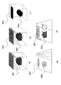
本実施形態の超音波診断装置の弾性情報の3次元弾性比(3次元歪み比)を求める第1の実施例について図2,3を用いて説明する。図2は、第1実施例の弾性情報の3次元歪み比を求めるための処理の概念を示す図である。図3は、第1実施例の処理のフローチャートである。本実施例は、弾性3次元スキャンコンバージョン部41によってXYZ座標系に変換された弾性ボリュームデータに基づいて生成された弾性レンダリング画像を表示して、この弾性レンダリング画像上に2つの関心領域を設定する場合の実施例である。The coordinate
(First embodiment)
A first example for obtaining the three-dimensional elasticity ratio (three-dimensional strain ratio) of the elasticity information of the ultrasonic diagnostic apparatus of this embodiment will be described with reference to FIGS. FIG. 2 is a diagram illustrating a concept of processing for obtaining a three-dimensional strain ratio of elasticity information according to the first embodiment. FIG. 3 is a flowchart of the process of the first embodiment. In this embodiment, an elastic rendering image generated based on the elastic volume data converted into the XYZ coordinate system by the elastic three-dimensional
まず、図2(a)に示すように、画像表示器13には、弾性レンダリング画像201が表示される。検者は、図3(a),図2(b)に示すように、入力インターフェース部43を介して弾性レンダリング画像201上に2つの3次元関心領域202,203を透過もしくは上書きするかして設定する(図3の301)。以下、適宜2つの3次元関心領域202,203のことを、ROI1,ROI2と言う。
First, as shown in FIG. 2 (a), an
続いて、図2(c)に示すように、3次元関心領域202,203は、XYZデータのマスク情報204,205としてデータ化される。そしてマスク情報204,205は、図2(d)に示すように、座標変換部50によってXYZの直交座標系をRΘΦの極座標系に座標変換されて、RΘΦ座標系のROIマスクデータ206,207が作成される(図3の302)。
Subsequently, as shown in FIG. 2 (c), the three-dimensional regions of
3次元歪み比計測部52は、図2(e)に示すように、ROIマスクデータ206,207のオンオフ制御により、RΘΦ座標系における弾性情報ボリュームデータからのXYZ座標系にて設定された3次元関心領域の弾性情報(歪み)を参照可能となる。これにより、RΘΦ座標系に変換されたROIマスクデータ206の弾性情報とROIマスクデータ207の弾性情報とに基づいて3次元弾性比を算出する。
As shown in FIG. 2 (e), the three-dimensional strain
より具体的には、3次元歪み比計測部52は、数1,2式のように、各弾性フレームデータのROI1,ROI2のそれぞれにおいて歪み(平均値)を算出する。そして、数3式のように、ROI1,2間の歪みの比を算出する(図3の303)。これにより、弾性フレームデータ毎に歪み比を算出することができる。最終的には、数4式のように、弾性フレームデータ毎に算出された2次元の歪み比を加算平均することで3次元の歪み比が算出される(図3の304)。算出された3次元の歪み比は、画像表示器13に表示される(図3の305)。
More specifically, the three-dimensional strain

一方、上記説明は図3(a)の際の説明であるが、図3(b)に示すような処理手順を行なってもよい。まず、3次元画像上にROI1,2を設定し(図3の306)、計測ROIマスクをXYZ座標からRΘΦ座標に変換する(図3の307)。 On the other hand, the above description is for FIG. 3 (a), but a processing procedure as shown in FIG. 3 (b) may be performed. First, ROI1 and 2 are set on the three-dimensional image (306 in FIG. 3), and the measurement ROI mask is converted from XYZ coordinates to RΘΦ coordinates (307 in FIG. 3).
続いて、RΘΦ座標系の弾性情報ボリュームデータから各弾性フレームデータの歪み平均値を算出し(図3の308)、各弾性フレームデータのROI1、ROI2から各弾性フレームデータの歪み平均値を加算平均する(図3の309)。最終的に、ROI1、ROI2の歪み平均値の比から歪み比を算出して表示する(図3の310)。この処理手順の場合は、数5,6式により、ROI1,2内の3次元歪み平均値を算出し、数7式により、3次元におけるROI1,2の歪み比平均値を算出する。
Subsequently, the average strain value of each elastic frame data is calculated from the elastic information volume data of the RΘΦ coordinate system (308 in FIG. 3), and the average strain value of each elastic frame data is calculated from the ROI1 and ROI2 of each elastic frame data. (309 in FIG. 3). Finally, the distortion ratio is calculated and displayed from the ratio of the average distortion values of ROI1 and ROI2 (310 in FIG. 3). In the case of this processing procedure, a three-dimensional distortion average value in
ところで、XYZ座標系で表示された弾性レンダリング等上で3次元関心領域が設定された場合、XYZ座標系での例えばXY断面、YZ断面、XZ断面等における弾性情報は必ずしも同様の圧迫状態において生成されたものとはならない。したがって、例えばXY断面、YZ断面、XZ断面等において弾性情報の比を求めると、適正な定量化が図れなくなる。この点、本実施例のように、XYZ座標系の弾性レンダリング画像等上で設定された第1及び第2の3次元関心領域を、XYZ座標系からRΘΦ座標系に変換して、RΘΦ座標系に変換された第1及び第2の3次元関心領域の弾性情報に基づいて3次元弾性比を算出することにより、適正に3次元の弾性情報の定量化を図ることができる。 By the way, when the 3D region of interest is set on the elastic rendering displayed in the XYZ coordinate system, the elasticity information in the XYZ coordinate system, such as the XY section, YZ section, XZ section, etc., is always generated in the same compression state. It will not be done. Therefore, for example, if the ratio of elastic information is obtained in the XY cross section, YZ cross section, XZ cross section, etc., proper quantification cannot be achieved. In this regard, as in this embodiment, the first and second three-dimensional regions of interest set on the elastic rendering image of the XYZ coordinate system are converted from the XYZ coordinate system to the RΘΦ coordinate system, and the RΘΦ coordinate system By calculating the three-dimensional elasticity ratio based on the elasticity information of the first and second three-dimensional regions of interest converted into, the three-dimensional elasticity information can be appropriately quantified.
また本実施例は、弾性レンダリング像を位置情報として計測用のROI1,2を設定する場合の例を説明したが、断層レンダリング像上、もしくは断層像と弾性像を重ね合わせた合成レンダリング像上に計測用のROI1,2を設定するようにしてもよい。
In this embodiment, an example in which the
ここで、座標変換部50によるXYZの直交座標系からRΘΦの極座標系への座標変換について説明しておく。数8式により画面上の座標X、YとMPR用のマトリクスからxiyiziを算出し、それぞれの画素から画面2D座標からXYZ座標に変換する。Here, the coordinate conversion from the orthogonal coordinate system of XYZ to the polar coordinate system of RΘΦ by the coordinate
![]()
![]()
![]()
![]()
![]()
![]()
![]()
![]()
![]()
![]()
![]()
![]()
![]()
![]()
![]()
![]()
![]()
![]()
特に、被検体のスライス位置が異なる複数の断層面の弾性フレームデータを生成するためには、例えば探触子の短軸方向に超音波走査面をモータ制御可能な超音波探触子等を用いて、超音波走査面を短軸方向にスライドしながら超音波送受信を行なう必要がある。一方、上述のように、弾性画像は手動又は機械的な方法により超音波探触子で被検体を圧迫しながら生成される。したがって、被検体の複数の断層面で生成される弾性フレームデータは、それぞれ異なる圧迫状態において生成されることになる。ここで、同一の弾性フレームデータには同様の圧迫力が加わっているから2つの2次元関心領域の弾性情報の比を求めることにより圧迫力の影響を排除でき、その結果弾性情報の定量化が実現できるが、異なる断層面の異なる圧迫状態で生成された2つの弾性フレームデータ相互間で弾性情報の比を求めても適正な定量化は図れない。 In particular, in order to generate elastic frame data of a plurality of tomographic planes having different slice positions of the subject, for example, an ultrasonic probe capable of controlling the ultrasonic scanning plane in the short axis direction of the probe is used. Therefore, it is necessary to perform ultrasonic transmission / reception while sliding the ultrasonic scanning surface in the short axis direction. On the other hand, as described above, the elastic image is generated while pressing the subject with the ultrasonic probe by a manual or mechanical method. Therefore, elastic frame data generated on a plurality of tomographic planes of the subject is generated in different compressed states. Here, since the same compression force is applied to the same elastic frame data, the influence of the compression force can be eliminated by calculating the ratio of the elasticity information of the two two-dimensional regions of interest. As a result, the elasticity information can be quantified. Although it can be realized, proper quantification cannot be achieved even if the ratio of elastic information between two elastic frame data generated in different compressed states on different tomographic planes is obtained.
この点、3次元歪み比計測部52(3次元弾性比計測部)は、弾性レンダリング画像を構成する複数の前記弾性フレームデータにおける第1の3次元関心領域に対応する領域の弾性情報と第2の3次元関心領域に対応する領域の弾性情報との2次元弾性比をそれぞれ算出し、それぞれの弾性フレームデータにおける2次元弾性比に基づいて3次元弾性比を算出する。3次元歪み比計測部52(3次元弾性比計測部)は、それぞれの弾性フレームデータにおいて算出された2次元弾性比を加算平均して3次元弾性比を算出する。 In this regard, the three-dimensional strain ratio measurement unit 52 (three-dimensional elasticity ratio measurement unit) includes the elasticity information of the region corresponding to the first three-dimensional region of interest and the second information in the plurality of elasticity frame data constituting the elasticity rendering image. The two-dimensional elastic ratio with the elastic information of the region corresponding to the three-dimensional region of interest is calculated, and the three-dimensional elastic ratio is calculated based on the two-dimensional elastic ratio in each elastic frame data. The three-dimensional strain ratio measuring unit 52 (three-dimensional elastic ratio measuring unit) calculates the three-dimensional elastic ratio by averaging the two-dimensional elastic ratios calculated in the respective elastic frame data.
これによれば、弾性フレームデータが生成された複数の断層面のそれぞれにおいて弾性情報の比を求めているから、複数の弾性フレームデータがそれぞれ異なる圧迫状態で生成されていたとしても、適正に3次元の弾性情報の定量化を実現することができる。 According to this, since the ratio of the elasticity information is obtained in each of the plurality of tomographic planes on which the elastic frame data is generated, even if the plurality of elastic frame data are generated in different compression states, the 3 Dimensional elasticity information can be quantified.
本発明の超音波診断装置は、より具体的には、弾性ボリュームデータをRΘΦ座標系で生成した場合、弾性ボリュームデータをRΘΦ座標系からXYZ座標系に変換する弾性3次元スキャンコンバージョン部41と、XYZ座標系に変換された弾性ボリュームデータに基づいて弾性レンダリング画像を生成する弾性ボリュームレンダリング部42と、画像表示器13(表示部)に表示されたXYZ座標系の弾性レンダリング画像上に設定された第1の3次元関心領域と第2の3次元関心領域を、XYZ座標系からRΘΦ座標系に変換する座標変換部50とを備えて超音波診断装置を構成し、3次元歪み比計測部52(3次元弾性比計測部)は、RΘΦ座標系に変換された第1の3次元関心領域の弾性情報と第2の3次元関心領域の弾性情報とに基づいて3次元弾性比を算出するよう構成することができる。
More specifically, in the ultrasonic diagnostic apparatus of the present invention, when the elastic volume data is generated in the RΘΦ coordinate system, the elastic three-dimensional
また、RΘΦ座標系で生成された弾性ボリュームデータに基づいて画像表示器13(表示部)に弾性レンダリング画像等の各種画像を表示するためには、RΘΦ座標系の弾性ボリュームデータをXYZ座標系に変換して、XYZ座標系の弾性ボリュームデータに基づいて弾性レンダリング画像等を生成して表示するのが一般的である。ここで、XYZ座標系で表示された弾性レンダリング等上で3次元関心領域が設定された場合、XYZ座標系での例えばXY断面、YZ断面、XZ断面等における弾性情報は必ずしも同様の圧迫状態において生成されたものとはならない。したがって、例えばXY断面、YZ断面、XZ断面等において弾性情報の比を求めると、適正な定量化が図れなくなる。この点、本発明では、XYZ座標系の弾性レンダリング画像等上で設定された第1及び第2の3次元関心領域を、XYZ座標系からRΘΦ座標系に変換して、RΘΦ座標系に変換された第1及び第2の3次元関心領域の弾性情報に基づいて3次元弾性比を算出しているから、適正に3次元の弾性情報の定量化を図ることができる。 In order to display various images such as elastic rendering images on the image display 13 (display unit) based on the elastic volume data generated in the RΘΦ coordinate system, the elastic volume data in the RΘΦ coordinate system is displayed in the XYZ coordinate system. In general, an elastic rendering image or the like is generated and displayed based on the elastic volume data in the XYZ coordinate system after conversion. Here, when the 3D region of interest is set on the elastic rendering displayed in the XYZ coordinate system, etc., the elasticity information in the XYZ coordinate system, such as the XY cross section, YZ cross section, XZ cross section, etc., is not necessarily in the same compression state. It is not generated. Therefore, for example, if the ratio of elastic information is obtained in the XY cross section, YZ cross section, XZ cross section, etc., proper quantification cannot be achieved. In this regard, in the present invention, the first and second three-dimensional regions of interest set on the elastic rendering image of the XYZ coordinate system are converted from the XYZ coordinate system to the RΘΦ coordinate system and converted to the RΘΦ coordinate system. Since the three-dimensional elasticity ratio is calculated based on the elasticity information of the first and second three-dimensional regions of interest, the three-dimensional elasticity information can be appropriately quantified.
より具体的には、3次元歪み比計測部52(3次元弾性比計測部)は、RΘΦ座標系の被検体の組織に対する圧迫状態が同等な複数の断層面のそれぞれにおいて、RΘΦ座標系に変換された第1の3次元関心領域に対応する領域の弾性情報と第2の3次元関心領域に対応する領域の弾性情報との比を算出し、この算出された複数の断層面における2次元弾性比に基づいて3次元弾性比を算出するよう構成することができる。 More specifically, the three-dimensional strain ratio measuring unit 52 (three-dimensional elastic ratio measuring unit) converts the RΘΦ coordinate system to the RΘΦ coordinate system in each of the plurality of tomographic planes in which the compression state on the tissue of the subject is equivalent. The ratio of the elasticity information of the region corresponding to the first three-dimensional region of interest and the elasticity information of the region corresponding to the second three-dimensional region of interest is calculated, and the calculated two-dimensional elasticity in the plurality of tomographic planes A three-dimensional elastic ratio can be calculated based on the ratio.
(第2の実施例)
本実施形態の超音波診断装置の第2の実施例について説明する。本実施例は、弾性スライス画像生成部48が、XYZ座標系に変換された弾性ボリュームデータの直交3断面のMPR画像を生成し、表示されたXYZ座標系のMPR画像上に第1の3次元関心領域と第2の3次元関心領域を設定する点が、第1の実施例と異なる。したがって、第1の実施例と重複する部分については説明を省略する。(Second embodiment)
A second example of the ultrasonic diagnostic apparatus of this embodiment will be described. In this embodiment, the elastic slice
図4は、第2実施例の弾性情報の3次元弾性比(3次元歪み比)を求めるための処理の概念を示す図である。まず、図4(a)に示すように、画像表示器13には、MPR画像401と、弾性レンダリング画像201が表示される。具体的には、画面の4分割された左上、左下、右上の領域に、MPR画像401として、XYZ座標系のXY面、YZ面、XZ面の弾性画像が表示され、画面の右下の領域に、弾性レンダリング画像201が表示される。ただし、弾性レンダリング画像201は表示しなくてもよい。
FIG. 4 is a diagram illustrating a concept of processing for obtaining a three-dimensional elastic ratio (three-dimensional strain ratio) of elastic information according to the second embodiment. First, as shown in FIG. 4 (a), the
検者は、図4(b)に示すように、入力インターフェース部43を介してMPR画像401上に2つの3次元関心領域402,403を設定する。以下、適宜2つの3次元関心領域402,403のことを、ROI1,ROI2と言う。このようにMPR画像上でROI1,2を設定することで、それぞれの断面でのROIの設定状態を確認することができ、例えば、Z方向に細長くなる腫瘍の場合に、ROIを容易に調整することができる。
As shown in FIG. 4B, the examiner sets two three-dimensional regions of
続いて、図4(c)に示すように、3次元関心領域402,403は、XYZデータのマスク情報404,405としてデータ化される。すなわち、図4(b)に示すように、MPR画像上で設定されたROI情報は視覚上において2次元の情報であるが、XYZ座標として管理されるべく情報であり、図4(c)の様なXYZデータのマスク情報として容易にデータ化することができる。続いて、マスク情報404,405は、図4(d)に示すように、座標変換部50によってXYZの直交座標系をRΘΦの極座標系に座標変換されて、RΘΦ座標系のROIマスクデータ406,407が作成される。
Subsequently, as shown in FIG. 4C, the three-dimensional regions of
3次元歪み比計測部52は、図4(e)に示すように、ROIマスクデータ406,407のオンオフ制御により、RΘΦ座標系における弾性情報ボリュームデータからのXYZ座標系にて設定された3次元関心領域の弾性情報(歪み)を参照可能となる。これにより、RΘΦ座標系に変換されたROIマスクデータ406の弾性情報とROIマスクデータ407の弾性情報とに基づいて3次元弾性比を算出する。3次元弾性比の算出の方法は第1実施例と同様である。
As shown in FIG. 4 (e), the three-dimensional strain
本実施例は、弾性MPR像を位置情報として計測用のROI1,2を設定することを例として説明したが、これに限らず、断層MPR像上、もしくは断層像と弾性像を重ね合わせた合成MPR像上で計測用のROI1,2を設定するようにしてもよい。
In this embodiment, the
(第3の実施例)
本実施形態の超音波診断装置の第3の実施例について説明する。本実施例は、弾性スライス画像生成部48が、XYZ座標系に変換された弾性ボリュームデータから複数平行に切り出されたマルチスライス画像(弾性マルチスライス画像)を生成し、表示されたXYZ座標系のマルチスライス画像上に第1の3次元関心領域と第2の3次元関心領域を設定する点が、第1の実施例と異なる。したがって、第1の実施例と重複する部分については説明を省略する。(Third embodiment)
A third example of the ultrasonic diagnostic apparatus of this embodiment will be described. In this embodiment, the elastic slice
図5は、第3実施例の弾性情報の3次元弾性比(3次元歪み比)を求めるための処理の概念を示す図である。まず、図5(a)に示すように、画像表示器13には、弾性マルチスライス画像501が表示される。弾性マルチスライス画像は、3次元に観察する手法の一つであり、XYZ座標系において任意の切断角度における異断面を同時に複数分割画面にて表示できることがメリットである。
FIG. 5 is a diagram illustrating a concept of processing for obtaining a three-dimensional elastic ratio (three-dimensional strain ratio) of elastic information according to the third embodiment. First, as shown in FIG. 5 (a), an elastic
検者は、図5(b)に示すように、入力インターフェース部43を介して弾性マルチスライス画像501上に2つの3次元関心領域502,503を設定する。以下、適宜2つの3次元関心領域502,503のことを、ROI1,ROI2と言う。このように弾性マルチスライス画像501のそれぞれに対してROI1,2を設定することで、例えば、Y方向に直径の変化が大きい腫瘍の場合には、ROIを調整することで、そのスライス面に応じた大きさが容易に設定可能となる。
続いて、図5(c)に示すように、3次元関心領域502,503は、XYZデータのマスク情報504,505としてデータ化される。すなわち、図5(b)に示すように、弾性マルチスライス画像501上で設定されたROI情報は視覚上において2次元の情報であるが、XYZ座標として管理されるべく情報であり、図5(c)の様なXYZデータのマスク情報として容易にデータ化することができる。続いて、マスク情報504,505は、図5(d)に示すように、座標変換部50によってXYZの直交座標系をRΘΦの極座標系に座標変換されて、RΘΦ座標系のROIマスクデータ506,507が作成される。As shown in FIG. 5B, the examiner sets two three-dimensional regions of
Subsequently, as shown in FIG. 5C, the three-dimensional regions of
3次元歪み比計測部52は、図5(e)に示すように、ROIマスクデータ506,507のオンオフ制御により、RΘΦ座標系における弾性情報ボリュームデータからのXYZ座標系にて設定された3次元関心領域の弾性情報(歪み)を参照可能となる。これにより、RΘΦ座標系に変換されたROIマスクデータ506の弾性情報とROIマスクデータ507の弾性情報とに基づいて3次元弾性比を算出する。3次元弾性比の算出の方法は第1実施例と同様である。
As shown in FIG. 5 (e), the three-dimensional strain
本実施例は、弾性マルチスライス像を位置情報として計測用のROI1,2を設定する例を説明したが、これに限らず、例えば断層マルチスライス像上、もしくは断層像と弾性像を重ね合わせた合成マルチスライス像上で計測用のROI1,2を設定するようにしてもよい。
In this embodiment, an example of setting
(第4の実施例)
本実施形態の超音波診断装置の第4の実施例について説明する。本実施例は、座標変換部50によってRΘΦ座標系に変換された第1の3次元関心領域と第2の3次元関心領域をRΘΦ座標系で画像表示器13に表示し、RΘΦ座標系で表示された第1の3次元関心領域及び第2の3次元関心領域の少なくとも一方の3次元関心領域を画像上で調整可能に構成されている点が、第1の実施例と異なる。したがって、第1の実施例と重複する部分については説明を省略する。(Fourth embodiment)
A fourth example of the ultrasonic diagnostic apparatus of this embodiment will be described. In the present embodiment, the first three-dimensional region of interest and the second three-dimensional region of interest converted into the RΘΦ coordinate system by the coordinate
図6は、第4実施例の弾性情報の3次元歪み比を求めるための処理の概念を示す図である。図7は、第4実施例の処理のフローチャートである。まず、図6(a)に示すように、画像表示器13には、弾性レンダリング画像601が表示される。検者は、図7,図6(b)に示すように、入力インターフェース部43を介して弾性レンダリング画像601上に2つの3次元関心領域602,603を透過もしくは上書きするかして設定する(図7の701)。以下、適宜2つの3次元関心領域602,603のことを、ROI1,ROI2と言う。
FIG. 6 is a diagram illustrating a concept of processing for obtaining a three-dimensional strain ratio of elasticity information according to the fourth embodiment. FIG. 7 is a flowchart of the process of the fourth embodiment. First, as shown in FIG. 6A, an
続いて、図6(c)に示すように、3次元関心領域602,603は、XYZデータのマスク情報604,605としてデータ化される。そしてマスク情報604,605は、図6(d)に示すように、座標変換部50によってXYZの直交座標系をRΘΦの極座標系に座標変換されて、RΘΦ座標系のROIマスクデータ606,607が作成される(図7の702)。
Subsequently, as shown in FIG. 6C, the three-dimensional regions of
検者は、図6(e)に示すように、画像表示器13を参照しながら、RΘΦ座標系に変換されたROIマスクデータ606,607をRΘΦの極座標系の画像上で調整する(図7の703)。3次元歪み比計測部52は、図6(e)に示すように、調整されたROIマスクデータ606,607のオンオフ制御により、RΘΦ座標系における弾性情報ボリュームデータからのXYZ座標系にて設定された3次元関心領域の弾性情報(歪み)を参照可能となる。これにより、RΘΦ座標系に変換されて調整されたROIマスクデータ606の弾性情報とROIマスクデータ607の弾性情報とに基づいて3次元弾性比を算出する。
As shown in FIG. 6 (e), the examiner adjusts the
具体的には、ROI1,ROI2のそれぞれにおいて各フレーム内の歪み平均を算出して、ROI1,2間の歪みの比を算出する(図7の704)。これにより、フレームごとの歪み比を算出することができる。最終的には、フレームごとに算出された値を加算平均して3次元の歪み比を算出し(図7の705)、算出された3次元の歪み比は、画像表示器13に表示される(図7の706)。
Specifically, the average distortion within each frame is calculated for each of ROI1 and ROI2, and the distortion ratio between ROI1 and ROI2 is calculated (704 in FIG. 7). As a result, the distortion ratio for each frame can be calculated. Finally, the value calculated for each frame is averaged to calculate a three-dimensional distortion ratio (705 in FIG. 7), and the calculated three-dimensional distortion ratio is displayed on the
(第5の実施例)
本実施形態の超音波診断装置の第5の実施例について説明する。本実施例は、3次元歪み比計測部52が、RΘΦ座標系での被検体の組織に対する圧迫状態の経時的変化に基づいて、第1の3次元関心領域及び第2の3次元関心領域における圧迫状態が同等な区間を検出し、検出された圧迫状態が同等な区間の弾性情報に基づいて3次元弾性比を算出する点が、第1の実施例と異なる。したがって、第1の実施例と重複する部分については説明を省略する。3次元歪み比計測部52(3次元弾性比計測部)は、被検体の組織に対する圧迫状態が同等な複数の弾性フレームデータにおいて、第1の3次元関心領域に対応する領域の弾性情報と第2の3次元関心領域に対応する領域の弾性情報との3次元弾性比を算出する。(Fifth embodiment)
A fifth example of the ultrasonic diagnostic apparatus of this embodiment will be described. In this embodiment, the three-dimensional strain
上述の第1〜第4の実施例で示した方法においては、応力面に沿って歪み比を算出するために、RΘΦ座標系における同じΦ位置に2つのROIが設定される必要があった。これは、圧迫により応力が異なることから、発生する組織歪みが大きく異なることが原因である。本実施例は、RΘΦ座標系における同じΦ位置に2つのROIが設定されない場合に、3次元弾性比を算出する実施例である。 In the methods shown in the first to fourth embodiments described above, it is necessary to set two ROIs at the same Φ position in the RΘΦ coordinate system in order to calculate the strain ratio along the stress surface. This is because the stress is different due to the compression, and the generated tissue strain is greatly different. In the present embodiment, the three-dimensional elastic ratio is calculated when two ROIs are not set at the same Φ position in the RΘΦ coordinate system.
図8は、第5実施例の弾性情報の3次元歪み比を求めるための処理の概念を示す図である。図8(a)は、XYZ座標系におけるYZ面(短軸方向)の断面画像801を示したものである。また、図1に示す圧迫グラフ作成部54は、変位計測部30、弾性情報演算部32,又は圧力計測部45からの出力データを受け取って、図8(b)に示す圧迫グラフ802を作成する。
FIG. 8 is a diagram illustrating a concept of processing for obtaining a three-dimensional strain ratio of elasticity information according to the fifth embodiment. FIG. 8 (a) shows a
圧迫グラフ802を生成することにより、3次元歪み比計測部52は、Φ方向に沿った変位、歪み又は応力の経時変化を把握することができる。3次元歪み比計測部52は、ROI1とROI2の圧迫グラフ同士の相関演算を行なうことにより、ROI1とROI2における圧迫状態が同等な区間(類似区間803)を検出する。そして、検出されたた2つの類似区間803を選定してそれぞれの歪み平均を算出し、それらの比を算出する。3次元弾性比の算出の方法は第1実施例と同様である。
By generating the
これにより、同等な圧迫レベルでの歪み比を比較することが可能となる。また、例えば、短軸方向に参照体(脂肪等個体差の少ない軟らかいもの)と腫瘍(良悪性の腫瘍像形成性病変)の位置が異なる場合、同じフレーム同士で比較するのが困難となる。この点、本実施例によれば、RΘΦ座標系における同じΦ位置に2つのROIが設定されない場合であっても、圧迫状態が同等な区間における歪み比を求めるので、診断部位の硬さ又は軟らかさを的確に定量化することができる。
(第6の実施例)
本実施形態の超音波診断装置の第6の実施例について説明する。本実施例は、3次元歪み比計測部52が、RΘΦ座標系での被検体の組織に対する圧迫状態の経時的変化に基づいて、被検体の組織に対して圧迫が加えられている区間と圧迫が解除されている区間を検出し、第1の3次元関心領域及び第2の3次元関心領域における、圧迫が加えられている区間と圧迫が解除されている区間のいずれか一方のみの弾性情報に基づいて3次元弾性比を算出する点が、第1の実施例と異なる。したがって、第1の実施例と重複する部分については説明を省略する。3次元歪み比計測部52(3次元弾性比計測部)は、被検体の組織に対する圧迫状態の経時的変化に基づいて、被検体の組織に対して圧迫が加えられている区間と圧迫が解除されている区間を検出し、第1の3次元関心領域及び第2の3次元関心領域における、圧迫が加えられている区間と圧迫が解除されている区間のいずれか一方のみの弾性情報に基づいて3次元弾性比を算出する。This makes it possible to compare the distortion ratios at the same compression level. In addition, for example, when the positions of the reference body (soft thing with little individual difference such as fat) and the tumor (benign / malignant tumor image-forming lesion) are different in the minor axis direction, it is difficult to compare the same frames. In this regard, according to the present embodiment, even when two ROIs are not set at the same Φ position in the RΘΦ coordinate system, the strain ratio in the section where the compression state is equivalent is obtained, so the hardness or softness of the diagnostic part is determined. The accuracy can be accurately quantified.
(Sixth embodiment)
A sixth example of the ultrasonic diagnostic apparatus of this embodiment will be described. In the present embodiment, the three-dimensional strain
図9は、第6実施例の弾性情報の3次元歪み比を求めるための処理の概念を示す図である。図9(a)は、XYZ座標系におけるYZ面(短軸方向)の断面画像901を示したものである。また、図1に示す圧迫グラフ作成部54は、変位計測部30、弾性情報演算部32,又は圧力計測部45からの出力データを受け取って、図9(b)に示す圧迫グラフ902を作成する。
FIG. 9 is a diagram showing a concept of processing for obtaining a three-dimensional strain ratio of elasticity information in the sixth embodiment. FIG. 9 (a) shows a
圧迫グラフ902を生成することにより、3次元歪み比計測部52は、Φ方向に沿った変位、歪み又は応力の経時変化を把握することができる。3次元歪み比計測部52は、圧迫グラフ902で示されるROI1とROI2における圧迫状態の経時変化(Φ方向変化)に基づいて、被検体の組織に対して圧迫が加えられている区間と圧迫が解除されている区間を検出する。ここでは、被検体の組織に対して圧迫が加えられている区間を圧迫区間903として検出したとする。3次元歪み比計測部52は、図9(c)に示すように、ROI1とROI2の圧迫区間903における歪み平均を算出し、その比を算出する。3次元弾性比の算出の方法は第1実施例と同様である。
By generating the
本実施例によれば、圧迫の方向を同様なものとすることにより、組織変位による画像のズレによる計測値の劣化を低減することが可能である。したがって、高精度に3次元の歪み比を算出することができる。なお、本実施例は、圧迫が加えられている区間における歪み平均を算出する例を示したが、これに限らず圧迫が解除されている区間における歪み平均を算出するよう構成することもできる。 According to the present embodiment, it is possible to reduce the deterioration of the measurement value due to the image shift due to the tissue displacement by making the compression direction the same. Therefore, the three-dimensional distortion ratio can be calculated with high accuracy. In addition, although the present Example showed the example which calculates the distortion average in the area where the compression is applied, it can also comprise so that the distortion average in the area where the compression is cancelled | released is not restricted to this.
(第7の実施例)
本実施形態の超音波診断装置の第7の実施例について説明する。本実施例は、3次元歪み比計測部52が、RΘΦ座標系での被検体の組織に対する圧迫状態の経時的変化に基づいて、第1の3次元関心領域及び第2の3次元関心領域における弾性情報の積算値を求め、求められた積算値に基づいて被検体の組織に対する圧迫開始位置からの距離を推定し、推定した距離があらかじめ設定された距離閾値よりも大きい又は小さい区間の弾性情報に基づいて3次元弾性比を算出する点が、第1の実施例と異なる。したがって、第1の実施例と重複する部分については説明を省略する。(Seventh embodiment)
A seventh example of the ultrasonic diagnostic apparatus of this embodiment will be described. In this embodiment, the three-dimensional strain
図10は、第7実施例の弾性情報の3次元歪み比を求めるための処理の概念を示す図である。まず、図1に示す圧迫グラフ作成部54は、変位計測部30、弾性情報演算部32,又は圧力計測部45からの出力データを受け取って、図10(a)の上段に示すようにROI1における圧迫グラフ1001を作成する。また、図10(a)の下段に示すように、ROI1における圧迫グラフ1001の圧迫情報を積算して積算グラフ1002を生成する。
FIG. 10 is a diagram showing a concept of processing for obtaining a three-dimensional strain ratio of elasticity information according to the seventh embodiment. First, the compression
一方、圧迫グラフ作成部54は、ROI2についても同様に、図10(b)に示すように、ROI2における圧迫グラフ1003の圧迫情報を積算して積算グラフ1004を生成する。
On the other hand, as shown in FIG. 10 (b), the compression
3次元歪み比計測部52は、積算グラフ1002,1004を参照することにより、超音波探触子の初期圧迫位置からの移動距離を推定することができる。3次元歪み比計測部52は、図10(c)に示すように、積算グラフ1002の積算値が、距離閾値1005よりも小さい区間すなわち初期圧迫位置からの探触子の移動量が小さい区間におけるROI1とROI2の歪み平均を算出し、その比を算出する。3次元弾性比の算出の方法は第1実施例と同様である。
The three-dimensional distortion
本実施例によれば、ROI1,2について圧迫位置が同じレベルのもの同士で比を算出することができるので、計測値の劣化を低減することが可能となる。その結果、高精度に歪み比を検出することができる。なお、本実施例は、積算グラフの積算値が距離閾値よりも小さい区間における歪み平均を算出する例を示したが、これに限らず積算グラフの積算値が距離閾値よりも大きい区間すなわち初期圧迫位置からの探触子の移動量が大きい区間における歪み平均を算出するよう構成することもできる。
According to the present embodiment, since the ratio can be calculated between the
(第8の実施例)
本実施形態の超音波診断装置の第8の実施例について説明する。本実施例は、3次元歪み比計測部52が、RΘΦ座標系での被検体の組織に対する圧迫状態の経時的変化に基づいて、被検体の組織に対して圧迫が加えられている区間と圧迫が解除されている区間を検出し、第1の3次元関心領域及び第2の3次元関心領域における圧迫が加えられている区間又は圧迫が解除されている区間のピークの弾性情報に基づいて3次元弾性比を算出する点が、第1の実施例と異なる。したがって、第1の実施例と重複する部分については説明を省略する。(Eighth embodiment)
An eighth example of the ultrasonic diagnostic apparatus of this embodiment will be described. In the present embodiment, the three-dimensional strain
図11は、第8実施例の弾性情報の3次元歪み比を求めるための処理の概念を示す図である。図11(a)は、XYZ座標系におけるYZ面(短軸方向)の断面画像1101を示したものである。また、図1に示す圧迫グラフ作成部54は、変位計測部30、弾性情報演算部32,又は圧力計測部45からの出力データを受け取って、図9(b)に示す圧迫グラフ1102を作成する。
FIG. 11 is a diagram showing a concept of processing for obtaining a three-dimensional strain ratio of elasticity information according to the eighth embodiment. FIG. 11 (a) shows a
圧迫グラフ1102を生成することにより、3次元歪み比計測部52は、Φ方向に沿った変位、歪み又は応力の経時変化を把握することができる。3次元歪み比計測部52は、圧迫グラフ1102で示されるROI1とROI2における圧迫状態の経時変化(Φ方向変化)に基づいて、被検体の組織に対して圧迫が加えられている区間と圧迫が解除されている区間のピーク1103を検出する。ここでは、被検体の組織に対して圧迫が加えられている区間において圧迫状態がピークになる時相を選択したとする。3次元歪み比計測部52は、図11(c)に示すように、ROI1とROI2それぞれのピーク1103における歪み平均を算出し、その比を算出する。3次元弾性比の算出の方法は第1実施例と同様である。
By generating the
本実施例によれば、弾性情報(歪み)を参照する計測点の数が少なくなるというデメリットはあるが、例えば上述の第6の実施例よりも高精度に3次元の歪み比を計測することができる。なお、本実施例は、圧迫が加えられている区間における圧迫状態のピーク時の歪み平均を算出する例を示したが、これに限らず圧迫が解除されている区間における圧迫状態のピーク時の歪み平均を算出するよう構成することもできる。また、圧迫状態のピークに限らず、入力インターフェース部43を介して例えば圧迫状態が0の位置など任意に歪み平均を算出する位置を選択できるようにしてもよい。 According to the present embodiment, there is a demerit that the number of measurement points referring to elasticity information (strain) is reduced, but for example, it is possible to measure a three-dimensional strain ratio with higher accuracy than the above-described sixth embodiment. Can do. In addition, although the present Example showed the example which calculates the distortion average at the peak of the compression state in the area where the compression is applied, not only this but the peak of the compression state in the area where the compression is released It can also be configured to calculate the strain average. In addition, the position where the distortion average is calculated may be arbitrarily selected via the input interface unit 43, such as a position where the compression state is 0, without being limited to the peak of the compression state.
(第9の実施例)
本実施形態の超音波診断装置の第9の実施例について説明する。本実施例は、3次元歪み比計測部52が、被検体の組織に対する圧迫状態が同等な複数の断層面(弾性フレームデータ)のそれぞれにおいて算出された2次元弾性比のうち、あらかじめ設定された弾性比閾値範囲から外れる2次元弾性比を除外して、残りの複数の断層面における2次元弾性比に基づいて3次元弾性比を算出する点が、第1の実施例と異なる。したがって、第1の実施例と重複する部分については説明を省略する。(Ninth embodiment)
A ninth example of the ultrasonic diagnostic apparatus of this embodiment will be described. In the present embodiment, the three-dimensional strain
図12は、第9実施例の弾性情報の3次元歪み比を求めるための処理の概念を示す図である。図12(a)は、横軸にΦ方向の推移、縦軸に歪み比(SR)をとった2次元歪み比グラフの一例である。図12(a)の2次元歪み比グラフ1201に示すように、3次元の歪み比を算出する際に、Φ方向にノイズ等による異常数値が発生して定量性が低下する場合がある。そこで、3次元歪み比計測部52は、Φ方向に沿って算出された2次元弾性比のうち、あらかじめ設定された弾性比閾値範囲から外れる2次元弾性比を除外する。
FIG. 12 is a diagram illustrating a concept of processing for obtaining the three-dimensional strain ratio of the elasticity information according to the ninth embodiment. FIG. 12 (a) is an example of a two-dimensional strain ratio graph in which the horizontal axis represents the transition in the Φ direction and the vertical axis represents the strain ratio (SR). As shown in the two-dimensional
具体的には、弾性比閾値範囲を定めるために、下記の数23式、数24式により、歪み平均(SRave)と、歪み平均に対する偏差(σ)を算出する。図12(b)に示すように、SRave±σの範囲で示される弾性比閾値範囲1202が決定される。
Specifically, in order to determine the elastic ratio threshold range, the strain average (SRave) and the deviation (σ) with respect to the strain average are calculated by the following equations (23) and (24). As shown in FIG. 12 (b), an elastic
本実施形態の超音波診断装置の第10の実施例について説明する。本実施例は、弾性スライス画像生成部48が、XYZ座標系に変換された弾性ボリュームデータから切り出された1のスライス画像を生成して画像表示器13に表示し、表示されたXYZ座標の1のスライス画像上に入力インターフェース部43を介して複数の関心領域を設定すると、設定された複数の関心領域のそれぞれについて、1のスライス画像に直交する方向の複数のスライス画像上で対応する領域を検出して、設定された関心領域及び検出された複数の領域に基づいて第1の3次元関心領域と第2の3次元関心領域を自動生成する点が、第1の実施例と異なる。したがって、第1の実施例と重複する部分については説明を省略する。
A tenth example of the ultrasonic diagnostic apparatus of this embodiment will be described. In this embodiment, the elastic slice
図13は、第10実施例のROI1,2の自動設定の処理の概念を示す図である。まず、図13(a)に示すように、画像表示器13には、MPR画像1301と、弾性レンダリング画像1302が表示される。具体的には、画面の4分割された左上、左下、右上の領域に、MPR画像1301として、XYZ座標系のXY面、YZ面、XZ面の弾性画像が表示され、画面の右下の領域に、弾性レンダリング画像1302が表示される。ただし、弾性レンダリング画像1302は表示しなくてもよい。
FIG. 13 is a diagram showing a concept of automatic setting processing of
検者は、例えば、MPR画像1301のうちのXY断面の任意のスライス面を選択し、図13(b)に示すように、腫瘍等の関心領域の境界部分を選択点1303により数点選択する(この実施例では4点)。すると、選択点1303を互いに結ぶ選択径に従った内接円が関心領域1304として設定される。続いて、関心領域1304で設定された境界が組織トラッキング法に代表されるような信号追跡手法により、Z方向のスライドした各断面において検出領域1305として検出される。関心領域1304及び複数の検出領域1305をZ軸方向に結ぶことにより、自動的に3次元のROIが生成される。
For example, the examiner selects an arbitrary slice plane of the XY cross section in the
本実施例によれば、検者が1つの断面において関心領域を設定するだけで、自動的に3次元関心領域が設定されるので、装置の使い勝手がよく、診断の効率を向上させることができる。なお、この実施例では説明の便宜のため、1つのROIを設定する例を示したが、実際には、3次元歪み比を算出するために複数(例えば2つ)のROIが設定される。
3次元ROIが設定された後の処理は第1実施例と同様である。According to the present embodiment, the three-dimensional region of interest is automatically set only by the examiner setting the region of interest in one cross section, so that the apparatus is easy to use and the efficiency of diagnosis can be improved. . In this embodiment, for convenience of explanation, an example in which one ROI is set is shown, but actually, a plurality of (for example, two) ROIs are set in order to calculate a three-dimensional distortion ratio.
Processing after the three-dimensional ROI is set is the same as in the first embodiment.
(第11の実施例)
本実施形態の超音波診断装置の第11の実施例について説明する。本実施例は、弾性MPR画像上で2つの関心領域を設定するにあたって、最初に設定された関心領域の位置及び大きさに基づいて、次に関心領域を設定する際に適切な位置に関心領域が設定されるようにガイド表示を行なう点が、第1の実施例と異なる。したがって、第1の実施例と重複する部分については説明を省略する。(Eleventh embodiment)
An eleventh example of the ultrasonic diagnostic apparatus according to this embodiment will be described. In this embodiment, in setting two regions of interest on an elastic MPR image, based on the position and size of the region of interest set first, the region of interest is set at an appropriate position when the region of interest is set next. This is different from the first embodiment in that guide display is performed so that is set. Therefore, the description of the same parts as those in the first embodiment is omitted.
図14は、第11実施例のROIを設定する際のガイド表示の例を示す図である。まず、図14(a)に示すように、画像表示器13には、MPR画像1401と、弾性レンダリング画像1402が表示される。具体的には、画面の4分割された左上、左下、右上の領域に、MPR画像1401として、XYZ座標系のXY面、YZ面、XZ面の弾性画像が表示され、画面の右下の領域に、弾性レンダリング画像1402が表示される。ただし、弾性レンダリング画像1402は表示しなくてもよい。
FIG. 14 is a diagram showing an example of guide display when setting the ROI of the eleventh embodiment. First, as shown in FIG. 14 (a), an
ところで、3次元の歪み比を算出するためには、同フレーム上で2つのROIの設定を行うことが望ましく、3次元計測する際に設定されるROIは、Z座標(時間方向)に対になって設定されることが望ましい。そこで、図14(b)に示すように、MPR画像1401のYZ面上で関心領域を設定する際には、最初に設定された或いは指定されたROI(第1のROI1403)の左右方向の両端の接線をスキャンフレームラインに沿うように延長させて2本のガイドライン1404を表示する。
By the way, in order to calculate the three-dimensional distortion ratio, it is desirable to set two ROIs on the same frame, and the ROI set when measuring three-dimensionally is paired with the Z coordinate (time direction). It is desirable to be set. Therefore, as shown in FIG. 14 (b), when setting the region of interest on the YZ plane of the
検者は、2本のガイドライン1404を参照することにより、これらガイドライン1404に挟まれて、かつガイドライン1404に接するように次のROI(第2のROI1405)を設定すれば良いことを把握することができる。したがって、本実施例によれば、検者は、簡便に、2つの関心領域がZ座標(時間方向)に対に設定することができるので、3次元弾性情報の比を適切に算出できるとともに、装置の使い勝手がよい。
By referring to the two
またこのガイドライン1404の角度を基準に第2のROI1405を自動で設定することもできる。また、設定されたROIの修正は、第1又は第2のいずれかのROIの修正に連動して、他方のROIの大きさを自動変更することもできる。また図14(b)に示すように、YZ面(時間方向)に腫瘍の輪郭に沿ってガイドライン1404を設定する様にすることで、検者の労力を低減することが可能である。
Also, the
1 被検体、2 超音波探触子、6 整相加算部、30 変位計測部、32 弾性情報演算部、34 弾性画像構成部、39 2次元弾性画像記憶部、40 弾性ボリュームデータ作成部、41 弾性3次元スキャンコンバージョン部、42 弾性ボリュームレンダリング部、48 弾性スライス画像生成部、44 画像系制御部、43 入力インターフェース部、50 座標変換部、52 3次元歪み比計測部、100 超音波診断装置、201,601,1302,1402 弾性レンダリング画像、202,203,402,403,502,503,602,603 3次元関心領域、401,1301,1401 MPR画像、501 弾性マルチスライス画像、802,902,1001,1003,1102 圧迫グラフ、803 類似区間、903 圧迫区間、1002,1004 積算グラフ、1005 距離閾値、1103 ピーク、1201 2次元歪み比グラフ、1202 弾性比閾値範囲、1303 選択点、1304 関心領域、1305 検出領域、、、 1 subject, 2 ultrasound probe, 6 phasing addition unit, 30 displacement measurement unit, 32 elasticity information calculation unit, 34 elasticity image configuration unit, 39 2D elasticity image storage unit, 40 elasticity volume data creation unit, 41 Elastic 3D scan conversion unit, 42 Elastic volume rendering unit, 48 Elastic slice image generation unit, 44 Image system control unit, 43 Input interface unit, 50 Coordinate conversion unit, 52 3D strain ratio measurement unit, 100 Ultrasound diagnostic device, 201, 601, 1302, 1402 Elastic rendering image, 202, 203, 402, 403, 502, 503, 602, 603 3D region of interest, 401, 1301, 1401 MPR image, 501 Elastic multi-slice image, 802, 902, 1001 , 1003, 1102 Compression graph, 803 Similar section, 903 Compression section, 1002, 1004 Integration graph, 1005 Distance threshold, 1103 Peak, 1201 Two-dimensional strain ratio graph, 1202 Elastic ratio threshold range, 1303 Selection point, 1304 Region of interest, 1305 Detection area
Claims (10)
前記3次元弾性比計測部は、前記被検体の組織に対する圧迫状態が同等な複数の前記弾性フレームデータにおいて、前記第1の3次元関心領域に対応する領域の弾性情報と前記第2の3次元関心領域に対応する領域の弾性情報との前記3次元弾性比を算出するものであって、The three-dimensional elasticity ratio measurement unit, in the plurality of elastic frame data that is equivalent compression state to the tissue of the subject, elasticity information of the region corresponding to the first three-dimensional region of interest and the second three-dimensional Calculating the three-dimensional elasticity ratio with the elasticity information of the region corresponding to the region of interest,
さらに、前記3次元弾性比計測部は、前記被検体の組織に対する圧迫状態の経時的変化に基づいて、前記被検体の組織に対して圧迫が加えられている区間と圧迫が解除されている区間を検出し、前記第1の3次元関心領域及び前記第2の3次元関心領域における、前記圧迫が加えられている区間と圧迫が解除されている区間のいずれか一方のみの前記弾性情報に基づいて前記3次元弾性比を算出し、前記算出された3次元弾性比を前記表示部に表示することを特徴とする超音波診断装置。Further, the three-dimensional elastic ratio measuring unit is configured to apply a section in which compression is applied to the tissue of the subject and a section in which the compression is released based on a temporal change in the compression state of the subject to the tissue. Based on the elasticity information of only one of the section in which the compression is applied and the section in which the compression is released in the first three-dimensional region of interest and the second three-dimensional region of interest. And calculating the three-dimensional elastic ratio, and displaying the calculated three-dimensional elastic ratio on the display unit.
前記弾性ボリュームデータをRΘΦ座標系で生成した場合、When the elastic volume data is generated in the RΘΦ coordinate system,
前記弾性ボリュームデータをRΘΦ座標系からXYZ座標系に変換する弾性3次元スキャンコンバージョン部と、XYZ座標系に変換された弾性ボリュームデータの直交3断面のMPR画像を生成する弾性スライス画像生成部と、前記表示部に表示されたXYZ座標系のMPR画像上に設定された前記第1の3次元関心領域と前記第2の3次元関心領域を、XYZ座標系からRΘΦ座標系に変換する座標変換部とを備え、An elastic three-dimensional scan conversion unit that converts the elastic volume data from the RΘΦ coordinate system to the XYZ coordinate system; and an elastic slice image generation unit that generates an MPR image of three orthogonal sections of the elastic volume data converted into the XYZ coordinate system; A coordinate conversion unit that converts the first three-dimensional region of interest and the second three-dimensional region of interest set on the MPR image of the XYZ coordinate system displayed on the display unit from the XYZ coordinate system to the RΘΦ coordinate system And
前記3次元弾性比計測部は、前記RΘΦ座標系に変換された第1の3次元関心領域の弾性情報と第2の3次元関心領域の弾性情報とに基づいて前記3次元弾性比を算出し、前記算出された3次元弾性比を前記表示部に表示することを特徴とする超音波診断装置。The three-dimensional elasticity ratio measurement unit calculates the three-dimensional elasticity ratio based on the elasticity information of the first three-dimensional region of interest and the elasticity information of the second three-dimensional region of interest converted into the RΘΦ coordinate system. An ultrasonic diagnostic apparatus that displays the calculated three-dimensional elastic ratio on the display unit.
前記弾性ボリュームデータをRΘΦ座標系で生成した場合、When the elastic volume data is generated in the RΘΦ coordinate system,
前記弾性ボリュームデータをRΘΦ座標系からXYZ座標系に変換する弾性3次元スキャンコンバージョン部と、XYZ座標系に変換された弾性ボリュームデータに基づいて前記弾性レンダリング画像を生成する弾性ボリュームレンダリング部と、前記表示部に表示されたXYZ座標系の弾性レンダリング画像上に設定された前記第1の3次元関心領域と前記第2の3次元関心領域を、XYZ座標系からRΘΦ座標系に変換する座標変換部とを備え、An elastic three-dimensional scan conversion unit that converts the elastic volume data from an RΘΦ coordinate system to an XYZ coordinate system; an elastic volume rendering unit that generates the elastic rendering image based on the elastic volume data converted into the XYZ coordinate system; and A coordinate conversion unit that converts the first three-dimensional region of interest and the second three-dimensional region of interest set on the elastic rendering image of the XYZ coordinate system displayed on the display unit from the XYZ coordinate system to the RΘΦ coordinate system And
前記3次元弾性比計測部は、前記RΘΦ座標系に変換された第1の3次元関心領域の弾性情報と第2の3次元関心領域の弾性情報とに基づいて前記3次元弾性比を算出し、前記算出された3次元弾性比を前記表示部に表示することを特徴とする超音波診断装置。The three-dimensional elasticity ratio measurement unit calculates the three-dimensional elasticity ratio based on the elasticity information of the first three-dimensional region of interest and the elasticity information of the second three-dimensional region of interest converted into the RΘΦ coordinate system. An ultrasonic diagnostic apparatus that displays the calculated three-dimensional elastic ratio on the display unit.
前記3次元弾性比計測部は、前記被検体の組織に対する圧迫状態が同等な複数の断層面のそれぞれにおいて算出された2次元弾性比のうち、あらかじめ設定された弾性比閾値範囲から外れる2次元弾性比を除外して、残りの複数の断層面における2次元弾性比に基づいて前記3次元弾性比を算出し、前記算出された3次元弾性比を前記表示部に表示することを特徴とする超音波診断装置。The three-dimensional elasticity ratio measurement unit is a two-dimensional elasticity that deviates from a preset elasticity ratio threshold range out of the two-dimensional elasticity ratios calculated in each of a plurality of tomographic planes having the same compression state on the tissue of the subject. The three-dimensional elastic ratio is calculated based on the two-dimensional elastic ratio in the remaining plurality of fault planes, excluding the ratio, and the calculated three-dimensional elastic ratio is displayed on the display unit. Ultrasonic diagnostic equipment.
弾性レンダリング画像を構成する複数の前記弾性フレームデータにおける第1の3次元関心領域に対応する領域の弾性情報と第2の3次元関心領域に対応する領域の弾性情報との2次元弾性比をそれぞれ算出するステップと、それぞれの前記弾性フレームデータにおける前記2次元弾性比を加算平均して3次元弾性比を算出するステップを有することを特徴とする3次元弾性比算出方法。The two-dimensional elasticity ratio between the elasticity information of the region corresponding to the first three-dimensional region of interest and the elasticity information of the region corresponding to the second three-dimensional region of interest in the plurality of elastic frame data constituting the elastic rendering image, respectively. A method of calculating a three-dimensional elastic ratio, comprising: calculating and calculating a three-dimensional elastic ratio by averaging the two-dimensional elastic ratios in the respective elastic frame data.
Priority Applications (1)
| Application Number | Priority Date | Filing Date | Title |
|---|---|---|---|
| JP2011541897A JP5689073B2 (en) | 2009-11-18 | 2010-11-11 | Ultrasonic diagnostic apparatus and three-dimensional elastic ratio calculation method |
Applications Claiming Priority (4)
| Application Number | Priority Date | Filing Date | Title |
|---|---|---|---|
| JP2009262705 | 2009-11-18 | ||
| JP2009262705 | 2009-11-18 | ||
| JP2011541897A JP5689073B2 (en) | 2009-11-18 | 2010-11-11 | Ultrasonic diagnostic apparatus and three-dimensional elastic ratio calculation method |
| PCT/JP2010/070078 WO2011062106A1 (en) | 2009-11-18 | 2010-11-11 | Ultrasonic diagnostic device, and method for calculating three-dimensional elastic ratio |
Publications (2)
| Publication Number | Publication Date |
|---|---|
| JPWO2011062106A1 JPWO2011062106A1 (en) | 2013-04-04 |
| JP5689073B2 true JP5689073B2 (en) | 2015-03-25 |
Family
ID=44059585
Family Applications (1)
| Application Number | Title | Priority Date | Filing Date |
|---|---|---|---|
| JP2011541897A Expired - Fee Related JP5689073B2 (en) | 2009-11-18 | 2010-11-11 | Ultrasonic diagnostic apparatus and three-dimensional elastic ratio calculation method |
Country Status (5)
| Country | Link |
|---|---|
| US (1) | US9044175B2 (en) |
| EP (1) | EP2502566A4 (en) |
| JP (1) | JP5689073B2 (en) |
| CN (1) | CN102647946B (en) |
| WO (1) | WO2011062106A1 (en) |
Cited By (1)
| Publication number | Priority date | Publication date | Assignee | Title |
|---|---|---|---|---|
| WO2018139707A1 (en) * | 2017-01-25 | 2018-08-02 | 삼성메디슨 주식회사 | Ultrasonic diagnosis apparatus displaying shear wave data for object and method for operating same |
Families Citing this family (18)
| Publication number | Priority date | Publication date | Assignee | Title |
|---|---|---|---|---|
| JP5951926B2 (en) * | 2010-11-29 | 2016-07-13 | ジーイー・メディカル・システムズ・グローバル・テクノロジー・カンパニー・エルエルシー | Ultrasonic diagnostic apparatus and control program therefor |
| JP5606998B2 (en) * | 2011-07-28 | 2014-10-15 | ジーイー・メディカル・システムズ・グローバル・テクノロジー・カンパニー・エルエルシー | Ultrasonic diagnostic apparatus and control program therefor |
| CA2845404C (en) * | 2011-08-19 | 2020-11-24 | The University Of British Columbia | Elastography using ultrasound imaging of a thin volume |
| WO2013183432A1 (en) * | 2012-06-07 | 2013-12-12 | 日立アロカメディカル株式会社 | Method for setting regions of interest and ultrasonic diagnostic device |
| CN104883978B (en) * | 2012-12-06 | 2017-03-08 | 株式会社日立制作所 | Diagnostic ultrasound equipment and ultrasonic image display method |
| JP2015016144A (en) * | 2013-07-11 | 2015-01-29 | セイコーエプソン株式会社 | Ultrasonic measurement apparatus, ultrasonic imaging apparatus and ultrasonic measurement method |
| CN107427278A (en) * | 2015-01-02 | 2017-12-01 | 百胜集团 | Pass through the elastic method of ultrasound quantification material |
| US10824315B2 (en) * | 2015-05-29 | 2020-11-03 | Canon Medical Systems Corporation | Medical image processing apparatus, magnetic resonance imaging apparatus and medical image processing method |
| US10380786B2 (en) * | 2015-05-29 | 2019-08-13 | General Electric Company | Method and systems for shading and shadowing volume-rendered images based on a viewing direction |
| US10839509B2 (en) | 2015-07-10 | 2020-11-17 | 3Scan Inc. | Spatial multiplexing of histological stains |
| CN114931396A (en) * | 2015-08-10 | 2022-08-23 | 深圳迈瑞生物医疗电子股份有限公司 | Ultrasound elastography system and method |
| KR102545007B1 (en) * | 2015-10-20 | 2023-06-20 | 삼성메디슨 주식회사 | Ultrasound imaging apparatus and controlling method for the same |
| JP6212160B1 (en) * | 2016-04-21 | 2017-10-11 | 株式会社日立製作所 | Ultrasonic diagnostic equipment |
| CN110418609B (en) * | 2017-10-19 | 2021-04-20 | 深圳迈瑞生物医疗电子股份有限公司 | Ultrasonic elasticity measuring device and elasticity comparison measuring method |
| US11576654B2 (en) * | 2017-12-21 | 2023-02-14 | Samsung Medison Co., Ltd. | Ultrasound diagnosis apparatus for measuring and displaying elasticity of object and method of operating the same |
| FI20185410A1 (en) * | 2018-05-03 | 2019-11-04 | Valmet Automation Oy | Measurement of elastic modulus of moving web |
| CN110458836A (en) * | 2019-08-16 | 2019-11-15 | 深圳开立生物医疗科技股份有限公司 | A kind of ultrasonic contrast imaging method, apparatus and equipment and readable storage medium storing program for executing |
| CN110477949B (en) * | 2019-08-26 | 2022-11-29 | 东软医疗系统股份有限公司 | Ultrasonic imaging method and device and ultrasonic imaging equipment |
Citations (6)
| Publication number | Priority date | Publication date | Assignee | Title |
|---|---|---|---|---|
| US20020178833A1 (en) * | 2001-04-04 | 2002-12-05 | Siemens Medical System, Inc | Method and system for improving the spatial resolution for strain imaging |
| WO2006121031A1 (en) * | 2005-05-09 | 2006-11-16 | Hitachi Medical Corporation | Ultrasonograph and ultrasonic image display method |
| JP2007105400A (en) * | 2005-10-17 | 2007-04-26 | Toshiba Corp | Ultrasonic diagnosis device, and image processing device |
| JP3991282B2 (en) * | 2004-08-05 | 2007-10-17 | 株式会社日立メディコ | Elastic image display method and ultrasonic diagnostic apparatus |
| JP2008259555A (en) * | 2007-04-10 | 2008-10-30 | Hitachi Medical Corp | Ultrasonic diagnostic equipment |
| WO2010026823A1 (en) * | 2008-09-08 | 2010-03-11 | 株式会社 日立メディコ | Ultrasound diagnostic apparatus and method of displaying ultrasound image |
Family Cites Families (7)
| Publication number | Priority date | Publication date | Assignee | Title |
|---|---|---|---|---|
| JP3268396B2 (en) | 1992-05-15 | 2002-03-25 | 石原 謙 | Ultrasound diagnostic equipment |
| US7601122B2 (en) * | 2003-04-22 | 2009-10-13 | Wisconsin Alumni Research Foundation | Ultrasonic elastography with angular compounding |
| US9389203B2 (en) * | 2005-06-17 | 2016-07-12 | Wisconsin Alumni Research Foundation | Automated ultrasonic elasticity image formation with quality measure |
| JP5264097B2 (en) * | 2007-04-11 | 2013-08-14 | 株式会社日立メディコ | Ultrasonic diagnostic equipment |
| JP2009045251A (en) | 2007-08-21 | 2009-03-05 | Toshiba Corp | Treatment support equipment |
| US7905835B2 (en) * | 2008-01-15 | 2011-03-15 | General Electric Company | Method for assessing mechanical properties of an elastic material |
| JP4862880B2 (en) * | 2008-11-21 | 2012-01-25 | 株式会社島津製作所 | Structure testing machine |
-
2010
- 2010-11-11 WO PCT/JP2010/070078 patent/WO2011062106A1/en active Application Filing
- 2010-11-11 CN CN201080052221.3A patent/CN102647946B/en not_active Expired - Fee Related
- 2010-11-11 US US13/503,987 patent/US9044175B2/en not_active Expired - Fee Related
- 2010-11-11 EP EP10831501.1A patent/EP2502566A4/en not_active Withdrawn
- 2010-11-11 JP JP2011541897A patent/JP5689073B2/en not_active Expired - Fee Related
Patent Citations (6)
| Publication number | Priority date | Publication date | Assignee | Title |
|---|---|---|---|---|
| US20020178833A1 (en) * | 2001-04-04 | 2002-12-05 | Siemens Medical System, Inc | Method and system for improving the spatial resolution for strain imaging |
| JP3991282B2 (en) * | 2004-08-05 | 2007-10-17 | 株式会社日立メディコ | Elastic image display method and ultrasonic diagnostic apparatus |
| WO2006121031A1 (en) * | 2005-05-09 | 2006-11-16 | Hitachi Medical Corporation | Ultrasonograph and ultrasonic image display method |
| JP2007105400A (en) * | 2005-10-17 | 2007-04-26 | Toshiba Corp | Ultrasonic diagnosis device, and image processing device |
| JP2008259555A (en) * | 2007-04-10 | 2008-10-30 | Hitachi Medical Corp | Ultrasonic diagnostic equipment |
| WO2010026823A1 (en) * | 2008-09-08 | 2010-03-11 | 株式会社 日立メディコ | Ultrasound diagnostic apparatus and method of displaying ultrasound image |
Cited By (1)
| Publication number | Priority date | Publication date | Assignee | Title |
|---|---|---|---|---|
| WO2018139707A1 (en) * | 2017-01-25 | 2018-08-02 | 삼성메디슨 주식회사 | Ultrasonic diagnosis apparatus displaying shear wave data for object and method for operating same |
Also Published As
| Publication number | Publication date |
|---|---|
| CN102647946B (en) | 2014-09-24 |
| EP2502566A4 (en) | 2016-11-23 |
| CN102647946A (en) | 2012-08-22 |
| US20120269416A1 (en) | 2012-10-25 |
| EP2502566A1 (en) | 2012-09-26 |
| JPWO2011062106A1 (en) | 2013-04-04 |
| US9044175B2 (en) | 2015-06-02 |
| WO2011062106A1 (en) | 2011-05-26 |
Similar Documents
| Publication | Publication Date | Title |
|---|---|---|
| JP5689073B2 (en) | Ultrasonic diagnostic apparatus and three-dimensional elastic ratio calculation method | |
| JP5770189B2 (en) | Ultrasonic diagnostic equipment | |
| JP5264097B2 (en) | Ultrasonic diagnostic equipment | |
| JP5730196B2 (en) | Ultrasonic diagnostic apparatus, ultrasonic image processing apparatus, and ultrasonic image generation method | |
| JP4966578B2 (en) | Elastic image generation method and ultrasonic diagnostic apparatus | |
| JP5199690B2 (en) | Ultrasonic diagnostic equipment | |
| KR101121301B1 (en) | Ultrasound system and method of performing 3-dimensional measurement | |
| US9514564B2 (en) | Ultrasonic diagnostic apparatus and ultrasonic image display method | |
| JP5438012B2 (en) | Ultrasonic diagnostic equipment | |
| WO2011030812A1 (en) | Ultrasonic diagnostic device and elasticity image display method | |
| US20110152687A1 (en) | Ultrasonic diagnostic apparatus | |
| WO2010024023A1 (en) | Ultrasound diagnostic apparatus and method of displaying ultrasound image | |
| EP2623035B1 (en) | Ultrasound diagnostic apparatus | |
| US9247922B2 (en) | Ultrasonic diagnostic apparatus and ultrasonic image display method | |
| JP5647990B2 (en) | Ultrasonic diagnostic apparatus and image construction method | |
| JP5156421B2 (en) | Ultrasonic diagnostic equipment | |
| EP2612600A1 (en) | Three-dimensional elastic image generation method and ultrasonic diagnosis device | |
| JP2009039472A (en) | Ultrasonic diagnostic apparatus | |
| JP5074097B2 (en) | Ultrasonic diagnostic equipment | |
| JP4515799B2 (en) | Ultrasonic diagnostic equipment | |
| JP5623609B2 (en) | Ultrasonic diagnostic equipment | |
| JP6230801B2 (en) | Ultrasonic imaging apparatus and ultrasonic image display method |
Legal Events
| Date | Code | Title | Description |
|---|---|---|---|
| A521 | Written amendment |
Free format text: JAPANESE INTERMEDIATE CODE: A523 Effective date: 20131101 |
|
| A621 | Written request for application examination |
Free format text: JAPANESE INTERMEDIATE CODE: A621 Effective date: 20131101 |
|
| A131 | Notification of reasons for refusal |
Free format text: JAPANESE INTERMEDIATE CODE: A131 Effective date: 20140722 |
|
| A521 | Written amendment |
Free format text: JAPANESE INTERMEDIATE CODE: A523 Effective date: 20140818 |
|
| TRDD | Decision of grant or rejection written | ||
| A01 | Written decision to grant a patent or to grant a registration (utility model) |
Free format text: JAPANESE INTERMEDIATE CODE: A01 Effective date: 20150113 |
|
| A61 | First payment of annual fees (during grant procedure) |
Free format text: JAPANESE INTERMEDIATE CODE: A61 Effective date: 20150127 |
|
| R150 | Certificate of patent or registration of utility model |
Ref document number: 5689073 Country of ref document: JP Free format text: JAPANESE INTERMEDIATE CODE: R150 |
|
| S111 | Request for change of ownership or part of ownership |
Free format text: JAPANESE INTERMEDIATE CODE: R313111 |
|
| S533 | Written request for registration of change of name |
Free format text: JAPANESE INTERMEDIATE CODE: R313533 |
|
| R350 | Written notification of registration of transfer |
Free format text: JAPANESE INTERMEDIATE CODE: R350 |
|
| LAPS | Cancellation because of no payment of annual fees |