JP5688552B2 - Camera body and imaging device - Google Patents
Camera body and imaging device Download PDFInfo
- Publication number
- JP5688552B2 JP5688552B2 JP2014001451A JP2014001451A JP5688552B2 JP 5688552 B2 JP5688552 B2 JP 5688552B2 JP 2014001451 A JP2014001451 A JP 2014001451A JP 2014001451 A JP2014001451 A JP 2014001451A JP 5688552 B2 JP5688552 B2 JP 5688552B2
- Authority
- JP
- Japan
- Prior art keywords
- mode
- aperture
- control
- moving image
- exposure
- Prior art date
- Legal status (The legal status is an assumption and is not a legal conclusion. Google has not performed a legal analysis and makes no representation as to the accuracy of the status listed.)
- Active
Links
Images


Classifications
-
- G—PHYSICS
- G03—PHOTOGRAPHY; CINEMATOGRAPHY; ANALOGOUS TECHNIQUES USING WAVES OTHER THAN OPTICAL WAVES; ELECTROGRAPHY; HOLOGRAPHY
- G03B—APPARATUS OR ARRANGEMENTS FOR TAKING PHOTOGRAPHS OR FOR PROJECTING OR VIEWING THEM; APPARATUS OR ARRANGEMENTS EMPLOYING ANALOGOUS TECHNIQUES USING WAVES OTHER THAN OPTICAL WAVES; ACCESSORIES THEREFOR
- G03B7/00—Control of exposure by setting shutters, diaphragms or filters, separately or conjointly
- G03B7/08—Control effected solely on the basis of the response, to the intensity of the light received by the camera, of a built-in light-sensitive device
- G03B7/081—Analogue circuits
- G03B7/085—Analogue circuits for control of aperture
Landscapes
- Physics & Mathematics (AREA)
- General Physics & Mathematics (AREA)
- Studio Devices (AREA)
- Exposure Control For Cameras (AREA)
- Structure And Mechanism Of Cameras (AREA)
- Indication In Cameras, And Counting Of Exposures (AREA)
Description
本発明は、被写体を撮像して画像データを生成する撮像装置に関し、特に、絞りを自動調整可能な撮像装置に関する。 The present invention relates to an imaging apparatus that captures an image of a subject and generates image data, and more particularly to an imaging apparatus capable of automatically adjusting an aperture.
特許文献1には、交換レンズが装着可能なカメラ本体が開示されている。このカメラ本体は、交換レンズに接続可能な中間アダプタが装着可能であり、中間アダプタを装着して被写体像を撮像し、画像データを順次生成する際、順次生成される画像データ間で円滑なAE制御を可能にする。具体的には、カメラ本体は、中間アダプタに対して、目標の映像信号レベルと、検出映像信号レベルとを送信する。中間アダプタは、目標の映像信号レベルと検出映像信号レベルの差に応じて、交換レンズの絞りの駆動量および駆動速度を決定する。その後、中間アダプタは、交換レンズに対して、この駆動量および駆動速度を送信する。これによって、交換レンズは、この受信した駆動量および駆動速度で絞りを制御することで、画像データ間で輝度の変化の少ない円滑な露出制御を可能にしている。 Patent Document 1 discloses a camera body to which an interchangeable lens can be attached. This camera body can be attached with an intermediate adapter that can be connected to an interchangeable lens. When the intermediate adapter is attached to capture a subject image and sequentially generate image data, smooth AE is performed between the sequentially generated image data. Allows control. Specifically, the camera body transmits a target video signal level and a detected video signal level to the intermediate adapter. The intermediate adapter determines the driving amount and driving speed of the stop of the interchangeable lens according to the difference between the target video signal level and the detected video signal level. Thereafter, the intermediate adapter transmits this drive amount and drive speed to the interchangeable lens. Accordingly, the interchangeable lens controls the aperture with the received driving amount and driving speed, thereby enabling smooth exposure control with little change in luminance between image data.
ところで、動画像撮影時に急激に露出が制御されると、撮影された動画像の輝度がフレーム間で急激に変化し、このため、撮影された動画像は使用者にとって違和感のある画像となる。 By the way, when the exposure is suddenly controlled at the time of moving image shooting, the luminance of the shot moving image changes abruptly between frames, so that the shot moving image becomes an image that is uncomfortable for the user.
本発明は、適切な露出制御を行い、使用者にとって好ましい動画像を撮影可能な撮像装置を提供することを目的とする。 An object of the present invention is to provide an imaging apparatus that can perform appropriate exposure control and can capture a moving image that is preferable for a user.
本発明の第1の態様において、交換レンズが装着可能なカメラ本体が提供される。カメラ本体は、交換レンズの絞りの絞り値と、絞りの駆動速度とを設定する制御手段と、制御手段により設定された絞り値及び駆動速度に制御するための制御信号を前記交換レンズに送信する送信手段と、自動的に露光を制御する複数の露出モードから1つの露出モードを設定する設定手段とを備える。制御手段は、動画撮影時において、絞り値を設定された絞り値に変更する際に、設定された露出モードに応じて、絞りの駆動制御の回数を調整する。複数の露出モードは、動画像表示中に絞りのみを自動的に調整する第1モードと、第1モードとは異なる第2モードとを含む。設定手段により第1モードが設定されたときに、制御手段は、第1モードが設定されたときの絞りの駆動制御の回数を、第2モードが設定されたときの絞りの駆動制御の回数よりも多くなるように、絞りの駆動制御の回数を調整する。 In a first aspect of the present invention, a camera body to which an interchangeable lens can be attached is provided. The camera body transmits to the interchangeable lens a control means for setting the aperture value of the aperture of the interchangeable lens and the drive speed of the aperture, and a control signal for controlling the aperture value and the drive speed set by the control means. Transmission means and setting means for setting one exposure mode from a plurality of exposure modes for automatically controlling exposure. The control unit adjusts the number of times of aperture drive control according to the set exposure mode when changing the aperture value to the set aperture value during moving image shooting. The plurality of exposure modes include a first mode in which only the aperture is automatically adjusted during moving image display, and a second mode different from the first mode. When the first mode is set by the setting means, the control means determines the number of times of aperture drive control when the first mode is set from the number of times of aperture drive control when the second mode is set. The number of aperture drive controls is adjusted so that the number of apertures increases.
本発明の第2の態様において、絞りを有する光学系と、絞りを駆動する絞り駆動手段と、絞りの絞り値と絞りの駆動速度とを設定する制御手段と、自動的に露光を制御する複数の露出モードから1つの露出モードを設定する設定手段とを備える撮像装置が提供される。制御手段は、動画撮影時において、絞り値を設定された絞り値に変更する際に、設定された露出モードに応じて、絞りの駆動制御の回数を調整する。複数の露出モード露出モードは、動画像表示中に絞りのみを自動的に調整する第1モードと、第1モードとは異なる第2モードとを含む。設定手段により第1モードが設定されたときに、制御手段は、第1モードが設定されたときの絞りの駆動制御の回数を、第2モードが設定されたときの絞りの駆動制御の回数よりも多くなるように、絞りの駆動制御の回数を調整する。 In the second aspect of the present invention, an optical system having an aperture, aperture driving means for driving the aperture, control means for setting the aperture value of the aperture and the driving speed of the aperture, and a plurality of units for automatically controlling exposure An imaging apparatus is provided that includes setting means for setting one exposure mode from the exposure modes. The control unit adjusts the number of times of aperture drive control according to the set exposure mode when changing the aperture value to the set aperture value during moving image shooting. The plurality of exposure modes include a first mode in which only the aperture is automatically adjusted during moving image display, and a second mode different from the first mode. When the first mode is set by the setting means, the control means determines the number of times of aperture drive control when the first mode is set from the number of times of aperture drive control when the second mode is set. The number of aperture drive controls is adjusted so that the number of apertures increases.
本発明によれば、露出制御のために絞りのみを自動調整するモードにおいて、動画撮像時の露出の急激な変化を防止できる。よって、動画のフレーム間で急激な輝度の変化が生じず、使用者にとって好ましい動画像を得ることができる。 According to the present invention, it is possible to prevent an abrupt change in exposure during moving image capturing in a mode in which only the aperture is automatically adjusted for exposure control. Therefore, a sudden change in luminance does not occur between the frames of the moving image, and a moving image preferable for the user can be obtained.
実施の形態1
以下、本発明の一実施形態について図面を参照して説明する。本実施の形態は、デジタルカメラ1に適用した例を説明する。なお、以下の説明において、「撮像」とは、撮像素子による光学信号から画像データを生成する動作を意味し、「撮影」とは、撮像素子により生成された画像データに所定の画像処理を行った後、所定の記録媒体に記録する一連の動作を意味する。
Embodiment 1
Hereinafter, an embodiment of the present invention will be described with reference to the drawings. In this embodiment, an example applied to the digital camera 1 will be described. In the following description, “imaging” means an operation of generating image data from an optical signal by the image sensor, and “shooting” performs predetermined image processing on the image data generated by the image sensor. Means a series of operations for recording on a predetermined recording medium.
1.構成
1−1.全体構成の概要
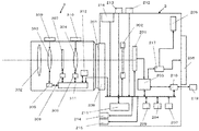
図1は、本実施の形態に係るデジタルカメラの斜視図である。図2は、本実施の形態に係るデジタルカメラの構成図である。
1. Configuration 1-1. Overview of Overall Configuration FIG. 1 is a perspective view of a digital camera according to the present embodiment. FIG. 2 is a configuration diagram of the digital camera according to the present embodiment.
本実施の形態のデジタルカメラ1は、カメラ本体2と、カメラ本体2に着脱可能な交換レンズ3とを備える。
The digital camera 1 according to the present embodiment includes a
カメラ本体2は、CMOSセンサ201、シャッタ202、信号処理プロセッサ203(DSP)、バッファメモリ204、液晶モニタ205、電子ビューファインダー206(EVF)、電源207、ボディマウント208、フラッシュメモリ209、カードスロット210、CPU211、シャッタスイッチ212、ストロボ213、マイク214、スピーカー215及びモードダイヤル216を備える。
The
交換レンズ3は、レンズマウント301、ズームレンズ303やフォーカスレンズ304を含むレンズ系、ズームレンズ303を駆動させるズーム駆動部305、フォーカスレンズ304を駆動させるフォーカス駆動部306、絞り307、絞り307を駆動させる絞り駆動部308、ズームリング309、フォーカスリング310、レンズコントローラ311及びフラッシュメモリ312を備える。以下、構成を具体的に説明する。
The
1−2.カメラ本体の構成
カメラ本体2は、交換レンズ3のレンズ系によって集光された被写体像を撮像して、画像データとして記録できるように構成されている。
1-2. Configuration of Camera Body The
CMOSセンサ201は、受光素子と、AGC(ゲイン・コントロール・アンプ)と、ADコンバータとを含んで構成される。受光素子は、レンズ系によって集光された光学的信号を電気信号に変換し、画像データを生成する。AGCは、受光素子から出力された電気信号を増幅する。ADコンバータは、AGCから出力された電気信号をデジタル信号に変換する。なお、CMOSセンサ201は、CPU211から受信した制御信号に従って、露光、転送、電子シャッタなどの各種の動作を行う。この各種動作は、タイミングジェネレータ等で実現可能である。電子シャッタは、受光素子における1フレーム当たりの受光時間(撮像時間)を調整する。
The
メカシャッタ202は、レンズ系を介して入射された、CMOSセンサ201に対する光学的信号の遮断又は通過を切り替える。メカシャッタ202は、メカシャッタ202の駆動部によって駆動される。メカシャッタ202の駆動部は、モータ、バネ等の機構部品で実現され、CPU211の制御に基づきメカシャッタ202を駆動する。要するに、メカシャッタ202は開けたり閉じたりして、CMOSセンサ201に当たる光の量を時間的に調整する。
The
信号処理プロセッサ203(DSP)は、ADコンバータによってデジタル信号に変換された画像データに、所定の画像処理を施す。所定の画像処理としては、ガンマ変換、YC変換、電子ズーム処理、圧縮処理、伸張処理等が考えられるが、これに限られるものではない。 The signal processor 203 (DSP) performs predetermined image processing on the image data converted into a digital signal by the AD converter. Examples of the predetermined image processing include gamma conversion, YC conversion, electronic zoom processing, compression processing, and expansion processing, but are not limited thereto.
バッファメモリ204は、信号処理プロセッサ203で処理を行う際、および、CPU211で制御処理を行う際に、ワークメモリとして機能する。バッファメモリ204は、例えば、DRAMなどで実現可能である。
The
液晶モニタ205は、カメラ本体2の背面に配置され、CMOSセンサ201で生成された画像データまたはその画像データに所定の処理が施された画像データを表示可能である。ここで液晶モニタ205に入力される画像信号は、信号処理プロセッサ203から液晶モニタ205に出力される際、DAコンバータによってデジタル信号からアナログ信号に変換される。
The
電子ビューファインダー206は、カメラ本体2に配置され、CMOSセンサ201で生成された画像データまたはその画像データに所定の処理が施された画像データを表示可能である。電子ビューファインダー206に入力される画像信号も同様に、信号処理プロセッサ203から電子ビューファインダー206に出力される際、DAコンバータによってデジタル信号からアナログ信号に変換される。
The
ここで液晶モニタ205と電子ビューファインダー206の表示は、表示切替手段217によって切り替えられる。すなわち、液晶モニタ205に画像が表示されている間は、電子ビューファインダー206には何も表示されない。また、電子ビューファインダー206に画像が表示されている間は、液晶モニタ205には何も表示されない。表示切替手段217は、例えば、切り替えスイッチなどの物理的な構造で実現することができる。例えば、信号処理プロセッサ203と液晶モニタ205が電気的に接続されている場合、切り替えスイッチが切り替えられることによって、信号処理プロセッサ203と液晶モニタ205間の電気的接続が切断され、信号処理プロセッサ203と電子ビューファインダー206とが電気的に接続される。なお、上記の方法に限られず、表示切替手段217は、CPU211などからの制御信号に基づいて、液晶モニタ205と電子ビューファインダー206の表示の切り替えを行なってもよい。
Here, the display on the
以上のように、液晶モニタへの表示と、電気ビューファインダーへの表示とを切り替えるようにしている。但し、これは、構成上の制限からくる問題であるため、液晶モニタへの表示と、電子ビューファインダーへの表示を同時に行なうようにしてもかまわない。ここで、同時に表示する場合、液晶モニタに表示する画像と、電子ビューファンダーへ表示する画像は、同じ画像であっても、違う画像であってもかまわない。 As described above, the display on the liquid crystal monitor and the display on the electric viewfinder are switched. However, since this is a problem due to structural limitations, the display on the liquid crystal monitor and the display on the electronic viewfinder may be performed simultaneously. Here, when displaying simultaneously, the image displayed on the liquid crystal monitor and the image displayed on the electronic view funder may be the same image or different images.
電源207は、デジタルカメラ1で消費するための電力を供給する。電源207は、例えば乾電池であってもよいし、充電池であってもよい。また、電源コードにより外部から供給される電力をデジタルカメラ1に供給するものであってもよい。
The
ボディマウント208は、交換レンズ3のレンズマウント301と相俟って、交換レンズ3の着脱を可能にする部材である。ボディマウント208は、交換レンズ3と接続端子等を用い電気的に接続可能であるとともに、係止部材等のメカニカルな部材によって機械的にも接続可能である。ボディマウント208は、交換レンズ3に含まれるレンズコントローラ311からの信号をCPU211へ出力できるとともに、CPU211からの信号を交換レンズ3のレンズコントローラ311に出力できる。すなわち、CPU211は、交換レンズ3側のレンズコントローラ311と制御信号やレンズ系に関する情報などを送受信可能である。
The
フラッシュメモリ209は、内蔵メモリとして用いられる記憶媒体である。フラッシュメモリ209は、画像データまたはその画像データに所定の処理が施された画像データを記憶可能である。また、デジタル化された音声信号も記憶可能である。加えて、画像データや音声信号の他にCPU211の制御のためのプログラムや設定値などを記憶可能である。
The
ここで本実施の形態のフラッシュメモリ209は、カメラ本体2に装着された交換レンズの種別を判断するための種別IDのリストを格納している。このリストは、動画対応の交換レンズに対する種別IDを含む。カメラ本体2は、交換レンズ3から取得した種別IDを参照することで、装着された交換レンズが動画対応レンズであるか否かを判別することができる。
Here, the
カードスロット210は、記憶媒体であるメモリカード218を着脱するためのスロットである。メモリカード218は、画像データもしくはその画像データに所定の処理が施された画像データまたはデジタル化された音声信号も記憶可能である。
The
CPU211はカメラ本体2の動作を制御する。CPU211は、マイクロコンピュータで実現してもよく、ハードワイヤードな回路で実現してもよい。すなわち、CPU211は、各種の制御を実行する。また、CPU211は、レンズコントローラ311との間で制御信号のやり取りを行なうことも可能である。例えば、CPU211は、レンズコントローラ311に対して、絞りを制御するための制御信号(例えば、F値又はAV値)、及び、絞りの駆動速度(絞り値の変化速度)を示す制御信号を送信可能である。
The CPU 211 controls the operation of the
シャッタスイッチ212は、カメラ本体2の上面に設けられた釦であり、使用者からの半押しおよび全押し操作を検知する操作手段である。シャッタスイッチ212は、使用者から半押し操作を受け付けると、半押し信号をCPU211に出力する。一方、シャッタスイッチ212は、使用者から全押し操作を受け付けると、全押し信号をCPU211に出力する。これらの信号に基づいて、CPU211は様々な制御を行なう。
The
モードダイヤル216は、使用者の操作に応じて、複数のモードから一つのモードを選択する。複数のモードは、動画撮影モード、静止画撮影モード及び再生モードを含む。モードダイヤル216は、使用者の操作に応じて、一つのモードが選択されると、選択されたモードに対応する情報をCPU211に送信する。CPU211は、受信した情報に基づき、カメラ本体2の各部を制御する。CPU211は、交換レンズ3にも制御信号を送信して、レンズコントローラ311に交換レンズ3の各部を制御させる。また、カメラ本体2の外装には使用者が動画の撮影を指示するための動画撮影ボタン219が設けられている。
The
以下、動画撮影モードについて説明する。動画撮影モードは複数のサブモードを有する。複数のサブモードには、「動画Pモード」、「動画Aモード」、「動画Sモード」及び「動画Mモード」がある。使用者は、モードの設定を、CPU211によって液晶モニタ205に表示された選択画面を用いて設定することが可能である。図3に、液晶モニタ205に表示されるサブモードの選択画面の一例を示す。以下、各サブモードについて説明する。
Hereinafter, the moving image shooting mode will be described. The moving image shooting mode has a plurality of sub modes. The plurality of sub modes include “moving image P mode”, “moving image A mode”, “moving image S mode”, and “moving image M mode”. The user can set the mode using the selection screen displayed on the liquid crystal monitor 205 by the CPU 211. FIG. 3 shows an example of a sub-mode selection screen displayed on the
「動画Pモード」:動画撮影中に露出制御をするため、絞り値、露光時間、及び、感度(AGCの感度)が自動調整されるモードである。
「動画Aモード」:動画撮影中に露出制御をするため、絞り値を固定した状態で、露光時間、及び、感度が自動調整されるモードである。
「動画Sモード」:動画撮影中に露出制御をするため、露光時間を固定した状態で、絞り値、及び、感度が自動調整されるモードである。自動調整とは、CPU211により各部が自動的に調整されることを意味する。
「動画Mモード」:動画撮影中に露出制御をするため、絞り値、露光時間、及び、感度が、使用者の指示(操作)に応じて(手動により)調整されるモードである。
なお、上記各モードにおける感度は、使用者設定で自動調整するか、固定するかを選択可能である。
“Movie P mode”: A mode in which the aperture value, exposure time, and sensitivity (sensitivity of AGC) are automatically adjusted in order to control exposure during movie shooting.
“Movie A mode”: a mode in which exposure time and sensitivity are automatically adjusted in a state where the aperture value is fixed in order to control exposure during movie shooting.
“Movie S mode”: A mode in which the aperture value and the sensitivity are automatically adjusted in a state where the exposure time is fixed in order to perform exposure control during movie shooting. The automatic adjustment means that each part is automatically adjusted by the CPU 211.
“Moving image M mode”: A mode in which the aperture value, exposure time, and sensitivity are adjusted (manually) according to a user's instruction (operation) in order to control exposure during moving image shooting.
It should be noted that the sensitivity in each of the above modes can be selected to be automatically adjusted by the user setting or fixed.
1−3.交換レンズの構成
レンズ系は、ズームレンズ303とフォーカスレンズ304と対物レンズ302を含んで構成され、被写体からの光を集光する。ズームレンズ303は、ズーム駆動部305又はズームリング309によって駆動され、ズーム倍率を調整するものである。フォーカスレンズ304は、フォーカス駆動部306又はフォーカスリング310によって駆動され、ピントの調節を行なう。フォーカスレンズ304やズームレンズ303は可動レンズである。
1-3. Configuration of Interchangeable Lens The lens system includes a
ズーム駆動部305は、レンズコントローラ311の制御にしたがってズームレンズ303を駆動する。フォーカス駆動部306は、レンズコントローラ311の制御にしたがって、フォーカスレンズ304を駆動する。
The
絞り307は、レンズ系を通過する光の量を調整する。例えば、光の調整は、5枚羽根などで構成される開口径を大きくしたり、小さくしたりすることで可能である。 The diaphragm 307 adjusts the amount of light passing through the lens system. For example, the light can be adjusted by increasing or decreasing the opening diameter formed by five blades.
絞り駆動部308は、絞り307の開口径の大きさを変更するものである。また、絞り駆動部308は、レンズコントローラ311からの制御信号に含まれる駆動速度に応じて、絞り307を制御可能である。
The
実施の形態1において、絞り駆動部308は、レンズコントローラ311の制御に基づいて、絞り307の開口径の大きさを変更する。ここで開口径の大きさは、絞り値(F値)および絞り値テーブルに基づいて指定可能である。本実施の形態では、絞り駆動部308は、レンズコントローラ311からの制御に基づいて絞り307を駆動するようにしている。しかし、この駆動方法に限らず、機械的な方法によって絞り307を駆動させてもよい。この場合、ボディマウント208に連動ピンを設け、この連動ピンの駆動を絞り駆動部308が受けて、絞り307を駆動させることで可能となる。連動ピンは、CPU211により制御されたモータなどで駆動される。
In the first embodiment, the
ズームリング309は、交換レンズ3の外装に設けられ、使用者からの操作に応じて、ズームレンズ303を駆動させるものである。また、フォーカスリング310は、交換レンズ3の外装に設けられ、使用者からの操作に応じて、フォーカスレンズ304を駆動させるものである。
The
レンズコントローラ311は、交換レンズ3全体を制御する。レンズコントローラ311は、マイクロコンピュータで実現してもよく、ハードワイヤードな回路で実現してもよい。すなわち、レンズコントローラ311は、各種の制御を実行する。
The
例えば、レンズコントローラ311は、絞りの制御信号(絞り値及び駆動速度)を取得した場合、絞り値及び駆動速度に基づいて、絞り駆動部308を制御する。絞り駆動部308は、この制御によって絞り307を駆動する。
For example, when the
フラッシュメモリ312は内蔵メモリとして用いられる記憶媒体である。フラッシュメモリ312には、交換レンズ3の種別を示す種別IDが格納されている。この種別IDは、レンズコントローラ311によってカメラ本体2のCPU211に送信される。
The
フラッシュメモリ312は、絞りの駆動速度に関して、駆動可能な範囲の最大速度と最低速度の情報を格納している。この駆動速度の最大値と最小値についても、レンズコントローラ311によってCPU211に送信可能である。
The
レンズコントローラ311は、交換レンズ3がカメラ本体2に装着されたことを検知すると、CPU211に絞りの駆動速度の情報を送信する。また、交換レンズ3がカメラ本体2に装着されると、カメラ本体2からレンズコントローラ311に電力が供給される。このため、レンズコントローラ311は、電力が供給されたことを検知して、絞りの駆動速度の情報を送信できる。
When the
2.動作
デジタルカメラ1の動作の一例を説明する。以下、カメラ本体2に交換レンズ3が装着されていない状態から、交換レンズ3が装着されたときの、カメラ本体2の動作説明を行なう。なお、以下では、感度は自動調整可能な場合を説明するが、感度は固定でもよい。
2. Operation An example of the operation of the digital camera 1 will be described. Hereinafter, the operation of the
2−1.レンズ装着時の動作
図4を参照し、カメラ本体2に交換レンズ3が装着されたときのカメラ本体2(CPU211)の動作を説明する。レンズコントローラ311は、交換レンズ3がカメラ本体2に装着されたことを検知すると、駆動速度の情報をCPU211に送信する。CPU211は、カメラ本体2に交換レンズ3が装着されると、レンズコントローラ311から駆動速度(最大値及び最小値)を取得したか否かを判別する(A1)。CPU211は、駆動速度の情報を取得すると、フラッシュメモリ209に格納する(A2)。
2-1. Operation when Lens is Mounted Referring to FIG. 4, the operation of the camera body 2 (CPU 211) when the
2−2.動画撮影時の露出制御
動画撮影時の露出制御動作を説明する。カメラ本体2が動画モードに設定された状態で、動画撮影ボタン219が押下されると、カメラ本体2のCPU211は動画撮影を開始する。そして、CPU211は、動画撮影が開始された後、動画撮影ボタン219が再度押下されると、動画撮影を終了する。以下、この動作を、図5を参照して具体的に説明する。
2-2. Exposure control during movie shooting An exposure control operation during movie shooting will be described. When the moving image shooting button 219 is pressed while the
動画撮影ボタン219が押下されると、CPU211は、現在の動画モードのサブモードが「動画Pモード」又は「動画Aモード」に該当するか否かを判別する(B1)。サブモードが「動画Pモード」又は「動画Aモード」である場合、CPU211は絞りの駆動速度をY2に設定する(B2)。この駆動速度Y2はバッファメモリ204に格納される。駆動速度Y2は、特に限定されないが、後述する駆動速度Y1よりも速い速度に設定する。なお、本実施の形態では、CPU211は、レンズコントローラ311から取得した絞りの駆動速度の最大値および最小値を記憶しており、駆動速度Y2は駆動速度の最小値から最大値の間の値であればよい。
When the moving image shooting button 219 is pressed, the CPU 211 determines whether or not the sub mode of the current moving image mode corresponds to “moving image P mode” or “moving image A mode” (B1). When the sub mode is “moving image P mode” or “moving image A mode”, the CPU 211 sets the aperture driving speed to Y2 (B2). The driving speed Y2 is stored in the
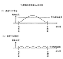
ここで、図6A、図6Bを参照して、絞りの駆動について説明する。本実施形態において絞りの駆動速度とは、絞りの駆動開始から絞りの目標値に達するまでの平均の駆動速度である。より遅い駆動速度Y1で絞りを駆動した場合、より速い駆動速度Y2で絞りを駆動した場合よりも、絞りの駆動開始から絞りの目標値に達するまでの時間がかかる。このため、絞りがより緩やかに変化するため、画質の急激な変化を防止できる。 Here, the driving of the diaphragm will be described with reference to FIGS. 6A and 6B. In the present embodiment, the aperture driving speed is an average driving speed from the start of aperture driving until the target aperture value is reached. When the diaphragm is driven at a slower drive speed Y1, it takes more time to start reaching the target value of the diaphragm after starting the diaphragm drive than when the diaphragm is driven at a faster drive speed Y2. For this reason, since the aperture changes more slowly, it is possible to prevent an abrupt change in image quality.
絞りの駆動速度の調整は、例えば、以下の方法が考えられる。
「1」目標の絞り値まで変化させる際の絞り駆動の制御回数を調整する(図6A参照)。
「2」目標の絞り値まで変化させる際の駆動速度自体を調整する(図6B参照)。
For example, the following methods can be considered for adjusting the driving speed of the diaphragm.
“1” Adjust the number of times of aperture drive control when changing to the target aperture value (see FIG. 6A).
“2” The drive speed itself when changing to the target aperture value is adjusted (see FIG. 6B).
上記「1」の場合、1回の制御に要する時間は同じであるため、制御回数を変更することで絞りの駆動速度を調整できる。例えば、より速い駆動速度Y2での制御の場合は、図6A(a)に示すように、1回の制御により絞りを目標の絞り値に達するよう制御する。これに対して、より遅い駆動速度Y1での制御の場合は、図6A(b)に示すように、5回の制御により絞りを目標の絞り値に達するよう制御している。このように制御回数を増やして目標の絞り値まで変化させる時間がよりかかるようにすることで、より遅い駆動速度Y1を実現できる。つまり、カメラ本体2は、交換レンズ3に対して、駆動速度Y2の場合、目標絞り値に対して1回の制御信号により絞りを駆動する一方、駆動速度Y1の場合、目標絞り値に対して5回の制御信号により絞りを駆動する。このようにすれば、図6Aのように、絞りが目標値に達するまでの、絞りの平均駆動速度を制御できるようになる。
In the case of “1”, since the time required for one control is the same, the driving speed of the diaphragm can be adjusted by changing the number of times of control. For example, in the case of control at a higher drive speed Y2, as shown in FIG. 6A (a), the aperture is controlled to reach the target aperture value by a single control. On the other hand, in the case of control at a slower driving speed Y1, as shown in FIG. 6A (b), the aperture is controlled to reach the target aperture value by performing the control five times. Thus, by increasing the number of times of control and taking more time to change to the target aperture value, a slower driving speed Y1 can be realized. That is, the
上記「2」の場合、異なる駆動速度は次のようにして実現する。カメラ本体2は、交換レンズ3に対して、Y1またはY2のいずれかに設定された駆動速度を指定する。これによって、図6Bのように、絞りの駆動速度を制御する。上記「1」、「2」のいずれの方法の場合も、駆動速度Y1で駆動した場合よりも駆動速度Y2で駆動した場合の方が結果として絞りを目標値に早く到達させることができる。
In the case of “2”, different driving speeds are realized as follows. The
なお、カメラ本体2は露出制御の目標範囲(適正露出の範囲)を有している。CPU211は、CMOSセンサ201で得られた画像データの輝度を検知する。CPU211は動画モードに応じて、その検知した輝度に基づき、CMOSセンサ201に対する露出が適正露出となるように、すなわち、露出制御の目標範囲内に収まるように、絞り、露光時間、感度等を自動制御する。ここで、「動画Sモード」における露出の目標範囲の幅を、「動画Pモード」や「動画Aモード」における露出の目標範囲の幅よりも広くしてもよい。これにより、「動画Sモード」において絞りを速やかに適正値に制御することが可能となる。つまり、目標露出付近でのハンチングを軽減する。ハンチングとは、例えば、デジタルカメラ1が絞りを自動調整する際、目標範囲に露出を収めることができず、露出状態が目標露出の前後(明るい側と暗い側)を行き来することをいう。
The
図5に戻り、次に、CPU211は、サブモードが「動画Pモード」であるか否かを判別する(B3)。「動画Pモード」である場合、CPU211は「動画Pモードの動作」に移行する(B4)。一方、「動画Pモード」でない場合すなわち「動画Aモード」である場合、CPU211は「動画Aモードの動作」に移行する(B5)。「動画Pモードの動作」及び「動画Aモードの動作」の詳細は後述する。 Returning to FIG. 5, next, the CPU 211 determines whether or not the sub mode is the “moving image P mode” (B3). In the case of “moving image P mode”, the CPU 211 shifts to “operation of moving image P mode” (B4). On the other hand, when it is not “moving image P mode”, that is, when it is “moving image A mode”, the CPU 211 shifts to “operation of moving image A mode” (B5). Details of the “moving image P mode operation” and “moving image A mode operation” will be described later.
一方、ステップB1において、サブモードが「動画Pモード」又は「動画Aモード」でない場合、CPU211は、絞りの駆動速度をY1に設定する(B6)。ここで、駆動速度Y1は駆動速度Y2よりも小さい値である。駆動速度Y1はバッファメモリ204に格納される。
On the other hand, if the sub mode is not “Movie P mode” or “Movie A mode” in step B1, the CPU 211 sets the aperture driving speed to Y1 (B6). Here, the driving speed Y1 is smaller than the driving speed Y2. The driving speed Y1 is stored in the
続いて、CPU211は、サブモードが「動画Sモード」であるか否かを判別する(B7)。「動画Sモード」である場合、CPU211は「動画Sモードの動作」に移行する(B8)。一方、「動画Sモード」でない場合すなわち「動画Mモード」の場合、CPU211は「動画Mモードの動作」に移行する(B9)。「動画Sモードの動作」及び「動画Mモードの動作」の詳細は後述する。 Subsequently, the CPU 211 determines whether or not the sub mode is the “moving image S mode” (B7). In the case of “moving image S mode”, the CPU 211 shifts to “operation of moving image S mode” (B8). On the other hand, when it is not “moving image S mode”, that is, when it is “moving image M mode”, the CPU 211 shifts to “operation of moving image M mode” (B9). Details of the “moving image S mode operation” and “moving image M mode operation” will be described later.
以上のように、「動画Sモード」や「動画Mモード」のように、露出制御のため、絞りを単体で制御する可能性があるモードについては、絞りの駆動速度(Y1)を、他のモード(「動画Pモード」や「動画Aモード」)の駆動速度(Y2)よりも遅くなるようにした。これによって、絞りを単体で動かすことによる、露出状態の変化を滑らかにして対応することができる。一方で、「動画Pモード」のように、絞りを調整した際、絞り以外のパラメータで露出状態を徐々に変化させることができるので、「動画Sモード」等よりも絞りの駆動速度を高速にできる。これによって、本実施の形態によれば、「動画Pモード」の場合、目標となる露出状態(明るさ)に短時間で制御できる。 As described above, the aperture drive speed (Y1) is set to other modes for modes in which the aperture may be controlled independently for exposure control, such as “Movie S mode” and “Movie M mode”. The driving speed (Y2) of the mode (“moving image P mode” or “moving image A mode”) is made slower. Thereby, it is possible to cope with a smooth change in the exposure state caused by moving the diaphragm alone. On the other hand, when the aperture is adjusted as in “Movie P mode”, the exposure state can be gradually changed with parameters other than the aperture, so the drive speed of the aperture is faster than “Movie S mode” or the like. it can. As a result, according to the present embodiment, in the “moving image P mode”, the target exposure state (brightness) can be controlled in a short time.
2−3.各動画モードの露出制御動作
以下、各動画モードの露出制御動作について説明する。
2-3. Exposure Control Operation in Each Movie Mode Hereinafter, the exposure control operation in each movie mode will be described.
2−3−1.動画Pモードの露出制御動作
図7を参照して「動画Pモード」における露出制御動作を説明する。
まず、CPU211は、カメラ本体2に装着された交換レンズ3が動画対応レンズか否かを判別する(C1)。例えば、CPU211は、フラッシュメモリ209に記憶された、レンズコントローラ311から取得した種別IDと、フラッシュメモリ209に格納されている種別IDとを比較し、一致する場合、動画対応レンズであると判断する。
2-3-1. Exposure Control Operation in Movie P Mode The exposure control operation in “Movie P mode” will be described with reference to FIG.
First, the CPU 211 determines whether or not the
CPU211は、動画対応レンズであると判断した場合、露出状態が所定値(例えば、1EV)以上変化したか否かを判別する(C2)。前述のようにCPU211は、CMOSセンサ201で得られる画像データの輝度を監視しており、監視した画像データの輝度が、前回の露出制御を行なった時点の画像データの輝度から所定値以上変化したか否かを判別している。ここで画像データの輝度は、例えば、画像全体の輝度の平均をとってもよいし、画像の一部の平均をとってもよい。また、画像を複数の領域に分割し、各領域に重み付けをした状態で、重み付けした各領域の輝度の平均値をとってもよい。これらの方法は、一般的に用いられている測光の方法であるため、詳しい説明は省略する。
If the CPU 211 determines that the lens is a movie-compatible lens, the CPU 211 determines whether the exposure state has changed by a predetermined value (for example, 1 EV) or more (C2). As described above, the CPU 211 monitors the brightness of the image data obtained by the
ステップC2において露出状態が所定値以上変化した場合、CPU211は、適正露出になるように(すなわち、露出がその目標範囲に収まるように)、絞り、露光時間及び/又は感度を制御する(C3)。CPU211は、絞りを制御する場合、絞りの駆動速度としてバッファメモリ204から読み出した値「Y2」をレンズコントローラ311に送信する。ここで、CPU211は、絞りを制御する場合、同時に露光時間を制御するとよい。例えば、絞りを開放側に稼動した場合、露光時間を短くして、露出状態が動画像のフレーム単位で徐々に変化するようにするとよい。このようにすれば、絞りの分解能が低いことによる、露出状態の変化が大きくなってしまうことを軽減できる。
When the exposure state changes in step C2 by a predetermined value or more, the CPU 211 controls the aperture, exposure time, and / or sensitivity so that the proper exposure is obtained (that is, the exposure is within the target range) (C3). . When controlling the aperture, the CPU 211 transmits the value “Y2” read from the
一方、ステップC1において動画対応レンズでないと判断された場合、CPU211は、ステップC2と同様に、露出状態が所定値以上変化したか否かを判別する(C4)。 On the other hand, if it is determined in step C1 that the lens is not a movie-compatible lens, the CPU 211 determines whether or not the exposure state has changed by a predetermined value or more as in step C2 (C4).
ステップC4において露出状態が所定値以上変化した場合、CPU211は、適正露出になるように、絞りよりも、露光時間及び/又は感度を優先して制御する(C5)。例えば、CPU211は絞りを動かさないようにする。又は、CPU211は、プログラム線図において、絞りの動作ポイントが減るように制御する。このようにすれば、動画非対応の交換レンズがカメラ本体に装着された場合において、絞りを制御したことにより映像として好ましくない動画像が生成されることを防止できる。 When the exposure state changes by a predetermined value or more in step C4, the CPU 211 controls the exposure time and / or sensitivity with priority over the aperture so as to achieve proper exposure (C5). For example, the CPU 211 does not move the aperture. Alternatively, the CPU 211 performs control so that the operating point of the aperture is reduced in the program diagram. In this way, when an interchangeable lens that does not support moving images is attached to the camera body, it is possible to prevent an undesirable moving image from being generated as a video due to the control of the aperture.
2−3−2.動画Aモードの露出制御動作
図8を参照して「動画Aモード」における露出制御動作を説明する。
CPU211は、ステップC2と同様に、露出状態が所定値(例えば、1EV)以上変化したか否かを判別する(D1)。
2-3-2. Exposure Control Operation in Movie A Mode The exposure control operation in “Movie A mode” will be described with reference to FIG.
As in step C2, the CPU 211 determines whether or not the exposure state has changed by a predetermined value (for example, 1 EV) or more (D1).
ステップD1において露出状態が所定値以上変化した場合、CPU211は、適正露出になるように、露光時間及び/又は感度を制御する(D2)。 When the exposure state changes in step D1 by a predetermined value or more, the CPU 211 controls the exposure time and / or sensitivity so as to achieve proper exposure (D2).
この制御により、「動画Aモード」では、動画撮影時において、絞りを固定した状態で露光時間を自動制御できるため、被写界深度を固定した状態で露出状態を保つことができる。 With this control, in the “moving image A mode”, since the exposure time can be automatically controlled with the aperture fixed at the time of moving image shooting, the exposure state can be maintained with the fixed depth of field.
2−3−3.動画Sモードの露出制御動作
図9を参照して「動画Sモード」における露出制御動作を説明する。
CPU211は、露出状態が所定値(例えば、1EV)以上変化したか否かを判別する(E1)。
2-3-3. Exposure Control Operation in Movie S Mode An exposure control operation in “Movie S mode” will be described with reference to FIG.
The CPU 211 determines whether or not the exposure state has changed by a predetermined value (for example, 1 EV) or more (E1).
ステップE1において露出状態が所定値以上変化した場合、CPU211は、適正露出になるように、絞り及び/又は感度を制御する(E2)。CPU211は、絞りを制御する場合、絞りの駆動速度としてバッファメモリ204から読み出した値「Y1」をレンズコントローラ311に送信する。
When the exposure state changes in step E1 by a predetermined value or more, the CPU 211 controls the aperture and / or sensitivity so that the appropriate exposure is obtained (E2). When controlling the aperture, the CPU 211 transmits the value “Y1” read from the
これにより、「動画Sモード」では動画撮影時において、露光時間を固定した状態で、絞りを自動制御できる。 Thereby, in the “moving image S mode”, the aperture can be automatically controlled with the exposure time fixed at the time of moving image shooting.
2−3−4.動画Mモードの露出制御動作
動画Mモードにおいて、CPU211は、使用者が設定した絞り、露光時間又は感度に応じて、各パラメータを制御する。ここでCPU211は、絞りを制御する場合、絞りの駆動速度としてバッファメモリ204から読み出した値「Y1」をレンズコントローラ311に送信する。
2-3-4. Exposure Control Operation in Movie M Mode In the movie M mode, the CPU 211 controls each parameter according to the aperture, exposure time, or sensitivity set by the user. Here, when controlling the aperture, the CPU 211 transmits the value “Y1” read from the
CPU211は、絞りを制御する場合、図10に示すような制御を行ってもよい。まず、CPU211は、ステップC1と同様に、カメラ本体2に装着された交換レンズ3が動画対応レンズか否かを判断する(F1)。
When controlling the diaphragm, the CPU 211 may perform control as shown in FIG. First, as in step C1, the CPU 211 determines whether or not the
CPU211は、カメラ本体2に装着された交換レンズ3が動画対応レンズであると判断した場合、使用者操作による絞り値の変更を検知する(F2)。例えば、CPU211は、外装に設けられた操作部材が操作されると、絞り値の変更を検知できる。
When the CPU 211 determines that the
CPU211は、ステップF2において絞り値の変更を検知した場合、絞りを制御する(F3)。なお、CPU211は、絞りを制御する場合、絞りの駆動速度としてバッファメモリ204から読み出した値「Y1」をレンズコントローラ311に送信する。
When the CPU 211 detects a change in the aperture value in step F2, the CPU 211 controls the aperture (F3). When controlling the aperture, the CPU 211 transmits the value “Y1” read from the
一方、CPU211は、ステップF1において、カメラ本体2に装着された交換レンズ3が動画対応レンズでないと判断された場合、CPU211は、ステップF2と同様に、使用者操作による絞り値の変更を検知する(F4)。
On the other hand, if the CPU 211 determines in step F1 that the
ステップF4において絞り値の変更を検知した場合、CPU211は、使用者操作により設定された絞り値にしたがい絞りを制御すると共に、警告画面を表示させる(F5)。警告画面には、例えば、絞り値を変更することによって、動画像が乱れるなど、動画像に悪影響があることを知らせる報知画像が考えられる。このようにすれば、使用者は、交換レンズが動画非対応であることによって映像が乱れる可能性があることを認識することができる。なお、CPU211は、絞りを制御する場合、絞りの駆動速度としてバッファメモリ204から読み出した値「Y1」をレンズコントローラ311に送信する。
When the change of the aperture value is detected in step F4, the CPU 211 controls the aperture according to the aperture value set by the user operation and displays a warning screen (F5). The warning screen may be a notification image that informs that there is an adverse effect on the moving image, for example, the moving image is disturbed by changing the aperture value. In this way, the user can recognize that there is a possibility that the image is disturbed when the interchangeable lens is not compatible with moving images. When controlling the aperture, the CPU 211 transmits the value “Y1” read from the
3.用語の対応
CMOSセンサ201は撮像手段の一例である。CPU211は、検知手段、送信手段、設定手段、制御手段の一例である。動画Pモードは、第1のモードの一例である。動画Sモードは第2モードの一例である。CPU211により液晶モニタ205に表示された選択画面はモード設定手段の一例である。
3. Correspondence of Terms The
4.まとめ
本実施の形態において、交換レンズ3が装着可能なカメラ本体2は、交換レンズ3を介して入射した光を撮像し、画像データを生成するCMOSセンサ201と、交換レンズ2を介して入射した光の光量を検知するCPU211を備える。CPU211は、交換レンズ3の絞り307の絞り値及び絞りの駆動速度と、絞り307以外の露出に関する設定である露出条件とを設定し、設定された絞り値及び絞りの駆動速度を制御するための制御信号を交換レンズに送信する。また、CPU211により液晶モニタ205に表示された選択画面は、複数の動作モードから1つの動作モードを選択する。複数の動作モードは、動画像撮像中にCPU211で検知された光量に応じて絞り307及び露出条件を自動調整する第1モードと、動画像撮像中にCPU211で検知された光量に応じて、露出条件を固定した状態で絞り307を自動調整する第2モードとを含む。第2モードで自動調整する際の絞り307の駆動速度は、第1モードで自動調整する際の絞りの駆動速度よりも遅い。
4). Summary In the present embodiment, the
この構成により、カメラ本体2は、露光の急激な変化を防止し、適正な露出制御が可能となり、使用者にとって好ましい動画像を撮影できる。なお、絞りの駆動速度を遅くすると、絞りが駆動されることにより変化する光量の変化速度が遅くなる。一方で、絞りの駆動速度を速くすると、絞りが駆動されることにより変化する光量の変化速度が速くなる。このため、カメラ本体2は、露光の急激な変化を防止できる。
With this configuration, the
上記の例では、レンズ交換が可能なカメラ本体を備えた撮像装置について説明したが、コンパクトカメラのようなレンズとボディが一体となった撮像装置に対しても本実施形態の思想を適用することは可能である。 In the above example, the imaging apparatus having a camera body capable of exchanging lenses has been described. However, the idea of the present embodiment is also applied to an imaging apparatus in which a lens and a body are integrated, such as a compact camera. Is possible.
5.他の実施の形態
本発明の実施の形態として、実施の形態1を例示した。しかし、本発明はこれには限らない。すなわち、本発明は、上記実施の形態1に限られず、適宜修正された実施の形態に対しても適用可能である。
5. Other Embodiments Embodiment 1 has been illustrated as an embodiment of the present invention. However, the present invention is not limited to this. That is, the present invention is not limited to the first embodiment, and can be applied to embodiments that are appropriately modified.
実施の形態1では、動画像撮影(撮像+記録)時において、「動画Sモード」の絞りの駆動速度を、「動画Pモード」の絞りの駆動速度よりも遅くなるように制御した。すなわち、スルー画像が表示された状態で動画が記録されていないときは、上記制御を行っていない。動画撮影時にのみ上記制御を行うようにすれば、動画像撮影前において絞りの駆動速度を常時速い速度に固定でき、高速な絞り制御が実現できるので、動画像撮影開始前の適正露出に変化するまでの時間を短くできる。そのため、動画像撮影開始時において、露出をより適切に制御できるようになる。しかし、動画像撮影(撮像+記録)時のみならず、動画像撮像時全般において上記制御をするようにしてもかまわない。つまり、デジタルカメラ1がスルー画像(CMOSセンサで撮像した画像データ)を液晶モニタに表示した状態で動画が記録されていない場合においても上記制御をするようにしてもかまわない。 In the first embodiment, during moving image shooting (imaging + recording), the drive speed of the diaphragm in the “moving image S mode” is controlled to be slower than the drive speed of the diaphragm in the “moving image P mode”. That is, when no moving image is recorded in a state where a through image is displayed, the above control is not performed. If the above control is performed only during moving image shooting, the aperture drive speed can always be fixed at a high speed before moving image shooting, and high-speed aperture control can be realized. Can be shortened. Therefore, exposure can be controlled more appropriately at the start of moving image shooting. However, the above control may be performed not only during moving image shooting (imaging + recording) but also during moving image shooting in general. That is, the above control may be performed even when a moving image is not recorded in a state where the digital camera 1 displays a through image (image data captured by a CMOS sensor) on a liquid crystal monitor.
本実施の形態1では、露出状態が所定値(例えば、1EV)以上変化した場合に露出制御を行なうようにした。しかし、これに限られず、動画モードに応じた値(1/3EV〜2/3EV)以上に露出状態が変化した場合に露出制御を行なうようにしてもよい。 In the first embodiment, exposure control is performed when the exposure state changes by a predetermined value (for example, 1 EV) or more. However, the present invention is not limited to this, and exposure control may be performed when the exposure state changes to a value (1/3 EV to 2/3 EV) or more according to the moving image mode.
本発明は、露光を自動調整可能な撮像装置に適用可能である。例えば、交換レンズを装着可能なデジタルスチルカメラ、コンパクトカメラ、ムービ等に適用できる。 The present invention is applicable to an imaging apparatus capable of automatically adjusting exposure. For example, the present invention can be applied to a digital still camera, a compact camera, a movie or the like that can be attached with an interchangeable lens.
1 デジタルカメラ
2 カメラ本体
3 交換レンズ
201 CMOSセンサ
202 シャッタ
203 信号処理プロセッサ
204 バッファメモリ
207 電源
209 フラッシュメモリ
211 CPU
212 シャッタスイッチ
303 ズームレンズ
304 フォーカスレンズ
305 ズーム駆動部
306 フォーカス駆動部
307 絞り
308 絞り駆動部
311 レンズコントローラ
312 フラッシュメモリ
1
212
Claims (8)
前記交換レンズの絞りの絞り値と、前記絞りの駆動速度とを設定する制御手段と、
前記制御手段により設定された絞り値及び駆動速度に制御するための制御信号を前記交換レンズに送信する送信手段と、
自動的に露光を制御する複数の露出モードから1つの露出モードを設定する設定手段とを備え、
前記制御手段は、動画撮影時において、絞り値を前記設定された絞り値に変更する際に、前記設定された露出モードに応じて前記絞りの駆動制御の回数を調整し、
前記複数の露出モードは、動画像表示中に前記絞りのみを自動的に調整する第1モードと、前記第1モードとは異なる第2モードとを含み、
前記設定手段により前記第1モードが設定されたときに、前記制御手段は、前記第1モードが設定されたときの前記絞りの駆動制御の回数を、前記第2モードが設定されたときの前記絞りの駆動制御の回数よりも多くなるように、前記絞りの駆動制御の回数を調整する、
カメラ本体。 A camera body to which an interchangeable lens can be attached,
Control means for setting the aperture value of the aperture of the interchangeable lens and the driving speed of the aperture;
Transmitting means for transmitting a control signal for controlling the aperture value and driving speed set by the control means to the interchangeable lens;
Setting means for setting one exposure mode from a plurality of exposure modes for automatically controlling exposure,
The control means adjusts the number of times of driving control of the aperture according to the set exposure mode when changing the aperture value to the set aperture value during moving image shooting,
The plurality of exposure modes include a first mode that automatically adjusts only the aperture during moving image display, and a second mode that is different from the first mode,
When the first mode is set by the setting means, the control means indicates the number of times of driving control of the diaphragm when the first mode is set, and the number of times when the second mode is set. Adjusting the number of times of driving control of the diaphragm so as to be larger than the number of times of driving control of the diaphragm,
The camera body.
前記複数の露出モードの各々は、前記検知手段により検知された光量に応じて絞りを自動的に調整するモードである、
請求項1記載のカメラ本体。 It further comprises detection means for detecting the amount of light of the optical signal incident through the interchangeable lens,
Each of the plurality of exposure modes is a mode that automatically adjusts the aperture according to the amount of light detected by the detection means.
The camera body according to claim 1.
動画撮影時において前記撮像手段により生成された画像データを記録する記憶手段とをさらに備え、
前記制御手段は、前記絞り値を、前記設定された駆動速度で前記設定された絞り値に変更するときに、動画撮影時において前記記憶手段に記録される画像データの輝度の急激な変化を抑制するように前記絞りの駆動制御の回数を調整する、
請求項2記載のカメラ本体。 Imaging means for generating image data from an optical signal incident through the interchangeable lens;
Storage means for recording image data generated by the imaging means at the time of moving image shooting,
When the control means changes the aperture value to the set aperture value at the set drive speed, it suppresses a rapid change in the brightness of the image data recorded in the storage means during moving image shooting. Adjusting the number of times of driving control of the diaphragm so as to
The camera body according to claim 2.
前記撮像手段により生成された画像データを動画像のスルー画像として表示する表示手段とをさらに備え、
前記制御手段は、前記絞り値を、前記設定された駆動速度で前記設定された絞り値に変更するときに、前記表示手段にスルー画像として表示される画像データの輝度の急激な変化を抑制するように、前記絞りの駆動制御の回数を調整する、
請求項1記載のカメラ本体。 Imaging means for generating image data from an optical signal incident through the interchangeable lens;
Display means for displaying the image data generated by the imaging means as a through image of a moving image,
The control unit suppresses a rapid change in luminance of image data displayed as a through image on the display unit when the aperture value is changed to the set aperture value at the set driving speed. Adjusting the number of times of driving control of the aperture,
The camera body according to claim 1.
前記絞りを駆動する絞り駆動手段と、
前記絞りの絞り値と、前記絞りの駆動速度とを設定する制御手段と、
自動的に露光を制御する複数の露出モードから1つの露出モードを設定する設定手段とを備え、
前記制御手段は、動画撮影時において、絞り値を前記設定された絞り値に変更する際に、前記設定された露出モードに応じて前記絞りの駆動制御の回数を調整し、
前記複数の露出モードは、動画像表示中に前記絞りのみを自動的に調整する第1モードと、前記第1モードとは異なる第2モードとを含み、
前記設定手段により前記第1モードが設定されたときに、前記制御手段は、前記第1モードが設定されたときの前記絞りの駆動制御の回数を、前記第2モードが設定されたときの前記絞りの駆動制御の回数よりも多くなるように、前記絞りの駆動制御の回数を調整する、
撮像装置。 An optical system having an aperture;
Diaphragm driving means for driving the diaphragm;
Control means for setting a diaphragm value of the diaphragm and a driving speed of the diaphragm;
Setting means for setting one exposure mode from a plurality of exposure modes for automatically controlling exposure,
The control means adjusts the number of times of driving control of the aperture according to the set exposure mode when changing the aperture value to the set aperture value during moving image shooting,
The plurality of exposure modes include a first mode that automatically adjusts only the aperture during moving image display, and a second mode that is different from the first mode,
When the first mode is set by the setting means, the control means indicates the number of times of driving control of the diaphragm when the first mode is set, and the number of times when the second mode is set. Adjusting the number of times of driving control of the diaphragm so as to be larger than the number of times of driving control of the diaphragm,
Imaging device.
前記複数の露出モードの各々は、前記検知手段により検知された光量に応じて絞りを自動的に調整するモードである、
請求項5記載の撮像装置。 Further comprising detection means for detecting the amount of light of the optical signal incident through the optical system ;
Each of the plurality of exposure modes is a mode that automatically adjusts the aperture according to the amount of light detected by the detection means.
The imaging device according to claim 5.
動画撮影時において前記撮像手段により生成された画像データを記録する記憶手段とをさらに備え、
前記制御手段は、前記絞り値を、前記設定された駆動速度で前記設定された絞り値に変更するときに、動画撮影時において前記記憶手段に記録される画像データの輝度の急激な変化を抑制するように前記絞りの駆動制御の回数を調整する、
請求項6記載の撮像装置。 Imaging means for generating image data from an optical signal incident via the optical system ;
Storage means for recording image data generated by the imaging means at the time of moving image shooting,
When the control means changes the aperture value to the set aperture value at the set drive speed, it suppresses a rapid change in the brightness of the image data recorded in the storage means during moving image shooting. Adjusting the number of times of driving control of the diaphragm so as to
The imaging device according to claim 6.
前記撮像手段により生成された画像データを動画像のスルー画像として表示する表示手段とをさらに備え、
前記制御手段は、前記絞り値を、前記設定された駆動速度で前記設定された絞り値に変更するときに、前記表示手段にスルー画像として表示される画像データの輝度の急激な変化を抑制するように、前記絞りの駆動制御の回数を調整する、
請求項5記載の撮像装置。 Imaging means for generating image data from an optical signal incident via the optical system ;
Display means for displaying the image data generated by the imaging means as a through image of a moving image,
The control unit suppresses a rapid change in luminance of image data displayed as a through image on the display unit when the aperture value is changed to the set aperture value at the set driving speed. Adjusting the number of times of driving control of the aperture,
The imaging device according to claim 5.
Priority Applications (1)
| Application Number | Priority Date | Filing Date | Title |
|---|---|---|---|
| JP2014001451A JP5688552B2 (en) | 2009-02-27 | 2014-01-08 | Camera body and imaging device |
Applications Claiming Priority (3)
| Application Number | Priority Date | Filing Date | Title |
|---|---|---|---|
| JP2009045619 | 2009-02-27 | ||
| JP2009045619 | 2009-02-27 | ||
| JP2014001451A JP5688552B2 (en) | 2009-02-27 | 2014-01-08 | Camera body and imaging device |
Related Parent Applications (1)
| Application Number | Title | Priority Date | Filing Date |
|---|---|---|---|
| JP2010042920A Division JP5456517B2 (en) | 2009-02-27 | 2010-02-26 | Camera body and imaging device |
Publications (2)
| Publication Number | Publication Date |
|---|---|
| JP2014095918A JP2014095918A (en) | 2014-05-22 |
| JP5688552B2 true JP5688552B2 (en) | 2015-03-25 |
Family
ID=42654516
Family Applications (2)
| Application Number | Title | Priority Date | Filing Date |
|---|---|---|---|
| JP2010042920A Active JP5456517B2 (en) | 2009-02-27 | 2010-02-26 | Camera body and imaging device |
| JP2014001451A Active JP5688552B2 (en) | 2009-02-27 | 2014-01-08 | Camera body and imaging device |
Family Applications Before (1)
| Application Number | Title | Priority Date | Filing Date |
|---|---|---|---|
| JP2010042920A Active JP5456517B2 (en) | 2009-02-27 | 2010-02-26 | Camera body and imaging device |
Country Status (3)
| Country | Link |
|---|---|
| US (2) | US8000596B2 (en) |
| JP (2) | JP5456517B2 (en) |
| CN (1) | CN101819369B (en) |
Families Citing this family (12)
| Publication number | Priority date | Publication date | Assignee | Title |
|---|---|---|---|---|
| JP5618765B2 (en) * | 2010-10-27 | 2014-11-05 | キヤノン株式会社 | Imaging apparatus and control method thereof |
| JP5759190B2 (en) * | 2011-01-26 | 2015-08-05 | キヤノン株式会社 | Imaging apparatus and control method thereof |
| CN106937050B (en) * | 2011-09-12 | 2020-03-17 | 株式会社尼康 | Changeable lens |
| JP5586796B2 (en) * | 2011-12-28 | 2014-09-10 | 富士フイルム株式会社 | Imaging device, control method thereof, interchangeable lens and interchangeable lens imaging device body |
| JP6136086B2 (en) * | 2011-12-28 | 2017-05-31 | ソニー株式会社 | Imaging apparatus and image processing apparatus |
| JP2017060107A (en) * | 2015-09-18 | 2017-03-23 | レノボ・シンガポール・プライベート・リミテッド | Camera module and information processing apparatus |
| JP6672006B2 (en) * | 2016-02-18 | 2020-03-25 | オリンパス株式会社 | Imaging device |
| US10838190B2 (en) | 2016-06-21 | 2020-11-17 | Sri International | Hyperspectral imaging methods and apparatuses |
| JP7007876B2 (en) * | 2017-11-28 | 2022-02-10 | 日本電産コパル株式会社 | Imaging device, imaging method, and program |
| WO2019163441A1 (en) | 2018-02-20 | 2019-08-29 | 富士フイルム株式会社 | Diaphragm control device, diaphragm control method, diaphragm control program, exposure control device, exposure control method, exposure control program, interchangeable lens, camera body, and camera |
| US11567392B2 (en) * | 2018-09-04 | 2023-01-31 | Sony Corporation | Imaging apparatus, imaging control method, interchangeable lens and diaphragm driving method |
| JP7414480B2 (en) * | 2019-11-12 | 2024-01-16 | キヤノン株式会社 | Imaging device and its control method and program |
Family Cites Families (18)
| Publication number | Priority date | Publication date | Assignee | Title |
|---|---|---|---|---|
| JPH0614163B2 (en) * | 1982-12-14 | 1994-02-23 | キヤノン株式会社 | Diaphragm device |
| JPS60149032A (en) * | 1984-01-13 | 1985-08-06 | Olympus Optical Co Ltd | Automatic control camera of stop-down value |
| JPS62186237A (en) * | 1986-02-12 | 1987-08-14 | Minolta Camera Co Ltd | Camera having bimorph driving element |
| JPH04172879A (en) * | 1990-11-07 | 1992-06-19 | Canon Inc | Imaging device |
| US5455685A (en) * | 1991-09-04 | 1995-10-03 | Fuji Photo Film Co., Ltd. | Video camera exposure control apparatus for controlling iris diaphragm and automatic gain control operating speed |
| US5953062A (en) * | 1992-06-05 | 1999-09-14 | Canon Kabushiki Kaisha | Exposure control device for optical apparatus |
| JP3546854B2 (en) | 2001-03-28 | 2004-07-28 | ミノルタ株式会社 | Camera body and exposure control method |
| KR100449715B1 (en) * | 2002-01-23 | 2004-09-22 | 삼성전자주식회사 | Method of driving step motor |
| JP2005084339A (en) * | 2003-09-08 | 2005-03-31 | Canon Inc | Camera and camera system |
| JP4455350B2 (en) * | 2005-01-18 | 2010-04-21 | キヤノン株式会社 | Imaging device |
| JP2006215310A (en) * | 2005-02-04 | 2006-08-17 | Canon Inc | Interchangeable lens system |
| JP4756932B2 (en) | 2005-06-27 | 2011-08-24 | キヤノン株式会社 | Imaging device and interchangeable lens |
| JP2007300595A (en) * | 2006-04-06 | 2007-11-15 | Winbond Electron Corp | How to avoid camera shake when shooting still images |
| JP2008209900A (en) * | 2007-02-02 | 2008-09-11 | Canon Inc | Camera system and lens device |
| JP4854581B2 (en) * | 2007-04-24 | 2012-01-18 | キヤノン株式会社 | Imaging apparatus and control method thereof |
| JP4983442B2 (en) | 2007-07-05 | 2012-07-25 | 株式会社ニコン | camera |
| JP4420079B2 (en) * | 2007-07-26 | 2010-02-24 | ソニー株式会社 | Pulse motor control device, control method, control program, and imaging device |
| JP5347315B2 (en) | 2008-04-18 | 2013-11-20 | パナソニック株式会社 | Interchangeable lens, camera body, imaging device |
-
2010
- 2010-02-26 JP JP2010042920A patent/JP5456517B2/en active Active
- 2010-02-26 CN CN201010125483.XA patent/CN101819369B/en active Active
- 2010-02-26 US US12/713,383 patent/US8000596B2/en active Active
-
2011
- 2011-07-08 US US13/178,685 patent/US8422879B2/en active Active
-
2014
- 2014-01-08 JP JP2014001451A patent/JP5688552B2/en active Active
Also Published As
| Publication number | Publication date |
|---|---|
| US20100220989A1 (en) | 2010-09-02 |
| CN101819369B (en) | 2014-03-26 |
| US8000596B2 (en) | 2011-08-16 |
| US20110262124A1 (en) | 2011-10-27 |
| CN101819369A (en) | 2010-09-01 |
| JP2010226710A (en) | 2010-10-07 |
| JP5456517B2 (en) | 2014-04-02 |
| US8422879B2 (en) | 2013-04-16 |
| JP2014095918A (en) | 2014-05-22 |
Similar Documents
| Publication | Publication Date | Title |
|---|---|---|
| JP5688552B2 (en) | Camera body and imaging device | |
| JP5518362B2 (en) | Camera body, interchangeable lens, and imaging device | |
| JP2009282510A (en) | Interchangeable lens, camera body, and imaging apparatus | |
| CN101115140B (en) | Image pickup system | |
| US8611739B2 (en) | Focus adjusting apparatus and imaging apparatus | |
| JP4446787B2 (en) | Imaging apparatus and display control method | |
| CN102739939B (en) | Image pickup apparatus, and control method thereof | |
| JP2010002900A (en) | Camera body and imaging apparatus | |
| US8861949B2 (en) | Apparatus and method of adjusting automatic focus | |
| JP4727534B2 (en) | Imaging device | |
| JP5347315B2 (en) | Interchangeable lens, camera body, imaging device | |
| JP5868038B2 (en) | Imaging apparatus, control method therefor, program, and storage medium | |
| JP2009276729A (en) | Interchangeable lens, camera body, and imaging apparatus | |
| JP5618765B2 (en) | Imaging apparatus and control method thereof | |
| JP4136958B2 (en) | Digital camera and digital camera control method | |
| US11567392B2 (en) | Imaging apparatus, imaging control method, interchangeable lens and diaphragm driving method | |
| JP2012156916A (en) | Imaging device | |
| JP2010258654A (en) | Imaging device and camera body | |
| JP2011150047A (en) | Camera body, interchangeable lens, and camera system | |
| JP2011128346A (en) | Imaging device, interchangeable lens, and camera system | |
| JP2012099885A (en) | Moving image distortion | |
| JP2017046240A (en) | Imaging apparatus, control method for imaging apparatus and program | |
| JP2011150048A (en) | Camera body, interchangeable lens, and camera system | |
| WO2015056395A1 (en) | Imaging device | |
| JP2009246701A (en) | Sound-recording apparatus |
Legal Events
| Date | Code | Title | Description |
|---|---|---|---|
| A977 | Report on retrieval |
Free format text: JAPANESE INTERMEDIATE CODE: A971007 Effective date: 20140924 |
|
| A131 | Notification of reasons for refusal |
Free format text: JAPANESE INTERMEDIATE CODE: A131 Effective date: 20140930 |
|
| A711 | Notification of change in applicant |
Free format text: JAPANESE INTERMEDIATE CODE: A711 Effective date: 20141008 |
|
| RD03 | Notification of appointment of power of attorney |
Free format text: JAPANESE INTERMEDIATE CODE: A7423 Effective date: 20141014 |
|
| A521 | Request for written amendment filed |
Free format text: JAPANESE INTERMEDIATE CODE: A523 Effective date: 20141110 |
|
| TRDD | Decision of grant or rejection written | ||
| A01 | Written decision to grant a patent or to grant a registration (utility model) |
Free format text: JAPANESE INTERMEDIATE CODE: A01 Effective date: 20141202 |
|
| A61 | First payment of annual fees (during grant procedure) |
Free format text: JAPANESE INTERMEDIATE CODE: A61 Effective date: 20141222 |
|
| R151 | Written notification of patent or utility model registration |
Ref document number: 5688552 Country of ref document: JP Free format text: JAPANESE INTERMEDIATE CODE: R151 |