JP5687561B2 - Water treatment equipment - Google Patents
Water treatment equipment Download PDFInfo
- Publication number
- JP5687561B2 JP5687561B2 JP2011113790A JP2011113790A JP5687561B2 JP 5687561 B2 JP5687561 B2 JP 5687561B2 JP 2011113790 A JP2011113790 A JP 2011113790A JP 2011113790 A JP2011113790 A JP 2011113790A JP 5687561 B2 JP5687561 B2 JP 5687561B2
- Authority
- JP
- Japan
- Prior art keywords
- water
- treated
- water treatment
- container
- treatment
- Prior art date
- Legal status (The legal status is an assumption and is not a legal conclusion. Google has not performed a legal analysis and makes no representation as to the accuracy of the status listed.)
- Active
Links
- XLYOFNOQVPJJNP-UHFFFAOYSA-N water Substances O XLYOFNOQVPJJNP-UHFFFAOYSA-N 0.000 title claims description 291
- 238000011282 treatment Methods 0.000 title claims description 172
- 238000012545 processing Methods 0.000 claims description 124
- 239000012528 membrane Substances 0.000 claims description 81
- 238000000926 separation method Methods 0.000 claims description 42
- 238000011221 initial treatment Methods 0.000 claims description 35
- 230000002093 peripheral effect Effects 0.000 claims description 14
- 230000000903 blocking effect Effects 0.000 claims description 6
- 238000001223 reverse osmosis Methods 0.000 claims description 6
- 238000007599 discharging Methods 0.000 claims description 5
- 239000006185 dispersion Substances 0.000 claims description 3
- 238000001728 nano-filtration Methods 0.000 claims description 2
- 239000013535 sea water Substances 0.000 description 49
- 239000007788 liquid Substances 0.000 description 14
- 238000010612 desalination reaction Methods 0.000 description 13
- 238000010586 diagram Methods 0.000 description 6
- 125000006850 spacer group Chemical group 0.000 description 6
- 238000012805 post-processing Methods 0.000 description 4
- 239000000463 material Substances 0.000 description 3
- 239000012466 permeate Substances 0.000 description 3
- 230000002265 prevention Effects 0.000 description 3
- 229910001220 stainless steel Inorganic materials 0.000 description 3
- 239000010935 stainless steel Substances 0.000 description 3
- 238000001914 filtration Methods 0.000 description 2
- 239000013505 freshwater Substances 0.000 description 2
- 230000005764 inhibitory process Effects 0.000 description 2
- 238000000034 method Methods 0.000 description 2
- 244000005700 microbiome Species 0.000 description 2
- 230000004048 modification Effects 0.000 description 2
- 238000012986 modification Methods 0.000 description 2
- 230000003204 osmotic effect Effects 0.000 description 2
- 238000005192 partition Methods 0.000 description 2
- 239000010865 sewage Substances 0.000 description 2
- NZBHSANJTPXPPV-UHFFFAOYSA-N CC1CC(C)(CN)CCC1 Chemical compound CC1CC(C)(CN)CCC1 NZBHSANJTPXPPV-UHFFFAOYSA-N 0.000 description 1
- ZAMOUSCENKQFHK-UHFFFAOYSA-N Chlorine atom Chemical compound [Cl] ZAMOUSCENKQFHK-UHFFFAOYSA-N 0.000 description 1
- 239000003463 adsorbent Substances 0.000 description 1
- 230000000844 anti-bacterial effect Effects 0.000 description 1
- 239000003899 bactericide agent Substances 0.000 description 1
- 229910052801 chlorine Inorganic materials 0.000 description 1
- 239000000460 chlorine Substances 0.000 description 1
- 238000011033 desalting Methods 0.000 description 1
- 230000000694 effects Effects 0.000 description 1
- 239000012510 hollow fiber Substances 0.000 description 1
- 238000009434 installation Methods 0.000 description 1
- 238000005342 ion exchange Methods 0.000 description 1
- FBAFATDZDUQKNH-UHFFFAOYSA-M iron chloride Chemical compound [Cl-].[Fe] FBAFATDZDUQKNH-UHFFFAOYSA-M 0.000 description 1
- JEIPFZHSYJVQDO-UHFFFAOYSA-N iron(III) oxide Inorganic materials O=[Fe]O[Fe]=O JEIPFZHSYJVQDO-UHFFFAOYSA-N 0.000 description 1
- 238000001471 micro-filtration Methods 0.000 description 1
- 239000002245 particle Substances 0.000 description 1
- 230000001376 precipitating effect Effects 0.000 description 1
- 238000011084 recovery Methods 0.000 description 1
- 238000009287 sand filtration Methods 0.000 description 1
- 238000004062 sedimentation Methods 0.000 description 1
- 230000001954 sterilising effect Effects 0.000 description 1
- 238000004659 sterilization and disinfection Methods 0.000 description 1
- 239000000126 substance Substances 0.000 description 1
- 239000008399 tap water Substances 0.000 description 1
- 235000020679 tap water Nutrition 0.000 description 1
- 238000000108 ultra-filtration Methods 0.000 description 1
- 239000002351 wastewater Substances 0.000 description 1
- 238000004804 winding Methods 0.000 description 1
Images


Classifications
-
- B—PERFORMING OPERATIONS; TRANSPORTING
- B01—PHYSICAL OR CHEMICAL PROCESSES OR APPARATUS IN GENERAL
- B01D—SEPARATION
- B01D65/00—Accessories or auxiliary operations, in general, for separation processes or apparatus using semi-permeable membranes
- B01D65/08—Prevention of membrane fouling or of concentration polarisation
-
- B—PERFORMING OPERATIONS; TRANSPORTING
- B01—PHYSICAL OR CHEMICAL PROCESSES OR APPARATUS IN GENERAL
- B01D—SEPARATION
- B01D61/00—Processes of separation using semi-permeable membranes, e.g. dialysis, osmosis or ultrafiltration; Apparatus, accessories or auxiliary operations specially adapted therefor
- B01D61/02—Reverse osmosis; Hyperfiltration ; Nanofiltration
- B01D61/025—Reverse osmosis; Hyperfiltration
- B01D61/026—Reverse osmosis; Hyperfiltration comprising multiple reverse osmosis steps
-
- C—CHEMISTRY; METALLURGY
- C02—TREATMENT OF WATER, WASTE WATER, SEWAGE, OR SLUDGE
- C02F—TREATMENT OF WATER, WASTE WATER, SEWAGE, OR SLUDGE
- C02F1/00—Treatment of water, waste water, or sewage
- C02F1/44—Treatment of water, waste water, or sewage by dialysis, osmosis or reverse osmosis
- C02F1/441—Treatment of water, waste water, or sewage by dialysis, osmosis or reverse osmosis by reverse osmosis
-
- B—PERFORMING OPERATIONS; TRANSPORTING
- B01—PHYSICAL OR CHEMICAL PROCESSES OR APPARATUS IN GENERAL
- B01D—SEPARATION
- B01D2317/00—Membrane module arrangements within a plant or an apparatus
- B01D2317/02—Elements in series
- B01D2317/027—Christmas tree arrangements
-
- B—PERFORMING OPERATIONS; TRANSPORTING
- B01—PHYSICAL OR CHEMICAL PROCESSES OR APPARATUS IN GENERAL
- B01D—SEPARATION
- B01D2317/00—Membrane module arrangements within a plant or an apparatus
- B01D2317/04—Elements in parallel
-
- C—CHEMISTRY; METALLURGY
- C02—TREATMENT OF WATER, WASTE WATER, SEWAGE, OR SLUDGE
- C02F—TREATMENT OF WATER, WASTE WATER, SEWAGE, OR SLUDGE
- C02F1/00—Treatment of water, waste water, or sewage
- C02F1/001—Processes for the treatment of water whereby the filtration technique is of importance
-
- C—CHEMISTRY; METALLURGY
- C02—TREATMENT OF WATER, WASTE WATER, SEWAGE, OR SLUDGE
- C02F—TREATMENT OF WATER, WASTE WATER, SEWAGE, OR SLUDGE
- C02F1/00—Treatment of water, waste water, or sewage
- C02F1/28—Treatment of water, waste water, or sewage by sorption
-
- C—CHEMISTRY; METALLURGY
- C02—TREATMENT OF WATER, WASTE WATER, SEWAGE, OR SLUDGE
- C02F—TREATMENT OF WATER, WASTE WATER, SEWAGE, OR SLUDGE
- C02F1/00—Treatment of water, waste water, or sewage
- C02F1/44—Treatment of water, waste water, or sewage by dialysis, osmosis or reverse osmosis
- C02F1/442—Treatment of water, waste water, or sewage by dialysis, osmosis or reverse osmosis by nanofiltration
-
- C—CHEMISTRY; METALLURGY
- C02—TREATMENT OF WATER, WASTE WATER, SEWAGE, OR SLUDGE
- C02F—TREATMENT OF WATER, WASTE WATER, SEWAGE, OR SLUDGE
- C02F1/00—Treatment of water, waste water, or sewage
- C02F1/44—Treatment of water, waste water, or sewage by dialysis, osmosis or reverse osmosis
- C02F1/444—Treatment of water, waste water, or sewage by dialysis, osmosis or reverse osmosis by ultrafiltration or microfiltration
-
- C—CHEMISTRY; METALLURGY
- C02—TREATMENT OF WATER, WASTE WATER, SEWAGE, OR SLUDGE
- C02F—TREATMENT OF WATER, WASTE WATER, SEWAGE, OR SLUDGE
- C02F1/00—Treatment of water, waste water, or sewage
- C02F1/52—Treatment of water, waste water, or sewage by flocculation or precipitation of suspended impurities
- C02F1/5236—Treatment of water, waste water, or sewage by flocculation or precipitation of suspended impurities using inorganic agents
- C02F1/5245—Treatment of water, waste water, or sewage by flocculation or precipitation of suspended impurities using inorganic agents using basic salts, e.g. of aluminium and iron
-
- C—CHEMISTRY; METALLURGY
- C02—TREATMENT OF WATER, WASTE WATER, SEWAGE, OR SLUDGE
- C02F—TREATMENT OF WATER, WASTE WATER, SEWAGE, OR SLUDGE
- C02F1/00—Treatment of water, waste water, or sewage
- C02F1/72—Treatment of water, waste water, or sewage by oxidation
- C02F1/76—Treatment of water, waste water, or sewage by oxidation with halogens or compounds of halogens
-
- C—CHEMISTRY; METALLURGY
- C02—TREATMENT OF WATER, WASTE WATER, SEWAGE, OR SLUDGE
- C02F—TREATMENT OF WATER, WASTE WATER, SEWAGE, OR SLUDGE
- C02F2103/00—Nature of the water, waste water, sewage or sludge to be treated
- C02F2103/08—Seawater, e.g. for desalination
-
- C—CHEMISTRY; METALLURGY
- C02—TREATMENT OF WATER, WASTE WATER, SEWAGE, OR SLUDGE
- C02F—TREATMENT OF WATER, WASTE WATER, SEWAGE, OR SLUDGE
- C02F2201/00—Apparatus for treatment of water, waste water or sewage
- C02F2201/002—Construction details of the apparatus
- C02F2201/007—Modular design
-
- C—CHEMISTRY; METALLURGY
- C02—TREATMENT OF WATER, WASTE WATER, SEWAGE, OR SLUDGE
- C02F—TREATMENT OF WATER, WASTE WATER, SEWAGE, OR SLUDGE
- C02F2301/00—General aspects of water treatment
- C02F2301/08—Multistage treatments, e.g. repetition of the same process step under different conditions
Landscapes
- Chemical & Material Sciences (AREA)
- Engineering & Computer Science (AREA)
- Water Supply & Treatment (AREA)
- Chemical Kinetics & Catalysis (AREA)
- Nanotechnology (AREA)
- Life Sciences & Earth Sciences (AREA)
- Hydrology & Water Resources (AREA)
- Environmental & Geological Engineering (AREA)
- Organic Chemistry (AREA)
- Separation Using Semi-Permeable Membranes (AREA)
Description
本発明装置は、水処理装置に関し、特に逆浸透膜(以下、RO(Reverse 0smosis))膜を使用して海水を淡水に処理する淡水化装置等の水処理装置に関する。
The present invention relates to a water treatment apparatus, and more particularly to a water treatment apparatus such as a desalination apparatus that treats seawater into fresh water using a reverse osmosis membrane (hereinafter referred to as RO (
RO膜を使用した従来の淡水化装置では、逆浸透圧を利用するため、特許文献1の如く、円筒状に構成されたベッセル(圧力容器)内にRO膜エレメントが充填されたモジュールが用いられている。脱塩される海水(被処理水)は、RO膜エレメントに導入されてRO膜に浸透することにより脱塩される。脱塩された透過水(分離水)は、RO膜エレメントの中央部に配置されている芯管に浸透し、芯管からベッセルの外部に排出管を介して取り出される。
In a conventional desalination apparatus using an RO membrane, in order to use reverse osmosis pressure, a module in which a RO membrane element is filled in a cylindrical vessel (pressure vessel) is used as in
RO膜としては、特許文献2の如く、濾過膜とメッシュ状のサポートとを重ね合わせて袋状に閉じた濾過膜エレメントを、芯管を中心にロールケーキ状に巻いたスパイラル膜エレメントが知られている。また、多数本の中空糸膜を使用した膜も周知である。更に、ベッセル内において、海水に加える圧力は5MPa以上であり、この圧力に耐え得るようにベッセルや配管部材等は、FRP製等の耐圧部材で構成されている。 As the RO membrane, as in Patent Document 2, a spiral membrane element in which a filtration membrane element and a mesh-like support are overlapped and closed in a bag shape is wound around a core tube in a roll cake shape is known. ing. A membrane using a large number of hollow fiber membranes is also well known. Further, in the vessel, the pressure applied to the seawater is 5 MPa or more, and the vessel, the piping member, and the like are made of a pressure-resistant member made of FRP or the like so as to withstand this pressure.
ところで、淡水化装置等の水処理装置では、特許文献3の如く、被処理水を一次処理する一次処理部と、一次処理部によって処理された被処理水を二次処理する二次処理部とが送液管を介して直列に接続されて、被処理水を2段階に処理するのが一般的である。 By the way, in a water treatment apparatus such as a desalination apparatus, as disclosed in Patent Document 3, a primary treatment unit that primarily treats water to be treated, and a secondary treatment unit that secondarily treats water to be treated treated by the primary treatment unit; Are generally connected in series via a liquid feed pipe to treat water to be treated in two stages.
しかしながら、一次処理部と二次処理部とを送液管を介して連結した淡水化装置では、一次処理部と二次処理部が多数のモジュールで構成されているため、それぞれを連接する送液管やバルブや配管接続部材の数が膨大になり、淡水化処理設備が大掛かりなものになるという欠点があった。また、この送液管、バルブ、配管接続部材は、防錆と耐久性とを考慮して非常に高価な材質(スーパーステンレス製等)なので、淡水化処理設備の設備費用が莫大になるという問題もあった。 However, in the desalination apparatus in which the primary processing unit and the secondary processing unit are connected via a liquid feeding pipe, the primary processing unit and the secondary processing unit are configured by a large number of modules. There is a drawback that the number of pipes, valves, and pipe connecting members becomes enormous and the desalination equipment becomes large. In addition, this liquid feed pipe, valve, and pipe connection member are very expensive materials (super stainless steel etc.) considering rust prevention and durability, so the cost of the desalination equipment is enormous. There was also.
本発明は、このような事情に鑑みてなされたもので、装置設備のコンパクト化を図るとともに、設備費用も削減することができる水処理装置を提供することを目的とする。 The present invention has been made in view of such circumstances, and an object of the present invention is to provide a water treatment apparatus capable of reducing the equipment cost while reducing the size of the equipment.
本発明は、前記目的を達成するために、少なくとも被処理水を処理するための複数の水処理部からなる水処理装置であって、水処理部が複数段からなるとともに、前記複数の水処理部は、前段の水処理部で分離されず通過した被処理水が次段の水処理部の被処理水となるように多段接続され、前記複数段の水処理部が容器に並設して収容され、前記前段の水処理部によって前記被処理水から分離された分離水を前記容器から排出する排出管が前記容器に貫通して配置され、前記次段の水処理部によって前記被処理水から分離された後次分離水を前記容器から排出する後次分離水排出管が前記容器に貫通して配置され、前記次段の水処理部で分離されず通過した前記被処理水を前記容器から排出する後次被処理水排出管が前記容器に貫通して配置されていることを特徴とする水処理装置を提供する。
In order to achieve the above object, the present invention is a water treatment device comprising a plurality of water treatment units for treating at least treated water, wherein the water treatment unit comprises a plurality of stages, and the plurality of water treatments Are connected in multiple stages so that the treated water that has passed without being separated in the preceding water treatment section becomes treated water in the subsequent water treatment section, and the plurality of water treatment sections are arranged in parallel in the container. A discharge pipe that is contained and discharges the separated water separated from the water to be treated by the previous water treatment unit from the container is disposed through the container, and the water to be treated is disposed by the next water treatment unit. A secondary separation water discharge pipe for discharging the secondary separation water separated from the container from the container is disposed so as to penetrate the container, and the water to be treated that has passed without being separated by the water treatment unit at the next stage is disposed in the container. After that, the discharge pipe for the next treated water passes through the container. To provide a water treatment device according to claim being.
本発明によれば、前段の水処理部と次段の水処理部とを容器内に並設して収容することで、前段の水処理部と次段の水処理部とを連結する送液管を無くしたので、装置設備のコンパクト化が図られ、また、設備費用も削減することができる。 According to the present invention, the liquid supply unit that connects the front-stage water treatment unit and the next-stage water treatment unit by accommodating the front-stage water treatment unit and the next-stage water treatment unit in parallel in the container. Since the pipe is eliminated, the equipment can be made compact and the equipment cost can be reduced.
本発明の前記容器には、該容器内に前記被処理水を導入する導入管と、該導入管から導入された前記被処理水を前記前段の水処理部に導入する導入流路と、前記前段の水処理部によって処理された前記被処理水を前記次段の水処理部に折り返して導入する後次処理部供給流路とが備えられ、前記前段の水処理部を通過した被処理水が、前記後次処理部供給流路を介して前記次段の水処理部に導入されることにより、前記前段の水処理部を通過する前記被処理水の流れ方向と、前記次段の水処理部を通過する前記被処理水の流れ方向とが逆方向に設定されていることが好ましい。 In the container of the present invention, an introduction pipe for introducing the water to be treated into the container, an introduction flow path for introducing the water to be treated introduced from the introduction pipe into the water treatment section in the previous stage, A post-treatment water supply path for introducing the water to be treated, which has been treated by the water treatment part in the previous stage, into the next-stage water treatment part by being folded back, and the water to be treated that has passed through the water treatment part in the previous stage Is introduced into the next-stage water treatment section through the subsequent-stage treatment section supply flow path, so that the flow direction of the water to be treated that passes through the previous-stage water treatment section and the water in the next-stage It is preferable that the flow direction of the to-be-treated water passing through the treatment unit is set in the opposite direction.
本発明によれば、被処理水は導入管を介して容器内部の導入流路に導入され、導入流路から一次処理部に導入される。そして、被処理水は前段の水処理部を通過して一次処理され、この後、後次処理部供給流路を通過することで折り返されて次段の水処理部に導入される。そして、被処理水は、次段の水処理部を通過して二次処理される。本発明では、前段の水処理部を通過する被処理水の流れ方向と、次段の水処理部を通過する被処理水の流れ方向とを逆方向に設定しているので、双方の流れ方向を同一とした場合の容器と比較して、径は若干大きくなるが、軸方向に無用に長<ならず、コンパクトになる。 According to the present invention, the water to be treated is introduced into the introduction flow path inside the container through the introduction pipe, and is introduced into the primary treatment unit from the introduction flow path. Then, the water to be treated passes through the water treatment section at the previous stage and is primarily treated, and then is turned back by passing through the supply path for the subsequent treatment section and introduced into the water treatment section at the next stage. And to-be-processed water passes through the water treatment part of the next stage, and is subjected to secondary treatment. In the present invention, the flow direction of the water to be treated that passes through the preceding water treatment section and the flow direction of the water to be treated that passes through the subsequent water treatment section are set in opposite directions, so both flow directions Compared to a container having the same diameter, the diameter is slightly larger, but it is not unnecessarily long in the axial direction and is compact.
前記流れ方向に特に制約はないが、流路を短くする、すなわち、前段の水処理部の被処理水出口が次段の水処理部の被処理水入口と短くするという観点から、前段の被処理水の流れ方向と次段の被処理水の流れ方向とを逆方向に設定することが好ましい。 Although there is no particular restriction on the flow direction, the flow path is shortened, that is, from the viewpoint that the treated water outlet of the preceding water treatment section is shortened with the treated water inlet of the subsequent water treatment section. It is preferable to set the flow direction of the treated water and the flow direction of the water to be treated in the next stage in opposite directions.
本発明は、前記前段の水処理部によって前記被処理水から分離された分離水を前記容器から排出する排出管が前記容器に貫通して配置され、前記次段の水処理部によって前記被処理水から分離された次分離水を前記容器から排出する後次分離水排出管が前記容器に貫通して配置され、前記次段の水処理部を通過した前記被処理水を前記容器から排出する後次被処理水排出管が前記容器に貫通して配置されていることが好ましい。 In the present invention, a discharge pipe that discharges the separated water separated from the water to be treated by the preceding water treatment unit from the container is disposed so as to penetrate the container, and the water treatment unit in the next stage allows the water to be treated. A subsequent separated water discharge pipe for discharging the next separated water separated from the water from the container is disposed through the container, and discharges the water to be treated that has passed through the water treatment section at the next stage from the container. It is preferable that a post-treatment water discharge pipe is disposed through the container.
本発明によれば、容器内で分離された一次分離水を排出管から容器の外部に排出することができ、また、分離された二次分離水を後次分離水排出管から容器の外部に排出することができ、更に、次段の水処理部を通過した被処理水を後次被処理水排出管から容器の外部に排出することができる。 According to the present invention, the primary separation water separated in the container can be discharged from the discharge pipe to the outside of the container, and the separated secondary separation water can be discharged from the subsequent separation water discharge pipe to the outside of the container. Furthermore, the water to be treated that has passed through the water treatment section at the next stage can be discharged from the subsequent treated water discharge pipe to the outside of the container.
本発明によれば、前記容器は円筒状に構成されるとともに、前記水処理部は一次処理部と二次処理部とからなる二段で構成され、前記一次処理部は、前記容器の内周壁面に沿って複数のモジュールを配置して構成され、前記二次処理部は、前記容器の中心軸に沿って、又は該中心軸周りにモジュールを配置して構成されていることが好ましい。 According to the present invention, the container is configured in a cylindrical shape, and the water treatment unit is configured in two stages including a primary processing unit and a secondary processing unit, and the primary processing unit has an inner periphery of the container. It is preferable that a plurality of modules are arranged along the wall surface, and the secondary processing unit is constituted by arranging the modules along or around the central axis of the container.
本発明の前記容器、及びその内部に構成される一次処理部、第二次処理部の形状に制約はないが、円筒状に構成されることが好ましい、また、一次処理部と二次処理部は、複数の円筒形のモジュールから構成されるとともに、その一部が前記一次処理部、残りが前記二次処理部として構成されることが好ましい。更に、前記一次処理部は、前記容器の内周壁面に沿って複数のモジュールを配置して構成され、前記二次処理部は、前記容器の中心軸に沿って、又は該中心軸周りにモジュールを配置して構成することも好ましい実施態様である。 Although there is no restriction | limiting in the shape of the said container of this invention, and the primary processing part comprised in the inside, and a secondary processing part, It is preferable that it is comprised cylindrically, Moreover, a primary processing part and a secondary processing part It is preferable that is constituted by a plurality of cylindrical modules, part of which is configured as the primary processing unit and the rest as the secondary processing unit. Further, the primary processing unit is configured by arranging a plurality of modules along an inner peripheral wall surface of the container, and the secondary processing unit is a module along or around the central axis of the container. It is also a preferred embodiment to arrange and configure.
本発明によれば、二次処理部に導入される被処理水は、一次処理部において一次分離水が排出されているため、一次処理部に導入される初期の被処理水よりも少ない。つまり、二次処理部は一次処理部よりも被処理水量が少なくなる。また、各処理部の性能や運転条件設計によって、一次処理部と二次処理部の処理量比を適宜設定することができる。例えば、モジュールの設置台数の多い一次処理部を、スペースの広い容器の内周壁面に沿って配置し、モジュールの設置台数の少ない二次処理部では容器の中心軸に沿ってモジュールを1台、又は中心軸周りにモジュールを複数台配置する。これにより、容器内のスペースを有効利用して必要最小限の一次処理部と二次処理部を配置することができる。 According to the present invention, the water to be treated introduced into the secondary treatment unit is less than the initial water to be treated introduced into the primary treatment unit because the primary separation water is discharged from the primary treatment unit. That is, the amount of water to be treated is smaller in the secondary treatment unit than in the primary treatment unit. In addition, the throughput ratio between the primary processing unit and the secondary processing unit can be appropriately set according to the performance of each processing unit and the operating condition design. For example, a primary processing unit with a large number of installed modules is arranged along the inner peripheral wall surface of a container with a large space, and a secondary processing unit with a small number of installed modules has one module along the central axis of the container, Alternatively, a plurality of modules are arranged around the central axis. Thereby, the minimum required primary processing part and secondary processing part can be arrange | positioned using the space in a container effectively.
本発明の前記容器の中心軸に沿って配置される前記二次処理部の1台のモジュールは、そのモジュールの径を、前記容器の内周壁面に沿って配置される前記一次処理部のモジュールの径よりも大径に構成されていることが好ましい。 One module of the secondary processing unit arranged along the central axis of the container of the present invention has a module diameter of the module of the primary processing unit arranged along the inner peripheral wall surface of the container. It is preferable that the diameter is larger than the diameter.
本発明によれば、前記複数の処理部のそれぞれの次段に対する前段の膜面積の比率が1倍以上5倍以下であることが好ましい。 According to the present invention, it is preferable that the ratio of the film area of the previous stage to the next stage of each of the plurality of processing units is 1 to 5 times.
本発明によれば、前記複数の処理部のそれぞれの被処理水入口流量に対する被処理水出口流量が1/5以上であり、かつ、前段処理部の分離水流量が次段処理部の分離水量の1倍以上5倍以下であることが好ましい。 According to the present invention, the treated water outlet flow rate with respect to the treated water inlet flow rate of each of the plurality of treatment units is 1/5 or more, and the separated water flow rate of the preceding treatment unit is the separated water amount of the subsequent treatment unit. It is preferable that they are 1 time or more and 5 times or less.
特に、一次処理部、二次処理部がともに同等の性能を有する膜分離プロセスである場合、膜分離プロセスに応じて膜面積当たりの分離水量の最大値が決まっているため、一次処理部における分離量を被処理水量から減じた値が、二次処理部に供給され、更に分離水が得られることとなる。また、クロスフローで分離を行う場合は、分離水量に対する被処理水供給量の最大値と被処理水排出量の最小値を決定する必要がある。具体的には、RO膜で二段処理を行う場合は、一次処理水の被処理水供給量に対して二次処理水の被処理水排水量が1/5以上であることが必要である。 In particular, when the primary treatment unit and the secondary treatment unit are both membrane separation processes having equivalent performance, the maximum value of the separation water amount per membrane area is determined according to the membrane separation process. A value obtained by subtracting the amount from the amount of water to be treated is supplied to the secondary treatment unit, and further separated water is obtained. Moreover, when performing separation by cross flow, it is necessary to determine the maximum value of the treated water supply amount and the minimum value of the treated water discharge amount with respect to the separated water amount. Specifically, when the two-stage treatment is performed with the RO membrane, the amount of the treated water discharged from the secondary treated water needs to be 1/5 or more of the amount of the treated water supplied to the primary treated water.
よって、一次処理部の膜面積が二次処理部の膜面積の1倍以上5倍以下であることが好ましい。更には、海水淡水化の場合は、一次処理の被処理水に比べて二次処理の被処理水は濃度上昇による浸透圧増加が生じるため、一次処理部の膜面積が二次処理部の膜面積に対して1.5〜3倍程度であることが好ましい。これを実現する好適な手段としては、中心軸に沿ったモジュールを大径に構成することによって、中心軸周りに一次処理部、中心軸に沿って二次処理部をバランスよく配置し、更には、容器内のスペースも有効に活用することが可能となり、非常に好ましい実施態様である。 Therefore, it is preferable that the film area of the primary processing unit is 1 to 5 times the film area of the secondary processing unit. Furthermore, in the case of seawater desalination, since the osmotic pressure increases due to the increase in concentration of the water to be treated in the secondary treatment compared to the water to be treated in the primary treatment, the membrane area of the primary treatment unit is the membrane of the secondary treatment unit. It is preferably about 1.5 to 3 times the area. As a preferable means for realizing this, by configuring the module along the central axis to have a large diameter, the primary processing unit is arranged around the central axis, and the secondary processing unit is arranged along the central axis in a balanced manner. The space in the container can be effectively used, which is a very preferable embodiment.
本発明によれば、前記複数の処理部における分離膜の阻止性能が前段よりも次段が高いことが好ましい。 According to the present invention, it is preferable that the separation membrane blocking performance in the plurality of processing units is higher in the next stage than in the previous stage.
一次処理部に比べて二次処理部の被処理水は濃縮されているため、一次処理部に比べて阻止性能が高い分離膜を二次処理部に適用すると、一次処理部と二次処理部の分離水質を均一化できるため好ましい。また、一次処理部の分離水と二次処理部の分離水を個別に利用又は処理する場合、一次処理部に比べて阻止性能が低い分離膜を二次処理部に適用すると、阻止性能が同一の分離膜を用いた場合と比べて、二次処理部の分離水を増加させることができる。 Since the water to be treated of the secondary treatment unit is concentrated compared to the primary treatment unit, when a separation membrane having a higher blocking performance than the primary treatment unit is applied to the secondary treatment unit, the primary treatment unit and the secondary treatment unit This is preferable because the quality of the separated water can be made uniform. In addition, when the separation water of the primary treatment unit and the separation water of the secondary treatment unit are separately used or treated, if a separation membrane having a lower inhibition performance than the primary treatment unit is applied to the secondary treatment unit, the inhibition performance is the same. Compared with the case where the separation membrane is used, the separation water of the secondary treatment unit can be increased.
本発明によれば、二次処理部を複数のモジュールで構成する際のモジュール間のデッドスペースを省くことができ、装置全体の寸法をコンパクト化させることができる。 ADVANTAGE OF THE INVENTION According to this invention, the dead space between modules at the time of comprising a secondary processing part with a some module can be omitted, and the dimension of the whole apparatus can be made compact.
本発明の前記流路構造に特に制約はないが、前記導入管から導入された前記被処理水を、前記一次処理部を構成する複数のモジュールに向けて分散させる分散部材が設けられていることが好ましい。 The flow path structure of the present invention is not particularly limited, but is provided with a dispersion member that disperses the water to be treated introduced from the introduction pipe toward a plurality of modules constituting the primary treatment unit. Is preferred.
本発明によれば、図6に例示されるように被処理水が第一処理部や第二処理部の被処理水流れ方向と平行でない場合や、モジュールの径が大きく被処理水が偏流し易い場合には、特に効果的である。分散部材の分散作用によって、導入管から導入された前記被処理水は容器の内周壁面に沿って配置された複数のモジュール、又は大径のモジュールに向けて均等に分散する。これにより、一次処理部による被処理水の処理効率が向上する。 According to the present invention, as illustrated in FIG. 6, when the water to be treated is not parallel to the direction of the water to be treated of the first treatment section or the second treatment section, or the diameter of the module is large and the water to be treated drifts. This is particularly effective when easy. Due to the dispersing action of the dispersing member, the water to be treated introduced from the introduction pipe is evenly dispersed toward a plurality of modules or large-diameter modules arranged along the inner peripheral wall surface of the container. Thereby, the treatment efficiency of the to-be-processed water by a primary treatment part improves.
本発明の前記一次処理部、及び前記二次処理部は特に制約はなく、分離膜以外にも吸着剤、充填塔、イオン交換、砂濾過なども併用することが可能であるが、特に、クロスフローの精密濾過膜や限外濾過膜をはじめとする種々の分離膜、中でもナノ濾過膜や逆浸透膜であることが好ましい。また、被処理水量に対する分離水量の割合である回収率が高い(50%以上)場合に、本発明の適用効果が高い。 The primary processing unit and the secondary processing unit of the present invention are not particularly limited, and adsorbents, packed towers, ion exchange, sand filtration, etc. can be used in addition to the separation membrane. Various separation membranes including a flow microfiltration membrane and an ultrafiltration membrane, among which a nanofiltration membrane and a reverse osmosis membrane are preferable. In addition, the application effect of the present invention is high when the recovery rate, which is the ratio of the amount of separated water to the amount of water to be treated, is high (50% or more).
更に、本発明は、二段処理(一次処理部+二次処理部)のみについて説明しているが、本発明は、更に三段処理以上にも適用することが可能である。 Furthermore, although the present invention describes only the two-stage processing (primary processing section + secondary processing section), the present invention can be applied to more than three-stage processing.
本発明によれば、分離膜として逆浸透膜を使用することにより、河川水、下廃水、海水等から淡水を製造する淡水化装置に本発明を適用することができる。 According to the present invention, by using a reverse osmosis membrane as a separation membrane, the present invention can be applied to a desalination apparatus that produces fresh water from river water, sewage wastewater, seawater or the like.
本発明の水処理装置によれば、被処理水を前段で処理する前段の水処理部と、前段の水処理部によって処理された被処理水を処理する次段の水処理部とを容器に並設して収容し、前段の水処理部と次段の水処理部とを連結する送液管を無くしたので、装置設備のコンパクト化を図るとともに、設備費用を削減することができる。 According to the water treatment apparatus of the present invention, the water treatment unit in the previous stage that treats the water to be treated in the previous stage and the water treatment part in the next stage that treats the water to be treated that has been treated by the water treatment part in the previous stage are contained in the container. Since the liquid supply pipes accommodated side by side and connecting the preceding water treatment unit and the next water treatment unit are eliminated, the equipment can be made compact and the equipment cost can be reduced.
以下、添付図面に従って本発明に係る水処理装置の好ましい実施の形態について説明する。 Hereinafter, preferred embodiments of a water treatment apparatus according to the present invention will be described with reference to the accompanying drawings.
図1は、実施の形態の水処理装置10が組み込まれた海水淡水化処理システム20のブロック図である。
FIG. 1 is a block diagram of a seawater
同図に示す海水淡水化処理システム20は、海水(被処理水)が貯留されたタンク12、高圧ポンプ14、及び水処理装置10から構成される。タンク12の海水は、高圧ポンプ14によって水処理装置10に高圧で供給され、水処理装置10の後述する一次処理部(前段の水処理部)50及び二次処理部(次段の水処理部)52の各RO膜(分離膜)によって逆浸透処理(脱塩処理)されることにより、脱塩された透過水(分離水)16と、塩分が濃縮された濃縮水(海水:被処理水)18とに分離される。このようにして得られた透過水16は、後述する排出管(排出管66、後次分離水排出管31)を介して水処理装置10の外部に排出され、濃縮水18も同様に排出管(後次被処理水排出管62)を介して水処理装置10の外部に排出される。
A seawater
なお、実施の形態の海水洪水化処理システム20は、高圧ポンプ14によって海水を水処理装置10に高圧で供給しているが、水処理装置10の透過水出口側に高圧の吸引ポンプを接続し、この吸引ポンプによってタンク12から海水を水処理装置10に導入させるようにしてもよい。また、高圧ポンプ14及び吸引ポンプの双方を設けてもよい。
In the seawater
タンク12内の海水としては、原海水をそのまま使用してもよいが、前処理を施して原海水に含まれる濁質成分等を除去した海水を使用することが好ましい。前処理としては、フィルタ利用、及び沈殿池に原海水を導入して沈降/浮上分離する方法、また必要に応じて塩素等の殺菌剤を添加し、原海水中の粒子を沈殿除去するとともに微生物を殺菌する等の処理がある。また、原海水に塩化鉄等の凝集剤を添加して濁質成分を凝集させ、これを濾過・沈殿・浮上させて除去した海水を使用してもよい。
As seawater in the
水処理装置10を構成する、後述の一次処理部50及び二次処理部52は、図2に示すエレメント22を単数、又は複数個直列に接続し、これを図3に示す円筒状のベッセル24に充填してモジュール26、26′とし、このモジュール26、26′を単独で、又は並列に接続することにより構成される。
The
ここで、一次処理部50のモジュールを符号26で示し、二次処理部52のモジュールを符号26′で示す。モジュール26、26′の基本的構造は同一である。
Here, the module of the
ベッセル24の両端は、海水が導入、排出されるように開口されており、導入側の開口部に、高圧ポンプ14によって所定の操作圧力が負荷されるようになっている。なお、図3には、3個のエレメント22、22…を直列に接続したモジュール26、26′が示されているが、エレメント22の個数は3個に限定されるものではない。また、ベッセル24は、高圧(5MPa以上)に耐え得るようにFRP等によって構成されているものもある。
Both ends of the
図2に示すようにエレメント22は、RO膜28と排出管30とを含む膜ユニット32が集水管34の周囲に配置されて構成されている。膜ユニット32は図4の如く、4枚の袋体状のRO膜28、28…が集水管34の外周部に放射状に接続され、これらのRO膜28、28…を、図5の如く集水管34の周囲にスパイラル状に巻回することにより構成される。袋体状のRO膜28の一端は開口され、この開口部が図4に示す集水管34の透孔36と連通するようにRO膜28が集水管34に接着されている。被処理水である海水は、RO膜28の外表面を流れ、RO膜28を透過することにより脱塩される。そして、RO膜28を透過した脱塩後の透過水は、RO膜28の内側からRO膜28の開口、及び集水管34の透孔36を介して集水管34内に集水され、集水管34から排出管30、31を介してエレメント22から排出される。
As shown in FIG. 2, the
なお、図4の符号38は、RO膜28の内部に配置されるメッシュ状のスペーサーである。このスペーサー38によって、RO膜28がスパイラル状に巻かれてもRO膜28の内部空間が潰れないように保持される。また、符号40は、隣接するRO膜28、28の間に配置されたメッシュ状のスペーサーである。このスペーサー40もRO膜28と同様に集水管34の外周部に放射状に接着されている。
Note that
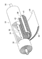
図6は、水処理装置10の縦断面図である。
FIG. 6 is a longitudinal sectional view of the
なお、図6において、海水の流れ方向が矢印で示されている。また、図7(A)は、図6のA−A′線に沿う断面図である。図7(B)は、図6のB−B′線に沿う断面図である。図7(C)は、図6のC−C′線に沿う断面図である。図7(D)は、図6のD−D′線に沿う断面図である。図7(E)は、図6のE−E′線に沿う断面図である。図7(F)は、図6のF−F′線に沿う断面図である。 In FIG. 6, the flow direction of seawater is indicated by arrows. FIG. 7A is a cross-sectional view taken along the line AA ′ of FIG. FIG. 7B is a cross-sectional view taken along the line BB ′ of FIG. FIG. 7C is a cross-sectional view taken along the line CC ′ of FIG. FIG. 7D is a cross-sectional view taken along the line DD ′ of FIG. FIG. 7E is a cross-sectional view taken along the line EE ′ of FIG. FIG. 7F is a cross-sectional view taken along the line FF ′ of FIG.
図6、図7に示すように、実施の形態の水処理装置10は、海水を一次処理する一次処理部50と、一次処理部50によって処理された海水を二次処理する二次処理部52とが円筒状の容器54に並設して収容されている。一次処理部50は、容器54の内周壁面54Aに沿って等間隔で配置された4台のモジュール26、26…によって構成され、これらの4台のモジュール26、26…は、各々の中心軸が容器54の中心軸に対して平行に配置されている。また、二次処理部52は、容器54の中心軸に沿って配置された1本のモジュール26′によって構成され、このモジュール26′は、その中心軸が容器54の中心軸に合致した位置に配置されている。
As shown in FIGS. 6 and 7, the
また、図7では、一次処理部50のモジュール26の径と二次処理部52のモジュール26′の径が略等しいように図示しているが、一次処理部50の処理水量と二次処理部52の処理水量の比に応じてモジュール26、26′の径を適宜選択し、二次処理部52のモジュール26′の径を一次処理部50のモジュール26の径より大きく選定してもよい。なお、一次処理部50の、モジュール26は、ベッセル24に収納した形態であってもよく、ベッセル24に収納せず、複数のエレメント22、22…を直列に接続した形態でもよい。図6、図7には後者のモジュール26が示されている。
Further, in FIG. 7, the diameter of the
実施の形態の水処理装置10によれば、一次処理部50と二次処理部52とを容器54に並設して収容することで、一次処理部50と二次処理部52とを連結する送液管を無くしている。これにより、水処理装置10によれば、送液管を有する水処理装置と比較して、装置設備のコンパクト化を図ることができるとともに、設備費用も削減することができる。なお、実施の形態では、二段処理(一次処理部50+二次処理部52)のみについて説明したが、本発明は、更に三段処理以上にも適用することが可能である。
According to the
水処理装置10では、送液管を無くすことで容器54が必要となるが、この容器54は耐久年数が送液管ほど長く要求されない。よって、容器54の材質は高価なスーパーステンレスではなく、高水圧に耐え得る材質(FRP等)でよい。
In the
また、図6に示すように容器54には、容器54内に海水を導入する導入管56と、導入管56から導入された海水を一次処理部50に導入する導入流路58と、一次処理部50によって処理された一次濃縮水(海水:被処理水)を二次処理部52に折り返して導入する後次処理部供給流路60とが備えられている。すなわち、この容器54によれば、一次処理部50を通過した一次濃縮水が、後次処理部供給流路60を介して二次処理部52に導入されることにより、一次処理部50を通過する海水の流れ方向Aと、二次処理部52を通過する一次濃縮水の流れ方向Bとが逆方向に設定されている。
Further, as shown in FIG. 6, the
この容器54によれば、図1のタンク12から導入管56を介して供給された海水は、導入流路58を介して一次処理部50の4台のモジュール26、26…に導かれる。そして、海水は、4台のモジュール26、26…のRO膜28、28…を順次透過したのち前述の如く各々の集水管34、34…に集水されて各々の排出管30、30…から容器54の外部に一次透過水として排出される。また、一次処理部50のRO膜28、28…を透過しなかった一次濃縮水は、後次処理部供給流路60に導入され、ここで折り返されて二次処理部52のモジュール26′に導入される。そして、二次処理部52のRO膜28、28…を通過することで、二次透過水と二次濃縮水(海水:被処理水)とに分離され、二次透過水が、二次処理部52のモジュール26′の排出管31から容器54の外部に排出されるまた、二次処理部52のRO膜28、28…を透過しなかった二次濃縮水は、後次被処理水排出管62を介して容器54の外部に排出される。
According to this
なお、図6に示す二次処理部52の排出管31は、一次処理部50の排出管30と反対方向に備えられているが、本発明の実施にあたって同じ方向に設けても、また両側に設けても特に差し支えなく、周辺の配管設計に応じて適宜選択することができる。ただし、例えば分離水の濃度が比較的高くなる二次処理部52の排出管31を後処理に連結する場合は、一次処理部50の排出管30と反対側に独立設置することが好ましい。
Although the
実施の形態の水処理装置10は、一次処理部50を通過する海水の流れ方向Aと、二次処理部52を通過する一次濃縮水の流れ方向Bとを、容器54内で逆方向に設定しているので,双方の流れ方向を同一とした場合の容器と比較して、径は若干大きくなるが、軸方向に無用に長くならず、コンパクトになる。
The
なお、一次処理部50のモジュール26、26…の各々の排出管30、30…から排出された一次濾過水は、容器54の端部に設けられているタンク64に貯留された後、排出管66を介してタンク64の外部に排出される。
The primary filtered water discharged from the
ところで、前述の如く実施の形態の容器54は円筒状に構成され、一次処理部50の4台のモジュール26、26…は、容器54の内周壁面54Aに沿って4台配置され、二次処理部52では、容器54の中心軸に沿ってモジュール26′が1台配置されている。
Incidentally, as described above, the
二次処理部52に導入される一次濃縮水は、一次処理部50において一次透過水が排出されているため、一次処理部50に導入される初期の海水よりも量が少ない。つまり、二次処理部52は一次処理部50よりも少ない台数で対応できることになる。よって、設置台数の多い一次処理部50のモジュール26、26…を、スペースの広い容器54の内周壁面54Aに沿って配置し、設置台数の少ない二次処理部52のモジュール26′を容器54の中心軸に沿って配置する。これにより、容器54内のスペースを有効利用して必要最小限の一次処理部50側のモジュール26、26…と二次処理部52側のモジュール26′を配置することができる。
The primary concentrated water introduced into the
なお、二次処理部52のモジュール26′の台数は1台に限定されるものではなく、図8及び図9の如く二次処理部52の4台のモジュール26′、26′…を容器54の中心軸の周りに4台配置してもよい。一次処理部50のモジュール26、26…は、容器54の内周壁面54Aに沿って8台配置されている。
Note that the number of
また、図6に示すように容器54の導入流路58には、導入管56から導入された海水を一次処理部50の4台のモジュール26、26…に向けて分散させる多孔板(分散部材)68が設けられている。この多孔板68に開口された多数の孔70、70…は図7(B)に示すように、多孔板68の中心から外周に向うに従って、その径が大きくなるように構成されている。
Further, as shown in FIG. 6, a porous plate (dispersing member) that disperses seawater introduced from the
孔70の径が上述の如く異なる多孔板68の海水分散作用によって、導入管56から導入された海水は、容器54の内周壁面54Aに沿って配置された一次処理部50の4台のモジュール26、26…に向けて均等に分散する。これにより、一次処理部50による海水の処理効率が向上する。また、導入流路58において均等に分散した前記海水は、図7(C)に示す隔壁板72の孔74、74…を介して4台のモジュール26、26…に供給される。これらの孔74、74…は、モジュール26の端部外形円内に多数開口されている。
Seawater introduced from the
導入管56は、容器54の外周面に接続される以外に、RO膜28の軸方向と同じ向きに接続してもよい。また、排出管66の向きも適宜変更可能である。更に、二次濃縮水の後次被処理水排出管62を、二次透過水の後次分離水排出管31と同軸上に真っ直ぐ配置してもよい。
The
図10は、容器54を8台設置した実施の形態の水処理装置10の構造図である。これに対して、図11は従来の水処理装置100の構造図であり、一次処理部102を構成する40台のモジュール104、104…が示されている。これらの各2台のモジュール104、104が、図12に示す二次処理部106の1台のモジュール108に送液管110を介して連結されている。
FIG. 10 is a structural diagram of the
図11の水処理装置100によれば、主管112に供給された海水は4本のヘッダ管114、114…に分配され、これらのヘッダ管114、114から各導入管116、116を介して一次処理部102の40台のモジュール104、104…に供給される。そして、40台のモジュール104、104…を通過した一次濃縮水は、図12に示した送液管110を介して二次処理部106のモジュール108に供給される。したがって、図11に示した水処理装置100によれば、スーパーステンレス製の高価な送液管110が20本必要となる。
11, the seawater supplied to the
これに対して図10に示した実施の形態の水処理装置10によれば、主管76に供給された海水は2本の枝管78、78に分配され、これらの枝管78、78から各導入管56、56…を介して容器54、54…に供給される。海水は各容器54、54…内で一次処理及び二次処理される。
On the other hand, according to the
このように図10に示した実施の形態の水処理装置10は、図11、図12に示した従来の水処理装置100と比較して、装置設備のコンパクト化を図ることができるとともに、多数本の送液管110が不要になるので、設備資用も削減できることが分かる。
As described above, the
なお、一次処理部のモジュール26と二次処理部のモジュール26′の配置、及びサイズは、上述した形態に限定されるものではない。例えば図13に示すように、容器54の内周面に沿って一次処理部のモジュール26を複数配置し、その内側に、モジュール26よりも大径なモジュール26′を配置した形態でもよい。この形態によれば、二次処理部を複数のモジュールで構成する際のモジュール間のデッドスペースを省くことができ、装置全体の寸法をコンパクト化させることができる。
The arrangement and size of the
また、モジュール26、26′の導入管56及び排出管30、31の配置上の制約がある場合には、図14に示すように、上下方向に複数のモジュール26を配置し、その両側にモジュール26′を配置してもよい。
Further, when there are restrictions on the arrangement of the
一方、一次処理部のモジュール26、26…の膜面積は、二次処理部のモジュール26′の膜面積の1倍以上5倍以下であることが好ましい。
On the other hand, the membrane area of the
また、一次処理部のモジュール26、26…、及び二次処理部のモジュール26′において、それぞれの被処理水入口流量に対する被処理水出口流量は、1/5以上であり、かつ、一次処理部のモジュール26、26…の分離水流量が二次処理部のモジュール26′の分離水量の1倍以上5倍以下であることが好ましい。
Further, in the
一次処理部、二次処理部がともに同等の性能を有する膜分離プロセスである場合、膜分離プロセスに応じて膜面積あたりの分離水量の最大値が決まっているため、一次処理部における分離量を被処理水量から減じた値が、二次処理部に供給され、更に分離水が得られることとなる。また、クロスフローで分離を行う場合は、分離水量に対する被処理水供給量の最大値と被処理水排出量の最小値を決定する必要がある。具体的には、RO膜28で二段処理を行う場合は、一次処理水の被処理水供給量に対して二次処理水の被処理水排水量が1/5以上であることが必要である。
When the primary treatment unit and the secondary treatment unit are both membrane separation processes having equivalent performance, the maximum amount of separated water per membrane area is determined according to the membrane separation process. The value subtracted from the amount of water to be treated is supplied to the secondary treatment unit, and further separated water is obtained. Moreover, when performing separation by cross flow, it is necessary to determine the maximum value of the treated water supply amount and the minimum value of the treated water discharge amount with respect to the separated water amount. Specifically, when performing the two-stage treatment with the
よって、一次処理部の膜面積が二次処理部の膜面積の1倍以上5倍以下であることが好ましい。また、海水淡水化の場合は、一次処理部の被処理水に比べて二次処理部の被処理水は濃度上昇による浸透圧増加が生じるので、一次処理部の膜面積が二次処理部の膜面積に対して1.5〜3倍程度であることが好ましい。これを実現する好適な手段としては、中心軸に沿ったモジュールを大径に構成することによって、中心軸周りに一次処理部、中心軸に沿って二次処理部をバランスよく配置し、更には、容器内のスペースも有効に活用することが可能となり、非常に好ましい実施態様である。 Therefore, it is preferable that the film area of the primary processing unit is 1 to 5 times the film area of the secondary processing unit. In addition, in the case of seawater desalination, since the osmotic pressure increases due to the increase in concentration of the water to be treated in the secondary treatment part compared to the water to be treated in the primary treatment part, the membrane area of the primary treatment part is the same as that of the secondary treatment part. It is preferably about 1.5 to 3 times the membrane area. As a preferable means for realizing this, by configuring the module along the central axis to have a large diameter, the primary processing unit is arranged around the central axis, and the secondary processing unit is arranged along the central axis in a balanced manner. The space in the container can be effectively used, which is a very preferable embodiment.
また、一次処理部、及び二次処理部における分離膜の阻止性能が、一次処理部よりも二次処理部が高いことが好ましい。 Moreover, it is preferable that the secondary processing unit has a higher performance of blocking the separation membrane in the primary processing unit and the secondary processing unit than in the primary processing unit.
一次処理部に比べて二次処理部の被処理水は濃縮されているため、一次処理部よりも阻止性能が高い分離膜を二次処理部に適用すると、一次処理部と二次処理部の分離水質を均一化できるため好ましい。また、一時処理部の分離水と二次処理部の分離水を個別に利用又は処理する場合、一次処理部よりも阻止性能が低い分離膜を二次処理部に適用すると、阻止性能が同一の分離膜を用いた場合と比較して、二次処理部の分離水を増加させることができるので好ましい。 Since the water to be treated in the secondary treatment unit is concentrated compared to the primary treatment unit, when a separation membrane having a higher blocking performance than the primary treatment unit is applied to the secondary treatment unit, the primary treatment unit and the secondary treatment unit This is preferable because the quality of the separated water can be made uniform. In addition, when the separation water of the temporary treatment unit and the separation water of the secondary treatment unit are separately used or treated, when a separation membrane having a prevention performance lower than that of the primary treatment unit is applied to the secondary treatment unit, the prevention performance is the same. Compared with the case where a separation membrane is used, it is preferable because the separation water in the secondary treatment unit can be increased.
実施の形態では、RO膜を使用して海水を淡水化処理する水処理装置について説明したが、分離膜はRO膜に限定されるものではない。すなわち、分離膜を使用して被処理水を水処理する装置であれば、本発明の構成を適用できる。また、被処理水は海水に限定されるものではなく、RO膜等の分離膜もしくはその他の分離プロセスを使用して、水道水や下水を処理した再生水等の水中の溶存物質、濁質、微生物等を除去する水処理装置であっても、本発明の構成を適用できる。 In the embodiment, the water treatment apparatus that desalinates seawater using the RO membrane has been described, but the separation membrane is not limited to the RO membrane. That is, the configuration of the present invention can be applied to any apparatus that uses a separation membrane to treat water to be treated. In addition, the water to be treated is not limited to seawater, but dissolved substances, turbidity, microorganisms in water such as reclaimed water treated with tap water or sewage using separation membranes such as RO membranes or other separation processes Even if it is a water treatment apparatus which removes etc., the structure of this invention is applicable.
10…装置、12…タンク、14…高圧ポンプ、16…透過水、18…濃縮水、20…淡水化処理システム、22…エレメント、24…ベッセル、26…一次処理部のモジュール、26′…二次処理部のモジュール、28…RO膜、30…排出管、31…後次分離水排出管、32…膜ユニット、34…集水管、36…透孔、38…スペーサー、40…スペーサー、50…一次処理部、52…二次処理部、54…容器、54A…内周壁面、56…導入管、58…導入流路、60…後次処理部供給流路、62…後次被処理水排出管、64…タンク、66…排出管、68…多孔板、70…孔、72…隔壁板、74…孔、76…主管、78…枝管、100…水処理装置、102…一次処理部、104…モジュール、106…二次処理部、108…モジュール、110…送液管、112…技管、114…ヘッダ管、A…海水流れ方向、B…一次処理水の流れ方向
DESCRIPTION OF
Claims (11)
前記複数の水処理部は、前段の水処理部で分離されず通過した被処理水が次段の水処理部の被処理水となるように多段接続され、
前記複数段の水処理部が容器に並設して収容され、
前記前段の水処理部によって前記被処理水から分離された分離水を前記容器から排出する排出管が前記容器に貫通して配置され、
前記次段の水処理部によって前記被処理水から分離された後次分離水を前記容器から排出する後次分離水排出管が前記容器に貫通して配置され、
前記次段の水処理部で分離されず通過した前記被処理水を前記容器から排出する後次被処理水排出管が前記容器に貫通して配置されていることを特徴とする水処理装置。 A water treatment device comprising a plurality of water treatment units for treating at least treated water, wherein the water treatment unit comprises a plurality of stages,
The plurality of water treatment units are connected in multiple stages so that the water to be treated that has passed without being separated in the water treatment unit of the previous stage becomes the water to be treated of the water treatment unit of the next stage,
The plurality of stages of water treatment units are accommodated side by side in a container ,
A discharge pipe for discharging the separated water separated from the treated water by the water treatment unit in the previous stage from the container is disposed through the container,
A subsequent separated water discharge pipe for discharging the separated water separated from the treated water by the water treatment unit in the next stage from the container is disposed through the container;
A water treatment apparatus, wherein a subsequent treated water discharge pipe for discharging the treated water that has passed without being separated by the water treatment unit at the next stage is disposed through the container .
Priority Applications (2)
| Application Number | Priority Date | Filing Date | Title |
|---|---|---|---|
| JP2011113790A JP5687561B2 (en) | 2010-09-06 | 2011-05-20 | Water treatment equipment |
| PCT/JP2011/070003 WO2012033011A1 (en) | 2010-09-06 | 2011-09-02 | Water treatment device |
Applications Claiming Priority (3)
| Application Number | Priority Date | Filing Date | Title |
|---|---|---|---|
| JP2010199157 | 2010-09-06 | ||
| JP2010199157 | 2010-09-06 | ||
| JP2011113790A JP5687561B2 (en) | 2010-09-06 | 2011-05-20 | Water treatment equipment |
Publications (3)
| Publication Number | Publication Date |
|---|---|
| JP2012076073A JP2012076073A (en) | 2012-04-19 |
| JP2012076073A5 JP2012076073A5 (en) | 2014-03-13 |
| JP5687561B2 true JP5687561B2 (en) | 2015-03-18 |
Family
ID=45810612
Family Applications (1)
| Application Number | Title | Priority Date | Filing Date |
|---|---|---|---|
| JP2011113790A Active JP5687561B2 (en) | 2010-09-06 | 2011-05-20 | Water treatment equipment |
Country Status (2)
| Country | Link |
|---|---|
| JP (1) | JP5687561B2 (en) |
| WO (1) | WO2012033011A1 (en) |
Families Citing this family (10)
| Publication number | Priority date | Publication date | Assignee | Title |
|---|---|---|---|---|
| JP5998383B2 (en) | 2010-07-28 | 2016-09-28 | 株式会社リコー | Transmission management system, transmission system, transmission management method, and program |
| JP6399896B2 (en) * | 2014-10-31 | 2018-10-03 | 株式会社日立製作所 | Reverse osmosis processing equipment |
| CN108623064A (en) * | 2017-03-22 | 2018-10-09 | 嵊州市晟祥盈净水设备有限公司 | A kind of purifier that purification efficiency is high |
| CN107129042B (en) * | 2017-05-19 | 2022-10-04 | 浙江建设职业技术学院 | Water treatment device |
| WO2019180789A1 (en) * | 2018-03-19 | 2019-09-26 | 三菱重工エンジニアリング株式会社 | Water treatment device and water treatment method |
| JP7119623B2 (en) * | 2018-06-18 | 2022-08-17 | 三浦工業株式会社 | Water treatment equipment connection unit |
| JP7158254B2 (en) * | 2018-11-19 | 2022-10-21 | 日東電工株式会社 | How to purify tap water |
| KR102391733B1 (en) * | 2020-04-06 | 2022-04-28 | 두산에너빌리티 주식회사 | Reverse osmosis apparatus and seawater desalination system comprising the same |
| KR102414918B1 (en) * | 2020-06-03 | 2022-06-29 | 두산에너빌리티 주식회사 | Reverse osmosis system and seawater desalination system comprising the same |
| KR102357812B1 (en) * | 2020-06-03 | 2022-01-28 | 두산중공업 주식회사 | Reverse osmosis apparatus and seawater desalination system comprising the same |
Family Cites Families (3)
| Publication number | Priority date | Publication date | Assignee | Title |
|---|---|---|---|---|
| JPS53147682A (en) * | 1977-05-30 | 1978-12-22 | Nitto Electric Ind Co Ltd | Water permeating and collecting material for separator for liquid treatment |
| JPS6021312U (en) * | 1983-07-20 | 1985-02-14 | 木下 栄 | Filtration filter device |
| JP2009240852A (en) * | 2008-03-28 | 2009-10-22 | Toray Ind Inc | Filter medium cartridge, switching device for water purifier and water purifier |
-
2011
- 2011-05-20 JP JP2011113790A patent/JP5687561B2/en active Active
- 2011-09-02 WO PCT/JP2011/070003 patent/WO2012033011A1/en active Application Filing
Also Published As
| Publication number | Publication date |
|---|---|
| JP2012076073A (en) | 2012-04-19 |
| WO2012033011A1 (en) | 2012-03-15 |
Similar Documents
| Publication | Publication Date | Title |
|---|---|---|
| JP5687561B2 (en) | Water treatment equipment | |
| JP5923294B2 (en) | Reverse osmosis processing equipment | |
| JP6020168B2 (en) | Membrane filtration method and membrane filtration apparatus | |
| US8795527B2 (en) | Filtration system | |
| WO2012086479A1 (en) | Reverse osmosis processing device | |
| JP2018171563A (en) | Reverse osmosis treatment device and reverse osmosis treatment method | |
| US10583401B2 (en) | Integrated ultrafiltration and reverse osmosis desalination systems | |
| KR102414918B1 (en) | Reverse osmosis system and seawater desalination system comprising the same | |
| JP2006263542A (en) | Water making apparatus and water making method | |
| JP6344114B2 (en) | Water treatment apparatus and water treatment equipment cleaning method | |
| KR102460002B1 (en) | Reverse osmosis apparatus and seawater desalination system comprising the same | |
| CN111867700A (en) | Integrated composite filter module for water purifier | |
| US11648496B2 (en) | Treatment module and operating method therefor | |
| US11498860B2 (en) | Reverse osmosis apparatus and seawater desalination system having the same | |
| WO2018159561A1 (en) | Reverse osmosis treatment device and reverse osmosis treatment method | |
| JP2008183513A (en) | Water purifying apparatus | |
| WO2011102443A1 (en) | Water treatment device | |
| WO2011102464A1 (en) | Water processing device | |
| KR102391733B1 (en) | Reverse osmosis apparatus and seawater desalination system comprising the same | |
| EP3894050B1 (en) | Arrangement in cross-flow membrane separation unit | |
| JP3878934B2 (en) | Water purification equipment | |
| JP2016215205A (en) | Reverse osmosis treatment device | |
| JP5996057B2 (en) | Reverse osmosis processing equipment | |
| WO2011102438A1 (en) | Water processing device |
Legal Events
| Date | Code | Title | Description |
|---|---|---|---|
| A711 | Notification of change in applicant |
Free format text: JAPANESE INTERMEDIATE CODE: A712 Effective date: 20130523 |
|
| A621 | Written request for application examination |
Free format text: JAPANESE INTERMEDIATE CODE: A621 Effective date: 20140106 |
|
| A521 | Request for written amendment filed |
Free format text: JAPANESE INTERMEDIATE CODE: A523 Effective date: 20140124 |
|
| A131 | Notification of reasons for refusal |
Free format text: JAPANESE INTERMEDIATE CODE: A131 Effective date: 20141002 |
|
| A521 | Request for written amendment filed |
Free format text: JAPANESE INTERMEDIATE CODE: A523 Effective date: 20141126 |
|
| TRDD | Decision of grant or rejection written | ||
| A01 | Written decision to grant a patent or to grant a registration (utility model) |
Free format text: JAPANESE INTERMEDIATE CODE: A01 Effective date: 20150105 |
|
| A61 | First payment of annual fees (during grant procedure) |
Free format text: JAPANESE INTERMEDIATE CODE: A61 Effective date: 20150122 |
|
| R150 | Certificate of patent or registration of utility model |
Ref document number: 5687561 Country of ref document: JP Free format text: JAPANESE INTERMEDIATE CODE: R150 |
|
| R250 | Receipt of annual fees |
Free format text: JAPANESE INTERMEDIATE CODE: R250 |
|
| R250 | Receipt of annual fees |
Free format text: JAPANESE INTERMEDIATE CODE: R250 |
|
| R250 | Receipt of annual fees |
Free format text: JAPANESE INTERMEDIATE CODE: R250 |
|
| R250 | Receipt of annual fees |
Free format text: JAPANESE INTERMEDIATE CODE: R250 |
|
| R250 | Receipt of annual fees |
Free format text: JAPANESE INTERMEDIATE CODE: R250 |
|
| R250 | Receipt of annual fees |
Free format text: JAPANESE INTERMEDIATE CODE: R250 |
|
| R250 | Receipt of annual fees |
Free format text: JAPANESE INTERMEDIATE CODE: R250 |