JP5679476B2 - Game machine - Google Patents
Game machine Download PDFInfo
- Publication number
- JP5679476B2 JP5679476B2 JP2013056507A JP2013056507A JP5679476B2 JP 5679476 B2 JP5679476 B2 JP 5679476B2 JP 2013056507 A JP2013056507 A JP 2013056507A JP 2013056507 A JP2013056507 A JP 2013056507A JP 5679476 B2 JP5679476 B2 JP 5679476B2
- Authority
- JP
- Japan
- Prior art keywords
- effect
- variable display
- variation pattern
- big hit
- symbol
- Prior art date
- Legal status (The legal status is an assumption and is not a legal conclusion. Google has not performed a legal analysis and makes no representation as to the accuracy of the status listed.)
- Active
Links
- 230000000694 effects Effects 0.000 claims description 1427
- 230000008859 change Effects 0.000 claims description 182
- 230000015654 memory Effects 0.000 claims description 143
- 238000004519 manufacturing process Methods 0.000 claims description 129
- 238000003860 storage Methods 0.000 claims description 95
- 238000009795 derivation Methods 0.000 claims description 12
- 238000000034 method Methods 0.000 description 353
- 230000008569 process Effects 0.000 description 349
- 239000000872 buffer Substances 0.000 description 105
- 238000013461 design Methods 0.000 description 79
- 238000012545 processing Methods 0.000 description 58
- 230000004044 response Effects 0.000 description 44
- 230000001276 controlling effect Effects 0.000 description 41
- 238000005034 decoration Methods 0.000 description 34
- 238000001514 detection method Methods 0.000 description 32
- 230000005540 biological transmission Effects 0.000 description 24
- 230000009467 reduction Effects 0.000 description 23
- 238000010586 diagram Methods 0.000 description 10
- 238000013500 data storage Methods 0.000 description 9
- 230000014759 maintenance of location Effects 0.000 description 9
- 230000001965 increasing effect Effects 0.000 description 8
- 238000004904 shortening Methods 0.000 description 8
- 230000006870 function Effects 0.000 description 7
- 230000009471 action Effects 0.000 description 6
- 238000009877 rendering Methods 0.000 description 6
- 238000004458 analytical method Methods 0.000 description 5
- 230000015572 biosynthetic process Effects 0.000 description 5
- 238000003786 synthesis reaction Methods 0.000 description 5
- 238000004891 communication Methods 0.000 description 4
- 210000003128 head Anatomy 0.000 description 4
- 239000000758 substrate Substances 0.000 description 4
- 230000008602 contraction Effects 0.000 description 3
- 238000011161 development Methods 0.000 description 3
- 230000004048 modification Effects 0.000 description 3
- 238000012986 modification Methods 0.000 description 3
- 230000001105 regulatory effect Effects 0.000 description 3
- 230000005236 sound signal Effects 0.000 description 3
- 102100025639 Sortilin-related receptor Human genes 0.000 description 2
- 101710126735 Sortilin-related receptor Proteins 0.000 description 2
- 241000722921 Tulipa gesneriana Species 0.000 description 2
- 238000010924 continuous production Methods 0.000 description 2
- 238000003745 diagnosis Methods 0.000 description 2
- 238000005286 illumination Methods 0.000 description 2
- 239000004973 liquid crystal related substance Substances 0.000 description 2
- 238000007726 management method Methods 0.000 description 2
- 239000011159 matrix material Substances 0.000 description 2
- 230000002250 progressing effect Effects 0.000 description 2
- 238000004088 simulation Methods 0.000 description 2
- 102100035353 Cyclin-dependent kinase 2-associated protein 1 Human genes 0.000 description 1
- 101000710013 Homo sapiens Reversion-inducing cysteine-rich protein with Kazal motifs Proteins 0.000 description 1
- 101000661807 Homo sapiens Suppressor of tumorigenicity 14 protein Proteins 0.000 description 1
- 241001465754 Metazoa Species 0.000 description 1
- 102100029860 Suppressor of tumorigenicity 20 protein Human genes 0.000 description 1
- 230000005856 abnormality Effects 0.000 description 1
- 230000001133 acceleration Effects 0.000 description 1
- 238000013459 approach Methods 0.000 description 1
- OMFRMAHOUUJSGP-IRHGGOMRSA-N bifenthrin Chemical compound C1=CC=C(C=2C=CC=CC=2)C(C)=C1COC(=O)[C@@H]1[C@H](\C=C(/Cl)C(F)(F)F)C1(C)C OMFRMAHOUUJSGP-IRHGGOMRSA-N 0.000 description 1
- 230000008033 biological extinction Effects 0.000 description 1
- 230000033228 biological regulation Effects 0.000 description 1
- 230000004397 blinking Effects 0.000 description 1
- 244000309464 bull Species 0.000 description 1
- 239000003086 colorant Substances 0.000 description 1
- 238000004040 coloring Methods 0.000 description 1
- 238000012790 confirmation Methods 0.000 description 1
- 230000002708 enhancing effect Effects 0.000 description 1
- 239000000284 extract Substances 0.000 description 1
- 238000003825 pressing Methods 0.000 description 1
- 230000008685 targeting Effects 0.000 description 1
- 230000002123 temporal effect Effects 0.000 description 1
- 230000007704 transition Effects 0.000 description 1
Images


Description
本発明は、パチンコ遊技機等の遊技機に係り、詳しくは、始動条件が成立した後に開始条件が成立したことに基づいて、各々が識別可能な複数種類の識別情報を可変表示する複数の可変表示部を有する可変表示装置を備え、複数の可変表示部にて順次に導出表示した識別情報の可変表示結果が予め定められた特定表示結果となった後に、遊技者にとって有利な特定遊技状態に制御する遊技機に関する。 The present invention relates to a gaming machine such as a pachinko gaming machine, and more specifically, a plurality of variable information that variably displays a plurality of types of identification information that can be identified based on the start condition being satisfied after the start condition is satisfied. A variable display device having a display unit, and after a variable display result of identification information sequentially derived and displayed by a plurality of variable display units becomes a predetermined specific display result, a specific gaming state advantageous to a player is obtained. It relates to a gaming machine to be controlled.
パチンコ遊技機等の遊技機においては、液晶表示装置(以下LCD:Liquid Crystal Display)等の表示装置上に所定の識別情報(以下、表示図柄)を更新表示やスクロール表示させることで変動可能とする可変表示を行い、その表示結果により所定の遊技価値を付与するか否かを決定する、いわゆる可変表示ゲームによって遊技興趣を高めたものが数多く提供されている。 In a gaming machine such as a pachinko machine, it can be changed by displaying predetermined identification information (hereinafter referred to as a display symbol) on a display device such as a liquid crystal display (hereinafter referred to as “LCD”) by updating or scrolling. There are a number of games that have been enhanced by a so-called variable display game that performs variable display and determines whether or not to give a predetermined game value based on the display result.
可変表示ゲームには、前述の表示装置を画像表示装置として用いることにより行うものがある。こうした可変表示ゲームでは、始動入賞口を通過する遊技球の検出(可変表示の実行条件が成立したこと)に基づいて表示図柄の変動を開始させ、表示図柄の変動が完全に停止した際の停止図柄(確定図柄)の態様が特定表示態様となっている場合を「大当り」とするゲームである。可変表示ゲームにおいて「大当り」となると、大入賞口またはアタッカと呼ばれる特別電動役物を開放状態とし、遊技者に対して遊技球の入賞が極めて容易となる状態を一定時間継続的に提供する。この状態を「特定遊技状態」あるいは「大当り遊技状態」という。 Some variable display games are played by using the above display device as an image display device. In such a variable display game, the change of the display symbol is started based on the detection of the game ball passing through the start winning opening (the execution condition of the variable display is satisfied), and the stop when the change of the display symbol is completely stopped. A game in which a case of a symbol (determined symbol) is a specific display mode is a “big hit”. When a “big hit” occurs in the variable display game, a special electric combination called a big prize opening or an attacker is opened, and a state in which a game ball can be won extremely easily is provided to a player for a certain period of time. This state is referred to as “specific game state” or “hit game state”.
こうした遊技機としては、表示図柄の可変表示がリーチ表示態様となった後に、ランダムに決定されたリーチ切換タイミングにてリーチ表示態様を切り換える表示制御が行われるものが提案されている(例えば、特許文献1)。 As such a gaming machine, there has been proposed one in which display control is performed for switching the reach display mode at a randomly determined reach switching timing after the variable display of the display symbols has reached the reach display mode (for example, patents). Reference 1).
上記特許文献1に記載の技術によると、リーチ表示態様を切り換えるには、表示図柄の可変表示がリーチ表示態様とならなければならない。そのため、リーチ表示態様となる以前には、「大当り」の可変表示結果に対する期待感を高めることが困難になる。
According to the technique described in
また、リーチ表示態様が切り換えられた場合でも、可変表示結果が「大当り」とはならない場合がある。そのため、多様な演出動作が行われても「大当り」の可変表示結果とならずに、遊技の興趣が減退するおそれがある。 Even when the reach display mode is switched, the variable display result may not be “big hit”. Therefore, even if various presentation operations are performed, there is a possibility that the interest of the game may be reduced without obtaining a “big hit” variable display result.
この発明は、上記実状に鑑みてなされたものであり、演出動作の切り換えによる演出効果を高めて、遊技の興趣を向上させることができる遊技機を提供することを目的とする。 The present invention has been made in view of the above circumstances, and an object of the present invention is to provide a gaming machine that can enhance the effect of the effect by switching the effect operation and improve the interest of the game.
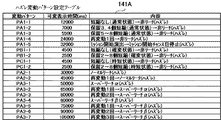
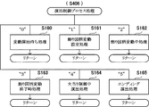
(1)上記目的を達成するため、本願の請求項に係る遊技機は、各々が識別可能な複数種類の識別情報(例えば飾り図柄など)を可変表示する可変表示装置(例えば画像表示装置5など)に導出表示した前記識別情報の可変表示結果が予め定められた特定表示結果(例えば大当り組合せの最終停止図柄など)となった後に、遊技者にとって有利な特定遊技状態(例えば大当り遊技状態など)に制御する遊技機(例えばパチンコ遊技機1など)であって、前記特定遊技状態に制御するか否かを、前記識別情報の可変表示結果が導出表示される以前に決定する事前決定手段(例えばCPU103がステップS250の処理を実行する部分など)と、複数の可変表示パターンを記憶する可変表示パターン記憶手段(例えばハズレ変動パターン設定テーブル141A及び大当り変動パターン設定テーブル141B〜141Dなど)と、前記事前決定手段による決定結果に基づいて、前記複数の可変表示パターンのうちからいずれかを選択する可変表示パターン選択手段(例えばCPU103がステップS261〜S274の処理を実行する部分など)と、前記可変表示パターン選択手段によって選択された可変表示パターンに対応する演出動作を実行する演出実行手段(例えば演出制御用CPU120がステップS406の演出制御プロセス処理を実行する部分や、表示制御部123、音声制御基板13、ランプ制御基板14など)とを備え、前記可変表示パターン記憶手段に記憶される前記複数の可変表示パターンには、リーチ状態とした後に特定表示結果を導出表示する全演出大当り可変表示パターン(例えば変動パターンPA4−1、PA4−2、PA5−1〜PA5−3、PA6−1〜PA6−5、PA7−1、PA7−2、PA8−1〜PA8−3、PA9−1〜PA9−5など)と、前記識別情報の可変表示中における予め定められた演出切換タイミングにて、前記全演出大当り可変表示パターンによる演出動作と同一の演出動作から前記全演出大当り可変表示パターンによる演出動作とは異なる特定演出に切り換わり、特定表示結果を導出表示する突発大当り可変表示パターン(例えば変動パターンPT1−1〜PT1−4、PT2−1〜PT2−7、PT3−1〜PT3−6など)とが含まれ、前記突発大当り可変表示パターンには、リーチ状態となるより前に前記演出切換タイミングとなるリーチ前突発大当り可変表示パターン(例えば変動パターンPT1−1〜PT1−4、PT2−1、PT2−3〜PT2−5、PT2−7、PT3−1、PT3−3、PT3−4など)と、リーチ状態となった後に前記演出切換タイミングとなるリーチ後突発大当り可変表示パターン(例えば変動パターンPT2−2、PT2−6、PT3−2、PT3−5、PT3−6など)とを含む、複数の突発大当り可変表示パターンがあり、前記特定遊技状態には、少なくとも第1特定遊技状態と当該第1特定遊技状態よりも遊技者にとって有利な第2特定遊技状態とが含まれ、前記突発大当り可変表示パターンによる可変表示が実行されたときに、前記全演出大当り可変表示パターンによる可変表示が実行されたときよりも高い割合で、前記第2特定遊技状態に制御される。
(1) In order to achieve the above object, the gaming machine according to the claims of the present application provides a variable display device (for example, the image display device 5) that variably displays a plurality of types of identification information (for example, decorative symbols) that can be identified. ) After the variable display result of the identification information derived and displayed becomes a predetermined specific display result (for example, the final stop symbol of the jackpot combination), the specific gaming state (for example, the jackpot gaming state) that is advantageous to the player Pre-determining means (for example, a
このような構成においては、リーチ前突発大当り可変表示パターンにより、リーチ状態となるより前に演出切換タイミングとなって特定演出に切り換わり特定表示結果が導出表示される。また、リーチ後突発大当り可変表示パターンにより、リーチ状態となった後に演出切換タイミングとなって特定演出に切り換わり特定表示結果が導出表示される。これにより、演出動作が特定演出に切り換わるときには特定表示結果が導出表示され、特定表示結果となることの意外性を高めて、遊技の興趣を向上させることができる。また、リーチ状態となるより前でも特定演出に切り換えられるため、識別情報が可変表示される期間の全体にわたり特定表示結果となることに対する期待感を高めて、遊技の興趣を向上させることができる。 In such a configuration, a reach before sudden jackpot variable display pattern, switched specific display results specific effect becomes effect switching timing before the reach state is Ru derived displayed. Furthermore, the reach after sudden jackpot variable display pattern, the specific effect on the switched specific display result becomes effect switching timing after a reach state is Ru derived displayed. Thereby, when the effect operation is switched to the specific effect, the specific display result is derived and displayed, and the unexpectedness of being the specific display result can be enhanced and the interest of the game can be improved. In addition, since it is switched to the specific effect even before reaching the reach state, it is possible to enhance the expectation that the specific display result will be obtained over the entire period during which the identification information is variably displayed, thereby improving the interest of the game.
(2)上記(1)の遊技機において、遊技者が操作可能な操作手段を備え、前記演出実行手段は、前記突発大当り可変表示パターンによる操作促進演出中の操作有効期間内に前記操作手段が操作されたタイミングにて、前記特定演出への切り換えを行い、当該特定演出が終了したときに特定表示結果を導出表示させた後、予め定められた前記突発大当り可変表示パターンによる前記識別情報の可変表示時間が経過するまで当該特定表示結果の導出表示を継続する、ようにしてもよい。
(3)上記(1)又は(2)の遊技機において、前記特定遊技状態に制御される可能性を予告する予告演出を実行する予告演出実行手段を備える、ようにしてもよい。
(4)上記(1)から(3)のいずれかの遊技機において、前記演出実行手段は、リーチ状態となるより前に該リーチ状態となることを予告するリーチ予告演出を実行可能であり(例えば演出制御用CPU120がステップS527にて決定した予告パターンによりステップS544の処理を実行する部分など)、前記突発大当り可変表示パターンには、前記リーチ予告演出が実行されるタイミングを前記演出切換タイミングとするリーチ予告時突発大当り可変表示パターン(例えば変動パターンPT1−2、PT1−3など)が含まれるように構成されてもよい。
(2) In the gaming machine of (1), the player includes operation means that can be operated by the player, and the effect executing means is operated within the operation effective period during the operation promotion effect by the sudden big hit variable display pattern. After switching to the specific effect at the operated timing and deriving and displaying a specific display result when the specific effect ends, the identification information can be changed by the predetermined sudden hit variable display pattern. The derivation display of the specific display result may be continued until the display time elapses.
(3) The gaming machine according to (1) or (2) may further include a notice effect executing means for executing a notice effect for notifying the possibility of being controlled to the specific gaming state.
(4) In any one of the above gaming machines (1) to (3), the effect executing means can execute a reach notice effect for notifying that the reach state is reached before the reach state is reached ( For example, in the sudden big hit variable display pattern, the timing at which the reach notice effect is executed is referred to as the effect switching timing in the sudden big hit variable display pattern. It may be configured to include a sudden big hit variable display pattern (for example, variation patterns PT1-2, PT1-3, etc.) at the time of reach notice.
このような構成においては、リーチ予告演出が実行されるタイミングで特定演出に切り換わり、特定演出の終了時に特定表示結果を導出表示することができる。これにより、リーチ予告演出が実行されるときに特定表示結果となる意外性や期待感を高めて、遊技の興趣を向上させることができる。 In such a configuration, it is possible to switch to the specific effect at the timing when the reach notice effect is executed, and to display the specific display result at the end of the specific effect. Thereby, the unexpectedness and expectation which become a specific display result when the reach notice effect is executed can be enhanced, and the interest of the game can be improved.
(5)上記(1)から(4)のいずれかの遊技機において、前記演出実行手段は、識別情報の可変表示を開始してから一旦仮停止表示させた後、前記識別情報の再可変表示を開始させる再可変表示動作を所定回実行可能であり(例えば演出制御用CPU120が変動パターンPA1−4、PA2−2、PA3−2、PA3−3、PA3−5〜PA3−7などに応じてステップS506で決定した演出制御パターンによりステップS544の処理を実行する部分など)、前記突発大当り可変表示パターンには、前記再可変表示動作中における予め定められたタイミングを前記演出切換タイミングとする再可変表示動作時突発大当り可変表示パターン(例えば変動パターンPT1−4、PT2−3、PT2−5、PT2−7、PT3−1、PT3−3、PT3−4など)が含まれるように構成されてもよい。
( 5 ) In any one of the above gaming machines (1) to (4) , the effect executing means temporarily displays the identification information and then temporarily stops the display, and then displays the identification information again. Can be executed a predetermined number of times (for example, the
このような構成においては、再可変表示動作中における予め定められたタイミングで特定演出に切り換わり、特定演出の終了時に特定表示結果を導出表示することができる。これにより、再可変表示動作が実行されるときに特定表示結果となる意外性や期待感を高めて、遊技の興趣を向上させることができる。 In such a configuration, it is possible to switch to the specific effect at a predetermined timing during the re-variable display operation, and to display and display the specific display result at the end of the specific effect. Thereby, the unexpectedness and expectation which become a specific display result when a re-variable display operation is performed can be improved, and the interest of a game can be improved.
(6)上記(1)から(5)のいずれかの遊技機において、前記演出実行手段は、前記識別情報の可変表示中において、所定の達成条件が提示され、該達成条件を成立させると前記特定遊技状態に制御されるミッション演出を複数回の開始条件の成立に対応する複数回の前記識別情報の可変表示にわたって実行可能であり(例えば演出制御用CPU120がステップS562の処理を実行した後にステップS556、S564の処理を実行するまで、ステップS506で決定した演出制御パターンによりステップS544の処理を実行する部分など)、前記突発大当り可変表示パターンには、前記ミッション演出が開始されることを報知するミッション開始演出中における予め定められたタイミングを前記演出切換タイミングとするミッション開始演出時突発大当り可変表示パターン(例えば変動パターンPT2−1、PT2−4など)が含まれるように構成されてもよい。
( 6 ) In the gaming machine according to any one of (1) to (5) , the performance executing means presents a predetermined achievement condition during variable display of the identification information, and when the achievement condition is satisfied, The mission effect controlled in the specific gaming state can be executed over a plurality of variable display of the identification information corresponding to the establishment of a plurality of start conditions (for example, after the
このような構成においては、ミッション開始演出中における予め定められたタイミングで特定演出に切り換わり、特定演出の終了時に特定表示結果を導出表示することができる。これにより、ミッション開始演出が実行されるときに特定表示結果となる意外性や期待感を高めて、遊技の興趣を向上させることができる。 In such a configuration, it is possible to switch to the specific effect at a predetermined timing during the mission start effect, and to derive and display the specific display result at the end of the specific effect. Thereby, the unexpectedness and expectation which become a specific display result when the mission start effect is executed can be enhanced, and the interest of the game can be improved.
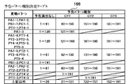
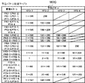
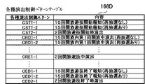
(7)上記(1)から(6)のいずれかの遊技機においては、遊技領域に設けられて遊技者にとって有利な第1状態と遊技者にとって不利な第2状態とに変化する可変入賞手段(例えば特別可変入賞球装置7など)と、前記第1特定遊技状態として、前記可変入賞手段を第1期間(例えば0.5秒など)が経過するまで前記第1状態に変化させるラウンドの実行回数が第1回数(例えば「2」など)となる特定遊技状態(例えば大当り種別が「突確」である場合における2ラウンド大当り状態など)に制御する第1特定遊技状態制御手段(例えばCPU103がステップS254にて大入賞口開放回数最大値を「2」に設定した後、ステップS114〜S117の処理を実行する部分など)と、前記第2特定遊技状態として、各ラウンドで前記可変入賞手段を前記第1状態に変化させる期間が前記第1期間よりも長い第2期間(例えば29秒など)となる、または、ラウンドの実行回数が前記第1回数よりも多い第2回数(例えば「15」など)となり、当該特定遊技状態の終了後には、前記事前決定手段によって前記特定遊技状態に制御すると決定される確率が当該特定遊技状態とは異なる通常状態よりも向上した高確率状態(例えば確変状態など)となる特定遊技状態(例えば大当り種別が「確変」である場合における15ラウンド大当り状態など)に制御する第2特定遊技状態制御手段(例えばCPU103がステップS254にて大入賞口開放回数最大値を「15」に設定した後、ステップS114〜S117の処理を実行する部分など)とを備え、前記事前決定手段は、さらに前記特定遊技状態として前記第1特定遊技状態と前記第2特定遊技状態のいずれに制御するかを決定し(例えばCPU103がステップS253の処理を実行する部分など)、前記可変表示パターン記憶手段に記憶される複数の特定可変表示パターンには、前記全演出大当り可変表示パターンにおける演出動作とは異なる突確演出を実行する突確大当り可変表示パターン(例えば変動パターンPF1−1〜PF1−4など)と、前記突確大当り可変表示パターンに比べて可変表示時間が短い可変表示パターンであって、前記突確大当り可変表示パターンと同様に前記突確演出を開始した後、当該突確演出中における予め定められたタイミングを前記演出切換タイミングとして前記特定演出に切り換わり特定表示結果を導出表示する突確演出時突発大当り可変表示パターン(例えば変動パターンPT1−5、PT4−5など)とが含まれ、前記全演出大当り可変表示パターンと前記突確演出時突発大当り可変表示パターンは、前記事前決定手段によって前記第1特定遊技状態に制御すると決定されたときに、前記可変表示パターン選択手段により選択可能となり(例えば図19に示すように、変動パターンPA4−1、PA4−2、PA5−1〜PA5−3、PA6−1〜PA6−5、PA7−1、PA7−2、PA8−1〜PA8−3、PA9−1〜PA9−5が変動パターン種別CA3−1〜CA3−4のいずれかに応じて決定可能となる部分や、図20(A)に示すように変動パターンPT1−5、PT4−5が変動パターン種別CA4−1に応じて決定可能となる部分など)、前記突確大当り可変表示パターンは、前記事前決定手段によって前記第2特定遊技状態に制御すると決定されたときに、前記可変表示パターン選択手段により選択可能となる(例えば図20(B)に示すように、変動パターンPF1−1〜PF1−4が変動パターン種別CA5−1及びCA5−2のいずれかに応じて決定可能となる部分など)ように構成されてもよい。
( 7 ) In the gaming machine according to any one of (1) to (6 ) above, variable winning means that is provided in the gaming area and changes between a first state that is advantageous to the player and a second state that is disadvantageous to the player. (For example, a special variable winning ball apparatus 7) and execution of a round in which the variable winning means is changed to the first state until a first period (for example, 0.5 seconds) elapses as the first specific gaming state. A first specific game state control means (for example, the
このような構成においては、突確演出中における予め定められたタイミングで特定演出に切り換わり、特定演出の終了時に特定表示結果を導出表示することができる。これにより、突確演出が実行されるときに特定表示結果となる意外性や期待感を高めて、遊技の興趣を向上させることができる。 In such a configuration, it is possible to switch to the specific effect at a predetermined timing during the surprise effect, and to display the specific display result at the end of the specific effect. Thereby, the unexpectedness and expectation which become a specific display result when a surprise effect is performed can be improved, and the interest of a game can be improved.
以下、図面を参照しつつ、本発明の一実施形態を詳細に説明する。図1は、本実施の形態におけるパチンコ遊技機の正面図であり、主要部材の配置レイアウトを示す。パチンコ遊技機(遊技機)1は、大別して、遊技盤面を構成する遊技盤(ゲージ盤)2と、遊技盤2を支持固定する遊技機用枠(台枠)3とから構成されている。遊技盤2には、ガイドレールによって囲まれた、ほぼ円形状の遊技領域が形成されている。この遊技領域には、遊技媒体としての遊技球が、所定の打球発射装置から発射されて打ち込まれる。
Hereinafter, an embodiment of the present invention will be described in detail with reference to the drawings. FIG. 1 is a front view of a pachinko gaming machine according to the present embodiment and shows an arrangement layout of main members. The pachinko gaming machine (gaming machine) 1 is roughly composed of a gaming board (gauge board) 2 constituting a gaming board surface and a gaming machine frame (base frame) 3 for supporting and fixing the
遊技盤2の所定位置(図1に示す例では、遊技領域の右側方)には、第1特別図柄表示装置4Aと、第2特別図柄表示装置4Bとが設けられている。第1特別図柄表示装置4Aと第2特別図柄表示装置4Bはそれぞれ、例えば7セグメントやドットマトリクスのLED(発光ダイオード)等から構成され、可変表示ゲームの一例となる特図ゲームにおいて、各々が識別可能な複数種類の識別情報(特別識別情報)である特別図柄(「特図」ともいう)を、変動可能に表示(可変表示)する。例えば、第1特別図柄表示装置4Aと第2特別図柄表示装置4Bはそれぞれ、「0」〜「9」を示す数字や「−」を示す記号等から構成される複数種類の特別図柄を可変表示する。なお、第1特別図柄表示装置4Aや第2特別図柄表示装置4Bにて表示される特別図柄は、「0」〜「9」を示す数字や「−」を示す記号等から構成されるものに限定されず、例えば7セグメントのLEDにおいて点灯させるものと消灯させるものとの組合せを異ならせた複数種類の点灯パターンが、複数種類の特別図柄として予め設定されていればよい。複数種類の特別図柄には、それぞれに対応した図柄番号が付されている。一例として、「0」〜「9」を示す数字それぞれには、「0」〜「9」の図柄番号が付され、「−」を示す記号には、「10」の図柄番号が付されていればよい。以下では、第1特別図柄表示装置4Aにより可変表示される特別図柄を「第1特図」ともいい、第2特別図柄表示装置4Bにより可変表示される特別図柄を「第2特図」ともいう。
A first special
遊技盤2における遊技領域の中央付近には、画像表示装置5が設けられている。画像表示装置5は、例えばLCD(液晶表示装置)等から構成され、各種の演出画像を表示する表示領域を形成している。画像表示装置5の表示領域では、特図ゲームにおける第1特別図柄表示装置4Aによる第1特図の可変表示や第2特別図柄表示装置4Bによる第2特図の可変表示のそれぞれに対応して、例えば3つといった複数に分割された可変表示部となる飾り図柄表示部にて、各々が識別可能な複数種類の識別情報(装飾識別情報)である飾り図柄を可変表示する。この飾り図柄の可変表示も、可変表示ゲームに含まれる。
An
一例として、画像表示装置5の表示領域には、「左」、「中」、「右」の飾り図柄表示部5L、5C、5Rが配置されている。そして、特図ゲームにおいて、第1特別図柄表示装置4Aによる第1特図の可変表示と、第2特別図柄表示装置4Bによる第2特図の可変表示とのうち、いずれかの可変表示が開始されることに対応して、「左」、「中」、「右」の飾り図柄表示部5L、5C、5Rの全部において飾り図柄の可変表示(例えば上下方向あるいは左右方向のスクロール表示など)が開始される。その後、特図ゲームにおける可変表示結果として確定特別図柄が停止表示(完全停止表示)されるときに、画像表示装置5における「左」、「中」、「右」の各飾り図柄表示部5L、5C、5Rにて、飾り図柄の可変表示結果となる確定飾り図柄(最終停止図柄)が停止表示(完全停止表示)される。なお、「左」、「中」、「右」の各飾り図柄表示部5L、5C、5Rは、画像表示装置5の表示領域内で移動可能とされ、飾り図柄を縮小あるいは拡大して表示することができるようにしてもよい。特別図柄や飾り図柄が完全停止表示されたときには、各図柄の可変表示における表示結果が確定的に表示され、それ以後は今回の可変表示が進行しないことを遊技者が認識できる表示状態となる。これに対して、飾り図柄の可変表示を開始してから可変表示結果となる確定飾り図柄が完全停止表示されるまでの可変表示中には、飾り図柄の変動速度が「0」となって、飾り図柄が停留して表示され、例えば微少な揺れや伸縮などを生じさせる表示状態となることがある。このような表示状態は、仮停止表示ともいい、可変表示における表示結果が確定的に表示されていないものの、スクロール表示や更新表示による飾り図柄の変動が進行していないことを遊技者が認識可能となる。なお、仮停止表示には、微少な揺れや伸縮なども生じさせず、所定時間(例えば1秒間)よりも短い時間だけ、飾り図柄を完全停止表示することなどが含まれてもよい。完全停止表示や仮停止表示のように、特別図柄や飾り図柄の変動が進行していないことを遊技者が認識できる程度に表示図柄を停止表示することは、導出表示ともいう。
As an example, “left”, “middle”, and “right” decorative
「左」、「中」、「右」の各飾り図柄表示部5L、5C、5Rにて可変表示される飾り図柄には、例えば8種類の図柄(英数字「1」〜「8」あるいは漢数字「一」〜「八」、英文字「A」〜「H」、所定のモチーフに関連する8個のキャラクタを示す演出画像、数字や文字あるいは記号とキャラクタとを組み合わせた演出画像など。なお、キャラクタを示す演出画像は、例えば人物や動物、これら以外の物体、もしくは、文字などの記号、あるいは、その他の任意の図形を示す画像であればよい。)が含まれていればよい。また、こうした8種類の飾り図柄の他に、ブランク図柄(大当り組合せを構成しない図柄)が含まれていてもよい。飾り図柄のそれぞれには、対応する図柄番号が付されている。例えば、「1」〜「8」を示す英数字それぞれに対して、「1」〜「8」の図柄番号が付されている。なお、可変表示される飾り図柄の種類数は、8種類のものに限定されず、任意の複数種類からなる飾り図柄であればよい。
The decorative symbols variably displayed on the “left”, “middle”, and “right” decorative
飾り図柄の変動中には、「左」、「中」、「右」の各飾り図柄表示部5L、5C、5Rにおいて、例えば図柄番号が小さいものから大きいものへと順次に、上方から下方へ、あるいは、右側から左側へと、流れるようなスクロール表示が行われる。そして、図柄番号が最大(例えば「8」)である飾り図柄が表示されると、続いて図柄番号が最小(例えば「1」)である飾り図柄が表示される。あるいは、飾り図柄表示部5L、5C、5Rのうち少なくともいずれか1つにおいて、図柄番号が大きいものから小さいものへとスクロール表示を行って、図柄番号が最小である飾り図柄が表示されると、続いて図柄番号が最大である飾り図柄が表示されるようにしてもよい。
While the decorative symbols are changing, in the decorative
画像表示装置5の表示領域には、始動入賞記憶表示部5Hも配置されている。始動入賞記憶表示部5Hでは、可変表示の保留数(特図保留記憶数)を特定可能に表示する保留記憶表示が行われる。ここで、可変表示の保留は、普通入賞球装置6Aが形成する第1始動入賞口や普通可変入賞球装置6Bが形成する第2始動入賞口に遊技球が進入(始動入賞)したときに発生する。すなわち、特図ゲームや飾り図柄の可変表示といった可変表示ゲームを実行するための始動条件(「実行条件」ともいう)は成立したが、先に成立した開始条件に基づく可変表示ゲームが実行中であることやパチンコ遊技機1が大当り遊技状態に制御されていることなどにより、可変表示ゲームを開始するための開始条件は成立していないときに、成立した始動条件に対応する可変表示の保留が行われる。
In the display area of the
一例として、始動入賞記憶表示部5Hには、始動入賞の発生に基づき先に始動条件が成立した可変表示ゲームから順に左から右へと、表示色が変更される複数の表示部位が設けられている。そして、第1始動入賞口に遊技球が進入したことに基づき第1特別図柄表示装置4Aにおける第1特図を用いた特図ゲームの始動条件(第1始動条件)が成立したときには、通常非表示(透過色)となっている表示部位のうちの1つ(例えば非表示となっている表示部位のうち左端の表示部位)を青色表示に変化させる。また、第2始動入賞口に遊技球が進入したことに基づき第2特別図柄表示装置4Bにおける第2特図を用いた特図ゲームの始動条件(第2始動条件)が成立したときには、通常非表示となっている表示部位のうちの1つを赤色表示に変化させる。その後、第1特図を用いた特図ゲームの開始条件(第1開始条件)と第2特図を用いた特図ゲームの開始条件(第2開始条件)のいずれかが成立したときには、例えば左端の表示部位における表示を除去するとともに、各表示部位における表示を1つずつ左方向に移動させる。このとき、青色表示や赤色表示に変化していた表示部位のうちの1つ(例えば表示色が変化していた表示部位のうち右端の表示部位)は、非表示に戻る。ここで、保留記憶表示を行う際に、可変表示ゲームの始動条件が成立したことに基づく特図保留記憶数は特定できたものの、その始動条件が第1始動条件であるか第2始動条件であるかを特定できない場合に、例えば特図保留記憶数に対応する個数の表示部位を灰色表示に変化させることなどにより、特図保留記憶数の表示態様を所定の表示態様に変更してもよい。
As an example, the start winning memory display section 5H is provided with a plurality of display parts whose display colors are changed from left to right in order from the variable display game in which the start condition is established based on the occurrence of the start winning. Yes. When the start condition (first start condition) of the special figure game using the first special figure in the first special
なお、始動入賞記憶表示部5Hでは、特図保留記憶数を示す数字を表示することなどにより、特図保留記憶数を遊技者等が認識できるようにしてもよい。始動入賞記憶表示部5Hとともに、あるいは始動入賞記憶表示部5Hに代えて、特図保留記憶数を表示する表示器を設けるようにしてもよい。図1に示す例では、始動入賞記憶表示部5Hとともに、第1特別図柄表示装置4A及び第2特別図柄表示装置4Bの上部に、特図保留記憶数を特定可能に表示するための第1保留表示器25Aと第2保留表示器25Bとが設けられている。第1保留表示器25Aは、普通入賞球装置6Aが形成する第1始動入賞口に進入した有効始動入賞球数としての第1保留記憶数を特定可能に表示する。第2保留表示器25Bは、普通可変入賞球装置6Bが形成する第2始動入賞口に進入した有効始動入賞球数としての第2保留記憶数を特定可能に表示する。第1保留表示器25Aと第2保留表示器25Bはそれぞれ、例えば第1保留記憶数と第2保留記憶数のそれぞれにおける上限値(例えば「4」)に対応した個数(例えば4個)のLEDを含んで構成されている。
In the start winning memory display unit 5H, a number indicating the special figure reserved memory number may be displayed so that the player or the like can recognize the special figure reserved memory number. In addition to the start winning memory display unit 5H, or instead of the start winning memory display unit 5H, a display for displaying the number of special figure reserved memories may be provided. In the example shown in FIG. 1, together with the start winning memory display section 5H, the first hold for displaying the number of special figure hold memories identifiable on the upper part of the first special
画像表示装置5の表示領域には、飾り図柄とは異なる識別情報としての色図柄を可変表示する色図柄表示エリアが設けられていてもよい。一例として、色図柄表示エリアには、第1特別図柄表示装置4Aによる第1特図を用いた特図ゲームが開始されるときに、色図柄の変動(例えば表示色の更新表示)が開始される「左」の色図柄表示部と、第2特別図柄表示装置4Bによる第2特図を用いた特図ゲームが開始されるときに、色図柄の変動が開始される「右」の色図柄表示部とが含まれていればよい。そして、特図ゲームにおいて可変表示結果となる確定特別図柄が完全停止表示されるときには、色図柄の変動が終了して、色図柄の可変表示結果となる確定色図柄が完全停止表示される。「左」及び「右」の色図柄表示部にて可変表示される色図柄には、例えば4種類の図柄(「黄色」、「緑色」、「赤色」、「青色」など)といった、複数種類の色図柄が含まれていればよい。色図柄のそれぞれには、対応する図柄番号が付されている。一例として、「黄色」、「緑色」、「赤色」、「青色」の色図柄それぞれに対して、「1」〜「4」の図柄番号が付されていればよい。
The display area of the
画像表示装置5の下方には、普通入賞球装置6Aと、普通可変入賞球装置6Bとが設けられている。普通入賞球装置6Aは、例えば所定の玉受部材によって常に一定の開放状態に保たれる第1始動入賞口を形成する。普通可変入賞球装置6Bは、所定の普通電動役物用ソレノイドによって垂直位置となる通常開放状態と傾動位置となる拡大開放状態とに変化する一対の可動翼片を有する電動チューリップ型役物(普通電動役物)を備え、第2始動入賞口を形成する。一例として、普通可変入賞球装置6Bでは、普通電動役物用ソレノイドがオフ状態であるときに可動翼片が垂直位置となることにより、遊技球が第2始動入賞口に進入しにくい通常開放状態となる。その一方で、普通可変入賞球装置6Bでは、普通電動役物用ソレノイドがオン状態であるときに可動翼片が傾動位置となることにより、遊技球が第2始動入賞口に進入しやすい拡大開放状態となる。なお、普通可変入賞球装置6Bは、通常開放状態であるときでも、第2始動入賞口には遊技球が進入可能であるものの、拡大開放状態であるときよりも遊技球が進入する可能性が低くなるように構成してもよい。あるいは、普通可変入賞球装置6Bは、通常開放状態において、例えば第2始動入賞口を閉鎖することなどにより、第2始動入賞口には遊技球が進入しないように構成してもよい。
Below the
普通入賞球装置6Aに形成された第1始動入賞口に進入した遊技球は、例えば図2に示す第1始動口スイッチ22Aによって検出される。普通可変入賞球装置6Bに形成された第2始動入賞口に進入した遊技球は、例えば図2に示す第2始動口スイッチ22Bによって検出される。第1始動口スイッチ22Aによって遊技球が検出されたことに基づき、所定個数(例えば3個)の遊技球が賞球として払い出され、第1保留記憶数が所定の上限値(例えば「4」)以下であれば、第1始動条件が成立する。第2始動口スイッチ22Bによって遊技球が検出されたことに基づき、所定個数(例えば3個)の遊技球が賞球として払い出され、第2保留記憶数が所定の上限値以下であれば、第2始動条件が成立する。なお、第1始動口スイッチ22Aによって遊技球が検出されたことに基づいて払い出される賞球の個数と、第2始動口スイッチ22Bによって遊技球が検出されたことに基づいて払い出される賞球の個数は、互いに同一の個数であってもよいし、異なる個数であってもよい。
A game ball that has entered the first start winning opening formed in the normal
普通入賞球装置6Aと普通可変入賞球装置6Bの下方には、特別可変入賞球装置7が設けられている。特別可変入賞球装置7は、所定の大入賞口扉用ソレノイドによって開閉駆動される大入賞口扉を備え、その大入賞口扉によって開放状態(第1状態)と閉鎖状態(第2状態)とに変化する大入賞口を形成する。一例として、特別可変入賞球装置7では、大入賞口扉用ソレノイドがオフ状態であるときに大入賞口扉が大入賞口を閉鎖状態にする。その一方で、特別可変入賞球装置7では、大入賞口扉用ソレノイドがオン状態であるときに大入賞口扉が大入賞口を開放状態にする。特別可変入賞球装置7に形成された大入賞口に進入した遊技球は、例えば図2に示すカウントスイッチ23によって検出される。カウントスイッチ23によって遊技球が検出されたことに基づき、所定個数(例えば14個)の遊技球が賞球として払い出される。
A special variable winning
遊技盤2の所定位置(図1に示す例では、遊技領域の左側方)には、普通図柄表示器20が設けられている。一例として、普通図柄表示器20は、第1特別図柄表示装置4Aや第2特別図柄表示装置4Bと同様に7セグメントやドットマトリクスのLED等から構成され、特別図柄とは異なる複数種類の識別情報である普通図柄(「普図」あるいは「普通図」ともいう)を変動可能に表示(可変表示)する。このような普通図柄の可変表示は、普図ゲーム(「普通図ゲーム」ともいう)と称される。普通図柄表示器20は、例えば「0」〜「9」を示す数字や「−」を示す記号等から構成される複数種類の普通図柄を可変表示する。複数種類の普通図柄には、それぞれに対応した図柄番号が付されている。一例として、「0」〜「9」を示す数字それぞれには、「0」〜「9」の図柄番号が付され、「−」を示す記号には、「10」の図柄番号が付されていればよい。なお、普通図柄表示器20は、「0」〜「9」を示す数字や「−」を示す記号等を普通図柄として可変表示するものに限定されず、例えば「○」と「×」とを示す装飾ランプ(またはLED)を交互に点灯させることや、「左」、「中」、「右」といった複数の装飾ランプ(またはLED)を所定順序で点灯させることにより、普通図柄を可変表示するものであってもよい。普通図柄表示器20の上方には、普図保留表示器25Cが設けられている。普図保留表示器25Cは、例えば4個のLEDを含んで構成され、通過ゲート41を通過した有効通過球数としての普図保留記憶数を表示する。
A
遊技盤2の表面には、上記の構成以外にも、遊技球の流下方向や速度を変化させる風車及び多数の障害釘が設けられている。また、第1始動入賞口、第2始動入賞口及び大入賞口とは異なる入賞口として、例えば所定の玉受部材によって常に一定の開放状態に保たれる一般入賞口が1つ又は複数設けられてもよい。この場合には、一般入賞口のいずれかに進入した遊技球が所定の一般入賞球スイッチによって検出されたことに基づき、所定個数(例えば10個)の遊技球が賞球として払い出されればよい。遊技領域の最下方には、いずれの入賞口にも進入しなかった遊技球が取り込まれるアウト口が設けられている。遊技機用枠3の左右上部位置には、効果音等を再生出力するためのスピーカ8L、8Rが設けられており、さらに遊技領域周辺部には、遊技効果ランプ9が設けられている。パチンコ遊技機1の遊技領域における各構造物(例えば普通入賞球装置6A、普通可変入賞球装置6B、特別可変入賞球装置7等)の周囲には、装飾用LEDが配置されていてもよい。
In addition to the above-described configuration, the surface of the
遊技機用枠3の右下部位置には、遊技媒体としての遊技球を遊技領域に向けて発射するために遊技者等によって操作される打球操作ハンドル(操作ノブ)が設けられている。例えば、打球操作ハンドルは、遊技者等による操作量(回転量)に応じて遊技球の弾発力を調整する。打球操作ハンドルには、打球発射装置が備える発射モータの駆動を停止させるための単発発射スイッチや、タッチリング(タッチセンサ)が設けられていればよい。遊技領域の下方における遊技機用枠3の所定位置には、賞球として払い出された遊技球や所定の球貸機により貸し出された遊技球を、打球発射装置へと供給可能に保持(貯留)する上皿が設けられている。例えば上皿の上面における手前側の中央位置といった、パチンコ遊技機1の遊技機用枠3における所定位置には、押下操作などにより遊技者が操作可能な操作ボタン30が設置されている。なお、操作ボタン30は、押下操作が可能なものに限定されず、例えば回転型セレクタのような回転操作が可能なものであってもよいし、タッチパネルのように接触操作や押圧操作が可能なものであってもよいし、レバー型スイッチのような傾動操作が可能なものであってもよい。また、操作ボタン30に代えて、例えば赤外線センサやCCDセンサ、CMOSセンサのように、遊技者による所定の操作行為を検出できるセンサを用いてもよい。すなわち、操作ボタン30は、遊技者による所定の操作行為を、機械的、電気的、あるいは、電磁的に、検出できるものであればよい。
At the lower right position of the
普通図柄表示器20による普図ゲームは、遊技領域に設けられた通過ゲート41を通過した遊技球が図2に示すゲートスイッチ21によって検出されたことといった、普通図柄表示器20にて普通図柄の可変表示を実行するための普図始動条件が成立した後に、例えば前回の普図ゲームが終了したことといった、普通図柄の可変表示を開始するための普図開始条件が成立したことに基づいて、開始される。この普図ゲームでは、普通図柄の変動を開始させた後、所定の可変表示時間が経過すると、普通図柄の可変表示結果となる確定普通図柄を完全停止表示する。普通図柄の可変表示時間は、例えば各普図ゲームの開始時に、所定の乱数値を示す数値データを抽出することなどにより、複数種類の可変表示時間のうちで、いずれかに決定されればよい。普図ゲームにおける普通図柄の可変表示結果となる確定普通図柄として、例えば「7」を示す数字といった、特定の普通図柄(普図当り図柄)が停止表示されれば、普通図柄の可変表示結果が「普図当り」となる。その一方、確定普通図柄として、例えば「7」を示す数字以外の数字や記号といった、普図当り図柄以外の普通図柄が停止表示されれば、普通図柄の可変表示結果が「普図ハズレ」となる。普通図柄の可変表示結果が「普図当り」となったことに対応して、普通可変入賞球装置6Bを構成する電動チューリップの可動翼片が傾動位置となる拡大開放制御が行われ、所定時間が経過すると垂直位置に戻る通常開放制御が行われる。
In the normal game with the
第1特別図柄表示装置4Aによる特図ゲームは、普通入賞球装置6Aに形成された第1始動入賞口に進入した遊技球が図2に示す第1始動口スイッチ22Aによって検出されたことなどにより第1始動条件が成立した後に第1開始条件が成立したことに基づいて、開始される。第1開始条件は、例えば前回の特図ゲームや大当り遊技状態が終了したときなどに、第1特図を用いた今回の特図ゲームが開始可能となることにより成立する。第2特別図柄表示装置4Bによる特図ゲームは、普通可変入賞球装置6Bに形成された第2始動入賞口に進入した遊技球が図2に示す第2始動口スイッチ22Bによって検出されたことなどにより第2始動条件が成立した後に第2開始条件が成立したことに基づいて、開始される。第2開始条件は、例えば前回の特図ゲームや大当り遊技状態が終了したときなどに、第2特図を用いた今回の特図ゲームが開始可能となることにより成立する。
The special symbol game by the first special
第1特別図柄表示装置4Aや第2特別図柄表示装置4Bによる特図ゲームでは、特別図柄の可変表示を開始させた後、所定の可変表示時間が経過すると、特別図柄の可変表示結果となる確定特別図柄を完全停止表示する。特別図柄の可変表示時間は、各特図ゲームの開始時に、例えば図5に示すような変動パターン種別決定用の乱数値MR4を示す数値データや、変動パターン決定用の乱数値MR5を示す数値データなどに基づいて決定された変動パターンに対応して、複数種類の可変表示時間のうちで、いずれかに決定される。特図ゲームにおける特別図柄の可変表示結果となる確定特別図柄として、特定の特別図柄(大当り図柄)が停止表示されれば、特定表示結果としての「大当り」となり、大当り図柄以外の特別図柄(ハズレ図柄)が停止表示されれば、非特定表示結果としての「ハズレ」となる。特図ゲームでの可変表示結果が「大当り」になった後には、特定遊技状態としての大当り遊技状態に制御される。この実施の形態におけるパチンコ遊技機1では、一例として、「1」、「3」、「7」を示す数字を大当り図柄とし、「−」を示す記号をハズレ図柄としている。なお、第1特別図柄表示装置4Aによる特図ゲームにおける大当り図柄やハズレ図柄といった各図柄は、第2特別図柄表示装置4Bによる特図ゲームにおける各図柄とは異なる特別図柄となるようにしてもよいし、双方の特図ゲームにおいて共通の特別図柄が大当り図柄やハズレ図柄となるようにしてもよい。
In the special symbol game by the first special
この実施の形態では、大当り図柄となる「1」、「3」、「7」の数字を示す特別図柄のうち、「3」、「7」の数字を示す特別図柄を15ラウンド大当り図柄とし、「1」の数字を示す特別図柄を2ラウンド大当り図柄とする。特図ゲームにおける確定特別図柄として15ラウンド大当り図柄が停止表示された後に制御される第1特定遊技状態としての大当り遊技状態(15ラウンド大当り状態)では、特別可変入賞球装置7の開閉板が、第1期間となる所定期間(例えば29秒間)あるいは所定個数(例えば10個)の入賞球が発生するまでの期間にて大入賞口を開放状態とすることにより、特別可変入賞球装置7を遊技者にとって有利な第1状態に変化させるラウンドが実行される。こうしてラウンド中に大入賞口を開放状態とした開閉板は、遊技盤2の表面を落下する遊技球を受け止め、その後に大入賞口を閉鎖状態とすることにより、特別可変入賞球装置7を遊技者にとって不利な第2状態に変化させて、1回のラウンドを終了させる。15ラウンド大当り状態では、大入賞口の開放サイクルであるラウンドの実行回数が、第1回数(例えば「15」)となる。ラウンドの実行回数が「15」となる15ラウンド大当り状態における遊技は、15回開放遊技とも称される。
In this embodiment, among the special symbols indicating the numbers “1”, “3”, and “7” that are jackpot symbols, the special symbols indicating the numbers “3” and “7” are 15 round jackpot symbols, A special symbol indicating the number “1” is a two-round jackpot symbol. In the big hit gaming state (15 round big hit state) as the first specific gaming state controlled after the 15 round big hit symbol is stopped and displayed as a confirmed special symbol in the special figure game, the open / close plate of the special variable winning
特図ゲームにおける確定特別図柄として2ラウンド大当り図柄が停止表示された後に制御される第2特定遊技状態としての大当り遊技状態(2ラウンド大当り状態)では、各ラウンドで特別可変入賞球装置7を遊技者にとって有利な第1状態に変化させる期間(開閉板により大入賞口を開放状態とする期間)が、15ラウンド大当り状態における第1期間よりも短い第2期間(例えば0.5秒間)となる。また、2ラウンド大当り状態では、ラウンドの実行回数が、15ラウンド大当り状態における第1回数よりも少ない第2回数(例えば「2」)となる。なお、2ラウンド大当り状態では、各ラウンドで大入賞口を開放状態とする期間が第2期間となることと、ラウンドの実行回数が第2回数となることのうち、少なくともいずれか一方が行われるように制御されればよく、それ以外の制御は15ラウンド大当り状態と同様に行われるようにしてもよい。ラウンドの実行回数が「2」となる2ラウンド大当り状態における遊技は、2回開放遊技とも称される。なお、2ラウンド大当り状態では、各ラウンドで特別可変入賞球装置7とは別個に設けられた所定の入賞球装置を、遊技者にとって不利な第2状態から遊技者にとって有利な第1状態に変化させ、所定期間(第1期間または第2期間)が経過した後に第2状態へと戻すようにしてもよい。
In the big hit gaming state (two round big hit state) as the second specific gaming state controlled after the two round big hit symbol is stopped and displayed as the confirmed special symbol in the special figure game, the special variable winning
また、15ラウンド大当り図柄となる「3」、「7」の数字を示す特別図柄のうち、「3」の数字を示す特別図柄が特図ゲームにおける確定特別図柄として停止表示されたことに基づく15ラウンド大当り状態が終了した後には、特別遊技状態の1つとして、通常状態に比べて特図ゲームにおける特別図柄の変動時間(特図変動時間)が短縮される時短状態に制御される。ここで、通常状態とは、大当り遊技状態等の特定遊技状態や時短状態等の特別遊技状態以外の遊技状態のことであり、パチンコ遊技機1の初期設定状態(例えばシステムリセットが行われた場合のように、電源投入後に初期化処理を実行した状態)と同一の制御が行われる。時短状態は、所定回数(例えば100回)の特図ゲームが実行されることと、可変表示結果が「大当り」となることのうち、いずれかの条件が先に成立したときに、終了すればよい。なお、特図ゲームにおける確定特別図柄として15ラウンド大当り図柄のうち「3」の数字を示す特別図柄が停止表示されたことに基づく15ラウンド大当り状態が終了した後には、時短状態とはならずに通常状態となるようにしてもよい。こうした「3」の数字を示す特別図柄のように、特図ゲームにおける確定特別図柄として停止表示されたことに基づく大当り遊技状態が終了した後に時短状態や通常状態に制御される15ラウンド大当り図柄は、通常大当り図柄(「非確変大当り図柄」ともいう)と称される。特図ゲームにおける確定特別図柄が通常大当り図柄となる場合における特別図柄や飾り図柄の可変表示態様は、可変表示結果が「大当り」となる場合における「通常」(「通常大当り」ともいう)の可変表示態様(「大当り種別」ともいう)と称される。
Further, among the special symbols indicating the numbers “3” and “7” which are the 15-round jackpot symbol, the special symbol indicating the number “3” is stopped and displayed as the confirmed special symbol in the
15ラウンド大当り図柄となる「3」、「7」の数字を示す特別図柄のうち、「7」の数字を示す特別図柄が特図ゲームにおける確定特別図柄として停止表示されたことに基づく15ラウンド大当り状態が終了した後や、2ラウンド大当り図柄となる「1」の数字を示す特別図柄が特図ゲームにおける確定特別図柄として停止表示されたことに基づく2ラウンド大当り状態が終了した後には、時短状態とは異なる特別遊技状態の1つとして、例えば通常状態に比べて特図変動時間が短縮されるとともに、継続して確率変動制御(確変制御)が行われる確変状態(高確率遊技状態)に制御される。この確変状態では、各特図ゲームや飾り図柄の可変表示において、可変表示結果が「大当り」となって更に大当り遊技状態に制御される確率が、通常状態よりも高くなるように向上する。このような確変状態は、特図ゲームの実行回数にかかわりなく、次に可変表示結果が「大当り」となるまで継続してもよい。これに対して、確変状態となった後に、所定回数(例えば100回)の特図ゲームが実行されることと、可変表示結果が「大当り」となることのうち、いずれかの条件が先に成立したときに、終了するようにしてもよい。また、確変状態において所定回数の特図ゲームが実行されたり可変表示結果が「大当り」となる以前であっても、特図ゲームが開始されるときに、所定の割合で確変状態が終了することがあるようにしてもよい。 Out of the special symbols showing the numbers “3” and “7” that will be the 15-round jackpot symbol, the 15-round jackpot is based on the special symbol showing the number “7” being stopped and displayed as a confirmed special symbol in the special game. After the state is over, or after the two round jackpot state is over based on the fact that the special symbol indicating the number “1” that becomes the two-round jackpot symbol is stopped and displayed as the confirmed special symbol in the special figure game, As one of the special game states different from the normal game state, for example, the special figure change time is shortened compared to the normal state, and the probability change state (high probability game state) in which probability change control (probability change control) is continuously performed is controlled. Is done. In this probability change state, the variable display result of each special figure game and the decorative symbol variable display is improved so that the probability that the variable display result becomes “big hit” and is further controlled to the big hit gaming state is higher than in the normal state. Such a probability change state may be continued until the next variable display result is a “hit” regardless of the number of executions of the special game. On the other hand, after the certainty change state is reached, any one of the conditions that the special game is executed a predetermined number of times (for example, 100 times) and the variable display result is “big hit” is first. You may make it complete | finish when it is materialized. In addition, even if the special figure game is executed a predetermined number of times in the probability change state or before the variable display result is “big hit”, the probability change state ends at a predetermined rate when the special figure game is started. There may be.
「7」の数字を示す特別図柄のように、特図ゲームにおける確定特別図柄として停止表示されたことに基づく大当り遊技状態が終了した後に確変状態に制御される15ラウンド大当り図柄は、確変大当り図柄と称される。特図ゲームにおける確定特別図柄が確変大当り図柄となる場合における特別図柄や飾り図柄の可変表示態様は、可変表示結果が「大当り」となる場合における「確変」(「確変大当り」ともいう)の可変表示態様(「大当り種別」ともいう)と称される。「1」の数字を示す特別図柄のように、特図ゲームにおける確定特別図柄として停止表示されたことに基づく大当り遊技状態が終了した後に確変状態に制御される2ラウンド大当り図柄は、突確大当り図柄と称される。特図ゲームにおける確定特別図柄が突確大当り図柄となる場合における特別図柄や飾り図柄の可変表示態様は、可変表示結果が「大当り」となる場合における「突確」(「突確大当り」あるいは「突然確変大当り」ともいう)の可変表示態様(「大当り種別」ともいう)と称される。 Like the special symbol indicating the number “7”, the 15-round jackpot symbol controlled to the probable change state after the jackpot gaming state based on being stopped and displayed as the confirmed special symbol in the special symbol game is a probabilistic big hit symbol. It is called. The variable display mode of special symbols and decorative symbols when the confirmed special symbol in the special figure game becomes a probable big hit symbol is variable "probable change" (also called "probable big hit") when the variable display result is "big hit". It is referred to as a display mode (also referred to as “big hit type”). Like the special symbol indicating the number “1”, the two-round big hit symbol controlled to the probable change state after the big hit gaming state based on being stopped and displayed as the confirmed special symbol in the special figure game is a sudden big hit symbol. It is called. The variable display mode of special symbols and decorative symbols when the confirmed special symbol in the special figure game is a sudden big hit symbol is “surprise” (“surprise big hit” or “sudden probability big hit” when the variable display result is “big hit”. ")" As a variable display mode (also referred to as "big hit type").
確変状態や時短状態では、普通図柄表示器20による普図ゲームにおける普通図柄の可変表示時間を通常状態のときよりも短くする制御や、各回の普図ゲームで普通図柄の可変表示結果が「普図当り」となる確率を通常状態のときよりも向上させる制御、可変表示結果が「普図当り」となったことに基づく普通可変入賞球装置6Bにおける可動翼片の傾動時間を通常状態のときよりも長くする制御、その傾動回数を通常状態のときよりも増加させる制御といった、第2始動入賞口に遊技球が進入する可能性を高めて第2始動条件が成立しやすくなることで遊技者にとって有利となる制御が行われる。なお、確変状態や時短状態では、これらの制御のいずれか1つが行われるようにしてもよいし、複数の制御が組み合わせられて行われるようにしてもよい。確変状態と時短状態とでは、行われる制御が異なるようにしてもよいし、行われる制御の組合せ(同一の制御を含んでも含まなくてもよい)が異なるようにしてもよい。
In the probabilistic state and the short time state, the normal
画像表示装置5の表示画面では、第1特別図柄表示装置4Aや第2特別図柄表示装置4Bによる特別図柄の可変表示に対応して、飾り図柄の可変表示が行われる。すなわち、画像表示装置5の表示画面では、第1開始条件と第2開始条件のいずれか一方が成立したことに基づいて、例えば「左」、「中」、「右」の飾り図柄表示部5L、5C、5Rにおける全部にて飾り図柄の加速表示(全図柄加速表示)を行い、所定速度に達すれば、飾り図柄の定速表示(全図柄定速表示)を行う。こうした全図柄加速表示や全図柄定速表示は、「左」、「中」、「右」の飾り図柄表示部5L、5C、5Rの全部にて飾り図柄を可変表示する全図柄変動に含まれる。こうした全図柄変動の後、例えば「左」→「右」→「中」といった所定順序で飾り図柄の減速表示(各図柄減速表示)を行い、変動速度が「0」となれば、飾り図柄を停留して表示する一方で、例えば微少な揺れや伸縮などを生じさせる仮停止表示を行う。そして、飾り図柄の可変表示を開始してからの経過時間が変動パターンなどに基づいて決定された可変表示時間に達したときには、可変表示結果となる確定飾り図柄を完全停止表示する。なお、確定飾り図柄を停止表示する手順としては、「左」、「中」、「右」の飾り図柄表示部5L、5C、5Rにおいて所定順序で飾り図柄を減速表示するものに限定されず、「左」、「中」、「右」の各飾り図柄表示部5L、5C、5Rにおいて同時に確定飾り図柄となる飾り図柄を減速表示(全図柄減速表示)するものが含まれていてもよい。
On the display screen of the
全図柄変動が開始された後には、「左」、「中」、「右」の飾り図柄表示部5L、5C、5Rのうち全部または一部の飾り図柄表示部にて、飾り図柄をリーチ表示状態で導出表示することがある。ここで、リーチ表示状態とは、画像表示装置5の表示画面にて導出表示された飾り図柄が大当り組合せの一部を構成しているときに未だ導出表示されていない飾り図柄(「リーチ変動図柄」ともいう)については変動が継続している表示状態、あるいは、全部または一部の飾り図柄が大当り組合せの全部または一部を構成しながら同期して変動している表示状態のことである。具体的には、「左」、「中」、「右」の飾り図柄表示部5L、5C、5Rにおける一部(例えば「左」及び「右」の飾り図柄表示部5L、5Rなど)では予め定められた大当り組合せを構成する飾り図柄(例えば「7」の英数字を示す飾り図柄)が導出表示されているときに未だ導出表示されていない残りの飾り図柄表示部(例えば「中」の飾り図柄表示部5Cなど)では飾り図柄が変動している表示状態、あるいは、「左」、「中」、「右」の飾り図柄表示部5L、5C、5Rにおける全部または一部で飾り図柄が大当り組合せの全部または一部を構成しながら同期して変動している表示状態である。また、リーチ表示状態となったことに対応して、画像表示装置5の表示画面に飾り図柄とは異なるアニメーション画像や実写画像といった演出画像を表示させたり、背景画像の表示態様を変化させたり、飾り図柄の変動態様を変化させたりすることがある。このような演出画像の表示や背景画像の表示態様の変化、飾り図柄の変動態様の変化を、リーチ演出表示(あるいは単にリーチ演出)という。リーチ演出の中には、それが出現すると、通常のリーチ演出(ノーマルリーチ)に比べて大当りが発生しやすい(高い確率で大当りとなる)ように設定されたものがある。このような特別のリーチ演出を、スーパーリーチ演出(あるいは単に「スーパーリーチ」)ともいう。一例として、スーパーリーチとなるリーチ演出には、ノーマルリーチと同様のリーチ演出を所定時間が経過するまで行ってから、例えば背景画像の表示態様や、表示されるキャラクタ、飾り図柄の変動方向といった飾り図柄の変動態様のうち、少なくともいずれか1つがリーチ表示状態となる以前やノーマルリーチのときとは異なるものとなることにより、演出態様が変化(いわゆる「発展」)して、スーパーリーチに特有のリーチ演出における導入部分が開始されるものが含まれていればよい。また、スーパーリーチとなるリーチ演出には、飾り図柄がリーチ表示状態で導出表示されたときに、ノーマルリーチと同様のリーチ演出を行うことなく、スーパーリーチに特有のリーチ演出における導入部分が開始されるものが含まれていてもよい。
After all symbols change is started, the decorative symbols are reach-displayed on all or some of the decorative
飾り図柄の可変表示中には、リーチ演出とは異なり、飾り図柄の可変表示状態がリーチ表示状態となる可能性があることや、可変表示結果が「大当り」となる可能性があることを、飾り図柄の可変表示態様などにより遊技者に報知するための特定演出が実行されることがある。この実施の形態では、「擬似連」の特定演出となる演出動作が、実行可能に設定されている。ここで、「擬似連」の特定演出では、特別図柄や飾り図柄の可変表示を開始するための第1開始条件あるいは第2開始条件が1回成立したことに対応して、全図柄変動が開始されてから、「左」、「中」、「右」の飾り図柄表示部5L、5C、5Rの全部にて順次または同時に飾り図柄を仮停止表示させた後、「左」、「中」、「右」の飾り図柄表示部5L、5C、5Rの全部にて飾り図柄の再可変表示を開始させる再可変表示動作(再変動)を、所定回実行する演出動作である。一例として、「擬似連」の特定演出では、「左」、「中」、「右」の飾り図柄表示部5L、5C、5Rにて、図3(A)に示すような擬似連チャンス目GC1〜GC8として予め定められた複数種類の飾り図柄の組合せのいずれかが仮停止表示される。そして、再変動の回数が多くなるに従って、可変表示結果が「大当り」となる割合が高くなるように設定されていればよい。これにより、遊技者は、擬似連チャンス目GC1〜GC8のいずれかが仮停止表示されることにより、「擬似連」の特定演出が行われることを認識でき、再変動の回数が多くなるに従って、可変表示結果が「大当り」となる期待感が高められる。この実施の形態では、「擬似連」の特定演出において、再変動が1回〜3回行われることにより、第1開始条件あるいは第2開始条件が1回成立したことに基づき、飾り図柄の可変表示があたかも2回〜4回続けて開始されたかのように見せることができる。以下では、第1開始条件あるいは第2開始条件が1回成立したことに基づき、飾り図柄の可変表示が開始されてから最終停止図柄が停止表示されるまでに実行される再変動の回数(例えば「1」〜「3」)を擬似連中再変動回数ともいい、「擬似連」の特定演出が実行されることにより見かけ上で連続して実行される飾り図柄の変動回数(例えば「2」〜「4」)を擬似連回数ともいう。すなわち、擬似連回数は、擬似連中再変動回数に「1」を加えた数値となる。
During the variable display of decorative designs, unlike the reach production, the variable display state of decorative designs may become the reach display state, and the variable display result may be a “hit”, There may be a case where a specific effect for informing the player is given in accordance with a variable display mode of the decorative design. In this embodiment, an effect operation that is a specific effect of the “pseudo train” is set to be executable. Here, in the specific effect of “pseudo-ream”, all symbol variations start in response to the first start condition or the second start condition for starting variable display of special symbols and decorative symbols being established once. Then, the decorative symbols are displayed on the “left”, “middle”, and “right” decorative
「擬似連」の特定演出が実行される飾り図柄の可変表示中には、擬似連続変動の進行に伴って、例えば画像表示装置5の表示画面における所定位置に予め用意されたキャラクタを示す演出画像を表示することや、スピーカ8L、8Rから所定の音声(特別音)を出力させること、遊技効果ランプ9を所定の点灯パターンで点灯させること、遊技領域内あるいは遊技領域外に設けられた演出用役物が備える複数の可動部材を動作させることといった、所定の演出動作が実行されてもよい。一例として、全部の飾り図柄表示部5L、5C、5Rにて飾り図柄を仮停止表示させた後、全部の飾り図柄表示部5L、5C、5Rにて飾り図柄を再可変表示させるときには、キャラクタを示す演出画像の表示、特別音の出力、ランプの点灯、可動部材の動作のうち、いずれか1つ、あるいは、複数の動作を組み合わせた演出動作が行われることにより、擬似連続変動が行われることを認識可能に報知するようにしてもよい。
During the variable display of the decorative pattern in which the specific effect of “pseudo-continuation” is executed, an effect image showing a character prepared in advance at a predetermined position on the display screen of the
飾り図柄の可変表示中には、リーチ演出や特定演出とは異なり、例えば全図柄変動が開始されてから飾り図柄の可変表示状態がリーチ表示状態となるより前に、所定のキャラクタ画像やメッセージ画像などを表示することといった、飾り図柄の可変表示態様以外の表示態様により、飾り図柄の可変表示状態がリーチ表示状態となる可能性があることや、可変表示結果が「大当り」となる可能性があることを、遊技者に報知するための予告演出が実行されることがある。ここで、飾り図柄の可変表示状態がリーチ表示状態となる可能性があることを遊技者に報知するための予告演出は、特に「リーチ予告演出」ともいう。予告演出となる演出動作は、全図柄変動が開始されてから、飾り図柄の可変表示状態がリーチ表示状態となるより前に実行(開始)されるものであればよい。この実施の形態では、「セリフ予告」、「モニター予告」、「ステップアップ予告」といった複数種類の予告演出が実行可能に設定されている。予告演出となる演出動作は、それが実行されるか否かによっては特別図柄の可変表示時間に変化が生じないものであればよい。 During the variable display of decorative symbols, unlike a reach effect or a specific effect, for example, a predetermined character image or message image is displayed after the variable symbol display state has reached the reach display state after all symbol variations have started. Depending on the display mode other than the variable display mode of the decorative design, such as displaying the display, there is a possibility that the variable display status of the decorative design becomes the reach display status, or the variable display result may be “big hit”. A notice effect may be executed to notify the player that there is a certain event. Here, the notice effect for notifying the player that there is a possibility that the variable display state of the decorative symbol becomes the reach display state is particularly referred to as “reach notice effect”. The effect operation as the notice effect may be executed (started) after all the symbol changes are started and before the decorative symbol variable display state becomes the reach display state. In this embodiment, a plurality of types of notice effects such as “line notice”, “monitor notice”, and “step-up notice” are set to be executable. The effect operation that becomes the notice effect may be any effect that does not cause a change in the variable symbol display time depending on whether or not it is executed.
「セリフ予告」となる予告演出では、全図柄変動が開始されてから、2つ以上の飾り図柄表示部(例えば「左」及び「右」の飾り図柄表示部5L、5Rなど)にて飾り図柄が導出表示されるより前に、ボタン操作促進演出となる所定の演出動作が行われる。ボタン操作促進演出は、例えば画像表示装置5の表示画面における所定位置に、予め用意されたキャラクタ画像やメッセージ画像といった演出画像を表示させることなどにより、遊技者による操作ボタン30の操作を促す演出動作であればよい。遊技者による操作ボタン30の操作を促す演出動作としては、画像表示装置5に演出画像を表示させるものに限定されず、スピーカ8L、8Rから所定の音声を出力させるもの、遊技効果ランプ9や装飾用LEDを所定の点灯パターンで点灯あるいは点滅させるもの、遊技領域内あるいは遊技領域外に設けられた演出用役物が備える可動部材を所定の動作態様で動作させるもの、あるいは、これらのいずれかを組み合わせたものであってもよい。こうしたボタン操作促進演出が行われるときには、遊技者による操作ボタン30の操作を有効に検出する操作有効期間となる。そして、操作有効期間内に遊技者による操作ボタン30の操作が検出されると、その操作が検出されたタイミングにて、ボタン操作促進演出の実行を停止するとともに、予め用意された複数種類のセリフのうち、いずれかのセリフを示すメッセージ画像を画像表示装置5に表示させるなどの演出動作が実行される。なお、セリフを報知する演出動作として、例えばスピーカ8L、8Rから所定の音声を出力させるといった、各種の演出動作が行われてもよい。
In the notice effect that becomes “Serial notice”, the decorative symbols are displayed on two or more decorative symbol display portions (for example, “left” and “right” decorative
「モニター予告」となる予告演出では、全図柄変動が開始されてから、2つ以上の飾り図柄表示部にて飾り図柄が導出表示されるより前に、例えば画像表示装置5の表示画面における所定位置にモニターを示す演出画像が表示されるとともに、ボタン操作促進演出となる所定の演出動作が行われる。「モニター予告」となる予告演出でボタン操作促進演出が行われるときにも、遊技者による操作ボタン30の操作を有効に検出する操作有効期間となる。そして、操作有効期間内に遊技者による操作ボタン30の操作が検出されると、その操作が検出されたタイミングにて、ボタン操作促進演出の実行を停止するとともに、予め用意された複数種類のキャラクタなどを示す演出画像のうち、いずれかの演出画像をモニター内に出現させるように表示させるなどの演出動作が実行される。なお、キャラクタなどを示す演出画像の表示とともに、そのキャラクタからのメッセージを報知するメッセージ画像を表示させたり、メッセージを報知する所定の音声をスピーカ8L、8Rから出力させるといった、各種の演出動作が行われてもよい。
In the notice effect that is “monitor notice”, for example, a predetermined display on the display screen of the
「ステップアップ予告」となる予告演出では、全図柄変動が開始されてから、2つ以上の飾り図柄表示部にて飾り図柄が導出表示されるよりも前に、例えば画像表示装置5の表示画面における所定位置にて、予め用意された複数種類の演出画像を所定の順番に従って所定回切り換えて表示させる演出表示が行われることがある。なお、「ステップアップ予告」となる予告演出には、予め用意された複数種類の演出画像のうちいずれか1つ(例えば所定の順番において最初に表示される演出画像など)が表示された後、演出画像が切り換わることなく、予告演出における演出表示を終了させることがあるようにしてもよい。
In the notice effect that is “step-up notice”, for example, the display screen of the
可変表示結果が「ハズレ」となることに対応する特図ゲームにおける確定特別図柄として、ハズレ図柄となる特別図柄が停止表示される場合には、「左」、「中」、「右」の飾り図柄表示部5L、5C、5Rの全部にて飾り図柄の可変表示(全図柄変動)を開始してから「左」、「中」、「右」の飾り図柄表示部5L、5C、5Rのうち一部の飾り図柄表示部にて飾り図柄をリーチ表示状態で導出表示した後にリーチ演出を実行し、そのリーチ演出が終了したときにリーチハズレ組合せとなる確定飾り図柄が導出表示されることがある。このような飾り図柄の可変表示結果は、可変表示結果が「ハズレ」となる場合における「リーチ」(「リーチハズレ」ともいう)の可変表示態様と称される。
If the special symbol that will be a losing symbol is stopped and displayed as a special symbol in the special symbol game that corresponds to the variable display result being “losing”, a decoration of “left”, “middle”, or “right” Among the
可変表示結果が「ハズレ」となることに対応する特図ゲームにおける確定特別図柄として、ハズレ図柄となる特別図柄が停止表示される場合には、全図柄変動を開始してから「左」、「中」、「右」の飾り図柄表示部5L、5C、5Rのうち一部の飾り図柄表示部(例えば「左」及び「右」の飾り図柄表示部5L、5Rなど)にて飾り図柄をリーチ表示状態とは異なる非リーチ表示状態で導出表示した後に、リーチ演出を実行することなく、図3(B)に示すようなミッション開始チャンス目MC1〜MC8のいずれかとなる確定飾り図柄、あるいは、所定の非リーチ組合せとなる確定飾り図柄が導出表示されることがある。このような飾り図柄の可変表示態様は、可変表示結果が「ハズレ」となる場合における「非リーチ」(「非リーチハズレ」あるいは「通常ハズレ」ともいう)の可変表示態様と称される。
If the special symbol that becomes the losing symbol is stopped and displayed as the special symbol for the special symbol game that corresponds to the variable display result being “losing”, the “left”, “ Reach the decorative symbols in the decorative symbol display portions (for example, “left” and “right” decorative
確定飾り図柄がミッション開始チャンス目MC1〜MC8のいずれかとなる飾り図柄の可変表示中には、ミッション開始演出として予め用意された演出動作が実行される。例えば、全図柄変動を開始した後、ミッション開始演出が開始されるとき、あるいは、ミッション開始演出が実行された後に、ミッション開始チャンス目MC1〜MC8のいずれかが導出表示されればよい。なお、ミッション開始演出が開始されるときには、可変表示中の飾り図柄を消去して、ミッション開始演出が実行された後には確定飾り図柄が導出表示されないようにしてもよい。この場合、可変表示中の飾り図柄が消去された後でも、例えば色図柄表示エリアにおける色図柄の可変表示を継続して行うことにより、可変表示が継続していることを認識できるようにしてもよい。ミッション開始演出では、あるミッション(課題)の達成条件を遊技者に提示して報知するための演出動作が行われる。達成条件を提示する演出動作としては、例えば画像表示装置5の表示画面に達成条件を示す演出画像を表示するものや、遊技者が達成条件を認識できる音声をスピーカ8L、8Rから出力するもの、遊技効果ランプ9や装飾用LEDに含まれる所定のランプやLEDを点灯させて達成条件を報知するもの、遊技領域内あるいは遊技領域外に設けられた演出用役物が備える可動部材を動作させることにより達成条件を報知するもの、あるいは、これらのいずれかを組み合わせて達成条件を提示するものであればよい。このミッション開始演出において提示されるミッションは、所定時間(例えば1分、3分、5分のいずれか)以内に、所定の飾り図柄(図柄番号が「1」〜「8」の飾り図柄のいずれか)をリーチ表示状態で導出表示させるといった、パチンコ遊技機1における遊技の進行に関連したものであればよい。このミッションは、ミッション開始演出を実行するときに、予め用意された複数種類のうちで、いずれかに決定されるようにすればよい。ミッション開始演出が行われた後には、ミッションモードと称される通常の演出モードとは異なる演出モードが開始される。
During the variable display of the decorative symbol whose final decorative symbol is one of the mission start chance MC1 to MC8, an effect operation prepared in advance as a mission start effect is executed. For example, any of the mission start chance items MC1 to MC8 may be derived and displayed when the mission start effect is started after the start of all symbol variations or after the mission start effect is executed. It should be noted that when the mission start effect is started, the decorative symbol that is variably displayed may be erased so that the confirmed decorative symbol is not derived and displayed after the mission start effect is executed. In this case, even after the decorative symbol being variably displayed is erased, for example, by continuously displaying the color symbol in the color symbol display area, it is possible to recognize that the variable symbol display is continuing. Good. In the mission start effect, an effect operation for presenting and notifying the player of the achievement condition of a certain mission (task) is performed. As an effect operation for presenting the achievement condition, for example, an effect image indicating the achievement condition is displayed on the display screen of the
ミッションモードでは、達成条件が成立するまで、あるいは、達成条件が成立せずにミッションモードが終了するまで、ミッション中演出が行われる。例えば、達成条件が成立するまでに第1開始条件や第2開始条件が複数回成立しても可変表示結果が「大当り」とならないときには、ミッションモード中に成立した各開始条件に対応する複数回の可変表示にわたりミッション中演出が行われる。ミッション中演出では、達成条件を特定可能に提示する演出画像を画像表示装置5の表示画面に表示させることや、画像表示装置5の表示画面における背景画像の表示態様を通常の演出モードにおける表示態様とは異なるものとすること、飾り図柄の可変表示に伴ってスピーカ8L、8Rから出力される音声を通常の演出モードにおける音声とは異なるものとすること、遊技効果ランプ9や装飾用LEDの点灯パターンを通常の演出モードにおける点灯パターンとは異なるものとすること、あるいは、これらのいずれかを組み合わせることにより、通常の演出モードとは異なる演出態様で演出動作が行われるようにすればよい。ミッションモード中に可変表示結果が「大当り」となるときには、達成条件を成立させる演出を実行することができればよい。なお、提示されたミッションによっては、ミッションモード中に可変表示結果が「大当り」となるときでも、達成条件を成立させる演出が実行されないようにしてもよい。このように、ミッションとして提示される達成条件は、それが成立したときには可変表示結果が「大当り」となる一方で、それが成立しないときでも可変表示結果が「大当り」となることができるものであればよい。達成条件が成立せず、また、可変表示結果が「大当り」となることもなく、ミッションモードが終了したときには、通常の演出モードへと戻るようにすればよい。
In the mission mode, the effect during the mission is performed until the achievement condition is satisfied or until the mission mode is terminated without the achievement condition being satisfied. For example, if the variable display result does not become “big hit” even if the first start condition and the second start condition are satisfied a plurality of times before the achievement condition is satisfied, a plurality of times corresponding to each start condition satisfied during the mission mode Production during the mission is performed over the variable display. In the effect during the mission, the effect image that presents the achievement condition in an identifiable manner is displayed on the display screen of the
特図ゲームにおける確定特別図柄として、15ラウンド大当り図柄となる特別図柄が導出表示される場合には、「リーチハズレ」の可変表示態様と同様に、全図柄変動を開始してから「左」、「中」、「右」の飾り図柄表示部5L、5C、5Rのうち一部の飾り図柄表示部にて飾り図柄をリーチ表示状態で導出表示した後にリーチ演出を実行することがある。そして、リーチ演出が終了したときには、大当り組合せとなる確定飾り図柄が導出表示される。一例として、可変表示結果が「大当り」で大当り種別が「通常」となることに対応して、確定特別図柄が通常大当り図柄である「3」の数字を示す特別図柄となる場合には、所定の通常大当り組合せとなる確定飾り図柄が導出表示される。他の一例として、可変表示結果が「大当り」で大当り種別が「確変」となることに対応して、確定特別図柄が確変大当り図柄である「7」の数字を示す特別図柄となる場合には、所定の確変大当り組合せとなる確定飾り図柄が導出表示されることもあれば、通常大当り組合せとなる確定飾り図柄が導出表示されることもある。確定特別図柄が確変大当り図柄となる場合に、通常大当り組み合わせとなる確定飾り図柄が導出表示された後には、大当り遊技状態の開始時や大当り遊技状態におけるラウンドの実行中、あるいは、大当り遊技状態の終了時などに、確変状態に制御される旨を報知する演出動作が行われることがあるようにしてもよい。このように、リーチ演出が終了したときに大当り組合せの確定飾り図柄が導出表示される場合の演出態様を、全部演出あるいは完全演出ともいう。
When a special symbol that is a 15-round jackpot symbol is derived and displayed as a confirmed special symbol in the special symbol game, as in the variable display mode of “Leach Loss”, all symbols change after starting “Left”, “ The reach effect may be executed after the decorative symbols are derived and displayed in the reach display state in some of the decorative
通常大当り組合せとなる確定飾り図柄は、例えば画像表示装置5における「左」、「中」、「右」の飾り図柄表示部5L、5C、5Rにて可変表示される図柄番号が「1」〜「8」の飾り図柄のうち、図柄番号が偶数「2」、「4」、「6」、「8」である飾り図柄のいずれか1つが、「左」、「中」、「右」の飾り図柄表示部5L、5C、5Rの全部にて所定の有効ライン上に揃って停止表示されるものであればよい。このように通常大当り組合せを構成する図柄番号が偶数「2」、「4」、「6」、「8」である飾り図柄は、通常図柄(「非確変図柄」ともいう)と称される。
For example, the symbol numbers that are variably displayed on the “left”, “middle”, and “right” decorative
確変大当り組合せとなる確定飾り図柄は、例えば画像表示装置5における「左」、「中」、「右」の飾り図柄表示部5L、5C、5Rにて可変表示される図柄番号が「1」〜「8」の飾り図柄のうち、図柄番号が奇数「1」、「3」、「5」、「7」である飾り図柄のいずれか1つが、「左」、「中」、「右」の飾り図柄表示部5L、5C、5Rの全部にて所定の有効ライン上に揃って停止表示されるものであればよい。このように確変大当り組合せを構成する図柄番号が奇数「1」、「3」、「5」、「7」である飾り図柄は、確変図柄と称される。
For example, the symbol numbers that are variably displayed on the “left”, “middle”, and “right” decorative
また、確定飾り図柄が通常大当り組合せや確変大当り組合せとなる飾り図柄の可変表示中には、ミッション開始演出となる演出動作が実行されることもある。この場合には、飾り図柄の可変表示が開始されてから、ミッション開始演出となる演出動作によりミッションの達成条件が提示される。その後、例えば飾り図柄の可変表示状態がリーチ表示状態となるときに、ミッションとして提示された達成条件に合致する飾り図柄でリーチ表示状態となることなどにより、達成条件が成立したことを認識可能に報知してから、リーチ演出を実行し、そのリーチ演出が終了したときに大当り組合せの確定飾り図柄が導出表示されるようにすればよい。一例として、全図柄変動を開始した後、ミッション開始演出が開始されるときにミッション開始チャンス目MC1〜MC8のいずれかとなる飾り図柄を導出表示してから、全図柄の再変動を行う。そして、達成条件に合致する飾り図柄をリーチ表示状態で導出表示した後に、リーチ演出を実行してから大当り組合せの確定飾り図柄が導出表示されればよい。他の一例として、全図柄変動を開始した後、ミッション開始チャンス目MC1〜MC8のいずれかとなる飾り図柄を導出表示せずに、ミッション開始演出を行って達成条件が提示される。そして、達成条件に合致する飾り図柄をリーチ表示状態で導出表示した後に、リーチ演出を実行してから大当り組合せの確定飾り図柄が導出表示されてもよい。なお、ミッションの達成条件としてミッション開始チャンス目MC1〜MC8のいずれかを提示し、提示されたミッション開始チャンス目MC1〜MC8のいずれかを導出表示することで、可変表示結果が「大当り」となるようにしてもよい。この場合には、全図柄変動の開始に続いてミッション開始演出が実行された後に、達成条件に合致するミッション開始チャンス目MC1〜MC8のいずれかが導出表示され、リーチ演出を実行せずに可変表示結果が「大当り」となったことが報知されればよい。 In addition, during the variable display of the decorative symbol in which the confirmed decorative symbol is a normal jackpot combination or a probable variation jackpot combination, an effect operation that is a mission start effect may be executed. In this case, after the variable display of the decorative symbols is started, the mission achievement condition is presented by the effect operation that becomes the mission start effect. After that, for example, when the variable display state of the decorative symbol becomes the reach display state, it becomes possible to recognize that the achievement condition has been established by entering the reach display state with the decorative symbol that matches the achievement condition presented as the mission. After reaching the notification, the reach effect is executed, and when the reach effect ends, the definite decorative symbol of the jackpot combination may be derived and displayed. As an example, after all symbols change is started, when the mission start effect is started, a decorative symbol that becomes one of the mission start chances MC1 to MC8 is derived and displayed, and then all symbols are changed again. Then, after the decorative design that matches the achievement condition is derived and displayed in the reach display state, after the reach effect is executed, the definite decorative combination of the jackpot combination may be derived and displayed. As another example, after starting all symbol variations, a mission start effect is performed and an achievement condition is presented without deriving and displaying a decorative symbol that is one of the mission start chances MC1 to MC8. Then, after the decorative design that matches the achievement condition is derived and displayed in the reach display state, the definite decorative design of the jackpot combination may be derived and displayed after the reach effect is executed. Note that any one of the mission start chances MC1 to MC8 is presented as a mission achievement condition, and one of the presented mission start chances MC1 to MC8 is derived and displayed, so that the variable display result becomes “big hit”. You may do it. In this case, after the mission start effect is executed following the start of all symbol variations, one of the mission start chances MC1 to MC8 that matches the achievement condition is derived and displayed, and it is variable without executing the reach effect. What is necessary is just to alert | report that the display result became "big hit".
可変表示結果が「大当り」で大当り種別が「通常」や「確変」となることに対応して確定特別図柄が15ラウンド大当り図柄となるとともに、通常大当り組合せや確変大当り組合せの確定飾り図柄が導出表示された後などには、15ラウンド大当り状態に制御され、その15ラウンド大当り状態が終了した後に、時短状態や確変状態に制御されることになる。こうして15ラウンド大当り状態の終了後に時短状態や確変状態となった場合には、通常の演出モードとは異なる演出モードとなるようにしてもよい。例えば、15ラウンド大当り状態の終了後における時短状態では、「チャンスタイム」といった時短状態であることを報知する演出画像を画像表示装置5の表示画面に表示させることや、画像表示装置5の表示画面における背景画像の表示態様を通常の演出モードにおける表示態様とは異なるものとすることなどにより、時短状態であることを遊技者が認識できる時短中の演出モードとなるようにしてもよい。また、15ラウンド大当り状態の終了後における確変状態では、「確変中」といった確変状態であることを報知する演出画像を画像表示装置5の表示画面に表示させることや、画像表示装置5の表示画面における背景画像の表示態様を通常の演出モードにおける表示態様とは異なるものとすることなどにより、確変状態であることを遊技者が認識できる確変中の演出モードとなるようにしてもよい。
Corresponding to the fact that the variable display result is “big hit” and the big hit type is “normal” or “probable change”, the fixed special symbol becomes the 15 round big hit symbol, and the fixed decorative symbol of the normal big hit combination and the probable big hit combination is derived. After the display, etc., it is controlled to the 15 round big hit state, and after the 15 round big hit state is finished, it is controlled to the time reduction state or the probability variation state. In this way, when the time reduction state or the probable change state occurs after the end of the 15 round big hit state, the effect mode may be different from the normal effect mode. For example, in the short-time state after the end of the 15th round big hit state, an effect image notifying that the time-short state is “chance time” is displayed on the display screen of the
可変表示結果が「大当り」で大当り種別が「突確」となることに対応する特図ゲームにおける確定特別図柄として、2ラウンド大当り図柄となる特別図柄が導出表示される場合には、全図柄変動を開始してから、全部演出あるいは完全演出とは異なる突確演出としての突確モード開始演出を実行する。そして、突確モード開始演出を開始するとき、あるいは、突確モード開始演出を実行した後に、例えば図3(C)に示すような突確チャンス目TC1〜TC4のいずれかとなる確定飾り図柄が導出表示されればよい。なお、突確モード開始演出が開始されるときには、可変表示中の飾り図柄を消去して、突確モード開始演出が実行された後には、確定飾り図柄が導出表示されないようにしてもよい。この場合、可変表示中の飾り図柄が消去された後でも、例えば色図柄表示エリアにおける色図柄の可変表示を継続して行うことにより、可変表示が継続していることを認識できるようにしてもよい。突確モード開始演出では、大当り種別が「突確」となることに対応して予め定められた演出動作が行われる。なお、突確モード開始演出として、ミッション開始演出と同様の演出態様で各種の演出動作が実行されるようにしてもよい。突確モード開始演出が行われた後には、突確モードと称される通常の演出モードとは異なる演出モードが開始される。また、突確モード開始演出は、特別図柄や飾り図柄の可変表示中に実行される演出動作に限定されず、2ラウンド大当り状態となる期間の一部または全部においても、可変表示中から継続して実行される演出動作であってもよい。 If a special symbol that is a two-round jackpot symbol is derived and displayed as a special symbol for a special symbol game that corresponds to a variable jacking result of “big hit” and a big hit type of “surprise”, After the start, a surprise mode start effect is executed as a surprise effect different from the full effect or the complete effect. Then, when starting the accuracy mode start effect or after executing the accuracy mode start effect, for example, a definite decorative symbol that becomes one of the accuracy chance items TC1 to TC4 as shown in FIG. 3C is derived and displayed. That's fine. It should be noted that, when the accusation mode start effect is started, the decorative symbol that is variably displayed may be erased, and after the accuracy mode start effect is executed, the definite ornament symbol may not be derived and displayed. In this case, even after the decorative symbol being variably displayed is erased, for example, by continuously displaying the color symbol in the color symbol display area, it is possible to recognize that the variable symbol display is continuing. Good. In the surprise mode start effect, a predetermined effect operation is performed in response to the big hit type being “Accuracy”. In addition, as a surprise mode start effect, various effect operations may be executed in the same effect manner as the mission start effect. After the surprise mode start effect is performed, an effect mode different from the normal effect mode referred to as the accuracy mode is started. In addition, the random mode start effect is not limited to the effect operation that is executed during the variable display of special symbols and decorative symbols, and continues from the variable display even during part or all of the period of the two round big hit state. An effect operation may be performed.
こうして可変表示結果が「大当り」で大当り種別が「突確」となることに対応して確定特別図柄が2ラウンド大当り図柄となった後には、2ラウンド大当り状態に制御され、その2ラウンド大当り状態が終了した後に、確変状態に制御されるとともに、演出モードが突確モードとなる。例えば、突確モードでは、確変中の演出モードと同様の演出態様あるいは異なる演出態様で、確変状態であることを遊技者が認識できる演出動作が行われるようにしてもよい。また、突確モード開始演出として、ミッション開始演出と同様の演出態様で各種の演出動作を行った場合には、突確モードにおいてミッションモードと同様の演出態様で各種の演出動作を行うようにしてもよい。この場合、達成条件が成立せず、また、可変表示結果が「大当り」となることもなく、突確モードが終了したときには、確変中の演出モードへと移行するようにしてもよいし、通常の演出モードへと戻るようにしてもよい。 In this way, after the variable display result is “big hit” and the big hit type becomes “accurate”, the confirmed special symbol becomes a two round big hit symbol, and then the two round big hit state is controlled. After the completion, the control mode is changed to a probable change state, and the effect mode becomes the suddenness mode. For example, in the surprise mode, an effect operation in which the player can recognize that the state is in the probability change state may be performed in the same effect mode as the effect mode during probability change or a different effect mode. In addition, when various types of performance operations are performed in the same manner as the mission start performance as the accuracy mode start effects, various performance operations may be performed in the same mode as the mission mode in the accuracy mode. . In this case, the achievement condition is not satisfied, the variable display result does not become “big hit”, and when the abruptness mode ends, it may be shifted to the effect mode during the probability change, You may make it return to presentation mode.
この実施の形態では、可変表示結果が「大当り」で大当り種別が「通常」または「確変」となる場合に、飾り図柄の可変表示中における予め定められた演出切換タイミングにて、全部演出あるいは完全演出と同様の演出動作から全部演出あるいは完全演出とは異なる特定演出としての突発演出に切り換わることがある。そして、突発演出が終了したときには、大当り組合せとなる確定飾り図柄が導出表示される。突発演出に切り換わる演出切換タイミングとしては、例えば全図柄変動が開始されてから所定時間(4000ミリ秒[ms]など)が経過したとき(全図柄変動中または左図柄停止時)、ボタン操作促進演出が行われる場合の操作有効期間内に操作ボタン30が操作されたとき(ボタン操作時)、「擬似連」の特定演出が実行される場合に擬似連チャンス目GC1〜GC8のいずれかが仮停止表示されたとき(チャンス目停止時)、「擬似連」の特定演出が実行される場合に再変動が1回〜3回行われたとき(再変動後変動中)といった、飾り図柄の可変表示状態がリーチ表示状態となるより前となる複数のタイミングが、予め定められていればよい。また、突発演出に切り換わる演出切換タイミングとしては、例えばノーマルリーチとなるリーチ演出が実行されているとき(リーチ成立後変動中)、ノーマルリーチとなるリーチ演出からスーパーリーチとなるリーチ演出へと移行するとき(スーパー発展時)、スーパーリーチとなるリーチ演出の導入部分が実行されるとき(スーパー導入演出時)といった、飾り図柄の可変表示状態がリーチ表示状態となった後となる複数のタイミングが、予め定められていればよい。ここで、スーパー導入演出時は、ノーマルリーチと同様のリーチ演出を行ってから、演出態様が変化するスーパー発展時が経過した後に、スーパーリーチに特有のリーチ演出における導入部分が実行されるとき、あるいは、ノーマルリーチと同様のリーチ演出を行うことなく、スーパーリーチに特有のリーチ演出における導入部分が実行されるときであればよい。加えて、突発演出に切り換わる演出切換タイミングとしては、例えばミッション開始演出が実行中であるとき(ミッション開始演出中)、ミッション開始演出が終了するとき(ミッション開始演出終了時)、突確モード開始演出の実行中に「右」の飾り図柄表示部5Rにて飾り図柄が導出表示されるとき(右図柄停止時)といった複数のタイミングが、予め定められていればよい。
In this embodiment, when the variable display result is “big hit” and the big hit type is “normal” or “probable change”, all the effects are displayed at the predetermined effect switching timing during the variable display of the decorative symbols. There is a case where the production operation similar to the production is switched to the sudden production as a specific production different from the full production or the complete production. When the sudden effect is finished, a definite decorative symbol that is a jackpot combination is derived and displayed. As an effect switching timing for switching to a sudden effect, for example, when a predetermined time (4000 milliseconds [ms], etc.) has elapsed since the start of all symbol changes (when all symbols are changing or when the left symbol is stopped), button operation is promoted When the
なお、これらのタイミングの全部が演出切換タイミングとして予め定められている必要はなく、パチンコ遊技機1の仕様に応じて、いずれかのタイミングが演出切換タイミングとして予め定められていればよい。また、これらのタイミング以外のタイミングを演出切換タイミングとして、全部演出あるいは完全演出と同様の演出動作から突発演出に切り換わるようにしてもよい。例えば、「擬似連」の特定演出が実行された後に、非リーチ組合せの飾り図柄が導出表示されるタイミングや、飾り図柄の可変表示状態がリーチ表示状態となった後にリーチ演出が実行されてからリーチハズレ組合せの飾り図柄が導出表示されるタイミングなどにて、演出動作が突発演出へと切り換わるようにしてもよい。
Note that all of these timings do not have to be predetermined as the effect switching timing, and any timing may be determined as the effect switching timing in accordance with the specifications of the
こうした突発演出が実行される場合には、リーチ演出の終了後に大当り組合せの確定飾り図柄が導出表示される場合に比べて、特別図柄や飾り図柄の可変表示時間が短くなる。例えば、突発演出の実行時間は、全部演出あるいは完全演出で実行されるリーチ演出の実行時間よりも短い時間(4000ミリ秒[ms]など)となるように予め定められている。 When such a sudden effect is executed, the variable display time of the special symbol or the decorative symbol is shortened compared to the case where the definite decorative symbol of the jackpot combination is derived and displayed after the reach effect is completed. For example, the execution time of the sudden effect is determined in advance so as to be a time (4000 milliseconds [ms] or the like) shorter than the execution time of the reach effect that is executed in the full effect or the complete effect.
可変表示結果が「大当り」で大当り種別が「通常」または「確変」となる場合には、飾り図柄の可変表示中に再抽選演出が実行されてもよい。再抽選演出では、画像表示装置5における「左」、「中」、「右」の各飾り図柄表示部5L、5C、5Rの有効ライン上に通常大当り組合せとなる飾り図柄を仮停止表示させた後に、例えば「左」、「中」、「右」の各飾り図柄表示部5L、5C、5Rにて同一の飾り図柄が揃った状態で再び変動させ、確変大当り組合せとなる飾り図柄と、通常大当り組合せとなる飾り図柄のうちいずれかを、確定飾り図柄として停止表示(最終停止表示)させる。ここで、大当り種別が「通常」であることに対応して再抽選演出が実行される場合には、その再抽選演出として、仮停止表示させた飾り図柄を再変動させた後に通常大当り組合せとなる確定飾り図柄を導出表示する変動中昇格失敗演出が行われる。これに対して、大当り種別が「確変」であることに対応して再抽選演出が実行される場合には、その再抽選演出として、仮停止表示させた飾り図柄を再変動させた後に確変大当り組合せとなる確定飾り図柄を停止表示する変動中昇格成功演出が実行されることもあれば、変動中昇格失敗演出が実行されることもある。
When the variable display result is “big hit” and the big hit type is “normal” or “probable change”, the re-lottery effect may be executed during the variable display of the decorative symbols. In the re-drawing effect, the decorative symbols that are usually the big hit combinations are temporarily stopped and displayed on the effective lines of the decorative
可変表示結果が「大当り」で大当り種別が「通常」または「確変」となる場合には、可変表示結果が停止表示されてから、15ラウンド大当り状態が終了するまでの期間にて、確変状態に制御するか否かの報知演出としての大当り中昇格演出が実行されてもよい。ここで、大当り中昇格演出が実行されるタイミングは、可変表示結果が停止表示されてから、15ラウンド大当り状態における最初のラウンドが開始される以前の期間であってもよいし、15ラウンド大当り状態においていずれかのラウンドが実行中の期間であってもよいし、15ラウンド大当り状態においていずれかのラウンドが終了してから次のラウンドが開始されるまでの期間であってもよいし、15ラウンド大当り状態において最終のラウンドが終了してから、次の可変表示ゲームが開始されるまでの期間であってもよい。あるいは、15ラウンド大当り状態の終了後における最初の特別図柄や飾り図柄の変動中に、大当り中昇格演出に相当する演出動作が行われるようにしてもよい。15ラウンド大当り状態において最終のラウンドが終了してから実行される大当り中昇格演出を、特に「エンディング昇格演出」ということもある。なお、可変表示結果が「大当り」で大当り種別が「確変」となる場合に、飾り図柄の可変表示結果として確変大当り組合せとなる確定飾り図柄が導出表示されたのであれば、大当り中昇格演出が実行されないようにすればよい。 When the variable display result is “big hit” and the big hit type is “normal” or “probable change”, the variable display result is displayed in the period from when the variable display result is stopped until the end of the 15 round big hit state. A jackpot promotion effect may be executed as a notification effect on whether or not to control. Here, the timing at which the jackpot promotion effect is executed may be a period before the start of the first round in the 15 round big hit state after the variable display result is stopped and displayed, or the 15 round big hit state May be a period during which any one of the rounds is being executed, or may be a period from the end of any round to the start of the next round in the 15 round big hit state, or 15 rounds. A period from the end of the last round in the big hit state to the start of the next variable display game may be used. Alternatively, an effect operation corresponding to the promotion effect during the big hit may be performed during the fluctuation of the first special symbol or decorative design after the end of the 15th round big hit state. The jackpot promotion effect executed after the final round in the 15 round jackpot state is sometimes referred to as “ending promotion effect” in particular. In addition, when the variable display result is “big hit” and the big hit type is “probable change”, if the definite decorative symbol that is a probable big hit combination is derived and displayed as the variable display result of the decorative symbol, the promotion effect during the big hit is given. It should just be prevented from being executed.
大当り中昇格演出には、確定飾り図柄が通常大当り組合せであるにもかかわらず遊技状態が確変状態となる昇格がある旨を報知する大当り中昇格成功演出と、確変状態となる昇格がない旨を報知する大当り中昇格失敗演出とがある。一例として、大当り中昇格演出では、画像表示装置5の表示領域にて飾り図柄を可変表示させ、通常図柄と、確変図柄のうちいずれかを、演出表示結果として停止表示させる。このとき、大当り中昇格失敗演出では通常図柄を演出表示結果として停止表示させる一方、大当り中昇格成功演出では確変図柄を演出表示結果として停止表示させればよい。他の一例として、大当り中昇格演出では、画像表示装置5の表示領域にてルーレットゲームを示す演出画像の表示を行う。このとき、大当り中昇格失敗演出では回転するルーレットに投入されたボールが「偶数」に入って「残念!」という演出画像の表示を行う一方、大当り中昇格成功演出では回転するルーレットに投入されたボールが「奇数」に入って「確変!」という演出画像の表示を行う。大当り種別が「確変」でありながら通常大当り組合せの確定飾り図柄が停止表示された場合には、大当り遊技状態が終了するまでに、大当り中昇格成功演出を実行することにより、確変状態となる昇格がある旨を報知すればよい。大当り種別が「通常」である場合には、大当り遊技状態が終了するまでに、大当り中昇格成功演出を実行せず、確変状態となる昇格がある旨の報知は行われないようにすればよい。
In the jackpot promotion effect, there is a jackpot promotion promotion effect that informs that there is a promotion that the gaming state becomes a probable change state even though the confirmed decorative pattern is a normal jackpot combination, and that there is no promotion that becomes a probable change state There is a promotion promotion failure during the jackpot to be notified. As an example, in the jackpot promotion effect, the decorative symbol is variably displayed in the display area of the
パチンコ遊技機1には、例えば図2に示すような主基板11、演出制御基板12、音声制御基板13、ランプ制御基板14といった、各種の制御基板が搭載されている。また、パチンコ遊技機1には、主基板11と演出制御基板12との間で伝送される各種の制御信号を中継するための中継基板15なども搭載されている。その他にも、パチンコ遊技機1における遊技盤2などの背面には、例えば払出制御基板、情報端子基板、発射制御基板、インタフェース基板などといった、各種の基板が配置されている。
Various control boards such as a
主基板11は、メイン側の制御基板であり、パチンコ遊技機1における遊技の進行を制御するための各種回路が搭載されている。主基板11は、主として、特図ゲームにおいて用いる乱数の設定機能、所定位置に配設されたスイッチ等からの信号の入力を行う機能、演出制御基板12などからなるサブ側の制御基板に宛てて、指令情報の一例となる制御コマンドを制御信号として出力して送信する機能、ホールの管理コンピュータに対して各種情報を出力する機能などを備えている。また、主基板11は、第1特別図柄表示装置4Aと第2特別図柄表示装置4Bを構成する各LED(例えばセグメントLED)などの点灯/消灯制御を行って第1特図や第2特図の可変表示を制御することや、普通図柄表示器20の点灯/消灯/発色制御などを行って普通図柄表示器20による普通図柄の可変表示を制御することといった、所定の表示図柄の可変表示を制御する機能も備えている。主基板11には、例えば遊技制御用マイクロコンピュータ100や、遊技球検出用の各種スイッチからの検出信号を取り込んで遊技制御用マイクロコンピュータ100に伝送するスイッチ回路110などが搭載されている。
The
演出制御基板12は、主基板11とは独立したサブ側の制御基板であり、中継基板15を介して主基板11から伝送された制御信号を受信して、画像表示装置5、スピーカ8L、8R及び遊技効果ランプ9といった演出用の電気部品による演出動作を制御するための各種回路が搭載されている。すなわち、演出制御基板12は、画像表示装置5における表示動作や、スピーカ8L、8Rからの音声出力動作の全部または一部、遊技効果ランプ9などにおける点灯/消灯動作の全部または一部といった、演出用の電気部品に所定の演出動作を実行させるための制御内容を決定する機能を備えている。
The
音声制御基板13は、演出制御基板12とは別個に設けられた音声出力制御用の制御基板であり、演出制御基板12からの指令や制御データなどに基づき、スピーカ8L、8Rから音声を出力させるための音声信号処理を実行する処理回路などが搭載されている。ランプ制御基板14は、演出制御基板12とは別個に設けられたランプ出力制御用の制御基板であり、演出制御基板12からの指令や制御データなどに基づき、遊技効果ランプ9などにおける点灯/消灯駆動を行うランプドライバ回路などが搭載されている。
The
図2に示すように、主基板11には、ゲートスイッチ21、第1始動口スイッチ22A、第2始動口スイッチ22B及びカウントスイッチ23からの検出信号を伝送する配線が接続されている。なお、ゲートスイッチ21、第1始動口スイッチ22A、第2始動口スイッチ22B及びカウントスイッチ23は、例えばセンサと称されるものなどのように、遊技媒体としての遊技球を検出できる任意の構成を有するものであればよい。また、主基板11には、第1特別図柄表示装置4Aや第2特別図柄表示装置4B、普通図柄表示器20などの表示制御を行うための指令信号を伝送する配線が接続されている。
As shown in FIG. 2, wiring for transmitting detection signals from the
主基板11から演出制御基板12に向けて伝送される制御信号は、中継基板15によって中継される。主基板11には、例えば中継基板15に対応する主基板側コネクタが設けられ、主基板側コネクタと遊技制御用マイクロコンピュータ100との間には、出力バッファ回路が接続されている。出力バッファ回路は、主基板11から中継基板15を介して演出制御基板12へ向かう方向にのみ信号を通過させることができ、中継基板15から主基板11への信号の入力を阻止する。したがって、演出制御基板12や中継基板15の側から主基板11側に信号が伝わる余地はない。
A control signal transmitted from the
中継基板15には、例えば主基板11から演出制御基板12に対して制御信号を伝送するための配線毎に、伝送方向規制回路が設けられていればよい。各伝送方向規制回路は、主基板11対応の主基板用コネクタにアノードが接続されるとともに演出制御基板12対応の演出制御基板用コネクタにカソードが接続されたダイオードと、一端がダイオードのカソードに接続されるとともに他端がグランド(GND)接続された抵抗とから構成されている。この構成により、各伝送方向規制回路は、演出制御基板12から中継基板15への信号の入力を阻止して、主基板11から演出制御基板12へ向かう方向にのみ信号を通過させることができる。したがって、演出制御基板12の側から主基板11側に信号が伝わる余地はない。この実施の形態では、中継基板15において制御信号を伝送するための配線毎に伝送方向規制回路を設けるとともに、主基板11にて遊技制御用マイクロコンピュータ100と主基板側コネクタの間に出力バッファ回路を設けることで、外部から主基板11への不正な信号の入力を防止することができる。
The
中継基板15を介して主基板11から演出制御基板12に対して伝送される制御コマンドは、例えば電気信号として送受信される演出制御コマンドである。演出制御コマンドには、例えば画像表示装置5における画像表示動作を制御するために用いられる表示制御コマンドや、スピーカ8L、8Rからの音声出力を制御するために用いられる音声制御コマンド、遊技効果ランプ9や装飾用LEDの点灯動作などを制御するために用いられるランプ制御コマンドが含まれている。図4(A)は、この実施の形態で用いられる演出制御コマンドの内容の一例を示す説明図である。演出制御コマンドは、例えば2バイト構成であり、1バイト目はMODE(コマンドの分類)を示し、2バイト目はEXT(コマンドの種類)を表す。MODEデータの先頭ビット(ビット7)は必ず「1」とされ、EXTデータの先頭ビットは「0」とされる。なお、図4(A)に示されたコマンド形態は一例であって、他のコマンド形態を用いてもよい。また、この例では、制御コマンドが2つの制御信号で構成されることになるが、制御コマンドを構成する制御信号数は、1であってもよいし、3以上の複数であってもよい。
The control command transmitted from the
図4(A)に示す例において、コマンド8001Hは、第1特別図柄表示装置4Aによる特図ゲームにおける第1特図の変動開始を指定する第1変動開始コマンドである。コマンド8002Hは、第2特別図柄表示装置4Bによる特図ゲームにおける第2特図の変動開始を指定する第2変動開始コマンドである。
In the example shown in FIG. 4A, a command 8001H is a first change start command for designating the start of change of the first special figure in the special figure game by the first special
コマンド81XXHは、特図ゲームにおける特別図柄の可変表示に対応して画像表示装置5における「左」、「中」、「右」の各飾り図柄表示部5L、5C、5Rで可変表示される飾り図柄などの変動パターンを指定する変動パターン指定コマンドである。ここで、XXHは不特定の16進数であることを示し、演出制御コマンドによる指示内容に応じて任意に設定される値であればよい。変動パターン指定コマンドでは、指定する変動パターンなどに応じて、異なるEXTデータが設定される。
The command 81XXH is a decoration that is variably displayed on the “left”, “middle”, and “right” decorative
コマンド8CXXHは、特別図柄や飾り図柄などの可変表示結果を指定する可変表示結果通知コマンドである。可変表示結果通知コマンドでは、例えば図4(B)に示すように、可変表示結果が「ハズレ」と「大当り」のいずれとなるかの事前決定結果、また、可変表示結果が「大当り」となる場合における大当り種別が「通常」、「確変」、「突確」のいずれとなるかの大当り種別決定結果に対応して、異なるEXTデータが設定される。より具体的には、コマンド8C00Hは、可変表示結果が「ハズレ」となる旨の事前判定結果を示す第1可変表示結果通知コマンドである。コマンド8C01Hは、可変表示結果が「大当り」で大当り種別が「通常」となる旨の事前判定結果及び大当り種別決定結果を示す第2可変表示結果通知コマンドである。コマンド8C02Hは、可変表示結果が「大当り」で大当り種別が「確変」となる旨の事前判定結果及び大当り種別決定結果を示す第3可変表示結果通知コマンドである。コマンド8C03Hは、可変表示結果が「大当り」で大当り種別が「突確」となる旨の事前判定結果及び大当り種別決定結果を示す第4可変表示結果通知コマンドである。 Command 8CXXH is a variable display result notification command for designating a variable display result such as a special symbol or a decorative symbol. In the variable display result notification command, for example, as shown in FIG. 4B, the result of prior determination as to whether the variable display result is “losing” or “big hit”, and the variable display result is “big hit”. In this case, different EXT data is set in accordance with the big hit type determination result indicating whether the big hit type is “normal”, “probability change”, or “surprise”. More specifically, the command 8C00H is a first variable display result notification command indicating a prior determination result indicating that the variable display result is “lost”. The command 8C01H is a second variable display result notification command indicating a prior determination result indicating that the variable display result is “big hit” and the big hit type is “normal” and the big hit type determination result. The command 8C02H is a third variable display result notification command indicating a prior determination result that the variable display result is “big hit” and the big hit type is “probable change” and the big hit type determination result. The command 8C03H is a fourth variable display result notification command indicating a prior determination result that the variable display result is “big hit” and the big hit type is “surprise” and the big hit type determination result.
コマンド8F00Hは、画像表示装置5における「左」、「中」、「右」の各飾り図柄表示エリア5L、5C、5Rで飾り図柄の可変表示の停止を指定する飾り図柄停止コマンドである。コマンドA0XXHは、大当り遊技状態の開始を指定する当り開始指定コマンド(「ファンファーレコマンド」ともいう)である。当り開始指定コマンドでは、例えば可変表示結果通知コマンドと同様のEXTデータが設定されることなどにより、事前決定結果や大当り種別決定結果に応じて異なるEXTデータが設定される。あるいは、当り開始指定コマンドでは、事前決定結果及び大当り種別決定結果と設定されるEXTデータとの対応関係を、可変表示結果通知コマンドにおける対応関係とは異ならせるようにしてもよい。
The command 8F00H is a decorative symbol stop command for designating stop of variable display of decorative symbols in the “left”, “middle”, and “right” decorative
コマンドA1XXHは、15ラウンド大当り状態における15回開放遊技に対応して、各ラウンドで大入賞口が開放状態となっている期間における演出画像の表示を指定する15回開放遊技用の大入賞口開放中指定コマンドである。コマンドA2XXHは、15ラウンド大当り状態における15回開放遊技に対応して、各ラウンドの終了により大入賞口が開放状態から閉鎖状態に変化した期間おける演出画像(例えばラウンド間のインターバルにおける演出画像)の表示を指定する15回開放遊技用の大入賞口開放後指定コマンドである。15回開放遊技用の大入賞口開放中指定コマンドや大入賞口開放後指定コマンドでは、例えば15ラウンド大当り状態におけるラウンドの実行回数(例えば「1」〜「15」)に対応して、異なるEXTデータが設定される。なお、15ラウンド大当り状態では、各ラウンドで大入賞口が開放状態となっている期間であるか、各ラウンドの終了により大入賞口が開放状態から閉鎖状態に変化した期間であるかにかかわりなく、継続的な演出動作が実行されるようにしてもよい。 Command A1XXH, corresponding to 15 open games in the 15 round big hit state, specifies the display of the effect image during the period when the big winning port is open in each round. This is a medium specification command. Command A2XXH is an effect image (for example, an effect image in the interval between rounds) corresponding to 15 open games in the 15 round round big hit state during the period when the big prize opening changed from the open state to the closed state at the end of each round. This is a designation command after opening the big prize opening for a 15-time open game that designates display. In the special opening command during the opening of the big prize opening for 15 games and the designation command after opening the big prize opening, for example, a different EXT corresponding to the number of round executions (for example, “1” to “15”) in the 15 round big hit state. Data is set. In the 15 round big hit state, regardless of whether it is a period in which the grand prize opening is open in each round or a period in which the big prize opening is changed from the open state to the closed state by the end of each round. A continuous production operation may be executed.
コマンドA3XXHは、大当り遊技状態の終了を指定する当り終了指定コマンドである。当り終了指定コマンドでは、例えば可変表示結果通知コマンドや当り開始指定コマンドと同様のEXTデータが設定されることなどにより、事前決定結果や大当り種別決定結果に応じて異なるEXTデータが設定される。あるいは、当り終了指定コマンドでは、事前決定結果及び大当り種別決定結果と設定されるEXTデータとの対応関係を、可変表示結果通知コマンドや当り開始指定コマンドにおける対応関係とは異ならせるようにしてもよい。 Command A3XXH is a hit end designation command for designating the end of the big hit gaming state. In the winning end designation command, for example, EXT data similar to that of the variable display result notification command or the winning start designation command is set, so that different EXT data is set according to the predetermined determination result or the big hit type determination result. Alternatively, in the hit end designation command, the correspondence relationship between the pre-determined result and the big hit type decision result and the set EXT data may be different from the correspondence relationship in the variable display result notification command or the hit start designation command. .
コマンドA4XXHは、2ラウンド大当り状態における2回開放遊技に対応して、各ラウンドで大入賞口が開放状態となっている期間における演出画像の表示を指定する2回開放遊技用の大入賞口開放中指定コマンドである。コマンドA5XXHは、2ラウンド大当り状態における2回開放遊技に対応して、各ラウンドの終了により大入賞口が開放状態から閉鎖状態に変化した期間における演出画像の表示を指定する2回開放遊技用の大入賞口開放後指定コマンドである。2回開放遊技用の大入賞口開放中指定コマンドや大入賞口開放後指定コマンドでは、例えば2ラウンド大当り状態におけるラウンドの実行回数(例えば「1」または「2」)に対応して、異なるEXTデータが設定される。なお、2ラウンド大当り状態では、各ラウンドで大入賞口が開放状態となっている期間であるか、各ラウンドの終了により大入賞口が開放状態から閉鎖状態に変化した期間であるかにかかわりなく、継続的な演出動作が実行されるようにしてもよい。 Command A4XXH specifies the display of the effect image during the period when the big winning opening is open in each round corresponding to the two opening game in the two round big hit state. This is a medium specification command. Command A5XXH is for a two-open game that specifies the display of an effect image during a period when the big prize opening has changed from an open state to a closed state at the end of each round, corresponding to the two-open game in the two round big hit state This is a command specified after the grand prize opening. With the command for opening a special prize opening for a game that is opened twice or for a command after opening a special prize opening, for example, a different EXT corresponding to the number of round executions (for example, “1” or “2”) in a big round hit state. Data is set. In the 2 round big hit state, regardless of whether it is a period in which the grand prize opening is open in each round or the period in which the big prize opening is changed from the open state to the closed state at the end of each round. A continuous production operation may be executed.
コマンドB001Hは、普通入賞球装置6Aが形成する第1始動入賞口に遊技球が入賞したことに基づき、第1特別図柄表示装置4Aによる第1特図を用いた特図ゲームを実行するための第1始動条件が成立したことを通知する第1始動口入賞指定コマンドである。コマンドB002Hは、普通可変入賞球装置6Bが形成する第2始動入賞口に遊技球が入賞したことに基づき、第2特別図柄表示装置4Bによる第2特図を用いた特図ゲームを実行するための第2始動条件が成立したことを通知する第2始動口入賞指定コマンドである。
The command B001H is for executing a special game using the first special figure by the first special
コマンドC0XXHは、画像表示装置5に設けられた始動入賞記憶表示部5Hなどにて特図保留記憶数を特定可能に表示するために、第1保留記憶数と第2保留記憶数との合計値である合計保留記憶数を通知する保留記憶数通知コマンドである。保留記憶数通知コマンドは、例えば第1始動条件と第2始動条件のいずれかが成立したことに対応して、第1始動口入賞指定コマンドと第2始動口入賞指定コマンドのいずれかが送信されたことに続いて、主基板11から演出制御基板12に対して送信される。保留記憶数通知コマンドでは、例えば図21に示す第1特図保留記憶部151Aにおける保留データと第2特図保留記憶部151Bにおける保留データの総記憶数(例えば「1」〜「8」)、あるいは、始動データ記憶部151Cにおける始動データの総記憶数(例えば「1」〜「8」)に対応して、異なるEXTデータが設定される。これにより、演出制御基板12の側では、第1始動条件と第2始動条件のいずれかが成立したときに、主基板11から伝送された保留記憶数通知コマンドを受信して、第1特図保留記憶部151Aと第2特図保留記憶部151Bにおける保留データの総記憶数を特定することができる。
The command C0XXH is a total value of the first reserved memory number and the second reserved memory number so that the special figure reserved memory number can be specified on the start winning memory display unit 5H provided in the
主基板11に搭載された遊技制御用マイクロコンピュータ100は、例えば1チップのマイクロコンピュータであり、ゲーム制御用のプログラムや固定データ等を記憶するROM(Read Only Memory)101と、ゲーム制御用のワークエリアを提供するRAM(Random Access Memory)102と、プログラムに従って制御動作を行うCPU(Central Processing Unit)103と、CPU103とは独立して乱数値を示す数値データの更新を行う乱数回路104と、I/O(Input/Output port)105とを備えて構成される。一例として、遊技制御用マイクロコンピュータ100では、CPU103がROM101から読み出したプログラムを実行することにより、パチンコ遊技機1における遊技の進行を制御するための処理が実行される。このときには、CPU103がROM101から固定データを読み出す固定データ読出動作や、CPU103がRAM102に各種の変動データを書き込んで一時記憶させる変動データ書込動作、CPU103がRAM102に一時記憶されている各種の変動データを読み出す変動データ読出動作、CPU103がI/O105を介して遊技制御用マイクロコンピュータ100の外部から各種信号の入力を受け付ける受信動作、CPU103がI/O105を介して遊技制御用マイクロコンピュータ100の外部へと各種信号を出力する送信動作なども行われる。
The
主基板11では、例えば図2に示す遊技制御用マイクロコンピュータ100が備える乱数回路104などにより、遊技の進行を制御するために用いられる各種の乱数値を示す数値データが更新可能にカウントされる。図5は、主基板11の側においてカウントされる乱数値を例示する説明図である。図5に示すように、この実施の形態では、主基板11の側において、特図表示結果決定用の乱数値MR1、大当り種別決定用の乱数値MR2、リーチ決定用の乱数値MR3、変動パターン種別決定用の乱数値MR4、変動パターン決定用の乱数値MR5のそれぞれを示す数値データが、カウント可能に制御される。なお、遊技効果を高めるために、これら以外の乱数値が用いられてもよい。乱数回路104は、これらの乱数値MR1〜MR5の全部または一部を示す数値データをカウントするものであればよい。CPU103は、例えば図21に示す遊技制御カウンタ設定部154に設けられたランダムカウンタといった、乱数回路104とは異なるランダムカウンタを用いて、ソフトウェアによって各種の数値データを更新することで、乱数値MR1〜MR5の一部を示す数値データをカウントするようにしてもよい。一例として、特図表示結果決定用の乱数値MR1を示す数値データは、乱数回路104によりCPU103とは独立して更新され、それ以外の乱数値MR2〜MR5を示す数値データは、CPU103がランダムカウンタを用いてソフトウェアにより更新されればよい。乱数回路104は、遊技制御用マイクロコンピュータ100に内蔵されるものであってもよいし、遊技制御用マイクロコンピュータ100とは異なる乱数回路チップとして構成されるものであってもよい。
On the
特図表示結果決定用の乱数値MR1は、特図ゲームにおける特別図柄などの可変表示結果を「大当り」として大当り遊技状態に制御するか否かを判定するために用いられる乱数値である。例えば、特図表示結果決定用の乱数値MR1は、「1」〜「65536」の範囲の値をとる。大当り種別決定用の乱数値MR2は、可変表示結果を「大当り」とする場合に、大当り種別を「通常」、「確変」、「突確」といった複数種類のいずれかに決定するために用いられる乱数値である。例えば、大当り種別決定用の乱数値MR2は、「1」〜「100」の範囲の値をとる。リーチ決定用の乱数値MR3は、可変表示結果を「ハズレ」とする場合に、飾り図柄の可変表示状態をリーチ表示状態とするか否かを決定するために用いられる乱数値である。例えば、リーチ決定用の乱数値MR3は、「1」〜「239」の範囲の値をとる。 The random number value MR1 for determining the special figure display result is a random number value used for determining whether or not the variable display result of the special symbol or the like in the special figure game is controlled as the big hit game state with “big hit”. For example, the random number value MR1 for determining the special figure display result takes a value in the range of “1” to “65536”. The random number MR2 for determining the big hit type is a random value used to determine the big hit type as one of a plurality of types such as “normal”, “probability change”, and “surprising accuracy” when the variable display result is “big hit”. It is a numerical value. For example, the random value MR2 for determining the jackpot type takes a value in the range of “1” to “100”. The reach determination random value MR3 is a random value used for determining whether or not the variable display state of the decorative symbol is set to the reach display state when the variable display result is “lost”. For example, the random number value MR3 for reach determination takes a value in the range of “1” to “239”.
変動パターン種別決定用の乱数値MR4は、飾り図柄の変動パターン種別を、予め用意された複数種類のいずれかに決定するために用いられる乱数値である。例えば、変動パターン種別決定用の乱数値MR4は、「1」〜「241」の範囲の値をとる。変動パターン決定用の乱数値MR5は、飾り図柄の変動パターンを、予め用意された複数種類のいずれかに決定するために用いられる乱数値である。例えば、変動パターン決定用の乱数値MR5は、「1」〜「251」の範囲の値をとる。 The random number value MR4 for determining the variation pattern type is a random value used for determining the variation pattern type of the decorative design as one of a plurality of types prepared in advance. For example, the random value MR4 for determining the variation pattern type takes a value in the range of “1” to “241”. The random number value MR5 for determining the variation pattern is a random value used for determining the variation pattern of the decorative design as one of a plurality of types prepared in advance. For example, the random number MR5 for determining the variation pattern takes a value in the range of “1” to “251”.
図2に示す遊技制御用マイクロコンピュータ100が備えるROM101には、ゲーム制御用のプログラムの他にも、遊技の進行を制御するために用いられる各種のデータテーブルなどが格納されている。例えば、ROM101には、CPU103が各種の判定や決定、設定を行うために用意された複数の判定テーブルや決定テーブル、設定テーブルをそれぞれ構成するテーブルデータが記憶されている。また、ROM101には、CPU103が主基板11から各種の制御コマンドとなる制御信号を送信するために用いられる複数のコマンドテーブルをそれぞれ構成するテーブルデータや、飾り図柄の可変表示パターンを複数種類格納する可変表示パターンテーブルを構成するテーブルデータなどが記憶されている。
In addition to the game control program, the
図6は、ROM101に記憶される特図表示結果決定テーブルの構成例を示している。この実施の形態では、特図表示結果決定テーブルとして、図6(A)に示す第1特図表示結果決定テーブル130Aと、図6(B)に示す第2特図表示結果決定テーブル130Bとが、予め用意されている。第1特図表示結果決定テーブル130Aは、第1特別図柄表示装置4Aによる第1特図を用いた特図ゲームにおいて可変表示結果となる確定特別図柄が導出表示される以前に、その可変表示結果を「大当り」として大当り遊技状態に制御するか否かを、特図表示結果決定用の乱数値MR1に基づいて決定するために参照されるテーブルである。第2特図表示結果決定テーブル130Bは、第2特別図柄表示装置4Bによる第2特図を用いた特図ゲームにおいて可変表示結果となる確定特別図柄が導出表示される以前に、その可変表示結果を「大当り」として大当り遊技状態に制御するか否かを、特図表示結果決定用の乱数値MR1に基づいて決定するために参照されるテーブルである。
FIG. 6 shows a configuration example of the special figure display result determination table stored in the
第1特図表示結果決定テーブル130Aと第2特図表示結果決定テーブル130Bのそれぞれでは、図21に示す遊技制御フラグ設定部152に設けられた確変フラグがオフであるかオンであるかに応じて、特図表示結果決定用の乱数値MR1が、大当り決定値データやハズレ決定値データと対応付けられるように、割り振られている。第1特図表示結果決定テーブル130Aや第2特別図柄表示結果決定テーブル130Bにおいて特図表示結果決定用の乱数値MR1を示すテーブルデータは、大当り遊技状態に制御するか否かの決定結果に割り振られる決定用データとなっている。そして、第1特図表示結果決定テーブル130Aと第2特図表示結果決定テーブル130Bのそれぞれでは、確変フラグがオンであるときには、確変フラグがオフであるときに比べて多くの乱数値MR1が、大当り決定値データに割り振られている。これにより、確変フラグがオンとなる確変状態では、確変フラグがオフとなる通常状態や時短状態に比べて、可変表示結果が「大当り」となる確率が高くなる。すなわち、第1特図表示結果決定テーブル130Aと第2特図表示結果決定テーブル130Bのそれぞれでは、確変状態であるときに、通常状態や時短状態に比べて大当り遊技状態に制御すると決定される確率が高くなるように、決定用データが大当り遊技状態に制御するか否かの決定結果に割り振られている。
In each of the first special figure display result determination table 130A and the second special figure display result determination table 130B, depending on whether the probability variation flag provided in the game control
図7は、ROM101に記憶される大当り種別決定テーブル131の構成例を示している。大当り種別決定テーブル131は、可変表示結果を「大当り」として大当り遊技状態に制御すると決定されたときに、大当り種別決定用の乱数値MR2に基づき、大当り種別を「通常」、「確変」、「突確」といった複数種類のいずれかに決定するために参照されるテーブルである。大当り種別決定テーブル131は、図21に示す遊技制御バッファ設定部155に設けられた変動特図指定バッファの値(変動特図指定バッファ値)が「1」であるか「2」であるかに応じて、大当り種別決定用の乱数値MR2が、「通常」、「確変」、「突確」の大当り種別に割り振られている。ここで、変動特図指定バッファ値は、第1開始条件の成立により第1特別図柄表示装置4Aにて第1特図を用いた特図ゲームを開始するときに「1」が設定される一方で、第2開始条件の成立により第2特別図柄表示装置4Bにて第2特図を用いた特図ゲームを開始するときに「2」が設定される。大当り種別決定テーブル131において大当り種別決定用の乱数値MR2を示すテーブルデータは、15ラウンド大当り状態に制御するか2ラウンド大当り遊技状態に制御するかの決定結果や、15ラウンド大当り状態に制御する場合に確変状態に制御するか否かの決定結果に割り振られる決定用データとなっている。例えば、「通常」または「確変」の大当り種別に割り振られている乱数値MR2を示すテーブルデータは、15ラウンド大当り状態に制御するとの決定結果を示す一方で、「突確」の大当り種別に割り振られている乱数値MR2を示すテーブルデータは、2ラウンド大当り状態に制御するとの決定結果を示している。また、「通常」の大当り種別に割り振られている乱数値MR2を示すテーブルデータは、確変状態に制御しないとの決定結果を示す一方で、「確変」または「突確」の大当り種別に割り振られている乱数値MR2を示すテーブルデータは、確変状態に制御するとの決定結果を示している。また、大当り種別決定テーブル131は、遊技制御バッファ設定部155に設けられた大当り種別バッファの値(大当り種別バッファ値)を、大当り種別決定用の乱数値MR2に基づいて決定された大当り種別に対応する「0」〜「2」のいずれかに設定するためのテーブルデータ(設定用データ)を含んでいる。
FIG. 7 shows a configuration example of the jackpot type determination table 131 stored in the
図7に示す大当り種別決定テーブル131の設定では、変動特図指定バッファ値が「1」であるか「2」であるかに応じて、「突確」の大当り種別に対する大当り種別決定用の乱数値MR2の割当てが異なっている。すなわち、変動特図指定バッファ値が「1」であれば大当り種別決定用の乱数値MR2のうち「83」〜「100」の範囲の値が「突確」の大当り種別に割り振られる一方で、変動特図指定バッファ値が「2」であれば大当り種別決定用の乱数値MR2が「突確」の大当り種別に割り振られていない。このような設定により、第1特別図柄表示装置4Aによる第1特図を用いた特図ゲームを開始するための第1開始条件が成立したことに基づいて大当り種別を複数種類のいずれかに決定する場合と、第2特別図柄表示装置4Bによる第2特図を用いた特図ゲームを開始するための第2開始条件が成立したことに基づいて大当り種別を複数種類のいずれかに決定する場合とで、大当り種別を「突確」に決定する割合を、異ならせることができる。
In the setting of the big hit type determination table 131 shown in FIG. 7, the random value for determining the big hit type for the big hit type of “surprise” depending on whether the variable special figure designation buffer value is “1” or “2”. The assignment of MR2 is different. That is, if the fluctuation special figure designation buffer value is “1”, the value in the range of “83” to “100” among the random value MR2 for determining the big hit type is allocated to the “big hit” big hit type, while the fluctuation If the special figure designation buffer value is “2”, the random value MR2 for determining the big hit type is not assigned to the big hit type of “surprise”. With such a setting, the jackpot type is determined as one of a plurality of types based on the fact that the first start condition for starting the special figure game using the first special figure by the first special
図8(A)〜(C)は、ROM101に記憶されるリーチ決定テーブルの構成例を示している。この実施の形態では、リーチ決定テーブルとして、図8(A)に示すリーチ決定テーブル132Aと、図8(B)に示すリーチ決定テーブル132Bと、図8(C)に示すリーチ決定テーブル132Cとが、予め用意されている。リーチ決定テーブル132A〜132Cはそれぞれ、可変表示結果を「ハズレ」として大当り遊技状態に制御しないと決定されたときに、飾り図柄の可変表示状態をリーチ表示状態とするか否かを、リーチ決定用の乱数値MR3に基づいて決定するために参照されるテーブルである。各リーチ決定テーブル132A〜132Cは、例えば図8(D)に示すようなテーブル選択設定に従い、パチンコ遊技機1における遊技状態が通常状態、確変状態及び時短状態のいずれであるかに応じて、使用テーブルとして選択される。各リーチ決定テーブル132A〜132Cでは、リーチ決定用の乱数値MR3が、非リーチHA1−1〜非リーチHA1−5、非リーチHB1−1、非リーチHB1−2、非リーチHC1−1、非リーチHC1−2といったリーチ表示状態としない旨の決定結果や、リーチHA2−1〜リーチHA2−3、リーチHB2−1、リーチHC2−1といったリーチ表示状態とする旨の決定結果のいずれかと対応付けられるように、割り振られている。
8A to 8C show configuration examples of reach determination tables stored in the
ここで、例えば図8(A)に示すリーチ決定テーブル132Aの設定では、合計保留記憶数が「0」である場合に対応して、リーチ決定用の乱数値MR3のうち「1」〜「204」の範囲の値が非リーチHA1−1の決定結果に割り振られる一方で「205」〜「239」の範囲の値がリーチHA2−1の決定結果に割り振られている。また、合計保留記憶数が「1」である場合に対応して、リーチ決定用の乱数値MR3のうち非リーチHA1−1に割り振られる乱数値の個数よりも多い「1」〜「217」の範囲の値が、非リーチHA1−2の決定結果に割り振られている。さらに、合計保留記憶数が「2」である場合に対応して、リーチ決定用の乱数値MR3のうち非リーチHA1−1や非リーチHA1−2に割り当てる乱数値の個数よりも多い「1」〜「220」の範囲の値が、非リーチHA1−3の決定結果に割り振られている。合計保留記憶数が「3」または「4」である場合や「5」〜「8」のいずれかである場合のそれぞれに対応して、リーチ決定用の乱数値MR3のうち非リーチHA1−1〜非リーチHA1−3の決定結果のそれぞれに割り振られる乱数値の個数よりも多い「1」〜「230」の範囲の値が、非リーチHA1−4や非リーチHA1−5の決定結果に割り振られている。このような設定により、合計保留記憶数が所定数(例えば「1」〜「3」のいずれか)以上であるときには、所定数未満であるときに比べて、飾り図柄の可変表示状態をリーチ表示状態とする旨の決定がなされる割合が低くなる。そして、「非リーチ」に対応した変動パターンにおける特別図柄や飾り図柄の平均的な可変表示時間が「リーチ」に対応した変動パターンにおける平均的な可変表示時間に比べて短くなるように設定されていれば、合計保留記憶数が所定数以上であるときには、所定数未満であるときに比べて、平均的な可変表示時間を短縮することができる。 Here, for example, in the setting of the reach determination table 132A shown in FIG. 8A, “1” to “204” among the random numbers MR3 for reach determination corresponding to the case where the total reserved storage number is “0”. Are assigned to the determination results of the non-reach HA 1-1, while values in the range of “205” to “239” are assigned to the determination results of the reach HA 2-1. Corresponding to the case where the total number of pending storages is “1”, “1” to “217”, which are larger than the number of random number values assigned to the non-reach HA 1-1 among the random number values MR3 for reach determination. Range values are assigned to the non-reach HA1-2 decision results. Further, in response to the case where the total number of reserved memories is “2”, “1”, which is larger than the number of random values assigned to the non-reach HA 1-1 and the non-reach HA 1-2 among the random numbers MR3 for reach determination. A value in the range of “220” is allocated to the determination result of the non-reach HA1-3. The non-reach HA1-1 of the reach determination random number MR3 corresponding to each of the case where the total reserved storage number is “3” or “4” or any of “5” to “8”. A value in the range of “1” to “230”, which is larger than the number of random values assigned to each of the determination results of non-reach HA1-3, is allocated to the determination results of non-reach HA1-4 and non-reach HA1-5. It is. With such a setting, when the total number of reserved memories is a predetermined number (for example, “1” to “3”) or more, reachable display of the variable display state of the decorative symbols is performed compared to when the total number is less than the predetermined number. The rate at which the decision to enter the state is made is low. The average variable display time of special symbols and decorative patterns in the variation pattern corresponding to “non-reach” is set to be shorter than the average variable display time in the variation pattern corresponding to “reach”. Thus, the average variable display time can be shortened when the total number of reserved memories is greater than or equal to the predetermined number compared to when the total number is less than the predetermined number.
また、確変状態であるときに使用テーブルとして選択されるリーチ決定テーブル132Bや、時短状態であるときに使用テーブルとして選択されるリーチ決定テーブル132Cでは、通常状態であるときに使用テーブルとして選択されるリーチ決定テーブル132Aに比べて多くの乱数値MR3が、リーチ表示状態としない旨の決定結果に割り振られている。このような設定により、確変状態や時短状態であるときには、通常状態であるときに比べて、飾り図柄の可変表示状態をリーチ表示状態とする旨の決定がなされる割合が低くなる。こうして、確変状態や時短状態であるときには、通常状態であるときに比べて、可変表示結果が「ハズレ」となる場合における平均的な可変表示時間を短縮することが可能になる。 In addition, the reach determination table 132B selected as the use table when in the probability variation state or the reach determination table 132C selected as the use table in the time reduction state is selected as the use table when in the normal state. Compared to the reach determination table 132A, a larger number of random values MR3 are allocated to the determination result indicating that the reach display state is not set. With such a setting, the probability that the decorative display variable display state is set to the reach display state is lower in the probability changing state or the short time state than in the normal state. Thus, the average variable display time when the variable display result is “lost” can be shortened in the probability changing state or in the short time state, compared with the normal state.
図9は、ROM101に記憶される変動パターン種別設定テーブル140の構成例を示している。変動パターン種別設定テーブル140は、可変表示結果や可変表示態様(「大当り」となる場合には大当り種別)に応じた複数種類の変動パターン種別の内容を定める設定用データなどから構成されている。この実施の形態では、可変表示結果が「ハズレ」で可変表示態様が「非リーチ」となる場合に対応した変動パターン種別として、変動パターン種別CA1−1〜変動パターン種別CA1−4、変動パターン種別CB1−1〜変動パターン種別CB1−3、変動パターン種別CC1−1〜変動パターン種別CC1−3が、予め用意されている。また、可変表示結果が「ハズレ」で可変表示態様が「リーチ」となる場合に対応した変動パターン種別として、変動パターン種別CA2−1〜変動パターン種別CA2−3が、予め用意されている。さらに、可変表示結果が「大当り」で大当り種別が「通常」または「確変」となる場合に対応した変動パターン種別として、変動パターン種別CA3−1〜変動パターン種別CA3−4、変動パターン種別CA4−1〜変動パターン種別CA4−3が、予め用意されている。加えて、可変表示結果が「大当り」で大当り種別が「突確」となる場合に対応した変動パターン種別として、変動パターン種別CA5−1及び変動パターン種別CA5−2が、予め用意されている。各変動パターン種別は、変動パターン種別設定テーブル140により定められる内容に沿った1つまたは複数の変動パターンを含んで構成されたものであればよい。複数の変動パターン種別のうちには、共通の変動パターンを含んで構成されたものがあってもよい。
FIG. 9 shows a configuration example of the variation pattern type setting table 140 stored in the
図9に示すように、変動パターン種別CA1−1は、通常状態において特別図柄や飾り図柄の可変表示時間が短縮されず、また、「擬似連」などの特定演出やミッション開始演出が実行されない「短縮なし(通常状態)」の変動パターン種別であり、「短縮なし(通常状態)」と予め対応付けられた変動パターンを含んで構成されている。変動パターン種別CA1−2は、通常状態において合計保留記憶数が「3」または「4」である場合に対応して特別図柄や飾り図柄の可変表示時間が短縮されて、「擬似連」などの特定演出やミッション開始演出が実行されない「保留3,4個短縮(通常状態)」の変動パターン種別であり、「保留3,4個短縮(通常状態)」と予め対応付けられた変動パターンを含んで構成されている。変動パターン種別CA1−3は、通常状態において合計保留記憶数が「5」〜「8」のいずれかである場合に対応して特別図柄や飾り図柄の可変表示時間が短縮されて、「擬似連」などの特定演出やミッション開始演出が実行されない「保留5〜8個短縮(通常状態)」の変動パターン種別であり、「保留5〜8個短縮(通常状態)」と予め対応付けられた変動パターンを含んで構成されている。変動パターン種別CA1−4は、通常状態において可変表示態様が「非リーチ」となる場合に「擬似連」の特定演出やミッション開始演出が実行される「擬似連,ミッション開始演出」の変動パターン種別であり、「擬似連,ミッション開始演出」と予め対応付けられた変動パターンを含んで構成されている。 As shown in FIG. 9, in the variation pattern type CA1-1, the variable display time of the special symbol and the decorative symbol is not shortened in the normal state, and the specific effect such as “pseudo-continuous” and the mission start effect are not executed. It is a variation pattern type of “no shortening (normal state)”, and includes a variation pattern previously associated with “no shortening (normal state)”. In the variation pattern type CA1-2, the variable display time of special symbols and decorative symbols is shortened corresponding to the case where the total number of reserved memories is “3” or “4” in the normal state, A variation pattern type of “hold 3 or 4 shortened (normal state)” in which a specific effect or a mission start effect is not executed, and includes a variation pattern previously associated with “hold 3 or 4 shortened (normal state)” It consists of The variable pattern type CA1-3 has a variable display time of special symbols and decorative symbols corresponding to the case where the total number of reserved memories is any of “5” to “8” in the normal state, ”Is a variation pattern type of“ Reserved 5-8 shortened (normal state) ”and a variation associated with“ Reserved 5-8 shortened (normal state) ”in advance. It is configured to include a pattern. The variation pattern type CA1-4 is a variation pattern type of “pseudo-run, mission start effect” in which a specific effect of “pseudo-run” and a mission start effect are executed when the variable display mode is “non-reach” in the normal state. It is configured to include a variation pattern associated with “pseudo-run, mission start effect” in advance.
変動パターン種別CB1−1は、確変状態において特別図柄や飾り図柄の可変表示時間が短縮されて、「擬似連」などの特定演出やミッション開始演出が実行されない「短縮なし(確変状態)」の変動パターン種別であり、「短縮なし(確変状態)」と予め対応付けられた変動パターンを含んで構成されている。変動パターン種別CB1−2は、確変状態において合計保留記憶数が「2」〜「8」である場合に対応して特別図柄や飾り図柄の可変表示時間が短縮されて、「擬似連」などの特定演出やミッション開始演出が実行されない「保留2〜8個短縮(確変状態)」の変動パターン種別であり、「保留2〜8個短縮(確変状態)」と予め対応付けられた変動パターンを含んで構成されている。変動パターン種別CB1−3は、確変状態において飾り図柄の可変表示中に「擬似連」の特定演出を実行することもある「擬似連含む(確変状態)」の変動パターン種別であり、「擬似連含む(確変状態)」と予め対応付けられた変動パターンを含んで構成されている。 The variation pattern type CB1-1 is a variation of “no shortening (probability variation state)” in which a specific effect such as “pseudo-run” or a mission start effect is not executed because the variable display time of a special symbol or a decoration symbol is shortened in the probability variation state. It is a pattern type, and includes a variation pattern associated in advance with “no shortening (probability variation state)”. In the variation pattern type CB1-2, the variable display time of special symbols and decorative symbols is shortened corresponding to the case where the total number of reserved memories is “2” to “8” in the probability variation state. It is a variation pattern type of “2-8 shortening (probability variation state)” in which a specific effect or a mission start effect is not executed, and includes a variation pattern previously associated with “2-8 shortening (probability variation state)” It consists of The variation pattern type CB1-3 is a variation pattern type of “including pseudo-continuous (probability variation state)” that may execute a specific effect of “pseudo-continuous” during variable display of decorative symbols in the probability variation state. It includes a variation pattern previously associated with “include (probability variation state)”.
変動パターン種別CC1−1は、時短状態において特別図柄や飾り図柄の可変表示時間が短縮されて、「擬似連」などの特定演出やミッション開始演出が実行されない「短縮なし(時短状態)」の変動パターン種別であり、「短縮なし(時短状態)」と予め対応付けられた変動パターンを含んで構成されている。変動パターン種別CC1−2は、時短状態において合計保留記憶数が「2」〜「8」である場合に対応して特別図柄や飾り図柄の可変表示時間が短縮されて、「擬似連」などの特定演出やミッション開始演出が実行されない「保留2〜8個短縮(時短状態)」の変動パターン種別であり、「保留2〜8個短縮(時短状態)」と予め対応付けられた変動パターンを含んで構成されている。変動パターン種別CC1−3は、時短状態において飾り図柄の可変表示中に「擬似連」の特定演出を実行することもある「擬似連含む(時短状態)」の変動パターン種別であり、「擬似連含む(時短状態)」と予め対応付けられた変動パターンを含んで構成されている。 In the variation pattern type CC1-1, the variable display time of the special symbol or the decorative symbol is shortened in the time-short state, and the “no shortening (time-short state)” variation in which the specific effect such as “pseudo ream” and the mission start effect are not executed. It is a pattern type, and includes a variation pattern that is previously associated with “no shortening (time-short state)”. In the variable pattern type CC1-2, the variable display time of special symbols and decorative symbols is shortened corresponding to the case where the total number of stored memories is “2” to “8” in the short-time state, It is a variation pattern type of “2-8 shortened (temporary state)” in which a specific effect or a mission start effect is not executed, and includes a variation pattern previously associated with “2-8 shortened (temporal state)” It consists of The variation pattern type CC1-3 is a variation pattern type of “including pseudo-continuous (short-time state)” that may execute a specific effect of “pseudo-continuous” during variable display of decorative symbols in the short-time state. It includes a variation pattern that is preliminarily associated with “include (time-short state)”.
変動パターン種別CA2−1は、飾り図柄の可変表示状態をリーチ表示状態とした後に通常のリーチ演出(ノーマルリーチ)を実行する「ノーマルリーチ」の変動パターン種別であり、「ノーマルリーチ」と予め対応付けられた変動パターンを含んで構成される。変動パターン種別CA2−2は、飾り図柄の可変表示状態をリーチ表示状態とした後にスーパーリーチのうちでスーパーリーチαとして予め定められたリーチ演出を実行する「スーパーリーチα」の変動パターン種別であり、「スーパーリーチα」と予め対応付けられた変動パターンを含んで構成される。変動パターン種別CA2−3は、飾り図柄の可変表示状態をリーチ表示状態とした後にスーパーリーチのうちでスーパーリーチαとは演出態様が異なるスーパーリーチβとして予め定められたリーチ演出を実行する「スーパーリーチβ」の変動パターン種別であり、「スーパーリーチβ」と予め対応付けられた変動パターンを含んで構成される。 The variation pattern type CA2-1 is a variation pattern type of “normal reach” in which normal reach production (normal reach) is performed after the decorative symbol variable display state is set to the reach display state, and is associated with “normal reach” in advance. Consists of fluctuation patterns. The variation pattern type CA2-2 is a variation pattern type of “super reach α” that executes a reach effect predetermined as super reach α in the super reach after changing the variable symbol display state of the decorative symbols to the reach display state. , And includes a variation pattern associated with “super reach α” in advance. The change pattern type CA2-3 executes a reach effect predetermined as a super reach β having a different appearance mode from the super reach α in the super reach after the variable display state of the decorative symbols is set to the reach display state. The variation pattern type of “reach β” includes a variation pattern associated with “super reach β” in advance.
変動パターン種別CA3−1は、飾り図柄の可変表示状態をリーチ表示状態とした後に通常のリーチ演出(ノーマルリーチ)を実行し、そのリーチ演出が終了したときに大当り組合せの確定飾り図柄を導出表示する「ノーマルリーチ(突発演出なし/再抽選なし)」の変動パターン種別であり、「ノーマルリーチ(突発演出なし/再抽選なし)」と予め対応付けられた変動パターンを含んで構成される。変動パターン種別CA3−2は、飾り図柄の可変表示状態をリーチ表示状態とした後にスーパーリーチαとスーパーリーチβのうちいずれかのリーチ演出を実行し、そのリーチ演出が終了したときに大当り組合せの確定飾り図柄を導出表示する「スーパーリーチ(突発演出なし/再抽選なし)」の変動パターン種別であり、「スーパーリーチ(突発演出なし/再抽選なし)」と予め対応付けられた変動パターンを含んで構成される。変動パターン種別CA3−3は、飾り図柄の可変表示状態をリーチ表示状態とした後に通常のリーチ演出を実行し、そのリーチ演出が終了したときに通常大当り組合せの飾り図柄を仮停止表示してから、再抽選演出を実行する「ノーマルリーチ(突発演出なし/再抽選あり)」の変動パターン種別であり、「ノーマルリーチ(突発演出なし/再抽選あり)」と予め対応付けられた変動パターンを含んで構成される。変動パターン種別CA3−4は、飾り図柄の可変表示状態をリーチ表示状態とした後にスーパーリーチαとスーパーリーチβのうちいずれかのリーチ演出を実行し、そのリーチ演出が終了したときに通常大当り組合せの飾り図柄を仮停止表示してから、再抽選演出を実行する「スーパーリーチ(突発演出なし/再抽選あり)」の変動パターン種別であり、「スーパーリーチ(突発演出なし/再抽選あり)」と予め対応付けられた変動パターンを含んで構成される。 The variation pattern type CA3-1 executes a normal reach effect (normal reach) after setting the variable display state of the decorative symbol to the reach display state, and derives and displays a definite decorative symbol of the jackpot combination when the reach effect ends. It is a variation pattern type of “normal reach (no sudden production / no re-lottery)”, and includes a variation pattern associated in advance with “normal reach (no sudden production / no re-lottery)”. The variation pattern type CA3-2 executes a reach effect of either super reach α or super reach β after the decorative display variable display state is set to the reach display state, and when the reach effect ends, It is a variation pattern type of “Super Reach (no sudden effect / no re-lottery)” for deriving and displaying a confirmed decorative pattern, and includes a variation pattern pre-associated with “Super Reach (no sudden effect / no re-lottery)”. Consists of. The variation pattern type CA3-3 executes a normal reach effect after setting the variable display state of the decorative symbol to the reach display state, and temporarily stops displaying the decorative symbol of the normal jackpot combination when the reach effect ends. The variation pattern type of “normal reach (no sudden production / with re-lottery)” for executing the re-lottery production, including the variation pattern previously associated with “normal reach (without sudden production / with re-lottery)” Is done. The variation pattern type CA3-4 executes a reach effect of one of the super reach α and the super reach β after the variable display state of the decorative symbol is set to the reach display state, and the normal jackpot combination when the reach effect ends. This is a variation pattern type of “Super Reach (no sudden production / with re-draw)”, which executes a re-lottery effect after temporarily displaying the decorative symbols of “Super Reach (without sudden production / with re-drawing)” And a variation pattern that is associated in advance.
変動パターン種別CA4−1は、飾り図柄の可変表示中に突発演出を実行し、その突発演出が終了したときに大当り組合せの飾り図柄を導出表示あるいは仮停止表示する場合のうちで、全図柄変動が開始されてから突発演出に切り換わる演出切換タイミングまでの期間が比較的に短い「突発ショート」の変動パターン種別であり、「突発ショート」と予め対応付けられた変動パターンを含んで構成される。一例として、変動パターン種別CA4−1には、第1開始条件や第2開始条件の成立に基づき全図柄変動が開始されてから演出切換タイミングとなるまでの期間が16000ミリ秒[ms]未満となる変動パターンが含まれている。 The variation pattern type CA4-1 is a case where a sudden effect is executed during variable display of a decorative symbol, and the decorative symbol of the jackpot combination is derived or temporarily stopped when the sudden effect is finished. Is a variation pattern type of “sudden short” that has a relatively short period from the start to the effect switching timing to switch to a sudden effect, and includes a variation pattern that is pre-associated with “sudden short” . As an example, in the variation pattern type CA4-1, the period from the start of all symbol variations based on the establishment of the first start condition and the second start condition to the effect switching timing is less than 16000 milliseconds [ms]. A variation pattern is included.
変動パターン種別CA4−2は、飾り図柄の可変表示中に突発演出を実行し、その突発演出が終了したときに大当り組合せの飾り図柄を導出表示あるいは仮停止表示する場合のうちで、全図柄変動が開始されてから突発演出に切り換わる演出切換タイミングまでの期間が中程度となる「突発ミドル」の変動パターン種別であり、「突発ミドル」と予め対応付けられた変動パターンを含んで構成されている。一例として、変動パターン種別CA4−2には、第1開始条件や第2開始条件の成立に基づき全図柄変動が開始されてから演出切換タイミングとなるまでの期間が16000ミリ秒[ms]以上で36000ミリ秒[ms]未満となる変動パターンが含まれている。 The variation pattern type CA4-2 is a case where the sudden effect is executed during the variable display of the decorative design, and the decorative design of the big hit combination is derived or displayed temporarily when the sudden effect is finished. It is a variation pattern type of “sudden middle” in which the period from the start to the effect switching timing to switch to the sudden effect is medium, and includes a variation pattern previously associated with “sudden middle” Yes. As an example, in the variation pattern type CA4-2, the period from the start of all symbol variations based on the establishment of the first start condition and the second start condition to the effect switching timing is 16000 milliseconds [ms] or more. A variation pattern that is less than 36000 milliseconds [ms] is included.
変動パターン種別CA4−3は、飾り図柄の可変表示中に突発演出を実行し、その突発演出が終了したときに大当り組合せの飾り図柄を導出表示あるいは仮停止表示する場合のうちで、全図柄変動が開始されてから突発演出に切り換わる演出切換タイミングまでの期間が比較的に長い「突発ロング」の変動パターン種別であり、「突発ロング」と予め対応付けられた変動パターンを含んで構成されている。一例として、変動パターン種別CA4−3には、第1開始条件や第2開始条件の成立に基づき全図柄変動が開始されてから演出切換タイミングとなるまでの期間が36000ミリ秒[ms]以上となる変動パターンが含まれている。 The variation pattern type CA4-3 is a case where the sudden effect is executed during the variable display of the decorative design, and the decorative design of the jackpot combination is derived or displayed temporarily when the sudden effect is finished. Is a variation pattern type of “sudden long” that has a relatively long period from the start of the event to the effect switching timing for switching to a sudden effect, and includes a variation pattern that is associated with “sudden long” in advance. Yes. As an example, in the variation pattern type CA4-3, the period from the start of all symbol variations based on the establishment of the first start condition and the second start condition to the effect switching timing is 36000 milliseconds [ms] or more. A variation pattern is included.
変動パターン種別CA5−1は、飾り図柄の可変表示状態をリーチ表示状態とすることなく突確モード開始演出が実行される「突確モード開始演出」の変動パターン種別であり、「突確モード開始演出」と予め対応付けられた変動パターンを含んで構成される。変動パターン種別CA5−2は、飾り図柄の可変表示状態をリーチ表示状態とした後にスーパーリーチαのリーチ演出を実行し、そのリーチ演出から突確モード開始演出へと移行する「突確モード開始演出(スーパーリーチα経由)」の変動パターン種別であり、「突確モード開始演出(スーパーリーチα経由)」と予め対応付けられた変動パターンを含んで構成されている。 The variation pattern type CA5-1 is a variation pattern type of “accuracy mode start effect” in which the accuracy mode start effect is executed without changing the decorative display variable display state to the reach display state. It includes a variation pattern associated in advance. The variation pattern type CA5-2 executes the reach effect of the super reach α after changing the decorative symbol variable display state to the reach display state, and shifts from the reach effect to the sudden mode start effect. Variation pattern type of “via reach α”, and includes a variation pattern previously associated with “probability mode start effect (via super reach α)”.
図10は、ROM101に記憶される変動パターン設定テーブル141Aの構成例を示している。変動パターン設定テーブル141Aは、可変表示結果が「ハズレ」となる場合に選択可能となる複数種類の変動パターンにおける可変表示時間や内容を定める設定用データなどから構成されている。なお、変動パターンにおける演出の具体的な内容は、主基板11から伝送される変動パターン指定コマンドに示される変動パターンに応じて、演出制御基板12の側で決定及び設定されることになる。この実施の形態では、可変表示結果が「ハズレ」で可変表示態様が「非リーチ」となる場合に対応した変動パターンとして、変動パターンPA1−1〜変動パターンPA1−5、変動パターンPB1−1、変動パターンPB1−2、変動パターンPC1−1、変動パターンPC1−2が、予め用意されている。また、可変表示結果が「ハズレ」で可変表示態様が「リーチ」となる場合に対応した変動パターンとして、変動パターンPA2−1、変動パターンPA2−2、変動パターンPA3−1〜変動パターンPA3−7が、予め用意されている。変動パターンPA1−1〜変動パターンPA1−5、変動パターンPB1−1、変動パターンPB1−2、変動パターンPC1−1、変動パターンPC1−2のように、可変表示結果が「ハズレ」で可変表示態様が「非リーチ」となる場合に対応して用意された変動パターンは、非リーチハズレ変動パターン(あるいは「通常ハズレ変動パターン」)ともいう。変動パターンPA2−1、変動パターンPA2−2、変動パターンPA3−1〜変動パターンPA3−7のように、可変表示結果が「ハズレ」で可変表示態様が「リーチ」となる場合に対応して用意された変動パターンは、リーチハズレ変動パターンともいう。また、非リーチハズレ変動パターンやリーチハズレ変動パターンのように、可変表示結果が「ハズレ」となる場合に対応して用意された変動パターンは、ハズレ変動パターンともいう。
FIG. 10 shows a configuration example of the variation pattern setting table 141A stored in the
図11は、ROM101に記憶される変動パターン設定テーブル141Bの構成例を示している。変動パターン設定テーブル141Bは、可変表示結果が「大当り」で大当り種別が「通常」または「確変」となる場合のうち、突発演出が実行されない場合に選択可能となる複数種類の変動パターンにおける可変表示時間や内容を定める設定用データなどから構成されている。この実施の形態では、可変表示結果が「大当り」で大当り種別が「通常」または「確変」となる場合のうち、突発演出が実行されない場合に対応した変動パターンとして、変動パターンPA4−1、変動パターンPA4−2、変動パターンPA5−1〜変動パターンPA5−3、変動パターンPA6−1〜変動パターンPA6−5、変動パターンPA7−1、変動パターンPA7−2、変動パターンPA8−1〜変動パターンPA8−3、変動パターンPA9−1〜変動パターンPA9−5が、予め用意されている。このうち、変動パターンPA4−1、変動パターンPA4−2、変動パターンPA5−1〜変動パターンPA5−3、変動パターンPA6−1〜変動パターンPA6−5では、再抽選演出が実行されない。その一方で、変動パターンPA7−1、変動パターンPA7−2、変動パターンPA8−1〜変動パターンPA8−3、変動パターンPA9−1〜変動パターンPA9−5では、再抽選演出が実行される。この実施の形態では、再抽選演出の実行時間が10000ミリ秒[ms]に定められているものとする。変動パターンPA4−1、変動パターンPA4−2、変動パターンPA5−1〜変動パターンPA5−3、変動パターンPA6−1〜変動パターンPA6−5、変動パターンPA7−1、変動パターンPA7−2、変動パターンPA8−1〜変動パターンPA8−3、変動パターンPA9−1〜変動パターンPA9−5のように、可変表示結果が「大当り」で大当り種別が「通常」または「確変」となる場合のうち、突発演出が実行されない場合に対応して用意された変動パターンは、全演出大当り変動パターンともいう。
FIG. 11 shows a configuration example of the variation pattern setting table 141B stored in the
図12(A)は、ROM101に記憶される変動パターン設定テーブル141Cの構成例を示している。変動パターン設定テーブル141Cは、可変表示結果が「大当り」で大当り種別が「通常」または「確変」となる場合のうち、突発演出が実行される場合に選択可能となる複数種類の変動パターンにおける可変表示時間や内容を定める設定用データなどから構成されている。この実施の形態では、可変表示結果が「大当り」で大当り種別が「通常」または「確変」となる場合のうち、突発演出が実行される場合に対応した変動パターンとして、変動パターンPT1−1〜変動パターンPT1−5、変動パターンPT2−1〜変動パターンPT2−7、変動パターンPT3−1〜変動パターンPT3−6、変動パターンPT4−1〜変動パターンPT4−5、変動パターンPT5−1〜変動パターンPT5−7、変動パターンPT6−1〜変動パターンPT6−6が、予め用意されている。このうち、変動パターンPT1−1〜変動パターンPT1−5、変動パターンPT2−1〜変動パターンPT2−7、変動パターンPT3−1〜変動パターンPT3−6では、再抽選演出が実行されない。その一方で、変動パターンPT4−1〜変動パターンPT4−5、変動パターンPT5−1〜変動パターンPT5−7、変動パターンPT6−1〜変動パターンPT6−6では、再抽選演出が実行される。変動パターンPT1−1〜変動パターンPT1−5、変動パターンPT2−1〜変動パターンPT2−7、変動パターンPT3−1〜変動パターンPT3−6、変動パターンPT4−1〜変動パターンPT4−5、変動パターンPT5−1〜変動パターンPT5−7、変動パターンPT6−1〜変動パターンPT6−6のように、可変表示結果が「大当り」で大当り種別が「通常」または「確変」となる場合のうち、突発演出が実行される場合に対応して用意された変動パターンは、突発大当り変動パターンともいう。なお、図12(A)に示す変動パターンPT2−7と変動パターンPT3−1とでは、突発演出に切り換わる演出切換タイミングが異なっており、それに伴って可変表示時間も異なるように設定されている。また、図12(A)に示す変動パターンPT5−7と変動パターンPT6−1とでも、突発演出に切り換わる演出切換タイミングが異なっており、それに伴って可変表示時間も異なるように設定されている。
FIG. 12A shows a configuration example of the variation pattern setting table 141C stored in the
図12(B)は、ROM101に記憶される変動パターン設定テーブル141Dの構成例を示している。変動パターン設定テーブル141Dは、可変表示結果が「大当り」で大当り種別が「突確」となる場合に選択可能となる複数種類の変動パターンにおける可変表示時間や内容を定める設定用データなどから構成されている。この実施の形態では、可変表示結果が「大当り」で大当り種別が「突確」となる場合に対応した変動パターンとして、変動パターンPF1−1〜変動パターンPF1−4が、予め用意されている。図12(B)に示す変動パターンPF1−1〜変動パターンPF1−4では、突確モード開始演出が終了した後に突確チャンス目TC1〜TC4のいずれかとなる確定飾り図柄が導出表示されて停止する。これに対して、変動パターンPF1−1〜変動パターンPF1−4では、突確チャンス目TC1〜TC4のいずれかが仮停止表示された後に突確モード開始演出が行われるようにしてもよいし、突確モード開始演出が開始されるときに飾り図柄の表示が消去され、確定飾り図柄が導出表示されないようにしてもよい。変動パターンPF1−1〜変動パターンPF1−4のように、可変表示結果が「大当り」で大当り種別が「突確」となる場合に対応して用意された変動パターンは、突確大当り変動パターンともいう。また、全演出大当り変動パターン、突発大当り変動パターン及び突確大当り変動パターンのように、可変表示結果が「大当り」となる場合に対応して用意された変動パターンは、大当り変動パターンともいう。
FIG. 12B shows a configuration example of the variation pattern setting table 141D stored in the
図13(A)〜(C)は、ROM101に記憶される非リーチハズレ変動パターン種別決定テーブルの構成例を示している。この実施の形態では、非リーチハズレ変動パターン種別決定テーブルとして、図13(A)に示す非リーチハズレ変動パターン種別決定テーブル133Aと、図13(B)に示す非リーチハズレ変動パターン種別決定テーブル133Bと、図13(C)に示す非リーチハズレ変動パターン種別決定テーブル133Cとが、予め用意されている。非リーチハズレ変動パターン種別決定テーブル133A〜133Cはそれぞれ、可変表示結果が「ハズレ」で可変表示態様を「非リーチ」にすると決定されたときに、変動パターン種別を、変動パターン種別決定用の乱数値MR4に基づいて決定するために参照されるテーブルである。各非リーチハズレ変動パターン種別決定テーブル133A〜133Cは、例えば図13(D)に示すようなテーブル選択設定に従い、パチンコ遊技機1における遊技状態が通常状態、確変状態及び時短状態のいずれであるかに応じて、使用テーブルとして選択される。
FIGS. 13A to 13C show configuration examples of the non-reach loss variation pattern type determination table stored in the
非リーチハズレ変動パターン種別決定テーブル133Aでは、可変表示態様を「非リーチ」とする旨の決定結果が非リーチHA1−1〜非リーチHA1−5のいずれであるかに応じて、変動パターン種別決定用の乱数値MR4が、変動パターン種別CA1−1〜変動パターン種別CA1−4のいずれかと対応付けられるように、割り振られている。非リーチハズレ変動パターン種別決定テーブル133Bでは、可変表示態様を「非リーチ」とする旨の決定結果が非リーチHB1−1及び非リーチHB1−2のいずれであるかに応じて、変動パターン種別決定用の乱数値MR4が、変動パターン種別CB1−1〜変動パターン種別CB1−3のいずれかと対応付けられるように、割り振られている。非リーチハズレ変動パターン種別決定テーブル133Cでは、可変表示態様を「非リーチ」とする旨の決定結果が非リーチHC1−1及び非リーチHC1−2のいずれであるかに応じて、変動パターン種別決定用の乱数値MR4が、変動パターン種別CC1−1〜変動パターン種別CC1−3のいずれかと対応付けられるように、割り振られている。 In the non-reach loss variation pattern type determination table 133A, for determining the variation pattern type according to which of the non-reach HA1-1 to non-reach HA1-5 the determination result that the variable display mode is “non-reach”. Are assigned so as to be associated with any one of the variation pattern types CA1-1 to CA1-4. In the non-reach loss variation pattern type determination table 133B, for determining the variation pattern type according to whether the determination result that the variable display mode is “non-reach” is non-reach HB1-1 or non-reach HB1-2. Are allocated so as to be associated with any one of the variation pattern types CB1-1 to CB1-3. In the non-reach loss variation pattern type determination table 133C, for determining the variation pattern type depending on whether the determination result that the variable display mode is “non-reach” is non-reach HC1-1 or non-reach HC1-2. Are allocated so as to be associated with any one of the variation pattern types CC1-1 to CC1-3.
図14(A)〜(C)は、ROM101に記憶されるリーチハズレ変動パターン種別決定テーブルの構成例を示している。この実施の形態では、リーチハズレ変動パターン種別決定テーブルとして、図14(A)に示すリーチハズレ変動パターン種別決定テーブル134Aと、図14(B)に示すリーチハズレ変動パターン種別決定テーブル134Bと、図14(C)に示すリーチハズレ変動パターン種別決定テーブル134Cとが、予め用意されている。リーチハズレ変動パターン種別決定テーブル134A〜134Cはそれぞれ、可変表示結果が「ハズレ」で可変表示態様を「リーチ」にすると決定されたときに、変動パターン種別を、変動パターン種別決定用の乱数値MR4に基づいて決定するために参照されるテーブルである。各リーチハズレ変動パターン種別決定テーブル134A〜134Cは、例えば図14(D)に示すようなテーブル選択設定に従い、パチンコ遊技機1における遊技状態が通常状態、確変状態及び時短状態のいずれであるかに応じて、使用テーブルとして選択される。
FIGS. 14A to 14C show a configuration example of the reach-losing variation pattern type determination table stored in the
リーチハズレ変動パターン種別決定テーブル134Aでは、可変表示態様を「リーチ」とする旨の決定結果がリーチHA2−1〜リーチHA2−3のいずれであるかに応じて、変動パターン種別決定用の乱数値MR4が、変動パターン種別CA2−1〜変動パターン種別CA2−3のいずれかと対応付けられるように、割り振られている。リーチハズレ変動パターン種別決定テーブル134Bでは、可変表示態様を「リーチ」とする旨の決定結果がリーチHB2−1であることに応じて、変動パターン種別決定用の乱数値MR4が、変動パターン種別CA2−1〜変動パターン種別CA2−3のいずれかと対応付けられるように、割り振られている。リーチハズレ変動パターン種別決定テーブル134Cでは、可変表示態様を「リーチ」とする旨の決定結果がリーチHC2−1であることに応じて、変動パターン種別決定用の乱数値MR4が、変動パターン種別CA2−1〜変動パターン種別CA2−3のいずれかと対応付けられるように、割り振られている。 In the reach loss variation pattern type determination table 134A, the random value MR4 for determining the variation pattern type is determined depending on which of the reach HA2-1 to reach HA2-3 is the determination result indicating that the variable display mode is “reach”. Are allocated so as to be associated with any one of the variation pattern types CA2-1 to CA2-3. In the reach loss variation pattern type determination table 134B, in response to the determination result indicating that the variable display mode is “reach” is reach HB2-1, the random value MR4 for determining the variation pattern type is the variation pattern type CA2−. 1 to 5 so as to be associated with any one of the variation pattern types CA2-3. In the reach loss variation pattern type determination table 134C, in response to the determination result indicating that the variable display mode is “reach” is reach HC2-1, the random value MR4 for determining the variation pattern type is the variation pattern type CA2−. 1 to 5 so as to be associated with any one of the variation pattern types CA2-3.
図15(A)〜(C)、図16(A)及び(B)、図17(A)〜(F)は、大当り変動パターン種別決定テーブルの構成例を示している。この実施の形態では、大当り変動パターン種別決定テーブルとして、図15(A)に示す大当り変動パターン種別決定テーブル135Aと、図15(B)に示す大当り変動パターン種別決定テーブル135Bと、図15(C)に示す大当り変動パターン種別決定テーブル135Cと、図16(A)に示す大当り変動パターン種別決定テーブル135Dと、図16(B)に示す大当り変動パターン種別決定テーブル135Eと、図17(A)に示す大当り変動パターン種別決定テーブル136Aと、図17(B)に示す大当り変動パターン種別決定テーブル136Bと、図17(C)に示す大当り変動パターン種別決定テーブル136Cと、図17(D)に示す大当り変動パターン種別決定テーブル137Aと、図17(E)に示す大当り変動パターン種別決定テーブル137Bと、図17(F)に示す大当り変動パターン種別決定テーブル137Cとが、予め用意されている。大当り変動パターン種別決定テーブル135A〜135E、136A〜136C、137A〜137Cはそれぞれ、可変表示結果を「大当り」として大当り遊技状態に制御すると決定されたときに、変動パターン種別を、変動パターン種別決定用の乱数値MR4に基づいて決定するために参照されるテーブルである。各大当り変動パターン種別決定テーブル135A〜135E、136A〜136C、137A〜137Cは、例えば図17(G)に示すようなテーブル選択設定に従い、パチンコ遊技機1における遊技状態が通常状態、確変状態及び時短状態のいずれであるかや、変動特図指定バッファ値、大当り種別バッファ値に応じて、使用テーブルとして選択される。
FIGS. 15A to 15C, FIGS. 16A and 16B, and FIGS. 17A to 17F show configuration examples of the big hit variation pattern type determination table. In this embodiment, as the jackpot variation pattern type determination table, the jackpot variation pattern type determination table 135A shown in FIG. 15 (A), the jackpot variation pattern type determination table 135B shown in FIG. 15 (B), and FIG. ) Shown in FIG. 16A, the jackpot variation pattern type determination table 135E shown in FIG. 16B, the jackpot variation pattern type determination table 135E shown in FIG. Jackpot variation pattern type determination table 136A shown in FIG. 17, jackpot variation pattern type determination table 136B shown in FIG. 17B, jackpot variation pattern type determination table 136C shown in FIG. 17C, and jackpot variation pattern shown in FIG. Fluctuation pattern type determination table 137A and jackpot fluctuation shown in FIG. And the turn type determination table 137B, and the jackpot variation pattern type determination table 137C shown in FIG. 17 (F), prepared in advance. The jackpot variation pattern type determination tables 135A to 135E, 136A to 136C, and 137A to 137C each determine the variation pattern type for determining the variation pattern type when it is determined to control the jackpot gaming state with the variable display result as “big hit”. It is a table referred in order to determine based on random number value MR4. Each of the big hit variation pattern type determination tables 135A to 135E, 136A to 136C, and 137A to 137C, for example, according to the table selection setting as shown in FIG. 17G, the gaming state in the
大当り変動パターン種別決定テーブル135A、135B、135D、135Eでは、合計保留記憶数が「0」〜「2」、「3」〜「5」、「6」〜「8」のうち、いずれの範囲内であるかに応じて、変動パターン種別決定用の乱数値MR4が、変動パターン種別CA3−1〜変動パターン種別CA3−4、変動パターン種別CA4−1〜変動パターン種別CA4−3のいずれかと対応付けられるように、割り振られている。大当り変動パターン種別決定テーブル135C、136C、137Cでは、変動パターン種別決定用の乱数値MR4が、変動パターン種別CA5−1及び変動パターン種別CA5−2のいずれかと対応付けられるように、割り振られている。変動パターン種別決定テーブル136Aでは、変動パターン種別決定用の乱数値MR4が、変動パターン種別CA3−1〜変動パターン種別CA3−4のいずれかと対応付けられるように、割り振られている。変動パターン種別決定テーブル136B、137A、137Bでは、変動パターン種別決定用の乱数値MR4が、変動パターン種別CA3−1〜変動パターン種別CA3−4、変動パターン種別CA4−1〜変動パターンCA4−3のいずれかと対応付けられるように、割り振られている。 In the big hit variation pattern type determination tables 135A, 135B, 135D, and 135E, the total number of reserved storages is within any range of “0” to “2”, “3” to “5”, and “6” to “8”. The random number MR4 for determining the variation pattern type is associated with one of the variation pattern type CA3-1 to variation pattern type CA3-4 and variation pattern type CA4-1 to variation pattern type CA4-3. Is allocated as In the big hit variation pattern type determination tables 135C, 136C, and 137C, the random number value MR4 for determining the variation pattern type is allocated so as to be associated with either the variation pattern type CA5-1 or the variation pattern type CA5-2. . In the variation pattern type determination table 136A, the random number value MR4 for determining the variation pattern type is assigned so as to be associated with one of the variation pattern type CA3-1 to the variation pattern type CA3-4. In the variation pattern type determination tables 136B, 137A, and 137B, the random value MR4 for determining the variation pattern type is the variation pattern type CA3-1 to variation pattern type CA3-4, variation pattern type CA4-1 to variation pattern CA4-3. It is allocated so as to be associated with either one.
大当り変動パターン種別決定テーブル135A、135B、135D、135Eでは、合計保留記憶数が「0」〜「2」、「3」〜「5」、「6」〜「8」のうち、いずれの範囲内であるかに応じて、突発演出を実行する変動パターンが含まれる変動パターン種別CA4−1〜変動パターン種別CA4−3に決定される割合が異なるように、変動パターン種別決定用の乱数値MR4が各変動パターン種別に割り振られている。一例として、大当り変動パターン種別決定テーブル135Aでは、合計保留記憶数が「0」〜「2」の範囲内であれば、変動パターン種別決定用の乱数値MR4のうちで「221」〜「241」の範囲の値が、変動パターン種別CA4−1〜変動パターン種別CA4−3に割り振られている。これに対して、大当り変動パターン種別決定テーブル135Aでは、合計保留記憶数が「3」〜「5」の範囲内であれば、変動パターン種別決定用の乱数値MR4のうちで「211」〜「241」の範囲の値が、変動パターン種別CA4−1〜変動パターン種別CA4−3に割り振られている。また、大当り変動パターン種別決定テーブル135Aでは、合計保留記憶数が「6」〜「8」の範囲内であれば、変動パターン種別決定用の乱数値MR4のうちで「201」〜「241」の範囲の値が、変動パターン種別CA4−1〜変動パターン種別CA4−3に割り振られている。このような設定により、合計保留記憶数に応じて、突発演出が実行される突発大当り変動パターンの選択割合を、異ならせることができる。例えば、大当り変動パターン種別決定テーブル135Aにおける設定によれば、合計保留記憶数が「0」〜「2」の範囲内である場合に比べて、合計保留記憶数が「3」〜「5」の範囲内である場合や、合計保留記憶数が「6」〜「8」の範囲内である場合の方が高い割合で、突発大当り変動パターンを選択することができる。なお、合計保留記憶数に応じて突発大当り変動パターンの選択割合を異ならせるものに限定されず、第1保留記憶数あるいは第2保留記憶数に応じて突発大当り変動パターンの選択割合を異ならせるように、変動パターン種別決定用の乱数値MR4が各変動パターン種別に割り振られるようにしてもよい。 In the big hit variation pattern type determination tables 135A, 135B, 135D, and 135E, the total number of reserved storages is within any range of “0” to “2”, “3” to “5”, and “6” to “8”. The random number MR4 for determining the variation pattern type is different so that the ratio determined to the variation pattern type CA4-1 to variation pattern type CA4-3 including the variation pattern for executing the sudden effect varies depending on whether It is assigned to each variation pattern type. As an example, in the jackpot variation pattern type determination table 135A, if the total number of reserved storage is within the range of “0” to “2”, “221” to “241” among the random value MR4 for determining the variation pattern type. Are assigned to the variation pattern type CA4-1 to the variation pattern type CA4-3. On the other hand, in the big hit variation pattern type determination table 135A, if the total number of reserved storage is within the range of “3” to “5”, “211” to “2” among the random value MR4 for determining the variation pattern type. The value in the range of “241” is allocated to the variation pattern type CA4-1 to the variation pattern type CA4-3. Further, in the big hit variation pattern type determination table 135A, if the total number of reserved storage is within the range of “6” to “8”, “201” to “241” of the random number MR4 for determining the variation pattern type. Range values are assigned to the variation pattern types CA4-1 to CA4-3. With such a setting, the selection ratio of the sudden big hit variation pattern in which the sudden effect is executed can be varied according to the total number of reserved memories. For example, according to the setting in the big hit variation pattern type determination table 135A, the total number of reserved memories is “3” to “5” as compared with the case where the total number of reserved memories is in the range of “0” to “2”. The sudden big hit fluctuation pattern can be selected at a higher rate when it is within the range or when the total number of reserved storage is within the range of “6” to “8”. It should be noted that the selection ratio of the sudden big hit variation pattern is not limited to one that varies depending on the total number of reserved memories, and the selection ratio of the sudden big hit variation pattern varies depending on the first reserved memory number or the second reserved memory number. In addition, the random value MR4 for determining the variation pattern type may be assigned to each variation pattern type.
大当り変動パターン種別決定テーブル135A、135B、135D、135Eでは、合計保留記憶数が「0」〜「2」、「3」〜「5」、「6」〜「8」のうち、いずれの範囲内であるかに応じて、変動パターン種別CA4−1の決定割合と、変動パターン種別CA4−2の決定割合と、変動パターン種別CA4−3の決定割合とが異なるように、変動パターン種別決定用の乱数値MR4が各変動パターン種別に割り振られている。一例として、大当り変動パターン種別決定テーブル135Aでは、合計保留記憶数が「0」〜「2」の範囲内であれば、変動パターン種別決定用の乱数値MR4のうちで「221」の値のみが変動パターン種別CA4−1に割り振られる一方で、変動パターン種別CA4−1に割り振られる乱数値の個数よりも多い「222」〜「226」の範囲の値が変動パターン種別CA4−2に割り振られ、さらに変動パターン種別CA4−1や変動パターン種別CA4−2に割り振られる乱数値の個数よりも多い「227」〜「241」の範囲の値が変動パターン種別CA4−3に割り振られている。これに対して、大当り変動パターン種別決定テーブル135Aでは、合計保留記憶数が「6」〜「8」の範囲内であれば、変動パターン種別決定用の乱数値MR4のうちで「201」〜「230」の範囲の値が変動パターン種別CA4−1に割り振られる一方で、変動パターン種別CA4−1に割り振られる乱数値の個数よりも少ない「231」〜「240」の範囲の値が変動パターン種別CA4−2に割り振られ、さらに変動パターン種別CA4−1や変動パターン種別CA4−2に割り振られる乱数値の個数よりも少ない「241」の値のみが変動パターン種別CA4−3に割り振られている。このような設定により、合計保留記憶数に応じて、飾り図柄の可変表示が開始されてから演出切換タイミングとなるまでの平均所要時間を、異ならせることができる。例えば、大当り変動パターン種別決定テーブル135Aにおける設定によれば、合計保留記憶数が「0」〜「2」の範囲内である場合に比べて、合計保留記憶数が「6」〜「8」の範囲内である場合の方が、演出切換タイミングとなるまでの平均所要時間を短くすることができる。 In the big hit variation pattern type determination tables 135A, 135B, 135D, and 135E, the total number of reserved storages is within any range of “0” to “2”, “3” to “5”, and “6” to “8”. Depending on whether the determination ratio of the variation pattern type CA4-1, the determination ratio of the variation pattern type CA4-2, and the determination ratio of the variation pattern type CA4-3 are different. A random value MR4 is assigned to each variation pattern type. As an example, in the jackpot variation pattern type determination table 135A, if the total number of reserved storage is within the range of “0” to “2”, only the value “221” is included in the random number value MR4 for determining the variation pattern type. While assigned to the variation pattern type CA4-1, a value in the range of “222” to “226”, which is larger than the number of random values assigned to the variation pattern type CA4-1, is assigned to the variation pattern type CA4-2. Further, a value in the range of “227” to “241”, which is larger than the number of random values assigned to the variation pattern type CA4-1 and the variation pattern type CA4-2, is allocated to the variation pattern type CA4-3. On the other hand, in the jackpot variation pattern type determination table 135A, if the total number of reserved storage is within the range of “6” to “8”, “201” to “201” among the random value MR4 for determining the variation pattern type. The value in the range of “230” is allocated to the variation pattern type CA4-1, while the value in the range of “231” to “240”, which is smaller than the number of random number values allocated to the variation pattern type CA4-1, is the variation pattern type. Only a value “241” that is smaller than the number of random values assigned to the CA 4-2 and further assigned to the variation pattern type CA 4-1 and the variation pattern type CA 4-2 is allocated to the variation pattern type CA 4-3. By such setting, the average required time from the start of variable display of decorative symbols to the time of effect switching can be varied according to the total number of reserved memories. For example, according to the setting in the big hit variation pattern type determination table 135A, the total number of reserved memories is “6” to “8” as compared with the case where the total number of reserved memories is in the range of “0” to “2”. In the case where it is within the range, the average required time until the effect switching timing can be shortened.
大当り変動パターン種別決定テーブル135A、135Bと、大当り変動パターン種別決定テーブル135D、135Eとでは、変動パターン種別CA4−1〜変動パターン種別CA4−3に決定される割合が異なるように、変動パターン種別決定用の乱数値MR4が各変動パターン種別に割り振られている。一例として、合計保留記憶数が「0」〜「2」の範囲であれば、大当り変動パターン種別決定テーブル135Aでは、変動パターン種別決定用の乱数値MR4のうちで「221」〜「241」の範囲の値が変動パターン種別CA4−1〜変動パターン種別CA4−3に割り振られている一方で、大当り変動パターン種別決定テーブル135Dでは、「216」〜「241」の範囲の値が変動パターン種別CA4−1〜変動パターン種別CA4−3に割り振られている。ここで、図17(G)に示すように、大当り変動パターン種別決定テーブル135A、135Bは、変動特図指定バッファ値が「1」であるときに使用テーブルとして選択されることがある。これに対して、大当り変動パターン種別決定テーブル135D、134Eは、変動特図指定バッファ値が「2」であるときに使用テーブルとして選択されることがある。このような設定により、第1開始条件の成立に基づく第1特図を用いた特図ゲームが実行されるか、第2開始条件の成立に基づく第2特図を用いた特図ゲームが実行されるかに応じて、突発大当り変動パターンの選択割合を異ならせることができる。例えば、大当り変動パターン種別決定テーブル135Aと大当り変動パターン種別決定テーブル135Dにおける設定によれば、第1開始条件の成立に基づく第1特図を用いた特図ゲームが実行される場合に比べて、第2開始条件の成立に基づく第2特図を用いた特図ゲームが実行される場合の方が高い割合で、突発大当り変動パターンを選択することができる。なお、第2開始条件の成立に基づく第2特図を用いた特図ゲームが実行される場合に比べて、第1開始条件の成立に基づく第1特図を用いた特図ゲームが実行される場合の方が高い割合で突発大当り変動パターンを選択するように、変動パターン種別決定用の乱数値MR4が各変動パターン種別に割り振られるようにしてもよい。 The variation pattern type determination is performed so that the ratios determined for the variation pattern type CA4-1 to the variation pattern type CA4-3 are different between the jackpot variation pattern type determination tables 135A and 135B and the jackpot variation pattern type determination tables 135D and 135E. Random number MR4 is assigned to each variation pattern type. As an example, if the total number of reserved memories is in the range of “0” to “2”, in the big hit variation pattern type determination table 135A, among the random value MR4 for determining the variation pattern type, “221” to “241”. While the range values are allocated to the variation pattern types CA4-1 to CA4-3, in the jackpot variation pattern type determination table 135D, the values in the range of “216” to “241” are the variation pattern types CA4. -1 to the variation pattern type CA4-3. Here, as shown in FIG. 17G, the big hit variation pattern type determination tables 135A and 135B may be selected as a use table when the variation special figure designation buffer value is “1”. On the other hand, the big hit variation pattern type determination tables 135D and 134E may be selected as a use table when the variation special figure designation buffer value is “2”. With this setting, the special game using the first special figure based on the establishment of the first start condition is executed, or the special figure game using the second special figure based on the establishment of the second start condition is executed. Depending on whether or not it is done, the selection ratio of the sudden big hit variation pattern can be varied. For example, according to the settings in the big hit fluctuation pattern type determination table 135A and the big hit fluctuation pattern type determination table 135D, compared to the case where the special figure game using the first special figure based on the establishment of the first start condition is executed, The sudden big hit variation pattern can be selected at a higher rate when the special figure game using the second special figure based on the establishment of the second start condition is executed. Note that the special game using the first special figure based on the establishment of the first start condition is executed as compared to the case where the special figure game using the second special figure based on the establishment of the second start condition is executed. The random pattern MR4 for determining the variation pattern type may be assigned to each variation pattern type so that the sudden big hit variation pattern is selected at a higher rate.
大当り変動パターン種別決定テーブル135A、135B、135D、135Eと、大当り変動パターン種別決定テーブル136A、136Bや、大当り変動パターン種別決定テーブル137A、137Bとでは、変動パターン種別CA4−1〜変動パターン種別CA4−3に決定される割合が異なるように、変動パターン種別決定用の乱数値MR4が各変動パターン種別に割り振られている。一例として、大当り変動パターン種別決定テーブル135Aでは、合計保留記憶数が「0」〜「2」、「3」〜「5」、「6」〜「8」のいずれの範囲内であっても、変動パターン種別決定用の乱数値MR4が変動パターン種別CA4−1〜変動パターン種別CA4−3に割り振られている。これに対して、大当り変動パターン種別決定テーブル136Aでは、変動パターン種別決定用の乱数値MR4が変動パターン種別CA4−1〜変動パターン種別CA4−3のいずれにも、割り振られていない。また、大当り変動パターン種別決定テーブル136Bでは、大当り変動パターン種別決定テーブル135Aにおいて変動パターン種別CA4−1〜変動パターン種別CA4−3に割り振られている乱数値の個数よりも少ない「236」〜「241」の範囲の値が、変動パターン種別CA4−1〜変動パターン種別CA4−3に割り振られている。大当り変動パターン種別決定テーブル137A、137Bでは、大当り変動パターン種別決定テーブル135Aにおいて変動パターン種別CA4−1〜変動パターン種別CA4−3に割り振られている乱数値の個数よりも多い「200」〜「241」の範囲の値が、変動パターン種別CA4−1〜変動パターン種別CA4−3に割り振られている。このような設定により、パチンコ遊技機1における遊技状態が通常状態、確変状態及び時短状態のいずれであるかに応じて、突発大当り変動パターンの選択割合を異ならせることができる。例えば、大当り変動パターン種別決定テーブル135A、136A、137Aにおける設定によれば、通常状態であるときには、確変状態であるときに比べて高い割合で突発大当り変動パターンを選択することができる一方で、時短状態であるときに比べれば低い割合でしか突発大当り変動パターンを選択することができない。
In the big hit fluctuation pattern type determination tables 135A, 135B, 135D, and 135E, the big hit fluctuation pattern type determination tables 136A and 136B, and the big hit fluctuation pattern type determination tables 137A and 137B, the fluctuation pattern type CA4-1 to the fluctuation pattern type CA4- The random number value MR4 for determining the variation pattern type is assigned to each variation pattern type so that the ratio determined to 3 is different. As an example, in the jackpot variation pattern type determination table 135A, even if the total number of reserved storages is in any range of “0” to “2”, “3” to “5”, “6” to “8”, The random value MR4 for determining the variation pattern type is assigned to the variation pattern type CA4-1 to the variation pattern type CA4-3. On the other hand, in the big hit variation pattern type determination table 136A, the random value MR4 for determining the variation pattern type is not allocated to any of the variation pattern types CA4-1 to CA4-3. In the jackpot variation pattern type determination table 136B, “236” to “241” smaller than the number of random numbers assigned to the variation pattern types CA4-1 to CA4-3 in the jackpot variation pattern type determination table 135A. Are assigned to the fluctuation pattern type CA4-1 to the fluctuation pattern type CA4-3. In the jackpot variation pattern type determination tables 137A and 137B, “200” to “241” which are larger than the number of random numbers assigned to the variation pattern types CA4-1 to CA4-3 in the jackpot variation pattern type determination table 135A. Are assigned to the fluctuation pattern type CA4-1 to the fluctuation pattern type CA4-3. By such setting, the selection ratio of the sudden big hit variation pattern can be made different depending on whether the gaming state in the
大当り変動パターン種別決定テーブル136Aは、図17(G)に示すように、パチンコ遊技機1における遊技状態が確変状態であるときに、変動特図指定バッファ値にかかわりなく、大当り種別バッファ値が「0」であれば使用テーブルとして選択される。ここで、大当り種別バッファ値は、図7に示すように、大当り種別が「通常」に決定されたときに「0」が設定される。そして、大当り変動パターン種別決定テーブル136Aでは、突発演出を実行する突発大当り変動パターンが含まれる変動パターン種別CA4−1〜変動パターン種別CA4−3に対して、変動パターン種別決定用の乱数値MR4が割り振られていない。そのため、パチンコ遊技機1における遊技状態が確変状態であるときに可変表示結果が「大当り」で大当り種別が「通常」となる場合には、突発大当り変動パターンが選択されず、突発演出が実行されない。確変状態であるときに可変表示結果が「大当り」となる場合には、大当り種別が「確変」や「突確」であれば大当り遊技状態の終了後にも確変状態に制御される一方で、大当り種別が「通常」であれば大当り遊技状態の終了後に時短状態や通常状態に制御され、確変状態が終了することになる。そこで、確変状態であるときに可変表示結果が「大当り」で大当り種別が「通常」となる場合には、突発大当り変動パターンが選択されないようにして、確変状態で突発演出の実行後に可変表示結果が「大当り」となったことに基づく大当り遊技状態が終了すれば、さらに確変状態に制御されるようにする。これにより、確変状態で突発演出が実行されることによる遊技者の喜悦感を高め、突発演出による演出効果を高めることができる。
As shown in FIG. 17G, the big hit variation pattern type determination table 136A shows that when the gaming state in the
図18は、ROM101に記憶されるハズレ変動パターン決定テーブルの構成例を示している。この実施の形態では、ハズレ変動パターン決定テーブルとして、図18(A)に示すハズレ変動パターン決定テーブル138Aと、図18(B)に示すハズレ変動パターン決定テーブル138Bとが、予め用意されている。ハズレ変動パターン決定テーブル138A、138Bはそれぞれ、可変表示結果を「ハズレ」として大当り遊技状態に制御しないと決定されたときに、リーチ表示状態とするか否かの決定結果や変動パターン種別の決定結果などに応じて、変動パターンを、変動パターン決定用の乱数値MR5に基づいて決定するために参照されるテーブルである。各ハズレ変動パターン決定テーブル138A、138Bは、変動パターン種別の決定結果に応じて、使用テーブルとして選択される。すなわち、変動パターン種別CA1−1〜変動パターン種別CA1−4、変動パターン種別CB1−1〜変動パターン種別CB1−3、変動パターン種別CC1−1〜変動パターン種別CC1−3のいずれかとする旨の決定結果に応じてハズレ変動パターン決定テーブル138Aが使用テーブルとして選択され、変動パターン種別CA2−1〜変動パターン種別CA2−3のいずれかとする旨の決定結果に応じてハズレ変動パターン決定テーブル138Bが使用テーブルとして選択される。
FIG. 18 shows a configuration example of the loss variation pattern determination table stored in the
ハズレ変動パターン決定テーブル138Aでは、変動パターン種別に応じて、変動パターン決定用の乱数値MR5が、可変表示結果を「ハズレ」とし可変表示態様を「非リーチ」とする1種類または複数種類の変動パターンに、割り振られている。ハズレ変動パターン決定テーブル138Bでは、変動パターン種別に応じて、変動パターン決定用の乱数値MR5が、可変表示結果を「ハズレ」とし可変表示態様を「リーチ」とする複数種類の変動パターンに、割り振られている。 In the loss variation pattern determination table 138A, according to the variation pattern type, the random value MR5 for determining the variation pattern has one or more variations with the variable display result “losing” and the variable display mode “non-reach”. Allocated to the pattern. In the loss variation pattern determination table 138B, according to the variation pattern type, the random value MR5 for determining the variation pattern is allocated to a plurality of types of variation patterns in which the variable display result is “lost” and the variable display mode is “reach”. It is.
ここで、ハズレ変動パターン決定テーブル138Aの設定では、変動パターン種別CA1−4、変動パターン種別CB1−3、変動パターン種別CC1−3のいずれかとなる場合に対応して、変動パターンPA1−4といった再変動を1回行う「擬似連」の特定演出が実行される変動パターン(図10参照)に、変動パターン決定用の乱数値MR5が割り振られている。このような設定により、可変表示結果を「ハズレ」とする決定結果、及び、可変表示態様を「非リーチ」とする決定結果に対応して、変動パターンPA1−4を選択し、「擬似連」の特定演出を実行することができる。 Here, in the setting of the loss variation pattern determination table 138A, a change pattern PA1-4 such as the variation pattern type CA1-4, the variation pattern type CB1-3, or the variation pattern type CC1-3 is changed. A random value MR5 for determining a variation pattern is assigned to a variation pattern (see FIG. 10) in which a specific effect of “pseudo-continuous” in which variation is performed once is executed. With such a setting, the variation pattern PA1-4 is selected corresponding to the determination result that the variable display result is “losing” and the determination result that the variable display mode is “non-reach”, and the “pseudo-continuous” is selected. The specific effects can be executed.
変動パターン種別CA1−4に対しては、図13(A)に示す非リーチハズレ変動パターン種別決定テーブル133Aにおいて、変動パターン種別決定用の乱数値MR4のうち、非リーチHA1−1に対応して「217」〜「241」の範囲の値が割り振られており、非リーチHA1−2に対応して「230」〜「241」の範囲の値が割り振られており、非リーチHA1−3に対応して「231」〜「241」の範囲の値が割り振られており、非リーチHA1−4と非リーチHA1−5のそれぞれに対応して「237」〜「241」の範囲の値が割り振られている。ここで、非リーチHA1−1の決定結果に対しては、図8(A)に示すリーチ決定テーブル132Aにおいて、合計保留記憶数が「0」である場合に対応して、リーチ決定用の乱数値MR3のうち「1」〜「204」の範囲の値が割り当てられている。非リーチHA1−2の決定結果に対しては、リーチ決定テーブル132Aにおいて、合計保留記憶数が「1」に対応して、リーチ決定用の乱数値MR3のうち「1」〜「217」の範囲の値が割り当てられている。非リーチHA1−3の決定結果に対しては、リーチ決定テーブル132Aにおいて、合計保留記憶数が「2」に対応して、リーチ決定用の乱数値MR3のうち「1」〜「220」の範囲の値が割り当てられている。非リーチHA1−4の決定結果に対しては、リーチ決定テーブル132Aにおいて、合計保留記憶数が「3」、「4」に対応して、リーチ決定用の乱数値MR3のうち「1」〜「230」の範囲の値が割り当てられている。非リーチHA1−5の決定結果に対しては、リーチ決定テーブル132Aにおいて、合計保留記憶数が「5」〜「8」に対応して、リーチ決定用の乱数値MR3のうち「1」〜「230」の範囲の値が割り当てられている。したがって、合計保留記憶数が「1」や「2」である場合には、合計保留記憶数が「0」である場合に比べて、変動パターン種別CA1−4に決定される割合が低くなる。また、合計保留記憶数が「3」、「4」あるいは「5」〜「8」のいずれかである場合には、合計保留記憶数が「0」である場合や、「1」または「2」である場合に比べて、変動パターン種別CA1−4に決定される割合が低くなる。 For the variation pattern type CA1-4, in the non-reach loss variation pattern type determination table 133A shown in FIG. 13A, the random value MR4 for determining the variation pattern type corresponds to the non-reach HA1-1. A value in the range of “217” to “241” is allocated, and a value in the range of “230” to “241” is allocated corresponding to the non-reach HA1-2, and corresponding to the non-reach HA1-3. The values in the range of “231” to “241” are assigned, and the values in the range of “237” to “241” are assigned to the non-reach HA1-4 and the non-reach HA1-5, respectively. Yes. Here, with respect to the determination result of the non-reach HA 1-1, in the reach determination table 132A shown in FIG. 8A, the reach determination randomness corresponds to the case where the total number of stored storage is “0”. A value in the range of “1” to “204” is assigned to the numerical value MR3. For the determination result of the non-reach HA1-2, in the reach determination table 132A, the total pending storage number corresponds to “1”, and the range of “1” to “217” in the random number MR3 for reach determination Value is assigned. For the determination result of the non-reach HA1-3, in the reach determination table 132A, the total reserved storage number corresponds to “2”, and the range of “1” to “220” among the random numbers MR3 for reach determination Value is assigned. For the determination result of the non-reach HA1-4, in the reach determination table 132A, the total number of reserved memories corresponds to “3” and “4”, and among the random numbers MR3 for reach determination, “1” to “ A value in the range of “230” is assigned. For the determination result of the non-reach HA 1-5, in the reach determination table 132A, the total reserved storage numbers correspond to “5” to “8”, and “1” to “ A value in the range of “230” is assigned. Therefore, when the total number of stored storages is “1” or “2”, the ratio determined as the variation pattern type CA1-4 is lower than when the total number of stored storages is “0”. Further, when the total number of reserved memories is “3”, “4” or “5” to “8”, the total number of reserved memories is “0”, or “1” or “2”. Compared with the case of “”, the ratio determined as the variation pattern type CA1-4 is lower.
図10に示すハズレ変動パターン設定テーブル141Aでは、「擬似連」の特定演出やミッション開始演出が実行されない変動パターンPA1−1における可変表示時間が12000ミリ秒[ms]に、変動パターンPA1−2における可変表示時間が7000ミリ秒[ms]に、変動パターンPA1−3における可変表示時間が5500ミリ秒[ms]に、それぞれ定められている。これに対して、「擬似連」の特定演出が実行される変動パターンPA1−4における可変表示時間は、24000ミリ秒[ms]に定められている。また、ミッション開始演出が実行される変動パターンPA1−5における可変表示時間は、32000ミリ秒[ms]に定められている。すなわち、可変表示態様が「非リーチ」である場合に、「擬似連」の特定演出が実行される変動パターンPA1−4における可変表示時間や、ミッション開始演出が実行される変動パターンPA1−5における可変表示時間は、「擬似連」の特定演出やミッション開始演出が実行されない変動パターンにおける可変表示時間に比べて長くなっている。そして、合計保留記憶数が「1」以上である場合には、「0」である場合に比べて「擬似連」の特定演出やミッション開始演出を実行する変動パターン種別CA1−4に決定される割合が低くなっており、また、合計保留記憶数が「3」以上である場合には、「3」未満である場合に比べて変動パターン種別CA1−4に決定される割合が低くなっている。こうして、合計保留記憶数が所定数以上であるときには、所定数未満であるときに比べて、平均的な可変表示時間を短縮することができる。 In the loss variation pattern setting table 141A shown in FIG. 10, the variable display time in the variation pattern PA1-1 in which the specific effect of the “pseudo-run” and the mission start effect are not executed is 12000 milliseconds [ms], and the variation pattern PA1-2 The variable display time is set to 7000 milliseconds [ms], and the variable display time in the variation pattern PA1-3 is set to 5500 milliseconds [ms]. On the other hand, the variable display time in the variation pattern PA1-4 in which the “pseudo-continuous” specific effect is executed is set to 24000 milliseconds [ms]. Further, the variable display time in the variation pattern PA1-5 in which the mission start effect is executed is set to 32000 milliseconds [ms]. That is, when the variable display mode is “non-reach”, the variable display time in the variation pattern PA1-4 in which the “pseudo-continuous” specific effect is executed and the variation pattern PA1-5 in which the mission start effect is executed The variable display time is longer than the variable display time in the variation pattern in which the “pseudo-continuous” specific effect and the mission start effect are not executed. Then, when the total number of reserved memories is “1” or more, it is determined as the variation pattern type CA1-4 for executing the “pseudo-continuous” specific effect and the mission start effect as compared with the case of “0”. The ratio is low, and when the total number of reserved storages is “3” or more, the ratio determined as the variation pattern type CA1-4 is lower than when the total number is “3” or less. . Thus, the average variable display time can be shortened when the total number of reserved memories is greater than or equal to the predetermined number compared to when the total number is less than the predetermined number.
図19、図20(A)及び(B)は、ROM101に記憶される大当り変動パターン決定テーブルの構成例を示している。この実施の形態では、大当り変動パターン決定テーブルとして、図19に示す大当り変動パターン決定テーブル139Aと、図20(A)に示す大当り変動パターン決定テーブル139Bと、図20(B)に示す大当り変動パターン決定テーブル139Cとが、予め用意されている。大当り変動パターン決定テーブル139A〜139Cはそれぞれ、可変表示結果を「大当り」として大当り遊技状態に制御すると決定されたときに、大当り種別の決定結果や変動パターン種別の決定結果などに応じて、変動パターンを、変動パターン決定用の乱数値MR5に基づいて決定するために参照されるテーブルである。各大当り変動パターン決定テーブル139A〜139Cは、変動パターン種別の決定結果に応じて、使用テーブルとして選択される。すなわち、変動パターン種別CA3−1〜変動パターン種別CA3−4のいずれかとする旨の決定結果に応じて大当り変動パターン決定テーブル139Aが使用テーブルとして選択され、変動パターン種別CA4−1〜変動パターン種別CA4−3のいずれかとする旨の決定結果に応じて大当り変動パターン決定テーブル139Bが使用テーブルとして選択され、変動パターン種別CA5−1及び変動パターン種別CA5−2のいずれかとする旨の決定結果に応じて大当り変動パターン決定テーブル139Cが使用テーブルとして選択される。各大当り変動パターン決定テーブル139A〜139Cでは、変動パターン種別に応じて、変動パターン決定用の乱数値MR5が、可変表示結果を「大当り」とする複数種類の変動パターンに、割り振られている。
FIGS. 19, 20 </ b> A and 20 </ b> B show configuration examples of the big hit variation pattern determination table stored in the
図20(A)に示す大当り変動パターン決定テーブル139Bの設定では、「突発ショート」の変動パターン種別CA4−1に対応して、「擬似連」の特定演出において擬似連チャンス目GC1〜GC8のいずれかが仮停止表示されるチャンス目停止時に突発演出を実行する変動パターンPT1−4や変動パターンPT4−4に、変動パターン決定用の乱数値MR5が割り振られている。また、「突発ミドル」の変動パターン種別CA4−2に対応して、「擬似連」の特定演出において再変動が1回行われた後に突発演出を実行する変動パターンPT2−3、変動パターンPT2−5、変動パターンPT5−3、変動パターンPT5−5や、「擬似連」の特定演出において再変動が2回行われた後に突発演出を実行する変動パターンPT2−7、PT5−7に、変動パターン決定用の乱数値MR5が割り振られている。さらに、「突発ロング」の変動パターン種別CA4−3に対応して、「擬似連」の特定演出において再変動が2回行われた後に突発演出を実行する変動パターンPT3−1、変動パターンPT3−3、変動パターンPT3−5、変動パターンPT6−1、変動パターンPT6−3、変動パターンPT6−5や、「擬似連」の特定演出において再変動が3回行われた後に突発演出を実行する変動パターンPT3−4、変動パターンPT3−6、変動パターンPT6−4、変動パターンPT6−6に、変動パターン決定用の乱数値MR5が割り振られている。したがって、「突発ショート」の変動パターン種別CA4−1に決定された場合には、「擬似連」の特定演出において再変動が開始される前に擬似連チャンス目GC1〜GC8のいずれかが仮停止表示されたときに突発演出へと切り換わる可能性があるだけで、再変動が行われた後に突発演出が実行されることはない。これに対して、「突発ミドル」の変動パターン種別CA4−2や「突発ロング」の変動パターン種別CA4−3に決定された場合には、「擬似連」の特定演出において再変動が1回〜3回行われた後に突発演出が実行されることがある。また、変動パターン種別CA4−1〜変動パターン種別CA4−3では、「擬似連」の特定演出を実行する変動パターンに対する乱数値MR5の割り振りが、互いに異なっている。これにより、突発演出への切り換えが行われるタイミングに応じて、「擬似連」の特定演出において擬似連チャンス目GC1〜GC8のいずれかを仮停止表示させる回数や、仮停止表示させた飾り図柄を再変動させる回数を、異ならせることができる。 In the setting of the big hit variation pattern determination table 139B shown in FIG. 20A, any one of the pseudo consecutive chances GC1 to GC8 in the specific effect of “pseudo train” corresponding to the variation pattern type CA4-1 of “sudden short”. A random value MR5 for determining the variation pattern is assigned to the variation pattern PT1-4 and variation pattern PT4-4 that execute the sudden effect when the chance stop is displayed. Corresponding to the variation pattern type CA4-2 of “sudden middle”, the variation pattern PT2-3 and variation pattern PT2- that execute the sudden effect after the re-variation is performed once in the “pseudo-continuous” specific effect. 5, variation pattern PT5-3, variation pattern PT5-5, variation patterns PT2-7 and PT5-7 for executing sudden effects after re-variation is performed twice in the “pseudo-continuous” specific effect. A random number value MR5 for determination is assigned. Further, in response to the variation pattern type CA4-3 of “sudden long”, the variation pattern PT3-1 and variation pattern PT3- that execute the sudden effect after the re-variation is performed twice in the specific effect of “pseudo-continuous”. 3, variation pattern PT3-5, variation pattern PT6-1, variation pattern PT6-3, variation pattern PT6-5, and variation in which sudden variation is executed after re-variation is performed three times in a specific effect of “pseudo-continuous” A random value MR5 for determining a variation pattern is allocated to the pattern PT3-4, the variation pattern PT3-6, the variation pattern PT6-4, and the variation pattern PT6-6. Accordingly, when the variation pattern type CA4-1 of “sudden short” is determined, any of the pseudo-continuous chance items GC1 to GC8 is temporarily stopped before the re-variation is started in the specific effect of “pseudo-continuous”. There is only a possibility of switching to the sudden effect when displayed, and the sudden effect is not executed after the re-change. On the other hand, when the variation pattern type CA4-2 of “sudden middle” or the variation pattern type CA4-3 of “sudden long” is determined, the re-variation is once in the specific effect of “pseudo-continuous”. An abrupt effect may be executed after being performed three times. Further, in the variation pattern type CA4-1 to variation pattern type CA4-3, the allocation of the random value MR5 to the variation pattern for executing the “pseudo-continuous” specific effect is different from each other. Thereby, according to the timing when switching to the sudden effect is performed, the number of times of temporary stop display of any one of the pseudo consecutive chance eyes GC1 to GC8 in the specific effect of “pseudo ream” or the decorative pattern displayed temporarily stop The number of times of re-variation can be varied.
こうしたハズレ変動パターン決定テーブル138A、138Bや、大当り変動パターン決定テーブル139A〜139Cにおいて、変動パターン種別に応じて変動パターン決定用の乱数値MR5が割り振られている変動パターンは、その変動パターン種別に含まれる変動パターンとなっている。一例として、図18(A)に示すハズレ変動パターン決定テーブル138Aにおいて変動パターン種別CA1−1に応じて乱数値MR5の全部が割り振られている変動パターンPA1−1は、変動パターン種別CA1−1に含まれる変動パターンとなっている。ハズレ変動パターン決定テーブル138A、138Bや、大当り変動パターン決定テーブル139A〜139Cは、変動パターン種別の決定結果に基づき、その変動パターン種別に含まれる1種類または複数種類の変動パターンのうちから、今回の可変表示における変動パターンを選択するためのテーブルとなっている。 In these loss variation pattern determination tables 138A and 138B and jackpot variation pattern determination tables 139A to 139C, the variation pattern to which the random value MR5 for variation pattern determination is assigned according to the variation pattern type is included in the variation pattern type. Fluctuation pattern. As an example, a variation pattern PA1-1 in which all random number values MR5 are allocated according to the variation pattern type CA1-1 in the loss variation pattern determination table 138A shown in FIG. 18A is assigned to the variation pattern type CA1-1. The variation pattern is included. The loss variation pattern determination tables 138A and 138B and the big hit variation pattern determination tables 139A to 139C are based on the determination result of the variation pattern type, and are selected from one or more types of variation patterns included in the variation pattern type. This is a table for selecting a variation pattern in variable display.
図2に示す遊技制御用マイクロコンピュータ100が備えるRAM102には、パチンコ遊技機1における遊技の進行などを制御するために用いられる各種のデータを保持する領域として、例えば図21に示すような遊技制御用データ保持エリア150が設けられている。図21に示す遊技制御用データ保持エリア150は、第1特図保留記憶部151Aと、第2特図保留記憶部151Bと、始動データ記憶部151Cと、遊技制御フラグ設定部152と、遊技制御タイマ設定部153と、遊技制御カウンタ設定部154と、遊技制御バッファ設定部155とを備えている。
In the
第1特図保留記憶部151Aは、普通入賞球装置6Aが形成する第1始動入賞口に遊技球が入賞して第1始動条件は成立したが第1開始条件は成立していない特図ゲーム(第1特別図柄表示装置4Aによる第1特図を用いた特図ゲーム)の保留データを記憶する。一例として、第1特図保留記憶部151Aは、第1始動入賞口への入賞順に保留番号と関連付けて、その入賞による第1始動条件の成立に基づいてCPU103により乱数回路104等から抽出された特図表示結果決定用の乱数値MR1を示す数値データや大当り種別決定用の乱数値MR2を示す数値データを保留データとし、その数が所定の上限値(例えば「4」)に達するまで記憶する。
The first special figure holding
第2特図保留記憶部151Bは、普通可変入賞球装置6Bが形成する第2始動入賞口に遊技球が入賞して第2始動条件は成立したが第2開始条件は成立していない特図ゲーム(第2特別図柄表示装置4Bによる第2特図を用いた特図ゲーム)の保留データを記憶する。一例として、第2特図保留記憶部151Bは、第2始動入賞口への入賞順に保留番号と関連付けて、その入賞による第2始動条件の成立に基づいてCPU103により乱数回路104等から抽出された特図表示結果決定用の乱数値MR1を示す数値データや大当り種別決定用の乱数値MR2を示す数値データを保留データとし、その数が所定の上限値(例えば「4」)に達するまで記憶する。
The second special figure holding
始動データ記憶部151Cは、第1始動入賞口と第2始動入賞口のいずれに遊技球が入賞したかを示す始動データを、各遊技球の入賞順を特定可能として記憶する。一例として、始動データ記憶部151Cは、第1始動入賞口への入賞に対応した「第1」の始動データ、あるいは、第2始動入賞口への入賞に対応した「第2」の始動データを、各遊技球の入賞順に従った保留番号と関連付けて記憶する。 The start data storage unit 151C stores start data indicating which game ball has won in either the first start winning opening or the second starting winning opening, so that the order of winning of each game ball can be specified. As an example, the start data storage unit 151C stores “first” start data corresponding to winning in the first start winning opening or “second” start data corresponding to winning in the second starting winning opening. The game ball is stored in association with the hold number according to the winning order of each game ball.
遊技制御フラグ設定部152には、パチンコ遊技機1における遊技の進行状況などに応じて状態を更新可能な複数種類のフラグが設けられている。例えば、遊技制御フラグ設定部152には、複数種類のフラグそれぞれについて、フラグの値を示すデータや、オン状態あるいはオフ状態を示すデータが記憶される。この実施の形態では、遊技制御フラグ設定部152に、特図プロセスフラグ、普図プロセスフラグ、大当りフラグ、確変フラグ、時短フラグなどが設けられている。
The game control
特図プロセスフラグは、第1特別図柄表示装置4Aによる第1特図を用いた特図ゲームの進行や、第2特別図柄表示装置4Bによる第2特図を用いた特図ゲームの進行などを制御するために実行される図40のステップS15や図41に示す特別図柄プロセス処理において、どの処理を選択・実行すべきかを指示する。普図プロセスフラグは、普通図柄表示器20による普通図柄を用いた普図ゲームの進行などを制御するために図40のステップS16にて実行される普通図柄プロセス処理において、どの処理を選択・実行すべきかを指示する。
The special figure process flag indicates the progress of the special figure game using the first special figure by the first special
大当りフラグは、特図ゲームが開始されるときに可変表示結果を「大当り」とする旨の決定結果に対応して、オン状態にセットされる。その一方で、特図ゲームにおける確定特別図柄として大当り図柄が停止表示されたことなどに対応して、クリアされてオフ状態となる。確変フラグは、パチンコ遊技機1における遊技状態が確変状態に制御されることに対応してオン状態にセットされる一方で、確変状態が終了することなどに対応してクリアされてオフ状態となる。時短フラグは、パチンコ遊技機1における遊技状態が時短状態に制御されることに対応してオン状態にセットされる一方で、時短状態が終了することなどに対応してクリアされてオフ状態となる。
The big hit flag is set to the on state in response to the determination result that the variable display result is “big hit” when the special figure game is started. On the other hand, the game is cleared and turned off in response to the jackpot symbol being stopped and displayed as a confirmed special symbol in the special game. The probability change flag is set to an on state in response to the gaming state in the
遊技制御タイマ設定部153には、パチンコ遊技機1における遊技の進行を制御するために用いられる各種のタイマが設けられている。例えば、遊技制御タイマ設定部153には、複数種類のタイマそれぞれにおけるタイマ値を示すデータが記憶される。この実施の形態では、遊技制御タイマ設定部153に、遊技制御プロセスタイマ、特図変動タイマ、普図変動タイマなどが設けられている。
The game control
遊技制御プロセスタイマは、例えば大当り遊技状態の進行を制御するための時間などを、主基板11の側にて計測するためのものである。具体的な一例として、遊技制御プロセスタイマは、大当り遊技状態の進行を制御するために計測する時間に対応したタイマ値を示すデータを、遊技制御プロセスタイマ値として記憶し、定期的にカウントダウンするダウンカウンタとして用いられる。あるいは、遊技制御プロセスタイマは、大当り遊技状態の開始時点といった、所定時点からの経過時間に対応したタイマ値を示すデータを記憶し、定期的にカウントアップするアップカウンタとして用いられてもよい。
The game control process timer is for measuring, for example, a time for controlling the progress of the big hit gaming state on the
特図変動タイマは、特図ゲームにおける特別図柄の可変表示時間といった特図ゲームの進行を制御するための時間を、主基板11の側にて計測するためのものである。具体的な一例として、特図変動タイマは、特図ゲームの進行を制御するために計測する時間に対応したタイマ値を示すデータを、特図変動タイマ値として記憶し、定期的にカウントダウンするダウンカウンタとして用いられる。あるいは、特図変動タイマは、特図ゲームの開始時点からの経過時間に対応したタイマ値を示すデータを記憶し、定期的にカウントアップするアップカウンタとして用いられてもよい。
The special figure variation timer is for measuring, on the
普図変動タイマは、普図ゲームにおける普通図柄の可変表示時間といった普図ゲームの進行を制御するための時間を、主基板11の側にて計測するためのものである。具体的な一例として、普図変動タイマは、普図ゲームの進行を制御するために計測する時間に対応したタイマ値を示すデータを、普図変動タイマ値として記憶し、定期的にカウントダウンするダウンカウンタとして用いられる。あるいは、普図変動タイマは、普図ゲームの開始時点からの経過時間に対応したタイマ値を示すデータを記憶し、定期的にカウントアップするアップカウンタとして用いられてもよい。
The usual figure variation timer is for measuring the time for controlling the progress of the usual figure game such as the variable display time of the normal symbol in the usual figure game on the
遊技制御カウンタ設定部154には、パチンコ遊技機1における遊技の進行を制御するために用いられるカウント値を計数するためのカウンタが複数種類設けられている。例えば、遊技制御カウンタ設定部154には、複数種類のカウンタそれぞれにおけるカウント値を示すデータが記憶される。この実施の形態では、遊技制御カウンタ設定部154に、ランダムカウンタ、第1保留記憶数カウンタ、第2保留記憶数カウンタ、合計保留記憶数カウンタ、ラウンド数カウンタなどが設けられている。
The game control
遊技制御カウンタ設定部154のランダムカウンタは、遊技の進行を制御するために用いられる乱数値を示す数値データの一部を、乱数回路104とは別個に、CPU103がソフトウェアにより更新可能にカウントするためのものである。例えば、遊技制御カウンタ設定部154のランダムカウンタには、乱数値MR2〜MR5を示す数値データが、ランダムカウント値として記憶され、CPU103によるソフトウェアの実行に応じて、定期的あるいは不定期に、各乱数値を示す数値データが更新される。
The random counter of the game control
第1保留記憶数カウンタは、第1特図保留記憶部151Aにおける保留データの数である第1保留記憶数をカウントするためのものである。例えば、第1保留記憶数カウンタには、第1保留記憶数に対応したカウント値データが、第1保留記憶数カウント値として記憶され、第1保留記憶数の増減に対応して更新(例えば1加算あるいは1減算)される。第2保留記憶数カウンタは、第2特図保留記憶部151Bにおける保留データの数である第2保留記憶数をカウントするためのものである。例えば、第2保留記憶数カウンタには、第2保留記憶数に対応したカウント値データが、第2保留記憶数カウント値として記憶され、第2保留記憶数の増減に対応して更新(例えば1加算あるいは1減算)される。合計保留記憶数カウンタは、第1保留記憶数と第2保留記憶数とを合計した合計保留記憶数をカウントするためのものである。例えば、合計保留記憶数カウンタには、合計保留記憶数に対応したカウント値データが、合計保留記憶数カウント値として記憶され、合計保留記憶数の増減に対応して更新(例えば1加算あるいは1減算)される。
The first reserved memory number counter is for counting the first reserved memory number that is the number of reserved data in the first special figure reserved
ラウンド数カウンタは、大当り遊技状態におけるラウンドの実行回数などをカウントするためのものである。例えば、ラウンド数カウンタには、大当り遊技状態の開始時にカウント初期値「1」を示すデータが、ラウンド数カウント値として設定される。そして、1回のラウンドが終了して次回のラウンドが開始されるときに、ラウンド数カウント値が1加算されて更新される。 The round number counter is for counting the number of rounds executed in the big hit gaming state. For example, in the round number counter, data indicating a count initial value “1” at the start of the big hit gaming state is set as the round number count value. When one round is completed and the next round is started, the round count value is incremented by 1 and updated.
遊技制御バッファ設定部155パチンコ遊技機1における遊技の進行を制御するために用いられるデータを一時的に記憶する各種のバッファが設けられている。例えば、遊技制御バッファ設定部155には、複数種類のバッファそれぞれにおけるバッファ値を示すデータが記憶される。この実施の形態では、遊技制御バッファ設定部155に、送信コマンドバッファ、変動特図指定バッファ、大当り種別バッファなどが設けられている。
Game control
送信コマンドバッファは、主基板11からサブ側の制御基板に対して制御コマンドを送信するための設定データを一時的に格納するために用いられる。例えば、送信コマンドバッファは、複数(例えば「12」)のバッファ領域を備えて構成され、送信する制御コマンドに対応したコマンドテーブルのROM101における記憶アドレスを示す設定データなどが、各バッファ領域に格納される。また、送信コマンドバッファにおいて設定データの書込や読出を行うバッファ領域は、送信コマンドポインタなどによって指定され、複数のバッファ領域をリングバッファとして使用することができるように構成されていればよい。
The transmission command buffer is used to temporarily store setting data for transmitting a control command from the
変動特図指定バッファには、第1特別図柄表示装置4Aによる第1特図を用いた特図ゲームと、第2特別図柄表示装置4Bによる第2特図を用いた特図ゲームのうち、いずれの特図ゲームが実行されるかを示すバッファ値が格納される。一例として、第1特別図柄表示装置4Aによる第1特図を用いた特図ゲームが実行されることに対応して、変動特図指定バッファ値には「1」が設定される。また、第2特別図柄表示装置4Bによる第2特図を用いた特図ゲームが実行されることに対応して、変動特図指定バッファ値には「2」が設定される。そして、特図ゲームが終了したことなどに対応して、変動特図指定バッファ値が「0」に設定される。
The variable special symbol designation buffer includes a special symbol game using the first special symbol by the first special
大当り種別バッファには、可変表示結果が「大当り」となる場合における大当り種別を「通常」、「確変」、「突確」といった複数種類のいずれかとする決定結果に対応したバッファ値が格納される。一例として、図7に示すような大当り種別決定テーブル131での設定に基づき、大当り種別が「通常」であれば大当り種別バッファ値には「0」が設定され、大当り種別が「確変」であれば大当り種別バッファ値には「1」が設定され、大当り種別が「突確」であれば大当り種別バッファ値には「2」が設定される。 The big hit type buffer stores a buffer value corresponding to a determination result in which the big hit type when the variable display result is “big hit” is any one of a plurality of types such as “normal”, “probability change”, and “surprise”. As an example, based on the setting in the jackpot type determination table 131 as shown in FIG. 7, if the jackpot type is “normal”, the jackpot type buffer value is set to “0” and the jackpot type is “probable change”. For example, “1” is set to the big hit type buffer value, and “2” is set to the big hit type buffer value if the big hit type is “surprise”.
図2に示す遊技制御用マイクロコンピュータ100が備えるI/O105は、遊技制御用マイクロコンピュータ100に伝送された各種信号を取り込むための入力ポートと、遊技制御用マイクロコンピュータ100の外部へと各種信号を伝送するための出力ポートとを含んで構成されている。
The I /
図2に示すように、演出制御基板12には、プログラムに従って制御動作を行う演出制御用CPU120と、演出制御用のプログラムや固定データ等を記憶するROM121と、演出制御用CPU120のワークエリアを提供するRAM122と、画像表示装置5における表示動作の制御内容を決定するための処理などを実行する表示制御部123と、演出制御用CPU120とは独立して乱数値を示す数値データの更新を行う乱数回路124と、I/O125とが搭載されている。一例として、演出制御基板12では、演出制御用CPU120がROM121から読み出したプログラムを実行することにより、演出用の電気部品による演出動作を制御するための処理が実行される。このときには、演出制御用CPU120がROM121から固定データを読み出す固定データ読出動作や、演出制御用CPU120がRAM122に各種の変動データを書き込んで一時記憶させる変動データ書込動作、演出制御用CPU120がRAM122に一時記憶されている各種の変動データを読み出す変動データ読出動作、演出制御用CPU120がI/O125を介して演出制御基板12の外部から各種信号の入力を受け付ける受信動作、演出制御用CPU120がI/O125を介して演出制御基板12の外部へと各種信号を出力する送信動作なども行われる。演出制御基板12には、画像表示装置5に対して映像信号を伝送するための配線や、音声制御基板13に対して情報信号としての効果音信号を伝送するための配線、ランプ制御基板14に対して情報信号としての電飾信号を伝送するための配線などが接続されている。さらに、演出制御基板12には、操作ボタン30からの情報信号としての操作検出信号を伝送するための配線も接続されている。
As shown in FIG. 2, the
演出制御基板12では、例えば乱数回路124などにより、演出動作を制御するために用いられる各種の乱数値を示す数値データが更新可能にカウントされる。図22は、演出制御基板12の側においてカウントされる乱数値を例示する説明図である。図22に示すように、この実施の形態では、演出制御基板12の側において、第1〜第3最終停止図柄決定用の乱数値SR1−1〜SR1−3、再抽選前仮停止図柄決定用の乱数値SR2、第1〜第3擬似連時仮停止図柄決定用の乱数値SR3−1〜SR3−3、予告パターン種別決定用の乱数値SR4、第1〜第3予告パターン決定用の乱数値SR5−1〜SR5−3のそれぞれを示す数値データが、カウント可能に制御される。なお、演出効果を高めるために、これら以外の乱数値が用いられてもよい。乱数回路124は、これらの乱数値SR1−1〜SR1−3、SR2、SR3−1〜SR3−3、SR4、SR5−1〜SR5−3の全部または一部を示す数値データをカウントするものであればよい。演出制御用CPU120は、例えば図39に示す演出制御カウンタ設定部193に設けられたランダムカウンタといった、乱数回路124とは異なるランダムカウンタを用いて、ソフトウェアによって各種の数値データを更新することで、乱数値SR1−1〜SR1−3、SR2、SR3−1〜SR3−3、SR4、SR5−1〜SR5−3の一部を示す数値データをカウントするようにしてもよい。また、演出制御基板12に乱数回路124が搭載されていない場合には、演出制御用CPU120がランダムカウンタを用いて、乱数値SR1−1〜SR1−3、SR2、SR3−1〜SR3−3、SR4、SR5−1〜SR5−3の全部を示す数値データをカウントするようにしてもよい。
On the
第1〜第3最終停止図柄決定用の乱数値SR1−1〜SR1−3は、飾り図柄の可変表示結果となる確定飾り図柄として、画像表示装置5における「左」、「中」、「右」の各飾り図柄表示部5L、5C、5Rに導出表示される飾り図柄(最終停止図柄)を決定するために用いられる乱数値である。なお、ここでの最終停止図柄は、飾り図柄の可変表示が終了する時点で「左」、「中」、「右」の飾り図柄表示部5L、5C、5Rそれぞれにて最終的に停止表示される3つの飾り図柄のことである。一例として、第1最終停止図柄決定用の乱数値SR1−1は「1」〜「80」の範囲の値をとり、第2最終停止図柄決定用の乱数値SR1−2は「1」〜「70」の範囲の値をとり、第3最終停止図柄決定用の乱数値SR1−3は「1」〜「96」の範囲の値をとる。
The random numbers SR1-1 to SR1-3 for determining the first to third final stop symbols are “decided” symbols that are variable display results of the ornament symbols, “left”, “middle”, “right” in the
再抽選前仮停止図柄決定用の乱数値SR2は、再抽選演出が実行される場合に、その再抽選演出を実行するより前に「左」、「中」、「右」の各飾り図柄表示部5L、5C、5Rにて仮停止表示させる通常大当り組合せの飾り図柄を決定するために用いられる乱数値であり、「1」〜「80」の範囲の値をとる。第1〜第3擬似連時仮停止図柄決定用の乱数値SR3−1〜SR3−3は、「擬似連」の特定演出を実行する場合に、「左」、「中」、「右」の各飾り図柄表示部5L、5C、5Rにて仮停止表示させる仮停止図柄の組合せを、擬似連チャンス目GC1〜GC8のいずれかに決定するために用いられる乱数値である。一例として、第1擬似連時仮停止図柄決定用の乱数値SR3−1は「1」〜「211」の範囲の値をとり、第2擬似連時仮停止図柄決定用の乱数値SR3−2は「1」〜「229」の範囲の値をとり、第3擬似連時仮停止図柄決定用の乱数値SR3−3は「1」〜「311」の範囲の値をとる。
The random number SR2 for determining the temporary stop symbol before the re-lottery is displayed in the “left”, “middle”, and “right” decorative symbols before the re-lottery effect is executed when the re-lottery effect is executed. This is a random value used to determine the decorative pattern of the normal jackpot combination that is temporarily stopped and displayed in the
予告パターン種別決定用の乱数値SR4は、予告演出を実行するか否かを決定し、予告演出を実行する場合における予告パターン種別を予め用意された複数種類のいずれかに決定するために用いられる乱数値であり、「1」〜「191」の範囲の値をとる。第1〜第3予告パターン決定用の乱数値SR5−1〜SR5−3は、予告パターンを予め用意された複数種類のいずれかに決定するために用いられる乱数値である。一例として、第1予告パターン決定用の乱数値SR5−1は、「セリフ予告」となる予告演出における予告パターンを決定するために用いられ、「1」〜「499」の範囲の値をとる。第2予告パターン決定用の乱数値SR5−2は、「モニタ予告」となる予告演出における予告パターンを決定するために用いられ、「1」〜「1009」の範囲の値をとる。第3予告パターン決定用の乱数値SR5−3は、「ステップアップ予告」となる予告演出における予告パターンを決定するために用いられ、「1」〜「200」の範囲の値をとる。 The random value SR4 for determining the notice pattern type is used to determine whether or not to execute the notice effect, and to determine any one of a plurality of kinds of prepared notice pattern types when the notice effect is executed. It is a random value and takes a value in the range of “1” to “191”. The random numbers SR5-1 to SR5-3 for determining the first to third notice patterns are random values used for determining any one of a plurality of types of prepared notice patterns. As an example, the random number value SR5-1 for determining the first notice pattern is used to determine the notice pattern in the notice effect to be “serif notice”, and takes a value in the range of “1” to “499”. The random number SR5-2 for determining the second notice pattern is used to decide the notice pattern in the notice effect to be “monitor notice” and takes a value in the range of “1” to “1009”. The random number value SR5-3 for determining the third notice pattern is used to decide the notice pattern in the notice effect that becomes the “step-up notice”, and takes a value in the range of “1” to “200”.
図2に示す演出制御基板12に搭載されたROM121には、演出制御用のプログラムの他にも、演出動作を制御するために用いられる各種のデータテーブルなどが格納されている。例えば、ROM121には、演出制御用CPU120が各種の判定や決定、設定を行うために用意された複数の判定テーブルや決定テーブル、制御パターンテーブルを構成するテーブルデータが記憶されている。
In addition to the effect control program, the
図23(A)〜(D)は、ROM121に記憶される最終停止図柄決定テーブル160A〜160Dの構成例を示している。最終停止図柄決定テーブル160A〜160Dは、所定の非リーチ組合せやミッション開始チャンス目MC1〜MC8のいずれかとなる確定飾り図柄を決定するためのテーブルである。例えば、最終停止図柄決定テーブル160Aは、所定の非リーチ組合せとなる確定飾り図柄のうち、「左」の飾り図柄表示部5Lにて停止表示される確定飾り図柄となる左最終停止図柄FZ1−1を、第1最終停止図柄決定用の乱数値SR1−1に基づいて決定するために参照されるテーブルである。最終停止図柄決定テーブル160Aでは、第1最終停止図柄決定用の乱数値SR1−1が、左最終停止図柄FZ1−1となる飾り図柄の図柄番号「1」〜「8」に、割り振られている。最終停止図柄決定テーブル160Bは、所定の非リーチ組合せとなる確定飾り図柄のうち、「右」の飾り図柄表示部5Rにて停止表示される確定飾り図柄となる右最終停止図柄FZ1−2を、左最終停止図柄FZ1−1や第2最終停止図柄決定用の乱数値SR1−2に基づいて決定するために参照されるテーブルである。最終停止図柄決定テーブル160Bでは、左最終停止図柄FZ1−1として決定された飾り図柄の図柄番号「1」〜「8」に応じて、第2最終停止図柄決定用の乱数値SR1−2が、右最終停止図柄FZ1−2となる飾り図柄の図柄番号「1」〜「8」に、割り振られている。最終停止図柄決定テーブル160Cは、所定の非リーチ組合せとなる確定飾り図柄のうち、「中」の飾り図柄表示部5Cにて停止表示される確定飾り図柄となる中最終停止図柄FZ1−3を、左最終停止図柄FZ1−1や右最終停止図柄FZ1−2、第3最終停止図柄決定用の乱数値SR1−3などに基づいて決定するために参照されるテーブルである。
23A to 23D show configuration examples of final stop symbol determination tables 160A to 160D stored in the
ROM121には図24に示すような左右出目判定テーブル161が含まれており、左最終停止図柄FZ1−1と右最終停止図柄FZ1−2との組合せから、左右出目タイプDC1−1がLR0、LR11〜LR18、LR31〜LR38のいずれに該当するかの判定が行われる。最終停止図柄決定テーブル160Cでは、左右出目タイプDC1−1がLR0、LR11〜LR18、LR31〜LR38のいずれに該当するかの判定結果に応じて、第3最終停止図柄決定用の乱数値SR1−3が、中最終停止図柄FZ1−3となる飾り図柄の図柄番号「1」〜「8」に、割り振られている。
The
最終停止図柄決定テーブル160Bでは、左最終停止図柄FZ1−1となる飾り図柄の図柄番号と右最終停止図柄FZ1−2となる飾り図柄の図柄番号とが同一となる部分には、第2最終停止図柄決定用の乱数値SR1−2が割り振られていない。このような設定により、最終停止図柄として所定の非リーチ組合せとなる確定飾り図柄を決定する場合に、その確定飾り図柄の組合せがリーチ組合せや大当り組合せ(突確チャンス目TC1〜TC4を除く)とはならないようにすることができる。また、最終停止図柄決定テーブル160Cでは、左最終停止図柄FZ1−1、右最終停止図柄FZ1−2、中最終停止図柄FZ1−3の組合せが、予め定められた飾り図柄の組合せとなる部分には、第3最終停止図柄決定用の乱数値SR1−3が割り当てられていない。例えば、リーチ組合せや大当り組合せ以外であっても、図3(A)に示す擬似連チャンス目GC1〜GC8となる部分や、図3(B)に示すミッション開始チャンス目MC1〜MC8となる部分、図3(C)に示す突確チャンス目TC1〜TC4となる部分、さらには、図25に示すような一定の非リーチ組合せとなる部分には、第3最終停止図柄決定用の乱数値SR1−3が割り振られていない。図25に示すような飾り図柄の組合せは、例えば擬似連チャンス目GC1〜GC8などと同一の飾り図柄を含み、「左」、「中」、「右」の各飾り図柄表示部5L、5C、5Rにおける飾り図柄の並び順が異なるといったように、遊技者が擬似連チャンス目GC1〜GC8やミッション開始チャンス目MC1〜MC8、突確チャンス目TC1〜TC4のいずれかと見まちがえる可能性が高い飾り図柄の組合せを含んでいる。このような設定により、最終停止図柄として所定の非リーチ組合せとなる確定飾り図柄を決定する場合に、その確定飾り図柄が擬似連チャンス目GC1〜GC8やミッション開始チャンス目MC1〜MC8、突確チャンス目TC1〜TC4、さらには、これらのチャンス目と類似する一定の非リーチ組合せとはならないようにすることができる。
In the final stop symbol determination table 160B, the second final stop is provided in a portion where the symbol number of the decorative symbol that becomes the left final stop symbol FZ1-1 and the symbol number of the decorative symbol that becomes the right final stop symbol FZ1-2 are the same. The random number value SR1-2 for design determination is not allocated. With such a setting, when a final decorative symbol that is a predetermined non-reach combination is determined as a final stop symbol, the final decorative symbol combination is a reach combination or jackpot combination (except for the chance of winning chances TC1 to TC4). It can be avoided. In the final stop symbol determination table 160C, the combination of the left final stop symbol FZ1-1, the right final stop symbol FZ1-2, and the middle final stop symbol FZ1-3 is a combination of predetermined decorative symbols. The random value SR1-3 for determining the third final stop symbol is not assigned. For example, even if it is other than the reach combination or the big hit combination, the part that becomes the pseudo consecutive chances GC1 to GC8 shown in FIG. 3A, the part that becomes the mission start chances MC1 to MC8 shown in FIG. A random number value SR1-3 for determining the third final stop symbol is included in the portion that becomes the odd chance TC1 to TC4 shown in FIG. Is not allocated. The combination of decorative symbols as shown in FIG. 25 includes the same decorative symbols as the pseudo consecutive chances GC1 to GC8, for example, and the “left”, “middle”, and “right” decorative
最終停止図柄決定テーブル160Dは、可変表示結果が「ハズレ」となる飾り図柄の可変表示中にミッション開始演出が実行される場合に、「左」、「中」、「右」の各飾り図柄表示部5L、5C、5Rでの最終停止図柄FZ1−4、FZ1−5、FZ1−6となる確定飾り図柄の組合せを、第1最終停止図柄決定用の乱数値SR1−1に基づいてミッション開始チャンス目MC1〜MC8のいずれかに決定するために参照されるテーブルである。最終停止図柄決定テーブル160Dでは、第1最終停止図柄決定用の乱数値SR1−1が、ミッション開始チャンス目MC1〜MC8に割り振られている。
The final stop symbol determination table 160D displays “left”, “middle”, and “right” decorative symbol displays when the mission start effect is executed during variable display of decorative symbols whose variable display result is “losing”. A chance to start a mission based on the random number SR1-1 for determining the first final stop symbol for the combination of the final decorative symbols that will be the final stop symbols FZ1-4, FZ1-5, FZ1-6 in the
図26(A)及び(B)は、ROM121に記憶される最終停止図柄決定テーブル162A、162Bの構成例を示している。最終停止図柄決定テーブル162A、162Bは、リーチハズレ組合せとなる確定飾り図柄を決定するためのテーブルである。例えば、最終停止図柄決定テーブル162Aは、リーチハズレ組合せとなる確定飾り図柄のうち、「左」の飾り図柄表示部5Lにて停止表示される確定飾り図柄となる左最終停止図柄FZ2−1と、「右」の飾り図柄表示部5Rにて停止表示される確定飾り図柄となる右最終停止図柄FZ2−2とを、第1最終停止図柄決定用の乱数値SR1−1に基づいて決定するために参照されるテーブルである。最終停止図柄決定テーブル162Aでは、第1最終停止図柄決定用の乱数値SR1−1が、左最終停止図柄FZ2−1及び右最終停止図柄FZ2−2として同一になる飾り図柄(左右最終停止図柄FZ2−1、FZ2−2)の図柄番号「1」〜「8」に、割り振られている。最終停止図柄決定テーブル162Bは、リーチハズレ組合せとなる確定飾り図柄のうち、「中」の飾り図柄表示部5Cにて停止表示される確定飾り図柄となる中最終停止図柄FZ2−3を、第3最終停止図柄決定用の乱数値SR1−3に基づいて決定するために参照されるテーブルである。
FIGS. 26A and 26B show configuration examples of the final stop symbol determination tables 162A and 162B stored in the
リーチハズレ組合せを構成する中最終停止図柄FZ2−3は、左最終停止図柄FZ2−1や右最終停止図柄FZ2−2となる飾り図柄の図柄番号との差分値である図柄差により特定される。すなわち、飾り図柄の可変表示において、「左」、「中」、「右」の各飾り図柄表示部5L、5C、5Rにて飾り図柄の変動を開始させ、「左」→「右」→「中」といった所定順序で飾り図柄の可変表示結果となる確定飾り図柄を導出表示する場合に、最後に飾り図柄が導出表示される「中」の飾り図柄表示部5C以外の「左」及び「右」の飾り図柄表示部5L、5Rに導出表示される左右最終停止図柄FZ2−1、FZ2−2が最終停止図柄決定テーブル162Aを用いて決定された後、最終停止図柄決定テーブル162Bを用いて「中」の飾り図柄表示部5Cに導出表示される中最終停止図柄FZ2−3と左右最終停止図柄FZ2−1、FZ2−2との差分(図柄差)を決定する。このとき決定された図柄差に応じて、「中」の飾り図柄表示部5Cに導出表示される中最終停止図柄FZ2−3となる確定飾り図柄が決定される。最終停止図柄決定テーブル162Bでは、変動パターン指定コマンドに示された変動パターンが変動パターンPA2−1及び変動パターンPA2−2のいずれかである場合、変動パターンPA3−3〜変動パターンPA3−3のいずれかである場合、変動パターンPA3−4〜変動パターンPA3−7のいずれかである場合のそれぞれに応じて、第3最終停止図柄決定用の乱数値SR1−3が、図柄差「−2」、「−1」、「+1」、「+2」に割り振られている。
The middle final stop symbol FZ2-3 constituting the reach-losing combination is specified by a symbol difference that is a difference value between the symbol numbers of the decorative symbols that are the left final stop symbol FZ2-1 and the right final stop symbol FZ2-2. That is, in the variable display of decorative symbols, variation of decorative symbols is started in the “left”, “middle”, and “right” decorative
図27(A)〜(C)は、ROM121に記憶される最終停止図柄決定テーブル163A〜163Cの構成例を示している。最終停止図柄決定テーブル163A〜163Cは、大当り組合せや突確チャンス目TC1〜TC4のいずれかとなる確定飾り図柄を決定するためのテーブルである。例えば、最終停止図柄決定テーブル163Aは、通常大当り組合せとなる確定飾り図柄として、「左」、「中」、「右」の各飾り図柄表示部5L、5C、5Rにて揃って停止表示される左中右最終停止図柄FZ3−1、FZ3−2、FZ3−3を、第1最終停止図柄決定用の乱数値SR1−1に基づいて決定するために参照されるテーブルである。最終停止図柄決定テーブル163Aでは、第1最終停止図柄決定用の乱数値SR1−1が、左中右最終停止図柄FZ3−1、FZ3−2、FZ3−3として同一になる通常図柄の図柄番号「2」、「4」、「6」、「8」に、割り振られている。最終停止図柄決定テーブル163Bは、確変大当り組合せとなる確定飾り図柄として、「左」、「中」、「右」の各飾り図柄表示部5L、5C、5Rにて揃って停止表示される左中右最終停止図柄FZ3−1、FZ3−2、FZ3−3を、第1最終停止図柄決定用の乱数値SR1−1に基づいて決定するために参照されるテーブルである。最終停止図柄決定テーブル163Bでは、第1最終停止図柄決定用の乱数値SR1−1が、左中右最終停止図柄FZ3−1、FZ3−2、FZ3−3として同一になる確変図柄の図柄番号「1」、「3」、「5」、「7」に、割り振られている。最終停止図柄決定テーブル163Cは、「左」、「中」、「右」の各飾り図柄表示部5L、5C、5Rでの左中右最終停止図柄FZ4−1、FZ4−2、FZ4−3となる確定飾り図柄の組合せを、第1最終停止図柄決定用の乱数値SR1−1に基づいて突確チャンス目TC1〜TC4のいずれかに決定するために参照されるテーブルである。最終停止図柄決定テーブル163Cでは、第1最終停止図柄決定用の乱数値SR1−1が、突確チャンス目TC1〜TC4に割り振られている。
27A to 27C show configuration examples of the final stop symbol determination tables 163A to 163C stored in the
図28は、「擬似連」の特定演出が実行される場合に仮停止表示される飾り図柄を決定するために用いられる仮停止図柄決定テーブルの構成例を示している。この実施の形態では、「擬似連」の特定演出にて仮停止表示される飾り図柄を決定するための仮停止図柄決定テーブルとして、図28(A)に示す仮停止図柄決定テーブル164Aと、図28(B)に示す仮停止図柄決定テーブル164Bと、図28(C)に示す仮停止図柄決定テーブル164Cとが、予め用意されROM121に記憶されている。各仮停止図柄決定テーブル164A〜164Cは、図29に示すように、変動パターン指定コマンドに示された変動パターンや、第1開始条件あるいは第2開始条件が1回成立したことに基づく飾り図柄の変動回数などに応じて、使用テーブルとして選択される。
FIG. 28 shows a configuration example of a temporary stop symbol determination table used to determine a decorative symbol that is temporarily stopped and displayed when a “pseudo-continuous” specific effect is executed. In this embodiment, a temporary stop symbol determination table 164A shown in FIG. 28A is used as a temporary stop symbol determination table for determining a decorative symbol to be temporarily stopped and displayed in a specific effect of “pseudo-continuous”. A temporary stop symbol determination table 164B shown in FIG. 28 (B) and a temporary stop symbol determination table 164C shown in FIG. 28 (C) are prepared in advance and stored in the
仮停止図柄決定テーブル164Aでは、「左」の飾り図柄表示部5Lにおける最終停止図柄としての左最終停止図柄となる飾り図柄の図柄番号「1」〜「8」に応じて、第1擬似連時仮停止図柄決定用の乱数値SR3−1が、左中右仮停止図柄KZ2−1、KZ2−2、KZ2−3の組合せによって構成される擬似連チャンス目GC1〜GC8に、割り振られている。ここで、仮停止図柄決定テーブル164Aでは、左最終停止図柄と同一の飾り図柄が左仮停止図柄KZ2−1となる場合には、左最終停止図柄と異なる飾り図柄が左仮停止図柄KZ2−1となる場合に比べて、多くの第1擬似連時仮停止図柄決定用の乱数値SR3−1が割り振られている。このような設定では、最終の擬似連続変動を実行する際に仮停止表示させる飾り図柄のうちの左仮停止図柄KZ2−1と、左最終停止図柄とが、同一の飾り図柄となる可能性が高まる。これにより、最終の擬似連続変動が実行されることで、「左」の飾り図柄表示部5Lに停止表示される飾り図柄は変更されない一方で、「中」及び「右」の飾り図柄表示部5C、5Rに停止表示される飾り図柄は変更されて、連続的な飾り図柄の変動表示によって可変表示状態がリーチ状態に近づいていくような印象を遊技者に与え、遊技の興趣を向上させることができる。また、仮停止図柄決定テーブル164Aでは、左最終停止図柄が「2」、「4」、「6」、「8」といった通常図柄である場合には、左仮停止図柄KZ2−1が「1」、「3」、「5」、「7」といった確変図柄となる擬似連チャンス目GC1、GC3、GC5、GC7に決定されることがないように、第1擬似連時仮停止図柄決定用の乱数値SR3−1が割り振られている。これにより、左仮停止図柄KZ2−1が確変図柄となって確変大当り組合せとなる可能性がある状態から、左最終停止図柄が通常図柄となってしまい、確変大当り組合せとなる可能性がなくなってしまうことにより、大当り種別が「確変」となる期待感が減退してしまうことを、防止できる。
In the temporary stop symbol determination table 164A, in accordance with the symbol numbers “1” to “8” of the decorative symbols that become the left final stop symbol as the final stop symbol in the “left” decorative
仮停止図柄決定テーブル164Bでは、仮停止図柄決定テーブル164Aを用いて決定された左仮停止図柄KZ2−1、右停止図柄KZ2−2、中仮停止図柄KZ2−3の組合せが擬似連チャンス目GC1〜GC8のいずれであるかに応じて、第2擬似連時仮停止図柄決定用の乱数値SR3−2が、左中右仮停止図柄KZ3−1、KZ3−2、KZ3−3の組合せによって構成される擬似連チャンス目GC1〜GC8に、割り振られている。仮停止図柄決定テーブル164Cでは、仮停止図柄決定テーブル164Bを用いて決定された左仮停止図柄KZ3−1、右仮停止図柄KZ3−2、中仮停止図柄KZ3−3の組合せが擬似連チャンス目GC1〜GC8のいずれであるかに応じて、第3擬似連時仮停止図柄決定用の乱数値SR3−3が、左中右仮停止図柄KZ4−1、KZ4−2、KZ4−3の組合せによって構成される擬似連チャンス目GC1〜GC8に、割り振られている。 In the temporary stop symbol determination table 164B, the combination of the left temporary stop symbol KZ2-1, the right stop symbol KZ2-2, and the intermediate temporary stop symbol KZ2-3 determined by using the temporary stop symbol determination table 164A is a pseudo-continuous chance GC1. The random number SR3-2 for determining the second pseudo-temporary temporary stop symbol is configured by a combination of the left middle right temporary stop symbols KZ3-1, KZ3-2, and KZ3-3, depending on which of the two is GC8. Are assigned to the pseudo consecutive chances GC1 to GC8. In the temporary stop symbol determination table 164C, the combination of the left temporary stop symbol KZ3-1, the right temporary stop symbol KZ3-2, and the intermediate temporary stop symbol KZ3-3 determined using the temporary stop symbol determination table 164B is a pseudo consecutive chance. Depending on which of GC1 to GC8, the random number SR3-3 for determining the third pseudo-temporary temporary stop symbol is determined by the combination of the left middle right temporary stop symbols KZ4-1, KZ4-2, and KZ4-3. Allocated to the configured pseudo-continuous chance GC1 to GC8.
図30は、再抽選演出が実行される場合に、その再抽選演出が開始されるより前に仮停止表示される飾り図柄を決定するために用いられる仮停止図柄決定テーブル165の構成例を示している。仮停止図柄決定テーブル165は、ROM121に記憶されていればよい。仮停止図柄決定テーブル165では、大当り組合せとなる確定飾り図柄として「左」、「中」、「右」の各飾り図柄表示部5L、5C、5Rに揃って停止表示される同一の左中右最終停止図柄FZ3−1、FZ3−2、FZ3−3となる飾り図柄の図柄番号「1」〜「8」に応じて、再抽選前仮停止図柄決定用の乱数値SR2が、左中右仮停止図柄KZ7−1、KZ7−2、KZ7−3として同一になる通常図柄の図柄番号「2」、「4」、「6」、「8」に、割り振られている。
FIG. 30 shows a configuration example of the temporary stop symbol determination table 165 used to determine a decorative symbol that is temporarily stopped and displayed before the re-lottery effect is started when the re-lottery effect is executed. ing. The temporary stop symbol determination table 165 may be stored in the
図31は、ROM121に記憶される予告パターン種別決定テーブル166の構成例を示している。予告パターン種別決定テーブル166は、予告演出を実行するか否かや、実行する場合における予告パターン種別を決定するために、参照されるテーブルである。予告パターン種別決定テーブル166では、変動パターン指定コマンドに示された変動パターンに応じて、予告パターン種別決定用の乱数値SR4が、予告演出なし、あるいは、予告パターン種別CY1〜予告パターン種別CY3のいずれかに、割り振られている。ここで、予告パターン種別CY1は、「セリフ予告」となる予告演出を実行する予告パターン種別である。予告パターン種別CY2は、「モニター予告」となる予告演出を実行する予告パターン種別である。予告パターン種別CY3は、「ステップアップ予告」となる予告演出を実行する予告パターン種別である。
FIG. 31 shows a configuration example of the notice pattern type determination table 166 stored in the
予告パターン種別決定テーブル166の設定では、全図柄変動中に突発演出を実行する変動パターンPT1−1及び変動パターンPT4−1のいずれかである場合における乱数値SR4の割り振りが、可変表示結果が「ハズレ」で可変表示態様が「非リーチ」となる変動パターンPA1−1、変動パターンPA1−2、変動パターンPB1−1及び変動パターンPC1−1のいずれかであるときと、同一の割り振りとなっている。このような設定により、全図柄変動中に突発演出を実行する場合には、変動パターンPA1−1、変動パターンPA1−2、変動パターンPB1−1及び変動パターンPC1−1のいずれかである場合と同一の割合で、予告演出の有無や予告パターン種別を決定することができる。 In the setting of the notice pattern type determination table 166, the allocation of the random value SR4 in the case where the variation pattern PT1-1 or the variation pattern PT4-1 executes the sudden effect during the variation of all symbols and the variable display result is “ The allocation is the same as when the variation display PA1-1, the variation pattern PA1-2, the variation pattern PB1-1, and the variation pattern PC1-1 are “losing” and the variable display mode is “non-reach”. Yes. With this setting, when the sudden effect is executed during the variation of all symbols, the variation pattern PA1-1, the variation pattern PA1-2, the variation pattern PB1-1, and the variation pattern PC1-1 are used. The presence / absence of the notice effect and the notice pattern type can be determined at the same ratio.
予告パターン種別決定テーブル166の設定では、「擬似連」の特定演出において再変動が1回行われた後に突発演出を実行する変動パターンPT1−4、変動パターンPT2−3、変動パターンPT2−5、変動パターンPT4−4、変動パターンPT5−3、変動パターンPT5−5のいずれかである場合における乱数値SR4の割り振りが、可変表示結果が「ハズレ」で可変表示態様が「非リーチ」となる場合に「擬似連」の特定演出を実行する変動パターンPA1−4であるときと、同一の割り振りとなっている。このような設定により、「擬似連」の特定演出において再変動が1回行われた後に突発演出を実行する場合には、変動パターンPA1−4である場合と同一の割合で、予告演出の有無や予告パターン種別を決定することができる。 In the setting of the notice pattern type determination table 166, the fluctuation pattern PT1-4, the fluctuation pattern PT2-3, the fluctuation pattern PT2-5, and the fluctuation pattern PT2-5 are executed. When the random number SR4 is assigned to the variable pattern PT4-4, the variable pattern PT5-3, or the variable pattern PT5-5, the variable display result is “lost” and the variable display mode is “non-reach” In the case of the fluctuation pattern PA1-4 for executing the “pseudo-continuous” specific effect, the same allocation is performed. With such a setting, when the sudden effect is executed after the re-change is performed once in the specific effect of the “pseudo-continuous”, the presence / absence of the notice effect at the same rate as in the case of the change pattern PA1-4. And a notice pattern type can be determined.
予告パターン種別決定テーブル166の設定では、ミッション開始演出が行われるときに突発演出を実行する変動パターンPT2−1、変動パターンPT2−4、変動パターンPT5−1、変動パターンPT5−4のいずれかである場合における乱数値SR4の割り振りが、可変表示結果が「ハズレ」で可変表示態様が「非リーチ」となる場合にミッション開始演出を実行する変動パターンPA1−5であるときと、同一の割り振りとなっている。このような設定により、ミッション開始演出が行われるときに突発演出を実行する場合には、変動パターンPA1−5である場合と同一の割合で、予告演出の有無や予告パターン種別を決定することができる。 In the setting of the notice pattern type determination table 166, any one of the fluctuation pattern PT2-1, the fluctuation pattern PT2-4, the fluctuation pattern PT5-1, and the fluctuation pattern PT5-4 that executes the sudden effect when the mission start effect is performed. When the allocation of the random number SR4 in a certain case is the variation pattern PA1-5 in which the mission start effect is executed when the variable display result is “losing” and the variable display mode is “non-reach”, the same allocation It has become. With this setting, when the sudden effect is executed when the mission start effect is performed, the presence / absence of the notice effect and the type of the notice pattern can be determined at the same rate as in the case of the variation pattern PA1-5. it can.
予告パターン種別決定テーブル166の設定では、飾り図柄の可変表示状態をリーチ表示状態としてからノーマルリーチのリーチ演出が開始された後、飾り図柄(「中」の飾り図柄表示部5Cに表示される中図柄)の変動中に突発演出を実行する変動パターンPT2−2及び変動パターンPT5−2のいずれかである場合における乱数値SR4の割り振りが、可変表示結果が「ハズレ」で可変表示態様が「リーチ」となる場合にノーマルリーチのリーチ演出を実行する変動パターンPA2−1及び変動パターンPA2−2のいずれかであるときと、同一の割り振りとなっている。このような設定により、ノーマルリーチのリーチ演出が実行されるときに突発演出を実行する場合には、変動パターンPA2−1及び変動パターンPA2−2のいずれかである場合と同一の割合で、予告演出の有無や予告パターン種別を決定することができる。
In the setting of the notice pattern classification determination table 166, after the reach display state of the normal reach is started after the variable display state of the decorative symbol is set to the reach display state, the decorative symbol (the middle symbol displayed on the decorative
予告パターン種別決定テーブル166の設定では、変動パターンPT1−2及び変動パターンPT4−2のいずれかである場合に応じて、予告パターン種別決定用の乱数値SR4が、予告パターン種別CY1のみに割り振られている。このような設定により、変動パターン指定コマンドに示された変動パターンが変動パターンPT1−2及び変動パターンPT4−2のいずれかである場合には、「セリフ予告」となる予告演出を実行する予告パターン種別CY1に決定することができる。また、予告パターン種別決定テーブル166の設定では、変動パターンPT1−3及び変動パターンPT4−3のいずれかである場合に応じて、予告パターン種別決定用の乱数値SR4が、予告パターン種別CY2のみに割り振られている。このような設定により、変動パターン指定コマンドに示された変動パターンが変動パターンPT1−3及び変動パターンPT4−3のいずれかである場合には、「モニター予告」となる予告演出を実行する予告パターン種別CY2に決定することができる。 In the setting of the notice pattern type determination table 166, the random number value SR4 for determining the notice pattern type is allocated only to the notice pattern type CY1 depending on the case of either the change pattern PT1-2 or the change pattern PT4-2. ing. With such a setting, when the variation pattern indicated in the variation pattern designation command is either the variation pattern PT1-2 or the variation pattern PT4-2, the announcement pattern for executing the announcement effect that becomes the “line announcement”. The type can be determined as CY1. Further, in the setting of the notice pattern type determination table 166, the random number value SR4 for determining the notice pattern type is set only in the notice pattern type CY2 according to the case where either the change pattern PT1-3 or the change pattern PT4-3 is set. Allocated. With such a setting, when the variation pattern indicated in the variation pattern designation command is either the variation pattern PT1-3 or the variation pattern PT4-3, the advance notice pattern for executing the advance notice effect as the “monitor advance notice”. The type can be determined as CY2.
予告パターン種別決定テーブル166の設定では、「擬似連」の特定演出において再変動が2回以上行われた後に突発演出を実行する変動パターンや、スーパーリーチのリーチ演出が行われるときに突発演出を実行する変動パターン、突確モード開始演出が行われるときに突発演出を実行する変動パターンのいずれかである場合における乱数値SR4の割り振りが、突発演出以外は同様の演出態様で突発演出が実行されない変動パターンであるときと、同一の割り振りになっている(図31における「上記以外」)。このような設定により、突発演出を実行するまでの演出態様が同様なものとなり、突発演出の有無が異なる複数の変動パターンについては、互いに同一の割合で予告演出の有無や予告パターン種別を決定することができる。 In the setting of the notice pattern type determination table 166, a sudden effect is produced when a sudden change effect is executed after a re-change is performed twice or more in a specific effect of “pseudo-continuous” or a super reach reach effect is performed. The variation in which the random effect SR4 is assigned in the same manner as in the case of any one of the variation pattern to be executed and the variation pattern in which the sudden effect is executed when the sudden mode start effect is performed. The same allocation as in the case of the pattern (“other than the above” in FIG. 31). With such a setting, the effect mode until the sudden effect is executed is the same, and for a plurality of variation patterns with different presence or absence of the sudden effect, the presence or absence of the notice effect and the type of the notice pattern are determined at the same rate. be able to.
図32〜図34は、ROM121に記憶される予告パターン決定テーブルの構成例を示している。この実施の形態では、予告パターン決定テーブルとして、図32に示す予告パターン決定テーブル167Aと、図33に示す予告パターン決定テーブル167Bと、図34に示す予告パターン決定テーブル167Cとが、予め用意されている。予告パターン決定テーブル167Aは、予告パターン種別CY1に決定されたときに、予告パターンを複数種類のいずれかに決定するために参照されるテーブルである。予告パターン決定テーブル167Bは、予告パターン種別CY2に決定されたときに、予告パターンを複数種類のいずれかに決定するために参照されるテーブルである。予告パターン決定テーブル167Cは、予告パターン種別CY3に決定されたときに、予告パターンを複数種類のいずれかに決定するために参照されるテーブルである。
32 to 34 show configuration examples of the notice pattern determination table stored in the
この実施の形態では、「セリフ予告」となる予告演出を実行する予告パターンとして、予告パターンYP1−1〜予告パターンYP1−5が、予め用意されている。また、「モニター予告」となる予告演出を実行する予告パターンとして、予告パターンYP2−1〜予告パターンYP2−5が、予め用意されている。さらに、「ステップアップ予告」となる予告演出を実行する予告パターンとして、予告パターンYP3−1〜予告パターンYP3−4が、予め用意されている。 In this embodiment, the notice patterns YP1-1 to YP1-5 are prepared in advance as the notice patterns for executing the notice effect to be “serif notice”. In addition, notice patterns YP2-1 to YP2-5 are prepared in advance as the notice patterns for executing the notice effect to be “monitor notice”. Furthermore, the notice pattern YP3-1 to the notice pattern YP3-4 are prepared in advance as the notice patterns for executing the notice effect as the “step-up notice”.
予告パターン決定テーブル167Aでは、変動パターンに応じて、第1予告パターン決定用の乱数値SR5−1が、予告パターンYP1−1〜予告パターンYP1−5に割り振られている。また、予告パターン決定テーブル167Aでは、各予告パターンによる予告演出が実行されたときに可変表示結果が「大当り」となる可能性(予告演出の大当り信頼度)が、予告パターンYP1−1では最も低く、予告パターンYP1−2、予告パターンYP1−3、予告パターンYP1−4、予告パターンYP1−5の順で高くなるように、第1予告パターン決定用の乱数値SR5−1が、予告パターンYP1−1〜予告パターンYP1−5に割り振られている。予告パターン決定テーブル167Bでは、変動パターンに応じて、第2予告パターン決定用の乱数値SR5−2が、予告パターンYP2−1〜予告パターンYP2−5に割り振られている。また、予告パターン決定テーブル167Bでは、予告演出の大当り信頼度が、予告パターンYP2−1では最も低く、予告パターンYP2−2、予告パターンYP2−3、予告パターンYP2−4、予告パターンYP2−5の順で高くなるように、第2予告パターン決定用の乱数値SR5−2が、予告パターンYP2−1〜予告パターンYP2−5に割り振られている。予告パターン決定テーブル167Cでは、変動パターンに応じて、第3予告パターン決定用の乱数値SR5−3が、予告パターンYP3−1〜予告パターンYP3−4に割り振られている。また、予告パターン決定テーブル167Cでは、予告演出の大当り信頼度が、予告パターンYP3−1では最も低く、予告パターンYP3−2、予告パターンYP3−3、予告パターンYP3−4の順で高くなるように、第3予告パターン決定用の乱数値SR5−3が、予告パターンYP3−1〜予告パターンYP3−4に割り振られている。 In the notice pattern determination table 167A, the random value SR5-1 for determining the first notice pattern is assigned to the notice pattern YP1-1 to the notice pattern YP1-5 according to the variation pattern. Also, in the notice pattern determination table 167A, when the notice effect by each notice pattern is executed, the possibility that the variable display result becomes “big hit” (the big hit reliability of the notice effect) is the lowest in the notice pattern YP1-1. The random number SR5-1 for determining the first notice pattern is set to the notice pattern YP1- so that the notice pattern YP1-2, the notice pattern YP1-3, the notice pattern YP1-4, and the notice pattern YP1-5 increase in this order. 1 to the notice pattern YP1-5. In the advance notice pattern determination table 167B, the random number value SR5-2 for determining the second advance notice pattern is allocated to the advance notice pattern YP2-1 to the advance notice pattern YP2-5 according to the variation pattern. In the notice pattern determination table 167B, the jackpot reliability of the notice effect is the lowest in the notice pattern YP2-1, and the notice pattern YP2-2, the notice pattern YP2-3, the notice pattern YP2-4, and the notice pattern YP2-5. Random value SR5-2 for determining the second notice pattern is assigned to notice pattern YP2-1 to notice pattern YP2-5 so as to increase in order. In the notice pattern determination table 167C, the random value SR5-3 for determining the third notice pattern is allocated to the notice pattern YP3-1 to the notice pattern YP3-4 according to the variation pattern. Further, in the notice pattern determination table 167C, the jackpot reliability of the notice effect is lowest in the notice pattern YP3-1 and increases in the order of the notice pattern YP3-2, the notice pattern YP3-3, and the notice pattern YP3-4. The random number SR5-3 for determining the third notice pattern is allocated to the notice pattern YP3-1 to the notice pattern YP3-4.
予告パターン決定テーブル167Aの設定では、全図柄変動中に突発演出を実行する変動パターンPT1−1及び変動パターンPT4−1のいずれかである場合における乱数値SR5−1の割り振りが、可変表示結果が「ハズレ」で可変表示態様が「非リーチ」となる変動パターンPA1−1、変動パターンPA1−2、変動パターンPB1−1及び変動パターンPC1−1のいずれかであるときと、同一の割り振りとなっている。図32に示す設定例では、全図柄変動中に突発演出を実行する場合に、変動パターンPA1−1、変動パターンPA1−2、変動パターンPB1−1及び変動パターンPC1−1のいずれかである場合と同一の割合で、予告パターンYP1−1及び予告パターンYP1−2のいずれかに決定される。 In the setting of the notice pattern determination table 167A, the allocation of the random value SR5-1 in the case of any one of the variation pattern PT1-1 and the variation pattern PT4-1 that executes the sudden effect during all symbol variations is a variable display result. The same allocation is made when the variation display PA1-1, the variation pattern PA1-2, the variation pattern PB1-1, or the variation pattern PC1-1 is “losing” and the variable display mode is “non-reach”. ing. In the setting example shown in FIG. 32, when the sudden effect is executed during the variation of all symbols, the variation pattern PA1-1, the variation pattern PA1-2, the variation pattern PB1-1, or the variation pattern PC1-1 is selected. Are determined to be either the notice pattern YP1-1 or the notice pattern YP1-2.
予告パターン決定テーブル167Aの設定では、「擬似連」の特定演出において再変動が1回行われた後に突発演出を実行する変動パターンPT1−4、変動パターンPT2−3、変動パターンPT2−5、変動パターンPT4−4、変動パターンPT5−3、変動パターンPT5−5のいずれかである場合における乱数値SR5−1の割り振りが、可変表示結果が「ハズレ」で可変表示態様が「非リーチ」となる場合に「擬似連」の特定演出を実行する変動パターンPA1−4であるときと、同一の割り振りとなっている。図32に示す設定例では、「擬似連」の特定演出において再変動が1回行われた後に突発演出を実行する場合に、変動パターンPA1−4である場合と同一の割合で、予告パターンYP1−1及び予告パターンYP1−2のいずれかに決定される。 With the setting of the notice pattern determination table 167A, the fluctuation pattern PT1-4, the fluctuation pattern PT2-3, the fluctuation pattern PT2-5, the fluctuation pattern that execute the sudden effect after the re-fluctuation is performed once in the specific effect of “pseudo-continuous”, the fluctuation When the random number SR5-1 is assigned to the pattern PT4-4, the variation pattern PT5-3, or the variation pattern PT5-5, the variable display result is “lost” and the variable display mode is “non-reach”. In this case, the allocation is the same as that in the case of the variation pattern PA1-4 for executing the “pseudo-continuous” specific effect. In the setting example shown in FIG. 32, when the sudden effect is executed after the re-change is performed once in the “pseudo-continuous” specific effect, the notice pattern YP1 is the same rate as the case of the change pattern PA1-4. -1 and the notice pattern YP1-2.
予告パターン決定テーブル167Aの設定では、ミッション開始演出が行われるときに突発演出を実行する変動パターンPT2−1、変動パターンPT2−4、変動パターンPT5−1、変動パターンPT5−4のいずれかである場合における乱数値SR5−1の割り振りが、可変表示結果が「ハズレ」で可変表示態様が「非リーチ」となる場合にミッション開始演出を実行する変動パターンPA1−5であるときと、同一の割り振りとなっている。図32に示す設定例では、ミッション開始演出が行われるときに突発演出を実行する場合に、変動パターンPA1−5である場合と同一の割合で、予告パターンYP1−1及び予告パターンYP1−2のいずれかに決定される。 The setting of the notice pattern determination table 167A is any one of the variation pattern PT2-1, the variation pattern PT2-4, the variation pattern PT5-1, and the variation pattern PT5-4 that execute the sudden effect when the mission start effect is performed. In this case, the allocation of the random number SR5-1 is the same allocation as when the variable display result is “losing” and the variable display mode is “non-reach” and the variation pattern PA1-5 is for executing the mission start effect. It has become. In the setting example shown in FIG. 32, when the sudden start effect is executed when the mission start effect is performed, the notice pattern YP1-1 and the notice pattern YP1-2 are in the same ratio as in the case of the variation pattern PA1-5. Decide on either.
予告パターン決定テーブル167Aの設定では、飾り図柄の可変表示状態をリーチ表示状態としてからノーマルリーチのリーチ演出が開始された後、飾り図柄(「中」の飾り図柄表示部5Cに表示される中図柄)の変動中に突発演出を実行する変動パターンPT2−2及び変動パターンPT5−2のいずれかである場合における乱数値SR5−1の割り振りが、可変表示結果が「ハズレ」で可変表示態様が「リーチ」となる場合にノーマルリーチのリーチ演出を実行する変動パターンPA2−1及び変動パターンPA2−2のいずれかであるときと、同一の割り振りとなっている。図32に示す設定例では、ノーマルリーチのリーチ演出が実行されるときに突発演出を実行する場合に、変動パターンPA2−1及び変動パターンPA2−2のいずれかである場合と同一の割合で、予告パターンYP1−2〜予告パターンYP1−4のいずれかに決定される。
In the setting of the notice pattern determination table 167A, after the reach display state of the normal reach is started after the variable display state of the decorative symbol is set to the reach display state, the decorative symbol (the middle symbol displayed on the decorative
予告パターン決定テーブル167Aの設定では、変動パターンPT1−2及び変動パターンPT4−2のいずれかである場合に応じて、第1予告パターン決定用の乱数値SR5−1が、予告パターンYP1−1のみに割り振られている。そして、変動パターンPT1−2と変動パターンPT4−2では、予告パターンYP1−1におけるボタン操作促進演出BN1−1(図36参照)が行われるときに操作有効期間となり、その操作有効期間内に操作ボタン30の操作が検出されたタイミングにて、突発演出への切り換えを行う。これに対して、操作有効期間内に操作ボタン30の操作が検出されなかったときは、ボタン操作促進演出BN1−1が終了したときに、突発演出への切り換えを行う。変動パターンPT1−2では、突発演出が終了したときに大当り組合せの確定飾り図柄を導出表示させた後、飾り図柄の可変表示時間が経過するまで、確定飾り図柄の導出表示を継続する。また、変動パターンPT4−2では、突発演出が終了したときに通常大当り組合せの飾り図柄を仮停止表示させた後、再抽選演出が開始されるまで、飾り図柄の仮停止表示を継続する。
In the setting of the notice pattern determination table 167A, the random value SR5-1 for determining the first notice pattern is only the notice pattern YP1-1 according to the case where it is either the change pattern PT1-2 or the change pattern PT4-2. Allocated to In the variation pattern PT1-2 and the variation pattern PT4-2, the operation effective period is set when the button operation promotion effect BN1-1 (see FIG. 36) in the notice pattern YP1-1 is performed, and the operation is performed within the operation effective period. Switching to the sudden effect is performed at the timing when the operation of the
予告パターン決定テーブル167Aの設定では、飾り図柄の可変表示態様をリーチ表示状態としてからスーパーリーチαのリーチ演出が開始されるスーパーリーチ発展時に突発演出を実行する変動パターンPT2−6、変動パターンPT3−5、変動パターンPT5−6、変動パターンPT6−5や、「擬似連」の特定演出において再変動が2回行われた後の3回目変動中に突発演出を実行する変動パターンPT2−7及び変動パターンPT5−7のいずれかである場合における乱数値SR5−1の割り振りが、可変表示結果が「ハズレ」で可変表示態様が「リーチ」となる場合にスーパーリーチαのリーチ演出を実行する変動パターンPA3−1〜変動パターンPA3−3のいずれかであるときと、同一の割り振りとなっている。図32に示す設定例では、スーパーリーチαのリーチ演出が実行される場合と同様の演出態様から突発演出への切り換えが行われる場合に、変動パターンPA3−1〜変動パターンPA3−3のいずれかである場合と同一の割合で、予告パターンYP1−2〜予告パターンYP1−4のいずれかに決定される。 In the setting of the notice pattern determination table 167A, the variable pattern PT2-6, the variable pattern PT3-, which execute the sudden effect at the time of super reach development in which the reach effect of the super reach α is started after the variable display mode of the decorative symbols is set to the reach display state. 5. Fluctuation pattern PT5-6, fluctuation pattern PT6-5, fluctuation pattern PT2-7 for executing the sudden effect during the third fluctuation after the second fluctuation is performed in the “pseudo-continuous” specific presentation and the fluctuation When the random number SR5-1 is assigned to any of the patterns PT5-7, the variation pattern for executing the reach effect of the super reach α when the variable display result is “lost” and the variable display mode is “reach”. The allocation is the same as that of any of PA 3-1 to variation pattern PA 3-3. In the setting example shown in FIG. 32, any one of the variation pattern PA3-1 to the variation pattern PA3-3 is performed when switching from the effect mode similar to the case where the reach effect of the super reach α is performed to the sudden effect. Is determined to be one of the notice pattern YP1-2 to the notice pattern YP1-4 at the same rate as in the case of.
予告パターン決定テーブル167Aの設定では、飾り図柄の可変表示態様をリーチ表示状態としてからスーパーリーチβのリーチ演出における導入部分が行われるスーパーリーチ導入時に突確演出を実行する変動パターンPT3−2、変動パターンPT3−6、変動パターンPT6−2、変動パターンPT6−6や、「擬似連」の特定演出において再変動が2回以上行われた後に突発演出を実行する変動パターンPT3−1、変動パターンPT3−3、変動パターンPT3−4、変動パターンPT6−1、変動パターンPT6−3、変動パターンPT6−4のいずれかである場合における乱数値SR5−1の割り振りが、可変表示結果が「ハズレ」で可変表示態様が「リーチ」となる場合にスーパーリーチβのリーチ演出を実行する変動パターンPA3−4〜変動パターンPA3−7のいずれかであるときと、同一の割り振りとなっている。図32に示す設定例では、スーパーリーチβのリーチ演出が実行される場合と同様の演出態様から突発演出への切り換えが行われる場合に、変動パターンPA3−4〜変動パターンPA3−7のいずれかである場合と同一の割合で、予告パターンYP1−2〜予告パターンYP1−4のいずれかに決定される。 In the setting of the notice pattern determination table 167A, a variable pattern PT3-2 for executing a stunning effect at the time of super reach introduction in which the introduction part in the reach effect of the super reach β is performed after the variable display mode of the decorative symbol is set to the reach display state, the variable pattern PT3-6, fluctuation pattern PT6-2, fluctuation pattern PT6-6, fluctuation pattern PT3-1 that executes sudden effects after the re-variation is performed twice or more in the specific effect of “pseudo-continuous”, fluctuation pattern PT3- 3. When the variable pattern PT3-4, the fluctuation pattern PT6-1, the fluctuation pattern PT6-3, or the fluctuation pattern PT6-4 is any of the random number SR5-1, the variable display result is variable and “variable”. Fluctuating pattern that executes the reach effect of super reach β when the display mode is “reach” The same allocation as that of any one of the pattern PA3-4 to the fluctuation pattern PA3-7. In the setting example shown in FIG. 32, any one of the variation pattern PA3-4 to the variation pattern PA3-7 is performed when switching from the production mode similar to the case where the reach production of the super reach β is performed to the sudden production. Is determined to be one of the notice pattern YP1-2 to the notice pattern YP1-4 at the same rate as in the case of.
予告パターン決定テーブル167Aの設定では、突確モード開始演出が行われるときに突発演出を実行する変動パターンPT1−5及び変動パターンPT4−5のいずれかである場合における乱数値SR5−1の割り振りが、可変表示結果が「大当り」で大当り種別が「突確」であることに対応して突確モード開始演出を実行する変動パターンPF1−1〜変動パターンPF1−4のいずれかであるときと、同一の割り振りとなっている。図32に示す設定例では、突確モード開始演出が実行される場合と同様の演出態様から突発演出への切り換えが行われる場合に、変動パターンPF1−1〜変動パターンPF1−4のいずれかである場合と同一の割合で、予告パターンYP1−1〜予告パターンYP1−5のいずれかに決定される。 In the setting of the notice pattern determination table 167A, the allocation of the random number SR5-1 in the case of the variation pattern PT1-5 and the variation pattern PT4-5 that execute the sudden effect when the surprise mode start effect is performed is as follows: The same allocation as when the variable display result is any one of the fluctuation patterns PF1-1 to PF1-4 for executing the surprise mode start effect in response to the big hit type and the big hit type being “surprise”. It has become. In the setting example shown in FIG. 32, when the switching from the production mode similar to the case where the suddenness mode start production is executed to the sudden production is performed, it is one of the variation patterns PF1-1 to PF1-4. The notice pattern YP1-1 to the notice pattern YP1-5 is determined at the same rate as the case.
予告パターン決定テーブル167Bの設定でも、突発演出を実行するまでの演出態様が同様なものとなり、突発演出の有無が異なる複数の変動パターンについては、第2予告パターン決定用の乱数値SR5−2の割り振りが同一の割り振りとなっている。このような設定により、突発演出を実行するまでの演出態様が同様なものとなり、突発演出の有無が異なる複数の変動パターンについては、互いに同一の割合で予告パターンYP2−1〜予告パターンYP2−5のいずれかに決定することができる。また、予告パターン決定テーブル167Bの設定では、変動パターンPT1−3及び変動パターンPT4−3のいずれかである場合に応じて、第2予告パターン決定用の乱数値SR5−2が、予告パターンYP2−1のみに割り振られている。そして、変動パターンPT1−3と変動パターンPT4−3では、予告パターンYP2−1におけるボタン操作促進演出BN2−1(図36参照)が行われるときに操作有効期間となり、その操作有効期間内に操作ボタン30の操作が検出されたタイミングにて、突発演出への切り換えを行う。これに対して、操作有効期間内に操作ボタン30の操作が検出されなかったときは、ボタン操作促進演出BN2−1が終了したときに、突発演出への切り換えを行う。変動パターンPT1−3では、突発演出が終了したときに大当り組合せの確定飾り図柄を導出表示させた後、飾り図柄の可変表示時間が経過するまで、確定飾り図柄の導出表示を継続する。また、変動パターンPT4−3では、突発演出が終了したときに通常大当り組合せの確定飾り図柄を仮停止表示させた後、再抽選演出が開始されるまで、飾り図柄の仮停止表示を継続する。
Even in the setting of the notice pattern determination table 167B, the effect form until the sudden effect is executed is the same, and for a plurality of variation patterns with different presence or absence of the sudden effect, the random value SR5-2 for determining the second notice pattern is used. Allocation is the same allocation. By such setting, the effect mode until the sudden effect is executed becomes the same, and a plurality of variation patterns with different presence or absence of the sudden effect are in the same ratio with the notice pattern YP2-1 to the notice pattern YP2-5. Either can be determined. Further, in the setting of the notice pattern determination table 167B, the random number value SR5-2 for determining the second notice pattern is changed to the notice pattern YP2- according to the case where it is either the change pattern PT1-3 or the change pattern PT4-3. Allocated only to 1. In the variation pattern PT1-3 and the variation pattern PT4-3, the operation effective period is set when the button operation promotion effect BN2-1 (see FIG. 36) in the notice pattern YP2-1 is performed, and the operation is performed within the operation effective period. At the timing when the operation of the
予告パターン決定テーブル167Cの設定では、「突発ミドル」の変動パターン種別CA4−2(図9参照)に含まれる変動パターンのうち、変動パターンPT2−3、変動パターンPT2−5〜変動パターンPT2−7、変動パターンPT5−3、変動パターンPT5−5〜変動パターンPT5−7のいずれかである場合と、「突発ロング」の変動パターン種別CA4−3に含まれる変動パターンPT3−1〜変動パターンPT3−6、変動パターンPT6−1〜変動パターンPT6−6のいずれかである場合とで、各予告パターンYP3−1〜予告パターンYP3−4に対する第3予告パターン決定用の乱数値SR5−3の割り振りが、異なっている。また、「突発ミドル」の変動パターン種別CA4−2に含まれる変動パターンのうち、変動パターンPT2−1、変動パターンPT2−2、変動パターンPT2−4のいずれかである場合と、「突発ロング」の変動パターン種別CA4−3に含まれる変動パターンPT3−1〜変動パターンPT3−6、変動パターンPT6−1〜変動パターンPT6−6のいずれかである場合とでも、各予告パターンYP3−1〜予告パターンYP3−4に対する第3予告パターン決定用の乱数値SR5−3の割り振りが、異なっている。そして、「突発ミドル」の変動パターン種別CA4−2に含まれる変動パターンPT2−1〜PT2−7、変動パターンPT5−1〜変動パターンPT5−7と、「突発ロング」の変動パターン種別CA4−3に含まれる変動パターンPT3−1〜変動パターンPT3−6、変動パターンPT6−1〜変動パターンPT6−6とでは、突発演出への切り換えが行われるタイミングが異なっている。したがって、予告パターン決定テーブル167Cのような設定により、突発演出への切り換えが行われるタイミングに応じて、予告パターンYP3−1〜予告パターンYP3−4のいずれかに決定される割合を、異ならせることができる。 In the setting of the notice pattern determination table 167C, among the variation patterns included in the variation pattern type CA4-2 (see FIG. 9) of “sudden middle”, the variation pattern PT2-3, the variation pattern PT2-5, and the variation pattern PT2-7. , Variation pattern PT5-3, variation pattern PT5-5, variation pattern PT5-7, variation pattern PT3-1 to variation pattern PT3-included in variation pattern type CA4-3 of “suddenly long” 6. The random number SR5-3 for determining the third notice pattern for each of the notice patterns YP3-1 to YP3-4 is assigned to each of the notice patterns YP3-1 to YP3-4 in the case of any one of the change patterns PT6-1 to PT6-6. Is different. Further, among the variation patterns included in the variation pattern type CA4-2 of “sudden middle”, the variation pattern PT2-1, the variation pattern PT2-2, and the variation pattern PT2-4, and “suddenly long” Even in the case of any one of the fluctuation pattern PT3-1 to the fluctuation pattern PT3-6 and the fluctuation pattern PT6-1 to the fluctuation pattern PT6-6 included in the fluctuation pattern type CA4-3, the notice pattern YP3-1 to the notice The allocation of the random number SR5-3 for determining the third notice pattern for the pattern YP3-4 is different. Then, the fluctuation pattern PT2-1 to PT2-7, the fluctuation pattern PT5-1 to the fluctuation pattern PT5-7 included in the fluctuation pattern type CA4-2 of “sudden middle”, and the fluctuation pattern type CA4-3 of “suddenly long”. The change pattern PT3-1 to the change pattern PT3-6 and the change pattern PT6-1 to the change pattern PT6-6 included in FIG. Therefore, the ratio determined as one of the notice pattern YP3-1 to the notice pattern YP3-4 is made different according to the timing at which switching to the sudden effect is performed by setting such as the notice pattern determination table 167C. Can do.
ROM121が記憶するパターンテーブルには、例えば図35に示すような図柄変動制御パターンテーブル168A、図36に示すような予告演出制御パターンテーブル168B、図37に示すようなミッション開始演出制御パターンテーブル168C、図38に示すような各種演出制御パターンテーブル168Dが含まれている。
The pattern table stored in the
図柄変動制御パターンテーブル168Aには、飾り図柄の可変表示が開始されてから最終停止図柄となる確定飾り図柄が停止表示されるまでの期間における、画像表示装置5の表示画面における飾り図柄の可変表示動作や、リーチ演出における演出表示動作、「擬似連」の特定演出における演出表示動作といった、各種の演出動作の制御内容を示すデータが、図柄変動制御パターンとして複数種類格納されていればよい。各図柄変動制御パターンは、例えば演出制御プロセスタイマ設定値、演出制御プロセスタイマ判定値、演出表示制御データ、音声制御データ、ランプ制御データ、終了コードといった、飾り図柄の可変表示に応じた各種の演出動作を制御するための制御データから構成され、時系列的に、各種の演出制御の内容や、演出制御の切替タイミング等が設定されていればよい。演出制御用CPU120は、変動パターン指定コマンドに示された変動パターンに対応した図柄変動制御パターンを図柄変動制御パターンテーブル168Aから読み出す。そして、演出表示制御データに応じた表示制御指令を表示制御部123に伝送することにより、画像表示装置5の表示画面における飾り図柄の可変表示動作といった演出表示動作の制御内容を指示する。また、音声制御データに応じた効果音信号を、I/O125などを介して音声制御基板13へと伝送させることなどにより、スピーカ8L、8Rからの音声出力動作を制御する。さらに、ランプ制御データに応じた電飾信号を、I/O125などを介してランプ制御基板14へと伝送させることなどにより、遊技効果ランプ9や装飾用LEDにおける点灯動作を制御する。
In the symbol variation control pattern table 168A, the variable display of decorative symbols on the display screen of the
図柄変動制御パターンテーブル168Aに格納される図柄変動制御パターンのうち、変動パターンPT1−2に対応した図柄変動制御パターンCPT1−2と、変動パターンPT4−2に対応した図柄変動制御パターンCPT4−2では、「セリフ予告」となる予告演出におけるボタン操作促進演出が行われるときに、操作ボタン30の操作を有効に検出する操作有効期間となり、その操作有効期間内に操作ボタン30の操作が検出されたタイミング、あるいは、操作有効期間内に操作ボタン30の操作が検出されなければボタン操作促進演出が終了するタイミングにて、突発演出への切り換えを行うように、演出表示制御データなどが設定されている。そして、図柄変動制御パターンCPT1−2では、突発演出が終了したときに大当り組合せの確定飾り図柄を導出表示させた後、飾り図柄の可変表示時間が経過するまで確定飾り図柄の導出表示を継続するように、演出表示制御データなどが設定されている。また、図柄変動制御パターンCPT4−2では、突発演出が終了したときに通常大当り組合せの飾り図柄を仮停止表示させた後、再抽選演出が開始されるまで飾り図柄の仮停止表示を継続するように、演出表示制御データなどが設定されている。
Of the symbol variation control patterns stored in symbol variation control pattern table 168A, symbol variation control pattern CPT1-2 corresponding to variation pattern PT1-2 and symbol variation control pattern CPT4-2 corresponding to variation pattern PT4-2. When the button operation promotion effect in the notice effect that becomes a “line notice” is performed, an operation effective period in which the operation of the
図柄変動制御パターンテーブル168Aに格納される図柄変動制御パターンのうち、変動パターンPT1−3に対応した図柄変動制御パターンCPT1−3と、変動パターンPT4−3に対応した図柄変動制御パターンCPT4−3では、「モニター予告」となる予告演出におけるボタン操作促進演出が行われるときに、操作ボタン30の操作を有効に検出する操作有効期間となり、その操作有効期間内に操作ボタン30の操作が検出されたタイミング、あるいは、操作有効期間内に操作ボタン30の操作が検出されなければボタン操作促進演出が終了するタイミングにて、突発演出への切り換えを行うように、演出表示制御データなどが設定されている。そして、図柄変動制御パターンCPT1−3では、突発演出が終了したときに大当り組合せの確定飾り図柄を導出表示させた後、飾り図柄の可変表示時間が経過するまで確定飾り図柄の導出表示を継続するように、演出表示制御データなどが設定されている。また、図柄変動制御パターンCPT4−3では、突発演出が終了したときに通常大当り組合せの飾り図柄を仮停止表示させた後、再抽選演出が開始されるまで飾り図柄の仮停止表示を継続するように、演出表示制御データなどが設定されている。
Of the symbol variation control patterns stored in the symbol variation control pattern table 168A, the symbol variation control pattern CPT1-3 corresponding to the variation pattern PT1-3 and the symbol variation control pattern CPT4-3 corresponding to the variation pattern PT4-3. When the button operation promotion effect in the notice effect to be “monitor notice” is performed, an operation effective period for effectively detecting the operation of the
なお、図柄変動制御パターンテーブル168Aは、パチンコ遊技機1における演出モードに対応して複数種類設けられるようにしてもよい。一例として、パチンコ遊技機1における演出モードが、通常の演出モード、確変中の演出モード、時短中の演出モード、ミッションモード、突確モードである場合のそれぞれに対応して、複数種類の図柄変動制御パターンテーブル168Aを設けるようにする。この場合には、パチンコ遊技機1における演出モードに応じて、背景画像の表示態様や、飾り図柄の表示態様(表示色や形状、大きさ、キャラクタ、変動速度等)などを異ならせるように、それぞれの図柄変動制御パターンテーブル168Aに格納された図柄変動制御パターンにおける制御データが、予め設定されていればよい。
Note that a plurality of types of symbol variation control pattern table 168A may be provided corresponding to the presentation mode in the
予告演出制御パターンテーブル168Bには、複数種類の予告パターンのそれぞれに対応して、例えば予告演出における演出表示動作といった、予告演出となる各種の演出動作の制御内容を示すデータが、予告演出制御パターンとして複数種類格納されていればよい。各予告演出制御パターンは、例えば演出制御プロセスタイマ判定値、演出表示制御データ、音声制御データ、ランプ制御データ、終了コードといった、予告演出となる各種の演出動作を制御するための制御データから構成され、時系列的に、各種の演出制御の内容や、演出制御の切替タイミング等が設定されていればよい。 In the notice effect control pattern table 168B, data indicating the control content of various effect operations that become the notice effect, such as an effect display operation in the notice effect, corresponding to each of a plurality of kinds of notice patterns, is provided. As long as a plurality of types are stored. Each notice effect control pattern is composed of control data for controlling various effect operations that become notice effects, such as an effect control process timer judgment value, effect display control data, sound control data, lamp control data, and an end code. The contents of various effects control, the timing for switching the effects control, and the like may be set in time series.
予告演出制御パターンテーブル168Bには、予告パターンYP1−1に対応して予告演出制御パターンCYP1−1−1及び予告演出制御パターンCYP1−1−2が格納され、予告パターンYP1−2に対応して予告演出制御パターンCYP1−2−1及び予告演出制御パターンCYP1−2−2が格納され、予告パターンYP1−3に対応して予告演出制御パターンCYP1−3−1及び予告演出制御パターンCYP1−3−2が格納され、予告パターンYP1−4に対応して予告演出制御パターンCYP1−4−1及び予告演出制御パターンCYP1−4−2が格納され、予告パターンYP1−5に対応して予告演出制御パターンCYP1−5−1及び予告演出制御パターンCYP1−5−2が格納されている。また、予告演出制御パターンテーブル168Bには、予告パターンYP2−1に対応して予告演出制御パターンCYP2−1−1及び予告演出制御パターンCYP2−1−2が格納され、予告パターンYP2−2に対応して予告演出制御パターンCYP2−2−1及び予告演出制御パターンCYP2−2−2が格納され、予告パターンYP2−3に対応して予告演出制御パターンCYP2−3−1及び予告演出制御パターンCYP2−3−2が格納され、予告パターンYP2−4に対応して予告演出制御パターンCYP2−4−1及び予告演出制御パターンCYP2−4−2が格納され、予告パターンYP2−5に対応して予告演出制御パターンCYP2−5−1及び予告演出制御パターンCYP2−5−2が格納されている。さらに、予告演出制御パターンテーブル168Bには、予告パターンYP3−1〜予告パターンYP3−4のそれぞれに対応して、予告演出制御パターンCYP3−1〜予告演出制御パターンCYP3−4が格納されている。 The notice effect control pattern table 168B stores a notice effect control pattern CYP1-1-1 and a notice effect control pattern CYP1-1-2 corresponding to the notice pattern YP1-1, and corresponds to the notice pattern YP1-2. The notice effect control pattern CYP1-2-1 and the notice effect control pattern CYP1-2-2 are stored, the notice effect control pattern CYP1-3-1 and the notice effect control pattern CYP1-3- corresponding to the notice pattern YP1-3. 2 is stored, a notice effect control pattern CYP1-4-1 and a notice effect control pattern CYP1-4-2 are stored corresponding to the notice pattern YP1-4, and a notice effect control pattern is provided corresponding to the notice pattern YP1-5. CYP1-5-1 and the notice effect control pattern CYP1-5-2 are stored. The notice effect control pattern table 168B stores a notice effect control pattern CYP2-1-1 and a notice effect control pattern CYP2-1-2 corresponding to the notice pattern YP2-1, and corresponds to the notice pattern YP2-2. The notice effect control pattern CYP2-2-1 and the notice effect control pattern CYP2-2-2 are stored, and the notice effect control pattern CYP2-3-1 and the notice effect control pattern CYP2- are associated with the notice pattern YP2-3. 3-2 is stored, the notice effect control pattern CYP2-4-1 and the notice effect control pattern CYP2-4-2 are stored corresponding to the notice pattern YP2-4, and the notice effect corresponding to the notice pattern YP2-5 is stored. A control pattern CYP2-5-1 and a notice effect control pattern CYP2-5-2 are stored. Further, the notice effect control pattern table 168B stores the notice effect control pattern CYP3-1 to the notice effect control pattern CYP3-4 corresponding to each of the notice pattern YP3-1 to the notice pattern YP3-4.
一例として、予告演出制御パターンCYP1−1−1は、予告パターンYP1−1に対応して、操作ボタン30の操作が検出される以前において、遊技者に操作ボタン30の操作を促すボタン操作促進演出BN1−1の実行を制御するためのデータから構成されている。また、予告演出制御パターンCYP1−1−1は、ボタン操作促進演出BN1−1が実行されるときに、操作ボタン30の操作を有効に検出する操作有効期間とするためのデータを含んでいる。さらに、予告演出制御パターンCYP1−1−1は、操作有効期間内に操作ボタン30の操作が検出されなかったときに、操作ボタン30の操作を無効として検出しないように設定するためのデータを含んでいる。予告演出制御パターンCYP1−1−2は、予告パターンYP1−1に対応して、操作有効期間内に操作ボタン30の操作が検出されたタイミングにて、セリフを報知する演出動作となるセリフYN1−1の実行を制御するためのデータから構成されている。また、予告演出制御パターンCYP1−1−2は、操作有効期間内に操作ボタン30の操作が検出された後に、操作ボタン30の操作を無効として検出しないように設定するためのデータを含んでいる。
As an example, the notice effect control pattern CYP1-1-1 is a button operation promotion effect that prompts the player to operate the
他の一例として、予告演出制御パターンCYP2−1−1は、予告パターンYP2−1に対応して、操作ボタン30の操作が検出される以前において、遊技者に操作ボタン30の操作を促すボタン操作促進演出BN2−1の実行を制御するためのデータから構成されている。また、予告演出制御パターンCYP2−1−1は、ボタン操作促進演出BN2−1が実行されるときに、操作ボタン30の操作を有効に検出する操作有効期間とするためのデータを含んでいる。さらに、予告演出制御パターンCYP2−1−1は、操作有効期間内に操作ボタン30の操作が検出されなかったときに、操作ボタン30の操作を無効として検出しないように設定するためのデータを含んでいる。予告演出制御パターンCYP2−1−2は、予告パターンYP2−1に対応して、操作有効期間内に操作ボタン30の操作が検出されたタイミングにて、所定のキャラクタなどを示す演出画像をモニター内に出現させるように表示させるなどの演出動作となるモニターYN2−1の実行を制御するためのデータから構成されている。また、予告演出制御パターンCYP2−1−2は、操作有効期間内に操作ボタン30の操作が検出された後に、操作ボタン30の操作を無効として検出しないように設定するためのデータを含んでいる。
As another example, the notice effect control pattern CYP2-1-1 is a button operation that prompts the player to operate the
予告演出制御パターンCYP3−1は、予告パターンYP3−1に対応して、第1ステップの演出画像を表示させるなどの演出動作となるステップアップYN3−1の実行を制御するためのデータから構成されている。ここで、予告パターンYP3−1では、ステップアップYN3−1が実行された後に、予告演出における演出画像(ステップアップ画像)の切り換えを行わずに、予告演出が終了する。予告演出制御パターンCYP3−2は、予告パターンYP3−2に対応して、ステップアップYN3−1に続いて、第2ステップの演出画像を表示させるなどの演出動作となるステップアップYN3−2に切り換えるように制御するためのデータから構成されている。予告演出制御パターンCYP3−3は、予告パターンYP3−3に対応して、ステップアップYN3−1及びステップアップYN3−2に続いて、第3ステップの演出画像を表示させるなどの演出動作となるステップアップYN3−3に切り換えるように制御するためのデータから構成されている。予告演出制御パターンCYP3−4は、予告パターンYP3−4に対応して、ステップアップYN3−1及びステップアップYN3−2に続いて、ステップアップYN3−3とは演出態様が異なる第3ステップの演出画像を表示させるなどの演出動作となるステップアップYN3−4に切り換えるように制御するためのデータから構成されている。 The notice effect control pattern CYP3-1 includes data for controlling the execution of step-up YN3-1, which is an effect operation such as displaying the effect image of the first step, corresponding to the notice pattern YP3-1. ing. Here, in the notice pattern YP3-1, after the step-up YN3-1 is executed, the notice effect is ended without switching the effect image (step-up image) in the notice effect. The notice effect control pattern CYP3-2 switches to step-up YN3-2, which is an effect operation such as displaying the effect image of the second step, following step-up YN3-1, corresponding to the notice pattern YP3-2. It is comprised from the data for controlling. The notice effect control pattern CYP3-3 corresponds to the notice pattern YP3-3, and is a step that becomes an effect operation such as displaying an effect image of the third step following the step-up YN3-1 and the step-up YN3-2. It consists of data for controlling to switch to UP YN3-3. The notice effect control pattern CYP3-4 corresponds to the notice pattern YP3-4, and after the step up YN3-1 and step up YN3-2, the effect of the third step is different from the step up YN3-3. It consists of data for controlling to switch to step-up YN3-4, which is an effect operation such as displaying an image.
図34に示したような予告パターン決定テーブル167Cの設定では、突発演出への切り換えが行われるタイミングに応じて、予告パターンYP3−1〜予告パターンYP3−4のいずれかに決定される割合が、異なるものとなっている。そして、予告パターンYP3−1や予告パターンYP3−2と、予告パターンYP3−3や予告パターンYP3−4とでは、「ステップアップ予告」となる予告演出において演出動作の切り換えを実行する回数が異なっている。また、予告パターンYP3−3と予告パターンYP3−4とでは、予告演出における演出動作の切り換えを実行する回数は同じであるものの、切り換え後に行われる演出動作における演出態様が異なっている。したがって、予告パターン決定テーブル167Cの設定によれば、突発演出への切り換えが行われるタイミングに応じて、予告演出において演出動作の切り換えを実行する回数の決定割合や、切り換え後に行われる演出動作における演出態様の決定割合を、異ならせることができる。 In the setting of the notice pattern determination table 167C as shown in FIG. 34, the ratio determined as one of the notice pattern YP3-1 to the notice pattern YP3-4 according to the timing at which switching to the sudden effect is performed, It is different. The notice pattern YP3-1 or the notice pattern YP3-2 differs from the notice pattern YP3-3 or the notice pattern YP3-4 in the number of times of performing the effect operation switching in the notice effect that is the “step-up notice”. Yes. In addition, the notice pattern YP3-3 and the notice pattern YP3-4 have the same number of times of changing the effect operation in the notice effect, but the effect modes in the effect operation performed after the change are different. Therefore, according to the setting of the notice pattern determination table 167C, according to the timing at which switching to the sudden effect is performed, the determination ratio of the number of times that the effect operation is switched in the notice effect, and the effect in the effect operation performed after the change are performed. The determination ratio of the aspect can be varied.
ミッション開始演出制御パターンテーブル168Cには、ミッション開始演出となる演出動作の制御内容を示すデータが、ミッション開始演出制御パターンとして複数種類格納されていればよい。各ミッション開始演出制御パターンは、例えば演出制御プロセスタイマ設定値、演出制御プロセスタイマ判定値、演出表示制御データ、音声制御データ、ランプ制御データ、終了コードといった、ミッション開始演出にて報知されるミッションの内容に応じた各種の演出動作を制御するための制御データから構成され、時系列的に、各種の演出制御の内容や、演出制御の切替タイミング等が設定されていればよい。演出制御用CPU120は、変動パターン指定コマンドに示された変動パターンが、例えば変動パターンPA1−5、変動パターンPA6−5、変動パターンPA9−5、変動パターンPT2−1、変動パターンPT2−4、変動パターンPT5−1、変動パターンPT5−4のいずれかである場合といった、ミッション開始演出を実行する変動パターンである場合に、ミッション開始演出により報知するミッションの内容を決定し、その決定結果に対応するミッション開始演出制御パターンを、ミッション開始演出制御パターンテーブル168Cから読み出す。そして、ミッション開始演出制御パターンに含まれる各種の制御データに応じた指令や信号を表示制御部123、音声制御基板13、ランプ制御基板14へと伝送させることにより、ミッション開始演出における演出動作の制御内容を指示したり、演出動作の制御を行う。
The mission start effect control pattern table 168C only needs to store a plurality of types of data indicating the control content of the effect operation that becomes the mission start effect as the mission start effect control pattern. Each mission start effect control pattern includes, for example, a mission control process timer setting value, an effect control process timer determination value, an effect display control data, an audio control data, a lamp control data, an end code, etc. It is configured from control data for controlling various performance operations according to the contents, and the contents of various performance controls, switching timing of the performance control, and the like may be set in time series. The
各種演出制御パターンテーブル168Dには、大当り遊技状態に制御されている期間などにおける、各種の演出制御の内容を示すデータが、演出制御パターンとして複数種類格納されていればよい。各演出制御パターンは、例えば演出制御プロセスタイマ設定値、演出制御プロセスタイマ判定値、演出表示制御データ、音声制御データ、ランプ制御データ、終了コードといった、大当り遊技状態などにおける演出動作の進行に応じた各種の演出制御の内容や、演出制御の切替タイミング等が、時系列的に設定されていればよい。 The various effect control pattern table 168D only needs to store a plurality of types of data indicating the contents of various effect controls during the period when the game is controlled to the big hit gaming state. Each effect control pattern corresponds to the progress of the effect operation in the big hit gaming state such as effect control process timer setting value, effect control process timer determination value, effect display control data, sound control data, lamp control data, end code, etc. The contents of various effects control, the timing of switching the effects control, and the like may be set in time series.
図2に示す演出制御基板12に搭載されたRAM122には、演出動作を制御するために用いられる各種データを保持する領域として、例えば図39に示すような演出制御用データ保持エリア190が設けられている。図39に示す演出制御用データ保持エリア190は、演出制御フラグ設定部191と、演出制御タイマ設定部192と、演出制御カウンタ設定部193と、演出制御バッファ設定部194とを備えている。
The
演出制御フラグ設定部191には、例えば画像表示装置5の表示領域における演出画像の表示状態といった演出動作状態や主基板11から伝送された演出制御コマンド等に応じて状態を更新可能な複数種類のフラグが設けられている。例えば、演出制御フラグ設定部191には、複数種類のフラグそれぞれについて、フラグの値を示すデータや、オン状態あるいはオフ状態を示すデータが記憶される。
In the effect control
演出制御タイマ設定部192には、例えば画像表示装置5の表示領域における演出画像の表示動作といった各種演出動作の進行を制御するために用いられる複数種類のタイマが設けられている。例えば、演出制御タイマ設定部192には、複数種類のタイマそれぞれにおけるタイマ値を示すデータが記憶される。
The effect control
演出制御カウンタ設定部193には、各種演出動作の進行を制御するために用いられる複数種類のカウンタが設けられている。例えば、演出制御カウンタ設定部193には、複数種類のカウンタそれぞれにおけるカウント値を示すデータが記憶される。
The effect control
演出制御バッファ設定部194には、各種演出動作の進行を制御するために用いられるデータを一時的に記憶する各種のバッファが設けられている。例えば、演出制御バッファ設定部194には、複数種類のバッファそれぞれにおけるバッファ値を示すデータが記憶される。
The effect control
図2に示す演出制御基板12に搭載された表示制御部123は、演出制御用CPU120からの表示制御指令などに基づき、画像表示装置5における表示動作の制御内容を決定する。例えば、表示制御部123は、画像表示装置5の表示画面に表示させる演出画像を切り換えるタイミングの決定を行うことなどにより、飾り図柄の可変表示やリーチ演出における演出表示といった各種の演出表示を実行させるための制御を行う。表示制御部123は、VDP(Video Display Processor)、CGROM(Character Generator ROM)、VRAM(Video RAM)、LCD駆動回路などを備えて構成されていればよい。
The
演出制御基板12に搭載されたI/O125は、例えば主基板11などから伝送された演出制御コマンドや操作ボタン30から伝送された操作検出信号等の各種信号を取り込むための入力ポートと、演出制御基板12の外部へと各種信号を伝送するための出力ポートとを含んで構成される。例えば、I/O125の出力ポートからは、画像表示装置5へと伝送される映像信号や、音声制御基板13へと伝送される効果音信号、ランプ制御基板14へと伝送される電飾信号などが出力される。
The I /
音声制御基板13には、例えば入出力ドライバや音声合成用IC、音声データROM、増幅回路、ボリュームなどが搭載されている。一例として、音声制御基板13では、演出制御基板12から伝送された効果音信号に示される音番号データが入出力ドライバを介して音声合成用ICに入力される。音声合成用ICは、音番号データに応じた音声や効果音を生成し増幅回路に出力する。増幅回路は、音声合成用ICの出力レベルを、ボリュームで設定されている音量に応じたレベルに増幅した音声信号を、スピーカ8L、8Rに出力する。音声データROMには、音番号データに応じた制御データが格納されており、音声合成用ICが音番号データに応じた制御データを読み出して、音声や効果音が生成される。音声データROMの記憶データは、所定期間における音声や効果音の出力態様を時系列的に示すデータなどから構成されていればよい。
On the
ランプ制御基板14には、例えば入出力ドライバやランプドライバなどが搭載されている。一例として、ランプ制御基板14では、演出制御基板12から伝送された電飾信号が、入出力ドライバを介してランプドライバに入力される。ランプドライバは、電飾信号を増幅して遊技効果ランプ9などに供給する。
For example, an input / output driver and a lamp driver are mounted on the
次に、本実施例におけるパチンコ遊技機1の動作(作用)を説明する。主基板11では、所定の電源基板からの電力供給が開始されると、遊技制御用マイクロコンピュータ100が起動し、CPU103によって遊技制御メイン処理となる所定の処理が実行される。遊技制御メイン処理を開始すると、CPU103は、割込み禁止に設定した後、必要な初期設定を行う。この初期設定では、例えばRAM102がクリアされる。また、遊技制御用マイクロコンピュータ100に内蔵されたCTC(カウンタ/タイマ回路)のレジスタ設定を行う。これにより、以後、所定時間(例えば、2ミリ秒)ごとにCTCから割込み要求信号がCPU103へ送出され、CPU103は定期的にタイマ割込み処理を実行することができる。初期設定が終了すると、割込みを許可した後、ループ処理に入る。なお、遊技制御メイン処理では、パチンコ遊技機1の内部状態を前回の電力供給停止時における状態に復帰させるための処理を実行してから、ループ処理に入るようにしてもよい。こうした遊技制御メイン処理を実行したCPU103は、CTCからの割込み要求信号を受信して割込み要求を受け付けると、図40のフローチャートに示す遊技制御用タイマ割込み処理を実行する。
Next, the operation (action) of the
図40に示す遊技制御用タイマ割込み処理を開始すると、CPU103は、まず、所定のスイッチ処理を実行することにより、スイッチ回路110を介して各スイッチ21、22A、22B、23などから入力される検出信号の状態を判定する(ステップS11)。続いて、所定のエラー処理を実行することにより、パチンコ遊技機1の異常診断を行い、その診断結果に応じて必要ならば警告を発生可能とする(ステップS12)。この後、所定の情報出力処理を実行することにより、例えばパチンコ遊技機1の外部に設置されたホール管理用コンピュータに供給される大当り情報、始動情報、確率変動情報などのデータを出力する(ステップS13)。
When the game control timer interrupt process shown in FIG. 40 is started, the
情報出力処理に続いて、主基板11の側で用いられる乱数値MR1〜MR5などの少なくとも一部をソフトウェアにより更新するためのメイン側乱数値更新処理を実行する(ステップS14)。この後、CPU103は、特別図柄プロセス処理を実行する(ステップS15)。特別図柄プロセス処理では、遊技制御フラグ設定部152に設けられた特図プロセスフラグの値をパチンコ遊技機1における遊技の進行状況に応じて更新し、第1特別図柄表示装置4Aや第2特別図柄表示装置4Bにおける表示動作の制御や特別可変入賞球装置7における大入賞口の開閉動作設定などを所定の手順で行うために、各種の処理が選択されて実行される。
Following the information output process, a main random number value update process for updating at least a part of the random number values MR1 to MR5 used on the
特別図柄プロセス処理に続いて、普通図柄プロセス処理が実行される(ステップS16)。CPU103は、普通図柄プロセス処理を実行することにより、普通図柄表示器20における表示動作(例えばセグメントLEDの点灯、消灯など)を制御して、普通図柄の可変表示や普通可変入賞球装置6Bにおける可動翼片の傾動動作設定などを可能にする。普通図柄プロセス処理では、パチンコ遊技機1における遊技状態が確変状態や時短状態であるときに、通常状態であるときと比べて第2始動入賞口に遊技球が進入する可能性を高めるための設定や制御が行われる。例えば、確変状態や時短状態であるときには、普通図柄表示器20による普図ゲームにおける普通図柄の可変表示時間を通常状態のときよりも短くする制御や、各回の普図ゲームで普通図柄の可変表示結果が「普図当り」となる確率を通常状態のときよりも向上させる制御、可変表示結果が「普図当り」となったことに基づく普通可変入賞球装置6Bにおける可動翼片の傾動時間を通常状態のときよりも長くする制御、その傾動回数を通常状態のときよりも増加させる制御、あるいは、これらの制御のいずれかを組み合わせて行うための設定などが、行われる。
Following the special symbol process, the normal symbol process is executed (step S16). The
普通図柄プロセス処理を実行した後、CPU103は、コマンド制御処理を実行することにより、主基板11から演出制御基板12などのサブ側の制御基板に対して制御コマンドを伝送させる(ステップS17)。一例として、コマンド制御処理では、遊技制御バッファ設定部155に設けられた送信コマンドバッファの値によって指定されたコマンド送信テーブルにおける設定に対応して、I/O105に含まれる出力ポートのうち、演出制御基板12に対して演出制御コマンドを送信するための出力ポートに制御データをセットした後、演出制御INT信号の出力ポートに所定の制御データをセットして演出制御INT信号を所定時間にわたりオン状態としてからオフ状態とすることなどにより、コマンド送信テーブルでの設定に基づく演出制御コマンドの伝送を可能にする。コマンド制御処理が終了すると、割込み許可状態としてから、遊技制御用タイマ割込み処理を終了する。
After executing the normal symbol process, the
図41は、特別図柄プロセス処理として、図40に示すステップS15にて実行される処理の一例を示すフローチャートである。この特別図柄プロセス処理において、CPU103は、まず、始動入賞判定処理を実行する(ステップS100)。図42は、始動入賞判定処理の一例を示すフローチャートである。
FIG. 41 is a flowchart showing an example of processing executed in step S15 shown in FIG. 40 as the special symbol process. In this special symbol process, the
図42に示す始動入賞判定処理において、CPU103は、まず、図2に示す第1始動口スイッチ22Aと第2始動口スイッチ22Bのうち、普通入賞球装置6Aが形成する第1始動入賞口に対応して設けられた第1始動口スイッチ22Aからの検出信号がオン状態であるか否かを判定する(ステップS201)。このとき、第1始動口スイッチ22Aからの検出信号がオン状態であれば(ステップS201;Yes)、第1特図保留記憶部151Aに記憶されている保留データの個数である第1保留記憶数が、所定の上限値(例えば「4」)となっているか否かを判定する(ステップS202)。このとき、CPU103は、遊技制御カウンタ設定部154に記憶されている第1保留記憶数カウント値を読み取ることなどにより、第1保留記憶数を特定すればよい。
In the start winning determination process shown in FIG. 42, the
ステップS202にて第1保留記憶数が上限値ではない場合には(ステップS202;No)、例えば第1保留記憶数カウント値を1加算することなどにより、第1保留記憶数を1加算する(ステップS203)。そして、乱数回路104やランダムカウンタによって更新されている数値データのうちから、特図表示結果決定用の乱数値MR1や大当り種別決定用の乱数値MR2を示す数値データを、抽出する(ステップS204)。このとき抽出した各乱数値を示す数値データが、保留データとして第1特図保留記憶部151Aにおける空きエントリの先頭にセットされることで、各乱数値が記憶される(ステップS205)。続いて、例えばROM101における第1始動口入賞指定コマンドテーブルの記憶アドレス(先頭アドレス)を送信コマンドバッファにセットすることなどにより、演出制御基板12に対して第1始動口入賞指定コマンドを送信するための設定を行う(ステップS206)。こうして設定された第1始動口入賞指定コマンドは、例えば特別図柄プロセス処理が終了した後に図40に示すステップS17のコマンド制御処理が実行されることなどにより、主基板11から演出制御基板12に対して伝送される。
If the first reserved memory number is not the upper limit value in step S202 (step S202; No), the first reserved memory number is incremented by 1, for example, by adding 1 to the first reserved memory number count value ( Step S203). Then, from among the numerical data updated by the
ステップS206の処理を実行した後には、例えば遊技制御カウンタ設定部154に記憶された合計保留記憶数カウント値を1加算することなどにより、合計保留記憶数を1加算する(ステップS207)。そして、始動データ記憶部151Cにおける空きエントリの先頭に、第1始動入賞口への入賞に対応した「第1」の始動データを記憶させる(ステップS208)。続いて、例えばROM101における保留記憶数通知コマンドテーブルの記憶アドレスを送信コマンドバッファにセットすることなどにより、演出制御基板12に対して保留記憶数通知コマンドを送信するための設定を行う(ステップS209)。こうして設定された保留記憶数通知コマンドは、例えば特別図柄プロセス処理が終了した後に図40に示すステップS17のコマンド制御処理が実行されることなどにより、第1始動入賞口指定コマンドに続いて、主基板11から演出制御基板12に対して伝送される。
After the process of step S206 is executed, the total pending storage number is incremented by 1, for example, by adding 1 to the total pending storage number count value stored in the game control counter setting unit 154 (step S207). Then, “first” start data corresponding to winning in the first start winning opening is stored at the head of the empty entry in the start data storage unit 151C (step S208). Subsequently, for example, by setting the storage address of the reserved memory number notification command table in the
ステップS201にて第1始動口スイッチ22Aからの検出信号がオフ状態である場合や(ステップS201;No)、ステップS202にて第1保留記憶数が上限値に達している場合(ステップS202;Yes)、あるいは、ステップS209の処理を実行した後には、普通可変入賞球装置6Bが形成する第2始動入賞口に対応して設けられた第2始動口スイッチ22Bからの検出信号がオン状態であるか否かを判定する(ステップS210)。このとき、第2始動口スイッチ22Bからの検出信号がオフ状態であれば(ステップS210;No)、始動入賞判定処理を終了する。これに対して、第2始動口スイッチ22Bからの検出信号がオン状態である場合には(ステップS210;Yes)、第2特図保留記憶部151Bに記憶されている保留データの個数である第2保留記憶数が、所定の上限値(例えば「4」)となっているか否かを判定する(ステップS211)。このとき、CPU103は、遊技制御カウンタ設定部154に記憶されている第2保留記憶数カウント値を読み取ることなどにより、第2保留記憶数を特定すればよい。
If the detection signal from the first start port switch 22A is in the OFF state in step S201 (step S201; No), or if the first reserved memory number has reached the upper limit value in step S202 (step S202; Yes) ) Or, after the process of step S209 is executed, the detection signal from the second start opening switch 22B provided corresponding to the second start winning opening formed by the normally variable winning
ステップS211にて第2保留記憶数が上限値に達していれば(ステップS211;Yes)、始動入賞判定処理を終了する。これに対して、第2保留記憶数が上限値ではない場合には(ステップS211;No)、例えば第2保留記憶数カウント値を1加算することなどにより、第2保留記憶数を1加算する(ステップS212)。そして、乱数回路104やランダムカウンタによって更新されている数値データのうちから、特図表示結果決定用の乱数値MR1や大当り種別決定用の乱数値MR2を示す数値データを、抽出する(ステップS213)。このとき抽出した各乱数値を示す数値データが、保留データとして第2特図保留記憶部151Bにおける空きエントリの先頭にセットされることで、各乱数値が記憶される(ステップS214)。続いて、例えばROM101における第2始動口入賞指定コマンドテーブルの記憶アドレスを送信コマンドバッファにセットすることなどにより、演出制御基板12に対して第1始動口入賞指定コマンドを送信するための設定を行う(ステップS215)。こうして設定された第2始動口入賞指定コマンドは、例えば特別図柄プロセス処理が終了した後に図40に示すステップS17のコマンド制御処理が実行されることなどにより、主基板11から演出制御基板12に対して伝送される。
If the second reserved storage number has reached the upper limit value in step S211 (step S211; Yes), the start winning determination process is terminated. On the other hand, when the second reserved memory number is not the upper limit value (step S211; No), the second reserved memory number is incremented by 1, for example, by adding 1 to the second reserved memory number count value. (Step S212). Then, from among the numerical data updated by the
ステップS215の処理を実行した後には、例えば合計保留記憶数カウント値を1加算することなどにより、合計保留記憶数を1加算する(ステップS216)。そして、始動データ記憶部151Cにおける空きエントリの先頭に、第2始動入賞口への入賞に対応した「第2」の始動データを記憶させる(ステップS217)。続いて、例えばROM101における保留記憶数通知コマンドテーブルの記憶アドレスを送信コマンドバッファにセットすることなどにより、演出制御基板12に対して保留記憶数通知コマンドを送信するための設定を行う(ステップS218)。こうして設定された保留記憶数通知コマンドは、例えば特別図柄プロセス処理が終了した後に図40に示すステップS17のコマンド制御処理が実行されることなどにより、第2始動入賞口指定コマンドに続いて、主基板11から演出制御基板12に対して伝送される。以上のような始動入賞判定処理を実行した後には、特図プロセスフラグの値に応じて、図41に示すステップS110〜S117の処理のいずれかを選択して実行する。
After the process of step S215 is executed, the total reserved memory number is incremented by 1 (step S216), for example, by adding 1 to the total reserved memory number count value. Then, “second” start data corresponding to winning in the second start winning opening is stored at the head of the empty entry in the start data storage unit 151C (step S217). Subsequently, for example, by setting the storage address of the reserved storage number notification command table in the
ステップS110の特別図柄通常処理は、特図プロセスフラグの値が“0”のときに実行される。この特別図柄通常処理では、第1特図保留記憶部151Aや第2特図保留記憶部151Bに記憶されている保留データの有無などに基づいて、第1特別図柄表示装置4Aによる特図ゲームを開始するための第1開始条件や第2特別図柄表示装置4Bによる特図ゲームを開始するための第2開始条件が成立したか否かの判定が行われる。また、特別図柄通常処理では、特図表示結果決定用の乱数値MR1を示す数値データに基づき、特別図柄や飾り図柄、色図柄などの可変表示結果を「大当り」として大当り遊技状態に制御するか否かの判定が行われる。さらに、特別図柄通常処理では、特図ゲームにおける特別図柄の可変表示結果に対応して、第1特別図柄表示装置4Aや第2特別図柄表示装置4Bによる特図ゲームにおける確定特別図柄(大当り図柄とハズレ図柄のいずれか)が設定される。
The special symbol normal process in step S110 is executed when the value of the special symbol process flag is “0”. In this special symbol normal process, the special symbol game by the first special
ステップS111の変動パターン設定処理は、特図プロセスフラグの値が“1”のときに実行される。この変動パターン設定処理には、可変表示結果を「大当り」とするか否かの事前決定結果や、飾り図柄の可変表示状態をリーチ表示状態とするか否かのリーチ決定結果などに基づいて、変動パターン種別を複数種類のいずれかに決定する処理や、変動パターン種別の決定結果に対応して、変動パターンを複数種類のいずれかに決定する処理などが含まれている。 The variation pattern setting process in step S111 is executed when the value of the special figure process flag is “1”. In this variation pattern setting process, based on a pre-determined result whether or not the variable display result is a “big hit”, a reach determined result whether or not the variable display state of the decorative design is a reach display state, etc. A process of determining the variation pattern type as one of a plurality of types, a process of determining a variation pattern as one of a plurality of types in accordance with the determination result of the variation pattern type, and the like are included.
ステップS112の特別図柄変動処理は、特図プロセスフラグの値が“2”のときに実行される。この特別図柄変動処理には、第1特別図柄表示装置4Aや第2特別図柄表示装置4Bにより特別図柄の可変表示を行うための設定を行う処理や、その特別図柄が可変表示を開始してからの経過時間を計測する処理などが含まれている。また、こうして計測された経過時間が変動パターンに対応する可変表示時間に達したか否かの判定も行われる。そして、可変表示時間に達したときには、特図プロセスフラグの値を“3”に更新する。
The special symbol variation process in step S112 is executed when the value of the special symbol process flag is “2”. This special symbol variation process includes a process for performing setting for variable display of the special symbol by the first special
ステップS113の特別図柄停止処理は、特図プロセスフラグの値が“3”のときに実行される。この特別図柄停止処理には、第1特別図柄表示装置4Aや第2特別図柄表示装置4Bにて特別図柄の変動を停止させ、特別図柄の可変表示結果となる確定特別図柄を停止表示させるための設定を行う処理や、演出制御基板12に対して飾り図柄停止コマンドを送信するための設定を行う処理などが、含まれている。なお、主基板11から演出制御基板12に対しては、飾り図柄停止コマンドが送信されないようにしてもよい。この場合、演出制御基板12の側では、変動パターン指定コマンドにより指定された変動パターンなどに対応する可変表示時間を特定し、飾り図柄の可変表示を開始してからの経過時間が特定された可変表示時間に達したときに、主基板11からの演出制御コマンドを受信しなくても、確定飾り図柄を完全停止表示して可変表示結果を確定させるようにしてもよい。また、特別図柄停止処理では、遊技制御フラグ設定部152に設けられた大当りフラグがオンとなっているか否かの判定などが行われ、大当りフラグがオンである場合には特図プロセスフラグの値を“4”に更新する。また、大当りフラグがオフである場合には、特図プロセスフラグの値を“0”に更新する。
The special symbol stop process in step S113 is executed when the value of the special symbol process flag is “3”. In the special symbol stop process, the first special
ステップS114の大入賞口開放前処理は、特図プロセスフラグの値が“4”のときに実行される。この大入賞口開放前処理には、可変表示結果が「大当り」となったことなどに基づき、大当り遊技状態においてラウンドの実行を開始して大入賞口を開放状態とするための設定を行う処理などが含まれている。このときには、例えば大入賞口開放回数最大値の設定に対応して、大入賞口を開放状態とする期間の上限を設定するようにしてもよい。一例として、大入賞口開放回数最大値が15ラウンド大当り状態に対応した「15」に設定されている場合には、大入賞口を開放状態とする期間の上限を「29秒」に設定する。これに対して、大入賞口開放回数最大値が2ラウンド大当り状態に対応した「2」に設定されている場合には、大入賞口を開放状態とする期間の上限を「0.5秒」に設定する。 The pre-opening process for the special winning opening in step S114 is executed when the value of the special figure process flag is “4”. This pre-opening process for the big winning opening is a process for starting the execution of the round in the big winning gaming state and setting the opening for the big winning opening based on the fact that the variable display result is “big hit” Etc. are included. At this time, for example, an upper limit of a period during which the big prize opening is in an open state may be set corresponding to the setting of the maximum number of big prize opening times. As an example, when the maximum value of the number of times of winning the big winning opening is set to “15” corresponding to the 15 round big hit state, the upper limit of the period during which the big winning opening is opened is set to “29 seconds”. On the other hand, if the maximum value for the number of times a big winning opening is opened is set to “2” corresponding to the two round big hit state, the upper limit of the period during which the big winning opening is opened is set to “0.5 seconds”. Set to.
ステップS115の大入賞口開放中処理は、特図プロセスフラグの値が“5”のときに実行される。この大入賞口開放中処理には、大入賞口を開放状態としてからの経過時間を計測する処理や、その計測した経過時間やカウントスイッチ23によって検出された遊技球の個数などに基づいて、大入賞口を開放状態から閉鎖状態に戻すタイミングとなったか否かを判定する処理などが含まれている。そして、大入賞口を閉鎖状態に戻すときには、所定のソレノイドに対する駆動信号の供給を停止させる処理などが実行されればよい。
The special winning opening releasing process in step S115 is executed when the value of the special figure process flag is “5”. This process during opening of the big winning opening is based on the process of measuring the elapsed time since the big winning opening is opened, the elapsed time measured, the number of game balls detected by the
ステップS116の大入賞口開放後処理は、特図プロセスフラグの値が“6”のときに実行される。この大入賞口開放後処理には、大入賞口を開放状態とするラウンドの実行回数が大入賞口開放回数最大値に達したか否かを判定する処理や、大入賞口開放回数最大値に達した場合に当り終了指定コマンドを送信するための設定を行う処理などが含まれている。 The post-opening processing for the special winning opening in step S116 is executed when the value of the special figure process flag is “6”. The post-opening process for the big prize opening includes a process for determining whether or not the number of executions of the round in which the big prize opening is in an open state has reached the maximum number of open big prize openings, This includes a process for making a setting for transmitting an end designation command when hit.
ステップS117の大当り終了処理は、特図プロセスフラグの値が“7”のときに実行される。この大当り終了処理には、画像表示装置5やスピーカ8L、8R、遊技効果ランプ9といった演出用の電気部品により、大当り遊技状態の終了を報知する演出動作としてのエンディング演出が実行される期間に対応した待ち時間が経過するまで待機する処理や、その大当り遊技状態の終了に対応した各種の設定を行う処理などが含まれている。
The big hit end process in step S117 is executed when the value of the special figure process flag is “7”. This jackpot end process corresponds to a period in which an ending effect is performed as an effect operation for informing the end of the jackpot gaming state by the effect electric parts such as the
図43(A)は、図41のステップS110にて実行される特別図柄通常処理の一例を示すフローチャートである。図43(A)に示す特別図柄通常処理において、CPU103は、まず、例えば遊技制御カウンタ設定部154に記憶されている合計保留記憶数カウント値などに基づき、第1保留記憶数と第2保留記憶数の合計値である合計保留記憶数が「0」であるか否かを判定する(ステップS241)。このとき、合計保留記憶数が「0」以外であれば(ステップS241;No)、始動データ記憶部151Cから始動データを読み出す(ステップS242)。このときには、始動データ記憶部151Cにて保留番号「1」と関連付けて記憶されている始動データを読み出せばよい。
FIG. 43A is a flowchart showing an example of the special symbol normal process executed in step S110 of FIG. In the special symbol normal process shown in FIG. 43 (A), first, the
ステップS242の処理に続いて、例えば合計保留記憶数カウント値を1減算することなどにより、合計保留記憶数を1減算するように更新するとともに、始動データ記憶部151Cにて保留番号「1」より下位のエントリ(例えば保留番号「2」〜「8」に対応するエントリ)に記憶された始動データの記憶内容を、1エントリずつ上位にシフトさせる(ステップS243)。そして、ステップS242にて読み出した始動データが「第1」と「第2」のいずれであるかを判定する(ステップS244)。 Following the processing of step S242, for example, by subtracting 1 from the total reserved storage number count value, the total reserved storage number is updated to be decremented by 1, and the start data storage unit 151C uses the hold number “1”. The storage contents of the start data stored in the lower entries (for example, entries corresponding to the holding numbers “2” to “8”) are shifted upward by one entry (step S243). Then, it is determined whether the start data read in step S242 is “first” or “second” (step S244).
ステップS244にて始動データが「第1」であると判定された場合には(ステップS244;第1)、第1特別図柄表示装置4Aによる第1特図を用いた特図ゲームを開始する第1開始条件が成立したことに対応して、遊技制御バッファ設定部155に記憶される変動特図指定バッファ値を「1」に設定する(ステップS245)。他方、ステップS244にて始動データが「第2」であると判定された場合には(ステップS244;第2)、第2特別図柄表示装置4Bによる第2特図を用いた特図ゲームを開始する第2開始条件が成立したことに対応して、変動特図指定バッファ値を「2」に設定する(ステップS246)。
If it is determined in step S244 that the start data is “first” (step S244; first), a special game using the first special figure by the first special
ステップS245、S246の処理のいずれかを実行した後には、ステップS242にて読み出した始動データに応じた特図保留記憶部から、保留データを読み出す(ステップS247)。例えば、始動データが「第1」である場合には、第1特図保留記憶部151Aにて保留番号「1」と関連付けて記憶されている保留データとして、特図表示結果決定用の乱数値MR1を示す数値データと、大当り種別決定用の乱数値MR2を示す数値データとを、それぞれ読み出す。これに対して、始動データが「第2」である場合には、第2特図保留記憶部151Bにて保留番号「1」と関連付けて記憶されている保留データとして、特図表示結果決定用の乱数値MR1を示す数値データと、大当り種別決定用の乱数値MR2を示す数値データとを、それぞれ読み出す。
After executing one of the processes in steps S245 and S246, the hold data is read from the special figure hold storage unit corresponding to the start-up data read in step S242 (step S247). For example, when the start data is “first”, as the hold data stored in association with the hold number “1” in the first special figure
ステップS247の処理に続いて、始動データに応じた保留記憶数カウント値を1減算するとともに、始動データに応じた特図保留記憶部にて保留番号「1」より下位のエントリ(例えば保留番号「2」〜「8」に対応するエントリ)に記憶された保留データの記憶内容を、1エントリずつ上位にシフトさせる(ステップS248)。例えば、始動データが「第1」である場合には、第1保留記憶数カウント値を1減算するとともに、第1特図保留記憶部151Aにおける保留データの記憶内容を、1エントリずつ上位にシフトさせる。これに対して、始動データが「第2」である場合には、第2保留記憶数カウント値を1減算するとともに、第2特図保留記憶部151Bにおける保留データの記憶内容を、1エントリずつ上位にシフトさせる。
Subsequent to the processing in step S247, the pending storage number count value corresponding to the start data is decremented by 1, and the entry lower than the hold number “1” (for example, the hold number “ The stored contents of the pending data stored in the entries corresponding to “2” to “8” are shifted up by one entry (step S248). For example, when the start data is “first”, the first reserved memory number count value is decremented by 1, and the stored content of the held data in the first special figure reserved
ステップS248の処理に続いて、可変表示結果を「ハズレ」と「大当り」のいずれとするかを決定するための使用テーブルとして、始動データに応じた特図表示結果決定テーブルを選択してセットする(ステップS249)。例えば、始動データが「第1」であれば図6(A)に示す第1特図表示結果決定テーブル130Aを使用テーブルとしてセットする一方で、始動データが「第2」であれば図6(B)に示す第2特図表示結果決定テーブル130Bを使用テーブルとしてセットする。CPU103は、こうしてセットされた特図表示結果決定テーブルを参照することにより、ステップS247にて読み出された特図表示結果決定用の乱数値MR1を示す数値データが、大当り決定値データと合致するか否かを判定する(ステップS250)。
Following the processing of step S248, a special figure display result determination table corresponding to the start data is selected and set as a use table for determining whether the variable display result is “lost” or “big hit”. (Step S249). For example, if the start data is “first”, the first special figure display result determination table 130A shown in FIG. 6A is set as the use table, while if the start data is “second”, FIG. The second special figure display result determination table 130B shown in B) is set as a use table. The
ステップS250にて乱数値MR1を示す数値データが大当り決定値データと合致した場合には(ステップS250;Yes)、遊技制御フラグ設定部152に設けられた大当りフラグをオン状態にセットする(ステップS251)。このときには、大当り種別を複数種類のいずれかに決定するための使用テーブルとして、図7に示す大当り種別決定テーブル131を選択してセットする(ステップS252)。そして、ステップS247にて読み出した大当り種別決定用の乱数値MR2を示す数値データに基づき、ステップS252にてセットした大当り種別決定テーブル131を参照することにより、大当り種別を、「通常」、「確変」、「突確」という複数種類のうち、いずれかの大当り種別に決定する(ステップS253)。なお、ステップS246の処理で特図指定バッファ値を「2」に設定した場合には、大当り種別決定テーブル131にて「突確」の大当り種別に対して大当り種別決定用の乱数値MR2が割り当てられていないことから、大当り種別が「突確」に決定されることはない。ステップS253の処理では、決定された大当り種別に対応して、大当り種別バッファ値が「0」〜「2」のいずれかに設定すればよい。
When the numerical data indicating the random value MR1 matches the big hit decision value data in step S250 (step S250; Yes), the big hit flag provided in the game control
ステップS253の処理を実行した後には、大入賞口開放回数最大値を設定する(ステップS254)。このときには、例えば図43(B)に示すように、ステップS253にて設定された大当り種別バッファ値が「0」及び「1」のいずれかであれば、大入賞口開放回数最大値を15回開放遊技に対応した「15」に設定する。大当り種別バッファ値は、ステップS253にて決定された大当り種別が「通常」である場合に、「0」に設定され、ステップS253にて決定された大当り種別が「確変」である場合に、「1」に設定される。これに対して、ステップS253にて設定された大当り種別バッファ値が「2」であれば、大入賞口開放回数最大値を2回開放遊技に対応した「2」に設定する。大当り種別バッファ値は、ステップS253にて決定された大当り種別が「突確」である場合に、「2」に設定される。 After the process of step S253 is executed, the maximum value of the number of times of winning a prize opening is set (step S254). At this time, for example, as shown in FIG. 43 (B), if the jackpot type buffer value set in step S253 is either “0” or “1”, the maximum value for the number of times that the big winning opening is opened is 15 times. Set to “15” corresponding to the open game. The jackpot type buffer value is set to “0” when the jackpot type determined in step S253 is “normal”, and when the jackpot type determined in step S253 is “probable change”, “ 1 ”. On the other hand, if the jackpot type buffer value set in step S253 is “2”, the maximum value for the number of times that the big winning opening is opened is set to “2” corresponding to the twice-open game. The jackpot type buffer value is set to “2” when the jackpot type determined in step S253 is “surprise”.
ステップS250にて乱数値MR1を示す数値データが大当り決定値データと合致しない場合や(ステップS250;No)、ステップS254の処理を実行した後には、大当り遊技状態に制御するか否かの事前決定結果や大当り種別の決定結果に対応して、確定特別図柄を設定する(ステップS255)。一例として、ステップS250にて乱数値MR1を示す数値データが大当り決定値データと合致しない場合には、可変表示結果を「ハズレ」とする旨の事前決定結果に対応して、ハズレ図柄となる「−」の記号を示す特別図柄を、確定特別図柄に設定する。その一方で、ステップS250にて乱数値MR1を示す数値データが大当り決定値データと合致した場合には、ステップS253における大当り種別の決定結果に応じて、大当り図柄となる「1」、「3」、「7」の数字を示す特別図柄のいずれかを、確定特別図柄に設定する。すなわち、大当り種別を「通常」とする決定結果に応じて、通常大当り図柄となる「3」の数字を示す特別図柄を、確定特別図柄に設定する。また、大当り種別を「確変」とする決定結果に応じて、確変大当り図柄となる「7」の数字を示す特別図柄を、確定特別図柄に設定する。さらに、大当り種別を「突確」とする決定結果に応じて、2ラウンド大当り図柄となる「1」の数字を示す特別図柄を、確定特別図柄に設定する。 In step S250, when the numerical data indicating the random value MR1 does not match the jackpot determination value data (step S250; No), after executing the process of step S254, whether or not to control the jackpot gaming state is determined in advance. A confirmed special symbol is set corresponding to the result and the determination result of the jackpot type (step S255). As an example, if the numerical data indicating the random value MR1 does not match the big hit decision value data in step S250, the loss pattern corresponding to the pre-determined result indicating that the variable display result is “lost” The special symbol indicating the symbol “-” is set as the confirmed special symbol. On the other hand, if the numerical data indicating the random value MR1 matches the big hit decision value data in step S250, “1”, “3”, which become big hit symbols, according to the big hit type decision result in step S253. , One of the special symbols indicating the number “7” is set as the confirmed special symbol. That is, according to the determination result that the jackpot type is “normal”, the special symbol indicating the number “3” that is the normal jackpot symbol is set as the confirmed special symbol. Further, according to the determination result that the jackpot type is “probability change”, the special symbol indicating the number “7” that becomes the probability change big hit symbol is set as the confirmed special symbol. Further, according to the determination result that the big hit type is “surprise”, the special symbol indicating the number “1” that becomes the two round big hit symbol is set as the confirmed special symbol.
ステップS255にて確定特別図柄を設定した後には、特図プロセスフラグの値を変動パターン設定処理に対応した値である“1”に更新してから(ステップS256)、特別図柄通常処理を終了する。また、ステップS241にて合計保留記憶数が「0」である場合には(ステップS241;Yes)、所定のデモ表示設定を行ってから(ステップS257)、特別図柄通常処理を終了する。 After the confirmed special symbol is set in step S255, the value of the special symbol process flag is updated to “1” which is a value corresponding to the variation pattern setting process (step S256), and then the special symbol normal process is terminated. . If the total number of reserved memories is “0” in step S241 (step S241; Yes), a predetermined demo display setting is performed (step S257), and the special symbol normal process is terminated.
図44は、図41のステップS111にて実行される変動パターン設定処理の一例を示すフローチャートである。図44に示す変動パターン設定処理において、CPU103は、まず、大当りフラグがオンであるか否かを判定する(ステップS261)。このとき、大当りフラグがオンであれば(ステップS261;Yes)、パチンコ遊技機1における遊技状態が通常状態、確変状態及び時短状態のいずれであるかや、変動特図指定バッファ値、及び、大当り種別バッファ値に基づき、図17(G)に示すテーブル選択設定に従い、変動パターン種別を複数種類のいずれかに決定するための使用テーブルとして、大当り変動パターン種別決定テーブル135A〜135E、136A〜136C、137A〜137Cのいずれかを選択してセットする(ステップS262)。ここで、パチンコ遊技機1における遊技状態は、遊技制御フラグ設定部152に設けられた確変フラグや時短フラグの状態から特定すればよい。
FIG. 44 is a flowchart showing an example of the variation pattern setting process executed in step S111 of FIG. In the variation pattern setting process shown in FIG. 44, the
ステップS261にて大当りフラグがオフである場合には(ステップS261;No)、パチンコ遊技機1における遊技状態が通常状態、確変状態及び時短状態のいずれであるかに基づき、図8(D)に示すテーブル選択設定に従い、飾り図柄の可変表示状態をリーチ表示状態とするか否かを判定するための使用テーブルとして、リーチ決定テーブル132A〜132Cのいずれかを選択してセットする(ステップS263)。このときには、例えば遊技制御カウンタ設定部154に記憶されている合計保留記憶数カウント値を読み取ることなどにより、合計保留記憶数を特定する(ステップS264)。続いて、例えば遊技制御カウンタ設定部154に設けられたランダムカウンタなどから、リーチ決定用の乱数値MR3を抽出する(ステップS265)。そして、ステップS265にて抽出したリーチ決定用の乱数値MR3に基づき、ステップS263にてセットしたリーチ決定テーブル132A〜132Cのいずれかを参照することにより、リーチ状態の有無を決定する(ステップS266)。
When the big hit flag is off in step S261 (step S261; No), based on whether the gaming state in the
ステップS266の処理に続いて、ステップS266での決定結果が可変表示態様を「リーチ」と「非リーチ」のいずれとするものであるかを判定する(ステップS267)。このとき、可変表示態様を「リーチ」とする決定結果であれば(ステップS267;リーチ)、パチンコ遊技機1における遊技状態が通常状態、確変状態及び時短状態のいずれであるかに基づき、図14(D)に示すようなテーブル選択設定に従い、変動パターン種別を複数種類のいずれかに決定するための使用テーブルとして、図14(A)〜(C)に示すリーチ変動パターン種別決定テーブル134A〜134Cのいずれかを選択してセットする(ステップS268)。これに対して、ステップS266における決定結果が可変表示態様を「非リーチ」とする決定結果である場合には(ステップS267;非リーチ)、パチンコ遊技機1における遊技状態が通常状態、確変状態及び時短状態のいずれであるかに基づき、図13(D)に示すようなテーブル選択設定に従い、変動パターン種別を複数種類のいずれかに決定するための使用テーブルとして、図13(A)〜(C)に示す非リーチ変動パターン種別決定テーブル133A〜133Cのいずれかを選択してセットする(ステップS269)。
Following the processing in step S266, it is determined whether the determination result in step S266 is the variable display mode “reach” or “non-reach” (step S267). At this time, if the determination result is “reach” as the variable display mode (step S267; reach), based on whether the gaming state in the
ステップS262、S268、S269の処理のいずれかを実行した後には、例えば遊技制御カウンタ設定部154に設けられたランダムカウンタなどから、変動パターン種別決定用の乱数値MR4を抽出する(ステップS270)。そして、ステップS270にて抽出した変動パターン種別決定用の乱数値MR4に基づき、ステップS262、S268、S269のいずれかにてセットした使用テーブルを参照することにより、変動パターン種別を複数種類のいずれかに決定する(ステップS271)。一例として、ステップS262にて図15(A)及び(B)、図16(A)及び(B)、図17(B)及び(D)及び(E)に示す大当り変動パターン種別決定テーブル135A、135B、135D、135E、136B、137A、137Bのいずれかを選択してセットした場合には、ステップS270にて抽出した乱数値MR4などに基づき、突発演出を実行しない変動パターン種別CA3−1〜変動パターン種別CA3−4と、突発演出を実行する変動パターン種別CA4−1〜変動パターン種別CA4−3のいずれかに、決定することができる。こうして、この実施の形態では、大当り種別が「通常」や「確変」である場合に、ステップS271にて変動パターン種別を決定するときには、突発演出の有無が決定される。他の一例として、ステップS262にて図15(A)及び(B)、図16(A)及び(B)、図17(A)及び(B)及び(D)及び(E)に示す大当り変動パターン種別決定テーブル135A、135B、135D、135E、136A、136B、137A、137Bのいずれかを選択してセットした場合には、ステップS270にて抽出した乱数値MR4などに基づき、「ノーマルリーチ(突発演出なし/再抽選なし)」の変動パターン種別CA3−1や、「スーパーリーチ(突発演出なし/再抽選なし)」の変動パターン種別CA3−2、「ノーマルリーチ(突発演出なし/再抽選あり)」の変動パターン種別CA3−3、「スーパーリーチ(突発演出なし/再抽選あり)」の変動パターン種別CA3−4などに、決定されることがある。こうして、この実施の形態では、大当り種別が「通常」あるいは「確変」で突発演出を実行しない場合に、ステップS271にて変動パターン種別を決定するときには、ノーマルリーチとスーパーリーチのうちいずれのリーチ演出を実行するかの決定、再抽選演出の有無の決定などが、行われる。さらに、他の一例として、ステップS268にて図14(A)〜(C)に示すリーチハズレ変動パターン種別決定テーブル134A〜134Cのいずれかを選択してセットした場合には、ステップS270にて抽出した乱数値MR4などに基づき、「ノーマルリーチ」の変動パターン種別CA2−1と、「スーパーリーチα」の変動パターン種別CA2−2と、「スーパーリーチβ」の変動パターン種別CA2−3とのうち、いずれかに決定される。こうして、この実施の形態では、可変表示結果が「ハズレ」で可変表示態様を「リーチ」とする場合に、ステップS271にて変動パターン種別を決定するときには、ノーマルリーチ、スーパーリーチα、スーパーリーチβのうち、いずれのリーチ演出を実行するかが決定される。 After performing any of the processes of steps S262, S268, and S269, the random value MR4 for determining the variation pattern type is extracted from, for example, a random counter provided in the game control counter setting unit 154 (step S270). Then, based on the random value MR4 for determining the variation pattern type extracted in step S270, by referring to the use table set in any one of steps S262, S268, S269, the variation pattern type is selected from any of a plurality of types. (Step S271). As an example, in step S262, the jackpot variation pattern type determination table 135A shown in FIGS. 15 (A) and 15 (B), FIGS. 16 (A) and (B), FIGS. 17 (B), (D) and (E), When any one of 135B, 135D, 135E, 136B, 137A, and 137B is selected and set, based on the random number value MR4 extracted in step S270, the variation pattern type CA3-1 to variation that does not execute the sudden effect is performed. The pattern type CA3-4 and any one of the fluctuation pattern type CA4-1 to fluctuation pattern type CA4-3 for executing the sudden effect can be determined. Thus, in this embodiment, when the big hit type is “normal” or “probable change”, the presence or absence of the sudden effect is determined when the change pattern type is determined in step S271. As another example, the big hit fluctuation shown in FIGS. 15 (A) and 15 (B), FIGS. 16 (A) and (B), FIGS. 17 (A), (B), (D) and (E) in step S262. When any one of the pattern type determination tables 135A, 135B, 135D, 135E, 136A, 136B, 137A, and 137B is selected and set, the “normal reach (sudden effect) is selected based on the random value MR4 extracted in step S270. “None / no re-drawing)” variation pattern type CA3-1, “Super Reach (no sudden production / no re-drawing)” variation pattern type CA 3-2, “Normal reach (no sudden production / no re-drawing)” The variation pattern type CA3-3, the variation pattern type CA3-4 of “super reach (no sudden production / re-draw)”, etc. That. Thus, in this embodiment, when the big hit type is “normal” or “probable change” and the sudden effect is not executed, when the change pattern type is determined in step S271, the reach effect of either normal reach or super reach is selected. Determination of whether to execute, determination of presence / absence of re-lottery effect, etc. are performed. Furthermore, as another example, when any one of the reach loss variation pattern type determination tables 134A to 134C shown in FIGS. 14A to 14C is selected and set in step S268, it is extracted in step S270. Based on the random number MR4 or the like, any of the variation pattern type CA2-1 of “normal reach”, the variation pattern type CA2-2 of “superreach α”, and the variation pattern type CA2-3 of “superreach β” It is decided. Thus, in this embodiment, when the variable display result is “losing” and the variable display mode is “reach”, when determining the variation pattern type in step S271, normal reach, super reach α, and super reach β are selected. Of these, it is determined which reach production is to be executed.
ここで、ステップS270、S271の処理では、第1始動条件が成立したことに基づき第1特別図柄表示装置4Aにより第1特図を用いて実行される特図ゲームに対応した飾り図柄の変動パターン種別を決定するか、第2始動条件が成立したことに基づき第2特別図柄表示装置4Bにより第2特図を用いて実行される特図ゲームに対応した飾り図柄の変動パターン種別を決定するかに関わりなく、共通のランダムカウンタなどによって更新される変動パターン種別決定用となる共通の乱数値MR4を示す数値データを用いて、変動パターン種別を複数種類のいずれかに決定する。また、ステップS270、S271の処理では、ステップS266におけるリーチ表示状態の有無の決定結果に関わりなく、変動パターン種別決定用となる共通の乱数値MR4を示す数値データを用いて、共通の処理モジュールにより変動パターン種別を複数種類のいずれかに決定することができる。一例として、ステップS271の処理では、決定テーブルポインタにセットされたROM101のアドレスに記憶された決定テーブルを参照して変動パターン種別の決定を行うようにすればよい。
Here, in the processes of steps S270 and S271, the variation pattern of the decorative symbol corresponding to the special symbol game executed by the first special
こうしてステップS271にて変動パターン種別が決定された後には、その変動パターン種別の決定結果に基づき、変動パターンを複数種類のいずれかに決定するための使用テーブルとして、図18(A)及び(B)に示すハズレ変動パターン決定テーブル138A、138Bや、図19、図20(A)及び(B)に示す大当り変動パターン決定テーブル139A〜139Cといった、複数種類の変動パターン決定テーブルのいずれかを選択してセットする(ステップS272)。続いて、例えば遊技制御カウンタ設定部154に設けられたランダムカウンタなどから、変動パターン決定用の乱数値MR5を抽出する(ステップS273)。そして、ステップS273にて抽出した変動パターン決定用の乱数値MR5に基づき、ステップS272にてセットした変動パターン決定テーブルを参照することにより、複数種類の変動パターンのうちいずれを選択するかの決定を行う(ステップS274)。一例として、ステップS271にて変動パターン種別CA3−1〜変動パターン種別CA3−4のいずれかに決定されたときには、ステップS272にて図19に示す大当り変動パターン決定テーブル139Aを選択してセットする。そして、「スーパーリーチ(突発演出なし/再抽選なし)」の変動パターン種別CA3−2であれば、変動パターンPA5−1〜変動パターンPA5−3及び変動パターンPA6−1〜変動パターンPA6−5のいずれかが、ステップS274にて乱数値MR5に基づいて選択される。また、「スーパーリーチ(突発演出なし/再抽選あり)」の変動パターン種別CA3−4であれば、変動パターンPA8−1〜変動パターンPA8−3及び変動パターンPA9−1〜変動パターンPA9−5のいずれかが、ステップS274にて乱数値MR5に基づいて選択される。こうして、この実施の形態では、変動パターン種別CA3−2や変動パターン種別CA3−4に決定された場合に、ステップS274にて変動パターンを決定するときには、スーパーリーチαとスーパーリーチβのうちいずれのリーチ演出を実行するかの決定、「擬似連」となる特定演出の有無の決定、「擬似連」の特定演出を実行する場合における擬似連回数の決定などが、行われる。 After the variation pattern type is determined in step S271 in this way, as a use table for determining the variation pattern as one of a plurality of types based on the determination result of the variation pattern type, FIGS. ) Shown in FIG. 19, FIG. 19, FIG. 20 (A) and FIG. 20 (B) are selected from a plurality of types of variation pattern determination tables. Is set (step S272). Subsequently, a random value MR5 for determining a variation pattern is extracted from, for example, a random counter provided in the game control counter setting unit 154 (step S273). Then, based on the random value MR5 for determining the variation pattern extracted in step S273, the variation pattern determination table set in step S272 is referred to determine which one of the plurality of types of variation patterns is selected. This is performed (step S274). As an example, when one of the variation pattern types CA3-1 to CA3-4 is determined in step S271, the big hit variation pattern determination table 139A shown in FIG. 19 is selected and set in step S272. If the variation pattern type CA3-2 is “super reach (no sudden effect / no redrawing)”, the variation pattern PA5-1 to variation pattern PA5-3 and variation pattern PA6-1 to variation pattern PA6-5 are displayed. Any one is selected based on the random value MR5 in step S274. If the variation pattern type CA3-4 is “super reach (no sudden production / re-draw)”, the variation pattern PA8-1 to variation pattern PA8-3 and variation pattern PA9-1 to variation pattern PA9-5 are included. Any one is selected based on the random value MR5 in step S274. Thus, in this embodiment, when the variation pattern type CA3-2 or the variation pattern type CA3-4 is determined, when the variation pattern is determined in step S274, any one of the super reach α and the super reach β is determined. The determination of whether to execute the reach effect, the determination of the presence / absence of the specific effect as the “pseudo-run”, the determination of the number of times of the pseudo-run when executing the specific effect of the “pseudo-run”, and the like are performed.
ここで、ステップS273、S274の処理では、第1始動条件が成立したことに基づき第1特別図柄表示装置4Aにより第1特図を用いて実行される特図ゲームに対応した飾り図柄の変動パターンを決定するか、第2始動条件が成立したことに基づき第2特別図柄表示装置4Bにより第2特図を用いて実行される特図ゲームに対応した飾り図柄の変動パターンを決定するかに関わりなく、共通のランダムカウンタなどによって更新される変動パターン決定用となる共通の乱数値MR5を示す数値データを用いて、変動パターンを複数種類のいずれかに決定する。また、ステップS273、S274の処理では、ステップS266におけるリーチ表示状態の有無の決定結果に関わりなく、変動パターン決定用となる共通の乱数値MR5を示す数値データを用いて、共通の処理モジュールにより変動パターンを複数種類のいずれかに決定することができる。一例として、ステップS274の処理では、決定テーブルポインタにセットされたROM101のアドレスに記憶された決定テーブルを参照して変動パターンが決定されればよい。
Here, in the processing of steps S273 and S274, the variation pattern of the decorative symbol corresponding to the special symbol game executed using the first special symbol by the first special
このようなステップS274における変動パターンの決定に続いて、その変動パターンの決定結果に応じた特別図柄の可変表示時間を設定する(ステップS275)。その後、変動特図指定バッファ値に応じて、第1特別図柄表示装置4Aによる第1特図を用いた特図ゲームと、第2特別図柄表示装置4Bによる第2特図を用いた特図ゲームのいずれかを開始させるように、特別図柄の可変表示を開始させるための設定を行う(ステップS276)。一例として、変動特図指定バッファ値が“1”であれば、第1特別図柄表示装置4Aによる第1特図の表示を更新させる駆動信号を送信するための設定を行う。これに対して、変動特図指定バッファ値が“2”であれば、第2特別図柄表示装置4Bによる第2特図の表示を更新させる駆動信号を送信するための設定を行う。
Following the determination of the variation pattern in step S274, a special symbol variable display time corresponding to the variation pattern determination result is set (step S275). Thereafter, according to the variable special symbol designation buffer value, the special symbol game using the first special symbol by the first special
ステップS276の処理を実行した後には、特別図柄の可変表示開始時用となる各種コマンドを送信するための設定を行う(ステップS277)。例えば、変動特図指定バッファ値が“1”である場合に、CPU103は、主基板11から演出制御基板12に対して第1変動開始コマンド、変動パターン指定コマンド、可変表示結果通知コマンドを順次に送信するために、予め用意された第1変動開始用コマンドテーブルのROM101における記憶アドレス(先頭アドレス)を示す設定データを、遊技制御バッファ設定部155に設けられた送信コマンドバッファにおいて送信コマンドポインタによって指定されたバッファ領域に格納する。他方、変動特図指定バッファ値が“2”である場合に、CPU103は、主基板11から演出制御基板12に対して第2変動開始コマンド、変動パターン指定コマンド、可変表示結果通知コマンドを順次に送信するために、予め用意された第2変動開始用コマンドテーブルのROM101における記憶アドレスを示す設定データを、送信コマンドバッファにおいて送信コマンドポインタによって指定されたバッファ領域に格納する。こうしたステップS277での設定を行った場合には、変動パターン設定処理が終了してから図40に示すステップS17のコマンド制御処理が実行されるごとに、主基板11から演出制御基板12に対して、第1変動開始コマンドまたは第2変動開始コマンド、変動パターン指定コマンド、可変表示結果通知コマンドが、順次に送信されることになる。
After executing the process of step S276, settings for transmitting various commands for starting the variable symbol variable display start are performed (step S277). For example, when the variation special figure designation buffer value is “1”, the
ステップS277での設定に続いて、特図プロセスフラグの値を特別図柄変動処理に対応した値である“2”に更新してから(ステップS278)、変動パターン設定処理を終了する。 Following the setting in step S277, the value of the special figure process flag is updated to “2” which is a value corresponding to the special symbol fluctuation process (step S278), and then the fluctuation pattern setting process is terminated.
図45は、図41のステップS113にて実行される特別図柄停止処理の一例を示すフローチャートである。図45に示す特別図柄停止処理において、CPU103は、まず、大当りフラグがオンであるか否かを判定する(ステップS291)。このとき、大当りフラグがオンであれば(ステップS291;Yes)、大当り開始時演出待ち時間を設定する(ステップS292)。例えば、ステップS292の処理では、大当り開始時演出待ち時間に対応して予め定められたタイマ初期値が、遊技制御タイマ設定部153に設けられた遊技制御プロセスタイマにセットされればよい。
FIG. 45 is a flowchart showing an example of the special symbol stop process executed in step S113 of FIG. In the special symbol stop process shown in FIG. 45, the
ステップS292の処理に続いて、当り開始指定コマンドを主基板11から演出制御基板12に対して送信するための設定を行う(ステップS293)。例えば、ステップS293の処理では、当り開始指定コマンドを送信するために予め用意された当り開始指定コマンドテーブルのROM101における記憶アドレスを示す設定データが、送信コマンドバッファにおいて送信コマンドポインタによって指定されたバッファ領域に格納されればよい。その後、大当りフラグをクリアしてオフ状態とする(ステップS294)。また、確変状態や時短状態を終了するための設定を行う(ステップS295)。例えば、ステップS295では、確変フラグや時短フラグをクリアしてオフ状態とする処理や、確変状態や時短状態における特図ゲームの実行回数をカウントするための特図変動回数カウンタをクリアする処理などが実行されればよい。そして、特別図柄プロセスフラグの値を大入賞口開放前処理に対応した値である“4”に更新してから(ステップS296)、特別図柄停止処理を終了する。
Subsequent to the processing in step S292, setting for transmitting a hit start designation command from the
ステップS291にて大当りフラグがオフである場合には(ステップS291;No)、確変状態や時短状態を終了させるか否かの判定を行う(ステップS297)。例えば、ステップS297の処理では、確変フラグや時短フラグがオンであるときに、特図変動回数カウンタの値(特図変動回数カウント値)を、例えば1減算または1加算するなどして更新する。そして、更新後の特図変動回数カウント値が所定の特別遊技状態終了判定値と合致するか否かの判定を行う。このとき、特別遊技状態終了判定値と合致すれば、確変フラグや時短フラグをクリアしてオフ状態とすることなどにより、確変状態や時短状態を終了して通常状態に制御すればよい。他方、特別遊技状態終了判定値と合致しなければ、確変フラグや時短フラグの状態を維持して、ステップS297の処理を終了すればよい。なお、特図変動回数カウント値に基づく終了判定は、時短フラグがオンとなっている時短状態である場合のみ行うようにして、確変フラグがオンとなっている確変状態については、次に可変表示結果が「大当り」となるまで継続して制御されるようにしてもよい。あるいは、例えば遊技制御カウンタ設定部154に設けられたランダムカウンタから、確変状態終了判定用の乱数値を示す数値データを抽出し、予めROM101などに格納された確変状態終了判定テーブルを参照することにより、確変状態を終了するか否かの判定を行うようにしてもよい。ステップS297の処理を実行した後には、特図プロセスフラグの値を“0”に更新してから、特別図柄停止処理を終了する。
If the big hit flag is off in step S291 (step S291; No), it is determined whether or not the probability variation state or the time reduction state is to be ended (step S297). For example, in the process of step S297, when the probability variation flag or the time reduction flag is on, the value of the special figure fluctuation number counter (special figure fluctuation number count value) is updated by, for example, subtracting one or adding one. Then, it is determined whether or not the updated special figure variation count value matches a predetermined special gaming state end determination value. At this time, if it matches the special game state end determination value, the probability variation state or the time reduction state may be terminated by clearing the probability variation flag or the time reduction flag, etc., and controlled to the normal state. On the other hand, if it does not match the special game state end determination value, the state of the probability change flag or the time reduction flag may be maintained and the process of step S297 may be ended. Note that the end determination based on the special figure fluctuation count count value is performed only when the time reduction flag is on and is in the time reduction state. Control may be continued until the result is “big hit”. Alternatively, for example, by extracting numerical data indicating a random value for determining the probability change state end from a random counter provided in the game control
図46は、図41のステップS117にて実行される大当り終了処理の一例を示すフローチャートである。図46に示す大当り終了処理において、CPU103は、まず、大当り終了時演出待ち時間が経過したか否かを判定する(ステップS311)。一例として、図41に示すステップS116の大入賞口開放後処理では、特図プロセスフラグの値を“7”に更新するときに、大当り終了時演出待ち時間に対応して予め定められたタイマ初期値が遊技制御プロセスタイマにセットされる。この場合、ステップS311の処理では、例えば遊技制御プロセスタイマ値を1減算することなどにより更新し、更新後の遊技制御プロセスタイマ値が所定の待ち時間経過判定値と合致したか否かに応じて、大当り終了時演出待ち時間が経過したか否かを判定すればよい。ステップS311にて大当り終了時演出待ち時間が経過していなければ(ステップS311;No)、そのまま大当り終了処理を終了する。
FIG. 46 is a flowchart showing an example of the big hit end process executed in step S117 of FIG. In the jackpot ending process shown in FIG. 46, first, the
これに対して、ステップS311にて大当り終了時演出待ち時間が経過した場合には(ステップS311;Yes)、遊技制御バッファ設定部155に記憶されている大当り種別バッファ値を読み出す(ステップS312)。続いて、ステップS312にて読み出した大当り種別バッファ値が「通常」の大当り種別に対応した「0」であるか否かを判定する(ステップS313)。このとき、大当り種別バッファ値が「0」であれば(ステップS313;Yes)、時短状態への制御を開始するための設定を行う(ステップS314)。一例として、ステップS314の処理では、時短フラグがオン状態にセットされるとともに、時短状態にて実行可能な特図ゲームの上限値に対応して予め定められたカウント初期値(例えば「100」)が、特図変動回数カウンタにセットされればよい。
On the other hand, when the big hit end stage waiting time has elapsed in step S311 (step S311; Yes), the big hit type buffer value stored in the game control
ステップS313にて大当り種別バッファ値が「0」以外である場合には(ステップS313;No)、確変状態への制御を開始するための設定を行う(ステップS315)。一例として、ステップS315の処理では、確変フラグがオン状態にセットされるとともに、確変状態にて実行可能な特図ゲームの上限値に対応して予め定められたカウント初期値が、特図変動回数カウンタにセットされればよい。なお、確変状態とする制御を可変表示結果が「大当り」となるまで継続させる場合には、特図変動回数カウンタの設定を行わなくてよい。 When the big hit type buffer value is other than “0” in step S313 (step S313; No), setting for starting control to the probability variation state is performed (step S315). As an example, in the process of step S315, the probability variation flag is set to the on state, and a predetermined count initial value corresponding to the upper limit value of the special figure game that can be executed in the probability variation state is set as the number of special diagram fluctuations. What is necessary is just to set to a counter. Note that when the control for changing the probability change state is continued until the variable display result becomes “big hit”, the special figure fluctuation number counter need not be set.
ステップS314、S315の処理のいずれかを実行した後には、特図プロセスフラグをクリアして、その値を“0”に初期化してから(ステップS316)、大当り終了処理を終了する。 After executing one of the processes in steps S314 and S315, the special process flag is cleared and its value is initialized to “0” (step S316), and then the jackpot end process is terminated.
次に、演出制御基板12における動作を説明する。演出制御基板12では、電源基板等から電源電圧の供給を受けると、演出制御用CPU120が起動し、図47のフローチャートに示すような演出制御メイン処理を実行する。図47に示す演出制御メイン処理を開始すると、演出制御用CPU120は、まず、所定の初期化処理を実行して(ステップS401)、RAM122のクリアや各種初期値の設定、また演出制御基板12に搭載されたCTC(カウンタ/タイマ回路)のレジスタ設定等を行う。
Next, the operation in the
その後、乱数更新処理が実行され(ステップS402)、演出制御に用いる各種の乱数値のうち、演出制御カウンタ設定部193に設けられたランダムカウンタによってカウントされる乱数値を示す数値データを、ソフトウェアにより更新する。続いて、タイマ割込みフラグがオンとなっているか否かの判定を行う(ステップS403)。タイマ割込みフラグは、例えばCTCのレジスタ設定に基づき、所定時間(例えば2ミリ秒)が経過するごとにオン状態にセットされる。
Thereafter, a random number update process is executed (step S402), and numerical data indicating a random value counted by a random counter provided in the effect control
また、演出制御基板12の側では、所定時間が経過するごとに発生するタイマ割込みとは別に、主基板11から演出制御コマンドを受信するための割込みが発生する。この割込みは、例えば主基板11からの演出制御INT信号がオン状態となることにより発生する割込みである。演出制御INT信号がオン状態となることによる割込みが発生すると、演出制御用CPU120は、自動的に割込み禁止に設定するが、自動的に割込み禁止状態にならないCPUを用いている場合には、割込み禁止命令(DI命令)を発行することが望ましい。演出制御用CPU120は、演出制御INT信号がオン状態となることによる割込みに対応して、例えば所定のコマンド受信割込み処理を実行する。このコマンド受信割込み処理では、I/O125に含まれる入力ポートのうちで、中継基板15を介して主基板11から送信された制御信号を受信する所定の入力ポートより、演出制御コマンドとなる制御信号を取り込む。このとき取り込まれた演出制御コマンドは、例えば演出制御バッファ設定部194に設けられた演出制御コマンド受信用バッファに格納する。一例として、演出制御コマンドが2バイト構成である場合には、1バイト目(MODE)と2バイト目(EXT)を順次に受信して演出制御コマンド受信用バッファに格納する。その後、演出制御用CPU120は、割込み許可に設定してから、コマンド受信割込み処理を終了する。
On the side of the
ステップS403にてタイマ割込みフラグがオフであれば(ステップS403;No)、ステップS402の処理に戻る。他方、ステップS403にてタイマ割込みフラグがオンである場合には(ステップS403;Yes)、タイマ割込みフラグをクリアしてオフ状態にするとともに(ステップS404)、コマンド解析処理を実行する(ステップS405)。ステップS405にて実行されるコマンド解析処理では、例えば主基板11の遊技制御用マイクロコンピュータ100から送信されて演出制御コマンド受信用バッファに格納されている各種の演出制御コマンドを読み出した後に、その読み出された演出制御コマンドに対応した設定や制御などが行われる。
If the timer interrupt flag is off in step S403 (step S403; No), the process returns to step S402. On the other hand, if the timer interrupt flag is on in step S403 (step S403; Yes), the timer interrupt flag is cleared and turned off (step S404), and command analysis processing is executed (step S405). . In the command analysis process executed in step S405, for example, after reading various effect control commands transmitted from the
ステップS405にてコマンド解析処理を実行した後には、演出制御プロセス処理を実行する(ステップS406)。この演出制御プロセス処理では、例えば画像表示装置5の表示領域における演出画像の表示動作、スピーカ8L、8Rからの音声出力動作、遊技効果ランプ9や装飾用LEDにおける点灯動作といった、演出用の電気部品を用いた演出動作の制御内容について、主基板11から送信された演出制御コマンド等に応じた判定や決定、設定などが行われる。
After executing the command analysis process in step S405, an effect control process is executed (step S406). In the effect control process, for example, an effect image display operation in the display area of the
ステップS405のコマンド解析処理内では、主基板11から伝送された保留記憶数通知コマンドを受信したときに、画像表示装置5の始動入賞記憶表示部5Hにおける保留記憶表示を更新するための保留記憶表示更新処理が実行されてもよい。この保留記憶表示更新処理において、演出制御用CPU120は、まず、例えば演出制御コマンド受信用バッファに格納された演出制御コマンドをチェックすることなどにより、主基板11から伝送される保留記憶数通知コマンドの受信があるか否かを判定する。このとき、保留記憶数通知コマンドの受信がなければ、そのまま保留記憶表示更新処理を終了する。これに対して、保留記憶数通知コマンドの受信があると判定された場合には、保留記憶数通知コマンドにより保留記憶数の減少が指定されたか増加が指定されたかを判定する。例えば、演出制御用CPU120は、演出制御カウンタ設定部193に設けられた可変表示保留カウンタの値(可変表示保留カウント値)などにより、保留記憶数を特定することができればよい。この場合には、保留記憶数通知コマンドにより通知された保留記憶数と可変表示保留カウント値とを比較し、通知された保留記憶数の方が大きければ保留記憶数の増加が指定されたと判定する一方で、通知された保留記憶数の方が小さければ保留記憶数の減少が指定されたと判定すればよい。
In the command analysis processing in step S405, when the reserved memory number notification command transmitted from the
そして、保留記憶数の減少が指定された場合には、保留記憶数の減少に対応して始動入賞記憶表示部5Hにおける保留記憶表示を更新するための保留表示減少更新設定が行われる。この保留表示減少更新設定では、例えば始動入賞記憶表示部5Hにて不透過色表示に変化している表示部位のうちの1つ(例えば不透過色となっている表示部位のうち左端の表示部位)における表示を除去するとともに、各表示部位における表示を1つずつ隣に移動させるための表示設定が行われる。このときには、所定の不透過色表示に変化していた表示部位のうちの1つ(例えば不透過色となっていた表示部位のうち右端の表示部位)を透過色表示に戻すための表示設定も行われる。また、保留表示減少更新設定では、可変表示保留カウント値を1減算するように更新すればよい。こうした保留表示減少更新設定を行った後には、保留記憶表示更新処理を終了する。 Then, when a decrease in the number of reserved memories is designated, a hold display decrease update setting for updating the reserved memory display in the start winning memory display unit 5H is performed in response to the decrease in the number of reserved memories. In this hold display reduction update setting, for example, one of the display parts changed to the opaque color display in the start winning memory display unit 5H (for example, the leftmost display part of the display parts that are in the opaque color) The display setting for moving the display in each display part to the next one by one is performed. At this time, the display setting for returning one of the display parts that have been changed to the predetermined opaque color display (for example, the rightmost display part of the display parts that have become opaque color) to the transparent color display is also performed. Done. Further, in the hold display reduction update setting, the variable display hold count value may be updated by 1. After performing such a hold display reduction update setting, the hold storage display update process is terminated.
他方、保留記憶数の増加が指定された場合には、第1始動口入賞指定コマンドと第2始動口入賞指定コマンドのうちいずれかの始動口入賞指定コマンドを受信済みであるか否かを判定する。ここで、第1始動口入賞指定コマンドや第2始動口入賞指定コマンドについては、ステップS405のコマンド解析処理にて受信があったか否かの判定が行われ、いずれかの始動口入賞指定コマンドの受信があると判定された場合には、受信した始動口入賞指定コマンドに対応したコマンド受信フラグをオン状態にセットすればよい。一例として、第1始動口入賞指定コマンドを受信したときには、第1始動口入賞指定コマンド受信フラグをオン状態にセットする一方で、第2始動口入賞指定コマンドを受信したときには、第2始動口入賞指定コマンド受信フラグをオン状態にセットする。この場合には、第1始動口入賞指定コマンド受信フラグと第2始動口入賞指定コマンド受信フラグのいずれかがオンであれば、始動口入賞指定コマンドを受信済みであると判定すればよい。 On the other hand, if an increase in the number of reserved memories is designated, it is determined whether or not any of the first start opening winning designation command and the second starting opening winning designation command has been received. To do. Here, it is determined whether or not the first start opening prize designation command or the second start opening prize designation command has been received in the command analysis processing in step S405, and any of the start opening prize designation commands is received. When it is determined that there is a command, a command reception flag corresponding to the received start opening winning designation command may be set to an on state. As an example, when the first start opening prize designation command is received, the first start opening prize designation command reception flag is set to ON, while when the second start opening prize designation command is received, the second start opening prize designation command is set. Sets the specified command reception flag to the on state. In this case, if either the first start opening prize designation command reception flag or the second start opening prize designation command reception flag is on, it may be determined that the start opening prize designation command has been received.
始動口入賞指定コマンドを受信していないと判定された場合には、始動口入賞指定がないときに対応して始動入賞記憶表示部5Hにおける保留記憶表示を更新するための始動口入賞指定なし時表示更新設定が行われる。この始動口入賞指定なし時表示更新設定では、例えば始動入賞記憶表示部5Hにて青色表示(第1始動条件の成立に対応する表示色)や赤色表示(第2始動条件の成立に対応する表示色)となっている表示部位の全部を灰色表示に変化させるための表示設定と、始動入賞記憶表示部5Hにて非表示となっている表示部位の1つを灰色表示に変化させるための表示設定とが行われる。こうした始動口入賞指定なし時表示更新設定を行った後には、保留記憶表示更新処理が終了する。 When it is determined that the start opening prize designation command has not been received, the start opening prize designation for updating the hold memory display in the starting prize storage display section 5H corresponding to the absence of the starting opening prize designation is not made. Display update settings are made. In the display update setting when the start opening prize is not specified, for example, blue display (display color corresponding to establishment of the first start condition) or red display (display corresponding to establishment of the second start condition) on the start prize storage display unit 5H. Display setting for changing all of the display parts that are colored) to gray display, and display for changing one of the display parts that are not displayed in the start winning memory display unit 5H to gray display Settings are made. After performing such a display update setting when no start opening winning designation is made, the on-hold storage display update process ends.
他方、始動口入賞指定コマンドを受信済みであると判定された場合には、例えば第1始動口入賞指定コマンド受信フラグがオンであるか否かなどに応じて、受信した始動口入賞指定コマンドが第1始動口入賞指定コマンドであるか否かを判定する。このとき、第1始動口入賞指定コマンドである旨の判定がなされれば、第1保留記憶数の増加に対応して始動入賞記憶表示部5Hにおける保留記憶表示を更新するための第1保留表示増加更新設定が行われる。この第1保留表示増加更新設定では、例えば始動入賞記憶表示エリア5Hにて非表示となっている表示部位のうちの1つを、第1始動入賞口に遊技球が進入したことによる第1始動条件の成立に応じて、青色表示に変化させるための表示設定が行われる。こうした第1保留表示増加更新設定を行った後には、保留記憶表示更新処理が終了する。また、第2始動口入賞指定コマンドである旨の判定がなされた場合には、第2保留記憶数の増加に対応して始動入賞記憶表示エリア5Hにおける保留記憶表示を更新するための第2保留表示増加更新設定が行われる。この第2保留表示増加更新設定では、例えば始動入賞記憶表示エリア5Hにて非表示となっている表示部位のうちの1つを、第2始動入賞口に遊技球が進入したことによる第2始動条件の成立に応じて、赤色表示に変化させるための表示設定が行われる。こうした第2保留表示増加更新設定を行った後には、保留記憶表示更新処理が終了する。 On the other hand, if it is determined that the start opening prize designation command has been received, the received start opening prize designation command is determined depending on, for example, whether or not the first start opening prize designation command reception flag is on. It is determined whether or not it is a first start opening winning designation command. At this time, if it is determined that the command is the first start opening prize designation command, the first hold display for updating the hold memory display in the start prize memory display unit 5H corresponding to the increase in the first hold memory number. An incremental update setting is made. In this first hold display increase update setting, for example, the first start by the game ball having entered one of the display parts that are not displayed in the start winning storage display area 5H into the first start winning opening. Display setting for changing to blue display is performed according to the establishment of the condition. After performing such first hold display increase update setting, the hold storage display update process ends. If it is determined that the command is the second start opening prize designation command, the second hold for updating the hold memory display in the start prize memory display area 5H corresponding to the increase in the second hold memory number. Display increase update setting is performed. In the second hold display increase / update setting, for example, one of the display parts that are not displayed in the start winning memory display area 5H is used for the second start due to the game ball entering the second start winning opening. Display setting for changing to red display is performed according to the establishment of the condition. After performing such second hold display increase update setting, the hold storage display update process ends.
このように、主基板11から伝送された保留記憶数通知コマンドを受信するより前に、始動口入賞指定コマンドとなる第1始動口入賞指定コマンドと第2始動口入賞指定コマンドのいずれかを正常に受信できたときには、第1保留表示増加更新設定や第2保留表示増加更新設定が行われる。このときには、始動入賞記憶表示部5Hにて、第1始動条件の成立に基づく第1特図保留記憶部151Aにおける保留データの記憶数である第1保留記憶数と、第2始動条件の成立に基づく第2特図保留記憶部151Bにおける保留データの記憶数である第2保留記憶数とを、特定可能に表示させることができる。
In this way, before receiving the reserved memory number notification command transmitted from the
他方、主基板11から伝送された保留記憶数通知コマンドが保留記憶数の増加を通知するものであり、その保留記憶数通知コマンドを受信するより前に始動口入賞指定コマンドとなる第1始動口入賞指定コマンドと第2始動口入賞指定コマンドをいずれも受信していないときには、始動口入賞指定なし時表示更新設定が行われる。このときには、始動入賞記憶表示部5Hにおける保留記憶表示の表示態様を、所定の表示態様に変更する。例えば、保留記憶表示の表示態様を灰色表示とすることにより、合計保留記憶数は特定可能であるが第1保留記憶数や第2保留記憶数は特定できないように表示させることができる。その後、主基板11から伝送された保留記憶数通知コマンドを受信したときに、始動口入賞指定コマンドを正常に受信できていれば、第1保留表示増加更新設定と第2保留表示増加更新設定のいずれかが行われることにより、灰色表示となっている表示部位での表示態様は維持したまま、受信した始動口入賞指定コマンドに対応した新たな表示を加えることができる。一例として、第1始動口入賞指定コマンドを正常に受信してから保留記憶数通知コマンドを受信した場合には、第1保留表示増加更新設定が行われることにより、第1始動入賞口への入賞に対応した青色表示が加えられることになる。
On the other hand, the reserved memory count notification command transmitted from the
図48は、図47のステップS406にて実行される演出制御プロセス処理の一例を示すフローチャートである。この演出制御プロセス処理において、演出制御用CPU120は、例えば演出制御フラグ設定部191に設けられた演出プロセスフラグの値に応じて、以下のようなステップS160〜S165の処理のいずれかを選択して実行する。
FIG. 48 is a flowchart showing an example of the effect control process executed in step S406 of FIG. In the effect control process, the
ステップS160の変動開始待ち処理は、演出プロセスフラグの値が“0”のときに実行される処理である。この変動開始待ち処理には、主基板11から伝送される変動開始コマンドとして、第1変動開始コマンドと第2変動開始コマンドのいずれかを受信したか否かに応じて、画像表示装置5に設けられた「左」、「中」、「右」の各飾り図柄表示部5L、5C、5Rにおける飾り図柄の可変表示や、色図柄表示エリアにおける色図柄の可変表示を、開始するか否かの判定を行う処理などが含まれている。このとき、可変表示を開始する旨の判定がなされれば、演出プロセスフラグの値が“1”に更新される。
The variation start waiting process in step S160 is a process executed when the value of the effect process flag is “0”. This variation start waiting process is provided in the
ステップS161の飾り図柄変動設定処理は、演出プロセスフラグの値が“1”のときに実行される処理である。この飾り図柄変動設定処理には、第1特別図柄表示装置4Aによる第1特図を用いた特図ゲームの開始や第2特別図柄表示装置4Bによる第2特図を用いた特図ゲームの開始に対応して、飾り図柄や色図柄の可変表示を含めた各種の演出動作を行うために、変動パターンや可変表示結果などに応じて、最終停止図柄となる確定飾り図柄や仮停止図柄、予告パターン等を決定する処理などが含まれている。また、飾り図柄変動設定処理には、変動パターン指定コマンドに示される変動パターンがミッション開始演出を実行する変動パターンである場合に、ミッションの有無や内容を決定するための処理が含まれている。そして、飾り図柄変動設定処理では、これらの決定結果に基づいて、図柄変動制御パターンや予告演出制御パターン、ミッション開始演出制御パターン等が設定される。こうした決定や設定などが行われた後には、演出プロセスフラグの値が“2”に更新される。
The decorative symbol variation setting process in step S161 is a process executed when the value of the effect process flag is “1”. In this decorative symbol variation setting process, the start of the special symbol game using the first special symbol by the first special
ステップS162の飾り図柄変動中処理は、演出プロセスフラグの値が“2”のときに実行される処理である。この飾り図柄変動中処理には、演出制御タイマ設定部192に設けられた演出制御プロセスタイマの値(演出制御プロセスタイマ値)に対応して、図柄変動制御パターンや予告演出制御パターン、ミッション開始演出制御パターンなどから各種の制御データを読み出して、飾り図柄の可変表示中における各種の演出制御を行うための処理が含まれている。一例として、ステップS161の飾り図柄変動設定処理にて予告演出制御パターンCYP1−1−1が設定された場合には、ボタン操作促進演出BN1−1となる演出動作を行うときに、I/O125に含まれる所定の入力ポートを介して操作ボタン30から伝送される操作検出信号を演出制御用CPU120が読み取り、操作有効期間内にて操作検出信号がオン状態となったか否かの判定を行う。ここで、変動パターン指定コマンドにより変動パターンPT1−2や変動パターンPT4−2といった突発演出を実行するものが指定された場合には、操作有効期間内に操作検出信号がオン状態となったタイミングにて、演出動作を突発演出に切り換える。これに対して、突発演出を実行しない変動パターンが指定された場合には、操作有効期間内に操作検出信号がオン状態となったときに、予告演出制御パターンCYP1−1−1を予告演出制御パターンCYP1−1−2に切り換えることなどにより、セリフYN1−1となる演出動作に切り換える。こうした演出制御を行った後、例えば図柄変動制御パターンから飾り図柄の可変表示終了を示す終了コードが読み出されたこと、あるいは、主基板11から伝送される飾り図柄停止コマンドを受信したことなどに対応して、飾り図柄の可変表示結果となる最終停止図柄としての確定飾り図柄を完全停止表示させる。図柄変動制御パターンから終了コードが読み出されたことに対応して確定飾り図柄を完全停止表示させるようにすれば、変動パターン指定コマンドにより指定された変動パターンに対応する可変表示時間が経過したときに、主基板11からの演出制御コマンドによらなくても、演出制御基板12の側で自律的に確定飾り図柄を導出表示して可変表示結果を確定させることができる。確定飾り図柄を完全停止表示したときには、演出プロセスフラグの値が“3”に更新される。
The decorative symbol variation process in step S162 is a process executed when the value of the effect process flag is “2”. In the decorative symbol variation process, the symbol variation control pattern, the notice effect control pattern, the mission start effect, corresponding to the value of the effect control process timer provided in the effect control timer setting unit 192 (effect control process timer value). A process for reading various control data from a control pattern or the like and performing various effect controls during variable display of decorative symbols is included. As an example, when the notice effect control pattern CYP1-1-1 is set in the decorative symbol variation setting process in step S161, the I /
ステップS163の飾り図柄変動終了時処理は、演出プロセスフラグの値が“3”のときに実行される処理である。この飾り図柄変動終了時処理には、主基板11から伝送される当り開始指定コマンドを受信したか否かを判定する処理が含まれている。このとき、当り開始指定コマンドを受信した旨の判定がなされれば、その当り開始指定コマンドから特定される可変表示結果が「大当り」である場合に、演出プロセスフラグの値が“4”に更新される。また、当り開始指定コマンドを受信せずに所定時間が経過したときには、可変表示結果が「ハズレ」であることに対応して、演出プロセスフラグの値が“0”に更新される。
The decorative symbol variation end process in step S163 is a process executed when the value of the effect process flag is “3”. This decoration symbol variation end process includes a process of determining whether or not a hit start designation command transmitted from the
ステップS164の大当り制御中演出処理は、演出プロセスフラグの値が“4”のときに実行される処理である。この大当り制御中演出処理には、例えば可変表示結果が「大当り」となったことなどに対応した演出制御パターン等を設定し、その設定内容に基づく演出画像を画像表示装置5の表示領域に表示させることや、音声制御基板13に対する効果音信号の出力によりスピーカ8L、8Rから音声や効果音を出力させること、ランプ制御基板14に対する電飾信号の出力により遊技効果ランプ9や装飾用LEDを点灯/消灯/点滅させることといった、大当り遊技状態における各種の演出動作を制御する処理が含まれている。そして、例えば主基板11から伝送される当り終了指定コマンドを受信したことなどに対応して、演出プロセスフラグの値が“5”に更新される。
The big hit control effect process in step S164 is a process executed when the value of the effect process flag is “4”. In the effect processing during the big hit control, for example, an effect control pattern corresponding to the fact that the variable display result is “big hit” or the like is set, and an effect image based on the set content is displayed in the display area of the
ステップS165のエンディング演出処理は、演出プロセスフラグの値が“5”のときに実行される処理である。このエンディング演出処理には、大当り遊技状態が終了することなどに対応した演出制御パターン等を設定し、その設定内容に基づく演出画像を画像表示装置5の表示領域に表示させることや、音声制御基板13に対する効果音信号の出力によりスピーカ8L、8Rから音声や効果音を出力させること、ランプ制御基板14に対する電飾信号の出力により遊技効果ランプ9や装飾用LEDを点灯/消灯/点滅させることといった、大当り遊技状態や小当り遊技状態の終了に対応した各種の演出動作を制御する処理が含まれている。また、エンディング演出処理では、パチンコ遊技機1における遊技状態が確変状態や時短状態に制御されることに対応して、演出モードを変更するための設定が行われてもよい。例えば、「通常」の大当り種別で可変表示結果が「大当り」となった後に15ラウンド大当り状態が終了するときには、時短中の演出モードとなるように、図柄変動制御パターンテーブル168Aの選択設定を変更することなどにより、背景画像の表示態様や飾り図柄の表示態様を変更してもよい。また、「確変」の大当り種別で可変表示結果が「大当り」となった後に15ラウンド大当り状態が終了するときには、確変中の演出モードとなるように、図柄変動制御パターンテーブル168Aの選択設定を変更することなどにより、背景画像の表示態様や飾り図柄の表示態様を変更してもよい。さらに、「突確」の大当り種別で可変表示結果が「大当り」となった後に2ラウンド大当り状態が終了するときには、突確モードとなるように、図柄変動制御パターンテーブル168Aの選択設定を変更することなどにより、背景画像の表示態様や飾り図柄の表示態様を変更してもよい。その後、演出プロセスフラグの値が“0”に更新される。
The ending effect process in step S165 is a process executed when the value of the effect process flag is “5”. In this ending effect process, an effect control pattern or the like corresponding to the end of the big hit gaming state is set, and an effect image based on the set content is displayed in the display area of the
図49は、図48のステップS161にて実行される飾り図柄変動設定処理の一例を示すフローチャートである。この飾り図柄変動設定処理において、演出制御用CPU120は、まず、変動パターン指定コマンドに示された変動パターンなどから、ミッション開始演出を実行する指定があるか否かを判定する(ステップS501)。一例として、ステップS501の処理では、変動パターン指定コマンドに示された変動パターンが、変動パターンPA1−5、変動パターンPA6−5、変動パターンPA9−5、変動パターンPT2−1、変動パターンPT2−4、変動パターンPT5−1、変動パターンPT5−4のいずれかである場合に、ミッション開始演出の指定があると判定する。
FIG. 49 is a flowchart showing an example of the decorative symbol variation setting process executed in step S161 of FIG. In the decorative symbol variation setting process, the
ステップS501にてミッション開始演出の指定がある場合には(ステップS501;Yes)、ミッションの有無や内容を決定する(ステップS502)。一例として、ステップS502の処理では、パチンコ遊技機1における演出モードが既にミッションモードとなっているか否かを判定する。このとき、既にミッションモードであれば、ミッションなしとして、ミッションの報知内容を変更したり、重複させたりしないように決定してもよい。あるいは、既にミッションモードである場合でも、さらに別のミッションを報知して、ミッションの報知を重複させるように決定してもよい。あるいは、既にミッションモードである場合には、既に報知されているミッションとは異なるミッションに変更して、ミッションの報知内容を変更するように決定してもよい。そして、ミッションなしに決定した場合には、そのままステップS502の処理を終了する。
If the mission start effect is specified in step S501 (step S501; Yes), the presence or absence of the mission and the content are determined (step S502). As an example, in the process of step S502, it is determined whether or not the effect mode in the
これに対して、ミッションありに決定した場合には、報知するミッションの内容を決定する。このときには、変動パターン指定コマンドに示された変動パターンに応じて、報知するミッションの内容を異ならせるように決定してもよい。例えば、可変表示結果が「ハズレ」となる変動パターンPA1−5である場合や、可変表示結果が「大当り」となる変動パターンのうちで突発演出を実行する変動パターンPT2−1、変動パターンPT2−4、変動パターンPT5−1、変動パターンPT5−4のいずれかである場合には、図37に示すミッション開始演出制御パターンの全部に対応したミッションの内容から、いずれかを選択するようにしてもよい。この場合、演出制御用CPU120は、演出制御カウンタ設定部193に設けられたランダムカウンタなどから、ミッション決定用の乱数値を示す数値データを抽出し、予めROM121などに格納されたミッション決定テーブルを参照することにより、ミッションの内容を決定すればよい。
On the other hand, when it is determined that there is a mission, the content of the mission to be notified is determined. At this time, according to the variation pattern indicated in the variation pattern designation command, it may be determined to vary the content of the mission to be notified. For example, when the variable display result is the variation pattern PA1-5 that is “losing”, or among the variation patterns that the variable display result is “big hit”, the variation pattern PT2-1 and the variation pattern PT2- 4. If any of the variation pattern PT5-1 and the variation pattern PT5-4 is selected, any one of the mission contents corresponding to all the mission start effect control patterns shown in FIG. 37 may be selected. Good. In this case, the
また、可変表示結果が「大当り」となる変動パターンのうちで突発演出を実行しない変動パターンPA6−5及び変動パターンPA9−5のいずれかである場合には、可変表示結果通知コマンドにより通知された大当り種別に応じて、異なるミッションの内容に決定するようにしてもよい。例えば、通知された大当り種別が「通常」である場合には、通常図柄である図柄番号が「2」、「4」、「6」、「8」の飾り図柄のうちで、いずれかの飾り図柄によりリーチ表示状態とすることを含んだミッションのうちから、いずれかを選択する。これに対して、通知された大当り種別が「確変」である場合には、ミッション開始演出制御パターンの全部に対応したミッションの内容から、いずれかを選択すればよい。 In addition, when the variable display result is one of the change patterns PA6-5 and PA9-5 in which the sudden effect is not executed among the change patterns in which the variable display result is “big hit”, the change display result is notified by the variable display result notification command. Depending on the jackpot type, different mission contents may be determined. For example, when the notified jackpot type is “normal”, any of the decorative symbols having the symbol numbers “2”, “4”, “6”, “8” as the normal symbols is displayed. One of the missions including the reach display state according to the design is selected. On the other hand, when the notified jackpot type is “probable change”, any one of the mission contents corresponding to all the mission start effect control patterns may be selected.
ステップS501にてミッション開始演出の指定がない場合や(ステップS501;No)、ステップS502の処理を実行した後には、最終停止図柄を決定する(ステップS503)。一例として、ステップS503の処理では、変動パターン指定コマンドにより指定された変動パターンが非リーチハズレ変動パターンであるか否かを判定する。このとき、非リーチハズレ変動パターンが指定されていれば、さらに、ミッション開始演出を実行する変動パターンPA1−5であるか否かを判定する。 If the mission start effect is not specified in step S501 (step S501; No), or after executing the process of step S502, the final stop symbol is determined (step S503). As an example, in the process of step S503, it is determined whether or not the variation pattern designated by the variation pattern designation command is a non-reach loss variation pattern. At this time, if the non-reach loss variation pattern is designated, it is further determined whether or not the variation pattern PA1-5 is for executing the mission start effect.
そして、変動パターンPA1−5以外の変動パターンであれば、まず、図23(A)に示す最終停止図柄決定テーブル160Aを、使用テーブルとして選択してセットする。続いて、例えば演出制御カウンタ設定部193に設けられたランダムカウンタなどから、第1最終停止図柄決定用の乱数値SR1−1を示す数値データを抽出する。そして、抽出した乱数値SR1−1を示す数値データに基づき、最終停止図柄決定テーブル160Aを参照することにより、左最終停止図柄FZ1−1となる飾り図柄を決定する。次に、図23(B)に示す最終停止図柄決定テーブル160Bを、使用テーブルとして選択してセットする。続いて、例えば演出制御カウンタ設定部193に設けられたランダムカウンタなどから、第2最終停止図柄決定用の乱数値SR1−2を示す数値データを抽出する。そして、抽出した乱数値SR1−2を示す数値データに基づき、最終停止図柄決定テーブル160Bを参照することにより、右最終停止図柄FZ1−2となる飾り図柄を決定する。このときには、左最終停止図柄FZ1−1と右最終停止図柄FZ1−2との組合せに基づき、図24に示すような左右出目判定テーブル161を参照することにより、左右出目タイプDC1−1が複数種類のいずれとなるかを判定する。その後、図23(C)に示す最終停止図柄決定テーブル160Cを、使用テーブルとして選択してセットする。続いて、例えば演出制御カウンタ設定部193に設けられたランダムカウンタなどから、第3最終停止図柄決定用の乱数値SR1−3を抽出する。そして、抽出した乱数値SR1−3と、左右出目タイプDC1−1とに基づき、最終停止図柄決定テーブル160Cを参照することにより、中最終停止図柄FZ1−3となる飾り図柄を決定する。
If the variation pattern is other than the variation pattern PA1-5, first, the final stop symbol determination table 160A shown in FIG. 23A is selected and set as a use table. Subsequently, for example, numerical data indicating the random number SR1-1 for determining the first final stop symbol is extracted from a random counter provided in the effect control
変動パターン指定コマンドにより変動パターンPA1−5が指定された場合には、図23(D)に示す最終停止図柄決定テーブル160Dを、使用テーブルとして選択してセットする。続いて、例えば演出制御カウンタ設定部193に設けられたランダムカウンタなどから、第1最終停止図柄決定用の乱数値SR1−1を示す数値データを抽出する。そして、抽出した乱数値SR1−1を示す数値データに基づき、最終停止図柄決定テーブル160Dを参照することにより、ミッション開始チャンス目MC1〜MC8のいずれかとなる左中右最終停止図柄FZ1−4、FZ1−5、FZ1−6の組合せを、確定飾り図柄として決定する。
When the variation pattern PA1-5 is designated by the variation pattern designation command, the final stop symbol determination table 160D shown in FIG. 23D is selected and set as a use table. Subsequently, for example, numerical data indicating the random number SR1-1 for determining the first final stop symbol is extracted from a random counter provided in the effect control
こうして、変動パターンPA1−5以外の非リーチハズレ変動パターンであれば、最終停止図柄決定テーブル160A〜160Cや、左右出目判定テーブル161を参照して、左中右最終停止図柄FZ1−1〜FZ1−3となる飾り図柄を決定することで、確定飾り図柄の組合せがリーチ組合せや大当り組合せとなることがなく、また、リーチ組合せや大当り組合せ以外であっても、図3(A)に示す擬似連チャンス目GC1〜GC8や、図3(B)に示すミッション開始チャンス目MC1〜MC8、図3(C)に示す突確チャンス目TC1〜TC4、さらには、図25に示すような一定の非リーチ組合せとなることもない。 Thus, if it is a non-reach loss variation pattern other than the variation pattern PA1-5, referring to the final stop symbol determination tables 160A to 160C and the left and right outcome determination table 161, the left middle right final stop symbols FZ1-1 to FZ1- 3 is determined so that the combination of the confirmed decorative pattern does not become the reach combination or the big hit combination, and even if the combination of the decorative designs other than the reach combination or the big hit combination is used, the pseudo continuous pattern shown in FIG. Chance items GC1 to GC8, mission start chance items MC1 to MC8 shown in FIG. 3B, sudden chance items TC1 to TC4 shown in FIG. 3C, and a certain non-reach combination as shown in FIG. It will never be.
他の一例として、ステップS503の処理では、変動パターン指定コマンドにより指定された変動パターンがリーチハズレ変動パターンであるか否かを判定する。このとき、リーチハズレ変動パターンが指定されていれば、まず、図26(A)に示す最終停止図柄決定テーブル162Aを、使用テーブルとして選択してセットする。続いて、例えば演出制御カウンタ設定部193に設けられたランダムカウンタなどから、第1最終停止図柄決定用の乱数値SR1−1を示す数値データを抽出する。そして、抽出した乱数値SR1−1を示す数値データに基づき、最終停止図柄決定テーブル162Aを参照することにより、左最終停止図柄FZ2−1と右最終停止図柄FZ2−2となる同一の飾り図柄を決定する。次に、図26(B)に示す最終停止図柄決定テーブル162Bを、使用テーブルとして選択してセットする。続いて、例えば演出制御カウンタ設定部193に設けられたランダムカウンタなどから、第3最終停止図柄決定用の乱数値SR1−3を示す数値データを抽出する。そして、抽出した乱数値SR1−3を示す数値データに基づき、最終停止図柄決定テーブル162Bを参照することにより、左右最終停止図柄FZ2−1、FZ2−2となる飾り図柄と中最終停止図柄FZ2−3となる飾り図柄との図柄差を決定する。こうして決定された図柄差に応じて、中最終停止図柄FZ2−3となる飾り図柄が決定される。
As another example, in the process of step S503, it is determined whether or not the variation pattern specified by the variation pattern designation command is a reach / loss variation pattern. At this time, if the reach loss variation pattern is designated, first, the final stop symbol determination table 162A shown in FIG. 26A is selected and set as a use table. Subsequently, for example, numerical data indicating the random number SR1-1 for determining the first final stop symbol is extracted from a random counter provided in the effect control
このように、リーチハズレ変動パターンが指定された場合には、まず、最終停止図柄決定テーブル162Aを用いて、最後に飾り図柄が導出表示される「中」の飾り図柄表示部5C以外の「左」及び「右」の飾り図柄表示部5L、5Rに導出表示される左右最終停止図柄FZ2−1、FZ2−2となる飾り図柄が決定される。その後、最終停止図柄決定テーブル162Bを用いて、最後に飾り図柄が導出表示される「中」の飾り図柄表示部5Cにおける中最終停止図柄FZ2−3となる飾り図柄と、左右最終停止図柄FZ2−1、FZ2−2となる飾り図柄との図柄差を決定し、決定された図柄差に応じて、中最終停止図柄FZ2−3となる飾り図柄が決定される。
Thus, when the reach loss variation pattern is designated, first, using the final stop symbol determination table 162A, “left” other than the “middle” ornament
さらに他の一例として、ステップS503の処理では、変動パターン指定コマンドにより指定された変動パターンが突確大当り変動パターンとなる変動パターンPF1−1〜変動パターンPF1−4のいずれかであるか、突確大当り変動パターン以外の変動パターンであるかを判定する。このとき、突確大当り変動パターンが指定されていれば、図27(C)に示す最終停止図柄決定テーブル163Cを、使用テーブルとして選択してセットする。続いて、例えば演出制御カウンタ設定部193に設けられたランダムカウンタなどから、第1最終停止図柄決定用の乱数値SR1−1を示す数値データを抽出する。そして、抽出した乱数値SR1−1を示す数値データに基づき、最終停止図柄決定テーブル163Cを参照することにより、突確チャンス目TC1〜TC4のいずれかとなる左中右最終停止図柄FZ4−1、FZ4−2、FZ4−3の組合せを、確定飾り図柄として決定する。なお、突確大当り変動パターンが指定された場合には、ミッション開始チャンス目MC1〜MC8のいずれかとなる飾り図柄や、その他の非リーチハズレ組合せとなる飾り図柄を、確定飾り図柄に決定することがあってもよい。また、突確大当り変動パターンが指定された場合には、リーチハズレ組合せとなる飾り図柄を、確定飾り図柄に決定することがあってもよい。
As yet another example, in the process of step S503, whether the variation pattern specified by the variation pattern designation command is one of the variation patterns PF1-1 to PF1-4 that are the sudden hit variation patterns, It is determined whether the variation pattern is other than the pattern. At this time, if the sudden hit hit variation pattern is designated, the final stop symbol determination table 163C shown in FIG. 27C is selected and set as a use table. Subsequently, for example, numerical data indicating the random number SR1-1 for determining the first final stop symbol is extracted from a random counter provided in the effect control
突確大当り変動パターン以外の変動パターンが指定された場合には、可変表示結果通知コマンドにより通知された大当り種別に応じて、通常大当り組合せとなる確定飾り図柄、あるいは、確変大当り組合せとなる確定飾り図柄を、決定する。このとき、通知された大当り種別が「通常」であるときには、図27(A)に示す最終停止図柄決定テーブル163Aを、使用テーブルとして選択してセットする。続いて、例えば演出制御カウンタ設定部193に設けられたランダムカウンタなどから、第1最終停止図柄決定用の乱数値SR1−1を示す数値データを抽出する。そして、抽出した乱数値SR1−1を示す数値データに基づき、最終停止図柄決定テーブル163Aを参照することにより、通常大当り組合せのいずれかとなる左中右最終停止図柄FZ3−1、FZ3−2、FZ3−3の組合せを、確定飾り図柄として決定する。これに対して、通知された大当り種別が「確変」であるときには、大当り中昇格演出を実行するか否かに応じて、通常大当り組合せとするか、確変大当り組合せとするかを、決定してもよい。あるいは、通常大当り組合せとするか、確変大当り組合せとするかを決定してから、大当り中昇格演出を実行するか否かを決定してもよい。この場合には、通知された大当り種別が「確変」であり、かつ、通常大当り組合せの確定飾り図柄が決定されたときに、大当り中昇格演出を実行すると決定されればよい。通常大当り組合せの確定飾り図柄を決定するときには、大当り種別が「通常」である場合と同様に、図27(A)に示す最終停止図柄決定テーブル163Aを用いて、確定飾り図柄を決定すればよい。確変大当り組合せの確定飾り図柄を決定するときには、図27(B)に示す最終停止図柄決定テーブル163Bを、使用テーブルとして選択してセットする。続いて、例えば演出制御カウンタ設定部193に設けられたランダムカウンタなどから、第1最終停止図柄決定用の乱数値SR1−1を示す数値データを抽出する。そして、抽出した乱数値SR1−1を示す数値データに基づき、最終停止図柄決定テーブル163Bを参照することにより、確変大当り組合せのいずれかとなる左中右最終停止図柄FZ3−1、FZ3−2、FZ3−3の組合せを、確定飾り図柄として決定する。
When a variation pattern other than the sudden hit big hit variation pattern is specified, depending on the big hit type notified by the variable display result notification command, the fixed decorative symbol that becomes a normal big hit combination, or the fixed decorative symbol that becomes a probable big hit combination Is determined. At this time, when the notified jackpot type is “normal”, the final stop symbol determination table 163A shown in FIG. 27A is selected and set as a use table. Subsequently, for example, numerical data indicating the random number SR1-1 for determining the first final stop symbol is extracted from a random counter provided in the effect control
また、ステップS503の処理では、演出モードがミッションモードである場合に、ミッションモード以外の演出モードであるときとは異なる手順で、確定飾り図柄を決定してもよい。一例として、演出モードがミッションモードである場合に、リーチハズレ変動パターンが指定されたときには、ミッションとして報知されている飾り図柄とは異なる飾り図柄がリーチ表示状態で導出表示されるように、確定飾り図柄の組合せを決定すればよい。例えば、「1」の数字を示す飾り図柄でリーチ表示状態とすることがミッションとして報知されているときには、「1」の数字を示す飾り図柄以外の飾り図柄がリーチ表示状態で導出表示されるように、確定飾り図柄の組合せを決定する。この場合には、最終停止図柄決定テーブル162Aを用いて決定した左右最終停止図柄FZ2−1、FZ2−2となる飾り図柄が、ミッションとして報知されている飾り図柄と一致するか否かを判定し、一致する場合には、決定された飾り図柄の図柄番号を1加算あるいは1減算するなどして、左右最終停止図柄FZ2−1、FZ2−2となる飾り図柄を変更すればよい。 Further, in the process of step S503, when the production mode is the mission mode, the confirmed decorative pattern may be determined by a procedure different from that in the production mode other than the mission mode. As an example, when the production mode is the mission mode and the reach loss variation pattern is specified, a definite decorative design is displayed so that a decorative design different from the decorative design notified as a mission is derived and displayed in the reach display state. What is necessary is just to determine the combination of. For example, when it is informed as a mission that the reach display state is indicated by the decorative symbol indicating the number “1”, the decorative symbols other than the decorative symbol indicating the number “1” are derived and displayed in the reach display state. Next, the combination of the confirmed decorative symbols is determined. In this case, it is determined whether or not the decorative symbols to be the left and right final stop symbols FZ2-1 and FZ2-2 determined using the final stop symbol determination table 162A match the decorative symbols notified as the mission. If they match, the decorative symbols that become the left and right final stop symbols FZ2-1 and FZ2-2 may be changed by adding 1 or subtracting 1 to the symbol number of the determined decorative symbol.
他の一例として、演出モードがミッションモードである場合に、突発演出を実行することなく、大当り種別が「通常」または「確変」で可変表示結果が「大当り」となるときには、ミッションとして報知されている飾り図柄と同一の飾り図柄がリーチ表示状態で導出表示されるように、確定飾り図柄の組合せを決定してもよい。あるいは、ミッションとして報知されている飾り図柄がリーチ表示状態で導出表示される割合を、ミッションとして報知されている飾り図柄とは異なる飾り図柄がリーチ表示状態で導出表示される割合に比べて高めるように乱数値が各飾り図柄に割り振られた決定テーブルを用いて、確定飾り図柄の組合せを決定してもよい。なお、図柄番号が「1」、「3」、「5」、「7」の確変図柄となる飾り図柄のいずれかをリーチ表示状態で導出表示することがミッションとして報知されているときに、大当り種別が「通常」で可変表示結果が「大当り」となる場合には、ミッションとして報知されている飾り図柄とは異なる飾り図柄がリーチ表示状態で導出表示されるように、確定飾り図柄の組合せを決定してもよい。 As another example, when the production mode is the mission mode, if the big hit type is “normal” or “probable change” and the variable display result is “hit” without executing the sudden production, the mission is notified. The combination of the confirmed decorative symbols may be determined so that the same decorative symbol as the existing decorative symbol is derived and displayed in the reach display state. Alternatively, the percentage of the decorative symbols that are notified as missions are derived and displayed in the reach display state is higher than the ratio that the decorative symbols that are notified as missions are derived and displayed in the reach display state. Alternatively, the combination of the confirmed decorative symbols may be determined using a determination table in which random numbers are assigned to the decorative symbols. Note that when it is reported as a mission that any of the decorative symbols having the symbol numbers “1”, “3”, “5”, and “7” will be displayed and displayed in the reach display state. When the type is “normal” and the variable display result is “big hit”, the combination of the confirmed decorative symbols is selected so that the decorative symbols different from the decorative symbols reported as missions are derived and displayed in the reach display state. You may decide.
ステップS503の処理を実行した後には、仮停止図柄を決定する(ステップS504)。一例として、ステップS504の処理では、変動パターン指定コマンドにより指定された変動パターンが、「擬似連」の特定演出を実行する変動パターンであるか否かを判定する。そして、「擬似連」の特定演出を実行する変動パターンが指定されていれば、「擬似連」の特定演出において「左」、「中」、「右」の飾り図柄表示部5L、5C、5Rの全部にて仮停止表示させる飾り図柄の組合せを決定する。このときには、変動パターン指定コマンドにより指定された変動パターンに対応した擬似連中再変動回数を、変数Mにセットする。例えば、図10に示す変動パターンPA1−4が指定された場合には、擬似連中再変動回数としての「1」を、変数Mにセットする。なお、例えば図12(A)に示す変動パターンPT1−4や変動パターンPT2−5、変動パターンPT3−3などでは(再抽選演出なしの場合)、擬似連チャンス目GC1〜GC8のいずれかとなる飾り図柄の組合せが停止表示(仮停止表示)されたときに、突発演出に切り換える。そのため、これらの変動パターンが指定された場合には、変数Mの値が、擬似連中再変動回数ではなく、「擬似連」の特定演出において飾り図柄が仮停止表示される回数(擬似連中仮停止表示回数)に設定されるようにすればよい。
After executing the process of step S503, a temporary stop symbol is determined (step S504). As an example, in the process of step S504, it is determined whether or not the variation pattern designated by the variation pattern designation command is a variation pattern for executing a “pseudo-continuous” specific effect. If a variation pattern for executing the “pseudo-run” specific effect is specified, the “left”, “middle”, and “right” decorative
変数Mを設定した後には、図28(A)に示す仮停止図柄決定テーブル164Aを、使用テーブルとして選択する。続いて、例えば演出制御カウンタ設定部193に設けられたランダムカウンタなどから、第1擬似連時仮停止図柄決定用の乱数値SR3−1を示す数値データを抽出する。そして、抽出した乱数値SR3−1を示す数値データに基づき、使用テーブルとなる仮停止図柄決定テーブル164Aを参照することにより、擬似連チャンス目GC1〜GC8のいずれかとなる左中右仮停止図柄KZ2−1、KZ2−2、KZ2−3の組合せを決定する。続いて、変数Mの値が「1」であるか否かを判定する。このとき、変数Mの値が「1」であれば、仮停止表示させる飾り図柄の決定が完了する。
After setting the variable M, the temporary stop symbol determination table 164A shown in FIG. 28A is selected as the use table. Subsequently, for example, numerical data indicating the random number SR3-1 for determining the first pseudo-temporary temporary stop symbol is extracted from a random counter provided in the effect control
変数Mの値が「1」以外である場合には、変数Mの値を1減算するように更新した後、図28(B)に示す仮停止図柄決定テーブル164Bを、使用テーブルとして選択する。続いて、例えば演出制御カウンタ設定部193に設けられたランダムカウンタなどから、第2擬似連時仮停止図柄決定用の乱数値SR3−2を示す数値データを抽出する。そして、抽出した乱数値SR3−2を示す数値データに基づき、使用テーブルとなる仮停止図柄決定テーブル164Bを参照することにより、擬似連チャンス目GC1〜GC8のいずれかとなる左中右仮停止図柄KZ3−1、KZ3−2、KZ3−3の組合せを決定する。続いて、変数Mの値が「1」であるか否かを判定する。このとき、変数Mの値が「1」であれば、仮停止表示させる飾り図柄の決定が完了する。
When the value of the variable M is other than “1”, the temporary stop symbol determination table 164B shown in FIG. 28B is selected as a use table after updating the value of the variable M so that 1 is subtracted. Subsequently, for example, numerical data indicating the random number SR3-2 for determining the second pseudo-temporary temporary stop symbol is extracted from a random counter provided in the effect control
さらに、変数Mの値が「1」以外である場合には、変数Mの値を1減算するように更新した後、図28(C)に示す仮停止図柄決定テーブル164Cを、使用テーブルとして選択する。続いて、例えば演出制御カウンタ設定部193に設けられたランダムカウンタなどから、第3擬似連時仮停止図柄決定用の乱数値SR3−3を示す数値データを抽出する。そして、抽出した乱数値SR3−3を示す数値データに基づき、使用テーブルとなる仮停止図柄決定テーブル164Cを参照することにより、擬似連チャンス目GC1〜GC8のいずれかとなる左中右仮停止図柄KZ4−1、KZ4−2、KZ4−3の組合せを決定する。このときには、常に変数Mの値が「1」となっており、仮停止表示させる飾り図柄の決定が完了する。
Further, when the value of the variable M is other than “1”, the variable M is updated so that the value of the variable M is decremented by 1, and then the temporary stop symbol determination table 164C shown in FIG. 28C is selected as the use table. To do. Subsequently, for example, numerical data indicating a random number SR3-3 for determining the third pseudo-temporary temporary stop symbol is extracted from a random counter provided in the effect control
他の一例として、ステップS504の処理では、変動パターン指定コマンドにより指定された変動パターンが、再抽選演出を実行する変動パターンであるか否かを判定する。そして、再抽選演出を実行する変動パターンが指定されていれば、再抽選演出を実行するより前に仮停止表示する通常大当り組合せの飾り図柄を決定する。このときには、例えば図30に示す仮停止図柄決定テーブル165を、使用テーブルとして選択する。続いて、演出制御カウンタ設定部193に設けられたランダムカウンタなどから、再抽選前仮停止図柄決定用の乱数値SR2を示す数値データを抽出する。そして、抽出した乱数値SR2を示す数値データに基づき、使用テーブルとなる仮停止図柄決定テーブル165を参照することにより、通常大当り組合せとなる左中右仮停止図柄KZ7−1、KZ7−2、KZ7−3の組合せを決定する。なお、再抽選演出を実行するより前に仮停止表示する通常大当り組合せの飾り図柄は、ステップS503の処理で決定された最終停止図柄となる確定飾り図柄に基づいて決定されるようにしてもよい。この場合、例えばステップS503の処理で決定された確定飾り図柄が通常大当り組合せとなるときには、確定飾り図柄と同一の飾り図柄を、再抽選演出を実行するより前に仮停止表示する飾り図柄に決定すればよい。また、例えばステップS503の処理で決定された確定飾り図柄が確変大当り組合せとなるときには、任意の通常図柄のうちから、仮停止表示する飾り図柄を決定してもよいし、確定飾り図柄とは図柄番号が「1」だけ異なる通常図柄を、仮停止表示する飾り図柄に決定してもよい。
As another example, in the process of step S504, it is determined whether or not the variation pattern designated by the variation pattern designation command is a variation pattern for executing the re-lottery effect. If the variation pattern for executing the re-lottery effect is designated, the decorative pattern of the normal jackpot combination that is temporarily stopped before the re-lottery effect is executed is determined. At this time, for example, the temporary stop symbol determination table 165 shown in FIG. 30 is selected as the use table. Subsequently, numerical data indicating a random number SR2 for determining a temporary stop symbol before re-lottery is extracted from a random counter provided in the effect control
さらに他の一例として、ステップS504の処理では、変動パターン指定コマンドにより指定された変動パターンが突発大当り変動パターンである場合に、「擬似連」の特定演出が実行されなくても、突発演出に切り換えるより前に飾り図柄を仮停止表示することがある変動パターンであるか否かを判定する。例えば、図12(A)に示す変動パターンPT1−1〜変動パターンPT1−3のいずれかが指定された場合には、突発演出に切り換える演出切換タイミングとなるより前に、「左」の飾り図柄表示部5Lにて飾り図柄を導出表示することがある。図12(A)に示す変動パターンPT2−1が指定された場合には、ミッション開始演出を実行するときに、ミッション開始チャンス目MC1〜MC8のいずれかとなる飾り図柄が導出表示されることがある。図12(A)に示す変動パターンPT2−2、変動パターンPT2−6、変動パターンPT3−2、変動パターンPT3−5、変動パターンPT3−6のいずれかが指定された場合には、突発演出に切り換える演出切換タイミングとなるより前に、「左」及び「右」の飾り図柄表示部5L、5Rにて飾り図柄をリーチ表示状態で導出表示する。図12(A)に示す変動パターンPT1−5が指定された場合には、突確モード開始演出を実行するときに、突確チャンス目TC1〜TC4のいずれかとなる飾り図柄が導出表示されることがある。このような場合には、ステップS504にて、突確演出に切り換えるより前に飾り図柄を仮停止表示することがある変動パターンが指定されたものと判定する。そして、突発演出に切り換えるより前に仮停止表示される飾り図柄を決定する。このときには、ステップS503にて決定された最終停止図柄にかかわりなく、仮停止表示される飾り図柄を決定してもよい。あるいは、最終停止図柄と予め対応付けられた飾り図柄のうちから、仮停止図柄を決定するようにしてもよい。一例として、最終停止図柄が「7」の数字を示す飾り図柄からなる大当り組合せの確定飾り図柄となる場合には、「左」の飾り図柄表示部5Lにて「7」の数字を示す飾り図柄を仮停止表示することに決定したり、「左」及び「右」の飾り図柄表示部5L、5Rにて「7」の数字を示す飾り図柄をリーチ表示状態で導出表示することに決定したりすればよい。他の一例として、最終停止図柄が「7」の数字を示す飾り図柄からなる大当り組合せの確定飾り図柄となる場合には、「左」の飾り図柄表示部5Lにて「7」の数字を示す飾り図柄を仮停止表示することに決定される割合が、「7」の数字以外の数字を示す飾り図柄を仮停止表示することに決定される割合に比べて、高くなるようにしてもよい。
As yet another example, in the process of step S504, when the variation pattern designated by the variation pattern designation command is a sudden big hit variation pattern, even if the “pseudo-continuous” specific effect is not executed, the operation is switched to the sudden effect. It is determined whether or not the pattern is a variation pattern that may temporarily display the decorative symbol before. For example, when any of the variation patterns PT1-1 to PT1-3 shown in FIG. 12A is designated, the “left” decorative pattern is displayed before the effect switching timing for switching to the sudden effect. A decorative design may be derived and displayed on the
ステップS504の処理を実行した後には、予告設定処理を実行する(ステップS505)。図50は、図49のステップS505にて実行される予告設定処理の一例を示すフローチャートである。この予告設定処理では、まず、図31に示す予告パターン種別決定テーブル166を、使用テーブルとして選択してセットする(ステップS521)。続いて、例えば演出制御カウンタ設定部193に設けられたランダムカウンタなどから、予告パターン種別決定用の乱数値SR4を示す数値データを抽出する(ステップS522)。そして、ステップS522にて抽出した乱数値SR4を示す数値データに基づき、予告パターン種別決定テーブル166を参照することにより、変動パターンに応じて、予告演出なし、あるいは、予告パターン種別CY1〜予告パターン種別CY3のいずれかに決定する(ステップS523)。このとき、予告演出なしと決定されれば(ステップS524;Yes)、予告設定処理を終了する。 After executing the process of step S504, a notice setting process is executed (step S505). FIG. 50 is a flowchart showing an example of the advance notice setting process executed in step S505 of FIG. In the notice setting process, first, the notice pattern type determination table 166 shown in FIG. 31 is selected and set as a use table (step S521). Subsequently, numerical data indicating the random number value SR4 for determining the notice pattern type is extracted from, for example, a random counter provided in the effect control counter setting unit 193 (step S522). Then, by referring to the notice pattern type determination table 166 based on the numerical data indicating the random value SR4 extracted in step S522, there is no notice effect according to the variation pattern, or the notice pattern type CY1 to the notice pattern type. Any one of CY3 is determined (step S523). At this time, if it is determined that there is no notice effect (step S524; Yes), the notice setting process is terminated.
ステップS523にて予告パターン種別CY1〜予告パターン種別CY3のいずれかに決定された場合には(ステップS524;No)、決定された予告パターン種別に応じて、図32に示す予告パターン決定テーブル167Aと、図33に示す予告パターン決定テーブル167Bと、図34に示す予告パターン決定テーブル171Cとのうち、いずれかを使用テーブルとして選択してセットする(ステップS525)。すなわち、ステップS523にて予告パターン種別CY1に決定された場合には予告パターン決定テーブル167Aをセットし、予告パターン種別CY2に決定された場合には予告パターン決定テーブル167Bをセットし、予告パターン種別CY3に決定された場合には予告パターン決定テーブル167Cをセットする。その後、例えば演出制御カウンタ設定部193に設けられたランダムカウンタなどから、第1〜第3予告パターン決定用の乱数値SR5−1〜SR5−3のうちで、予告パターン種別に応じた乱数値を示す数値データを抽出する(ステップS526)。すなわち、ステップS523にて予告パターン種別CY1に決定された場合には第1予告パターン決定用の乱数値SR5−1を示す数値データを抽出し、予告パターン種別CY2に決定された場合には第2予告パターン決定用の乱数値SR5−2を示す数値データを抽出し、予告パターン種別CY3に決定された場合には第3予告パターン決定用の乱数値SR5−3を抽出する。
If it is determined in step S523 that one of the notification pattern types CY1 to CY3 (step S524; No), the notification pattern determination table 167A shown in FIG. 33, one of the notice pattern determination table 167B shown in FIG. 33 and the notice pattern determination table 171C shown in FIG. 34 is selected and set as a use table (step S525). That is, when the notice pattern type CY1 is determined in step S523, the notice pattern decision table 167A is set, and when the notice pattern type CY2 is decided, the notice pattern decision table 167B is set, and the notice pattern type CY3 is set. If determined, the notice pattern determination table 167C is set. After that, for example, a random value corresponding to the notice pattern type is selected from random numbers SR5-1 to SR5-3 for determining the first to third notice patterns from a random counter provided in the effect control
ステップS526にて乱数値を示す数値データを抽出した後には、その乱数値を示す数値データに基づき、ステップS525にてセットした使用テーブルを参照することにより、変動パターンに応じて、予告パターンを複数種類のいずれかに決定する(ステップS527)。こうして予告パターンが決定されると、予告設定処理が終了する。 After the numerical data indicating the random value is extracted in step S526, a plurality of notice patterns are generated according to the variation pattern by referring to the use table set in step S525 based on the numerical data indicating the random value. The type is determined (step S527). When the notice pattern is determined in this way, the notice setting process ends.
図49に示すステップS505にて予告設定処理を実行した後には、演出制御パターンを複数種類のいずれかに決定する(ステップS506)。例えば、演出制御用CPU120は、変動パターン指定コマンドによって指定された変動パターンなどに対応して、図35に示す図柄変動制御パターンテーブル168Aに格納された複数種類の図柄変動制御パターンのうちで、いずれかを使用パターンとして選択してセットする。このとき、パチンコ遊技機1における複数の演出モードに応じて複数種類の図柄変動制御パターンテーブル168Aが用意されている場合には、現在の演出モードに対応する図柄変動制御パターンテーブル168Aに格納された図柄変動制御パターンのうちで、いずれかを使用パターンとして選択すればよい。これにより、同一の変動パターンであっても、例えばパチンコ遊技機1における演出モードが、通常の演出モード、確変中の演出モード、時短中の演出モード、ミッションモード、突確モードといった、複数の演出モードのいずれであるかに応じて、背景画像の表示態様や、飾り図柄の表示態様などを、異ならせることができる。
After the notice setting process is executed in step S505 shown in FIG. 49, the effect control pattern is determined as one of a plurality of types (step S506). For example, the
また、ステップS506の処理では、図50のステップS527にて決定された予告パターンに対応して、図36に示す予告演出制御パターンテーブル168Bに格納された複数種類の予告演出制御パターンのうちで、いずれかを使用パターンとして選択してセットする。加えて、ステップS506の処理では、ステップS502にて決定されたミッションの内容に対応して、図37に示すミッション開始演出制御パターンテーブル168Cに格納された複数種類のミッション開始演出制御パターンのうちで、いずれかを使用パターンとして選択してセットする。 Further, in the process of step S506, among the plurality of types of the notice effect control patterns stored in the notice effect control pattern table 168B shown in FIG. 36 corresponding to the notice pattern determined in step S527 of FIG. Select one of them as the usage pattern and set it. In addition, in the process of step S506, among the plural types of mission start effect control patterns stored in the mission start effect control pattern table 168C shown in FIG. 37 corresponding to the contents of the mission determined in step S502. , Select one as the usage pattern and set it.
ステップS506の処理に続いて、例えばステップS506にてセットした図柄変動制御パターンに示される演出制御プロセスタイマ設定値に対応して、演出制御タイマ設定部192に設けられた演出制御プロセスタイマの初期値を設定する(ステップS507)。そして、例えば図柄変動制御パターンに含まれる演出表示制御データに対応した表示制御指令を表示制御部123に供給することなどにより、画像表示装置5に設けられた「左」、「中」、「右」の飾り図柄表示部5L、5C、5Rの全部にて飾り図柄の可変表示を開始させるといった、画像表示装置5における各種図柄の変動を開始させるための設定を行う(ステップS508)。その後、演出プロセスフラグの値を飾り図柄変動中処理に対応した値である“2”に更新してから(ステップS509)、飾り図柄変動設定処理を終了する。
Following the processing in step S506, for example, the initial value of the effect control process timer provided in the effect control
図51は、図48のステップS162にて実行される飾り図柄変動中処理の一例を示すフローチャートである。この飾り図柄変動中処理において、演出制御用CPU120は、まず、例えば演出制御プロセスタイマ値を更新(例えば1減算)してから、更新後の演出制御プロセスタイマ値を所定の可変表示時間経過判定値(例えば「0」)と比較することなどにより、可変表示時間が経過したか否かを判定する(ステップS541)。
FIG. 51 is a flowchart showing an example of the decorative symbol variation process executed in step S162 of FIG. In the decorative symbol changing process, the
ステップS541にて可変表示時間が経過した場合には(ステップS541;Yes)、所定のタイマ初期値を演出制御プロセスタイマに設定することなどにより、飾り図柄停止コマンド受信待ち時間の設定を行う(ステップS542)。そして、演出プロセスフラグの値を飾り図柄変動終了時処理に対応した値である“3”に更新してから(ステップS543)、飾り図柄変動中処理を終了する。 If the variable display time has elapsed in step S541 (step S541; Yes), the decorative symbol stop command reception waiting time is set by setting a predetermined timer initial value in the effect control process timer (step S541). S542). Then, after updating the value of the effect process flag to “3” which is a value corresponding to the process at the end of the decorative symbol variation (step S543), the process during the decorative symbol variation is terminated.
ステップS541にて可変表示時間が経過していない場合には(ステップS541;No)、例えば演出制御プロセスタイマ値に基づき、飾り図柄の可変表示を開始してからの経過時間(あるいは確定飾り図柄を停止表示するまでの残存時間)に応じた演出制御の設定を行う(ステップS544)。一例として、ステップS544の処理では、図柄変動制御パターン、予告演出制御パターン、ミッション開始演出制御パターンといった各種の演出制御パターンにて示されるタイマ判定値と、演出制御プロセスタイマ値とを比較することなどにより、いずれかのタイマ判定値と合致したか否かの判定を行う。そして、いずれかのタイマ判定値と合致した場合には、そのタイマ判定値と対応付けて演出制御パターンに格納された各種制御データ(表示制御データ、音声制御データ、ランプ制御データなど)を読み出す。このとき、表示制御データが読み出された場合には、その表示制御データに従って作成した表示制御指令を表示制御部123に対して伝送させ、音声制御データが読み出された場合には、その音声制御データに従って作成した効果音信号を音声制御基板13に対して伝送させ、ランプ制御データが読み出された場合には、そのランプ制御データに従って作成した電飾信号をランプ制御基板14に対して伝送させればよい。こうして、ステップS544にて演出制御の設定を行った後には、飾り図柄変動中処理を終了する。
If the variable display time has not elapsed in step S541 (step S541; No), for example, based on the effect control process timer value, the elapsed time since the start of variable display of the decorative design (or the confirmed decorative design is displayed). The effect control is set according to the remaining time until the stop display is performed (step S544). As an example, in the process of step S544, a timer determination value indicated by various effect control patterns such as a symbol variation control pattern, a notice effect control pattern, and a mission start effect control pattern is compared with an effect control process timer value. Thus, it is determined whether or not it matches any one of the timer determination values. If any timer determination value is matched, various control data (display control data, sound control data, lamp control data, etc.) stored in the effect control pattern in association with the timer determination value is read. At this time, when the display control data is read, the display control command created according to the display control data is transmitted to the
図52は、図48のステップS163にて実行される飾り図柄変動終了時処理の一例を示すフローチャートである。この飾り図柄変動終了時処理において、演出制御用CPU120は、まず、例えば演出制御プロセスタイマ値を更新(例えば1減算)してから、更新後の演出制御プロセスタイマ値を所定のコマンド待ち時間経過判定値(例えば「0」)と比較することなどにより、飾り図柄停止コマンド受信待ち時間が経過したか否かを判定する(ステップS551)。
FIG. 52 is a flowchart showing an example of the decorative symbol variation end process executed in step S163 of FIG. In the decorative symbol variation end process, the
ステップS551にて飾り図柄停止コマンド受信待ち時間が経過していない場合には(ステップS551;No)、飾り図柄停止コマンドの受信があるか否かを判定する(ステップS552)。このとき、飾り図柄停止コマンドの受信がなければ(ステップS552;No)、飾り図柄変動終了時処理を終了する。これに対して、飾り図柄停止コマンドの受信があれば(ステップS552;Yes)、例えば所定の表示制御指令を表示制御部123に供給することなどにより、画像表示装置5に設けられた「左」、「中」、「右」の飾り図柄表示部5L、5C、5Rの全部にて飾り図柄を完全停止表示させて、飾り図柄の可変表示結果を確定させるための設定を行う(ステップS553)。
If the decorative symbol stop command reception waiting time has not elapsed in step S551 (step S551; No), it is determined whether or not a decorative symbol stop command has been received (step S552). At this time, if no decorative symbol stop command is received (step S552; No), the decorative symbol variation end process is terminated. On the other hand, if a decorative symbol stop command is received (step S552; Yes), for example, a “left” provided in the
ステップS553の処理に続いて、例えば既に主基板11から伝送された可変表示結果通知コマンドなどに基づいて、可変表示結果が「大当り」であるか否かを判定する(ステップS554)。このとき、可変表示結果が「大当り」であれば(ステップS554;Yes)、パチンコ遊技機1における演出モードがミッションモードとなっているか否かを判定する(ステップS555)。ここで、パチンコ遊技機1における演出モードは、例えば演出制御バッファ設定部194に設けられた演出モードバッファの値(演出モードバッファ値)などにより、特定することができればよい。そして、ステップS555にてミッションモードとなっていれば(ステップS555;Yes)、例えば演出モードバッファをクリアすることなどにより、ミッションモードを終了するための設定を行う(ステップS556)。また、ステップS555にてミッションモードではない場合には、パチンコ遊技機1における演出モードが突確モードとなっているか否かを判定する(ステップS557)。
Following the processing of step S553, it is determined whether or not the variable display result is a “big hit” based on, for example, a variable display result notification command already transmitted from the main board 11 (step S554). At this time, if the variable display result is “big hit” (step S554; Yes), it is determined whether or not the effect mode in the
ステップS557にて演出モードが突確モードとなっている場合には(ステップS557;Yes)、例えば演出モードバッファをクリアすることなどにより、突確モードを終了するための設定を行う(ステップS558)。ステップS557にて演出モードが突確モードではない場合や(ステップS557;No)、ステップS556、S558の処理のいずれかを実行した後には、所定のタイマ初期値を演出制御プロセスタイマに設定することなどにより、当り開始指定コマンド受信待ち時間の設定を行う(ステップS559)。その後、演出プロセスフラグの値を大当り制御中演出処理に対応した値である“4”に更新してから(ステップS560)、飾り図柄変動終了時処理を終了する。 If the effect mode is the insidious mode in step S557 (step S557; Yes), for example, by clearing the effect mode buffer, settings are made to end the insidious mode (step S558). When the production mode is not the suddenness mode in step S557 (step S557; No), or after performing any of the processing of steps S556 and S558, a predetermined timer initial value is set in the production control process timer. Thus, the waiting start designation command reception waiting time is set (step S559). Thereafter, the value of the effect process flag is updated to “4”, which is a value corresponding to the effect process during jackpot control (step S560), and then the decorative symbol variation end process is ended.
ステップS554にて可変表示結果が「大当り」ではなく「ハズレ」である場合には(ステップS554;No)、ミッション開始演出を実行したか否かに応じて、ミッションモードが開始されるか否かを判定する(ステップS561)。このとき、ミッションモードが開始されるのであれば(ステップS561;Yes)、例えば演出モードバッファ値を更新することなどにより、ミッションモードを開始するための設定を行う(ステップS562)。また、ステップS561にてミッションモードが開始されない場合には(ステップS561;No)、ミッションモードの終了となるか否かの判定を行う(ステップS563)。ここで、演出モードがミッションモードであるときには、例えば演出制御タイマ設定部192に設けられたミッションモードタイマなどにより、ミッションモードが開始されてからの経過時間、あるいは、ミッションモードが終了されるまでの残存時間が、計測されればよい。この場合、ステップS563の処理では、ミッションモードタイマの値を更新(例えば1減算)してから、更新後のタイマ値をミッションの内容などに対応したミッション終了判定値(例えば「0」)と比較することにより、報知されたミッションにおける制限時間が経過したか否かを判定すればよい。
If the variable display result is “losing” instead of “big hit” in step S554 (step S554; No), whether or not the mission mode is started depending on whether or not the mission start effect has been executed. Is determined (step S561). At this time, if the mission mode is started (step S561; Yes), for example, the setting for starting the mission mode is performed by updating the effect mode buffer value (step S562). If the mission mode is not started in step S561 (step S561; No), it is determined whether or not the mission mode is ended (step S563). Here, when the production mode is the mission mode, for example, by a mission mode timer provided in the production control
ステップS563にてミッションモードの終了となる場合には(ステップS563;Yes)、例えば演出モードバッファをクリアすることなどにより、ミッションモードを終了するための設定を行う(ステップS564)。ステップS563にてミッションモードの終了とならない場合や(ステップS563;No)、ステップS562、S564の処理のいずれかを実行した後には、演出プロセスフラグの値を“0”に更新してから(ステップS565)、飾り図柄変動終了時処理を終了する。 When the mission mode ends in step S563 (step S563; Yes), for example, the setting for ending the mission mode is performed by clearing the effect mode buffer (step S564). If the mission mode does not end in step S563 (step S563; No), or after performing any of the processing in steps S562 and S564, the value of the effect process flag is updated to “0” (step S565), the decorative symbol variation end process is terminated.
以下、パチンコ遊技機1における具体的な制御の一例について説明する。演出制御基板12では、主基板11から伝送された第1変動開始コマンドや第2変動開始コマンドを受信したことに対応して、変動パターン指定コマンドにより指定された変動パターンなどに基づき、例えば演出制御用CPU120が図49のステップS508や図51のステップS544にて所定の表示制御指令を表示制御部123に供給する。これにより、画像表示装置5に設けられた「左」、「中」、「右」の飾り図柄表示部5L、5C、5Rの全部にて、飾り図柄の可変表示が行われる。各変動パターンには、演出の内容に応じて、飾り図柄をどのように変動させるかを示すタイムスケジュールが割り当てられており、飾り図柄の可変表示は、選択されたタイムスケジュールに沿って演出制御用CPU120と表示制御部123との協働により実行される。このタイムスケジュールは、例えば図35に示す図柄変動制御パターンテーブル168Aにて各変動パターンに対応して格納された図柄変動制御パターンにおいて、演出表示制御データなどにより予め定められていればよい。
Hereinafter, an example of specific control in the
一例として、変動パターンPA1−1には、図53(A)に示すように、「左」、「中」、「右」の飾り図柄表示部5L、5C、5Rの全部における飾り図柄の変動(全図柄変動)、左図柄の減速停止、右図柄の減速停止、中図柄の減速停止、というタイムスケジュールが割り当てられている。ここで、「左図柄」は「左」の飾り図柄表示部5Lにて表示(変動表示、仮停止表示、完全停止表示など)される飾り図柄であり、「中図柄」は「中」の飾り図柄表示部5Cにて表示される飾り図柄であり、「右図柄」は「右」の飾り図柄表示部5Rにて表示される飾り図柄である。
As an example, in the variation pattern PA1-1, as shown in FIG. 53A, the variation of the decorative symbols in all of the “left”, “middle”, and “right” decorative
すなわち、特別図柄や飾り図柄の可変表示を開始するための第1開始条件あるいは第2開始条件の成立により、主基板11から演出制御基板12に対して、第1変動開始コマンドあるいは第2変動開始コマンドとともに、変動パターン指定コマンドなどが伝送される(図44のステップS277)。演出制御基板12では、例えば演出制御用CPU120が第1変動開始コマンドあるいは第2変動開始コマンドなどに応答して、図53(A)に示すタイムスケジュールに従って表示制御指令を表示制御部123に供給する。このときには、変動パターン指定コマンドにより変動パターンPA1−1が指定されたことなどに対応して、図49に示すステップS503の処理により、非リーチ組合せとなる確定飾り図柄が最終停止図柄として決定される。
That is, when the first start condition or the second start condition for starting variable display of special symbols and decorative symbols is satisfied, the first variation start command or the second variation start is performed from the
これにより、まず、「左」、「中」、「右」の飾り図柄表示部5L、5C、5Rの全部にて、飾り図柄の可変表示を開始させるとともに変動速度を加速させ、続いて、全図柄を定速(等速)で変動させる。その後、左図柄の減速停止、右図柄の減速停止という表示処理が順次に実行される。このときには、図49のステップS503にて決定された確定飾り図柄に対応して、「左」及び「右」の飾り図柄表示部5L、5Rでは、飾り図柄が非リーチ表示状態で導出表示される。その後、リーチ演出を実行することなく、中図柄の減速停止という表示処理が実行され、非リーチ組合せの確定飾り図柄が導出表示される。主基板11では、例えば遊技制御用マイクロコンピュータ100のCPU103が、遊技制御タイマ設定部153に設けられた可変表示タイマなどを用いて可変表示の開始時点からの経過時間を計測しており、変動パターンPA1−1に対応した可変表示時間である12000ミリ秒[ms]が経過したときに、飾り図柄停止コマンドを送信してもよい。あるいは、主基板11から飾り図柄停止コマンドの送信は行われず、演出制御基板12において、可変表示の開始時点からの経過時間を計測し、変動パターンPA1−1に対応した可変表示時間が経過したときに、確定飾り図柄の表示を確定させるようにしてもよい。こうして、演出制御基板12では、例えば中図柄の減速停止により導出表示された非リーチ組合せの確定飾り図柄を、可変表示時間が経過するまでの所定時間(例えば500ミリ秒[ms])にわたって仮停止表示させ、主基板11から伝送された飾り図柄停止コマンドを受信したこと、あるいは、演出制御基板12の側で計測された経過時間が可変表示時間に達したことに応答して、例えば演出制御用CPU120が表示制御部123に所定の表示制御指令を供給することなどにより、「左」、「中」、「右」の飾り図柄表示部5L、5C、5Rの全部にて最終停止図柄となる確定飾り図柄を完全停止表示(確定)させる。
As a result, first, the decorative display of the “left”, “middle”, and “right”
図53(B)は、全図柄変動中に突発演出を実行する変動パターンPT1−1に割り当てられているタイムスケジュールの具体例を示している。この場合、変動パターン指定コマンドにより変動パターンPT1−1が指定されたことなどに対応して、図49に示すステップS503の処理により、大当り組合せとなる確定飾り図柄が最終停止図柄として決定される。図53(B)に示す例では、全図柄変動、左図柄の減速停止を行った後に、全図柄変動の開始時から4000ミリ秒[ms]が経過したタイミングにて、変動パターンPA1−1と同様の演出動作から、変動パターンPA1−1による演出動作とは異なる突発演出に切り換わり、4000ミリ秒[ms]にわたり突発演出が実行される。そして、例えば突発演出の実行中に大当り組合せとなる確定飾り図柄が最終停止図柄として導出表示され、突発演出が終了するときには、大当り組合せの確定飾り図柄を遊技者が認識できるように停止表示される。例えば、突発演出を開始してから3500ミリ秒[ms]が経過したときに、大当り組合せの確定飾り図柄が導出表示され、突発演出が終了するまでの所定時間(例えば500ミリ秒[ms])にわたって、導出表示された確定飾り図柄を仮停止表示させればよい。 FIG. 53 (B) shows a specific example of the time schedule assigned to the variation pattern PT1-1 for executing the sudden effect during all symbol variations. In this case, in response to the fact that the fluctuation pattern PT1-1 is designated by the fluctuation pattern designation command, etc., the final decorative symbol that is the jackpot combination is determined as the final stop symbol by the process of step S503 shown in FIG. In the example shown in FIG. 53 (B), after all symbols fluctuate and the left symbol decelerates and stops, at the timing when 4000 milliseconds [ms] have elapsed from the start of all symbols fluctuate, The similar effect operation is switched to an unexpected effect different from the effect operation by the variation pattern PA1-1, and the unexpected effect is executed for 4000 milliseconds [ms]. Then, for example, during the execution of the sudden effect, a finalized symbol that is a jackpot combination is derived and displayed as the final stop symbol, and when the sudden effect is finished, the finalized symbol of the jackpot combination is stopped and displayed so that the player can recognize it. . For example, when 3500 milliseconds [ms] have elapsed since the start of the sudden effect, a predetermined decorative symbol of the jackpot combination is derived and displayed, and a predetermined time (for example, 500 milliseconds [ms]) until the sudden effect ends. It is only necessary to temporarily stop and display the determined decorative symbols that are derived and displayed.
図55(A)〜(F)は、変動パターンPT1−1による演出動作の一例を示している。変動パターンPT1−1では、まず、図55(A)に示すような全図柄変動が開始されてから、図55(B)に示すような左図柄の減速停止が行われる。続いて、全図柄変動の開始時から4000ミリ秒[ms]が経過したタイミングにて、図55(C)〜(F)に示すような突発演出に切り換わる。そして、図55(F)に示すような突発演出が終了するときには、大当り組合せとなる確定飾り図柄が導出表示された状態となる。 FIGS. 55A to 55F show an example of the effect operation by the variation pattern PT1-1. In the variation pattern PT1-1, first, all symbol variations as shown in FIG. 55A are started, and then the left symbol as shown in FIG. 55B is decelerated and stopped. Subsequently, at the timing when 4000 milliseconds [ms] have elapsed since the start of all symbol fluctuations, the sudden effect as shown in FIGS. 55 (C) to (F) is switched. Then, when the sudden effect as shown in FIG. 55 (F) is finished, a definite decorative symbol that is a jackpot combination is derived and displayed.
図53(B)に示したように、突発大当り変動パターンに含まれる変動パターンPT1−1では、非リーチハズレ変動パターンに含まれる変動パターンPA1−1に比べて、飾り図柄の可変表示時間が短くなっている。そして、変動パターンPT1−1では、全図柄変動が開始されてから、4000ミリ秒[ms]といった所定時間が経過したときに、演出切換タイミングとなり、変動パターンPA1−1と同様の演出動作から突発演出への切り換えが行われる。そして、突発演出が終了するときには、大当り組合せとなる確定飾り図柄が導出表示された状態となっている。 As shown in FIG. 53 (B), in the variation pattern PT1-1 included in the sudden big hit variation pattern, the variable display time of the decorative symbol is shorter than the variation pattern PA1-1 included in the non-reach loss variation pattern. ing. In the variation pattern PT1-1, when a predetermined time such as 4000 milliseconds [ms] has elapsed since the start of all symbol variations, it becomes the effect switching timing, and suddenly starts from the effect operation similar to the variation pattern PA1-1. Switching to production is performed. Then, when the sudden effect is finished, a definite decorative symbol that is a jackpot combination is derived and displayed.
図53(C)は、変動パターンPT1−1における演出動作に加えて再抽選演出が実行される変動パターンPT4−1に割り当てられたタイムスケジュールの具体例を示している。図53(C)に示す例では、変動パターンPT1−1と同様に、全図柄変動、左図柄の減速停止を行った後、突発演出に切り換わり、その突発演出が終了するときには、通常大当り組合せとなる確定飾り図柄が仮停止表示された状態となっている。そして、10000ミリ秒[ms]にわたり再抽選演出が実行され、その再抽選演出の実行中に、再抽選演出が変動中昇格失敗演出であれば通常大当り組合せとなる確定飾り図柄が導出表示される。これに対して、再抽選演出が変動中昇格成功演出であれば確変大当り組合せとなる確定飾り図柄が導出表示される。例えば、再抽選演出を開始してから9500ミリ秒[ms]が経過したときに、最終停止図柄となる大当り組合せの確定飾り図柄が導出表示され、再抽選演出が終了するまでの所定時間(例えば500ミリ[ms])にわたって、導出表示された確定飾り図柄を仮停止表示させればよい。 FIG. 53C shows a specific example of the time schedule assigned to the variation pattern PT4-1 in which the re-lottery effect is executed in addition to the effect operation in the variation pattern PT1-1. In the example shown in FIG. 53 (C), as with the variation pattern PT1-1, after all symbols variation and the left symbol have been decelerated to a stop, the sudden effect is switched to. This is a state in which the fixed decorative pattern is temporarily stopped and displayed. Then, a re-lottery effect is executed for 10,000 milliseconds [ms], and during the execution of the re-lottery effect, if the re-lottery effect is a fluctuating promotion failure effect, a definite decorative combination that is normally a big hit combination is derived and displayed. . On the other hand, if the re-lottery effect is a changing promotion success effect, a definite decorative symbol that is a probable big hit combination is derived and displayed. For example, when 9500 milliseconds [ms] have elapsed since the start of the re-lottery effect, a definite decorative symbol of the jackpot combination that will be the final stop symbol is derived and displayed, and a predetermined time (for example, until the re-lottery effect ends) For example, it is only necessary to temporarily stop and display the determined decorative symbol that has been derived and displayed over 500 mm [ms]).
図50のステップS523では、図31に示すような予告パターン種別決定テーブル166を参照することにより、変動パターンPT1−1に対応して、予告演出なし、あるいは、予告パターン種別CY1〜予告パターン種別CY3のいずれにも、決定されることがある。一例として、予告パターン種別CY1に決定された場合には、図50のステップS527では、図32に示すような予告パターン決定テーブル167Aを参照することにより、変動パターンPT1−1に対応して、予告パターンYP1−1及び予告パターンYP1−2のいずれかに、決定されることになる。ここで、予告パターンYP1−1や予告パターンYP1−2に決定された場合には、図49に示すステップS506にて決定された予告演出制御パターンなどに基づき、ボタン操作促進演出が行われるときに操作有効期間となり、操作有効期間内にて操作ボタン30の操作が検出されたときに、セリフYN1−1やセリフYN1−2となる演出動作が実行される。変動パターンPT1−1では、突発演出への切り換えを行う演出切換タイミングが、全図柄変動の開始時から4000ミリ秒[ms]であることが予め定められており、操作有効期間内に操作ボタン30の操作が行われたタイミングでは、突発演出への切り換えが行われない。
In step S523 of FIG. 50, by referring to the notice pattern type determination table 166 as shown in FIG. 31, there is no notice effect or the notice pattern type CY1 to notice pattern type CY3 corresponding to the variation pattern PT1-1. Any of these may be determined. As an example, when the notification pattern type CY1 is determined, in step S527 of FIG. 50, the notification pattern determination table 167A as shown in FIG. One of the pattern YP1-1 and the notice pattern YP1-2 is determined. Here, when the notice pattern YP1-1 or the notice pattern YP1-2 is determined, the button operation promotion effect is performed based on the notice effect control pattern determined in step S506 shown in FIG. When the operation of the
他の一例として、変動パターンPA4−1には、図54(A)に示すように、全図柄変動、左図柄の減速停止、右図柄の減速停止、中図柄の減速停止、というタイムスケジュールが割り当てられている。こうした変動パターンPA4−1による飾り図柄の可変表示における進行順序は、前述した変動パターンPA1−1と同様であるが、飾り図柄の可変表示状態がリーチ表示状態となることや、可変表示結果が「大当り」となることなどに対応して、各表示処理の実行時間や、飾り図柄の可変表示以外の演出動作などが、異なるものとなっていればよい。演出制御基板12では、例えば演出制御用CPU120が第1変動開始コマンドあるいは第2変動開始コマンドなどに応答して、図54(A)に示すタイムスケジュールに従って表示制御指令を表示制御部123に供給する。このときには、変動パターン指定コマンドにより変動パターンPA4−1が指定されたことや、可変表示結果通知コマンドにより通知された可変表示結果などに対応して、図49に示すステップS503の処理により、大当り組合せとなる確定飾り図柄が最終停止図柄として決定される。
As another example, as shown in FIG. 54 (A), a time schedule of all symbol variation, left symbol deceleration stop, right symbol deceleration stop, middle symbol deceleration stop is assigned to the variation pattern PA4-1. It has been. The progression order in the variable display of decorative symbols by such a variation pattern PA4-1 is the same as that of the variation pattern PA1-1 described above, but the variable display state of the decorative symbols becomes the reach display state, and the variable display result is “ Corresponding to “big hit” or the like, it is only necessary that the execution time of each display process and the rendering operation other than the variable display of the decorative symbols are different. In the
図54(A)に示す例では、全図柄変動、左図柄の減速停止、右図柄の減速停止という表示処理が順次に実行されたときに、例えば「左」及び「右」の飾り図柄表示部5L、5Rにて同一の飾り図柄が揃って仮停止表示されることなどにより、飾り図柄の可変表示状態がリーチ表示状態となる(リーチ成立)。その後、「ノーマルリーチ」に対応した通常のリーチ演出として、「中」の飾り図柄表示部5Cにて15000ミリ秒[ms]にわたり中図柄の減速停止が行われ、大当り組合せとなる確定飾り図柄が最終停止図柄として導出表示される。このときには、中図柄の減速停止により導出表示された大当り組合せとなる確定飾り図柄を、可変表示時間が経過するまでの所定時間(例えば500ミリ秒[ms])にわたって仮停止表示させればよい。
In the example shown in FIG. 54 (A), when the display processing of all symbol variation, left symbol deceleration stop, and right symbol deceleration stop is executed in sequence, for example, “left” and “right” decorative symbol display units When the same decorative symbols are aligned and displayed temporarily at 5L, 5R, etc., the variable display state of the decorative symbols becomes the reach display state (reach establishment). After that, as a normal reach production corresponding to “Normal reach”, the middle symbol is decelerated and stopped for 15000 milliseconds [ms] in the “middle” ornament
図54(B)は、ノーマルリーチとなるリーチ演出中(リーチ成立後変動中)に突発演出を実行する変動パターンPT2−2に割り当てられるタイムスケジュールの具体例を示している。この場合、変動パターン指定コマンドにより変動パターンPT2−2が指定されたことなどに対応して、図49に示すステップS503の処理により、大当り組合せとなる確定飾り図柄が最終停止図柄として決定される。図54(B)に示す例では、全図柄変動、左図柄の減速停止、右図柄の減速停止の行った後に、リーチ成立となり中図柄の減速停止が開始されるところまでは、前述した変動パターンPA4−1と同様の演出動作が実行される。これに対して、変動パターンPT2−2では、中図柄の減速停止が開始されてから9000ミリ秒[ms]が経過したタイミングにて演出切換タイミングとなり、変動パターンPA4−1と同様の演出動作から、突発演出への切り換えが行われる。そして、4000ミリ秒[ms]にわたり突発演出が実行され、その突発演出の実行中に大当り組合せとなる確定飾り図柄が最終停止図柄として導出表示される。これにより、突発演出が終了するときには、大当り組合せとなる確定飾り図柄が導出表示された状態となっている。 FIG. 54 (B) shows a specific example of a time schedule assigned to the variation pattern PT2-2 for executing the sudden effect during the reach effect that is the normal reach (during the change after the reach is established). In this case, in response to the fact that the variation pattern PT2-2 is designated by the variation pattern designation command, the finalized symbol that is a big hit combination is determined as the final stop symbol by the process of step S503 shown in FIG. In the example shown in FIG. 54 (B), after all symbols change, left symbol deceleration stop and right symbol deceleration stop, the reach is established and the middle symbol deceleration stop is started until the middle symbol deceleration stop is started. An effect operation similar to PA4-1 is executed. On the other hand, in the variation pattern PT2-2, the effect switching timing is reached at the timing when 9000 milliseconds [ms] have elapsed since the start of deceleration stop of the middle symbol, and from the effect operation similar to the variation pattern PA4-1. Then, switching to the sudden effect is performed. Then, a sudden effect is executed for 4000 milliseconds [ms], and a finalized symbol that is a jackpot combination is derived and displayed as a final stop symbol during the execution of the sudden effect. As a result, when the sudden effect is finished, a definite decorative symbol that is a jackpot combination is derived and displayed.
図55(A)及び(B)、(G)〜(L)は、変動パターンPT2−2による演出動作の一例を示している。変動パターンPT2−2では、まず、図55(A)に示すような全図柄変動が開始されてから、図55(B)に示すような左図柄の減速停止が行われる。続いて、右図柄の減速停止が行われた後、図55(G)に示すような飾り図柄の可変表示状態がリーチ表示状態となり、例えば「リーチ!」といった、リーチ表示状態となったことを報知する演出動作が実行される。そして、図55(H)に示すように、「中」の飾り図柄表示部5Cにて中図柄の変動速度を減速させ、「ノーマルリーチ」に対応した通常のリーチ演出が実行される。その後、中図柄の減速変動が開始されてから9000ミリ秒[ms]が経過したタイミングにて、図55(I)〜(L)に示すような突発演出に切り換わる。そして、図55(L)に示すような突発演出が終了するときには、大当り組合せとなる確定飾り図柄が導出表示された状態となる。
FIGS. 55A and 55B and FIGS. 55G to 55L show an example of the effect operation by the variation pattern PT2-2. In the variation pattern PT2-2, first, all symbol variations as shown in FIG. 55 (A) are started, and then the left symbols as shown in FIG. 55 (B) are decelerated and stopped. Subsequently, after the right symbol is decelerated and stopped, the decorative symbol variable display state as shown in FIG. 55 (G) becomes the reach display state, for example, “reach!” Is reached. The effect operation to notify is executed. Then, as shown in FIG. 55 (H), the medium symbol fluctuating speed is reduced by the “medium” decorative
図54(B)に示したように、突発大当り変動パターンに含まれる変動パターンPT2−2では、全演出大当り変動パターンに含まれる変動パターンPA4−1に比べて、飾り図柄の可変表示時間が短くなっている。そして、変動パターンPT2−2では、全図柄変動が開始されてから、変動パターンPA4−1と同様の演出動作が行われ、その後、演出切換タイミングに達すると、変動パターンPA4−1と同様の演出動作から突発演出への切り換えが行われる。そして、突発演出が終了するときには、大当り組合せとなる確定飾り図柄が導出表示された状態となっている。 As shown in FIG. 54 (B), the variable pattern PT2-2 included in the sudden jackpot variation pattern has a shorter variable symbol display time than the variation pattern PA4-1 included in the all-effects jackpot variation pattern. It has become. Then, in the variation pattern PT2-2, after all the symbol variations are started, an effect operation similar to the variation pattern PA4-1 is performed, and then when the effect switching timing is reached, the same effect as the variation pattern PA4-1 is performed. Switching from operation to sudden production is performed. Then, when the sudden effect is finished, a definite decorative symbol that is a jackpot combination is derived and displayed.
図56(A)は、変動パターンPA1−1に対応して、予告パターンYP1−1が選択された場合におけるタイムスケジュールの具体例を示している。この場合、変動パターン指定コマンドにより変動パターンPA1−1が指定されたことに基づき、図50に示すステップS523の処理では、図31に示すような予告パターン種別決定テーブル166を参照することにより、予告パターン種別決定用の乱数値SR4に応じて、「セリフ予告」となる予告演出を実行する予告パターン種別CY1に決定される。続いて、図50に示すステップS527の処理では、図32に示すような予告パターン決定テーブル167Aを参照するこにより、第1予告パターン決定用の乱数値SR5−1を示す数値データに応じて、予告パターンYP1−1を選択することが決定される。これらの決定結果に基づき、図49に示すステップS506の処理では、変動パターンPA1−1に対応する図柄変動制御パターンCPA1−1が図35に示すような図柄変動制御パターンテーブル168Aから読み出されてセットされるとともに、予告パターンYP1−1に対応する予告演出制御パターンCYP1−1−1及び予告演出制御パターンCYP1−1−2が図36に示すような予告演出制御パターンテーブル168Bから読み出されてセットされる。 FIG. 56A shows a specific example of a time schedule when the notice pattern YP1-1 is selected corresponding to the variation pattern PA1-1. In this case, based on the fact that the fluctuation pattern PA1-1 is designated by the fluctuation pattern designation command, the process of step S523 shown in FIG. 50 refers to the notice pattern type determination table 166 as shown in FIG. In accordance with the random value SR4 for determining the pattern type, the notice pattern type CY1 for executing the notice effect as the “line notice” is determined. Subsequently, in the process of step S527 shown in FIG. 50, by referring to the notice pattern determination table 167A as shown in FIG. 32, according to the numerical data indicating the random number value SR5-1 for determining the first notice pattern, It is determined to select the notice pattern YP1-1. Based on these determination results, in the process of step S506 shown in FIG. 49, the symbol fluctuation control pattern CPA1-1 corresponding to the fluctuation pattern PA1-1 is read from the symbol fluctuation control pattern table 168A as shown in FIG. As well as being set, the notice effect control pattern CYP1-1-1 and the notice effect control pattern CYP1-1-2 corresponding to the notice pattern YP1-1 are read from the notice effect control pattern table 168B as shown in FIG. Set.
図56(A)に示す例では、全図柄変動が開始されてから、ボタン操作促進演出BN1−1が行われる。そして、例えば全図柄変動の開始時から5000ミリ秒[ms]が経過したタイミングにて、操作ボタン30の操作が検出される(ボタン操作検出)。このボタン操作検出に応答して、例えば演出制御用CPU120が予告演出制御パターンCYP1−1−1から予告演出制御パターンCYP1−1−2へと切り換えることなどにより、セリフYN1−1の演出動作が実行される。飾り図柄の表示処理としては、図53(A)に示したタイムスケジュールと同様に、全図柄変動、左図柄の減速停止、右図柄の減速停止という表示処理が順次に実行される。このときには、飾り図柄が非リーチ表示状態で導出表示され、その後、リーチ演出を実行することなく、中図柄の減速停止が行われ、非リーチ組合せの確定飾り図柄が導出表示される。また、ボタン操作促進演出BN1−1が行われた後、操作有効期間が終了するまでの間に操作ボタン30の操作が検出されなかった場合には、セリフYN1−1の演出動作が実行されない一方で、飾り図柄の表示処理としては、操作ボタン30の操作が検出された場合と同様の表示処理が順次に実行される。操作有効期間としては、例えばボタン操作促進演出BN1−1が開始されてから、変動パターンPA1−1において左図柄の減速停止が終了するまでの期間(全図柄変動の開始時から7500ミリ秒[ms]が経過するまでの期間)などが、予め定められていればよい。なお、操作有効期間は、全図柄変動が開始されてから、「左」及び「右」の飾り図柄表示部5L、5Rにて飾り図柄が導出表示されるまでといった、飾り図柄がリーチ表示状態で導出表示されるより前の期間内において、任意に設定された期間であればよい。また、操作有効期間内に操作ボタン30の操作が検出された場合には、操作有効期間が経過していなくても、それ以降は操作ボタン30の操作を無効として検出しないようにすればよい。そして、セリフYN1−1の演出動作は、例えば可変表示開始から8000ミリ秒[ms]が経過するまでは行われるように設定されていればよい。この場合には、例えば操作有効期間の終了間際に操作ボタン30の操作が検出されたとしても、最短で500ミリ秒[ms]はセリフYN1−1の演出動作を実行することが可能となり、遊技者がセリフYN1−1の演出内容を認識することができる。
In the example shown in FIG. 56 (A), the button operation promotion effect BN1-1 is performed after all the symbol changes are started. Then, for example, the operation of the
図57(A)〜(D)は、変動パターンPA1−1及び予告パターンYP1−1による演出動作の一例を示している。変動パターンPA1−1では、まず、図57(A)に示すような全図柄変動が開始される。その後、予告パターンYP1−1によるボタン操作促進演出BN1−1として、例えば図57(B)に示すようなキャラクタや「ボタンを回してね!」のメッセージを含んだ演出画像を画像表示装置5に表示させる。そして、操作有効期間内に遊技者による操作ボタン30の操作が検出されたときには、その検出タイミングにて予告演出制御パターンCYP1−1−1から予告演出制御パターンCYP1−1−2へと切り換えることなどにより、図57(C)に示すようなセリフYN1−1の演出動作が実行される。その後、例えば図57(D)に示すような左図柄の減速停止が行われるなど、変動パターンPA1−1による飾り図柄の可変表示が進行する。
FIGS. 57A to 57D show an example of the effect operation by the variation pattern PA1-1 and the notice pattern YP1-1. In the variation pattern PA1-1, first, all symbol variations as shown in FIG. 57 (A) are started. Thereafter, as the button operation promotion effect BN1-1 based on the notice pattern YP1-1, for example, an effect image including a character as shown in FIG. 57B or a message “Turn the button!” Is displayed on the
図56(B)は、「セリフ予告」となる予告演出の場合と同様のボタン操作促進演出BN1−1を行った後に突発演出を実行する変動パターンPT1−2に割り当てられているタイムスケジュールの具体的な一例を示している。この場合、変動パターン指定コマンドにより変動パターンPT1−2が指定されたことなどに基づき、図50に示すステップS523の処理では、図31に示すような予告パターン種別決定テーブル166を参照することにより、予告パターン種別決定用の乱数値SR4にかかわりなく、予告パターン種別CY1に決定される。すなわち、予告パターン種別決定テーブル166では、変動パターンPT1−2と対応付けて予告パターン種別CY1に乱数値SR4の全部が割り振られていることから、変動パターンPT1−2が指定された場合には、図50のステップS522にて抽出された乱数値SR4にかかわりなく、予告パターン種別CY1に決定されることになる。続いて、図50に示すステップS527の処理では、図32に示すような予告パターン決定テーブル167Aを参照することなどにより、第1予告パターン決定用の乱数値SR5−1にかかわりなく、予告パターンYP1−1を選択することが決定される。すなわち、予告パターン決定テーブル167Aでは、変動パターンPT1−2と対応付けて予告パターンYP1−1に乱数値SR4の全部が割り振られていることから、変動パターンPT1−2が指定された場合には、図50のステップS526にて抽出された乱数値SR5−1にかかわりなく、予告パターンYP1−1を選択すると決定されることになる。 FIG. 56B shows a specific example of the time schedule assigned to the variation pattern PT1-2 in which the sudden effect is executed after performing the button operation promotion effect BN1-1 similar to the case of the notice effect that becomes the “line notice”. A typical example is shown. In this case, based on the fact that the variation pattern PT1-2 is designated by the variation pattern designation command, in the process of step S523 shown in FIG. 50, by referring to the notice pattern type determination table 166 as shown in FIG. Regardless of the random number SR4 for determining the notice pattern type, the notice pattern type CY1 is determined. That is, in the notice pattern type determination table 166, since all of the random value SR4 is assigned to the notice pattern type CY1 in association with the change pattern PT1-2, when the change pattern PT1-2 is designated, Regardless of the random value SR4 extracted in step S522 in FIG. 50, the notice pattern type CY1 is determined. Subsequently, in the process of step S527 shown in FIG. 50, by referring to the notice pattern determination table 167A as shown in FIG. 32, the notice pattern YP1 regardless of the random number SR5-1 for determining the first notice pattern. It is decided to select -1. That is, in the notice pattern determination table 167A, since all the random values SR4 are assigned to the notice pattern YP1-1 in association with the change pattern PT1-2, when the change pattern PT1-2 is designated, Regardless of the random number SR5-1 extracted in step S526 in FIG. 50, the decision is made by selecting the notice pattern YP1-1.
これらの決定結果に基づき、図49に示すステップS506の処理では、変動パターンPT1−2に対応する図柄変動制御パターンCPT1−2が図35に示すような図柄変動制御パターンテーブル168Aから読み出されてセットされるとともに、予告パターンYP1−1に対応する予告演出制御パターンCYP1−1−1及び予告演出制御パターンCYP1−1−2が図36に示すような予告演出制御パターンテーブル168Bから読み出されてセットされる。なお、変動パターンPT1−2が指定された場合には、ボタン操作検出時に突発演出へと切り換えることが予め定められていることから、予告パターンYP1−1に対応する予告演出制御パターンとしては、予告演出制御パターンCYP1−1−1のみを予告演出制御パターンテーブル168Bから読み出してセットするようにしてもよい。 Based on these determination results, in the process of step S506 shown in FIG. 49, the symbol variation control pattern CPT1-2 corresponding to the variation pattern PT1-2 is read from the symbol variation control pattern table 168A as shown in FIG. As well as being set, the notice effect control pattern CYP1-1-1 and the notice effect control pattern CYP1-1-2 corresponding to the notice pattern YP1-1 are read from the notice effect control pattern table 168B as shown in FIG. Set. When the variation pattern PT1-2 is designated, since it is predetermined to switch to the sudden effect when the button operation is detected, the notice effect control pattern corresponding to the notice pattern YP1-1 is the notice effect. Only the effect control pattern CYP1-1-1 may be read from the notice effect control pattern table 168B and set.
図56(B)に示す例では、図56(A)に示した変動パターンPA1−1の場合と同様に、全図柄変動が開始されてから、ボタン操作促進演出BN1−1が行われる。こうしたボタン操作促進演出BN1−1が実行されるときには操作有効期間K1となり、操作ボタン30による操作を有効に検出する。そして、図56(B)に示す例では、全図柄変動の開始時から5000ミリ秒[ms]が経過したタイミングにて操作ボタン30の操作が検出されると(ボタン操作検出)、そのボタン操作検出のタイミングにて演出切換タイミングとなり、変動パターンPA1−1と同様の演出動作から、突発演出への切り換えが行われる。続いて、4000ミリ秒[ms]にわたり突発演出が実行され、その突発演出の実行中に大当り組合せとなる確定飾り図柄が導出表示される。これにより、突発演出が終了するときには、大当り組合せとなる確定飾り図柄が導出表示された状態となっている。こうして突発演出が終了した後、変動パターンPT1−2では、可変表示時間である12000ミリ秒[ms]が経過するまで、確定飾り図柄を突発演出の実行中から引き続いて仮停止表示させる(全図柄仮停止表示)。これにより、変動パターンPT1−2では、突発演出の実行中に大当り組合せとなる確定飾り図柄を導出表示した後、突発演出が終了した後でも、可変表示時間が経過するまで確定飾り図柄の導出表示を継続させる。その後、可変表示時間が経過したことや、主基板11から伝送される飾り図柄停止コマンドを受信したことなどに応答して、「左」、「中」、「右」の飾り図柄表示部5L、5C、5Rの全部にて最終停止図柄となる確定飾り図柄を完全停止表示(確定)させる。
In the example shown in FIG. 56 (B), as in the case of the fluctuation pattern PA1-1 shown in FIG. 56 (A), the button operation promotion effect BN1-1 is performed after all the symbol fluctuations are started. When such a button operation promotion effect BN1-1 is executed, the operation valid period K1 is entered, and the operation by the
図57(A)及び(B)、(E)〜(H)は、変動パターンPT1−2及び予告パターンYP1−1による演出動作の一例を示している。変動パターンPT1−2では、まず、図57(A)に示すような全図柄変動が開始されてから、変動パターンPA1−1の場合と同様に、図57(B)に示すような予告パターンYP1−1によるボタン操作促進演出BN1−1の演出動作が実行される。そして、操作有効期間内に遊技者による操作ボタン30の操作が検出されたときには、その検出タイミングが演出切換タイミングとなり、図57(E)〜(H)に示すような突発演出への切り換えが行われる。そして、図57(H)に示すような突発演出が終了するときには、大当り組合せとなる確定飾り図柄が導出表示された状態となる。その後、可変表示時間が経過するまでは、確定飾り図柄を仮停止表示させることにより、確定飾り図柄の導出表示を継続させる。
FIGS. 57A, 57B, and 57E to 57H show examples of effect operations by the variation pattern PT1-2 and the notice pattern YP1-1. In the variation pattern PT1-2, first, all symbol variations as shown in FIG. 57 (A) are started, and then, as in the case of the variation pattern PA1-1, the notice pattern YP1 as shown in FIG. 57 (B). -1 button operation promotion effect BN1-1 is performed. When the operation of the
図56(C)は、変動パターンPT1−2に割り当てられているタイムスケジュールの他の一例として、操作有効期間内に操作ボタン30の操作が検出されなかった場合のタイムスケジュールを示している。図56(C)に示す例では、ボタン操作促進演出BN1−1が実行されて操作有効期間K1となった後に、操作ボタン30の操作が検出されずに全図柄変動の開始時から7500ミリ秒[ms]が経過することにより、操作有効期間K1が終了する(ボタン操作検出なし)。この場合には、操作有効期間K1が終了したときに、ボタン操作促進演出BN1−1の実行も終了すればよい。こうして操作有効期間K1が終了した後、演出動作が突発演出へと切り換わる。なお、突発演出に切り換わる演出切換タイミングは、操作有効期間K1が終了するより後のタイミングに限定されず、操作有効期間K1が終了するタイミングと同一のタイミングであってもよい。続いて、4000ミリ秒[ms]にわたり突発演出が実行され、その突発演出の実行中に大当り組合せとなる確定飾り図柄が導出表示される。この場合には、突発演出の実行中に導出表示された大当り組合せとなる確定飾り図柄を、所定時間(例えば500ミリ秒[ms])にわたって仮停止表示させる一方で、突発演出が終了したところで可変表示時間の経過となり、最終停止図柄となる飾り図柄を完全停止表示(確定)させる。
FIG. 56C shows a time schedule when an operation of the
図58は、ボタン操作促進演出を行った後に突発演出を実行する変動パターンPT1−2や変動パターンPT1−3において、飾り図柄の可変表示が開始されてから終了するまでの演出動作の進行例を示すフローチャートである。図58に示す各処理は、例えば図49に示すステップS506の処理が実行されることで決定された図柄変動制御パターンや予告演出制御パターンに基づき、図48に示すステップS162の飾り図柄変動中処理にて図51に示すステップS544の処理を実行することや、図48に示すステップS163の飾り図柄変動終了時処理を実行することなどにより、実現されればよい。 FIG. 58 shows an example of the progress of the rendering operation from the start to the end of the decorative pattern variable display in the variation pattern PT1-2 and variation pattern PT1-3 in which the sudden effect is executed after the button operation promotion effect is performed. It is a flowchart to show. Each process shown in FIG. 58 is based on the symbol variation control pattern and the notice effect control pattern determined by executing the processing in step S506 shown in FIG. 49, for example, and the decorative symbol variation process in step S162 shown in FIG. 51, the process of step S544 shown in FIG. 51 may be executed, or the decoration symbol change end process of step S163 shown in FIG. 48 may be executed.
図58に示す処理では、例えば画像表示装置5に設けられた「左」、「中」、「右」の飾り図柄表示部5L、5C、5Rの全部にて飾り図柄を可変表示する全図柄変動が開始される(ステップST11)。その後、演出制御プロセスタイマ値に対応して予告制御パターンから読み出した各種の制御データ(表示制御データ、音声制御データ、ランプ制御データなど)に基づき、ボタン操作促進演出が行われる(ステップST12)。例えば、変動パターンPT1−2では、予告パターンYP1−1によりボタン操作促進演出BN1−1が実行される。また、変動パターンPT1−3では、「モニター予告」となる予告演出を実行する予告パターンYP2−1によりボタン操作促進演出BN2−1が実行される。
In the processing shown in FIG. 58, for example, all symbol variations in which the decorative symbols are variably displayed in all of the “left”, “middle”, and “right” decorative
ステップST12にてボタン操作促進演出を開始するときには操作有効期間となり、遊技者による操作ボタン30に対する操作行為を、有効に検出する(ステップST13)。なお、ボタン操作促進演出が開始されるタイミングと、操作有効期間となるタイミングは、同一のタイミングであってもよいし、異なるタイミングであってもよい。一例として、ボタン操作促進演出を開始してから、「3」→「2」→「1」といったカウントダウン動作を示す演出表示を行った後に、操作有効期間とすることで、ボタン操作促進演出の開始タイミングと、操作有効期間の開始タイミングとを、異ならせるようにしてもよい。その後、例えば演出制御プロセスタイマ値に対応して図柄変動制御パターンや予告演出制御パターンから読み出した制御データ、あるいは、演出制御プロセスタイマ値そのものに基づき、操作有効期間が終了したか否かを判定する(ステップST14)。例えば、演出制御プロセスタイマ値に対応して図柄変動制御パターンや予告演出制御パターンから読み出した制御データに操作有効期間の終了が示されていれば、操作ボタン30における操作の検出を無効として、操作有効期間を終了させればよい。あるいは、演出制御プロセスタイマ値が予め定められた操作有効期間終了判定値と合致したときに、操作有効期間を終了させてもよい。ステップST14にて操作有効期間が終了していなければ(ステップST14;No)、例えば操作ボタン30から伝送される操作検出信号をチェックすることなどにより、ボタン操作の検出があるか否かを判定する(ステップST15)。ステップST15にてボタン操作の検出がない場合には(ステップST15;No)、ステップST14の処理に戻る。
When the button operation promotion effect is started in step ST12, it becomes an operation effective period, and the operation action on the
ステップST14にて操作有効期間が終了したときや(ステップST14;Yes)、ステップST15にてボタン操作の検出があると判定されたときには(ステップST15;Yes)、演出動作を突発演出に切り換えて、突発演出の実行を開始する(ステップST16)。そして、突発演出が終了するときには、「左」、「中」、「右」の飾り図柄表示部5L、5C、5Rの全部にて飾り図柄を導出表示する全図柄導出表示を行う(ステップST17)。これにより、大当り組合せの飾り図柄が導出表示される。その後、例えば演出制御プロセスタイマ値に対応して図柄変動制御パターンから読み出した制御データ、あるいは、演出制御プロセスタイマ値そのものに基づき、可変表示時間が経過したか否かを判定する(ステップST18)。ステップST18にて可変表示時間が経過していなければ(ステップST18;No)、「左」、「中」、「右」の飾り図柄表示部5L、5C、5Rの全部にて飾り図柄を仮停止表示させ(ステップST19)、ステップST18の処理に戻る。これにより、可変表示時間が経過するまでは、ステップST17にて行われた飾り図柄の導出表示を継続させる。その一方で、ステップST18にて可変表示時間が経過すれば(ステップST18;Yes)、「左」、「中」、「右」の飾り図柄表示部5L、5C、5Rの全部にて飾り図柄を完全停止表示させることで(ステップST20)、変動パターンPT1−2や変動パターンPT1−3による飾り図柄の可変表示を終了する。
When the operation valid period ends in step ST14 (step ST14; Yes), or when it is determined in step ST15 that button operation is detected (step ST15; Yes), the effect operation is switched to the sudden effect, The execution of the sudden effect is started (step ST16). When the sudden effect is finished, all symbol derivation display for deriving and displaying the decorative symbols on all of the “left”, “middle”, and “right” decorative
以上説明したように、上記実施の形態におけるパチンコ遊技機1では、全演出大当り変動パターンに比べて可変表示時間が短い突発大当り変動パターンが用意されている。そして、突発大当り変動パターンでは、例えば「左」、「中」、「右」の飾り図柄表示部5L、5C、5Rの全部にて飾り図柄の可変表示が開始されてから、全演出大当り変動パターンと同様の演出動作を行い、各変動パターンに対応して定められた演出切換タイミングにて、演出動作を全演出大当り変動パターンとは異なる突発演出に切り換える。その後、突発演出が終了するときには、大当り組合せとなる飾り図柄を導出表示することにより、全演出大当り変動パターンに比べて短時間で、可変表示結果が「大当り」となることを遊技者が認識できるようになる。これにより、可変表示結果が「大当り」となることの意外性を高めて、遊技興趣を向上させることができる。例えば、上記実施の形態では、突発演出の実行時間が4000ミリ秒[ms]となるように予め定められており、全部演出あるいは完全演出で実行されるリーチ演出の実行時間よりも短くなっている。そのため、例えば突発演出に切り換わる演出切換タイミングなどといった、突発演出が開始されることにより可変表示結果が「大当り」となることを遊技者が認識可能となるときから、実際に大当り組合せの確定飾り図柄が導出表示されるなどして可変表示結果が「大当り」となるまでの期間に、間延びが生じない。
As described above, in the
また、突発大当り変動パターンにおいて突発演出に切り換わる演出切換タイミングとしては、飾り図柄の可変表示状態がリーチ表示状態となるより前となるタイミングが、予め定められている。これにより、飾り図柄の可変表示が開始されてから、可変表示結果となる飾り図柄が導出表示されるまでの期間の全体にわたり、突発演出への切り換えが行われて大当り組合せとなる飾り図柄が導出表示される可能性があるために、その期間全体にわたり可変表示結果が「大当り」となる期待感を高めて、遊技の興趣を向上させることができる。 In addition, as the effect switching timing at which the sudden hit variation pattern switches to the sudden effect, the timing before the decorative symbol variable display state becomes the reach display state is determined in advance. As a result, after the variable display of the decorative design is started, the decorative design that is a jackpot combination is derived by switching to the sudden effect over the entire period from the start of the display of the decorative design that results in the variable display. Since there is a possibility of being displayed, the expectation that the variable display result becomes “big hit” throughout the period can be enhanced, and the interest of the game can be improved.
この実施の形態では、「リーチ予告演出」となる予告演出として、「セリフ予告」、「モニター予告」、「ステップアップ予告」といった複数種類の予告演出が実行可能に設定されている。そして、例えば変動パターンPT1−1〜変動パターンPT1−3などでは、図50のステップS523にて決定された予告パターン種別やステップS527にて決定された予告パターンに基づき、「リーチ予告演出」となる予告演出が実行されることがある。この場合には、突発演出への切り換えが行われる演出切換タイミングが、「リーチ予告演出」となる予告演出を実行するタイミング(期間)に含まれることになる。このように、「リーチ予告演出」となる予告演出が実行されるタイミングで突発演出に切り換わり、大当り組合せの飾り図柄を導出表示することにより、「リーチ予告演出」となる予告演出が実行されるときに可変表示結果が「大当り」となる意外性や期待感を高めて、遊技の興趣を向上させることができる。 In this embodiment, a plurality of types of notice effects such as “line notice,” “monitor notice,” and “step-up notice” are set to be executable as the notice effect that becomes the “reach notice effect”. For example, in the variation pattern PT1-1 to variation pattern PT1-3, the “reach notice effect” is set based on the notice pattern type determined in step S523 of FIG. 50 or the notice pattern determined in step S527. A notice effect may be executed. In this case, the effect switching timing at which switching to the sudden effect is performed is included in the timing (period) for executing the notice effect as the “reach notice effect”. In this way, the notice effect that becomes the “reach notice effect” is switched to the sudden effect when the notice effect that becomes the “reach notice effect” is executed, and the notice effect that becomes the “reach notice effect” is executed by deriving and displaying the decorative pattern of the jackpot combination. It is possible to improve the interest of the game by increasing the unexpectedness and expectation that the variable display result sometimes becomes a “hit”.
例えば変動パターンPT1−4、変動パターンPT2−3、変動パターンPT2−5などでは、突発演出への切り換えが行われる演出切換タイミングが、「擬似連」の特定演出を実行するタイミング(期間)に含まれることになる。このように、「擬似連」の特定演出が実行されるタイミングで突発演出に切り換わり、大当り組合せの飾り図柄を導出表示することにより、「擬似連」の特定演出が実行されるときに可変表示結果が「大当り」となる意外性や期待感を高めて、遊技の興趣を向上させることができる。 For example, in the variation pattern PT1-4, variation pattern PT2-3, variation pattern PT2-5, etc., the effect switching timing at which switching to the sudden effect is performed is included in the timing (period) for executing the “pseudo-continuous” specific effect. Will be. In this way, by switching to the sudden effect at the timing when the specific effect of the “pseudo-run” is executed, the decorative display of the jackpot combination is derived and displayed so that the variable display is performed when the specific effect of the “pseudo-run” is executed. It is possible to improve the fun of the game by increasing the unexpectedness and expectation that the result will be a “hit”.
例えば変動パターンPT2−1などでは、突発演出への切り換えが行われる演出切換タイミングが、ミッション開始演出が実行されているミッション開始演出中のタイミング(期間)に含まれることになる。このように、ミッション開始演出中のタイミングで突発演出に切り換わり、大当り組合せの飾り図柄を導出表示することにより、ミッション開始演出が実行されるときに可変表示結果が「大当り」となる意外性や期待感を高めて、遊技の興趣を向上させることができる。 For example, in the variation pattern PT2-1 or the like, the effect switching timing at which switching to the sudden effect is performed is included in the timing (period) during the mission start effect in which the mission start effect is being executed. In this way, by switching to the sudden effect at the timing of the mission start effect and deriving and displaying the big hit combination decoration pattern, when the mission start effect is executed, the variable display result becomes “big hit” The expectation can be raised and the interest of the game can be improved.
例えば変動パターンPT1−5などでは、突発演出への切り換えが行われる演出切換タイミングが、突確モード開始演出が実行されている突確モード開始演出中のタイミング(期間)に含まれることになる。このように、突確モード開始演出中のタイミングで突発演出に切り換わり、大当り組合せの飾り図柄を導出表示することにより、突確モード開始演出が実行されるときに可変表示結果が「大当り」となる意外性や期待感を高めて、遊技の興趣を向上させることができる。 For example, in the variation pattern PT1-5 or the like, the effect switching timing at which switching to the sudden effect is performed is included in the timing (period) during the sudden mode start effect in which the sudden mode start effect is being executed. In this way, by switching to the sudden effect at the timing during the start of the surprise mode start and deriving and displaying the decorative pattern of the jackpot combination, the variable display result is unexpectedly “big hit” when the sudden mode start effect is executed You can improve the fun and fun of the game by increasing the nature and expectations.
例えば変動パターンPT1−2や変動パターンPT1−3などでは、全図柄変動が開始された後に、ボタン操作促進演出が実行されるときに操作ボタン30の操作を有効に検出する操作有効期間となる。そして、操作有効期間内に操作ボタン30の操作が検出されたときには、そのボタン操作が検出されたタイミングにて、突発演出への切り換えが行われる。このように、操作ボタン30の操作が検出されたタイミングで突発演出に切り換わり、大当り組合せの飾り図柄を導出表示することにより、操作ボタン30が操作されたときに可変表示結果が「大当り」となる意外性による演出効果を高めて、遊技の興趣を向上させることができる。
For example, in the variation pattern PT1-2, the variation pattern PT1-3, and the like, the operation effective period in which the operation of the
また、例えば変動パターンPT1−2や変動パターンPT1−3などでは、操作有効期間内に操作ボタン30の操作が検出されなかった場合に、操作有効期間が終了した後に突発演出への切り換えが行われる。これにより、操作ボタン30の操作が検出されなかった場合でも、適切なタイミングで突発演出への切り換えを行い、可変表示結果が「大当り」となることを遊技者が確実に認識することができ、大当り組合せの飾り図柄が導出表示されない不都合を防止できる。
Further, for example, in the variation pattern PT1-2, variation pattern PT1-3, etc., when the operation of the
例えば変動パターンPT1−2や変動パターンPT1−3などにてボタン操作促進演出となる演出動作は、予告パターンYP1−1により実行されるボタン操作促進演出BN1−1や、予告パターンYP2−1により実行されるボタン操作促進演出BN2−1であり、突発大当り変動パターンとは異なる変動パターンであるときにも予告演出として実行することが可能なものである。これにより、予告演出を実行するものと遊技者が認識する場面で突発演出に切り換わり、大当り組合せの飾り図柄を導出表示することにより、可変表示結果が「大当り」となる意外性を高めて、遊技の興趣を向上させることができる。 For example, an effect operation that becomes a button operation promotion effect in the variation pattern PT1-2, the variation pattern PT1-3, or the like is executed by the button operation promotion effect BN1-1 executed by the notice pattern YP1-1 or the notice pattern YP2-1. The button operation promotion effect BN2-1 is executed and can be executed as a notice effect even when the variation pattern is different from the sudden big hit variation pattern. As a result, the player switches to a sudden effect at the scene that the player recognizes as performing the notice effect, and by deriving and displaying the decorative pattern of the jackpot combination, the unexpectedness that the variable display result becomes `` hit '', The interest of the game can be improved.
図44に示すステップS271にて変動パターン種別を決定する処理や、ステップS274にて変動パターンを決定する処理は、主基板11に搭載された遊技制御用マイクロコンピュータ100のCPU103によって実行される。その一方で、図50に示すステップS523にて予告パターン種別を決定する処理や、ステップS527にて予告パターンを決定する処理は、演出制御基板12に搭載された演出制御用CPU120によって実行される。これにより、予告演出となる演出動作を実行するために遊技制御用マイクロコンピュータ100のCPU103での制御負担が増大することを防止しつつ、多様な予告演出が実行可能となり、予告演出の演出効果を高めて遊技の興趣を向上させることができる。
The process of determining the variation pattern type in step S271 shown in FIG. 44 and the process of determining the variation pattern in step S274 are executed by the
図31に示す予告パターン種別決定テーブル166の設定では、突発演出を実行するまでの演出態様が同様なものとなり、突発演出の有無が異なる複数の変動パターンについては、予告演出の有無や各予告パターン種別に対する予告パターン種別決定用の乱数値SR4の割り振りが、互いに同一の割り振りとなっている。また、図32に示す予告パターン決定テーブル167Aの設定や、図33に示す予告パターン決定テーブル167Bの設定では、突発演出を実行するまでの演出態様が同様なものとなり、突発演出の有無が異なる複数の変動パターンについては、各予告パターンに対する第1予告パターン決定用の乱数値SR5−1の割り振りや、第2予告パターン決定用の乱数値SR5−2の割り振りが、互いに同一の割り振りとなっている。そのため、各予告パターンに対応した予告演出となる演出動作を実行するか否かの決定割合は、突発演出への切り換えが行われるか否かに依存せず、突発演出への切り換えが行われる演出切換タイミングに応じて、異なるものとなる。また、突発演出への切り換えが行われる演出切換タイミングに応じて、「セリフ予告」、「モニター予告」、「ステップアップ予告」といった複数種類の予告演出となる演出動作の決定割合が異なるものとなる。これにより、予告演出として実行される演出動作に応じて、どのようなタイミングで突発演出に切り換わるかの期待感を異ならせて、遊技の興趣を向上させることができる。 In the setting of the notice pattern classification determination table 166 shown in FIG. 31, the effect form until the sudden effect is executed is the same, and for a plurality of variation patterns with different presence or absence of the sudden effect, the presence or absence of the notice effect and each notice pattern The allocation of the random number SR4 for determining the notice pattern type for the type is the same. Also, in the setting of the notice pattern determination table 167A shown in FIG. 32 and the setting of the notice pattern determination table 167B shown in FIG. 33, the effect modes until the sudden effect is executed are the same, and the presence or absence of the sudden effect is different. As for the fluctuation pattern, the allocation of the random number value SR5-1 for determining the first warning pattern and the random value SR5-2 for determining the second warning pattern are the same for each of the warning patterns. . For this reason, the ratio of determining whether or not to perform a presentation operation that becomes a notice effect corresponding to each notice pattern does not depend on whether or not the switch to the sudden effect is performed, and the effect that the switch to the sudden effect is performed. It differs depending on the switching timing. In addition, depending on the effect switching timing at which switching to the sudden effect is performed, the determination ratio of the effect operations to be a plurality of types of the notice effects such as “line notice”, “monitor notice”, and “step-up notice” will be different. . Thereby, according to the production | presentation operation | movement performed as a notice production | presentation, the expectation whether it changes to a sudden production | production effect can be varied, and the interest of a game can be improved.
例えば変動パターンPT1−2の場合には、図31に示す予告パターン種別決定テーブル166を参照することにより、予告パターン種別決定用の乱数値SR4にかかわりなく予告パターン種別CY1に決定され、図32に示す予告パターン決定テーブル167Aを参照することにより、第1予告パターン決定用の乱数値SR5−1にかかわりなく予告パターンYP1−1に決定される。これに対して、例えば変動パターンPT1−1の場合には、図31に示す予告パターン種別決定テーブル166を参照することにより、予告パターン種別決定用の乱数値SR4に応じて予告パターン種別CY1に決定されることがあり、図32に示す予告パターン決定テーブル167Aを参照することにより、第1予告パターン決定用の乱数値SR5−1に応じて予告パターンYP1−1に決定されることがある。このように、操作ボタン30の操作が検出されたときに突発演出に切り換わる変動パターンとは異なる変動パターンの場合でも、所定の決定割合でボタン操作促進演出を含む予告演出となる演出動作を実行することに決定される。これにより、予告演出となる演出動作が実行されるときに突発演出に切り換わることへの期待感を高めて、遊技の興趣を向上させることができる。
For example, in the case of the variation pattern PT1-2, the notice pattern type CY1 is determined regardless of the notice pattern type determination random number SR4 by referring to the notice pattern type determination table 166 shown in FIG. By referring to the notice pattern determination table 167A shown, the notice pattern YP1-1 is determined regardless of the random number SR5-1 for determining the first notice pattern. In contrast, for example, in the case of the variation pattern PT1-1, the notice pattern type CY1 is determined according to the random value SR4 for determining the notice pattern type by referring to the notice pattern type determination table 166 shown in FIG. In some cases, the notice pattern YP1-1 may be determined according to the random number SR5-1 for determining the first notice pattern by referring to the notice pattern determination table 167A shown in FIG. In this manner, even when the variation pattern is different from the variation pattern that switches to the sudden effect when the operation of the
図20(A)に示す大当り変動パターン決定テーブル139Bの設定では、変動パターン種別CA4−1〜変動パターン種別CA4−3のいずれであるかに応じて、「擬似連」の特定演出を実行する変動パターンに対する乱数値MR5の割り振りが、互いに異なっている。そのため、突発演出への切り換えが行われる演出切換タイミングに応じて、「擬似連」の特定演出における再可変表示動作の実行回数の決定割合が異なるものとなる。これにより、「擬似連」の特定演出における再可変表示動作の実行回数に応じて、どのようなタイミングで突発演出に切り換わるかの期待感を異ならせて、遊技の興趣を向上させることができる。 In the setting of the big hit variation pattern determination table 139B shown in FIG. 20A, the variation for executing the specific effect of “pseudo-continuous” according to which of the variation pattern type CA4-1 to variation pattern type CA4-3. The allocation of the random value MR5 to the pattern is different from each other. Therefore, the determination ratio of the number of executions of the re-variable display operation in the specific effect of “pseudo-continuous” varies depending on the effect switching timing at which switching to the sudden effect is performed. As a result, it is possible to improve the interest of the game by changing the expectation of when to switch to the sudden effect according to the number of executions of the re-variable display operation in the specific effect of the “pseudo-continuous”. .
図34に示す予告パターン決定テーブル167Cの設定では、突発演出への切り換えが行われる演出切換タイミングに応じて、予告パターンYP3−1〜予告パターンYP3−4のいずれかに決定される割合を異ならせるように、第3予告パターン決定用の乱数値SR5−3が、各変動パターンに応じて各予告パターンに割り振られている。これにより、「ステップアップ予告」となる予告演出において演出動作の切り換えを実行する回数(切換回数)や、切り換え後に行われる演出動作における演出態様に応じて、どのようなタイミングで突発演出に切り換わるかの期待感を異ならせて、遊技の興趣を向上させることができる。 In the setting of the notice pattern determination table 167C shown in FIG. 34, the ratio determined as any one of the notice pattern YP3-1 to the notice pattern YP3-4 is varied according to the effect switching timing at which switching to the sudden effect is performed. As described above, the random number SR5-3 for determining the third notice pattern is assigned to each notice pattern according to each variation pattern. Thus, at any timing, switching to the sudden effect is performed according to the number of times of performing the effect operation switching (the number of times of switching) in the notice effect that becomes the “step-up notice” or the effect mode in the effect operation performed after the change. It is possible to improve the interest of the game by changing the sense of expectation.
大当り変動パターン種別決定テーブル135A、135B、135D、135Eでは、合計保留記憶数が「0」〜「2」、「3」〜「5」、「6」〜「8」のうち、いずれの範囲内であるかに応じて、突発演出が実行される突発大当り変動パターンの選択割合や、変動パターン種別CA4−1〜変動パターン種別CA4−3のそれぞれに決定する割合を異ならせるように、変動パターン種別決定用の乱数値MR4が各変動パターン種別に割り振られている。これにより、第1特図保留記憶部151Aや第2特図保留記憶部151Bにおける保留データの記憶数の合計である合計保留記憶数に応じて、異なる選択割合で突発大当り変動パターンを選択し、突発演出に切り換わる期待感を異ならせて、遊技の興趣を向上させることができる。
In the big hit variation pattern type determination tables 135A, 135B, 135D, and 135E, the total number of reserved storages is within any range of “0” to “2”, “3” to “5”, and “6” to “8”. The variation pattern type so that the selection ratio of the sudden big hit variation pattern in which the sudden effect is executed and the proportion determined for each of the variation pattern type CA4-1 to variation pattern type CA4-3 are different. A random number value MR4 for determination is assigned to each variation pattern type. Thereby, according to the total number of stored memory that is the total number of stored data in the first special figure
この発明は、上記実施の形態に限定されず、様々な変形及び応用が可能である。例えば、上記実施の形態では、図9に示す変動パターン種別設定テーブル140において、「突発ショート」の変動パターン種別CA4−1と、「突発ミドル」の変動パターン種別CA4−2と、「突発ロング」の変動パターン種別CA4−3とが含まれるように、複数種類の変動パターン種別が設定されるものとして説明した。しかしながら、複数種類の変動パターン種別は、パチンコ遊技機1の仕様にあわせて任意に設定されたものであればよい。一例として、突発演出を実行する突発大当り変動パターンの全部を含んだ1つの変動パターン種別を設けるようにしてもよい。この場合には、図44に示すステップS271にて変動パターン種別を決定することにより、突発演出を実行するか否かが決定され、ステップS274にて変動パターンを決定することで、突発演出を実行する場合に突発演出への切り換えを行う演出切換タイミングが決定されることになる。
The present invention is not limited to the above embodiment, and various modifications and applications are possible. For example, in the above-described embodiment, in the variation pattern type setting table 140 shown in FIG. 9, the variation pattern type CA4-1 of “sudden short”, the variation pattern type CA4-2 of “sudden middle”, and “sudden long” It has been described that a plurality of types of variation pattern types are set so as to include the variation pattern types CA4-3. However, the plurality of types of variation patterns may be set arbitrarily according to the specifications of the
上記実施の形態では、図15(A)に示す大当り変動パターン種別決定テーブル135A、図15(B)に示す大当り変動パターン種別決定テーブル135B、図16(A)に示す大当り変動パターン種別決定テーブル135D、図16(B)に示す大当り変動パターン種別決定テーブル135Eにおいて、合計保留記憶数に応じて複数種類の変動パターン種別に対する乱数値MR4の割り振りを異ならせるものとして説明した。すなわち、上記実施の形態では、パチンコ遊技機1における遊技状態が通常状態であり、また、第1開始条件及び第2開始条件のいずれかが成立したことに基づき大当り種別を「通常」と「確変」のいずれかとすることが決定されたときに、合計保留記憶数に応じて突発大当り変動パターンの選択割合を異ならせるものとして説明した。しかしながら、この発明はこれに限定されず、パチンコ遊技機1における遊技状態が確変状態や時短状態であるときでも、合計保留記憶数に応じて突発大当り変動パターンの選択割合を異ならせるようにしてもよい。また、第1開始条件及び第2開始条件のいずれか一方が成立したときには合計保留記憶数に応じて突発大当り変動パターンの選択割合を異ならせるのに対して、他方が成立したときには合計保留記憶数に依存しない割合で突発大当り変動パターンを選択するようにしてもよい。
In the above embodiment, the big hit fluctuation pattern type determination table 135A shown in FIG. 15A, the big hit fluctuation pattern type determination table 135B shown in FIG. 15B, and the big hit fluctuation pattern type determination table 135D shown in FIG. In the jackpot variation pattern type determination table 135E shown in FIG. 16B, it has been described that the random number MR4 is assigned differently to a plurality of types of variation pattern types in accordance with the total number of reserved storage. That is, in the above embodiment, the gaming state in the
上記実施の形態では、パチンコ遊技機1における遊技状態が通常状態、確変状態、時短状態のいずれであるかに応じて、突発大当り変動パターンの選択割合を異ならせるものとして説明した。しかしながら、この発明はこれに限定されず、パチンコ遊技機1における遊技状態には依存しない割合で突発大当り変動パターンを選択するようにしてもよい。上記実施の形態では、パチンコ遊技機1における遊技状態が通常状態、確変状態、時短状態のいずれであるかに応じて、「突発ショート」の変動パターン種別CA4−1、「突発ミドル」の変動パターン種別CA4−2、「突発ロング」の変動パターン種別CA4−3のいずれかに決定される割合を異ならせている。これにより、突発演出に切り換わる演出切換タイミングの決定割合を、パチンコ遊技機1における遊技状態が複数種類のいずれであるかに応じて、異ならせている。これに加えて、あるいは、これとは別個に、複数種類の突発大当り変動パターンのいずれかに決定される割合を、パチンコ遊技機1における遊技状態が複数種類のいずれであるかに応じて、異ならせるようにしてもよい。一例として、図44に示すステップS271にて変動パターン種別CA4−1〜変動パターン種別CA4−3のいずれかに決定された場合に、図44に示すステップS272にてセットされる変動パターン決定テーブルを、パチンコ遊技機1における遊技状態が複数種類のいずれであるかに応じて、異ならせるようにしてもよい。このとき用いられる変動パターン決定テーブルでは、各変動パターンに対する変動パターン決定用の乱数値MR5の割り振りが、パチンコ遊技機1における遊技状態が複数種類のいずれであるかに応じて、異なっていればよい。
In the above embodiment, the description has been made assuming that the selection ratio of the sudden big hit variation pattern varies depending on whether the gaming state in the
上記実施の形態では、パチンコ遊技機1における遊技状態が確変状態であるときに、大当り種別が「通常」となる場合には突発大当り変動パターンが選択されない一方で、大当り種別が「確変」となる場合には突発大当り変動パターンが選択可能になるものとして説明した。しかしながら、この発明はこれに限定されず、パチンコ遊技機1における遊技状態が通常状態や時短状態であるときにも、確変状態であるときと同様に、大当り種別が「通常」となる場合には突発大当り変動パターンが選択されない一方で、大当り種別が「確変」となる場合には突発大当り変動パターンが選択可能になるようにしてもよい。あるいは、パチンコ遊技機1における遊技状態が確変状態であるときにも、大当り種別が「通常」であっても突発大当り変動パターンが選択可能にはなるが、大当り種別が「確変」である場合に比べて、突発大当り変動パターンの選択割合が低くなるようにしてもよい。このように、大当り種別が「通常」と「確変」のいずれに決定されたかに応じて、突発大当り変動パターンの選択割合を異ならせるようにしてもよい。上記実施の形態では、パチンコ遊技機1における遊技状態が確変状態や時短状態であるときに、大当り種別が「通常」と「確変」のいずれに決定されたかに応じて、突発演出の有無(確変状態の場合)や、「突発ショート」の変動パターン種別CA4−1、「突発ミドル」の変動パターン種別CA4−2、「突発ロング」の変動パターン種別CA4−3のいずれかに決定される割合(時短状態の場合)を、異ならせている。これにより、突発演出に切り換わる演出切換タイミングを、大当り種別が「通常」と「確変」のいずれに決定されたかに応じて、異ならせている。これに加えて、あるいは、これとは別個に、複数種類の突発大当り変動パターンのいずれかに決定される割合を、大当り種別が「通常」と「確変」のいずれに決定されたかに応じて、異ならせるようにしてもよい。一例として、図44に示すステップS271にて変動パターン種別CA4−1〜変動パターン種別CA4−3のいずれかに決定された場合に、図44に示すステップS272にてセットされる変動パターン決定テーブルを、大当り種別が「通常」と「確変」のいずれに決定されたかに応じて、異ならせるようにしてもよい。このとき用いられる変動パターン決定テーブルでは、各変動パターンに対する変動パターン決定用の乱数値MR5の割り振りが、大当り種別が「通常」と「確変」のいずれに決定されたかに応じて、異なっていればよい。
In the above embodiment, when the gaming state in the
上記実施の形態では、パチンコ遊技機1における遊技状態が通常状態であるときに、第1開始条件と第2開始条件のいずれが成立したかに応じて、突発大当り変動パターンの選択割合を異ならせるものとして説明した。しかしながら、この発明はこれに限定されず、パチンコ遊技機1における遊技状態が通常状態であるときにも、確変状態や時短状態であるときと同様に、第1開始条件と第2開始条件のいずれが成立したかに依存しない割合で突発大当り変動パターンを選択するようにしてもよい。あるいは、パチンコ遊技機1における遊技状態が確変状態や時短状態であるときにも、第1開始条件と第2開始条件のいずれが成立したかに応じて、突発大当り変動パターンの選択割合を異ならせるようにしてもよい。上記実施の形態では、パチンコ遊技機1における遊技状態が通常状態であるときに、第1開始条件と第2開始条件のいずれが成立したかに応じて、「突発ショート」の変動パターン種別CA4−1、「突発ミドル」の変動パターン種別CA4−2、「突発ロング」の変動パターン種別CA4−3のいずれかに決定される割合を異ならせている。これにより、突発演出に切り換わる演出切換タイミングの決定割合を、第1開始条件と第2開始条件のいずれが成立したかに応じて、異ならせている。これに加えて、あるいは、これとは別個に、複数種類の突発大当り変動パターンのいずれかに決定される割合を、第1開始条件と第2開始条件のいずれが成立したかに応じて、異ならせるようにしてもよい。一例として、図44に示すステップS271にて変動パターン種別CA4−1〜変動パターン種別CA4−3のいずれかに決定された場合に、図44に示すステップS272にてセットされる変動パターン決定テーブルを、第1開始条件と第2開始条件のいずれが成立したかに応じて、異ならせるようにしてもよい。このとき用いられる変動パターン決定テーブルでは、各変動パターンに対する変動パターン決定用の乱数値MR5の割り振りが、第1開始条件と第2開始条件のいずれが成立したかに応じて、異なっていればよい。
In the above embodiment, when the gaming state in the
上記実施の形態では、「セリフ予告」となる予告演出や、「モニター予告」となる予告演出において、ボタン操作促進演出を実行してから、操作有効期間内に操作ボタン30の操作が1回検出されたことに対応して、予告演出制御パターンを1回切り換えることなどにより、予告演出となる演出動作の演出態様を、1回切り換えるものとして説明した。しかしながら、この発明はこれに限定されず、予告演出となる演出動作の演出態様を、操作ボタン30の操作が複数回検出されたことに対応して、複数回切り換えるようにしてもよい。一例として、予告パターンYP1−2では、ボタン操作促進演出BN1−1を実行してから、操作ボタン30の操作が検出されたときに、セリフYN1−1となる演出動作を実行するように予告演出制御パターンなどの切り換えを行い、さらに操作ボタン30の操作が検出されたときに、セリフYN1−2となる演出動作を実行するように予告演出制御パターンなどの切り換えを行うようにしてもよい。この場合、セリフYN1−1となる演出動作を開始するとともに、あるいは、セリフYN1−1となる演出動作を開始してから所定時間が経過したときに、ボタン操作促進演出BN1−1と演出態様が同一あるいは別個のボタン操作促進演出を行い、操作ボタン30の操作を有効に検出するようにしてもよい。そして、操作ボタン30の操作が検出されたタイミングにて突発演出に切り換える突発大当り変動パターンとしては、操作ボタン30の操作が1回検出されたタイミングを演出切換タイミングとして突発演出に切り換える変動パターン、及び/または、操作ボタン30の操作が複数回検出されたタイミングを演出切換タイミングとして突発演出に切り換える変動パターンが、予め用意されていてもよい。
In the embodiment described above, the button operation promotion effect is executed in the notice effect that becomes the “line notice” and the notice effect that becomes the “monitor notice”, and then the operation of the
上記実施の形態では、操作ボタン30の操作が検出されたタイミングにて突発演出に切り換える突発大当り変動パターンとして、飾り図柄がリーチ表示態様で導出表示される以前に実行される予告演出と同様のボタン操作促進演出が実行されてから、操作ボタン30の操作が検出されたタイミングを演出切換タイミングとして突発演出に切り換える変動パターンが設けられるものとして説明した。しかしながら、この発明はこれに限定されず、飾り図柄がリーチ表示態様で導出表示されてから実行されるリーチ演出においてボタン操作促進演出が実行されてから、操作ボタン30の操作が検出されたタイミングを演出切換タイミングとして突発演出に切り換える変動パターンが、予め用意されてもよい。この場合、リーチ演出において実行されるボタン操作促進演出としては、例えば、ノーマルリーチから発展するスーパーリーチとなるリーチ演出の演出態様を選択させる演出動作、あるいは、リーチ演出が開始された後にも変動が進行している飾り図柄を大当り組合せとなるように狙わせる演出動作などが、実行可能となるように予め設定されていればよい。
In the above embodiment, the button similar to the notice effect that is executed before the decorative symbol is derived and displayed in the reach display mode as the sudden hit variation pattern that switches to the sudden effect at the timing when the operation of the
上記実施の形態では、演出制御基板12に搭載された演出制御用CPU120が、図49に示すステップS501〜S506の処理を実行することにより、ミッション開始演出の有無やミッションの内容、最終停止図柄、仮停止図柄、予告演出の有無や予告パターン、演出制御パターンなどを、決定するものとして説明した。しかしながら、この発明はこれに限定されず、例えば演出動作を制御するために設けられた複数の制御基板にそれぞれ搭載された複数のCPUなどにより、ミッション開始演出の有無やミッションの内容、最終停止図柄、仮停止図柄、予告演出の有無や予告パターン、演出制御パターンの決定などを、分担して実行するようにしてもよい。
In the embodiment described above, the
一例として、演出制御基板12と画像表示装置5との間に、図59に示すような表示制御基板16を設ける。表示制御基板16には、表示制御用CPU180と、ROM181と、RAM182と、乱数回路183と、I/O184とが搭載されている。この場合、表示制御基板16に搭載された表示制御用CPU180が画像表示装置5における表示動作の制御内容を決定するための処理などを実行することから、上記実施の形態で演出制御基板12に搭載された表示制御部123は設けられていなくてもよい。表示制御基板16では、例えば表示制御用CPU180がROM181から読み出したプログラムを実行することにより、画像表示装置5における演出画像の表示による演出動作を制御するための処理が実行される。このときには、表示制御用CPU180がROM181から固定データを読み出す固定データ読出動作や、表示制御用CPU180がRAM182に各種の変動データを書き込んで一時記憶させる変動データ書込動作、表示制御用CPU180がRAM182に一時記憶されている各種の変動データを読み出す変動データ読出動作、表示制御用CPU180がI/O184を介して表示制御基板16の外部から各種信号の入力を受け付ける受信動作、表示制御用CPU180がI/O184を介して表示制御基板16の外部へと各種信号を出力する送信動作なども行われる。
As an example, a
この場合、表示制御用CPU180は、例えば演出制御基板12からの表示制御指令や演出制御基板12を介して主基板11から伝送された演出制御コマンドなどに基づき、図49に示すステップS501〜S506の処理のうち、全部または一部を実行することにより、ミッション開始演出の有無やミッションの内容、最終停止図柄、仮停止図柄、予告演出の有無や予告パターン、演出制御パターンの決定などのうち、少なくとも一部を実行するようにしてもよい。あるいは、表示制御用CPU180は、図48に示すステップS160〜S165の処理のうち、全部または一部の処理を実行することにより、飾り図柄の可変表示を含めた画像表示装置5における演出画像の表示による演出動作の制御を行うようにしてもよい。なお、表示制御用CPU180は、上記実施の形態にて演出制御用CPU120が実行した処理のうち、任意の一部を実行するものであればよい。音声制御基板13やランプ制御基板14は、演出制御基板12からの効果音信号や電飾信号を伝送する配線により、演出制御基板12と接続されていてもよい。この場合、演出制御基板12では、例えば演出制御用CPU120により、演出動作を統括的に制御するための処理が実行されればよい。
In this case, the
また、音声制御基板13やランプ制御基板14が備える機能を、演出制御基板12に搭載された音声制御回路やランプ制御回路などに備えさせ、音声制御基板13やランプ制御基板14となる独立の制御基板は設けられないようにしてもよい。上記実施の形態では、図2に示す構成において、音声制御基板13やランプ制御基板14に制御用のCPU等を含んだマイクロコンピュータが搭載されず、演出制御基板12に搭載された演出制御用CPU120により、音声や効果音の出力制御、及び、ランプや装飾用LED等の点灯制御といった、各種の演出動作を制御するための処理が行われるものとした。これに対して、図2に示す構成において、音声制御基板13に搭載されたマイクロコンピュータやランプ制御基板14に搭載されたマイクロコンピュータにより、上記実施の形態にて演出制御用CPU120が実行した処理のうち、任意の一部が実行されるようにしてもよい。このように、演出動作を制御するために複数の制御基板が設けられた場合には、画像表示装置5における表示動作の制御内容を決定するための処理、スピーカ8L、8Rにおける音声出力動作の制御内容を決定するための処理、遊技効果ランプ9などにおける点灯動作の制御内容を決定するための処理といった、各種の演出動作の制御内容を決定するための処理がそれぞれ、いずれの制御基板で実行されるかの組合せは、任意の組合せであればよい。
Further, the functions of the
上記実施の形態では、飾り図柄の可変表示中に「擬似連」の特定演出が実行可能であるものとして説明した。しかしながら、この発明はこれに限定されず、例えば「滑り」の特定演出といった、他の特定演出となる演出動作が実行可能に設定されてもよい。ここで、「滑り」の特定演出では、「左」、「中」、「右」の飾り図柄表示部5L、5C、5Rにおける全部にて飾り図柄を変動させてから、2つ以上の飾り図柄表示部(例えば「左」及び「右」の飾り図柄表示部5L、5Rなど)にて飾り図柄を仮停止表示させた後、その仮停止表示した飾り図柄表示部のうち所定数(例えば「1」または「2」)の飾り図柄表示部(例えば「左」の飾り図柄表示部5Lと「右」の飾り図柄表示部5Rのいずれか一方または双方)にて飾り図柄を再び変動させた後に停止表示させることで、停止表示する飾り図柄を変更させる演出表示が行われる。この場合、「滑り」の特定演出を実行する変動パターンを予め用意しておく。そして、遊技制御用マイクロコンピュータ100のCPU103が図44のステップS274にて変動パターンを決定するときに、例えば「滑り」の特定演出と「擬似連」の特定演出といった複数種類の特定演出のうちで、いずれの特定演出を実行するかが決定されればよい。また、変動パターン指定コマンドにより「滑り」の特定演出を実行する変動パターンが指定されたときには、演出制御用CPU120が図49のステップS504にて予め用意された仮停止図柄決定テーブルを参照することなどにより、「滑り」の特定演出で仮停止表示させる飾り図柄を、ステップS505にて決定された最終停止図柄や所定の乱数値を示す数値データなどに基づいて決定すればよい。なお、「擬似連」や「滑り」などの特定演出と、突発演出とでは、異なる演出上の意義を有している。すなわち、「擬似連」や「滑り」などの特定演出は、飾り図柄の可変表示状態がリーチ表示状態となる可能性があることや、可変表示結果が「大当り」となる可能性があることを、飾り図柄の可変表示態様などにより遊技者に報知するための演出動作であり、これらの特定演出が行われたときには、可変表示結果が「大当り」となることもあれば、「大当り」とはならずに「ハズレ」となることもある。これに対して、突発演出は、可変表示結果が「大当り」で大当り種別が「通常」または「確変」となる場合に、飾り図柄の可変表示中における演出切換タイミングに達したときに開始される演出動作であり、突発演出が行われたときには、常に可変表示結果が「大当り」となることになる。
In the above-described embodiment, it has been described that a specific effect of “pseudo-continuous” can be executed during variable display of decorative symbols. However, the present invention is not limited to this, and for example, an effect operation that is another specific effect such as a specific effect of “slip” may be set to be executable. Here, in the specific effect of “slip”, two or more decorative symbols are displayed after changing the decorative symbols in all of the decorative
上記実施の形態において、予告パターンYP1−1〜予告パターンYP1−5のそれぞれに対応して実行されるボタン操作促進演出BN1−1〜ボタン操作促進演出BN1−5は、それぞれが互いに異なる演出態様となる演出動作であってもよいし、それぞれが共通の演出態様となる演出動作であってもよい。また、ボタン操作促進演出BN1−1〜ボタン操作促進演出BN1−5の一部に、共通の演出態様となる演出動作が含まれていてもよい。また、予告パターンYP1−1〜予告パターンYP1−5のそれぞれに対応して実行されるボタン操作促進演出BN1−1〜ボタン操作促進演出BN1−5と、予告パターンYP2−1〜予告パターンYP2−5のそれぞれに対応して実行されるボタン操作促進演出BN2−1〜ボタン操作促進演出BN2−5とでは、それぞれが互いに異なる演出態様となる演出動作であってもよいし、それぞれが共通の演出態様となる演出動作であってもよい。また、ボタン操作促進演出BN1−1〜ボタン操作促進演出BN1−5の一部と、ボタン操作促進演出BN2−1〜ボタン操作促進演出BN2−5の一部に、共通の演出態様となる演出動作が含まれていてもよい。そして、ボタン操作促進演出として、いずれも共通の演出態様となる演出動作が行われる場合には、共通の演出態様でボタン操作促進演出が実行された後、操作ボタン30の操作が検出されたことにより、予告パターンに応じて異なる演出態様の予告演出が実行されることになる。したがって、遊技者は、操作ボタン30を操作することで、はじめて予告演出の大当り信頼度を認識することができる。また、ボタン操作促進演出の演出態様を複数種類に設定する場合には、ボタン操作促進演出における演出態様と、セリフを報知する演出動作やモニター内にキャラクタを出現させる演出動作との対応関係を、1対1の対応関係としなくてもよい。例えば、ボタン操作促進演出BN1−1となる演出動作を実行した後、セリフYN1−1が実行されることもあれば、セリフYN1−2が実行されることもあるようにしてもよい。あるいは、ボタン操作促進演出BN1−1となる演出動作が実行された場合と、ボタン操作促進演出BN1−2となる演出動作(ボタン操作促進演出BN1−1とは演出態様が異なる)が実行された場合のいずれであっても、セリフYN1−1を実行可能としてもよい。
In the above-described embodiment, the button operation promotion effects BN1-1 to BN1-5 executed corresponding to each of the notice pattern YP1-1 to the notice pattern YP1-5 are different from each other. The production operation may be a production operation that becomes a common production mode. In addition, a part of the button operation promotion effect BN1-1 to button operation promotion effect BN1-5 may include an effect operation that is a common effect mode. Further, the button operation promotion effect BN1-1 to the button operation promotion effect BN1-5 executed corresponding to each of the notice pattern YP1-1 to the notice pattern YP1-5, and the notice pattern YP2-1 to the notice pattern YP2-5. The button operation promotion effects BN2-1 to the button operation promotion effects BN2-5 that are executed in response to each of them may be effect operations that are different from each other, and each is a common effect mode It may be a production operation. In addition, the button operation promotion effect BN1-1 to part of the button operation promotion effect BN1-5 and the button operation promotion effect BN2-1 to part of the button operation promotion effect BN2-5 are effect operations that become a common effect mode. May be included. Then, as the button operation promotion effect, in the case where an effect operation that is a common effect mode is performed, the operation of the
上記実施の形態では、突発演出への切り換えが行われる演出切換タイミングに応じて予告パターンYP3−1〜予告パターンYP3−4のいずれかに決定される割合を異ならせることで、「ステップアップ予告」となる予告演出におけるステップ数を、演出切換タイミングに応じて異なる決定割合で、複数のステップ数のいずれかに決定している。しかしながら、この発明はこれに限定されず、予告演出となる演出動作における演出態様を段階的に複数回変更可能な場合に、演出切換タイミングに応じて異なる決定割合で、演出態様の変更回数を、複数種類のいずれかに決定するものであればよい。ここで、演出態様を段階的に複数回変更可能な予告演出としては、例えば表示されるキャラクタが段階的に増加していく演出動作、あるいは、表示されるキャラクタの動作が段階的に変化していく演出動作などであればよい。 In the above embodiment, the “step-up notice” is made by changing the ratio determined to any one of the notice pattern YP3-1 to the notice pattern YP3-4 according to the effect switching timing at which the changeover to the sudden effect is performed. The number of steps in the notice effect is determined as one of a plurality of steps at a different determination ratio depending on the effect switching timing. However, the present invention is not limited to this, and when the effect mode in the effect operation that becomes the notice effect can be changed a plurality of times step by step, the number of changes in the effect mode is changed at different determination ratios depending on the effect switching timing. What is necessary is just to determine to any of a plurality of types. Here, as the notice effect that can change the effect mode a plurality of times stepwise, for example, the effect that the displayed characters increase stepwise or the operation of the displayed characters changes stepwise Any directing action may be used.
上記実施の形態では、大当り種別が「通常」あるいは「確変」で突発演出を実行しない場合に、図44に示すステップS271にて変動パターン種別を決定するときには、ノーマルリーチとスーパーリーチのうちいずれのリーチ演出を実行するかの決定を行い、図44に示すステップS274にて変動パターンを決定するときには、スーパーリーチαとスーパーリーチβのうちいずれのリーチ演出を実行するかの決定を行うものとして説明した。しかしながら、この発明はこれに限定されず、例えば図44に示すステップS271にて変動パターン種別を決定するときに、複数種類のリーチ演出のうちいずれを実行するかの決定が行われるようにしてもよい。一例として、大当り種別が「通常」あるいは「確変」で突発演出を実行しない場合の変動パターン種別として、ノーマルリーチ、スーパーリーチα、スーパーリーチβといった、複数種類のリーチ演出のそれぞれに対応して、別個の変動パターン種別を予め設定しておく。そして、図44に示すステップS271にて変動パターン種別を複数種類のいずれかに決定することにより、ノーマルリーチ、スーパーリーチα、スーパーリーチβのうち、いずれのリーチ演出を実行するかが決定されるようにすればよい。 In the above embodiment, when the big hit type is “normal” or “probable change” and the sudden effect is not executed, when the change pattern type is determined in step S271 shown in FIG. 44, either reach of normal reach or super reach is reached. 44. When determining whether to execute an effect and determining the variation pattern in step S274 shown in FIG. 44, it has been described that it is determined which of the reach effects is to be executed among the super reach α and the super reach β. . However, the present invention is not limited to this. For example, when the variation pattern type is determined in step S271 shown in FIG. 44, it is determined which one of a plurality of types of reach effects is to be executed. Good. As an example, as a variation pattern type when the big hit type is “normal” or “probable change” and the sudden effect is not executed, it corresponds to each of multiple types of reach effects such as normal reach, super reach α, and super reach β. The variation pattern type is set in advance. Then, in step S271 shown in FIG. 44, the variation pattern type is determined to be one of a plurality of types, so that it is determined which of the reach effects is executed among normal reach, super reach α, and super reach β. You can do it.
また、可変表示結果が「ハズレ」で可変表示態様が「リーチ」となる場合に、図44に示すステップS271にて変動パターン種別を決定するときには、ノーマルリーチとスーパーリーチのうちいずれのリーチ演出を実行するかの決定を行い、図44に示すステップS274にて変動パターンを決定するときには、複数種類のスーパーリーチとなるリーチ演出のうち、いずれのリーチ演出を実行するかの決定を行うようにしてもよい。一例として、可変表示結果が「ハズレ」で可変表示態様が「リーチ」となる場合の変動パターン種別としては、ノーマルリーチとスーパーリーチとでは別個の変動パターン種別となる一方で、スーパーリーチαであるかスーパーリーチβであるかにはかかわりなく共通の変動パターン種別となるように、予め設定しておく。すなわち、スーパーリーチαとなるリーチ演出を実行する変動パターンと、スーパーリーチβとなるリーチ演出を実行する変動パターンはいずれも、「スーパーリーチ」の変動パターン種別に予め対応付けられていればよい。そして、図44に示すステップS271にて変動パターン種別を複数種類のいずれかに決定することにより、ノーマルリーチとスーパーリーチのうちいずれのリーチ演出を実行するかの決定が行われ、図44に示すステップS274にて変動パターンを決定することにより、スーパーリーチαとスーパーリーチβのうちいずれのリーチ演出を実行するかが決定されるようにすればよい。 Further, when the variable display result is “losing” and the variable display mode is “reach”, when the variation pattern type is determined in step S271 shown in FIG. 44, the reach effect of either normal reach or super reach is executed. 44. When determining the fluctuation pattern in step S274 shown in FIG. 44, it is also possible to determine which reach effect is to be executed among the reach effects that are a plurality of types of super reach. Good. As an example, when the variable display result is “losing” and the variable display mode is “reach”, the variation pattern type for normal reach and super reach is a separate variation pattern type, but is super reach α? Regardless of whether it is super reach β, it is set in advance so that it becomes a common variation pattern type. In other words, both the variation pattern for executing the reach effect that becomes the super reach α and the variation pattern that executes the reach effect that becomes the super reach β may be associated in advance with the variation pattern type of “super reach”. Then, in step S271 shown in FIG. 44, the change pattern type is determined as one of a plurality of types, thereby determining which reach effect is to be executed among normal reach and super reach. By determining the fluctuation pattern in S274, it may be determined which one of the reach effects of the super reach α and the super reach β is to be executed.
上記実施の形態では、図7に示す大当り種別決定テーブル131において、変動特図指定バッファ値が「2」である場合には、「突確」の大当り種別に対して大当り種別決定用の乱数値MR2が割り当てられないものとして説明した。そのため、変動パターン種別CA5−1や変動パターン種別CA5−2といった、大当り種別が「突確」となる場合のみに専用の変動パターン種別に分類される変動パターンによる飾り図柄の可変表示は、第1特別図柄表示装置4Aにおける第1特図を用いた特図ゲームに対応して行われることがある一方で、第2特別図柄表示装置4Bにおける第2特図を用いた特図ゲームに対応して行われることがない。しかしながら、この発明はこれに限定されず、変動特図指定バッファ値が「2」である場合でも、「突確」の大当り種別に対して大当り種別決定用の乱数値MR2が割り振られるようにしてもよい。この場合、変動特図指定バッファ値が「1」であるか「2」であるかに応じて、「突確」の大当り種別に割り当てられる大当り種別決定用の乱数値MR2の個数を異ならせることで、第1開始条件が成立したことに基づいて大当り種別を複数種類のいずれかに決定する場合と、第2開始条件が成立したことに基づいて大当り種別を複数種類のいずれかに決定する場合とで、大当り種別が「突確」に決定される割合を、異ならせてもよい。この場合には、変動パターン種別CA5−1や変動パターン種別CA5−2といった、大当り種別が「突確」となる場合のみに専用の変動パターン種別に分類される変動パターンによる飾り図柄の可変表示は、第1特別図柄表示装置4Aにおける第1特図と第2特別図柄表示装置4Bにおける第2特図とのいずれを用いた特図ゲームにも対応して、行われることがある。すなわち、変動特図指定バッファ値が「1」と「2」とのいずれにも対応して大当り種別を「突確」とすることができるようにした場合には、飾り図柄の変動パターンとして、第1開始条件が成立した場合と第2開始条件が成立した場合とで、共通の変動パターンを用いることができる。また、変動パターン種別についても、第1開始条件が成立した場合と第2開始条件が成立した場合とで、共通の変動パターン種別を含むように、変動パターン種別決定テーブルのテーブルデータを構成すればよい。これにより、第1開始条件が成立した場合と第2開始条件が成立した場合とで、共通の変動パターン種別に決定可能とすることで、変動パターンを決定する際には、第1開始条件と第2開始条件のいずれが成立したかに関わりなく、共通の変動パターン決定テーブルを用いることができ、データ容量の削減を図ることができる。
In the above embodiment, in the jackpot type determination table 131 shown in FIG. 7, when the variable special figure designation buffer value is “2”, the random value MR2 for determining the jackpot type for the jackpot type of “surprise” Was described as not being assigned. For this reason, the variable display of the decorative pattern by the variation pattern classified into the dedicated variation pattern type only when the big hit type is “surprise”, such as the variation pattern type CA5-1 or the variation pattern type CA5-2, is the first special display. While the game may be performed corresponding to the special game using the first special graphic in the
上記実施の形態では、演出制御用CPU120が図50に示すステップS523にて予告パターン種別を決定する際に、予告演出の有無も含めて予告パターン種別の決定を行った後、ステップS527にて予告パターンを決定する際には、予告演出が実行されることを前提に予告パターンの決定を行うものとして説明した。しかしながら、この発明はこれに限定されず、予告演出の有無と予告パターン種別及び予告パターンの決定を1回の処理で全て決定するようにしてもよいし、まず予告演出の有無を決定し、予告演出ありと決定した場合に予告演出の種類を決定するようにしてもよい。あるいは、ステップS527にて予告パターンを決定する際にも、予告演出の有無も含めて予告パターンの決定を行うようにしてもよい。
In the above embodiment, when the
上記実施の形態では、演出制御用CPU120が図49に示すステップS503にてリーチハズレ組合せとなる最終停止図柄を決定する際に、「左」及び「右」の飾り図柄表示部5L、5Rに揃って停止表示される飾り図柄を決定するとともに、「中」の飾り図柄表示部5Cにて停止表示する飾り図柄と、「左」及び「右」の飾り図柄表示部5L、5Rにて停止表示する飾り図柄との図柄差も決定するものとして説明した。しかしながら、この発明はこれに限定されず、例えば「中」の飾り図柄表示部5Cにて停止表示する飾り図柄と、「左」及び「右」の飾り図柄表示部5L、5Rにて停止表示する飾り図柄との図柄差については、主基板11の側において例えばCPU103が変動パターンの決定に伴って決定し、所定の演出制御コマンドにより演出制御基板12の側に通知するようにしてもよい。
In the above embodiment, when the
上記実施の形態では、演出制御用CPU120が図49に示すステップS503にて非リーチ組合せとなる最終停止図柄を決定する際に、最終停止図柄決定テーブル160A〜160Cや、左右出目判定テーブル161を参照して、「左」、「中」、「右」の各飾り図柄表示部5L、5C、5Rにおける確定飾り図柄を個別に決定するものとして説明した。しかしながら、この発明はこれに限定されず、例えば「左」の飾り図柄表示部5Lにおける確定飾り図柄を決定した後、その決定された飾り図柄と、「中」及び「右」の飾り図柄表示部5C、5Rにおける確定飾り図柄との図柄差を、所定の決定テーブルを参照して決定するようにしてもよい。
In the above embodiment, when the
上記実施の形態では、図41に示すステップS111の変動パターン設定処理として、第1開始条件と第2開始条件のいずれが成立したかに関わりなく、図44のフローチャートに示すような処理が実行されるものとして説明した。しかしながら、この発明はこれに限定されず、第1開始条件が成立した場合と第2開始条件が成立した場合とでは、互いに異なる処理を実行して、変動パターン種別を複数種類のいずれとするかの決定や、変動パターンを複数種類のいずれとするかの決定を行うようにしてもよい。この場合、変動パターン種別を決定するための処理や、変動パターンを決定するための処理は、第1開始条件と第2開始条件のいずれが成立したかに応じて異ならせる一方で、変動パターン種別決定用の乱数値SR4を示す数値データや、変動パターン決定用の乱数値SR5を示す数値データとしては、第1開始条件と第2開始条件のいずれが成立したかに関わりなく、共通の数値データを用いるようにすればよい。 In the above embodiment, as the variation pattern setting process of step S111 shown in FIG. 41, the process shown in the flowchart of FIG. 44 is executed regardless of which of the first start condition and the second start condition is satisfied. It was explained as a thing. However, the present invention is not limited to this, and when the first start condition is satisfied and when the second start condition is satisfied, a process different from each other is executed, and the variation pattern type is selected from a plurality of types. It is also possible to determine whether or not one of a plurality of types of variation patterns. In this case, the process for determining the variation pattern type and the process for determining the variation pattern are varied depending on which of the first start condition and the second start condition is satisfied, while the variation pattern type The numerical data indicating the random number value SR4 for determination and the numerical data indicating the random value SR5 for determining the variation pattern are common numerical data regardless of which of the first start condition and the second start condition is satisfied. May be used.
例えば、大当り変動パターン種別決定テーブルやリーチハズレ変動パターン種別決定テーブル、非リーチハズレ変動パターン種別決定テーブルといった変動パターン種別決定テーブルとして、第1開始条件と第2開始条件のいずれが成立したかに応じて、各変動パターン種別に対する変動パターン種別決定用の乱数値SR4の割り振りを異ならせたものを予め用意してもよい。そして、第1開始条件の成立に対応して実行される変動パターン設定処理では、第1開始条件の成立に応じた変動パターン種別決定テーブルを使用テーブルとして選択し、変動パターン種別決定用の乱数値SR4に基づいて、変動パターン種別を複数種類のいずれかに決定する。これに対して、第2開始条件の成立に対応して実行される変動パターン設定処理では、第2開始条件の成立に応じて第1開始条件が成立した場合とは異なる変動パターン種別決定テーブルを使用テーブルとして選択し、第1開始条件が成立した場合と共通の変動パターン種別決定用の乱数値SR4に基づいて、変動パターン種別を複数種類のいずれかに決定すればよい。 For example, as a variation pattern type determination table such as a big hit variation pattern type determination table, a reach loss variation pattern type determination table, or a non-reach loss variation pattern type determination table, depending on whether the first start condition or the second start condition is satisfied, You may prepare beforehand what changed the allocation of random value SR4 for the variation pattern type determination with respect to each variation pattern type. Then, in the variation pattern setting process executed in response to the establishment of the first start condition, a variation pattern type determination table corresponding to the establishment of the first start condition is selected as a use table, and a random value for determining the variation pattern type Based on SR4, the variation pattern type is determined as one of a plurality of types. On the other hand, in the variation pattern setting process executed in response to the establishment of the second start condition, a variation pattern type determination table that is different from the case where the first start condition is established according to the establishment of the second start condition. It may be selected as a usage table and the variation pattern type may be determined as one of a plurality of types based on the random value SR4 for determining the variation pattern type common to the case where the first start condition is satisfied.
また、飾り図柄の可変表示状態をリーチ状態とするか否かの判定処理についても、第1開始条件が成立した場合と第2開始条件が成立した場合とでは、互いに異なる処理が実行されるようにしてもよい。この場合、リーチ状態とするか否かの処理は、第1開始条件と第2開始条件のいずれが成立したかに応じて異ならせる一方で、リーチ決定用の乱数値MR3を示す数値データとしては、第1開始条件と第2開始条件のいずれが成立したかに関わりなく、共通の数値データを用いるようにすればよい。さらに、例えば上記実施の形態において図43(A)に示したステップS253のような処理に代えて、大当り種別を複数種類のいずれかに決定する処理として、第1開始条件が成立した場合と第2開始条件が成立した場合とで互いに異なる処理が実行されるようにしてもよい。この場合、大当り種別を決定するための処理は、第1開始条件と第2開始条件のいずれが成立したかに応じて異ならせる一方で、大当り種別決定用の乱数値MR2を示す数値データとしては、第1開始条件と第2開始条件のいずれが成立したかに関わりなく、共通の数値データを用いるようにすればよい。 In addition, regarding the determination processing for determining whether or not the variable display state of the decorative symbols is set to the reach state, different processing is executed when the first start condition is satisfied and when the second start condition is satisfied. It may be. In this case, the process for determining whether or not to reach the reach state is made different depending on which of the first start condition and the second start condition is satisfied, while the numerical data indicating the reach determination random value MR3 is Regardless of which of the first start condition and the second start condition is satisfied, the common numerical data may be used. Further, for example, in place of the processing in step S253 shown in FIG. 43A in the above embodiment, the first start condition is satisfied as the processing for determining one of the multiple types of jackpot types and 2 Different processing may be executed when the start condition is satisfied. In this case, the process for determining the big hit type is different depending on which of the first start condition and the second start condition is satisfied, while the numerical data indicating the random value MR2 for determining the big hit type is Regardless of which of the first start condition and the second start condition is satisfied, the common numerical data may be used.
上記実施の形態では、可変表示結果が「大当り」で大当り種別が「突確」となったことに基づいて2ラウンド大当り状態に制御され、2ラウンド大当り状態が終了した後には、確変状態に制御されるものとして説明した。しかしながら、この発明はこれに限定されず、大当り種別が「突確」となる場合に代えて、あるいは、この場合に加えて、可変表示結果が「小当り」となる場合や、可変表示結果が「大当り」で大当り種別が「突然時短」や「突然通常」となる場合を設けるようにしてもよい。この場合、第1及び第2特図表示結果決定テーブル130A、130Bは、特図表示結果決定用の乱数値MR1を、「小当り」の可変表示結果に対応した小当り決定値データに割り当てるテーブルデータが含まれるように構成されればよい。あるいは、第1特図表示結果決定テーブル130Aでは小当り決定値データに乱数値MR1を割り当てる一方で、第2特図表示結果決定テーブル130Bでは小当り決定値データに乱数値MR1が割り当てられないように設定することで、特図指定バッファ値が「2」である場合には可変表示結果が「小当り」にはならないようにしてもよい。また、大当り種別決定テーブル131は、特図指定バッファ値に応じて、大当り種別決定用の乱数値MR2を、「突然時短」や「突然通常」の大当り種別に割り当てるテーブルデータが含まれるように構成されればよい。 In the above-described embodiment, the variable display result is “big hit” and the big hit type is “surprise”, and is controlled to the two round big hit state. Explained. However, the present invention is not limited to this, and instead of or in addition to the case where the big hit type is “accurate”, or in addition to this case, the variable display result is “small hit” or the variable display result is “ A case where the big hit type is “suddenly short” or “suddenly normal” may be provided. In this case, the first and second special figure display result determination tables 130A and 130B assign the random value MR1 for determining the special figure display result to the small hit determination value data corresponding to the variable display result of “small hit”. What is necessary is just to be comprised so that data may be included. Alternatively, in the first special figure display result determination table 130A, the random number value MR1 is assigned to the small hit determination value data, while in the second special figure display result determination table 130B, the random number MR1 is not assigned to the small hit determination value data. Thus, when the special figure designation buffer value is “2”, the variable display result may not be “small hit”. The jackpot type determination table 131 is configured to include table data for assigning the random number MR2 for determining the jackpot type to the jackpot type of “suddenly short” or “suddenly normal” according to the special figure designation buffer value. It only has to be done.
そして、可変表示結果が「小当り」となるときには、2ラウンド大当り状態と同様にして大入賞口を開放状態とする可変入賞動作が、2回開放遊技として行われる。そして、その可変入賞動作が終了した後には、可変表示結果が「小当り」となる以前の遊技状態を継続させ、遊技状態の変更は行わない。これにより、たとえ2回開放遊技が行われることを遊技者が認識した場合でも、その2回開放遊技の終了後に確変状態となるか否かに対する遊技者の期待感を高め、遊技興趣を向上させることができる。 Then, when the variable display result is “small hit”, the variable winning operation for opening the big winning opening is performed as a two-time open game in the same manner as the two round big hit state. After the variable winning operation is completed, the gaming state before the variable display result is “small hit” is continued, and the gaming state is not changed. As a result, even if the player recognizes that an open game will be performed twice, the player's expectation on whether or not the game will be in a probable state after the end of the two-time open game is increased, and the gaming interest is improved. be able to.
また、可変表示結果が「大当り」となる場合に大当り種別が「突然時短」となるときには、大当り種別が「突確」の場合と同様にして2ラウンド大当り状態に制御され、2ラウンド大当り状態が終了した後には、大当り種別が「突確」の場合とは異なり時短状態に制御される。他方、可変表示結果が「大当り」となる場合に大当り種別が「突然通常」となるときには、大当り種別が「突確」の場合と同様にして2ラウンド大当り状態に制御され、2ラウンド大当り状態が終了した後には、大当り種別が「突確」の場合とは異なり通常状態に制御される。これにより、たとえ遊技者が2ラウンド大当り状態となることを認識できた場合でも、その2ラウンド大当り状態の終了後に制御される遊技状態に対する遊技者の期待感を高め、遊技興趣を向上させることができる。 Also, when the variable display result is “big hit”, when the big hit type is “suddenly short”, it is controlled to the two round big hit state in the same way as the big hit type is “surprising”, and the two round big hit state ends. After that, unlike the case where the big hit type is “accuracy”, it is controlled to the short time state. On the other hand, when the variable display result is “big hit”, when the big hit type becomes “suddenly normal”, the two round big hit state is controlled in the same way as when the big hit type is “surprise”, and the two round big hit state ends. After that, unlike the case where the jackpot type is “Accuracy”, the normal state is controlled. As a result, even if the player can recognize that the player will be in the 2-round jackpot state, the player's expectation for the gaming state controlled after the end of the two-round jackpot state can be enhanced, and the gaming interest can be improved. it can.
上記実施の形態では、可変表示結果が「大当り」となったことに基づく大当り遊技状態が終了した後に、確変状態や時短状態といった遊技状態に制御できるものとして説明した。そして、確変状態や時短状態では、第2始動入賞口に遊技球が進入する可能性を高めて第2始動条件が成立しやすくなることで遊技者にとって有利となる制御が行われるものとして説明した。しかしながら、この発明はこれに限定されず、例えば確変状態には、継続して確変制御が行われるとともに、第2始動入賞口に遊技球が進入する可能性を高める有利開放制御が行われる高確高ベース状態と、確変制御は行われるが有利開放制御は行われない高確低ベース状態とが含まれるようにしてもよい。また、時短状態には、特図変動時間が短縮されるとともに有利開放制御が行われる低確高ベース状態と、特図変動時間は短縮されるが有利開放制御は行われない低確低ベース状態とが含まれるようにしてもよい。一例として、大当り種別が「確変」と「突確」のいずれであるかに対応して、大当り遊技状態の終了後に、高確高ベース状態と高確低ベース状態のいずれかに制御されるようにしてもよい。他の一例として、大当り種別が「確変」と「突確」のいずれであるかに応じて、大当り遊技状態の終了後に高確高ベース状態と高確低ベース状態のいずれかに制御される割合を、互いに異ならせるようにしてもよい。 In the above-described embodiment, it has been described that the game state such as the probability change state or the time-short state can be controlled after the big hit gaming state based on the variable display result being “big hit”. In the probability variation state and the short-time state, it is described that the control that is advantageous to the player is performed by increasing the possibility of the game ball entering the second start winning opening and easily establishing the second start condition. . However, the present invention is not limited to this. For example, in the probability variation state, the probability variation control is continuously performed, and the advantageous release control that increases the possibility that the game ball enters the second start winning opening is performed. The high base state and the high probability low base state in which the probability variation control is performed but the advantageous release control is not performed may be included. Also, in the short-time state, a low-accuracy base state where the special figure fluctuation time is shortened and advantageous opening control is performed, and a low-accuracy low-base state where the special figure fluctuation time is shortened but advantageous opening control is not performed. May be included. As an example, depending on whether the big hit type is "probability change" or "surprise", after the big hit gaming state is finished, it is controlled to either the high probability high base state or the high probability low base state. May be. As another example, depending on whether the big hit type is “probability change” or “surprise”, the ratio that is controlled to either the high probability high base state or the high probability low base state after the big hit gaming state ends , They may be different from each other.
その他にも、パチンコ遊技機1の装置構成、データ構成、フローチャートで示した処理、画像表示装置5の表示領域における演出画像の表示動作を含めた各種の演出動作などは、本発明の趣旨を逸脱しない範囲で、任意に変更及び修正が可能である。加えて、本発明の遊技機は、入賞球の検出に応答して所定数の賞球を払い出す払出式遊技機に限定されるものではなく、遊技球を封入し入賞球の検出に応答して得点を付与する封入式遊技機にも適用することができる。
In addition, the device configuration of the
さらに、本発明を実現するためのプログラム及びデータは、パチンコ遊技機1に含まれるコンピュータ装置等に対して、着脱自在の記録媒体により配布・提供される形態に限定されるものではなく、予めコンピュータ装置等の有する記憶装置にプリインストールしておくことで配布される形態を採っても構わない。さらに、本発明を実現するためのプログラム及びデータは、通信処理部を設けておくことにより、通信回線等を介して接続されたネットワーク上の、他の機器からダウンロードすることによって配布する形態を採っても構わない。
Furthermore, the program and data for realizing the present invention are not limited to a form distributed and provided by a detachable recording medium to the computer device or the like included in the
そして、ゲームの実行形態も、着脱自在の記録媒体を装着することにより実行するものだけではなく、通信回線等を介してダウンロードしたプログラム及びデータを、内部メモリ等に一旦格納することにより実行可能とする形態、通信回線等を介して接続されたネットワーク上における、他の機器側のハードウェア資源を用いて直接実行する形態としてもよい。さらには、他のコンピュータ装置等とネットワークを介してデータの交換を行うことによりゲームを実行するような形態とすることもできる。 The game execution mode is not only executed by attaching a detachable recording medium, but can also be executed by temporarily storing a program and data downloaded via a communication line or the like in an internal memory or the like. It is also possible to execute directly using hardware resources on the other device side on a network connected via a communication line or the like. Furthermore, the game can be executed by exchanging data with other computer devices or the like via a network.
1 … パチンコ遊技機
2 … 遊技盤
3 … 遊技機用枠
4A、4B … 特別図柄表示装置
5 … 画像表示装置
6A … 普通入賞球装置
6B … 普通可変入賞球装置
7 … 特別可変入賞球装置
8L、8R … スピーカ
9 … 遊技効果ランプ
11 … 主基板
12 … 演出制御基板
13 … 音声制御基板
14 … ランプ制御基板
15 … 中継基板
20 … 普通図柄表示器
21 … ゲートスイッチ
22A、22B … 始動口スイッチ
23 … カウントスイッチ
24 … 操作検出スイッチ
30 … 操作ボタン
100 … 遊技制御用マイクロコンピュータ
101、121 … ROM
102、122 … RAM
103 … CPU
104、124 … 乱数回路
105、125 … I/O
120 … 演出制御用CPU
123 … 表示制御部
DESCRIPTION OF
102, 122 ... RAM
103 ... CPU
104, 124 ...
120 ... CPU for effect control
123 ... Display control unit
Claims (3)
前記特定遊技状態に制御するか否かを、前記識別情報の可変表示結果が導出表示される以前に決定する事前決定手段と、
複数の可変表示パターンを記憶する可変表示パターン記憶手段と、
前記事前決定手段による決定結果に基づいて、前記複数の可変表示パターンのうちからいずれかを選択する可変表示パターン選択手段と、
前記可変表示パターン選択手段によって選択された可変表示パターンに対応する演出動作を実行する演出実行手段とを備え、
前記可変表示パターン記憶手段に記憶される前記複数の可変表示パターンには、
リーチ状態とした後に特定表示結果を導出表示する全演出大当り可変表示パターンと、
前記識別情報の可変表示中における予め定められた演出切換タイミングにて、前記全演出大当り可変表示パターンによる演出動作と同一の演出動作から前記全演出大当り可変表示パターンによる演出動作とは異なる特定演出に切り換わり、特定表示結果を導出表示する突発大当り可変表示パターンとが含まれ、
前記突発大当り可変表示パターンには、リーチ状態となるより前に前記演出切換タイミングとなるリーチ前突発大当り可変表示パターンと、リーチ状態となった後に前記演出切換タイミングとなるリーチ後突発大当り可変表示パターンとを含む、複数の突発大当り可変表示パターンがあり、
前記特定遊技状態には、少なくとも第1特定遊技状態と当該第1特定遊技状態よりも遊技者にとって有利な第2特定遊技状態とが含まれ、
前記突発大当り可変表示パターンによる可変表示が実行されたときに、前記全演出大当り可変表示パターンによる可変表示が実行されたときよりも高い割合で、前記第2特定遊技状態に制御される、
ことを特徴とする遊技機。 After the variable display result of the identification information derived and displayed on the variable display device variably displaying each of a plurality of types of identification information that can be identified becomes a predetermined specific display result, a specific gaming state advantageous to the player is obtained. A gaming machine to control,
Pre-decision means for deciding whether to control to the specific gaming state before the variable display result of the identification information is derived and displayed;
A variable display pattern storage means for storing a variable display pattern of multiple,
On the basis of the predetermination means by that determination result to a variable display pattern selecting means you select one of the plurality of variable display pattern,
Effect execution means for executing an effect operation corresponding to the variable display pattern selected by the variable display pattern selection means,
The plurality of variable display pattern stored before Symbol variable display pattern memory means,
All production jackpot variable display patterns that derive and display specific display results after reaching the reach state,
At predetermined effect switching timing in the variable display in the previous SL identification information, the specific effect different from the effect operation by the total effect jackpot variable display pattern from the effect operation the same effect operation by all effect jackpot variable display pattern switched, contains a sudden jackpot variable display pattern for displaying deriving the specific display results,
The sudden big hit variable display pattern includes a pre-reach sudden big hit variable display pattern that becomes the effect switching timing before the reach state is reached, and a post-reach sudden big hit variable display pattern that becomes the effect change timing after the reach state is reached. There are multiple sudden big hit variable display patterns, including
The specific game state includes at least a first specific game state and a second specific game state that is more advantageous for the player than the first specific game state,
When the variable display by the sudden big hit variable display pattern is executed, the second specific gaming state is controlled at a higher rate than when the variable display by the all effect big hit variable display pattern is executed.
A gaming machine characterized by that.
前記演出実行手段は、前記突発大当り可変表示パターンによる操作促進演出中の操作有効期間内に前記操作手段が操作されたタイミングにて、前記特定演出への切り換えを行い、当該特定演出が終了したときに特定表示結果を導出表示させた後、予め定められた前記突発大当り可変表示パターンによる前記識別情報の可変表示時間が経過するまで当該特定表示結果の導出表示を継続する、The effect executing means switches to the specific effect at a timing when the operation means is operated within the operation effective period during the operation promotion effect by the sudden big hit variable display pattern, and when the specific effect ends. The derivation display of the specific display result is continued until the variable display time of the identification information by the predetermined sudden hit variable display pattern elapses.
ことを特徴とする請求項1に記載の遊技機。The gaming machine according to claim 1.
ことを特徴とする請求項1又は2に記載の遊技機。The gaming machine according to claim 1 or 2, characterized in that.
Priority Applications (1)
| Application Number | Priority Date | Filing Date | Title |
|---|---|---|---|
| JP2013056507A JP5679476B2 (en) | 2013-03-19 | 2013-03-19 | Game machine |
Applications Claiming Priority (1)
| Application Number | Priority Date | Filing Date | Title |
|---|---|---|---|
| JP2013056507A JP5679476B2 (en) | 2013-03-19 | 2013-03-19 | Game machine |
Related Parent Applications (1)
| Application Number | Title | Priority Date | Filing Date |
|---|---|---|---|
| JP2007298654A Division JP5231789B2 (en) | 2007-11-16 | 2007-11-16 | Game machine |
Related Child Applications (1)
| Application Number | Title | Priority Date | Filing Date |
|---|---|---|---|
| JP2014262781A Division JP2015057238A (en) | 2014-12-25 | 2014-12-25 | Game machine |
Publications (3)
| Publication Number | Publication Date |
|---|---|
| JP2013116396A JP2013116396A (en) | 2013-06-13 |
| JP2013116396A5 JP2013116396A5 (en) | 2014-01-16 |
| JP5679476B2 true JP5679476B2 (en) | 2015-03-04 |
Family
ID=48711331
Family Applications (1)
| Application Number | Title | Priority Date | Filing Date |
|---|---|---|---|
| JP2013056507A Active JP5679476B2 (en) | 2013-03-19 | 2013-03-19 | Game machine |
Country Status (1)
| Country | Link |
|---|---|
| JP (1) | JP5679476B2 (en) |
Cited By (1)
| Publication number | Priority date | Publication date | Assignee | Title |
|---|---|---|---|---|
| JP2015057238A (en) * | 2014-12-25 | 2015-03-26 | 株式会社三共 | Game machine |
Family Cites Families (6)
| Publication number | Priority date | Publication date | Assignee | Title |
|---|---|---|---|---|
| JP2003251029A (en) * | 2002-03-05 | 2003-09-09 | Newgin Corp | Game machine |
| JP2005252530A (en) * | 2004-03-03 | 2005-09-15 | Kenji Okada | Aquatic living thing video image appreciation device and see-through water tank |
| JP2005253673A (en) * | 2004-03-11 | 2005-09-22 | Sankyo Kk | Game machine |
| JP4433196B2 (en) * | 2005-04-13 | 2010-03-17 | 株式会社大一商会 | Game machine |
| JP2006325674A (en) * | 2005-05-23 | 2006-12-07 | Okumura Yu-Ki Co Ltd | Pachinko machine |
| JP4727452B2 (en) * | 2006-03-01 | 2011-07-20 | 株式会社ユニバーサルエンターテインメント | Gaming machines and games |
-
2013
- 2013-03-19 JP JP2013056507A patent/JP5679476B2/en active Active
Cited By (1)
| Publication number | Priority date | Publication date | Assignee | Title |
|---|---|---|---|---|
| JP2015057238A (en) * | 2014-12-25 | 2015-03-26 | 株式会社三共 | Game machine |
Also Published As
| Publication number | Publication date |
|---|---|
| JP2013116396A (en) | 2013-06-13 |
Similar Documents
| Publication | Publication Date | Title |
|---|---|---|
| JP5242136B2 (en) | Game machine | |
| JP5231789B2 (en) | Game machine | |
| JP5264285B2 (en) | Game machine | |
| JP4954904B2 (en) | Game machine | |
| JP5337979B2 (en) | Game machine | |
| JP5090868B2 (en) | Game machine | |
| JP5574744B2 (en) | Game machine | |
| JP5244403B2 (en) | Game machine | |
| JP5701841B2 (en) | Game machine | |
| JP5679479B2 (en) | Game machine | |
| JP5679476B2 (en) | Game machine | |
| JP5058359B2 (en) | Game machine | |
| JP5752664B2 (en) | Game machine | |
| JP6188043B2 (en) | Game machine | |
| JP5989692B2 (en) | Game machine | |
| JP5295412B2 (en) | Game machine | |
| JP5465271B2 (en) | Game machine | |
| JP5356568B2 (en) | Game machine | |
| JP2015057238A (en) | Game machine | |
| JP2015057239A (en) | Game machine | |
| JP6178471B2 (en) | Game machine | |
| JP5497096B2 (en) | Game machine | |
| JP5465272B2 (en) | Game machine | |
| JP5356567B2 (en) | Game machine | |
| JP5701840B2 (en) | Game machine |
Legal Events
| Date | Code | Title | Description |
|---|---|---|---|
| A521 | Request for written amendment filed |
Free format text: JAPANESE INTERMEDIATE CODE: A523 Effective date: 20131125 |
|
| A977 | Report on retrieval |
Free format text: JAPANESE INTERMEDIATE CODE: A971007 Effective date: 20140425 |
|
| A131 | Notification of reasons for refusal |
Free format text: JAPANESE INTERMEDIATE CODE: A131 Effective date: 20140507 |
|
| A521 | Request for written amendment filed |
Free format text: JAPANESE INTERMEDIATE CODE: A523 Effective date: 20140707 |
|
| TRDD | Decision of grant or rejection written | ||
| A01 | Written decision to grant a patent or to grant a registration (utility model) |
Free format text: JAPANESE INTERMEDIATE CODE: A01 Effective date: 20141224 |
|
| A61 | First payment of annual fees (during grant procedure) |
Free format text: JAPANESE INTERMEDIATE CODE: A61 Effective date: 20141226 |
|
| R150 | Certificate of patent or registration of utility model |
Ref document number: 5679476 Country of ref document: JP Free format text: JAPANESE INTERMEDIATE CODE: R150 |
|
| R250 | Receipt of annual fees |
Free format text: JAPANESE INTERMEDIATE CODE: R250 |
|
| R250 | Receipt of annual fees |
Free format text: JAPANESE INTERMEDIATE CODE: R250 |
|
| R250 | Receipt of annual fees |
Free format text: JAPANESE INTERMEDIATE CODE: R250 |
|
| R250 | Receipt of annual fees |
Free format text: JAPANESE INTERMEDIATE CODE: R250 |
|
| R250 | Receipt of annual fees |
Free format text: JAPANESE INTERMEDIATE CODE: R250 |
|
| R250 | Receipt of annual fees |
Free format text: JAPANESE INTERMEDIATE CODE: R250 |
|
| R250 | Receipt of annual fees |
Free format text: JAPANESE INTERMEDIATE CODE: R250 |