JP5677759B2 - Defective workpiece discharge device - Google Patents
Defective workpiece discharge device Download PDFInfo
- Publication number
- JP5677759B2 JP5677759B2 JP2010072538A JP2010072538A JP5677759B2 JP 5677759 B2 JP5677759 B2 JP 5677759B2 JP 2010072538 A JP2010072538 A JP 2010072538A JP 2010072538 A JP2010072538 A JP 2010072538A JP 5677759 B2 JP5677759 B2 JP 5677759B2
- Authority
- JP
- Japan
- Prior art keywords
- defective
- workpiece
- path
- discharge
- detection sensor
- Prior art date
- Legal status (The legal status is an assumption and is not a legal conclusion. Google has not performed a legal analysis and makes no representation as to the accuracy of the status listed.)
- Active
Links
Images

Classifications
-
- B—PERFORMING OPERATIONS; TRANSPORTING
- B65—CONVEYING; PACKING; STORING; HANDLING THIN OR FILAMENTARY MATERIAL
- B65H—HANDLING THIN OR FILAMENTARY MATERIAL, e.g. SHEETS, WEBS, CABLES
- B65H29/00—Delivering or advancing articles from machines; Advancing articles to or into piles
- B65H29/58—Article switches or diverters
- B65H29/62—Article switches or diverters diverting faulty articles from the main streams
-
- B—PERFORMING OPERATIONS; TRANSPORTING
- B07—SEPARATING SOLIDS FROM SOLIDS; SORTING
- B07C—POSTAL SORTING; SORTING INDIVIDUAL ARTICLES, OR BULK MATERIAL FIT TO BE SORTED PIECE-MEAL, e.g. BY PICKING
- B07C5/00—Sorting according to a characteristic or feature of the articles or material being sorted, e.g. by control effected by devices which detect or measure such characteristic or feature; Sorting by manually actuated devices, e.g. switches
- B07C5/36—Sorting apparatus characterised by the means used for distribution
-
- B—PERFORMING OPERATIONS; TRANSPORTING
- B65—CONVEYING; PACKING; STORING; HANDLING THIN OR FILAMENTARY MATERIAL
- B65G—TRANSPORT OR STORAGE DEVICES, e.g. CONVEYORS FOR LOADING OR TIPPING, SHOP CONVEYOR SYSTEMS OR PNEUMATIC TUBE CONVEYORS
- B65G47/00—Article or material-handling devices associated with conveyors; Methods employing such devices
- B65G47/52—Devices for transferring articles or materials between conveyors i.e. discharging or feeding devices
- B65G47/64—Switching conveyors
- B65G47/644—Switching conveyors by a pivoting displacement of the switching conveyor
- B65G47/645—Switching conveyors by a pivoting displacement of the switching conveyor about a horizontal axis
- B65G47/647—Switching conveyors by a pivoting displacement of the switching conveyor about a horizontal axis the axis being perpendicular to the conveying direction
-
- B—PERFORMING OPERATIONS; TRANSPORTING
- B65—CONVEYING; PACKING; STORING; HANDLING THIN OR FILAMENTARY MATERIAL
- B65H—HANDLING THIN OR FILAMENTARY MATERIAL, e.g. SHEETS, WEBS, CABLES
- B65H29/00—Delivering or advancing articles from machines; Advancing articles to or into piles
- B65H29/12—Delivering or advancing articles from machines; Advancing articles to or into piles by means of the nip between two, or between two sets of, moving tapes or bands or rollers
-
- A—HUMAN NECESSITIES
- A61—MEDICAL OR VETERINARY SCIENCE; HYGIENE
- A61F—FILTERS IMPLANTABLE INTO BLOOD VESSELS; PROSTHESES; DEVICES PROVIDING PATENCY TO, OR PREVENTING COLLAPSING OF, TUBULAR STRUCTURES OF THE BODY, e.g. STENTS; ORTHOPAEDIC, NURSING OR CONTRACEPTIVE DEVICES; FOMENTATION; TREATMENT OR PROTECTION OF EYES OR EARS; BANDAGES, DRESSINGS OR ABSORBENT PADS; FIRST-AID KITS
- A61F13/00—Bandages or dressings; Absorbent pads
- A61F13/15—Absorbent pads, e.g. sanitary towels, swabs or tampons for external or internal application to the body; Supporting or fastening means therefor; Tampon applicators
- A61F13/15577—Apparatus or processes for manufacturing
- A61F13/15772—Control
- A61F2013/15788—Control of the presence of the article or components
-
- B—PERFORMING OPERATIONS; TRANSPORTING
- B65—CONVEYING; PACKING; STORING; HANDLING THIN OR FILAMENTARY MATERIAL
- B65H—HANDLING THIN OR FILAMENTARY MATERIAL, e.g. SHEETS, WEBS, CABLES
- B65H2301/00—Handling processes for sheets or webs
- B65H2301/40—Type of handling process
- B65H2301/44—Moving, forwarding, guiding material
- B65H2301/445—Moving, forwarding, guiding material stream of articles separated from each other
- B65H2301/4455—Diverting a main stream into part streams
-
- B—PERFORMING OPERATIONS; TRANSPORTING
- B65—CONVEYING; PACKING; STORING; HANDLING THIN OR FILAMENTARY MATERIAL
- B65H—HANDLING THIN OR FILAMENTARY MATERIAL, e.g. SHEETS, WEBS, CABLES
- B65H2404/00—Parts for transporting or guiding the handled material
- B65H2404/20—Belts
- B65H2404/26—Particular arrangement of belt, or belts
- B65H2404/261—Arrangement of belts, or belt(s) / roller(s) facing each other for forming a transport nip
- B65H2404/2615—Arrangement of belts, or belt(s) / roller(s) facing each other for forming a transport nip arranged on a movable frame, e.g. pivoting
-
- B—PERFORMING OPERATIONS; TRANSPORTING
- B65—CONVEYING; PACKING; STORING; HANDLING THIN OR FILAMENTARY MATERIAL
- B65H—HANDLING THIN OR FILAMENTARY MATERIAL, e.g. SHEETS, WEBS, CABLES
- B65H2404/00—Parts for transporting or guiding the handled material
- B65H2404/20—Belts
- B65H2404/26—Particular arrangement of belt, or belts
- B65H2404/269—Particular arrangement of belt, or belts other arrangements
- B65H2404/2691—Arrangement of successive belts forming a transport path
-
- B—PERFORMING OPERATIONS; TRANSPORTING
- B65—CONVEYING; PACKING; STORING; HANDLING THIN OR FILAMENTARY MATERIAL
- B65H—HANDLING THIN OR FILAMENTARY MATERIAL, e.g. SHEETS, WEBS, CABLES
- B65H2404/00—Parts for transporting or guiding the handled material
- B65H2404/60—Other elements in face contact with handled material
- B65H2404/63—Oscillating, pivoting around an axis parallel to face of material, e.g. diverting means
- B65H2404/633—Sword member, i.e. member contacting the surface of material with an edge portion
-
- B—PERFORMING OPERATIONS; TRANSPORTING
- B65—CONVEYING; PACKING; STORING; HANDLING THIN OR FILAMENTARY MATERIAL
- B65H—HANDLING THIN OR FILAMENTARY MATERIAL, e.g. SHEETS, WEBS, CABLES
- B65H2404/00—Parts for transporting or guiding the handled material
- B65H2404/60—Other elements in face contact with handled material
- B65H2404/64—Other elements in face contact with handled material reciprocating perpendicularly to face of material, e.g. pushing means
-
- B—PERFORMING OPERATIONS; TRANSPORTING
- B65—CONVEYING; PACKING; STORING; HANDLING THIN OR FILAMENTARY MATERIAL
- B65H—HANDLING THIN OR FILAMENTARY MATERIAL, e.g. SHEETS, WEBS, CABLES
- B65H2404/00—Parts for transporting or guiding the handled material
- B65H2404/60—Other elements in face contact with handled material
- B65H2404/69—Other means designated for special purpose
- B65H2404/693—Retractable guiding means, i.e. between guiding and non guiding position
-
- B—PERFORMING OPERATIONS; TRANSPORTING
- B65—CONVEYING; PACKING; STORING; HANDLING THIN OR FILAMENTARY MATERIAL
- B65H—HANDLING THIN OR FILAMENTARY MATERIAL, e.g. SHEETS, WEBS, CABLES
- B65H2406/00—Means using fluid
- B65H2406/10—Means using fluid made only for exhausting gaseous medium
- B65H2406/12—Means using fluid made only for exhausting gaseous medium producing gas blast
- B65H2406/122—Nozzles
-
- B—PERFORMING OPERATIONS; TRANSPORTING
- B65—CONVEYING; PACKING; STORING; HANDLING THIN OR FILAMENTARY MATERIAL
- B65H—HANDLING THIN OR FILAMENTARY MATERIAL, e.g. SHEETS, WEBS, CABLES
- B65H2406/00—Means using fluid
- B65H2406/30—Suction means
- B65H2406/32—Suction belts
- B65H2406/323—Overhead suction belt, i.e. holding material against gravity
-
- B—PERFORMING OPERATIONS; TRANSPORTING
- B65—CONVEYING; PACKING; STORING; HANDLING THIN OR FILAMENTARY MATERIAL
- B65H—HANDLING THIN OR FILAMENTARY MATERIAL, e.g. SHEETS, WEBS, CABLES
- B65H2511/00—Dimensions; Position; Numbers; Identification; Occurrences
- B65H2511/20—Location in space
- B65H2511/22—Distance
-
- B—PERFORMING OPERATIONS; TRANSPORTING
- B65—CONVEYING; PACKING; STORING; HANDLING THIN OR FILAMENTARY MATERIAL
- B65H—HANDLING THIN OR FILAMENTARY MATERIAL, e.g. SHEETS, WEBS, CABLES
- B65H2513/00—Dynamic entities; Timing aspects
- B65H2513/40—Movement
-
- B—PERFORMING OPERATIONS; TRANSPORTING
- B65—CONVEYING; PACKING; STORING; HANDLING THIN OR FILAMENTARY MATERIAL
- B65H—HANDLING THIN OR FILAMENTARY MATERIAL, e.g. SHEETS, WEBS, CABLES
- B65H2553/00—Sensing or detecting means
- B65H2553/40—Sensing or detecting means using optical, e.g. photographic, elements
- B65H2553/42—Cameras
-
- B—PERFORMING OPERATIONS; TRANSPORTING
- B65—CONVEYING; PACKING; STORING; HANDLING THIN OR FILAMENTARY MATERIAL
- B65H—HANDLING THIN OR FILAMENTARY MATERIAL, e.g. SHEETS, WEBS, CABLES
- B65H2701/00—Handled material; Storage means
- B65H2701/10—Handled articles or webs
- B65H2701/19—Specific article or web
- B65H2701/1924—Napkins or tissues, e.g. dressings, toweling, serviettes, kitchen paper and compresses
Landscapes
- Engineering & Computer Science (AREA)
- Mechanical Engineering (AREA)
- Absorbent Articles And Supports Therefor (AREA)
- Controlling Sheets Or Webs (AREA)
- Separation, Sorting, Adjustment, Or Bending Of Sheets To Be Conveyed (AREA)
- Sorting Of Articles (AREA)
Description
本発明は、使い捨ておむつ等の吸収性物品の製造時に使用される不良ワーク排出装置に関する。 The present invention relates to a defective workpiece discharge device used when manufacturing absorbent articles such as disposable diapers.
従来、使い捨ておむつ等の吸収性物品に限らず、製品の製造ラインでは、製造した製品を所定の搬送ピッチで搬送路にて搬送中に、搬送路から不良品を排出することが行われる(特許文献1)。 Conventionally, not only absorbent articles such as disposable diapers, but also in the product production line, defective products are discharged from the conveyance path while the manufactured product is being conveyed on the conveyance path at a predetermined conveyance pitch (patent) Reference 1).
そのための装置として、次の構成が考えられる(図5を参照)。製品1を搬送ピッチP2で搬送する搬送路として、第1搬送路61tと、その下流側に第2搬送路81tとを有する。第1搬送路61tと第2搬送路81tとの間には、振り分け機構71が設けられる。振り分け機構71は、第1搬送路61tを通過した製品1が良品の場合には、当該製品1を第2搬送路81tへ振り分ける一方、不良品の場合には、排出路100tへ振り分ける。
As a device for that purpose, the following configuration is conceivable (see FIG. 5). As a conveyance path for conveying the
この振り分け動作は、例えば、第1搬送路61t上の製品1の通過を検知する通過検知センサー97を用いてなされる。すなわち、不良品1が第1搬送路61t上の所定位置97pを通過したことを通過検知センサー97が検知すると、当該センサー97から通過検知信号が出力され、これを受信したコントローラ110が、振り分け機構71を制御して不良品1を排出路100tへ排出する。
This sorting operation is performed using, for example, a
ここで、万一の不良品1の排出ミスを考慮して、不良品1の直前の良品の製品1を含めて余分に排出することが考えられる。
しかしながら、その場合、通過検知センサー97の通過検知位置たる上記所定位置97pの設定や搬送ピッチP2の設定によっては、振り分け動作が間に合わないことがあった。つまり、排出路100tへ排出すべき前記直前の良品の製品1を、排出路100tへ振り分けようとした際に、既に、当該製品1が振り分け機構71を通過し第2搬送路81tへ到達してしまっている場合があった。
Here, in the unlikely event that a
However, in this case, depending on the setting of the
本発明は、上記のような従来の問題に鑑みてなされたものであって、その目的は、不良部を有するワークやその直前のワーク等といった搬送路から排出すべきワークの排出確度を高めることにある。 The present invention has been made in view of the above-described conventional problems, and its purpose is to increase the discharge accuracy of a work to be discharged from a conveyance path such as a work having a defective portion or a work immediately before the work. It is in.
上記目的を達成するための主たる発明は、
複数の吸収性物品に係るワークを搬送方向に所定の搬送ピッチで搬送する搬送路から不良部を有するワークを排出路へ排出する不良ワーク排出装置であって、
前記搬送路は、第1搬送路と、該第1搬送路の下流側に第2搬送路とを有し、
前記第1搬送路と前記第2搬送路との間に設けられ、前記第1搬送路を通過した前記ワークを前記第2搬送路及び前記排出路のどちらかに振り分ける振り分け機構と、
前記不良部を検知して不良部検知信号を出力する不良部検知センサーと、
前記第1搬送路に設けられ、前記ワークの前記第1搬送路上における所定位置の通過を検知して、通過検知信号を出力する通過検知センサーと、
前記不良部検知信号と前記通過検知信号とに基づいて、前記振り分け機構の振り分け動作を制御するコントローラと、を有し、
前記第1搬送路における前記振り分け機構側の端と、前記所定位置とは、前記搬送ピッチ以上離れており、
前記第1搬送路の上流側には、前記搬送方向に連続する連続シート状部材を前記搬送方向に所定ピッチで分断することにより前記ワークを生成する分断機構が配置されており、
前記通過検知センサーは、前記分断機構によって分断された前記ワークであって前記第1搬送路上の前記ワークを、検知し、
前記分断機構は、カッターロールとアンビルロールを有するロータリーカッター装置であり、
前記第1搬送路は、第1コンベアであり、
前記第1コンベアの搬送速度が、前記カッターロールの周速に連動して当該周速よりも所定倍率だけ増速するように制御されることにより、前記ロータリーカッター装置によって分断生成された前記ワークは、前記第1コンベアに乗り移った際に、前記ロータリーカッター装置から前記第1コンベアに引き取られるように搬送されることを特徴とする不良ワーク排出装置である。
The main invention for achieving the above object is:
A defective workpiece discharge device that discharges a workpiece having a defective portion from a conveyance path that conveys a workpiece related to a plurality of absorbent articles in a conveyance direction at a predetermined conveyance pitch to a discharge path,
The transport path has a first transport path and a second transport path on the downstream side of the first transport path,
A distribution mechanism that is provided between the first conveyance path and the second conveyance path, and distributes the workpiece that has passed through the first conveyance path to either the second conveyance path or the discharge path;
A defective part detection sensor that detects the defective part and outputs a defective part detection signal;
A passage detection sensor that is provided in the first conveyance path, detects a passage of the workpiece at a predetermined position on the first conveyance path, and outputs a passage detection signal;
A controller for controlling a sorting operation of the sorting mechanism based on the defective portion detection signal and the passage detection signal;
The end on the side of the sorting mechanism in the first transport path and the predetermined position are separated by the transport pitch or more,
On the upstream side of the first conveying path, a dividing mechanism that generates the workpiece by dividing a continuous sheet-like member continuous in the conveying direction at a predetermined pitch in the conveying direction is arranged,
The passage detection sensor detects the workpiece on the first conveyance path that is the workpiece divided by the dividing mechanism ,
The dividing mechanism is a rotary cutter device having a cutter roll and an anvil roll,
The first transport path is a first conveyor,
The workpiece generated and divided by the rotary cutter device is controlled such that the conveyance speed of the first conveyor is increased by a predetermined magnification from the peripheral speed in conjunction with the peripheral speed of the cutter roll. , when possessed in the first conveyor, wherein a defective workpiece discharge device, characterized in Rukoto is conveyed as drawn off from the rotary cutter device to the first conveyor.
本発明の他の特徴については、本明細書及び添付図面の記載により明らかにする。 Other features of the present invention will become apparent from the description of the present specification and the accompanying drawings.
本発明によれば、不良部を有するワークやその直前のワーク等といった搬送路から排出すべきワークの排出確度を高めることができる。 ADVANTAGE OF THE INVENTION According to this invention, the discharge | emission accuracy of the workpiece | work which should be discharged | emitted from a conveyance path, such as a workpiece | work which has a defective part, a workpiece | work immediately before it, can be raised.
本明細書及び添付図面の記載により、少なくとも以下の事項が明らかとなる。
複数の吸収性物品に係るワークを搬送方向に所定の搬送ピッチで搬送する搬送路から不良部を有するワークを排出路へ排出する不良ワーク排出装置であって、
前記搬送路は、第1搬送路と、該第1搬送路の下流側に第2搬送路とを有し、
前記第1搬送路と前記第2搬送路との間に設けられ、前記第1搬送路を通過した前記ワークを前記第2搬送路及び前記排出路のどちらかに振り分ける振り分け機構と、
前記不良部を検知して不良部検知信号を出力する不良部検知センサーと、
前記第1搬送路に設けられ、前記ワークの前記第1搬送路上における所定位置の通過を検知して、通過検知信号を出力する通過検知センサーと、
前記不良部検知信号と前記通過検知信号とに基づいて、前記振り分け機構の振り分け動作を制御するコントローラと、を有し、
前記第1搬送路における前記振り分け機構側の端と、前記所定位置とは、前記搬送ピッチ以上離れていることを特徴とする不良ワーク排出装置。
このような不良ワーク排出装置によれば、第1搬送路の前記端から搬送ピッチ以上離れた前記所定位置のワークの通過を、通過検知センサーは検知している。よって、当該位置を、不良部を有するワークが通過した際には、その下流に隣り合うワークも未だ第1搬送路上に在る。つまり、前記端若しくは該端よりも上流側を通過中である。よって、当該ワークを巻き込んで排出路へ排出可能であり、もって、不良部を有するワークを含めその直前のワークといった排出すべきワークの排出確度を高めることができる。
At least the following matters will become apparent from the description of the present specification and the accompanying drawings.
A defective workpiece discharge device that discharges a workpiece having a defective portion from a conveyance path that conveys a workpiece related to a plurality of absorbent articles in a conveyance direction at a predetermined conveyance pitch to a discharge path,
The transport path has a first transport path and a second transport path on the downstream side of the first transport path,
A distribution mechanism that is provided between the first conveyance path and the second conveyance path, and distributes the workpiece that has passed through the first conveyance path to either the second conveyance path or the discharge path;
A defective part detection sensor that detects the defective part and outputs a defective part detection signal;
A passage detection sensor that is provided in the first conveyance path, detects a passage of the workpiece at a predetermined position on the first conveyance path, and outputs a passage detection signal;
A controller for controlling a sorting operation of the sorting mechanism based on the defective portion detection signal and the passage detection signal;
The defective work discharging apparatus according to
According to such a defective workpiece discharge device, the passage detection sensor detects the passage of the workpiece at the predetermined position separated from the end of the first conveyance path by a conveyance pitch or more. Therefore, when a work having a defective portion passes through the position, the work adjacent to the downstream is still on the first transport path. That is, it is passing through the end or the upstream side of the end. Therefore, the work can be caught and discharged to the discharge path, and thus the discharge accuracy of the work to be discharged such as the work immediately before including the work having the defective portion can be increased.
かかる不良ワーク排出装置であって、
前記ワークのうちで特定のワークに対して前記不良部を有すると判定した場合には、前記コントローラは、前記特定のワークに加えて、該特定のワークの下流側及び上流側の隣に位置するワークについて少なくとも一つずつ前記排出路へ排出するのが望ましい。
このような不良ワーク排出装置によれば、上流側及び下流側の隣に位置するワークも巻き込んで排出するので、不良部を有するワークの排出ミスを確実に防ぐことができる。
Such a defective workpiece discharge device,
When it is determined that the defective part is included in the specific work among the works, the controller is located next to the specific work, on the downstream side and the upstream side of the specific work. It is desirable that at least one work is discharged to the discharge path.
According to such a defective work discharging apparatus, since the work positioned next to the upstream side and the downstream side is also entrapped and discharged, it is possible to reliably prevent a discharge error of the work having a defective portion.
かかる不良ワーク排出装置であって、
前記ワークのうちで特定のワークに対して前記不良部を有すると判定した場合に、前記コントローラは、前記特定のワークに加えて、該特定のワークの下流側の隣に位置するN(Nは2以上の整数)個のワークを前記排出路へ排出し、
前記第1搬送路における前記振り分け機構側の端と、前記所定位置とは、前記搬送ピッチの前記N倍以上離れているのが望ましい。
このような不良ワーク排出装置によれば、第1搬送路の前記端から搬送ピッチのN倍以上離れた前記所定位置のワークの通過を、通過検知センサーは検知している。よって、当該通過検知センサーが、前記不良部を有するワークを検知した時点では、その下流に隣り合うN個のワークは未だ第1搬送路上に在り、つまり前記端若しくは該端よりも上流側を通過中であり、もって、これらN個のワークを巻き込んで排出路へ排出する。ここで、Nは2以上の整数である。よって、多くのワークを巻き込みながら、不良部を有するワークは排出路を介して排出されるので、当該不良部を有するワークの排出確度をより一層高めることができる。
Such a defective workpiece discharge device,
When it is determined that the defective part is included in the specific workpiece among the workpieces, the controller adds N (N is a position adjacent to the downstream side of the specific workpiece in addition to the specific workpiece). An integer of 2 or more) pieces are discharged to the discharge passage,
It is desirable that the end of the first transport path on the sorting mechanism side and the predetermined position are separated by N times or more of the transport pitch.
According to such a defective workpiece discharge device, the passage detection sensor detects the passage of the workpiece at the predetermined position separated from the end of the first conveyance path by N times or more of the conveyance pitch. Therefore, when the passage detection sensor detects the workpiece having the defective portion, the N workpieces adjacent to the downstream are still on the first conveyance path, that is, pass through the end or the upstream side from the end. Therefore, these N workpieces are involved and discharged to the discharge path. Here, N is an integer of 2 or more. Therefore, since the work having the defective part is discharged through the discharge path while many works are involved, the discharge accuracy of the work having the defective part can be further increased.
かかる不良ワーク排出装置であって、
前記第1搬送路の上流側には、前記搬送方向に連続する連続シート状部材を前記搬送方向に所定ピッチで分断することにより前記ワークを生成する分断機構が配置され、
前記第1搬送路において前記ワークが前記搬送ピッチで搬送されるように、前記分断機構と前記第1搬送路との間で、前記搬送方向に隣り合う前記ワーク同士の間に間隔を空ける処理が行われ、
前記不良部検知センサーは、前記連続シート状部材の状態において前記不良部を検知して前記不良部検知信号を出力し、
前記不良部検知信号に基づいて前記連続シート状部材における前記不良部が前記二つのワークに相当する部分同士に跨っていると判定した場合には、前記コントローラは、前記不良部が一つのワークに相当する部分に収まっていると判定した場合よりも、前記排出路へ排出するワークの個数を増やすのが望ましい。
このような不良ワーク排出装置によれば、不良部が、搬送方向に隣り合う二つのワークに跨っている場合には、排出路へ排出するワークの個数を増やす。よって、不良部を有するワークの排出ミスを確実に抑制可能となる。
Such a defective workpiece discharge device,
On the upstream side of the first conveying path, a dividing mechanism that generates the workpiece by dividing a continuous sheet-like member continuous in the conveying direction at a predetermined pitch in the conveying direction is arranged,
In the first transport path, a process is performed to leave a gap between the workpieces adjacent in the transport direction between the dividing mechanism and the first transport path so that the work is transported at the transport pitch. Done,
The defective portion detection sensor detects the defective portion in the state of the continuous sheet-like member and outputs the defective portion detection signal.
When it is determined that the defective portion of the continuous sheet-like member straddles portions corresponding to the two workpieces based on the defective portion detection signal, the controller includes the defective portion as one workpiece. It is desirable to increase the number of workpieces discharged to the discharge path, rather than when it is determined that they are within the corresponding portion.
According to such a defective workpiece discharge device, when the defective portion straddles two workpieces adjacent in the transport direction, the number of workpieces discharged to the discharge path is increased. Therefore, it is possible to reliably suppress the discharge error of the workpiece having the defective portion.
かかる不良ワーク排出装置であって、
前記不良部検知センサーは、前記不良部の種類毎にそれぞれ配置されており、
複数の前記不良部検知センサーのうちの少なくとも一つのセンサーの前記不良部検知信号に基づいて、特定のワークが不良部を有すると前記コントローラが判定した場合には、該コントローラは、前記特定のワークを前記排出路へ排出するのが望ましい。
このような不良ワーク排出装置によれば、不良部を全く有しないワークのみを第2搬送路へ送ることができる。
Such a defective workpiece discharge device,
The defective part detection sensor is arranged for each type of the defective part,
When the controller determines that a specific workpiece has a defective portion based on the defective portion detection signal of at least one of the plurality of defective portion detection sensors, the controller determines that the specific workpiece Is preferably discharged to the discharge path.
According to such a defective workpiece discharging apparatus, only a workpiece having no defective portion can be sent to the second conveyance path.
かかる不良ワーク排出装置であって、
前記第1搬送路の上流側には、前記搬送方向に連続する連続シート状部材を前記搬送方向に所定ピッチで分断することにより前記ワークを生成する分断機構が配置され、
前記第1搬送路において前記ワークが前記搬送ピッチで搬送されるように、前記分断機構と前記第1搬送路との間において、前記搬送方向に隣り合う前記ワーク同士の間に間隔を空ける処理が行われ、
前記不良部検知センサーは、前記連続シート状部材の状態において前記不良部の所定の検知位置の通過を検知して前記不良部検知信号を出力し、
前記コントローラは、前記不良部検知センサーの前記検知位置から前記通過検知センサーの前記所定位置までの搬送路に含まれるべき前記ワークの想定数と、前記不良部検知信号の出力時点のカウント値を零値として前記通過検知センサーの前記所定位置を前記ワークが通過する度に一つずつ加算されるカウント値とを比較することにより、前記不良部を有するワークの前記所定位置への到達時点を認識し、
前記コントローラは、前記到達時点に基づいて前記振り分け機構を作動して、前記ワークを前記排出路に誘導するのが望ましい。
このような不良ワーク排出装置によれば、不良部を有するワークを確実に排出路へ誘導可能となる。
Such a defective workpiece discharge device,
On the upstream side of the first conveying path, a dividing mechanism that generates the workpiece by dividing a continuous sheet-like member continuous in the conveying direction at a predetermined pitch in the conveying direction is arranged,
In the first transport path, a process is performed between the workpieces adjacent to each other in the transport direction between the dividing mechanism and the first transport path so that the work is transported at the transport pitch. Done,
The defective portion detection sensor detects the passage of a predetermined detection position of the defective portion in the state of the continuous sheet-like member, and outputs the defective portion detection signal.
The controller sets the estimated number of the workpieces to be included in the conveyance path from the detection position of the defective portion detection sensor to the predetermined position of the passage detection sensor and a count value at the time of output of the defective portion detection signal to zero. By comparing the count value incremented by one each time the workpiece passes through the predetermined position of the passage detection sensor as a value, the time point at which the workpiece having the defective portion reaches the predetermined position is recognized. ,
The controller preferably operates the sorting mechanism based on the arrival time to guide the work to the discharge path.
According to such a defective workpiece discharge device, a workpiece having a defective portion can be reliably guided to the discharge path.
かかる不良ワーク排出装置であって、
前記第1搬送路における前記ワークの搬送量を示す信号を出力するセンサーを有し、
前記到達時点を零値として計測される前記信号の示す値が、所定の閾値に達したら、前記コントローラは、前記振り分け機構を作動して、前記ワークを前記排出路に誘導するのが望ましい。
このような不良ワーク排出装置によれば、不良部を有するワークをより確実に排出路へ誘導可能となる。
Such a defective workpiece discharge device,
A sensor that outputs a signal indicating a conveyance amount of the workpiece in the first conveyance path;
When the value indicated by the signal measured with the arrival time as a zero value reaches a predetermined threshold value, the controller preferably operates the sorting mechanism to guide the work to the discharge path.
According to such a defective workpiece discharge device, a workpiece having a defective portion can be more reliably guided to the discharge path.
かかる不良ワーク排出装置であって、
前記不良部検知センサーの前記検知位置から前記分断機構までの搬送路の経路長D1を前記所定ピッチP1で除算した値(=D1/P1)が、所定の整数値の±5%の範囲に収まるような位置に前記検知位置が設定され、
前記分断機構から前記通過検知センサーに係る前記所定位置までの搬送路の経路長D2を前記搬送ピッチP2で除算した値(=D2/P2)が、所定の整数値の±5%の範囲に収まるような位置に前記所定位置が設定されているのが望ましい。
このような不良ワーク排出装置によれば、不良部を有するワークの通過検知センサーへの前記到達時点をより正確に認識可能となる。
Such a defective workpiece discharge device,
A value (= D1 / P1) obtained by dividing the path length D1 of the conveyance path from the detection position of the defective part detection sensor to the dividing mechanism by the predetermined pitch P1 (= D1 / P1) falls within a range of ± 5% of a predetermined integer value. The detection position is set at such a position,
A value (= D2 / P2) obtained by dividing the path length D2 of the conveyance path from the dividing mechanism to the predetermined position related to the passage detection sensor by the conveyance pitch P2 (= D2 / P2) falls within a range of ± 5% of a predetermined integer value. It is desirable that the predetermined position is set at such a position.
According to such a defective workpiece discharging apparatus, it is possible to more accurately recognize the arrival time of the workpiece having a defective portion to the passage detection sensor.
===本実施形態===
<<<吸収性物品1の製造ライン20の概略構成>>>
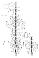
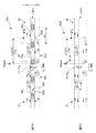
図1は、吸収性物品1の製造ライン20を側面視で示す模式図である。この製造ライン20では、排泄液を吸収する吸収性物品1の一例として使い捨ておむつ1を製造する。
=== This Embodiment ===
<<< Schematic configuration of
FIG. 1 is a schematic diagram showing a
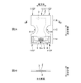
図2Aは、このおむつ1の一例の平面図であり、図2Bは、図2A中のB−B断面図である。
おむつ1は、例えば、不織布等の液透過性のトップシート2とフィルム等の液不透過性のバックシート4との間に、パルプ繊維を主原料とする吸収体3が介装されたものを本体11とする。
そして、その展開状態の平面形状は、略砂時計形状になっている。つまり、おむつ1の長手方向の両端部たる腹側部11Aや背側部11Bの幅は、それらの間の部位たる股下部11Cの幅よりも広くなっている。これにより、腹側部11Aや背側部11Bにおける幅方向の両端部にはサイドフラップ11SF,11SF…が形成されている。
また、背側部11Bには、一対の面ファスナー5,5を有したファスニングテープ部材6が貼り付けられている。そして、おむつ1の使用時には、例えば同部材6における幅方向の中央部のミシン目6mを分断することにより、一対の面ファスナー5,5をおむつ1の幅方向に開くように構成されており、これにより、おむつ1の装着時の背側部11Bの腹側部11Aへの止着に供するようになっている。
なお、股下部11C近傍の脚周り開口部11H,11Hをなす部位に伸縮性を付与すべく、おむつ1の幅方向の両側の部分に不図示の糸ゴム等の弾性部材を長手方向に沿って設けても良いし、同幅方向の両側の部分に、それぞれ立体ギャザー(不図示)を設けても良い。
FIG. 2A is a plan view of an example of the
The
And the planar shape of the unfolded state is a substantially hourglass shape. That is, the width of the
A
In addition, elastic members such as rubber thread (not shown) are provided along the longitudinal direction on both side portions in the width direction of the
図1に示すように、おむつ1の製造ライン20は、おむつ1の半製品1a,1b…等を搬送方向に搬送する複数の搬送機構22,22…を有する。各搬送機構22,22…には、載置面たる無端ベルトの表面に吸引機能を有したサクションベルトコンベア22が使用され、それぞれ、不図示のモータ等を駆動源として無端ベルトが周回駆動する。なお、場合によっては搬送ローラーを用いても良い。
そして、かかる搬送機構22,22…によって半製品1a,1b…等を搬送方向に搬送中に、当該半製品1a,1b…等に対して他の部品の接着や、折り畳み、切断等の各種加工等を順次行って、おむつ1が完成される。
As shown in FIG. 1, the
While the
なお、以下の説明では、おむつ1の搬送方向と直交する方向(図1中では、その紙面を貫通する方向)のことを「CD方向」とも言う。また、搬送方向の下流側及び上流側のことを、それぞれ前方及び後方とも言う。 In the following description, a direction perpendicular to the conveyance direction of the diaper 1 (in FIG. 1, a direction penetrating the paper surface) is also referred to as a “CD direction”. Further, the downstream side and the upstream side in the transport direction are also referred to as the front and the rear, respectively.
図1に示すように、製造ライン20は、複数のリール25,25を有する。リール25は、例えば、トップシート2及びバックシート4のそれぞれに対して設置されている。どちらのシート2,4についても、製造ライン20への搬入は、シートを巻き取ってなるシートロールの形態でなされる。そして、各シートロール2r,4rは、それぞれ、対応するリール25に装着されて連続シートの形態で繰り出される。また、同製造ライン20は、主な加工装置として、積繊装置30やロータリーダイカッター装置40、ロータリーカッター装置50等を有し、また、搬送方向の下流側には、おむつ1の不良品を製造ライン20から排出する不良品排出装置60を有している。
As shown in FIG. 1, the
積繊装置30は、吸収体3の主原料となるパルプ繊維を略直方体等の所定形状に成形して吸収体3を生成し、生成された吸収体3を搬送方向に製品ピッチP1でサクションベルトコンベア22上に載置する。
The
その下流には、バックシート4の合流位置G4が設定されている。すなわち、同位置G4では、バックシート4が下方から連続シートの形態で供給され、当該バックシート4の上面に吸収体3を製品ピッチP1で載せる。
A merging position G4 of the
また、同合流位置G4の近傍には、トップシート2の合流位置G2が設定されている。よって、同位置G2では、バックシート4上に吸収体3が載った状態の半製品1aに対して、その上方からトップシート2が連続シートの形態で供給され、吸収体3を上方から覆うようにしつつ当該シート2がバックシート4に貼り合わされる。これにより半製品1aは半製品1bとなる。
Moreover, the merge position G2 of the
その下流の位置では、半製品1bが具備するトップシート2に対して、不図示の受け渡し装置により、単票状のファスニングテープ部材6(不図示)が製品ピッチP1で貼り付けられ、これにより半製品1bは半製品1cとなる。
At a downstream position, a single-sheet fastening tape member 6 (not shown) is attached to the
その下流には、ロータリーダイカッター装置40が配されている。この装置40は、互いに対向して駆動回転するカッターロール41とアンビルロール42とを有する。そして、これらロール41,42の間隙を半製品1cが通過する際に、これらロール41,42は、製品ピッチP1で半製品1cのCD方向の両端縁を略半円状に切り欠き、これにより、半製品1cを前述の略砂時計形状の半製品1dに成形する。
A rotary
そうしたら、半製品1dは、不図示の折り畳み機構に通される。ここでは、前述の略半円形状の切り欠き処理によりCD方向の両側に形成された各サイドフラップ11SF,11SFを、それぞれCD方向の内方に折り畳む。これにより半製品1dは半製品1eとなる。そして、当該半製品1eは、次のロータリーカッター装置50へ送られる。
Then, the
ロータリーカッター装置50も、互いに対向して駆動回転するカッターロール51とアンビルロール52とを有する。そして、これらロール51,52の間隙を半製品1eが通過する際に、これらロール51,52は、当該半製品1eを製品ピッチP1で分断し、これにより、製品単位で個別に分かれた状態のおむつ1が完成する。
The
そうしたら、各おむつ1は、不良品排出装置60(不良ワーク排出装置に相当)へ送られる。ここでは、搬送中に各おむつ1が良品と不良品とに振り分けられ、良品は、そのまま搬送路81tを通って下工程へ送られるが(図1中の下段の図を参照)、不良品は排出路100tを介して製造ライン20から排出される(図1中の上段の図を参照)。なお、この分別は、コントローラ110が、製造ライン20の搬送路の適宜位置に配された各種センサー92,94,96,97,98からの信号に基づいて行う。これについては後述する。
Then, each
<<<不良品について>>>
上述の製造ライン20は、連続生産を前提として稼働している。よって、基本的に製造に必要な各資材は、常に途切れないように連続供給される。例えば、図3Aに示すように、トップシート2やバックシート4の各シートロール2r,4rに対しては、それぞれ、リール25,25が一対ずつ準備されており、一方のリール25が繰り出し供給中の場合には、他方のリール25は待機中になっている。そして、繰り出し供給中のリール25からのシート2(4)の繰り出し終了時には、図3Bに示すように、待機中のシートロール2r(4r)の繰り出し先端2LE(4LE)が、先行材たる繰り出し供給中のシート2(4)の尾端2TE(4TE)に継がれる。例えば、粘着テープやホットメルト接着剤又はヒートシール等により接合される。そして、これにより、資材の連続供給が行われる。
<<< About defective products >>>
The
但し、上述の先端2LE(4LE)と尾端2TE(4TE)との接合部たる継ぎ目部2j(4j)は、当然ながら非定常部であり、この部分2j(4j)を含んだおむつ1(以下、製品1とも言う)は不良品となる。
また、ファスニングテープ部材6等の部品を半製品1bに貼り合わせる際に、貼り合わせ位置の許容範囲からずれて貼り合わせられた場合についても、その製品1は不良品となる。
よって、かかる不良品については、不良品排出装置60によって製造ライン20外に排出するようにしている。
However, the
Further, when a component such as the
Therefore, such defective products are discharged out of the
なお、上述の継ぎ目部2j(4j)のような不良部を検知して、個別の複数のおむつ1,1…の中から不良品を特定するためのセンサー92,94,96は、不良の種類毎に設けられ、各センサー92,94,96からの不良部検知信号は、それぞれ、後述のコントローラ110に送信されて、不良品の排出に供される。
The
<<<不良品排出装置60>>>
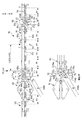
図4は不良品排出装置60の概略側面図である。
不良品排出装置60は、半製品1eを製品単位に分断しておむつ1を生成するロータリーカッター装置50(分断機構に相当)の下流側に近接配置されている。そして、分断生成されたおむつ1(ワークに相当)は、そのままロータリーカッター装置50のロール51,52の駆動回転によって不良品排出装置60の搬送路61tへと連続的に送り込まれる。
<<< Defective
FIG. 4 is a schematic side view of the defective
The defective
この不良品排出装置60は、ロータリーカッター装置50の下流側に配置され、第1搬送路61tを形成する第1コンベア61と、この第1コンベア61の下流側に配置され、第2搬送路81tを形成する第2コンベア81と、これら第1コンベア61と第2コンベア81との間に配されて、揺動動作により搬送路71tを第2搬送路81t及び排出路100tのどちらに択一的に接続する振り分けコンベア71(振り分け機構に相当)と、不良品を検知するセンサー92,94,96,97や第1コンベア61の状態を検出するセンサー98等のセンサー群(図1)と、センサー群から出力される各種信号に基づいて、振り分けコンベア71を制御するコントローラ110(図1)と、を有する。
The defective
以下、不良品排出装置60の各構成要素について説明するが、以下の説明では、特に断らない限り、その説明で登場する何れのローラー63u,63d,73u,73d,83u,83dの回転軸もCD方向を向いているものとする。
Hereinafter, each component of the defective
第1コンベア61は、上下一対の無端ベルト62u,62dを有する。下無端ベルト62dは、搬送方向の前後一対のローラー63d,63dに掛け回されている。そして、これらローラー63d,63dのうちの少なくとも一方のローラー63dは、駆動源としてのモータ(不図示)から駆動回転力が付与されて駆動回転し、これにより下無端ベルト62dは周回する。また、下無端ベルト62dは、表面に複数の吸気孔(不図示)を有し、これにより表面に載置したおむつ1を吸引して保持する。
The
一方、上無端ベルト62uは、搬送方向の前後一対のローラー63u,63uに掛け回されている。そして、上無端ベルト62uは、下無端ベルト62dとの間におむつ1を挟んで搬送すべく、所定の押し付け力で下無端ベルト62dに押圧されている。これにより、これら上無端ベルト62uと下無端ベルト62dとの間に形成された前記第1搬送路61tを、これら無端ベルト62u,62dと略一体となっておむつ1は移動する。そして、第1搬送路61tの下流端61eで振り分けコンベア71におむつ1を引き渡す。
On the other hand, the upper
ちなみに、上無端ベルト62uにあっては、下無端ベルト62dから駆動力を得て従動周回する従動ベルトとして構成しても良いし、上述のモータから適宜な歯車伝達機構等により駆動力が伝達されて駆動周回する駆動ベルトとして構成しても良い。なお、後者の駆動周回の場合には、上無端ベルト62uは、下無端ベルト62dと同期して周回動作をするのは言うまでも無い。
Incidentally, the upper
ここで、この第1コンベア61の搬送速度V61は、ロータリーカッター装置50のカッターロール51の周速V50、すなわちロータリーカッター装置50での半製品1eの搬送速度V50よりも速い速度で、且つ、この搬送速度V50に連動して(比例して)変化するようにコントローラ110により制御される。つまり、ロータリーカッター装置50の搬送速度V50よりも所定倍率Rmだけ増速されている(V61=Rm×V50)。これにより、ロータリーカッター装置50によって分断生成されたおむつ1は、第1コンベア61に乗り移った際に、第1コンベア61に引き取られるように搬送され、結果、搬送方向の上流側に隣り合うおむつ1との間には間隔δが形成される。つまり、第1コンベア61よりも下流側の搬送ピッチP2は、製品ピッチP1の前記所定倍率Rmだけ拡大されたピッチP2(=Rm×P1=P1+δ)となっている。
Here, the conveyance speed V61 of the
そして、この第1コンベア61の搬送速度V61は、振り分けコンベア71や第2コンベア81でも維持される。よって、上記の拡大された搬送ピッチP2は、少なくとも第1コンベア61から第2コンベア81までの範囲において維持される。
The transport speed V61 of the
ちなみに、この拡大された搬送ピッチP2は、振り分けコンベア71の搬送路71tの全長L71t以上の長さに設定されていると良い。これにより、振り分けコンベア71の揺動動作によって排出対象のおむつ1を排出する際に、当該排出対象のおむつ1の前又は後に隣り合うおむつ1に何等影響を与えること無く、当該排出対象のおむつ1のみを選択的に排出路100tへ誘導可能となる。
Incidentally, the enlarged transport pitch P2 may be set to a length equal to or longer than the total length L71t of the transport path 71t of the sorting
第2コンベア81も、上下一対の無端ベルト82u,82dを有する。下無端ベルト82dは、搬送方向の前後一対のローラー83d,83dに掛け回されている。そして、これらローラー83d,83dのうちの少なくとも一方のローラー83dは、駆動源としての不図示のモータから駆動回転力が付与されて駆動回転し、これにより下無端ベルト82dは周回する。また、下無端ベルト82dは、表面に複数の吸気孔(不図示)を有し、これにより表面に載置したおむつ1を吸引して保持する。
The
一方、上無端ベルト82uは、搬送方向の前後一対のローラー83u,83uに掛け回されている。そして、上無端ベルト82uは、下無端ベルト82dとの間におむつ1を挟んで搬送すべく、所定の押し付け力で下無端ベルト82dに押圧されている。これにより、これら上無端ベルト82uと下無端ベルト82dとの間に形成された第2搬送路81tを、これら無端ベルト82u,82dと略一体となっておむつ1は移動する。そして、第2搬送路81tの下流端81eで、下工程の適宜なコンベア150に良品のおむつ1を引き渡す。
ちなみに、上無端ベルト82uを、従動ベルト及び駆動ベルトのどちらで構成しても良いのは、上述の第1コンベア61の場合と同じである。
On the other hand, the upper
Incidentally, the upper
振り分けコンベア71も、上下一対の無端ベルト72u,72dを有する。下無端ベルト72dは、搬送方向の前後一対のローラー73d,73dに掛け回されている。そして、これらローラー73d,73dのうちの少なくとも一方のローラー73dは、駆動源としての不図示のモータから駆動回転力が付与されて駆動回転し、これにより下無端ベルト72dは周回する。また、下無端ベルト72dは、表面に複数の吸気孔(不図示)を有し、これにより表面に載置したおむつ1を吸引して保持する。
The sorting
一方、上無端ベルト72uは、搬送方向の前後一対のローラー73u,73uに掛け回されている。そして、上無端ベルト72uは、下無端ベルト72dとの間におむつ1を挟んで搬送すべく、所定の押し付け力で下無端ベルト72dに押圧されている。これにより、これら上無端ベルト72uと下無端ベルト72dとの間に形成された搬送路71tを、これら無端ベルト72u,72dと略一体となっておむつ1は移動する。そして、搬送路71tの下流端71eで第2コンベア81又は排出路100tにおむつ1を引き渡す。
On the other hand, the upper endless belt 72u is wound around a pair of front and
なお、上無端ベルト72uを、従動ベルト及び駆動ベルトのどちらで構成しても良いのは、上述の第1コンベア61の場合と同じである。
Note that the upper endless belt 72u may be formed of either a driven belt or a driving belt, as in the case of the
ここで、図4中の下段の図に示すように、当該振り分けコンベア71に係る上無端ベルト72u及び下無端ベルト72dは、それぞれ、上流側のローラー73u,73dの回転軸C73u,C73dを揺動中心として、下流側の端部たるローラー73u,73dが上下方向に揺動可能に構成されている。また、この揺動動作の駆動機構として、ピストンを伸縮動作する油圧シリンダー75,75が上無端ベルト72u及び下無端ベルト72dのそれぞれについて設けられており、更には、油圧シリンダー75,75の伸縮動作を切り替える作動制御部75s,75sとしての電磁弁等もそれぞれ設けられている。
Here, as shown in the lower diagram of FIG. 4, the upper endless belt 72u and the lower
そして、これら油圧シリンダー75,75の伸縮動作により、振り分けコンベア71の搬送路71tは、当該搬送路71tにおける第1コンベア61側の端部71e1を支点として、同第2コンベア81側の端部71e2を上下方向に揺動可能に構成されている。よって、同搬送路71tを、第2コンベア81の第2搬送路81t及びその下方の排出路100tの何れかに択一的に接続することにより、排出対象のおむつ1を排出路100tへ排出可能である。すなわち、排出されるべきおむつ1が第1コンベア61の第1搬送路61tから送られてきた場合には、振り分けコンベア71の搬送路71tは、排出路100tへ接続されるが、それ以外の場合には、同搬送路71tは第2コンベア81の第2搬送路81tに接続される。これにより、排出されるべきおむつ1を選択的に製造ライン20から排出する。
Then, due to the expansion and contraction of these
センサー群は、図1に示すように、不良部を検知する不良部検知センサー92,94,96と、第1コンベア61上に設けられ、おむつ1の通過を検知する通過検知センサー97と、第1コンベア61の搬送状態を監視する状態監視センサー98と、を有する。
As shown in FIG. 1, the sensor group includes defective
不良部検知センサー92,94,96は、前述したように、想定される不良部の種類毎に設けられる。例えば、本実施形態では、不良部として、トップシート2の継ぎ目部2jやバックシート4の継ぎ目部4j、貼り付け位置が許容範囲から外れたファスニングテープ部材6等を想定している。
As described above, the defective
そのため、図1の製造ライン20には、トップシート2用の継ぎ目部検知センサー92が、例えばリール25の繰り出し位置と前述の合流位置G2との間に配置され、また、バックシート4用の継ぎ目部検知センサー94が、例えばリール25の繰り出し位置と前述の合流位置G4との間に配置されている。そして、これらセンサー92,94は、所定の検知位置92p,94pを継ぎ目部2j,4jが通過する度に継ぎ目部2j,4jを検知して不良部検知信号をコントローラ110へ出力する。なお、かかるセンサー92,94の一例としては、受けた光量に応じた大きさの信号を出力する光電管等が挙げられる。
Therefore, in the
また、ファスニングテープ部材6の貼り付け位置不良を検知するセンサー96も、ファスニングテープ部材6の半製品1dへの受け渡し位置の直近下流側の位置に設置されている。このセンサー96は、例えば赤外線カメラである。そして、例えばロータリーカッター装置50のロータリーエンコーダ54からの同期信号に基づいて当該カメラは作動し、これにより、半製品1eを製品ピッチP1毎に撮影して製品1に相当する単位で温度分布の画像を取得する。そして、その画像を二値化処理等して、実際の貼り付け位置を各製品1(正確には、各製品1となり得る部分)の輪郭位置基準で特定し、特定された貼り付け位置が、前記輪郭位置から定まる規定の貼り付け目標位置の許容範囲内に収まっているか否かを判定する。そして、許容範囲に収まっていない場合には、その都度、不良部検知信号をコントローラ110へ出力する。ちなみに、二値化処理や上述の判定を行う構成については、コントローラ110側に設けても良い。
In addition, a
通過検知センサー97は、第1コンベア61に配置されている。そして、おむつ1の通過を検知する検知位置97pも、第1搬送路61t上に設定されている。よって、当該検知位置97pをおむつ1の下流端が通過する度に、通過検知センサー97は、通過検知信号をコントローラ110へ出力する。これについては後述する。
The
状態監視センサー98は、例えば第1コンベア61のローラー63dに設けられたロータリーエンコーダ98である(図1)。そして、このエンコーダ98は、第1コンベア61のローラー63dの回転角度(回転量)を計測し、回転角度に比例した値のデジタル値の信号、又は回転角度に比例した数のパルスの信号をコントローラ110へ出力する。
The
コントローラ110は、適宜なPLC(プログラマブルロジックコントローラ)等のコンピュータであり、上記の各センサー92,94,96,97,98等から出力される信号に基づいて、振り分けコンベア71の揺動動作を制御する。つまり、振り分けコンベア71の駆動機構たる前記油圧シリンダー75,75を制御する。
The
<<<振り分けコンベア71の排出動作(振り分け動作)>>>
ここで、振り分けコンベア71の排出動作について詳細に説明する。なお、以下では、トップシート2の継ぎ目部2jを有するおむつ1を不良品として排出する場合を例に説明するが、バックシート4の継ぎ目部4jや貼り付け位置不良の場合も同様である。
<<< Discharge operation (sorting operation) of sorting
Here, the discharging operation of the sorting
先ず、この排出処理ロジックの基本的な考え方について説明する。
図1の継ぎ目部検知センサー92の検知位置92pから第1コンベア61上の通過検知センサー97の検知位置97pまでの搬送路に、製品たるおむつ1となり得る部分が何個含まれているかの想定数は、設計図や実際の設備配置等に基づいて予めわかる既知の値である。よって、継ぎ目部検知センサー92が継ぎ目部2jを検知した時点を起点として、以降、第1搬送路61tの通過検知センサー97の通過検知信号に基づいて、通過検知センサー97の検知位置97pを通過したおむつ1の個数をカウントすれば、継ぎ目部2jを有するおむつ1たる不良品が、通過検知センサー97の検知位置97pに到達する到達時点を認識することができる。そうしたら、この到達時点を零値(起点)とする所定量の搬送後に、振り分けコンベア71を下方に揺動して排出路100tに接続すれば、不良品1を排出することができる。
よって、かかる排出処理ロジックに基づけば、通過検知センサー97の検知位置97pを、可能な限り振り分けコンベア71に近接化するのが、排出精度の観点からは好ましいと考えられる。
First, the basic concept of the discharge processing logic will be described.
Assumed number of parts that can be the
Therefore, based on such discharge processing logic, it is considered preferable from the viewpoint of discharge accuracy to make the
一方、フェールセーフ的に不良品1の排出ミスを防ぐ観点からは、当該不良品1だけでなく、その搬送方向の前後に隣り合うおむつ1も含めて(つまり巻き込んで)排出することが考えられる。但し、その場合には、上述のように通過検知センサー97を振り分けコンベア71に近接化し過ぎると、図5のように、振り分けコンベア71を下方に揺動動作させて排出路100tに接続した時点には、不良品1の下流側の隣のおむつ1は既に振り分けコンベア71を通過し終わって第2コンベア81上を走行している虞があって、つまり、当該隣のおむつ1を製造ライン20外に排出できない可能性がある。
On the other hand, from the viewpoint of fail-safe prevention of
そこで、本実施形態では、図4に示すように、通過検知センサー97がおむつ1の通過を検知する検知位置97pを、第1搬送路61tの下流側の端61ted(振り分け機構側の端に相当)から、少なくとも搬送ピッチP2の長さ以上だけ上流側に離れた位置に設定している。そして、このようにすれば、当該検知位置97pを不良品1の下流端が通過した際には、その下流に隣り合うおむつ1も未だ第1搬送路61t上に在るはずである。よって、不良品1の下流側に少なくとも一つのおむつ1を巻き込みながら当該不良品1を排出路100tへ排出可能となる。
Therefore, in the present embodiment, as shown in FIG. 4, the
ちなみに、下流側において巻き込んで排出するおむつ1の個数を複数にする場合、例えばN個(Nは2以上の整数)にする場合には、上述の検知位置97pを、搬送ピッチP2のN倍の長さ以上だけ第1搬送路61tの下流側の端61tedから離れた位置に設定すると良い。そうすれば、上述と同じ理屈で、不良品1の下流側に位置するN個のおむつ1を確実に巻き込んで不良品1を排出可能となり、不良品1の排出確度をより一層高めることができる。
更には、不良品1の上流側においても、同数のN個だけおむつ1を巻き込んで排出すれば、より排出ミスの可能性は低くなる。
従って、本実施形態では、不良品1の両側の巻き込み数を、それぞれN個に設定している。すなわち、不良品1の上流側において巻き込んで排出するおむつ1の数をN個にし、また、同様に、同不良品1の下流側において巻き込んで排出するおむつ1の数もN個にしている。そのため、通過検知センサー97の検知位置97pは、第1搬送路61tの下流側の端61tedから、下式1を満足する距離Lだけ離れた位置に設定されている。
L≧N×P2 … (1)
By the way, when the number of
Furthermore, even on the upstream side of the
Therefore, in this embodiment, the number of entanglements on both sides of the
L ≧ N × P2 (1)
図6は、コントローラ110の排出処理部が実行する排出処理のフロー図である。排出処理部は例えばプログラムで構成される。つまり、コントローラ110のプロセッサが、メモリ等から排出処理プログラムを読み出して実行することにより、排出処理が行われる。よって、以下の説明では、排出処理部が排出処理を行っているかのように記載しているが、実際には、同処理はプロセッサにより行われる。
FIG. 6 is a flowchart of the discharge process executed by the discharge processing unit of the
先ず、図1のトップシート用継ぎ目部検知センサー92が、トップシート2の継ぎ目部2jの通過を検知すると、同検知センサー92は、コントローラ110の排出処理部へ不良部検知信号を出力する(S10)。
First, when the top sheet
すると、これを受信した排出処理部は、自身が具備するカウンタを作動する。すなわち、この受信時点のカウンタのカウント値を零値として、以降、第1搬送路61tの通過検知センサー97から通過検知信号を受信する度に、カウント値に「1」を加算していく(S20)。そして、逐次、当該カウント値を、既定の閾値Kthと大小比較する(S30)。
なお、この閾値Kthは、前述のおむつ1の想定数であり、コントローラ110内のメモリに予め記憶されている。すなわち、この閾値Kthは、継ぎ目部検知センサー92の検知位置92pと通過検知センサー97の検知位置97pとの間の搬送路に存在するおむつ1の個数(正確には、おむつ1となり得る部分の個数)を示しており、例えば、下式2で表される。
Kth=D1/P1+D2/P2 … (2)
ここで、上式2中のD1は、継ぎ目部検知センサー92の検知位置92pからロータリーカッター装置50の装置中心までの搬送路の経路長である。また、同D2は、ロータリーカッター装置50の前記装置中心から通過検知センサー97の検知位置97pまでの搬送路の経路長である。
Then, the discharge processing unit that has received this operates a counter included in itself. That is, the count value of the counter at the time of reception is set to zero, and thereafter, every time a passage detection signal is received from the
The threshold value Kth is the assumed number of
Kth = D1 / P1 + D2 / P2 (2)
Here, D1 in the
ちなみに、上式2の右辺において、継ぎ目部検知センサー92の検知位置92pから通過検知センサー97の検知位置97pまでの経路長を二つの経路長D1,D2に分けて計算している理由は、ロータリーカッター装置50を境として、おむつ一つ当たりの搬送ピッチが製品ピッチP1から搬送ピッチP2(>P1)に変化するためである(図4を参照)。
Incidentally, the reason why the path length from the detection position 92p of the
また、望ましくは、式2中のD1/P1の値とD2/P2の値とのそれぞれが、整数値の±5%の範囲に収まるように各センサー92,97の検知位置92p,97pを調節すると良く、より望ましくは整数値になるように調整すると良い。このようにすれば、不良品1が通過検知センサー97の検知位置97pに到達する時点をより正確に認識可能となる。
Desirably, the detection positions 92p and 97p of the
そして、上記大小比較のステップS30においてカウンタ値が前記閾値Kthを超えたら、排出処理部は、当該超えた時点に、継ぎ目部2jを有するおむつ1の先端(下流端)が通過検知センサー97の検知位置97pに到達したと判定する。
When the counter value exceeds the threshold value Kth in the size comparison step S30, the discharge processing unit detects that the tip (downstream end) of the
そうしたら、排出処理部は、この超えた時点(到達時点)を零値として、以降の第1コンベア61の搬送量を、同第1コンベア61のエンコーダ98の信号に基づいて計測する(S40)。そして、逐次、この搬送量の値を既定の閾値Tthと大小比較する(S50)。
If it does so, a discharge processing part will measure the amount of conveyance of the
ここで、この閾値Tthも、コントローラ110内のメモリに予め記憶されている。そして、この閾値Tthというのは、継ぎ目部2jを有するおむつ1たる不良品1が通過検知センサー97の検知位置97pを通過(到達)した時点において、この不良品1よりもN個だけ下流側のおむつ1の位置が、第1搬送路61tの下流側の端61tedからどれだけ離れているかという距離を示しており、これは、既述のL、N、P2を用いて、下式3で表される。
Tth=L−N×P2 … (3)
よって、上記大小比較のステップS50において、当該閾値Tthを前記搬送量の値が超えたら、排出処理部は、不良品1と伴に排出すべきN個分下流側に位置するおむつ1が、第1搬送路61tの下流側の端61tedに到達したと判定する。
Here, this threshold value Tth is also stored in advance in the memory in the
Tth = L−N × P2 (3)
Therefore, when the value of the transport amount exceeds the threshold value Tth in the size comparison step S50, the discharge processing unit determines that the
そうしたら、その時点に、排出処理部は、振り分けコンベア71の電磁弁等の作動制御部75sに排出信号を送信し、これを受信した作動制御部75sは油圧シリンダー75,75を制御して、振り分けコンベア71の搬送路71tの接続先を、第2搬送路81tから排出路100tへと切り替える(S60)。
Then, at that time, the discharge processing unit transmits a discharge signal to the operation control unit 75 s such as the electromagnetic valve of the sorting
なお、この排出信号の送信(出力)は、不良品1よりもN個だけ上流側のおむつ1が排出路100tから排出されるまで継続され、また、この排出信号を受信している間に亘って、作動制御部75sは、振り分けコンベア71の搬送路71tの接続先を排出路100tにした状態に維持する。これにより、継ぎ目部2jを有するおむつ1たる不良品1を含めその前後に各N個のおむつ1が排出路100t経由で排出される。
The transmission (output) of the discharge signal is continued until
ちなみに、排出処理部は、排出信号の送信の停止を、例えば前述のカウンタ値を用いて行う。すなわち、カウンタ値が下式4の第2閾値Kth2を超えたら排出信号の送信を停止する(S70、S80)。
Kth2=Kth1+(L71t+L)/P2+N … (4)
そして、これにより、不良品1よりも上流側のN個のおむつ1を排出し終えたところで、振り分けコンベア71の接続先が再度第2搬送路81tに戻されて、以降搬送されるおむつ1は良品として第2搬送路81tを経て製造ライン20の下工程へと送られる。なお、当該第2閾値Kth2も、コントローラ110内のメモリに予め記憶されている。
Incidentally, the discharge processing unit stops the transmission of the discharge signal using, for example, the counter value described above. That is, when the counter value exceeds the second threshold value Kth2 of the following
Kth2 = Kth1 + (L71t + L) / P2 + N (4)
As a result, when the
ところで、前述したように、継ぎ目部検知センサー92の如き不良部検知センサーは、不良の種類毎に設けられている。よって、不良部検知信号もその不良の種類の数だけ出力される。そのため、かかる複数種類の不良部検知信号に対処すべく、コントローラ110は、上述の排出処理部たる排出処理プログラムを、センサー92,94,96毎に対応させてそれぞれ有している。そして、コントローラ110のプロセッサは、各排出処理プログラムを並列処理する。これにより、各排出処理部から、それぞれ、振り分けコンベア71の作動制御部75sへ向けて排出信号が送信(出力)されることになる。
Incidentally, as described above, a defective portion detection sensor such as the joint
ここで、振り分けコンベア71の作動制御部75sは、何れか一つの排出信号を受信している限り、その搬送路71tを排出路100tに接続するように、振り分けコンベア71の油圧シリンダー75,75を制御する。つまり、排出信号を一つも受信しない状態になったら、作動制御部75sは、振り分けコンベア71の搬送路71tを第2搬送路81tへ接続するように油圧シリンダー75,75を制御する。
これにより、互いに種類の異なる不良部を有するおむつ1,1同士が近接して搬送されている場合でも、円滑に振り分け動作を行うことができ、また、不良部を全く有しないおむつ1のみを第2搬送路81t経由で下工程へ送ることもできるようになる。
Here, as long as the operation control part 75s of the
Thereby, even when the
なお、望ましくは、トップシート用継ぎ目部検知センサー92やバックシート用継ぎ目部検知センサー94等に対しては、次のような機能を有したセンサーを用いると良い。すなわち、連続シート状部材としてのトップシート2やバックシート4において前後に隣り合うおむつ1,1同士(正確には、おむつ1に相当する部分同士)に継ぎ目部2j(4j)が跨っているか否かを検知可能なセンサーを用いると良い。
Desirably, a sensor having the following function may be used for the top sheet
そして、当該センサー92(94)から送信された不良部検知信号に基づいて、排出処理部が「継ぎ目部2j(4j)は跨っておらず一つのおむつ1(正確には、おむつ1となりうる部分)内に収まっている」と判定した場合には、排出処理部は、上述と同様の排出処理を行う。
Then, based on the defective part detection signal transmitted from the sensor 92 (94), the discharge processing part is “a
一方、「継ぎ目部2j(4j)は跨っている」と判定した場合には、排出処理部は、排出信号の作動制御部75sへの送信開始のタイミングを、跨ったおむつ1,1同士のうちの下流側のおむつ1に基づいて決める一方、排出信号の送信停止のタイミングを、同跨ったおむつ1,1同士のうちの上流側のおむつ1に基づいて決める。その結果、送信開始のタイミングについては、跨っていない場合と同じタイミングとなるが、送信停止のタイミングについては、跨っていない場合と比べて、おむつ一つ分だけ延長されることになる。すなわち、継ぎ目部2j(4j)が跨らない場合(つまり一つのおむつ1内に継ぎ目部2j(4j)が完全に収まる場合)と比較して、継ぎ目部2j(4j)が跨った場合には、排出するおむつ1の数が一つだけ増えることになる。そして、これにより、継ぎ目部2j(4j)を有するおむつ1の排出ミスをより確実に防ぐことができる。
On the other hand, when it is determined that “the
このような継ぎ目部2j(4j)が跨っているか否かを検知可能なセンサーの一例としては、前述した赤外線カメラが挙げられる。詳しくは、このカメラは、ロータリーカッター装置50のエンコーダ54からの同期信号に基づいて作動し、これにより、トップシート2やバックシート4を製品ピッチP1で撮影して製品1に相当する単位で温度分布の画像を取得する。そして、撮影の都度、即座に、取得した画像を排出処理部へ送信する。すると、排出処理部では、その画像を二値化処理等して、継ぎ目部2j(4j)の位置を各製品1(正確には、各製品1となり得る部分)の輪郭位置基準で特定し、特定された継ぎ目部2j(4j)の位置が、前記輪郭位置に重なっているか否かを判定する。そして、重なっている場合には、「継ぎ目部2j(4j)は跨っている」と判定し、重なっていない場合には「継ぎ目部2j(4j)は跨っていない」と判定する。
As an example of a sensor capable of detecting whether or not such a
===その他の実施の形態===
以上、本発明の実施形態について説明したが、本発明は、かかる実施形態に限定されるものではなく、以下に示すような変形が可能である。
=== Other Embodiments ===
As mentioned above, although embodiment of this invention was described, this invention is not limited to this embodiment, The deformation | transformation as shown below is possible.
前述の実施形態では、不良品排出装置60として、一部のコンベア71が揺動動作をするものを例示したが、何等これに限るものではない。
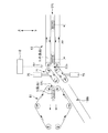
例えば、不良品排出装置60aを、図7Aのように構成しても良い。すなわち、第1搬送路61tを形成する第1コンベア61における下流側の端部61eについては、下無端ベルト62dのみが下流側に突出して位置するように第1コンベア61を構成し、また、第2搬送路81tを形成する第2コンベア81における上流側の端部81eについても、下無端ベルト82dのみが上流側に突出して位置するように第2コンベア81を構成する。また、これら端部61e,81e同士の間には間隔Δを設け、当該間隔Δを跨って、その上方には、振り分け機構71aの一部をなす無端ベルト72aを配置する。そして、この無端ベルト72aをサクションベルトコンベアとして構成し、これにより、第1搬送路61tを通過したおむつ1を、無端ベルト72aの表面で吸着して受け取り、当該吸着によりおむつ1を吊り下げ保持状態で搬送して第2搬送路81tに引き渡すようにする。
In the above-described embodiment, as the defective
For example, the defective
更に、この無端ベルト72aには、吊り下げ保持状態で搬送されるおむつ1を無端ベルト72aの表面から剥がし落とすための剥がし落とし機構77を設ける。これにより、排出されるべきおむつ1が、この剥がし落とし機構77の位置を通過する際に、この機構77を作動させれば、おむつ1は無端ベルト72aから剥がれ落ちて、上述の間隔Δを排出路100tとして排出され、他方、作動させなければ、おむつ1はそのまま第2搬送路81tへ引き渡される。
Further, the
このような剥がし落とし機構77としては、適宜なエアー源を制御することにより、下方に向けて空気を噴射/停止可能なエアブロー機構77a(図7A)や、油圧シリンダー等の適宜なアクチュエータを制御することにより、棒状部材77bを下方に出没可能なプッシャー機構77c(図7B)等が挙げられる。 As such a peel-off mechanism 77, an appropriate air source is controlled to control an air blow mechanism 77a (FIG. 7A) capable of injecting / stopping air downward and an appropriate actuator such as a hydraulic cylinder. As a result, a pusher mechanism 77c (FIG. 7B) that can protrude and retract the bar-like member 77b downward is exemplified.
そして、かかる構成の不良品排出装置60aにおいても、本発明に係る概念を適用可能である。すなわち、図7A及び図7Bの第1搬送路61tの下流側の端61tedから搬送ピッチP2以上離れた位置に、通過検知センサー97の検知位置97pを設定する。そうすれば、不良部を有するおむつ1の直前のおむつ1も巻き込んで排出可能となる。
The concept according to the present invention can also be applied to the defective
前述の実施形態では、式2及び式4に基づいて予め閾値Kth及び第2閾値Kth2を算出しておき、これら閾値Kth,Kth2をコントローラ110のメモリに記憶させていたが、何等これに限るものではない。例えば、コントローラ110の排出処理部が、図6の排出処理を実行する度に、式2及び式4の演算を行ってこれら閾値Kth,Kth2を求めても良い。
In the above-described embodiment, the threshold value Kth and the second threshold value Kth2 are calculated in advance based on the
前述の実施形態では、式3に基づいて予め閾値Tthを算出しておき、これら閾値Tthをコントローラ110のメモリに記憶させていたが、何等これに限るものではない。例えば、コントローラ110の排出処理部が、図6の排出処理を実行する度に、式3の演算を行って閾値Tthを求めても良い。
In the above-described embodiment, the threshold values Tth are calculated in advance based on
前述の実施形態では、図6の排出処理のステップS50に係る閾値Tthを距離で規定し、同ステップS50では、この閾値Tthと第1コンベア61の搬送量とを大小比較していたが、何等これに限るものではない。例えば、閾値Tthの値を、第1コンベア61のローラー63dの直径の円周率倍の値で除算することにより、閾値Tthに相応する回転角度の閾値Φthを求めるとともに、排出処理のステップS50では、当該閾値Φthと、第1コンベア61のエンコーダ98が出力する回転角度Φとを大小比較して、排出信号の出力タイミング(送信開始のタイミング)を制御しても良い。
In the above-described embodiment, the threshold value Tth related to step S50 of the discharge process of FIG. 6 is defined by the distance. In this step S50, the threshold value Tth and the transport amount of the
前述の実施形態では、不良部の種類として、トップシート2の継ぎ目部2jやバックシート4の継ぎ目部4j等を例示したが、何等これに限るものではない。例えば、積繊装置30において吸収体3のコンベア22上への載置位置が許容範囲からずれた場合も、その製品は不良品となる。よって、吸収体3の載置位置のずれを検知するセンサーを設け、許容範囲外のずれを検知した際に、検知信号をコントローラ110に送信しても良い。ちなみに、当該センサーには、前述の赤外線カメラ等を使用可能である。
In the above-described embodiment, the
前述の実施形態では、図6の排出処理のステップS50に係る閾値Tthを距離で規定し、同ステップS50では、この閾値Tthと第1コンベア61の搬送量とを大小比較していたが、何等これに限るものではない。例えば、閾値Tthを時間で規定しても良い。その場合には、閾値Tthの算出は、例えば、不良品1が通過検知センサー97の検知位置97pに到達した時点(到達時点)の第1コンベア61の搬送速度V61の速度値で、前記距離Lを除算することにより行われる。そして、上述の検知位置97pに到達した時点を起点として、排出処理部のタイマーがカウントを開始し、そのカウント値が閾値Tth(=(L−N×P2)/V61)を超えた際に、排出処理部は振り分けコンベア71の作動制御部75sへ排出信号を送信する。
In the above-described embodiment, the threshold value Tth related to step S50 of the discharge process of FIG. 6 is defined by the distance. In this step S50, the threshold value Tth and the transport amount of the
前述の実施形態では、ワークとしておむつ1を例示したが、何等これに限るものではない。例えば、個別に分断された状態のものであれば、おむつ1になる前の半製品でも良い。
In the above-mentioned embodiment, although the
前述の実施形態では、振り分けコンベア71の揺動動作に必要な動作時間(つまり、第2搬送路81tに接続状態の搬送路71tを、排出路110tに接続するまでに要する時間、及び、排出路100tに接続状態の搬送路71tを、第2搬送路81tに接続するまでに要する時間)について述べていなかったが、この動作時間は、例えば、排出すべきおむつ1の下流端が第1搬送路61tの下流側の端61tedに到達してから、同おむつ1の下流端が振り分けコンベア71の搬送路71tの下流端71eに到達するまでの時間以下の時間、より望ましくは、それよりも短い時間に適宜設定されている。
In the above-described embodiment, the operation time required for the swing operation of the sorting conveyor 71 (that is, the time required to connect the transport path 71t connected to the
1 使い捨ておむつ(ワーク、吸収性物品、製品、良品、不良品)、
1a 半製品、1b 半製品、1c 半製品、1d 半製品、1e 半製品、
2 トップシート(連続シート状部材)、
2LE 先端、2TE 尾端、2j 継ぎ目部、
2r シートロール、
3 吸収体、
4 バックシート、4j 継ぎ目部、
5 面ファスナー、6 ファスニングテープ部材、6m ミシン目、
11 本体、11A 腹側部、11B 背側部、11C 股下部、11H 開口部、
11SF サイドフラップ、
20 製造ライン、
22 サクションベルトコンベア(搬送機構)、25 リール、
30 積繊装置、
40 ロータリーダイカッター装置、41 カッターロール、42 アンビルロール、
50 ロータリーカッター装置(分断機構)、
51 カッターロール、52 アンビルロール、54 ロータリーエンコーダ、
60 不良品排出装置(不良ワーク排出装置)、
60a 不良品排出装置(不良ワーク排出装置)、
61 第1コンベア 61e 下流端(端部)、61t 第1搬送路、
61ted 端(振り分け機構側の端)、
62d 下無端ベルト、62u 上無端ベルト、63d ローラー、63u ローラー、
71 振り分けコンベア(振り分け機構)、
71a 振り分け機構、71e 下流端、71e1 端部、71e2 端部、
71t 搬送路、
72a 無端ベルト、
72d 下無端ベルト、72u 上無端ベルト、73d ローラー、73u ローラー、
75 油圧シリンダー、75s 作動制御部、
77 剥がし落とし機構、77a エアブロー機構、
77b 棒状部材、77c プッシャー機構、
81 第2コンベア、81e 下流端(端部)、
81t 第2搬送路、
82d 下無端ベルト、82u 上無端ベルト、83d ローラー、83u ローラー、
92 継ぎ目部検知センサー(不良部検知センサー)、92p 検知位置、
94 継ぎ目部検知センサー(不良部検知センサー)、
96 センサー(不良部検知センサー)、
97 通過検知センサー、97p 検知位置(所定位置)、
98 状態監視センサー(ロータリーエンコーダ)、
100t 排出路、110 コントローラ、150 コンベア、
C73d 回転軸、C73u 回転軸、
G2 合流位置、G4 合流位置、
D1 経路長、D2 経路長、P1 製品ピッチ(所定ピッチ)、P2 搬送ピッチ、
Rm 所定倍率、L71t 全長
1 disposable diaper (work, absorbent article, product, good product, defective product),
1a semi-finished product, 1b semi-finished product, 1c semi-finished product, 1d semi-finished product, 1e semi-finished product,
2 Top sheet (continuous sheet-like member),
2LE tip, 2TE tail, 2j seam,
2r sheet roll,
3 Absorber,
4 Back sheet, 4j Seam,
5 surface fasteners, 6 fastening tape members, 6m perforations,
11 body, 11A ventral side, 11B dorsal side, 11C crotch, 11H opening,
11SF side flaps,
20 production line,
22 suction belt conveyor (conveyance mechanism), 25 reels,
30 Fiber stacking equipment,
40 rotary die cutter device, 41 cutter roll, 42 anvil roll,
50 Rotary cutter device (cutting mechanism),
51 cutter roll, 52 anvil roll, 54 rotary encoder,
60 Defective product discharge device (defective workpiece discharge device),
60a Defective product discharge device (defective workpiece discharge device),
61
61 tedd end (end on the sorting mechanism side),
62d lower endless belt, 62u upper endless belt, 63d roller, 63u roller,
71 Sorting conveyor (sorting mechanism),
71a sorting mechanism, 71e downstream end, 71e1 end, 71e2 end,
71t transport path,
72a endless belt,
72d lower endless belt, 72u upper endless belt, 73d roller, 73u roller,
75 hydraulic cylinder, 75s operation control unit,
77 Peel-off mechanism, 77a Air blow mechanism,
77b rod-shaped member, 77c pusher mechanism,
81 second conveyor, 81e downstream end (end),
81t second transport path,
82d lower endless belt, 82u upper endless belt, 83d roller, 83u roller,
92 joint detection sensor (defective part detection sensor), 92p detection position,
94 Seam detection sensor (defect detection sensor),
96 sensors (defect detection sensors),
97 passage detection sensor, 97p detection position (predetermined position),
98 Condition monitoring sensor (rotary encoder),
100t discharge path, 110 controller, 150 conveyor,
C73d rotation axis, C73u rotation axis,
G2 merge position, G4 merge position,
D1 path length, D2 path length, P1 product pitch (predetermined pitch), P2 transport pitch,
Rm Specified magnification, L71t total length
Claims (10)
前記搬送路は、第1搬送路と、該第1搬送路の下流側に第2搬送路とを有し、
前記第1搬送路と前記第2搬送路との間に設けられ、前記第1搬送路を通過した前記ワークを前記第2搬送路及び前記排出路のどちらかに振り分ける振り分け機構と、
前記不良部を検知して不良部検知信号を出力する不良部検知センサーと、
前記第1搬送路に設けられ、前記ワークの前記第1搬送路上における所定位置の通過を検知して、通過検知信号を出力する通過検知センサーと、
前記不良部検知信号と前記通過検知信号とに基づいて、前記振り分け機構の振り分け動作を制御するコントローラと、を有し、
前記第1搬送路における前記振り分け機構側の端と、前記所定位置とは、前記搬送ピッチ以上離れており、
前記第1搬送路の上流側には、前記搬送方向に連続する連続シート状部材を前記搬送方向に所定ピッチで分断することにより前記ワークを生成する分断機構が配置されており、
前記通過検知センサーは、前記分断機構によって分断された前記ワークであって前記第1搬送路上の前記ワークを、検知し、
前記分断機構は、カッターロールとアンビルロールを有するロータリーカッター装置であり、
前記第1搬送路は、第1コンベアであり、
前記第1コンベアの搬送速度が、前記カッターロールの周速に連動して当該周速よりも所定倍率だけ増速するように制御されることにより、前記ロータリーカッター装置によって分断生成された前記ワークは、前記第1コンベアに乗り移った際に、前記ロータリーカッター装置から前記第1コンベアに引き取られるように搬送されることを特徴とする不良ワーク排出装置。 A defective workpiece discharge device that discharges a workpiece having a defective portion from a conveyance path that conveys a workpiece related to a plurality of absorbent articles in a conveyance direction at a predetermined conveyance pitch to a discharge path,
The transport path has a first transport path and a second transport path on the downstream side of the first transport path,
A distribution mechanism that is provided between the first conveyance path and the second conveyance path, and distributes the workpiece that has passed through the first conveyance path to either the second conveyance path or the discharge path;
A defective part detection sensor that detects the defective part and outputs a defective part detection signal;
A passage detection sensor that is provided in the first conveyance path, detects a passage of the workpiece at a predetermined position on the first conveyance path, and outputs a passage detection signal;
A controller for controlling a sorting operation of the sorting mechanism based on the defective portion detection signal and the passage detection signal;
The end on the side of the sorting mechanism in the first transport path and the predetermined position are separated by the transport pitch or more,
On the upstream side of the first conveying path, a dividing mechanism that generates the workpiece by dividing a continuous sheet-like member continuous in the conveying direction at a predetermined pitch in the conveying direction is arranged,
The passage detection sensor detects the workpiece on the first conveyance path that is the workpiece divided by the dividing mechanism ,
The dividing mechanism is a rotary cutter device having a cutter roll and an anvil roll,
The first transport path is a first conveyor,
The workpiece generated and divided by the rotary cutter device is controlled such that the conveyance speed of the first conveyor is increased by a predetermined magnification from the peripheral speed in conjunction with the peripheral speed of the cutter roll. the upon possessed the first conveyor, the conveyed from the rotary cutter device as taken off the first conveyor defective workpiece discharge device according to claim Rukoto.
前記ワークのうちで特定のワークに対して前記不良部を有すると判定した場合には、前記コントローラは、前記特定のワークに加えて、該特定のワークの上流側及び下流側の隣に位置するワークについて少なくとも一つずつ前記排出路へ排出することを特徴とする不良ワーク排出装置。 The defective workpiece discharge device according to claim 1,
When it is determined that the defective part is included in the specific work among the works, the controller is located next to the specific work in addition to the upstream and downstream sides of the specific work. A defective work discharging apparatus, wherein at least one work is discharged to the discharge path.
前記ワークのうちで特定のワークに対して前記不良部を有すると判定した場合に、前記コントローラは、前記特定のワークに加えて、該特定のワークの下流側の隣に位置するN(Nは2以上の整数)個のワークを前記排出路へ排出し、
前記第1搬送路における前記振り分け機構側の端と、前記所定位置とは、前記搬送ピッチの前記N倍以上離れていることを特徴とする不良ワーク排出装置。 The defective workpiece discharge device according to claim 1,
When it is determined that the defective part is included in the specific workpiece among the workpieces, the controller adds N (N is a position adjacent to the downstream side of the specific workpiece in addition to the specific workpiece). An integer of 2 or more) pieces are discharged to the discharge passage,
The defective work discharging apparatus according to claim 1, wherein an end of the first transfer path on the side of the sorting mechanism and the predetermined position are separated from the transfer pitch by N times or more.
前記第1搬送路において前記ワークが前記搬送ピッチで搬送されるように、前記分断機構と前記第1搬送路との間で、前記搬送方向に隣り合う前記ワーク同士の間に間隔を空ける処理が行われ、
前記不良部検知センサーは、前記連続シート状部材の状態において前記不良部を検知して前記不良部検知信号を出力し、
前記不良部検知信号に基づいて前記連続シート状部材における前記不良部が前記二つのワークに相当する部分同士に跨っていると判定した場合には、前記コントローラは、前記不良部が一つのワークに相当する部分に収まっていると判定した場合よりも、前記排出路へ排出するワークの個数を増やすことを特徴とする不良ワーク排出装置。 The defective workpiece discharge device according to any one of claims 1 to 3,
In the first transport path, a process is performed to leave a gap between the workpieces adjacent in the transport direction between the dividing mechanism and the first transport path so that the work is transported at the transport pitch. Done,
The defective portion detection sensor detects the defective portion in the state of the continuous sheet-like member and outputs the defective portion detection signal.
When it is determined that the defective portion of the continuous sheet-like member straddles portions corresponding to the two workpieces based on the defective portion detection signal, the controller includes the defective portion as one workpiece. A defective workpiece discharging apparatus characterized in that the number of workpieces discharged to the discharge path is increased as compared with a case where it is determined that the portion falls within the corresponding portion.
前記不良部検知センサーは、前記不良部の種類毎にそれぞれ配置されており、
複数の前記不良部検知センサーのうちの少なくとも一つのセンサーの前記不良部検知信号に基づいて、特定のワークが不良部を有すると前記コントローラが判定した場合には、該コントローラは、前記特定のワークを前記排出路へ排出することを特徴とする不良ワーク排出装置。 The defective workpiece discharge device according to any one of claims 1 to 4,
The defective part detection sensor is arranged for each type of the defective part,
When the controller determines that a specific workpiece has a defective portion based on the defective portion detection signal of at least one of the plurality of defective portion detection sensors, the controller determines that the specific workpiece Is discharged to the discharge path.
前記第1搬送路において前記ワークが前記搬送ピッチで搬送されるように、前記分断機構と前記第1搬送路との間において、前記搬送方向に隣り合う前記ワーク同士の間に間隔を空ける処理が行われ、
前記不良部検知センサーは、前記連続シート状部材の状態において前記不良部の所定の検知位置の通過を検知して前記不良部検知信号を出力し、
前記コントローラは、前記不良部検知センサーの前記検知位置から前記通過検知センサーの前記所定位置までの搬送路に含まれるべき前記ワークの想定数と、前記不良部検知信号の出力時点のカウント値を零値として前記通過検知センサーの前記所定位置を前記ワークが通過する度に一つずつ加算されるカウント値とを比較することにより、前記不良部を有するワークの前記所定位置への到達時点を認識し、
前記コントローラは、前記到達時点に基づいて前記振り分け機構を作動して、前記ワークを前記排出路に誘導することを特徴とする不良ワーク排出装置。 The defective workpiece discharge device according to any one of claims 1 to 5,
In the first transport path, a process is performed between the workpieces adjacent to each other in the transport direction between the dividing mechanism and the first transport path so that the work is transported at the transport pitch. Done,
The defective portion detection sensor detects the passage of a predetermined detection position of the defective portion in the state of the continuous sheet-like member, and outputs the defective portion detection signal.
The controller sets the estimated number of the workpieces to be included in the conveyance path from the detection position of the defective portion detection sensor to the predetermined position of the passage detection sensor and a count value at the time of output of the defective portion detection signal to zero. By comparing the count value incremented by one each time the workpiece passes through the predetermined position of the passage detection sensor as a value, the time point at which the workpiece having the defective portion reaches the predetermined position is recognized. ,
The defective work discharging apparatus according to claim 1, wherein the controller operates the sorting mechanism based on the arrival time to guide the work to the discharge path.
前記第1搬送路における前記ワークの搬送量を示す信号を出力するセンサーを有し、
前記到達時点を零値として計測される前記信号の示す値が、所定の閾値に達したら、前記コントローラは、前記振り分け機構を作動して、前記ワークを前記排出路に誘導することを特徴とする不良ワーク排出装置。 The defective workpiece discharge device according to claim 6,
A sensor that outputs a signal indicating a conveyance amount of the workpiece in the first conveyance path;
When the value indicated by the signal measured with the arrival time as a zero value reaches a predetermined threshold value, the controller operates the sorting mechanism to guide the work to the discharge path. Defective workpiece discharge device.
前記不良部検知センサーの前記検知位置から前記分断機構までの搬送路の経路長D1を前記所定ピッチP1で除算した値(=D1/P1)が、所定の整数値の±5%の範囲に収まるような位置に前記検知位置が設定され、
前記分断機構から前記通過検知センサーに係る前記所定位置までの搬送路の経路長D2を前記搬送ピッチP2で除算した値(=D2/P2)が、所定の整数値の±5%の範囲に収まるような位置に前記所定位置が設定されていることを特徴とする不良ワーク排出装置。 The defective workpiece discharge device according to claim 6 or 7,
A value (= D1 / P1) obtained by dividing the path length D1 of the conveyance path from the detection position of the defective part detection sensor to the dividing mechanism by the predetermined pitch P1 (= D1 / P1) falls within a range of ± 5% of a predetermined integer value. The detection position is set at such a position,
A value (= D2 / P2) obtained by dividing the path length D2 of the conveyance path from the dividing mechanism to the predetermined position related to the passage detection sensor by the conveyance pitch P2 (= D2 / P2) falls within a range of ± 5% of a predetermined integer value. The defective workpiece discharging apparatus, wherein the predetermined position is set at such a position.
前記不良部は、使い捨ておむつに係るトップシートの継ぎ目部、使い捨ておむつに係るバックシートの継ぎ目部、及び、使い捨ておむつに係るファスニングテープ部材の貼り付け位置不良部を含み、The defective portion includes a seam portion of a top sheet according to a disposable diaper, a seam portion of a back sheet according to a disposable diaper, and an attachment position defect portion of a fastening tape member according to a disposable diaper,
前記不良部検知センサーは、前記トップシートの継ぎ目部を検知するトップシート用継ぎ目部センサー、前記バックシートの継ぎ目部を検知するバックシート用継ぎ目部検知センサー、及び、前記貼り付け位置不良部を検知する貼り付け位置不良部検知センサーを備え、 The defective part detection sensor detects a joint part for a top sheet for detecting a joint part of the top sheet, a joint part detection sensor for a back sheet for detecting a joint part of the back sheet, and detects a defective part of the pasting position. It has a pasting position defect detection sensor
前記トップシート用継ぎ目部センサーは、前記トップシートのリールからの繰り出し位置と、当該トップシートが、吸収体が搭載された前記バックシートに合流する合流位置との間に配置され、 The joint sensor for the top sheet is disposed between a feeding position from the reel of the top sheet and a joining position where the top sheet joins the back sheet on which the absorber is mounted,
前記バックシート用継ぎ目部検知センサーは、前記バックシートのリールからの繰り出し位置と、当該バックシートが、前記吸収体に合流する合流位置との間に配置され、 The backsheet seam detection sensor is disposed between a feeding position of the backsheet from a reel and a joining position where the backsheet joins the absorber,
前記貼り付け位置不良部検知センサーは、前記バックシートに合流した前記トップシートに前記ファスニングテープ部材が貼り付けられる位置よりも下流側に配置されることを特徴とする不良ワーク排出装置。 The defective work discharge device, wherein the attachment position defect portion detection sensor is disposed downstream of a position where the fastening tape member is attached to the top sheet joined to the back sheet.
前記トップシート用継ぎ目部センサー、前記バックシート用継ぎ目部検知センサー、及び前記貼り付け位置不良部検知センサーに対応して、トップシート用継ぎ目部センサー用排出処理プログラム、バックシート用継ぎ目部検知センサー用排出処理プログラム、及び、貼り付け位置不良部検知センサー用排出処理プログラムを有し、
前記コントローラが、トップシート用継ぎ目部センサー用排出処理プログラム、バックシート用継ぎ目部検知センサー用排出処理プログラム、及び、貼り付け位置不良部検知センサー用排出処理プログラムを並行処理することにより、各前記不良部検知信号に対応した排出信号が、それぞれ、共通の前記振り分け機構の作動制御部に送信され、
前記作動制御部は、何れか一つの前記排出信号を受信している限り、前記第1搬送路を通過した前記ワークが前記排出路に振り分けられるように制御し、前記排出信号を一つも受信しない状態になったら、前記第1搬送路を通過した前記ワークが前記第2搬送路に振り分けられるように制御することを特徴とする不良ワーク排出装置。 The defective work discharging apparatus according to claim 9,
Corresponding to the seam part sensor for the top sheet, the seam part detection sensor for the back sheet, and the attachment position defective part detection sensor, the discharge processing program for the seam part sensor for the top sheet, the seam part detection sensor for the back sheet It has a discharge processing program and a discharge processing program for a sticking position defective portion detection sensor,
The controller performs parallel processing of a discharge process program for a seam part sensor for a top sheet, a discharge process program for a seam part detection sensor for a back sheet, and a discharge process program for a sticking position defective part detection sensor, so that each of the defects The discharge signal corresponding to the part detection signal is transmitted to the common operation control unit of the sorting mechanism,
As long as any one of the discharge signals is received, the operation control unit controls the work that has passed through the first conveyance path to be distributed to the discharge path, and does not receive any of the discharge signals. A defective work discharging apparatus , wherein when the state is reached, control is performed so that the work that has passed through the first transport path is distributed to the second transport path .
Priority Applications (5)
| Application Number | Priority Date | Filing Date | Title |
|---|---|---|---|
| JP2010072538A JP5677759B2 (en) | 2010-03-26 | 2010-03-26 | Defective workpiece discharge device |
| US13/636,766 US9096405B2 (en) | 2010-03-26 | 2011-03-17 | Defective-workpiece discharging device |
| PCT/JP2011/056368 WO2011118493A1 (en) | 2010-03-26 | 2011-03-17 | Defective workpiece discharging device |
| EP11759299.8A EP2554278B1 (en) | 2010-03-26 | 2011-03-17 | Defective workpiece discharging device |
| CN201180016030.6A CN102821876B (en) | 2010-03-26 | 2011-03-17 | Defective workpiece discharging device |
Applications Claiming Priority (1)
| Application Number | Priority Date | Filing Date | Title |
|---|---|---|---|
| JP2010072538A JP5677759B2 (en) | 2010-03-26 | 2010-03-26 | Defective workpiece discharge device |
Publications (2)
| Publication Number | Publication Date |
|---|---|
| JP2011200833A JP2011200833A (en) | 2011-10-13 |
| JP5677759B2 true JP5677759B2 (en) | 2015-02-25 |
Family
ID=44673050
Family Applications (1)
| Application Number | Title | Priority Date | Filing Date |
|---|---|---|---|
| JP2010072538A Active JP5677759B2 (en) | 2010-03-26 | 2010-03-26 | Defective workpiece discharge device |
Country Status (5)
| Country | Link |
|---|---|
| US (1) | US9096405B2 (en) |
| EP (1) | EP2554278B1 (en) |
| JP (1) | JP5677759B2 (en) |
| CN (1) | CN102821876B (en) |
| WO (1) | WO2011118493A1 (en) |
Families Citing this family (59)
| Publication number | Priority date | Publication date | Assignee | Title |
|---|---|---|---|---|
| JP5755918B2 (en) * | 2011-03-24 | 2015-07-29 | ユニ・チャーム株式会社 | Method for manufacturing absorbent article |
| JP6043473B2 (en) * | 2011-07-01 | 2016-12-14 | ユニ・チャーム株式会社 | Defect detection system and defect detection method |
| JP5841759B2 (en) | 2011-07-01 | 2016-01-13 | ユニ・チャーム株式会社 | Method of discharging absorbent articles |
| US9597235B2 (en) * | 2012-05-01 | 2017-03-21 | The Procter & Gamble Company | Methods and apparatuses for rejecting defective absorbent articles from a converting line |
| CN104884372B (en) * | 2012-12-28 | 2017-09-29 | 3M创新有限公司 | Vacuum transfer device |
| KR101779277B1 (en) * | 2013-03-18 | 2017-09-18 | 봅스트 맥스 에스에이 | Device for ejecting a flat object during conveying |
| CN105188624A (en) * | 2013-05-16 | 2015-12-23 | 宝洁公司 | Methods and apparatuses for folding absorbent articles |
| CN105188625A (en) * | 2013-05-16 | 2015-12-23 | 宝洁公司 | Methods and apparatuses for rejecting defective absorbent articles from a converting line |
| CN203638848U (en) * | 2013-11-11 | 2014-06-11 | 株式会社瑞光 | Conveying device for absorptive goods |
| CN103640099A (en) * | 2013-12-10 | 2014-03-19 | 李明全 | Waste board recovery device |
| CN103787081B (en) * | 2014-02-19 | 2016-05-04 | 苏州博众精工科技有限公司 | A kind of part captures inspection body |
| WO2015159408A1 (en) * | 2014-04-17 | 2015-10-22 | オリオン機械工業株式会社 | Product sorting apparatus |
| US9266148B2 (en) * | 2014-06-27 | 2016-02-23 | Key Technology, Inc. | Method and apparatus for sorting |
| CN104495351A (en) * | 2014-11-28 | 2015-04-08 | 苏州晟成光伏设备有限公司 | Final inspection discharge method |
| CN105149233A (en) * | 2015-09-30 | 2015-12-16 | 上海沪工焊接集团股份有限公司 | Automatic release system and method for rejects |
| DE102016102944B4 (en) * | 2016-02-19 | 2018-08-16 | Wincor Nixdorf International Gmbh | Empties sorting device and empties return system |
| CN105691761B (en) * | 2016-03-13 | 2017-06-30 | 冯贵良 | The method and its device of a kind of small-sized agricultural product automatic sorting vanning |
| CN105621085B (en) * | 2016-03-29 | 2019-01-15 | 苏州倍特罗智能科技有限公司 | A kind of pallet material collecting device with automatic detection function |
| CN106226315B (en) * | 2016-08-30 | 2023-12-08 | 杭州智感科技有限公司 | Detection equipment |
| JP6426672B2 (en) * | 2016-08-30 | 2018-11-21 | ファナック株式会社 | Work sorting system and method |
| CN106362956B (en) * | 2016-09-26 | 2018-08-03 | 金辉 | A kind of glass heat-proof film sorting unit |
| KR20190062407A (en) | 2016-09-30 | 2019-06-05 | 쓰리엠 이노베이티브 프로퍼티즈 컴파니 | Synchronization of multiple processing systems |
| ES3010684T3 (en) * | 2016-10-18 | 2025-04-04 | Bobst Mex Sa | Switch and ejection device and method for blanks |
| CN106597983B (en) * | 2016-12-30 | 2023-07-28 | 昆明昆船逻根机场物流系统有限公司 | Conveying line article drop detection system |
| FR3063987A1 (en) * | 2017-03-17 | 2018-09-21 | Solystic | SORTING OF OBJECTS WITH A PIVOTING SHUTTER SORTING CONVEYOR |
| WO2018173118A1 (en) * | 2017-03-21 | 2018-09-27 | ユニ・チャーム株式会社 | Method and device for manufacturing absorptive article |
| JP6929381B2 (en) * | 2017-04-21 | 2021-09-01 | ボブスト メックス ソシエテ アノニムBobst Mex SA | Devices for collecting sample blanks, take-out stations, and machines for processing elements in sheet form. |
| DE102017111909A1 (en) | 2017-05-31 | 2018-12-06 | Mühlbauer Gmbh & Co. Kg | Device and method for destacking card-shaped data carriers |
| CN107127163A (en) * | 2017-07-07 | 2017-09-05 | 安徽理工大学 | A kind of Novel button sorting equipment |
| EP3495279A1 (en) * | 2017-12-06 | 2019-06-12 | OPTIMA nonwovens GmbH | Method and device for packaging sanitary articles |
| CN108246649A (en) * | 2017-12-19 | 2018-07-06 | 宁波大学 | A kind of online defect detecting device of high temperature shaft forgings |
| CN109984886B (en) * | 2017-12-31 | 2021-10-29 | 福建恒安集团有限公司 | Method for detecting and rejecting defective disposable absorbing articles |
| JP7191566B2 (en) * | 2018-07-14 | 2022-12-19 | 株式会社京都製作所 | Product inspection device |
| CN109051715B (en) * | 2018-08-20 | 2024-07-12 | 镇江裕太防爆电加热器有限公司 | Conveying structure for triangular magnesium tube sintering equipment |
| CN109606868A (en) * | 2018-11-15 | 2019-04-12 | 苏州奥特梅森自动化设备研发有限公司 | A kind of gauze sorting dress film packaging facilities and packing method |
| IT201900003757A1 (en) * | 2019-03-14 | 2020-09-14 | Gdm Spa | A packaging machine for sanitary absorbent articles and a setting method of the machine itself |
| CN110153047A (en) * | 2019-07-04 | 2019-08-23 | 四川卡库机器人科技有限公司 | A suction type rejecting device for sheet materials |
| CN110153048A (en) * | 2019-07-04 | 2019-08-23 | 四川卡库机器人科技有限公司 | A sinking type rejecting device for sheet materials |
| CN110613553B (en) * | 2019-08-26 | 2021-12-14 | 胡梅华 | An automatic washing and screening equipment for sanitary napkins based on improving the quality pass rate |
| US12544802B2 (en) | 2019-09-13 | 2026-02-10 | Jbt Marel Corporation | Conveyor with selective width rejection system |
| CN114424330A (en) * | 2019-09-30 | 2022-04-29 | 应用材料公司 | Conveyor inspection system, substrate rotator, and test system having the conveyor inspection system and substrate rotator |
| CN111586976B (en) * | 2020-04-23 | 2023-07-21 | 黄石广合精密电路有限公司 | Overhauling equipment for repairing PCB on line and overhauling method thereof |
| CN111824826B (en) * | 2020-07-23 | 2022-11-04 | 合肥市贵谦信息科技有限公司 | Conveying system of home textile fabric |
| CN112718515A (en) * | 2020-11-30 | 2021-04-30 | 珠海格力智能装备有限公司 | Screening apparatus |
| CN112496442B (en) * | 2020-12-19 | 2022-10-11 | 三星智能科技盐城有限公司 | A intelligent lathe for steel sheet production |
| CN113293593B (en) * | 2021-01-18 | 2022-08-16 | 阿里巴巴(中国)有限公司 | Loop cutting equipment, control method and equipment of loop cutting equipment |
| JP2024519039A (en) * | 2021-05-26 | 2024-05-08 | テトラ ラバル ホールディングス アンド ファイナンス エス エイ | Filling Machine Packaging Waste Management |
| CN113333326B (en) * | 2021-06-30 | 2022-09-09 | 上海首坤智能科技有限公司 | Full-automatic defect detecting and sorting equipment for bowls and dishes |
| CN113619131B (en) * | 2021-07-12 | 2023-05-05 | 伟弘智造(上海)包装科技股份有限公司 | Paper sucking and film covering production line equipment |
| CN113798334B (en) * | 2021-09-23 | 2023-10-20 | 重庆钢铁股份有限公司 | Automatic control method of pusher |
| CN113798849B (en) * | 2021-11-17 | 2022-02-22 | 苏州鼎纳自动化技术有限公司 | Connector assembling equipment |
| CN114308683A (en) * | 2022-03-10 | 2022-04-12 | 江苏勒捷特自控科技有限公司 | High-speed goods sorting method |
| CN114939537B (en) * | 2022-05-19 | 2023-09-05 | 湖北中烟工业有限责任公司 | Filter rod detection and classification device |
| DE102022132056B4 (en) * | 2022-12-02 | 2025-10-23 | Illinois Tool Works Inc. | Device for transferring products fed via a first transport device to a second transport device |
| JP7765427B2 (en) * | 2023-03-30 | 2025-11-06 | アンリツ株式会社 | Product Inspection Equipment |
| CN220282932U (en) * | 2023-07-21 | 2024-01-02 | 无锡先导智能装备股份有限公司 | Transport devices and lamination equipment |
| EP4582069A1 (en) * | 2024-01-03 | 2025-07-09 | The Procter & Gamble Company | Robotic automation of product quality assurance methods |
| CN118477832B (en) * | 2024-05-10 | 2025-01-21 | 中建材(宜兴)新能源有限公司 | Glass integrity detection system and use method |
| WO2025252610A1 (en) * | 2024-06-03 | 2025-12-11 | Sicpa Holding Sa | Processing system and method for processing a reel |
Family Cites Families (18)
| Publication number | Priority date | Publication date | Assignee | Title |
|---|---|---|---|---|
| US3169428A (en) * | 1959-12-22 | 1965-02-16 | Blaw Knox Co | Single sheet classifier |
| JPS61277558A (en) * | 1985-05-31 | 1986-12-08 | Isowa Ind Co | Removing method for defective sheet |
| JP3181953B2 (en) * | 1991-11-18 | 2001-07-03 | 大日本印刷株式会社 | Material inspection / sleeve forming device |
| EP0557609B1 (en) * | 1991-12-19 | 1997-03-12 | SYSTEM KURANDT GmbH | Apparatus for on line controlling of foldable box blanks |
| JPH05178452A (en) * | 1991-12-25 | 1993-07-20 | Mitsubishi Heavy Ind Ltd | Sorting device for article |
| JP2709686B2 (en) * | 1993-11-30 | 1998-02-04 | 有限会社須賀製作所 | Defective device in automatic box making machine |
| WO2000040196A1 (en) * | 1998-12-31 | 2000-07-13 | Kimberly-Clark Worldwide, Inc. | Process control using multiple detections |
| JP2001038536A (en) * | 1999-08-03 | 2001-02-13 | Tsunehiro Yoshida | Selecting device for defective screw having bent shank |
| JP2001089003A (en) | 1999-09-20 | 2001-04-03 | Fuji Photo Film Co Ltd | Dividing system for sheet material |
| DE10161424A1 (en) * | 2001-12-13 | 2003-07-03 | Winkler & Duennebier Ag | Method and device for identifying product defects in the manufacture of envelopes, mailers and the like |
| GB2384472B (en) * | 2002-01-26 | 2005-08-10 | Miniflex Ltd | Caterpillar traction apparatus |
| DE10232215A1 (en) * | 2002-07-17 | 2004-02-05 | Siemens Ag | Conveyor system for transport and outward transfer of flat objects with pressure rollers above conveyor modules applying pressure to carried objects during conveyor pivot movement |
| JP2005185917A (en) * | 2003-12-25 | 2005-07-14 | Kirin Techno-System Corp | Carrying system of vessel |
| DE102007021146A1 (en) * | 2007-05-03 | 2008-11-06 | Focke & Co.(Gmbh & Co. Kg) | Apparatus and method for handling flat objects, in particular diapers |
| JP2009227460A (en) * | 2008-03-25 | 2009-10-08 | Toshiba Corp | Paper sheet processing device |
| US8145338B2 (en) * | 2009-06-02 | 2012-03-27 | The Procter & Gamble Company | Systems and methods for detecting and rejecting defective absorbent articles from a converting line |
| JP5596353B2 (en) * | 2010-01-09 | 2014-09-24 | ユニ・チャーム株式会社 | Sorting device |
| CN105188625A (en) * | 2013-05-16 | 2015-12-23 | 宝洁公司 | Methods and apparatuses for rejecting defective absorbent articles from a converting line |
-
2010
- 2010-03-26 JP JP2010072538A patent/JP5677759B2/en active Active
-
2011
- 2011-03-17 US US13/636,766 patent/US9096405B2/en active Active
- 2011-03-17 CN CN201180016030.6A patent/CN102821876B/en active Active
- 2011-03-17 WO PCT/JP2011/056368 patent/WO2011118493A1/en not_active Ceased
- 2011-03-17 EP EP11759299.8A patent/EP2554278B1/en active Active
Also Published As
| Publication number | Publication date |
|---|---|
| JP2011200833A (en) | 2011-10-13 |
| US20130062263A1 (en) | 2013-03-14 |
| US9096405B2 (en) | 2015-08-04 |
| CN102821876B (en) | 2015-01-21 |
| CN102821876A (en) | 2012-12-12 |
| EP2554278B1 (en) | 2016-04-27 |
| WO2011118493A1 (en) | 2011-09-29 |
| EP2554278A1 (en) | 2013-02-06 |
| EP2554278A4 (en) | 2014-01-22 |
Similar Documents
| Publication | Publication Date | Title |
|---|---|---|
| JP5677759B2 (en) | Defective workpiece discharge device | |
| JP5667154B2 (en) | Method for producing piled body | |
| KR101892767B1 (en) | Vacuum roll and method of use | |
| AU2010219818B2 (en) | Apparatus and method of manufacturing absorbent article | |
| KR101983862B1 (en) | Method of ejecting faulty absorbent article | |
| CN109152667B (en) | Method for manufacturing absorbent article | |
| KR20150085824A (en) | Method and machine for making absorbent sanitary articles | |
| US20190125591A1 (en) | Method and apparatus for manufacturing sheet-like member associated with absorbent article | |
| JP4573748B2 (en) | Manufacturing method of belt-like sheet | |
| JP5973155B2 (en) | Manufacturing method of composite material | |
| TWI528952B (en) | Method for discharging | |
| EP3643277B1 (en) | Absorbent article production method | |
| CN109310534B (en) | Method and apparatus for manufacturing sheet-like member for absorbent article | |
| JP2010516370A (en) | Method for manufacturing diaper components from strip material | |
| JP5895106B1 (en) | Seat fixing method and sheet fixing device | |
| JP2002187672A (en) | Fold-up web manufacturing device of continuous operation type | |
| CN107530200A (en) | Continuous sheet conveyance control method and cutting device |
Legal Events
| Date | Code | Title | Description |
|---|---|---|---|
| A621 | Written request for application examination |
Free format text: JAPANESE INTERMEDIATE CODE: A621 Effective date: 20130220 |
|
| A131 | Notification of reasons for refusal |
Free format text: JAPANESE INTERMEDIATE CODE: A131 Effective date: 20140114 |
|
| A521 | Request for written amendment filed |
Free format text: JAPANESE INTERMEDIATE CODE: A523 Effective date: 20140221 |
|
| A02 | Decision of refusal |
Free format text: JAPANESE INTERMEDIATE CODE: A02 Effective date: 20140805 |
|
| A521 | Request for written amendment filed |
Free format text: JAPANESE INTERMEDIATE CODE: A523 Effective date: 20141001 |
|
| A911 | Transfer to examiner for re-examination before appeal (zenchi) |
Free format text: JAPANESE INTERMEDIATE CODE: A911 Effective date: 20141008 |
|
| TRDD | Decision of grant or rejection written | ||
| A01 | Written decision to grant a patent or to grant a registration (utility model) |
Free format text: JAPANESE INTERMEDIATE CODE: A01 Effective date: 20141209 |
|
| A61 | First payment of annual fees (during grant procedure) |
Free format text: JAPANESE INTERMEDIATE CODE: A61 Effective date: 20150105 |
|
| R150 | Certificate of patent or registration of utility model |
Ref document number: 5677759 Country of ref document: JP Free format text: JAPANESE INTERMEDIATE CODE: R150 |
|
| R250 | Receipt of annual fees |
Free format text: JAPANESE INTERMEDIATE CODE: R250 |
|
| R250 | Receipt of annual fees |
Free format text: JAPANESE INTERMEDIATE CODE: R250 |
|
| R250 | Receipt of annual fees |
Free format text: JAPANESE INTERMEDIATE CODE: R250 |
|
| R250 | Receipt of annual fees |
Free format text: JAPANESE INTERMEDIATE CODE: R250 |
|
| R250 | Receipt of annual fees |
Free format text: JAPANESE INTERMEDIATE CODE: R250 |
|
| R250 | Receipt of annual fees |
Free format text: JAPANESE INTERMEDIATE CODE: R250 |
|
| R250 | Receipt of annual fees |
Free format text: JAPANESE INTERMEDIATE CODE: R250 |
|
| R250 | Receipt of annual fees |
Free format text: JAPANESE INTERMEDIATE CODE: R250 |
|
| R250 | Receipt of annual fees |
Free format text: JAPANESE INTERMEDIATE CODE: R250 |