JP5669347B2 - Continuously variable transmission - Google Patents

Continuously variable transmission Download PDF

Info

Publication number
JP5669347B2
JP5669347B2 JP2008209690A JP2008209690A JP5669347B2 JP 5669347 B2 JP5669347 B2 JP 5669347B2 JP 2008209690 A JP2008209690 A JP 2008209690A JP 2008209690 A JP2008209690 A JP 2008209690A JP 5669347 B2 JP5669347 B2 JP 5669347B2
Authority
JP
Japan
Prior art keywords
shaft
sensor
hole
drive pulley
continuously variable
Prior art date
Legal status (The legal status is an assumption and is not a legal conclusion. Google has not performed a legal analysis and makes no representation as to the accuracy of the status listed.)
Expired - Fee Related
Application number
JP2008209690A
Other languages
Japanese (ja)
Other versions
JP2009079759A5 (en
JP2009079759A (en
Inventor
智史 山下
山下  智史
橋本 浩司
橋本  浩司
Current Assignee (The listed assignees may be inaccurate. Google has not performed a legal analysis and makes no representation or warranty as to the accuracy of the list.)
NSK Ltd
Original Assignee
NSK Ltd
Priority date (The priority date is an assumption and is not a legal conclusion. Google has not performed a legal analysis and makes no representation as to the accuracy of the date listed.)
Filing date
Publication date
Application filed by NSK Ltd filed Critical NSK Ltd
Priority to JP2008209690A priority Critical patent/JP5669347B2/en
Priority to PCT/JP2008/066125 priority patent/WO2009031669A1/en
Priority to US12/676,439 priority patent/US20100184543A1/en
Priority to CN200880105874A priority patent/CN101796326A/en
Priority to EP08829547.2A priority patent/EP2187095A4/en
Publication of JP2009079759A publication Critical patent/JP2009079759A/en
Publication of JP2009079759A5 publication Critical patent/JP2009079759A5/ja
Application granted granted Critical
Publication of JP5669347B2 publication Critical patent/JP5669347B2/en
Expired - Fee Related legal-status Critical Current
Anticipated expiration legal-status Critical

Links

Images

Landscapes

  • Transmissions By Endless Flexible Members (AREA)

Description

発明は無段変速機、特に車両用のVベルト式無段変速機に関するものである。 The present invention is a continuously variable transmission, in particular relates to a V-belt type continuously variable speed change device for a vehicle.

従来、特許文献1〜3に示されるように、電動モータと、プーリ軸に固定された固定シーブとプーリ軸に軸線方向移動可能に支持された可動シーブとを有するプーリと、電動モータの回転力により可動シーブを軸線方向に変位させてプーリ溝幅を可変するストローク機構と、この電動モータの回転力をストローク機構へ伝達するギヤ機構とを備えた無段変速機が提案されている。
特開2003−97656号公報 特開2003−194179号公報 特開2007−10103号公報 特許第3948039号明細書 特開2003−214195号公報
Conventionally, as shown in Patent Documents 1 to 3, a pulley having an electric motor, a fixed sheave fixed to the pulley shaft, and a movable sheave supported on the pulley shaft so as to be movable in the axial direction, and the rotational force of the electric motor Thus, there is proposed a continuously variable transmission including a stroke mechanism that varies the pulley groove width by displacing the movable sheave in the axial direction and a gear mechanism that transmits the rotational force of the electric motor to the stroke mechanism.
JP 2003-97656 A JP 2003-194179 A JP 2007-10103 A Japanese Patent No. 3948039 JP 2003-214195 A

ところで、特許文献1,2の無段変速機は、プーリ軸の周囲にボールねじ機構を配置し、特許文献3の無段変速機は、プーリ軸の周囲に送りねじ機構を配置しており、電動モータからの出力に応じて、ねじ軸を軸線方向に変位させることで、それに連結した可動シーブを軸線方向に変位させている。ここで、ねじ軸は中空であって、プーリ軸を挿通しているため、ねじ軸の径及びねじ軸を内包するナットの径が大きくなり、電動モータの回転力を受けて回転するナットの慣性が増大して、プーリ幅の高速制御が難しくなる(例えば、高速駆動時に短時間で目標位置に停止させることが困難)という問題がある。かかる問題は、ナットの外周に動力伝達用のギヤを設けた場合、より慣性が増大することから特に顕在化しやすいといえる。   By the way, the continuously variable transmissions of Patent Documents 1 and 2 arrange a ball screw mechanism around the pulley shaft, and the continuously variable transmission of Patent Document 3 arranges a feed screw mechanism around the pulley shaft. By moving the screw shaft in the axial direction in accordance with the output from the electric motor, the movable sheave connected thereto is displaced in the axial direction. Here, since the screw shaft is hollow and the pulley shaft is inserted, the diameter of the screw shaft and the diameter of the nut containing the screw shaft increase, and the inertia of the nut that rotates by receiving the rotational force of the electric motor Increases, making it difficult to control the pulley width at high speed (for example, it is difficult to stop at a target position in a short time during high-speed driving). Such a problem can be said to be particularly obvious when a power transmission gear is provided on the outer periphery of the nut, since inertia increases more.

更に、ボールねじ機構の場合には、ねじ軸とナットとの間に螺旋状の転走路が形成されており、かかる転走路をボールが転動することで摩擦を低減している。ここで、可動シーブには半周程度しかベルトが係合していないため、ベルトの駆動力が高まると可動シーブが倒れる方向に押されて傾きやすくなる。ところが、可動シーブが傾くと、それに連結されたねじ軸も傾くこととなり、偏荷重がナットとの間に作用することで、螺旋状の転走路の空間が局所的に狭まり、ボールの転動不良や、各部の疲労寿命の低下を招く恐れがある。   Furthermore, in the case of the ball screw mechanism, a spiral rolling path is formed between the screw shaft and the nut, and friction is reduced by rolling the ball along the rolling path. Here, since the belt is engaged with the movable sheave only about a half circumference, when the driving force of the belt is increased, the movable sheave is pushed in the direction in which the belt is tilted and is easily inclined. However, when the movable sheave is tilted, the screw shaft connected to it is also tilted, and the eccentric load acts between the nut and the space of the spiral rolling path is locally narrowed, resulting in poor rolling of the ball. In addition, the fatigue life of each part may be reduced.

一方、特許文献4に記載されているスロットル制御装置においては、アルミ製のハウジングに形成された穴に軸を圧入固定しているが、かかる穴は、他の機能を有する穴に貫通している。ここで、他の機能を有する穴が外部と連通している場合、軸と穴との加工誤差によって、例え軸が圧入された場合でも穴の全周に亘り均一に接することが出来ないから、生じた微小な隙間を介して外部ら水やごみが侵入する恐れがある。   On the other hand, in the throttle control device described in Patent Document 4, a shaft is press-fitted and fixed in a hole formed in an aluminum housing, but the hole penetrates a hole having another function. . Here, when a hole having another function communicates with the outside, even if the shaft is press-fitted due to a processing error between the shaft and the hole, it is not possible to uniformly contact the entire circumference of the hole. There is a risk that water or waste may enter from outside through the generated minute gap.

また、特許文献1,2に記載のスロットル制御装置においては、アルミ製のハウジングの端面における樹脂カバーが当接する部分と、アルミ製のハウジングのギア支持用の軸を嵌合する穴の外周部が同一平面上にない。一方で、アルミ製のハウジングの端面にはシールが当接し、軸を嵌合する穴の外周部はギヤの端面が摺動する為、ダイキャストの鋳肌のままではなく、機械加工を施し表面粗さを滑らかにした方が好ましい。しかしながら、アルミ製のハウジングの端面と穴の外周部が同一平面にないと、二回に分けて端面加工を行わなくてはならず、製造の手間がかかるという問題がある。また、穴の外周部がハウジング端面より低い位置にあると、穴の外周部を加工する際、ハウジング端面に接触しない程度の径の小さなカッターで加工しなければならず、加工効率が悪化するという問題もある。   In addition, in the throttle control device described in Patent Literatures 1 and 2, a portion of the end face of the aluminum housing where the resin cover abuts and an outer peripheral portion of a hole for fitting the gear support shaft of the aluminum housing are provided. It is not on the same plane. On the other hand, the seal is in contact with the end face of the aluminum housing and the end face of the gear slides on the outer periphery of the hole that fits the shaft. It is preferable to smooth the roughness. However, if the end face of the aluminum housing and the outer peripheral portion of the hole are not on the same plane, the end face processing must be carried out in two steps, and there is a problem that it takes time and effort for manufacturing. Further, if the outer peripheral portion of the hole is lower than the end surface of the housing, when processing the outer peripheral portion of the hole, it must be processed with a cutter having a small diameter so as not to contact the end surface of the housing, and the processing efficiency is deteriorated. There is also a problem.

本発明は、かかる従来技術の問題点に鑑みてなされたものであり、迅速な制御が可能であって、高い信頼性を確保できる無段変速機を提供することを目的とする。 The present invention has been made in view of the problems of the prior art, and an object of the present invention is to provide a continuously variable transmission that can be quickly controlled and can ensure high reliability .

本発明の無段変速機は、駆動源に連結された駆動プーリ軸に固定支持された固定シーブ及び前記駆動プーリ軸に沿って軸線方向移動可能に支持された可動シーブとからなる駆動プーリ部と,該駆動プーリ軸に平行に配置されている従動プーリ軸に固定支持された固定シーブ及び前記従動プーリ軸に沿って軸線方向移動可能に支持された可動シーブとからなる従動プーリ部と,前記駆動プーリ部と前記従動プーリ部との間に掛け渡されたVベルトと,前記駆動プーリ部の可動シーブを移動させるための揺動不能に固定されたアクチュエータと,このアクチュエータの動力を前記駆動プーリ部の可動シーブへ伝達する動力伝達部とを備え、
前記駆動プーリ部の可動シーブは駆動源側に配置され、前記駆動プーリ部の固定シーブは駆動源から遠い側に配置されており、
前記アクチュエータは、電動モータと、前記電動モータが発生した回転力を伝達する減速機構と、前記減速機構を介して前記電動モータの動力を入力する回転要素と、前記回転要素の回転量に応じて軸線方向に変位する軸線方向変位要素と、一端前記軸線方向変位要素の軸線直交面に摺動可能に当接し、他端軸受を保持する軸受ホルダの軸線直交面に摺動可能に当接してなり、該軸受及び該軸受ホルダを介して前記駆動プーリ部の可動シーブを付勢するための部材とを有し、前記軸線方向変位要素の変位に応じて、前記部材が揺動して前記駆動プーリ部の可動シーブを前記駆動プーリ部の固定シーブに対して移動させるようになっており、
前記軸受は、前記駆動プーリ部の可動シーブに内輪を固定し、前記軸受ホルダに外輪を固定してなることを特徴とするVベルト式の無段変速機である。
A continuously variable transmission according to the present invention includes a drive sheave unit including a fixed sheave fixedly supported by a drive pulley shaft connected to a drive source and a movable sheave supported so as to be movable in the axial direction along the drive pulley shaft. A driven pulley portion comprising a fixed sheave fixedly supported by a driven pulley shaft disposed in parallel to the drive pulley shaft and a movable sheave supported so as to be movable in the axial direction along the driven pulley shaft; A V-belt stretched between a pulley portion and the driven pulley portion; an actuator that is non-oscillatingly fixed to move the movable sheave of the drive pulley portion; A power transmission unit that transmits to the movable sheave of
The movable sheave of the drive pulley unit is disposed on the drive source side, and the fixed sheave of the drive pulley unit is disposed on the side far from the drive source,
The actuator includes an electric motor, a speed reduction mechanism that transmits a rotational force generated by the electric motor, a rotation element that inputs power of the electric motor via the speed reduction mechanism, and a rotation amount of the rotation element and axial displacement element that is displaced in the axial direction, one end slidably contact with the axial line orthogonal plane of the axial displacement element and the other end slidably in contact with the axis orthogonal plane of the bearing holder for holding a bearing And a member for urging the movable sheave of the drive pulley portion via the bearing and the bearing holder, and the member swings according to the displacement of the axial displacement element and The movable sheave of the drive pulley portion is moved with respect to the fixed sheave of the drive pulley portion ,
The bearing inner ring is fixed to the movable sheave of the drive pulley portion, a continuously variable transmission V-belt, characterized by comprising securing the outer ring to the bearing holder.

本発明の無段変速機によれば、前記アクチュエータは、電動モータと、前記電動モータが発生した回転力を伝達する減速機構と、前記減速機構を介して前記電動モータの動力を入力する回転要素と、前記回転要素の回転量に応じて軸線方向に変位する軸線方向変位要素と、一端前記軸線方向変位要素の軸線直交面に摺動可能に当接し、他端軸受を保持する軸受ホルダの軸線直交面に摺動可能に当接してなり、該軸受及び該軸受ホルダを介して前記駆動プーリ部の可動シーブを付勢するための部材とを有し、前記軸線方向変位要素の変位に応じて、前記部材が揺動して前記駆動プーリ部の可動シーブを前記駆動プーリ部の固定シーブに対して移動させるようになっているので、前記回転要素の慣性を抑えることが出来、プーリ幅の高速制御を容易に行える。 According to the continuously variable transmission of the present invention, the actuator includes an electric motor, a reduction mechanism that transmits the rotational force generated by the electric motor, and a rotation element that inputs the power of the electric motor via the reduction mechanism. When, bearing holder for holding the axial displacement element that is displaced in the axial direction in response to rotation of said rotary element, one end slidably contact with the axial line orthogonal plane of the axial displacement element and the other end bearing And a member for urging the movable sheave of the drive pulley portion via the bearing and the bearing holder , and for displacing the axial displacement element. Accordingly, the member swings to move the movable sheave of the drive pulley portion relative to the fixed sheave of the drive pulley portion, so that the inertia of the rotating element can be suppressed, and the pulley width High speed control Easily.

本発明によれば、前記第1の孔から前記第3の孔まで連通しており、前記第2の孔はシールにより密封され、前記第3の孔は前記センサにより密封されているので、前記シールにより前記第2の孔が密封され、前記センサにより前記第3の孔が密封されて閉鎖空間となることから、前記第1の孔と前記支持軸との加工精度に関わらず、前記第1の孔を通って外部から異物が侵入することが抑制される。 According to the present invention , since the first hole communicates with the third hole, the second hole is sealed with a seal, and the third hole is sealed with the sensor. Since the second hole is sealed by the seal and the third hole is sealed by the sensor to form a closed space, the first hole and the support shaft are used regardless of the processing accuracy of the first hole. The entry of foreign matter from the outside through the hole is suppressed.

前記第1の孔は、前記ギヤの支持軸を嵌合する部分のみ機械加工すると、加工コストを低減させることができる。   If the first hole is machined only in the portion where the support shaft of the gear is fitted, the machining cost can be reduced.

前記ハウジング本体は金属製であり、前記カバー部材は樹脂製であって、前記ハウジング本体の前記カバー部材に対する当接部と、前記第1の孔の外周部は、同一平面上にあると、比較的大型である同一の工具を用いて一度の加工で、前記当接部と前記外周部の加工を行うことが出来、加工効率を向上できる。   The housing body is made of metal, the cover member is made of resin, and the contact portion of the housing body with respect to the cover member and the outer peripheral portion of the first hole are on the same plane. The contact portion and the outer peripheral portion can be processed with a single processing using the same tool that is large and large, and the processing efficiency can be improved.

前記軸線方向変位要素は、環状のセンサカラーを嵌合しており、前記ハウジング本体に対して円筒状のブッシュを介して支持されており、前記センサカラーが嵌合する部位の外径と、前記ブッシュの嵌合する部位の外径は、前記軸線方向変位要素の雄ねじ溝の溝底径より小さいと好ましい。このようにすることで、前記センサカラーを確実に嵌合でき、かつブッシュの嵌合する部位は滑らかな摺動が可能となる。   The axial direction displacement element is fitted with an annular sensor collar, and is supported via a cylindrical bush with respect to the housing body, and an outer diameter of a portion where the sensor collar is fitted, It is preferable that the outer diameter of the portion into which the bush is fitted is smaller than the groove bottom diameter of the male screw groove of the axial direction displacement element. By doing so, the sensor collar can be securely fitted, and the portion where the bush is fitted can slide smoothly.

前記センサカラーは前記軸線方向変位要素に圧入嵌合されており、前記センサは、アーム部の回転により変位量を測定する回転式ポテンショメータであって、内部のコイルバネによって前記アーム部を、前記軸線方向変位要素に圧入嵌合されたセンサカラーが抜けない方向に付勢していると好ましい。このように、前記センサのアーム部にかかるコイルバネのばね力を、軸線方向変位要素に嵌合した前記センサカラーが抜けない方向(嵌合する際の挿入方向)に押圧することにより、前記センサカラーが軸線方向変位要素からずれて前記センサの計測精度を低下させることを抑制できる。   The sensor collar is press-fitted to the axial displacement element, and the sensor is a rotary potentiometer that measures a displacement amount by rotation of an arm portion, and the arm portion is connected to the axial direction by an internal coil spring. It is preferable that the sensor collar press-fitted to the displacement element is urged in a direction that does not come off. Thus, by pressing the spring force of the coil spring applied to the arm portion of the sensor in the direction in which the sensor collar fitted to the axial displacement element does not come off (insertion direction when fitted), the sensor collar Can be prevented from deviating from the axial displacement element and lowering the measurement accuracy of the sensor.

前記アーム部は、前記センサの前記第3の孔に嵌合するインロー部外径より外方に突出していると好ましい。   Preferably, the arm portion protrudes outward from the outer diameter of the spigot portion that fits into the third hole of the sensor.

前記アクチュエータは、前記無段変速機を覆っているハウジングに対して外部に設けられており、前記揺動部材は、前記ハウジングに設けられた開口部を介して延在していると好ましい。 Preferably, the actuator is provided outside the housing covering the continuously variable transmission, and the swinging member extends through an opening provided in the housing.

前記無段変速機は、それぞれ固定シーブ及び可動シーブを有する駆動プーリ部と従動プーリ部とを含み、前記アクチュエータは、前記駆動プーリ部の軸線直交方向に見たときに、前記駆動プーリ部と前記従動プーリ部との間に配置されていると好ましい。
ていると好ましい。
The continuously variable transmission includes a driving pulley portion and a driven pulley portion, each having a fixed sheave and a movable sheave, and the actuator is configured so that when viewed in a direction orthogonal to the axis of the driving pulley portion, It is preferable that it is disposed between the driven pulley portion.
It is preferable.

前記回転要素はナット又はねじ軸であり、前記軸線方向変位要素はねじ軸又はナットであり、前記ナット及び前記ねじ軸によりボールねじ機構を構成すると好ましい。   It is preferable that the rotating element is a nut or a screw shaft, the axial direction displacement element is a screw shaft or a nut, and a ball screw mechanism is constituted by the nut and the screw shaft.

前記アクチュエータは、前記回転要素の回転角度を検出する回転式ポテンシオメータを有すると好ましい。   The actuator preferably includes a rotary potentiometer that detects a rotation angle of the rotating element.

次に、本発明の実施の形態を図面を参照して説明する。図1は、本実施の形態である無段変速機の断面図である。図2は、図1の構成をカバー部材を外した状態で矢印II方向に見た図であり、ギヤ歯を省略して示している。図3は、図1の構成をカバー部材を外した状態で矢印III方向に見た図である。図4は、図1の構成を矢印IV方向に見た図であるが、ハウジングは省略している。図5は、フォーク部材の正面図(a)、側面図(b)及び斜視図(c)である。   Next, embodiments of the present invention will be described with reference to the drawings. FIG. 1 is a sectional view of a continuously variable transmission according to the present embodiment. FIG. 2 is a view of the configuration of FIG. 1 as viewed in the direction of arrow II with the cover member removed, with gear teeth omitted. FIG. 3 is a view of the configuration of FIG. 1 as viewed in the direction of arrow III with the cover member removed. FIG. 4 is a view of the configuration of FIG. 1 as viewed in the direction of arrow IV, but the housing is omitted. FIG. 5 is a front view (a), a side view (b), and a perspective view (c) of the fork member.

図1に示すアクチュエータ100において、不図示のエンジンケースに固定されるハウジング101は、中空のハウジング本体101Aと、その端面に対して不図示のボルトにより組み付けられたカバー部材101Bとからなる。図2に示すように、ハウジング本体101Aの内部には、モータ室101aとねじ軸室101bとが形成されている。モータ室101a内には、外部の制御装置(不図示)によって制御されるモータ(ブレーキを有するサーボモータであると好ましい)102が固定されている。尚、アクチュエータ100は、本実施の形態ではエンジンケースに固定され、図1に示すように、後述する駆動側プーリ部200の上部に配置されているが、これに対する変形例として、駆動側プーリ部200と従動側プーリ部の間で、ベルト211の内側に配置されても良い。   In the actuator 100 shown in FIG. 1, a housing 101 fixed to an engine case (not shown) includes a hollow housing main body 101A and a cover member 101B assembled to an end surface of the housing 101 by bolts (not shown). As shown in FIG. 2, a motor chamber 101a and a screw shaft chamber 101b are formed in the housing main body 101A. A motor 102 (preferably a servo motor having a brake) 102 controlled by an external control device (not shown) is fixed in the motor chamber 101a. In the present embodiment, the actuator 100 is fixed to the engine case, and is disposed on an upper part of a driving pulley 200 described later, as shown in FIG. It may be arranged inside the belt 211 between 200 and the driven pulley section.

電動のモータ102の回転軸102aの端部には、金属製の駆動ギヤ103が圧入により取り付けられている。駆動ギヤ103に隣接して、図3に示すように、歯数の大きな大ギヤ105aと、歯数の小さな小ギヤ105bとが樹脂より一体的に形成されてなり、ハウジング本体101Aに植設された中間軸104により回転自在に支持されている。大ギヤ105aは、駆動ギヤ103に噛合しており、小ギヤ105bは樹脂製の従動ギヤ106に噛合している。駆動ギヤ103と、大ギヤ105aと、小ギヤ105bと、従動ギヤ106とで減速機構を構成する。   A metal drive gear 103 is attached to the end of the rotating shaft 102a of the electric motor 102 by press-fitting. As shown in FIG. 3, a large gear 105a having a large number of teeth and a small gear 105b having a small number of teeth are integrally formed of resin and are implanted in the housing main body 101A, adjacent to the drive gear 103. The intermediate shaft 104 is rotatably supported. The large gear 105a meshes with the drive gear 103, and the small gear 105b meshes with the resin driven gear 106. The drive gear 103, the large gear 105a, the small gear 105b, and the driven gear 106 constitute a reduction mechanism.

図1において、従動ギヤ106の内周にはスプライン雌溝が形成され、中空円筒状のナット部材107の外周に形成されたスプライン雄溝に係合して一体的に回転するように結合されている。但し、従動ギヤ106とナット部材107とは二面幅(平行な二面で周面をカットした構成)により相対回転を制限されていても良い。ナット部材107の外周には、玉軸受108の内輪が嵌合しており、かかる内輪は、ナット部材107の周溝に係合した止め輪119により軸線方向の相対変位が制限されている。一方、玉軸受108の外輪は、ハウジング本体101Aの端部の段部101dに嵌合しており、ビスBによりハウジング本体101Aに固定される軸受ホルダ109により抑えられている。ナット部材107の先端(図1で右端)外周は、ハウジング本体101Aの内周に対してブッシュ110により回転方向に摺動自在に支持されている。   In FIG. 1, a spline female groove is formed on the inner periphery of the driven gear 106, and is engaged with the spline male groove formed on the outer periphery of the hollow cylindrical nut member 107 so as to rotate integrally. Yes. However, the relative rotation of the driven gear 106 and the nut member 107 may be limited by a two-surface width (a configuration in which the peripheral surface is cut by two parallel surfaces). An inner ring of a ball bearing 108 is fitted to the outer periphery of the nut member 107, and relative displacement in the axial direction of the inner ring is limited by a retaining ring 119 engaged with a circumferential groove of the nut member 107. On the other hand, the outer ring of the ball bearing 108 is fitted to the step portion 101d at the end of the housing main body 101A, and is restrained by a bearing holder 109 fixed to the housing main body 101A by screws B. The outer periphery of the front end (right end in FIG. 1) of the nut member 107 is supported by the bush 110 so as to be slidable in the rotational direction with respect to the inner periphery of the housing body 101A.

ねじ軸111は、ナット部材107に挿通され、雄ねじ溝111cを有するねじ部111aと、それに連結された丸軸部111bとから一体的に形成されてなる。ナット部材107の内周面には、雄ねじ溝111cに対向して、雌ねじ溝107aが形成され、両ねじ溝111c、107aによって形成される螺旋状の空間(転走路)には、多数のボール112が転動自在に配置されている。ナット部材107は、玉軸受108を介して、ハウジング本体101Aに対して軸線方向変位が制限され、回転のみ可能となっている。一方、ねじ軸111は、回り止め(不図示)により、ねじ軸室101b内において、軸線方向に相対移動可能だが、相対回転不能となっている。尚、軸線方向変位要素であるねじ軸111と、回転要素であるナット部材107と、転動体であるボール112とでボールねじ機構を構成する。   The screw shaft 111 is formed integrally with a screw portion 111a inserted into the nut member 107 and having a male screw groove 111c, and a round shaft portion 111b connected thereto. A female screw groove 107a is formed on the inner peripheral surface of the nut member 107 so as to face the male screw groove 111c, and a plurality of balls 112 are formed in a spiral space (rolling path) formed by the both screw grooves 111c and 107a. Is arranged to roll freely. The nut member 107 is restricted in axial displacement with respect to the housing main body 101A via the ball bearing 108, and can only rotate. On the other hand, the screw shaft 111 can be relatively moved in the axial direction in the screw shaft chamber 101b by a detent (not shown), but cannot be relatively rotated. The screw shaft 111 that is an axial displacement element, the nut member 107 that is a rotating element, and the ball 112 that is a rolling element constitute a ball screw mechanism.

ねじ部111aの近傍における丸軸部111bの外周には、環状のセンサカラー113が圧入により嵌合し、丸軸部111bの周溝に係合した止め輪114により軸線方向の相対変位が制限されている。又、丸軸部111bの先端は、ハウジング本体101Aの内周に対してブッシュ115により支持されており、またブッシュ115の外方に配置されたシール116により、ハウジング本体101Aに対して密封されている。ハウジング本体101Aから突出したねじ軸111の端部には、ドーナツ板状の押圧部材117(図1では下半分のみ断面で示す)が圧入により嵌合している。   An annular sensor collar 113 is fitted on the outer periphery of the round shaft portion 111b in the vicinity of the screw portion 111a by press-fitting, and relative displacement in the axial direction is limited by a retaining ring 114 engaged with a circumferential groove of the round shaft portion 111b. ing. The tip of the round shaft portion 111b is supported by the bush 115 with respect to the inner periphery of the housing main body 101A, and is sealed to the housing main body 101A by a seal 116 disposed outside the bush 115. Yes. A donut plate-shaped pressing member 117 (only the lower half is shown in cross section in FIG. 1) is fitted into the end of the screw shaft 111 protruding from the housing main body 101A by press fitting.

ハウジング本体101Aは、側面(図1で上部)に長孔101eを形成している。長孔101eの外部を遮蔽するようにして、センサ118がハウジング本体101Aに取り付けられている。長孔101eを介して、センサ118側より円筒ピン状のセンサアーム118aが延在し、その先端をセンサカラー113に当接させている。センサアーム118aは、センサ118内部の回転式ポテンシオメータ(不図示)等に連結され一体的に回転する回転板118bに対して偏心した位置に植設されている(図4参照)。   The housing main body 101A has a long hole 101e formed on a side surface (upper part in FIG. 1). The sensor 118 is attached to the housing main body 101A so as to shield the outside of the long hole 101e. A cylindrical pin-shaped sensor arm 118a extends from the sensor 118 side through the long hole 101e, and the tip thereof is brought into contact with the sensor collar 113. The sensor arm 118a is connected to a rotary potentiometer (not shown) or the like inside the sensor 118, and is planted at an eccentric position with respect to the rotating plate 118b that rotates integrally (see FIG. 4).

図4において、ねじ軸111が軸線方向右方に変位すると、センサカラー113によってセンサアーム118aが押され、回転板118bが回転する。この回転量に応じて、ポテンシャルメータが対応する信号を発生するので、外部の制御装置(不図示)は、センサ118が出力するこの信号に基づいて、ねじ軸111の軸線方向変位量を測定することができる。一方、センサ118内部に設けられた不図示のコイルスプリング等により、回転板118bは図4で時計回りに付勢されているため、ねじ軸111が逆方向(図4で軸線方向左方)に変位した場合には、センサアーム118aもそれに追従することとなり、その回転量に応じて、ポテンシャルメータが対応する信号を発生することとなる。   In FIG. 4, when the screw shaft 111 is displaced rightward in the axial direction, the sensor arm 118a is pushed by the sensor collar 113, and the rotating plate 118b rotates. Since the potential meter generates a corresponding signal according to the rotation amount, an external control device (not shown) measures the axial displacement amount of the screw shaft 111 based on this signal output from the sensor 118. be able to. On the other hand, since the rotating plate 118b is urged clockwise in FIG. 4 by a coil spring (not shown) provided in the sensor 118, the screw shaft 111 is in the reverse direction (leftward in the axial direction in FIG. 4). In the case of displacement, the sensor arm 118a also follows it, and the potential meter generates a corresponding signal according to the rotation amount.

次に、無段変速機の駆動側プーリ部200について説明する。図1において、不図示のエンジンの出力軸から動力を入力するプーリ軸201は、エンジンケース(不図示)に対して、玉軸受202により回転自在に支持されている。プーリ軸201の外周には、その先端側から、雄ねじ部201aと、スプライン雄溝201bとが形成されている。   Next, the drive side pulley unit 200 of the continuously variable transmission will be described. In FIG. 1, a pulley shaft 201 for inputting power from an output shaft of an engine (not shown) is rotatably supported by a ball bearing 202 with respect to an engine case (not shown). On the outer periphery of the pulley shaft 201, a male screw portion 201a and a spline male groove 201b are formed from the tip side.

固定シーブ203は、図1で右側の面が円錐面203aとなっており、内周にスプライン雌溝203bを有している。スプライン雄溝201bにスプライン雌溝203bを係合させることにより、プーリ軸201に固定シーブ203が取り付けられ、一体的に回転するようになっている。円筒状のスリーブ206が、プーリ軸201の外周に圧入され、その図1で右端はストッパ210に突き当てられている。固定シーブ203は、円筒状のスリーブ206の左端に突き当てられた状態で、ワッシャ204を挟んで、雄ねじ部201aに螺合するナット215により押圧され、プーリ軸201に対して固定されている。   The fixed sheave 203 has a conical surface 203a on the right side in FIG. 1, and has a spline female groove 203b on the inner periphery. By engaging the spline female groove 203b with the spline male groove 201b, the fixed sheave 203 is attached to the pulley shaft 201 so as to rotate integrally. A cylindrical sleeve 206 is press-fitted into the outer periphery of the pulley shaft 201, and the right end is abutted against the stopper 210 in FIG. 1. The fixed sheave 203 is pressed against the pulley shaft 201 by being pressed by a nut 215 that is screwed into the male screw portion 201 a with the washer 204 sandwiched between the fixed sheave 203 and the left end of the cylindrical sleeve 206.

スリーブ206の外周には、スプライン雄溝206aが形成されている。可動シーブ207は、中央筒部207aの左端がフランジ状に延在し、その左側の面が、固定シーブ203の円錐面203aと鏡像形状の円錐面207bとなっており、両者は半径方向外側にゆくに従って隔置している。中央筒部207aの内周にスプライン雌溝207cが形成されている。スプライン雄溝206aにスプライン雌溝207cを係合させることにより、スリーブ206に対して可動シーブ207が、軸線方向に移動可能であるが一体的に回転するように取り付けられている。尚、スプライン係合の代わりにキー連結を用いても良い。   A spline male groove 206 a is formed on the outer periphery of the sleeve 206. In the movable sheave 207, the left end of the central cylindrical portion 207a extends in a flange shape, and the left side surfaces thereof are a conical surface 203a of the fixed sheave 203 and a mirror-shaped conical surface 207b, both of which are radially outward. It is spaced apart as it goes. A spline female groove 207c is formed on the inner periphery of the central cylindrical portion 207a. By engaging the spline female groove 207c with the spline male groove 206a, the movable sheave 207 is attached to the sleeve 206 so that it can move in the axial direction but rotates integrally therewith. A key connection may be used in place of the spline engagement.

中央筒部207aの外周には、玉軸受208の内輪が圧入されている。玉軸受208の外輪は、軸受ホルダ209に嵌合している。軸受ホルダ209は、玉軸受208に嵌合した円筒部209aと、円筒部209aの図1で左端から半径方向外側に延在する外フランジ209bと、円筒部209aの図1で右端から半径方向内側に延在する内フランジ209cとを有する。玉軸受208の外輪は、内フランジ209cに突き当てられた状態である。固定シーブ203と可動シーブ207との間には、断面が台形状のベルト211が配設されている。尚、ベルト211の反対側は、無段変速機の従動側プーリ部のシーブ間に配設されている。車輪に動力を伝達する出力軸(不図示)に連結された従動側プーリ部は、駆動側プーリ部200と同様な構成であるため説明を省略する。   The inner ring of the ball bearing 208 is press-fitted into the outer periphery of the central cylindrical portion 207a. The outer ring of the ball bearing 208 is fitted in the bearing holder 209. The bearing holder 209 includes a cylindrical portion 209a fitted to the ball bearing 208, an outer flange 209b extending radially outward from the left end in FIG. 1 of the cylindrical portion 209a, and a radially inner side from the right end in FIG. 1 of the cylindrical portion 209a. And an inner flange 209c extending to the front. The outer ring of the ball bearing 208 is in a state of being abutted against the inner flange 209c. A trapezoidal belt 211 is disposed between the fixed sheave 203 and the movable sheave 207. The opposite side of the belt 211 is disposed between the sheaves of the driven pulley portion of the continuously variable transmission. The driven-side pulley connected to an output shaft (not shown) that transmits power to the wheels has the same configuration as that of the driving-side pulley 200 and will not be described.

次に、フォーク部材300について説明する。図5に示すように、揺動部材であるフォーク部材300は、例えばアルミダイキャスト製であって、並置された一対の略「く」字状のアーム部301、301と、アーム部301、301同士を中央で連結する板状の架橋部302とから一体的に形成されている。アーム部301、301の中央近傍には、円形の孔301a、301aが形成されており、架橋部302は、孔301a、301aにつながる断面円弧状の溝302aを有している。各アーム部301の上端の幅W1は、下端の幅W2より大きくなっている。尚、アーム部301、301の孔301a、301aから上端までの距離と、下端までの距離とは任意に設定できる。   Next, the fork member 300 will be described. As shown in FIG. 5, the fork member 300 that is a swing member is made of, for example, aluminum die-casting, and has a pair of substantially “<”-shaped arm portions 301 and 301 that are juxtaposed, and arm portions 301 and 301. It is integrally formed from a plate-like bridging portion 302 that connects them at the center. Circular holes 301a and 301a are formed in the vicinity of the center of the arm portions 301 and 301, and the bridging portion 302 has a groove 302a having an arcuate cross section connected to the holes 301a and 301a. The width W1 at the upper end of each arm portion 301 is larger than the width W2 at the lower end. In addition, the distance from the holes 301a and 301a of the arm portions 301 and 301 to the upper end and the distance to the lower end can be arbitrarily set.

フォーク部材300は、図1に示すように、不図示のエンジンケースに植設されたシャフトSに対し、孔301a、301aを挿通させることにより、シャフトSの軸線回りに揺動可能となっている。溝302aは、シャフトSの外周面に当接した状態に維持される。このとき、アーム部301,301の上端は、アクチュエータ100の押圧部材117に右面において軸線を挟んで両側に当接し、アーム部301,301の下端は、駆動側プーリ部200における軸受ホルダ209の外フランジ209bの右面において軸線を挟んで両側に当接している。   As shown in FIG. 1, the fork member 300 can swing around the axis of the shaft S by inserting holes 301 a and 301 a through a shaft S implanted in an engine case (not shown). . The groove 302a is kept in contact with the outer peripheral surface of the shaft S. At this time, the upper ends of the arm portions 301 and 301 are in contact with the pressing member 117 of the actuator 100 on both sides of the axis on the right surface, and the lower ends of the arm portions 301 and 301 are outside the bearing holder 209 in the driving pulley portion 200. The right surface of the flange 209b is in contact with both sides across the axis.

次に、無段変速機の動作について説明する。尚、ここでは説明を簡略化するために前進についてのみ説明し、後進については省略する。制御装置は、車速、エンジン回転数、アクセル開度等に基づいて、最適な変速比を選択する。選択した選択比に基づいて、アクチュエータ100を駆動する。尚、動力を伝達している間中、ベルト211は、固定シーブ203より可動シーブ207が離隔する方向に力を付与しているため、フォーク部材300は常に反時計回りの方向に付勢されている。   Next, the operation of the continuously variable transmission will be described. Here, in order to simplify the description, only the forward movement will be described, and the backward movement will be omitted. The control device selects an optimum gear ratio based on the vehicle speed, the engine speed, the accelerator opening, and the like. The actuator 100 is driven based on the selected selection ratio. During the transmission of power, the belt 211 applies a force in the direction in which the movable sheave 207 is separated from the fixed sheave 203, so that the fork member 300 is always urged counterclockwise. Yes.

ここで、制御装置が増速を指示したときは、モータ102に所定の極性の電力が供給され、図2において、回転軸102aが所定の方向に回転する。回転軸102aの回転力は、駆動ギヤ103,大ギヤ105a,小ギヤ105b、従動ギヤ106を介してナット部材107に伝達されるので、ナット部材107の回転に応じてねじ軸111が図1で右方へと変位する。ねじ軸111が右方に変位すると、押圧部材117も同方向に変位するので、それに当接しているアーム部301,301の上端が右方に押され、ベルト211の付勢力に抗して、フォーク部材300は図1で時計回りに揺動する。 Here, when the control device instructs to increase the speed , electric power with a predetermined polarity is supplied to the motor 102, and in FIG. 2, the rotating shaft 102a rotates in a predetermined direction. Since the rotational force of the rotating shaft 102a is transmitted to the nut member 107 through the drive gear 103, the large gear 105a, the small gear 105b, and the driven gear 106, the screw shaft 111 is shown in FIG. 1 according to the rotation of the nut member 107. Displace to the right. When the screw shaft 111 is displaced to the right, the pressing member 117 is also displaced in the same direction. Therefore, the upper ends of the arm portions 301 and 301 that are in contact with the screw shaft 111 are pushed to the right and resist the biasing force of the belt 211. The fork member 300 swings clockwise in FIG.

すると、アーム部301,301の下端が、軸受ホルダ209の外フランジ209bを左方に押圧するので、軸受ホルダ209は玉軸受208を介して可動シーブ207を左方に付勢する。このとき、可動シーブ207は回転しているが、フォーク部材300は回転していない。しかしながら、軸受ホルダ209と可動シーブ207との間には、玉軸受208が存在するので、摩擦等が生じず、早期摩耗や動力伝達ロス等を抑制できる。このように軸受ホルダ209を介して付勢されることで、プーリ軸201と共に回転しているスリーブ206に沿って、可動シーブ207が固定シーブ203に接近するように変位する(プーリ溝幅を小さくする)ので、ベルト211は、回転する円錐面203aと円錐面207bの間で挟持されながら、その半径方向外側へと移動する。一方、ベルト211により連結された、不図示の従動側プーリ部では、固定シーブから可動シーブが離隔するように駆動される。従って、駆動プーリ部200側ではベルト211のプーリ半径が大となり、従動プーリ側ではベルト211のプーリ半径が小となるので、入力軸の回転速度に対して出力軸の回転速度が増大し、増速を実現できる。制御装置は、センサ118からの信号に基づいて、所定位置までねじ軸111が変位したことを検知して、モータへの駆動制御を停止する。それにより、可動シーブ207の位置が固定されるので、ベルト211のプーリ半径が固定され、定速状態になる。 Then, the lower ends of the arm portions 301 and 301 press the outer flange 209 b of the bearing holder 209 to the left, so that the bearing holder 209 urges the movable sheave 207 to the left via the ball bearing 208. At this time, the movable sheave 207 is rotating, but the fork member 300 is not rotating. However, since the ball bearing 208 exists between the bearing holder 209 and the movable sheave 207, friction or the like does not occur, and early wear and power transmission loss can be suppressed. By being urged through the bearing holder 209 in this manner, the movable sheave 207 is displaced along the sleeve 206 rotating together with the pulley shaft 201 so as to approach the fixed sheave 203 (the pulley groove width is reduced). Therefore, the belt 211 moves outward in the radial direction while being sandwiched between the rotating conical surface 203a and the conical surface 207b. On the other hand, a driven pulley section (not shown) connected by the belt 211 is driven so that the movable sheave is separated from the fixed sheave. Thus, the pulley radius becomes large belt 211 in the drive pulley 200 side, the pulley radius of the belt 211 is small in the driven pulley side, the rotational speed of the output shaft relative to the rotational speed of the input shaft is increased, increasing Speed can be realized. Based on the signal from the sensor 118, the control device detects that the screw shaft 111 has been displaced to a predetermined position, and stops drive control to the motor. As a result, the position of the movable sheave 207 is fixed, so that the pulley radius of the belt 211 is fixed and a constant speed state is established.

これに対し、制御装置が減速を指示したときは、モータ102に上述とは逆の極性の電力が供給され、図2において、回転軸102aが逆方向に回転する。回転軸102aの回転力は、駆動ギヤ103,大ギヤ105a,小ギヤ105b、従動ギヤ106を介してナット部材107に伝達されるので、ナット部材107の回転に応じてねじ軸111が図1で左方へと変位する。ねじ軸111が左方に変位すると、押圧部材117も同方向に変位する。上述したように、フォーク部材300は、回転するベルト211によって反時計回りに付勢されているから、押圧部材117に当接しているアーム部301,301の上端は、それに追従して右方に変位し、よってフォーク部材300は図1で反時計回りに揺動する。すると、アーム部301,301の下端が右方に変位することで、軸受ホルダ209の抵抗が失せるので、可動シーブ207は、揺動した揺動部材300に制限される位置まで、ベルト211の付勢に従い右方に変位する(プーリ溝幅を大きくする)。これによりベルト211は、回転する円錐面203aと円錐面207bの間で挟持されながら、その半径方向内側へと移動する。一方、ベルト211により連結された、不図示の従動側プーリ部では、固定シーブに可動シーブが近接するように駆動される。従って、駆動プーリ部200側ではベルト211のプーリ半径が小となり、従動プーリ側ではベルト211のプーリ半径が大となるので、入力軸の回転速度に対して出力軸の回転速度が低下し、減速を実現できる。 On the other hand, when the control device instructs to decelerate , electric power having the opposite polarity to that described above is supplied to the motor 102, and the rotating shaft 102a rotates in the reverse direction in FIG. Since the rotational force of the rotating shaft 102a is transmitted to the nut member 107 through the drive gear 103, the large gear 105a, the small gear 105b, and the driven gear 106, the screw shaft 111 is shown in FIG. 1 according to the rotation of the nut member 107. Displace to the left. When the screw shaft 111 is displaced leftward, the pressing member 117 is also displaced in the same direction. As described above, since the fork member 300 is urged counterclockwise by the rotating belt 211, the upper ends of the arm portions 301 and 301 that are in contact with the pressing member 117 follow and move rightward. Accordingly, the fork member 300 swings counterclockwise in FIG. Then, since the lower ends of the arm portions 301 and 301 are displaced to the right, the resistance of the bearing holder 209 is lost, so that the movable sheave 207 is attached to the belt 211 to a position limited by the swinging swinging member 300. Displaces to the right according to the force (increases pulley groove width). Accordingly, the belt 211 moves inward in the radial direction while being sandwiched between the rotating conical surface 203a and the conical surface 207b. On the other hand, a driven pulley section (not shown) connected by the belt 211 is driven so that the movable sheave is close to the fixed sheave. Thus, the pulley radius small next to the belt 211 by the driving pulley unit 200 side, since the pulley radius of the belt 211 is large at the driven pulley side, the rotational speed of the output shaft relative to the rotational speed of the input shaft is reduced, decelerated Can be realized.

本実施の形態によれば、ボールねじ機構のねじ軸111をプーリ軸201と並列に配置し、揺動するフォーク部材300にて、ねじ軸111の軸線方向変位を可動シーブ207の軸線方向変位に変換しているため、ナット部材107の慣性を抑えることが出来、プーリ幅の高速制御を容易に行える。又、フォーク部材300を介在させることで、ベルト211の付勢力で可動シーブ207が傾いても、ねじ軸111の傾きを招来しないので、疲労寿命等の低下を抑制できる。   According to the present embodiment, the screw shaft 111 of the ball screw mechanism is arranged in parallel with the pulley shaft 201, and the axial displacement of the screw shaft 111 is changed to the axial displacement of the movable sheave 207 by the swinging fork member 300. Because of the conversion, the inertia of the nut member 107 can be suppressed, and the pulley width can be easily controlled at high speed. Further, by interposing the fork member 300, even if the movable sheave 207 is tilted by the urging force of the belt 211, the screw shaft 111 is not tilted, so that a decrease in fatigue life and the like can be suppressed.

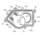
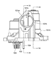
図6は、別な実施の形態である無段変速機の断面図である。図7は、図6の構成を矢印VII方向に見た図である。図8は、図6の構成を矢印VIII方向に見た図である。図9は、図8の構成を矢印IX方向に見た図である。図10(a)は、図9の構成を矢印X方向に見た図であり、図10(b)は、図10(a)の構成をXB-XB線で切断して矢印方向に見た図である。図11は、アクチュエータを図8と同様な方向から見た図である、カバー部材を外して示している。図12は、図11の構成を矢印XII方向に見た図である。図13は、カバー部材を内側から見た図である。   FIG. 6 is a cross-sectional view of a continuously variable transmission according to another embodiment. FIG. 7 is a view of the configuration of FIG. 6 as viewed in the direction of arrow VII. FIG. 8 is a view of the configuration of FIG. 6 as viewed in the direction of arrow VIII. FIG. 9 is a diagram of the configuration of FIG. 8 viewed in the direction of arrow IX. FIG. 10A is a view of the configuration of FIG. 9 viewed in the direction of the arrow X, and FIG. 10B is a view of the configuration of FIG. 10A taken along the line XB-XB and viewed in the direction of the arrow. FIG. FIG. 11 shows the actuator viewed from the same direction as in FIG. 8 with the cover member removed. 12 is a diagram of the configuration of FIG. 11 viewed in the direction of arrow XII. FIG. 13 is a view of the cover member as viewed from the inside.

アクチュエータ100’のハウジング101は、図10(a)に示すように、ハウジング本体101Aに一体的に形成された4つのステー101jにより支持されて、不図示のエンジンケース等に取り付けられる。組み付け時には、対向する2本のステー101jに形成されたノックピン穴101kに、図10(b)に点線で示すようなエンジンケースの中空ノックピンNKを挿入することでハウジング101を位置決め仮固定し、更に残りのステー101jに形成されたボルト穴101k’に、不図示のボルトを挿入することでハウジング101を取り付けることができる。   As shown in FIG. 10A, the housing 101 of the actuator 100 'is supported by four stays 101j formed integrally with the housing main body 101A, and is attached to an engine case (not shown) or the like. At the time of assembly, the housing 101 is positioned and temporarily fixed by inserting the hollow knock pin NK of the engine case as shown by the dotted line in FIG. 10B into the knock pin hole 101k formed in the two opposing stays 101j. The housing 101 can be attached by inserting a bolt (not shown) into the bolt hole 101k ′ formed in the remaining stay 101j.

図6に示すように、ハウジング101は、中空アルミ製のハウジング本体101Aと、その端面に対してボルトBTにより組み付けられたカバー部材101Bとからなる。ハウジング本体101Aの内部には、袋穴状のモータ室101aと、貫通穴状のねじ軸室(第2の孔)101bとが互いに連通することなく並設されている。モータ室内には、後述するようにして、外部の制御装置(不図示)によって制御されるモータ(ブレーキを有するサーボモータであると好ましい)102(図12)が固定されている。尚、アクチュエータ100’は、本実施の形態ではエンジンケースに固定され、図6に示すように、後述する駆動側プーリ部200の上部に配置されているが、これに対する変形例として、駆動側プーリ部200と従動側プーリ部の間で、ベルト211の内側に配置されても良い。   As shown in FIG. 6, the housing 101 includes a hollow aluminum housing main body 101 </ b> A and a cover member 101 </ b> B assembled to the end surface of the housing 101 by a bolt BT. Inside the housing body 101A, a bag hole-shaped motor chamber 101a and a through-hole-shaped screw shaft chamber (second hole) 101b are juxtaposed without communicating with each other. As will be described later, a motor (preferably a servo motor having a brake) 102 (FIG. 12) controlled by an external control device (not shown) is fixed in the motor chamber. In this embodiment, the actuator 100 ′ is fixed to the engine case, and is disposed on the upper side of a driving pulley section 200, which will be described later, as shown in FIG. It may be disposed inside the belt 211 between the portion 200 and the driven pulley portion.

図12において、電動のモータ102の回転軸102aの端部には、金属製の駆動ギヤ103が圧入により取り付けられている。駆動ギヤ103に隣接して、更に図11に示すように、歯数の大きな大ギヤ105aと、歯数の小さな小ギヤ105bとが樹脂より一体的に形成されてなり、ハウジング本体101Aに植設された支持軸104により回転自在に支持されている。大ギヤ105aは、駆動ギヤ103に噛合しており、小ギヤ105bは樹脂製の従動ギヤ106に噛合している。駆動ギヤ103と、大ギヤ105a及び小ギヤ105bからなるギヤ105と、従動ギヤ106とで減速機構を構成する。   In FIG. 12, a metal drive gear 103 is attached by press-fitting to the end of the rotating shaft 102a of the electric motor 102. As shown in FIG. 11, adjacent to the drive gear 103, a large gear 105a having a large number of teeth and a small gear 105b having a small number of teeth are integrally formed of resin, and are implanted in the housing body 101A. The support shaft 104 is rotatably supported. The large gear 105a meshes with the drive gear 103, and the small gear 105b meshes with the resin driven gear 106. The drive gear 103, the gear 105 including the large gear 105a and the small gear 105b, and the driven gear 106 constitute a reduction mechanism.

図6において、従動ギヤ106の内周にはスプライン雌溝が形成され、中空円筒状のナット部材107の端部外周に形成されたスプライン雄溝に係合して一体的に回転するように結合されている。但し、従動ギヤ106とナット部材107とは二面幅(平行な二面で周面をカットした構成)により相対回転を制限されていても良い。ナット部材107の外周には、玉軸受108の内輪が嵌合しており、かかる内輪は、ナット部材107の周溝に係合した止め輪114により軸線方向の相対変位が制限されている。一方、玉軸受108の外輪は、ハウジング本体101Aの端部の段部101sに嵌合しており、ビスBによりハウジング本体101Aに固定される軸受ホルダ109により抑えられている。ナット部材107の先端(図6で右端)外周は、ハウジング本体101Aの内周に対してブッシュ110により回転方向に摺動自在に支持されている。   In FIG. 6, a spline female groove is formed on the inner periphery of the driven gear 106, and is engaged with the spline male groove formed on the outer periphery of the end of the hollow cylindrical nut member 107 so as to rotate integrally. Has been. However, the relative rotation of the driven gear 106 and the nut member 107 may be limited by a two-surface width (a configuration in which the peripheral surface is cut by two parallel surfaces). An inner ring of a ball bearing 108 is fitted to the outer periphery of the nut member 107, and relative displacement in the axial direction of the inner ring is limited by a retaining ring 114 engaged with a circumferential groove of the nut member 107. On the other hand, the outer ring of the ball bearing 108 is fitted into a step portion 101s at the end of the housing main body 101A, and is restrained by a bearing holder 109 fixed to the housing main body 101A by screws B. The outer periphery of the front end (right end in FIG. 6) of the nut member 107 is supported by the bush 110 so as to be slidable in the rotational direction with respect to the inner periphery of the housing body 101A.

ねじ軸111は、ナット部材107に挿通され、雄ねじ溝111cを有するねじ部111aと、それに連結された丸軸部111bとから一体的に形成されてなる。ナット部材107の内周面には、雄ねじ溝111cに対向して、雌ねじ溝107aが形成され、両ねじ溝111c、107aによって形成される螺旋状の空間(転走路)には、多数のボール112が転動自在に配置されている。ナット部材107は、玉軸受108を介して、ハウジング本体101Aに対して軸線方向変位が制限され、回転のみ可能となっている。一方、ねじ軸111は、回り止め(不図示)により、ねじ軸室101b内において、軸線方向に相対移動可能だが、相対回転不能となっている。尚、軸線方向変位要素であるねじ軸111と、回転要素であるナット部材107と、転動体であるボール112とでボールねじ機構を構成する。又、ギヤ105とボールねじ機構とで、駆動機構を構成する。   The screw shaft 111 is formed integrally with a screw portion 111a inserted into the nut member 107 and having a male screw groove 111c, and a round shaft portion 111b connected thereto. A female screw groove 107a is formed on the inner peripheral surface of the nut member 107 so as to face the male screw groove 111c, and a plurality of balls 112 are formed in a spiral space (rolling path) formed by the both screw grooves 111c and 107a. Is arranged to roll freely. The nut member 107 is restricted in axial displacement with respect to the housing main body 101A via the ball bearing 108, and can only rotate. On the other hand, the screw shaft 111 can be relatively moved in the axial direction in the screw shaft chamber 101b by a detent (not shown), but cannot be relatively rotated. The screw shaft 111 that is an axial displacement element, the nut member 107 that is a rotating element, and the ball 112 that is a rolling element constitute a ball screw mechanism. The gear 105 and the ball screw mechanism constitute a drive mechanism.

ねじ軸111の詳細は後述するが、雄ねじ部111aの近傍における丸軸部111bの外周には、環状(ドーナツ円盤状)のセンサカラー113が圧入により固定され、雄ねじ部111aの段部(ランド部)に当接している。又、丸軸部111bは、ハウジング本体101Aの端部内周に対してブッシュ115により軸線方向に移動可能に支持されており、またブッシュ115の外方に隣接して配置されたシール116により、ハウジング本体101Aと丸軸部111bとの間が密封されている。ハウジング本体101Aから突出したねじ軸111の端部111dの外周には二面幅が形成されており、内周に対応する二面幅を有するドーナツ板状の押圧部材117(図6では下半分のみ断面で示す)が相対回転不能に嵌合している。   Although details of the screw shaft 111 will be described later, an annular (doughnut disk-shaped) sensor collar 113 is fixed to the outer periphery of the round shaft portion 111b in the vicinity of the male screw portion 111a by press-fitting, and a step portion (land portion) of the male screw portion 111a. ). Further, the round shaft portion 111b is supported by the bush 115 so as to be movable in the axial direction with respect to the inner periphery of the end portion of the housing main body 101A, and the housing 116 is provided with a seal 116 disposed adjacent to the outside of the bush 115. The space between the main body 101A and the round shaft portion 111b is sealed. The outer surface of the end 111d of the screw shaft 111 protruding from the housing main body 101A has a two-sided width, and a donut plate-shaped pressing member 117 having a two-sided width corresponding to the inner periphery (only the lower half in FIG. 6). (Shown in cross section) are fitted so that they cannot rotate relative to each other.

ハウジング本体101Aは、センサ118を取り付けている。センサ118の取り付け態様については後述する。   The housing main body 101A has a sensor 118 attached thereto. A mounting mode of the sensor 118 will be described later.

図13に一部点線で示すように、カバー部材101Bは、細長い金属製の板材を折り曲げてなる連結部材101x、101xを、樹脂製のカバー部材本体101zにインサート成形することによって形成されている。尚、カバー部材本体101zの端面の周囲は、O−リング用の溝101qが取り巻くように形成されており、その外方に突き出た部位には、金属製のチューブTBが5つインサート成形されており、チューブTB内に挿通されたボルト(不図示)により、ハウジング101Aに取り付けられるようになっている。又、カバー部材本体101zの最外周には、端面から紙面垂直方向に薄板状に突出したカバー部101wが形成されている。カバー部材101Bをハウジング本体101Aに組み付けたときに、カバー部101wがハウジング本体101Aの端面を取り巻くことで接合面のシール効果を高めるようになっている。   As shown in part by dotted lines in FIG. 13, the cover member 101B is formed by insert-molding connecting members 101x and 101x formed by bending an elongated metal plate material into a resin cover member main body 101z. Note that the periphery of the end surface of the cover member main body 101z is formed so as to surround an O-ring groove 101q, and five metal tubes TB are insert-molded at a portion protruding outward. And it is attached to the housing 101A by a bolt (not shown) inserted into the tube TB. A cover portion 101w is formed on the outermost periphery of the cover member main body 101z so as to protrude from the end surface in a thin plate shape in the direction perpendicular to the paper surface. When the cover member 101B is assembled to the housing main body 101A, the cover portion 101w surrounds the end surface of the housing main body 101A to enhance the sealing effect of the joint surface.

連結部材101xの外方端部は、カバー部材本体101zに形成された角筒状の連結部101y内に突出するようにインサート成形されている。   The outer end portion of the connecting member 101x is insert-molded so as to protrude into a rectangular tube-like connecting portion 101y formed in the cover member main body 101z.

図13において、カバー部材本体101zにおけるギヤ105の収容部の底部には、ギヤ105を支持する支持軸104の逃げ部(窪み)101dと、ギヤ105(図11)が軸線方向に移動することを阻止する環状のストッパ部(突起)101eとが一体的に形成されている。又、カバー部材101Bにおけるギヤ106(図11)の収容部の底部には、ギヤ106が軸線方向に移動することを阻止する弓状のストッパ部(突起)101fが一体的に形成されている。   In FIG. 13, at the bottom of the housing portion of the gear 105 in the cover member main body 101z, the escape portion (dent) 101d of the support shaft 104 that supports the gear 105 and the gear 105 (FIG. 11) move in the axial direction. An annular stopper portion (protrusion) 101e for blocking is formed integrally. In addition, an arcuate stopper portion (projection) 101f that prevents the gear 106 from moving in the axial direction is integrally formed at the bottom of the housing portion of the gear 106 (FIG. 11) in the cover member 101B.

カバー部材本体101zには、板金製の中間端子250の受け部101g、101gが角筒袋孔状に形成されている。受け部101g、101gの入口は奥側より寸法が小さく、中間端子250を受け部101gに取り付けた時、脱落しにくいようになっている。   In the cover member main body 101z, receiving portions 101g and 101g of an intermediate terminal 250 made of sheet metal are formed in a square tube bag shape. The inlets of the receiving portions 101g and 101g are smaller in size than the back side, and are difficult to drop off when the intermediate terminal 250 is attached to the receiving portion 101g.

連結部材101xの内方端部は、カバー部材本体101zの受け部101g内に突出するようにそれぞれインサート成形され、受け部101gに挿入された中間端子250と導通している。   The inward ends of the connecting member 101x are insert-molded so as to protrude into the receiving portion 101g of the cover member main body 101z, and are electrically connected to the intermediate terminal 250 inserted into the receiving portion 101g.

図14は、ギヤとセンサを取り外した状態で示す図12と同様な図であるが、モータ及びボールねじ機構を取り付けた状態で示している。図15は、図14の構成を矢印XV方向に見た図である。図16は、図15の構成を矢印XVI-XVI線で切断して矢印方向に見た図である。図17は、図15の構成を矢印XVII-XVII線で切断して矢印方向に見た図である。図18は、モータを外した状態で示す図14と同様な図である。図19は、図18の構成をXIX-XIX線で切断して矢印方向に見た図である。図20は、図18の構成をXX-XX線で切断して矢印方向に見た図である。図21は、モータを外した状態で示す図15と同様な図である。図22は、図21の構成をXXII-XXII線で切断して矢印方向に見た図である。   FIG. 14 is a view similar to FIG. 12 with the gear and sensor removed, but with the motor and ball screw mechanism attached. FIG. 15 is a diagram of the configuration of FIG. 14 viewed in the direction of the arrow XV. FIG. 16 is a view of the configuration of FIG. 15 taken along the arrow XVI-XVI line and viewed in the direction of the arrow. FIG. 17 is a view of the configuration of FIG. 15 taken along the line XVII-XVII and viewed in the direction of the arrow. FIG. 18 is a view similar to FIG. 14 with the motor removed. FIG. 19 is a view of the configuration of FIG. 18 taken along line XIX-XIX and viewed in the direction of the arrow. FIG. 20 is a view of the configuration of FIG. 18 taken along line XX-XX and viewed in the direction of the arrow. FIG. 21 is a view similar to FIG. 15 with the motor removed. 22 is a view of the configuration of FIG. 21 taken along line XXII-XXII and viewed in the direction of the arrow.

図16において、ハウジング本体101Aの端面に、ねじ軸111に平行して、円筒状の第1の孔101nが形成されおり、ねじ軸室(第2の孔)101bに交差する第3の孔101mに連通している。第1の孔101nには、支持軸104が圧入により嵌合している。入口が面取りされた第1の孔101nは、支持軸104の嵌合範囲のみ機械加工にて精度良く仕上げされている。但し、第1の孔101nに支持軸104を圧入したときに、ねじ軸室101bと第1の孔101nとの間に微小な隙間が生じる恐れもあるが、第1の孔101nの入口側は、カバー部材101B及びO−リングORによって密封されており、例え隙間が生じても、ここから塵埃等を内部に吸い込むことはない。又、ねじ軸室101bの図6で右端とねじ軸111との間は、シール116(図17参照)により密封されており、ねじ軸室101bの図6で左端側は、カバー部材101B及びO−リングORによって密封されているので、ここから塵埃等を内部に吸い込むこともない。   In FIG. 16, a cylindrical first hole 101n is formed in the end face of the housing main body 101A in parallel with the screw shaft 111, and a third hole 101m intersecting the screw shaft chamber (second hole) 101b. Communicating with The support shaft 104 is fitted into the first hole 101n by press fitting. The first hole 101n having a chamfered entrance is precisely finished by machining only the fitting range of the support shaft 104. However, when the support shaft 104 is press-fitted into the first hole 101n, there may be a small gap between the screw shaft chamber 101b and the first hole 101n, but the inlet side of the first hole 101n is The cover member 101B and the O-ring OR are sealed, and even if a gap is generated, dust or the like is not sucked into the interior. 6 is sealed with a seal 116 (see FIG. 17), and the left end side of the screw shaft chamber 101b in FIG. 6 is covered with the cover members 101B and O. -Since it is sealed by the ring OR, dust or the like is not sucked into the inside from here.

又、図16に示すように、ハウジング本体101Aの端面において、第1の孔101nの周囲の円筒状の外周部101rは、ハウジング本体101Aの端面周囲の、カバー部材101Bに当接した際に溝101q内のO−リングのシール面となる部位(当接部)101pと、第1の孔101nの軸線方向における位置が同じ、即ち面一となっている。これにより、比較的大型である同一の工具を用いて一度の加工で、当接部101pと外周部101rの加工を行うことが出来、加工効率を向上できる。   Also, as shown in FIG. 16, on the end surface of the housing body 101A, the cylindrical outer peripheral portion 101r around the first hole 101n is a groove when contacting the cover member 101B around the end surface of the housing body 101A. The position (contact portion) 101p serving as the seal surface of the O-ring in 101q and the position of the first hole 101n in the axial direction are the same, that is, flush with each other. Thereby, the contact part 101p and the outer peripheral part 101r can be processed by a single process using the same relatively large tool, and the processing efficiency can be improved.

図20において、ねじ軸室101bは、カバー部材101B側(図20で右側)より、軸受ホルダ109が組み付けられる第1内径部b1と、玉軸受108が嵌合する第2内径部b2と、ナット部材107が内包される第3内径部b3と、ブッシュ110が嵌合する第4内径部b4と、センサ118のアーム部を内包する第5内径部b5と、ブッシュ115が嵌合する第6内径部b6とを段階的に形成しており、この順序で内径が小さくなっている。尚、第6内径部b6に隣接して、それより大径のシール116の取付部b7を形成している。   20, the screw shaft chamber 101b includes a first inner diameter portion b1 to which the bearing holder 109 is assembled, a second inner diameter portion b2 into which the ball bearing 108 is fitted, and a nut from the cover member 101B side (right side in FIG. 20). A third inner diameter portion b3 in which the member 107 is contained, a fourth inner diameter portion b4 in which the bush 110 is fitted, a fifth inner diameter portion b5 in which the arm portion of the sensor 118 is contained, and a sixth inner diameter in which the bush 115 is fitted. The part b6 is formed in stages, and the inner diameter is reduced in this order. An attachment portion b7 of the seal 116 having a larger diameter is formed adjacent to the sixth inner diameter portion b6.

図23は、センサ118を取り付けた状態で示すハウジング101の斜視図であり、図24は、センサ118を取り外した状態で示すハウジング101の斜視図である。図25は、センサ118の上面図であり、図26は、センサ118の側面図であり、図27は、センサ118の下面図である。図28は、ねじ軸111の側面図である。図29は、ねじ軸111にセンサカラー113を取り付けた状態で示す図である。図30は、図29の構成をXXX-XXX線で切断して矢印方向に見た図である。   FIG. 23 is a perspective view of the housing 101 shown with the sensor 118 attached, and FIG. 24 is a perspective view of the housing 101 shown with the sensor 118 removed. 25 is a top view of the sensor 118, FIG. 26 is a side view of the sensor 118, and FIG. 27 is a bottom view of the sensor 118. FIG. 28 is a side view of the screw shaft 111. FIG. 29 is a diagram showing the sensor shaft 113 attached to the screw shaft 111. 30 is a diagram of the configuration of FIG. 29 taken along the line XXX-XXX and viewed in the direction of the arrow.

上述したように、ねじ軸111は、雄ねじ部111aと、丸軸部111bと、丸軸部111b側の端部111dとを、この順序で直接に連結した構成であるが、丸軸部111bの雄ねじ部111a側の部位がセンサカラー113の嵌合部111eであり、丸軸部111bの端部111d側の部位がブッシュ115(図6)の嵌合部(摺動部)111fである。ここで、センサカラー113の嵌合部111eの外径φ1と、ブッシュ115の嵌合部111fの外径φ2は、ねじ軸111の雄ねじ溝111cの溝底径φ3より小さく(φ1,φ2<φ3)なっている。このようにすることで、センサカラー113を嵌合部111eに確実に嵌合でき、かつブッシュ115は嵌合部111fに対して滑らかな相対摺動が可能となる。   As described above, the screw shaft 111 has a configuration in which the male screw portion 111a, the round shaft portion 111b, and the end portion 111d on the round shaft portion 111b side are directly connected in this order. The part on the male screw part 111a side is the fitting part 111e of the sensor collar 113, and the part on the end part 111d side of the round shaft part 111b is the fitting part (sliding part) 111f of the bush 115 (FIG. 6). Here, the outer diameter φ1 of the fitting portion 111e of the sensor collar 113 and the outer diameter φ2 of the fitting portion 111f of the bush 115 are smaller than the groove bottom diameter φ3 of the male screw groove 111c of the screw shaft 111 (φ1, φ2 <φ3). It has become. By doing so, the sensor collar 113 can be securely fitted to the fitting portion 111e, and the bush 115 can be smoothly slid relative to the fitting portion 111f.

ねじ軸111を製造する場合、一本の丸棒を転造加工することにより雄ねじ溝111cを複数箇所に形成し、次に必要な寸法に切断し、一本の丸棒から複数本のねじ軸素材を形成する。例えば、本実施の形態のアクチュエータ100’で必要なねじ軸111の長さは100mm程度であり、1m程度の丸軸を転造加工することにより、9本程度の実際に使用するねじ軸素材を得ることができる。次に、ねじ軸素材に対して、センサカラー113の嵌合部111eと、ブッシュ115の嵌合部111fを切削加工し、熱処理を行い、最後に研削加工を行うことで加工精度を高めている。センサカラー113の嵌合部111eと、ブッシュ115の嵌合部111fを、ねじ軸111の雄ねじ溝111cの溝底径より小さい径にすることにより、転造加工時にできた雄ねじ部111aが加工残りとはならず、均一の径に成形可能となる。また、センサカラー113を嵌合部111eに圧入した後、ねじ軸111の雄ねじ部111aの段部(盛り上がったランド部)に突き当てるようにすれば、これに支持されて倒れを少なく出来る。センサカラー113の嵌合部111eの外径φ1を、ブッシュ115の嵌合部111fの外径φ2より大きくすると、センサカラー113を端部111dから挿入する際、ブッシュ115の嵌合部111fを傷つける恐れが少なくなる。図6を参照して、ねじ軸111がハウジング本体101A内に最も引き込まれた際、センサカラー113とナット部材107が接触すると、ねじ軸111とナット部材107により締め込まれロックする恐れがある為、最大に引き込まれてもセンサカラー113とナット部材107が接触しないようになっていると好ましい。本実施の形態では、ねじ軸111はセンサカラー113がナット部材107に当接する前に樹脂カバー101Bに当接する。   When manufacturing the screw shaft 111, a single round bar is rolled to form male screw grooves 111c at a plurality of locations, then cut into necessary dimensions, and a single round rod is cut into a plurality of screw shafts. Form the material. For example, the length of the screw shaft 111 necessary for the actuator 100 ′ of the present embodiment is about 100 mm, and by rolling a round shaft of about 1 m, about nine screw shaft materials that are actually used are used. Can be obtained. Next, with respect to the screw shaft material, the fitting portion 111e of the sensor collar 113 and the fitting portion 111f of the bush 115 are cut, heat-treated, and finally subjected to grinding to increase the processing accuracy. . By making the fitting portion 111e of the sensor collar 113 and the fitting portion 111f of the bush 115 smaller than the groove bottom diameter of the male screw groove 111c of the screw shaft 111, the male screw portion 111a formed during the rolling process remains unprocessed. However, it becomes possible to mold to a uniform diameter. Further, if the sensor collar 113 is press-fitted into the fitting portion 111e and then abuts against the stepped portion (swelled land portion) of the male threaded portion 111a of the screw shaft 111, the sensor collar 113 is supported by this and the fall can be reduced. If the outer diameter φ1 of the fitting portion 111e of the sensor collar 113 is larger than the outer diameter φ2 of the fitting portion 111f of the bush 115, the fitting portion 111f of the bush 115 is damaged when the sensor collar 113 is inserted from the end portion 111d. There is less fear. Referring to FIG. 6, when the sensor shaft 113 and the nut member 107 come into contact with each other when the screw shaft 111 is most retracted into the housing main body 101A, the screw shaft 111 and the nut member 107 may be tightened and locked. It is preferable that the sensor collar 113 and the nut member 107 do not come into contact with each other even when pulled to the maximum. In the present embodiment, the screw shaft 111 contacts the resin cover 101 </ b> B before the sensor collar 113 contacts the nut member 107.

図25〜27に示すように、センサ118は、不図示のポテンショメータに連結されたセンサ軸118aを有するセンサ本体118bと、センサ軸118aを所定方向(図27の矢印方向)に付勢するコイルバネ118cと、センサ軸118aの先端に取り付けられた「へ」字状のアーム部118dと、センサ本体118bからの信号を外部に伝達するためのコネクタ部118eとからなる。センサ本体118bは、フランジ部118fと、フランジ部118fに隣接してセンサ軸118aと同軸である円筒状のインロー部118gとを有する。センサ118は、例えば回転式ポテンショメータやロータリエンコーダであって、センサ軸118aの回転角度に応じた信号を出力できるものであり、良く知られているため説明を省略する。尚、図18から明らかであるが、アーム部118dは、インロー部118gの外径より半径方向外方にはみ出している。   As shown in FIGS. 25 to 27, the sensor 118 includes a sensor main body 118b having a sensor shaft 118a coupled to a potentiometer (not shown), and a coil spring 118c that biases the sensor shaft 118a in a predetermined direction (the arrow direction in FIG. 27). And a “U” -shaped arm portion 118d attached to the tip of the sensor shaft 118a, and a connector portion 118e for transmitting a signal from the sensor main body 118b to the outside. The sensor main body 118b includes a flange portion 118f and a cylindrical spigot portion 118g adjacent to the flange portion 118f and coaxial with the sensor shaft 118a. The sensor 118 is, for example, a rotary potentiometer or a rotary encoder, and can output a signal corresponding to the rotation angle of the sensor shaft 118a. As is apparent from FIG. 18, the arm portion 118d protrudes outward in the radial direction from the outer diameter of the spigot portion 118g.

ハウジング本体101Aには、図15、22に示すように、ねじ軸室101bの軸線と直交する方向に延在し、ねじ軸室101bに連通するようにして、第3の孔101mが形成されている。第3の孔101mは、センサ118のインロー部118と同径である。   As shown in FIGS. 15 and 22, the housing body 101A has a third hole 101m that extends in a direction orthogonal to the axis of the screw shaft chamber 101b and communicates with the screw shaft chamber 101b. Yes. The third hole 101m has the same diameter as the spigot part 118 of the sensor 118.

センサ118をハウジング本体101Aの第3の孔101mに取り付ける際には、O−リングORをインロー部118gの外径に嵌めた状態で挿入するが、ハウジング本体101Aに対しインロー部118gを鉛直方向に向けるとO−リングORが落下する場合がある。しかし、センサ118を傾斜させることにより、O−リングORはインロー部118gに引っかかった状態となり、取り付け時に抜け落ちることが抑制される。尚、アーム部118dはセンサ本体118b内部のコイルバネ118cにより一方向に絶えず押されているため、センサ118がフリー状態である取り付け時にのみ、インロー部118gより突出していればよい。即ち、センサ可動時にアーム部118dがセンサ軸118aを中心に回転した場合には、アーム部118dの少なくとも先端は、インロー部118gの外径より内径側に位置する場合もあるということである。   When attaching the sensor 118 to the third hole 101m of the housing main body 101A, the O-ring OR is inserted with the outer diameter of the spigot portion 118g being inserted, but the spigot portion 118g is perpendicular to the housing main body 101A. If it is turned, the O-ring OR may fall. However, by inclining the sensor 118, the O-ring OR is caught by the spigot portion 118g and is prevented from falling off during attachment. Since the arm portion 118d is constantly pushed in one direction by the coil spring 118c inside the sensor body 118b, the arm portion 118d only has to protrude from the spigot portion 118g only when the sensor 118 is attached in a free state. That is, when the arm portion 118d rotates around the sensor shaft 118a when the sensor is movable, at least the tip of the arm portion 118d may be located on the inner diameter side of the outer diameter of the spigot portion 118g.

より具体的にセンサ118の組み付け手順を説明すると、まずインロー部118gにO−リングORを組み付けたセンサ118を斜めにして、突出したアーム部118dを先に第3の孔101m内に挿入し、アーム部118dがねじ軸室101b内に進入したら、第3の孔101mとインロー部118gの軸線を一致させて、センサ118を完全に押し込むと、O−リングORが、ハウジング本体101Aの第3の孔101mの周囲に形成されたテーパ状の面取り部101hに当接し、フランジ部118fとの間で、つぶれるように弾性変形するので、密封が有効に行われる。かかる状態で、ビスBをフランジ部101fのねじ孔に挿通して、ハウジング本体101Aのねじ孔に螺合させることで、センサ118の組付けを行うことができる。尚、センサ118を組み付けた状態では、図23に示すように、センサ118のコネクタ部118eが、カバー部材101Bのコネクタ用の連結部101yと同じ側を向いているので、不図示のコネクタを同じ側からそれぞれ差し込むことが出来、配線が容易である。   More specifically, the procedure for assembling the sensor 118 will be described. First, the sensor 118 having the O-ring OR assembled to the inlay portion 118g is inclined, and the protruding arm portion 118d is first inserted into the third hole 101m. When the arm portion 118d enters the screw shaft chamber 101b, when the axis of the third hole 101m and the inlay portion 118g are aligned with each other and the sensor 118 is completely pushed in, the O-ring OR is connected to the third hole of the housing body 101A. Since it abuts against the tapered chamfered portion 101h formed around the hole 101m and is elastically deformed so as to be crushed with the flange portion 118f, sealing is effectively performed. In this state, the sensor 118 can be assembled by inserting the screw B into the screw hole of the flange portion 101f and screwing it into the screw hole of the housing main body 101A. In the state where the sensor 118 is assembled, as shown in FIG. 23, the connector portion 118e of the sensor 118 faces the same side as the connector connecting portion 101y of the cover member 101B. Each side can be inserted and wiring is easy.

センサ118が組み付けられた状態で、アーム部118dは、その先端をねじ軸111に嵌合したセンサカラー113に当接させており、これによりセンサカラー113は、コイルバネ118cの弾性力によって、常時図6で左方(雄ねじ部111aの段部側)に押し付けられている。即ち、アーム部118dは、ねじ軸111に圧入嵌合されたセンサカラー113が抜けない方向に常時付勢している。このように、センサ118のアーム部118dにかかるコイルバネ118cのばね力を用いて、ねじ軸111に嵌合したセンサカラー113を抜けない方向に押圧することにより、センサカラー113がねじ軸111からずれてセンサ118の計測精度を低下させることを抑制できる。尚、センサカラー113を、ねじ軸11に嵌合する短円筒部と、それから半径方向に延在するフランジ部とから構成して、アーム部118dの先端をそれらの交差部に当接させるようにすると保持が確実となる。   In the state where the sensor 118 is assembled, the arm portion 118d is in contact with the sensor collar 113 fitted to the screw shaft 111 at the tip thereof, so that the sensor collar 113 is always illustrated by the elastic force of the coil spring 118c. 6 is pressed to the left (the stepped portion side of the male screw portion 111a). That is, the arm portion 118d is constantly biased in a direction in which the sensor collar 113 press-fitted and fitted to the screw shaft 111 does not come off. In this way, the sensor collar 113 is displaced from the screw shaft 111 by pressing the sensor collar 113 fitted to the screw shaft 111 in a direction not to be pulled out by using the spring force of the coil spring 118c applied to the arm portion 118d of the sensor 118. Therefore, it is possible to suppress the measurement accuracy of the sensor 118 from being lowered. The sensor collar 113 is composed of a short cylindrical portion fitted to the screw shaft 11 and a flange portion extending in the radial direction therefrom, and the tip of the arm portion 118d is brought into contact with the intersecting portion. Then, the holding is sure.

図6において、ねじ軸111が軸線方向右方に変位すると、センサカラー113によってセンサアーム118aが押され、ねじ軸118aが回転する。この回転量に応じて、センサ本体118b内のポテンショメータが対応する信号を発生するので、コネクタ部118eを介して信号を受けた外部の制御装置(不図示)は、センサ118が出力するこの信号に基づいて、ねじ軸111の軸線方向変位量を測定することができる。一方、センサ118内部に設けられたコイルバネ118cにより、アーム部118dはセンサカラー113を押圧する方向に付勢されているため、ねじ軸111が逆方向(図6で軸線方向左方)に変位した場合には、アーム118dもそれに追従することとなり、よってセンサ軸118aの回転量に応じて、センサ本体118b内のポテンショメータが対応する信号を発生することとなる。   In FIG. 6, when the screw shaft 111 is displaced rightward in the axial direction, the sensor arm 118a is pushed by the sensor collar 113, and the screw shaft 118a rotates. Since the potentiometer in the sensor main body 118b generates a corresponding signal in accordance with the rotation amount, an external control device (not shown) that receives the signal via the connector 118e receives the signal output from the sensor 118. Based on this, the amount of axial displacement of the screw shaft 111 can be measured. On the other hand, the arm portion 118d is biased in the direction of pressing the sensor collar 113 by the coil spring 118c provided in the sensor 118, so that the screw shaft 111 is displaced in the reverse direction (leftward in the axial direction in FIG. 6). In this case, the arm 118d also follows that, and accordingly, the potentiometer in the sensor main body 118b generates a corresponding signal according to the rotation amount of the sensor shaft 118a.

図31は、ハウジング本体101Aにモータ102を組み付ける際の状態を示す図14と同様な図である。図32は、図31の構成をXXXII-XXXII線で切断して矢印方向に見た図である。図33は、モータ102の側面図である。図34は、モータ組み付け用の治具Jの正面図であり、図35は、モータ組み付け用の治具Jの側面図である。   FIG. 31 is a view similar to FIG. 14 showing a state when the motor 102 is assembled to the housing main body 101A. 32 is a view of the configuration of FIG. 31 taken along the line XXXII-XXXII and viewed in the direction of the arrow. FIG. 33 is a side view of the motor 102. FIG. 34 is a front view of the motor assembling jig J, and FIG. 35 is a side view of the motor assembling jig J.

モータ102は、図32,33に示すように、回転軸102aを挟んで180度位相で、2つの金属製の平板状の端子102b、102bを突出させている。端子102b、102bの先端は円弧状であり、その根元には、樹脂製のボス102c、102cが形成されている。ボス102c、102cは、後述する中間端子250に端子102bを組み付けたとき、製造誤差などにより寸法バラツキが生じても、短絡を防止する機能を有する。更に、モータ102は、回転軸102aの根元に形成された、回転軸102aと同軸の円筒部102dと、モータ102から軸線直交方向に延在するフランジ部102fとを有している。円筒部102dの外径は、駆動ギヤ103の外径よりも大きい。   As shown in FIGS. 32 and 33, the motor 102 has two metal plate-like terminals 102b and 102b protruding at a phase of 180 degrees across the rotating shaft 102a. The tips of the terminals 102b and 102b are arc-shaped, and resin bosses 102c and 102c are formed at the bases thereof. The bosses 102c and 102c have a function of preventing a short circuit even if a dimensional variation occurs due to a manufacturing error or the like when the terminal 102b is assembled to an intermediate terminal 250 described later. Further, the motor 102 has a cylindrical portion 102d coaxial with the rotating shaft 102a and a flange portion 102f extending in the direction perpendicular to the axis from the motor 102, formed at the root of the rotating shaft 102a. The outer diameter of the cylindrical portion 102 d is larger than the outer diameter of the drive gear 103.

図34,35に示すように、治具Jは、駆動ギヤ103の外径より大きく且つ円筒部102dの外径に等しい内径を有する大穴J1と、支持軸104の外径に等しい内径を有する小穴J2とを有する。大穴J1が設けられた部位よりも、小穴J2が設けられた部位の方が厚さが厚いと好ましい。大穴J1と小穴J2との芯間距離は、駆動ギヤ103とギヤ105の芯間距離と等しくなっている。   As shown in FIGS. 34 and 35, the jig J has a large hole J1 having an inner diameter larger than the outer diameter of the drive gear 103 and equal to the outer diameter of the cylindrical portion 102d, and a small hole having an inner diameter equal to the outer diameter of the support shaft 104. J2. It is preferable that the portion where the small hole J2 is provided is thicker than the portion where the large hole J1 is provided. The center distance between the large hole J1 and the small hole J2 is equal to the center distance between the drive gear 103 and the gear 105.

モータ102をハウジング本体101Aに取り付ける場合、モータ102のフランジ部102fに設けた貫通穴(不図示)にボルトBTを通し、これをハウジング本体101Aに設けられたねじ穴に螺合させて固定する。その際、ギヤの負荷や摩耗を最適に調整する為に、モータ102の回転軸102aに取り付けた駆動ギヤ103と、それに噛合するギヤ105(図11,12)との芯間距離を、所定の寸法になるように位置決めする必要がある。   When the motor 102 is attached to the housing main body 101A, a bolt BT is passed through a through hole (not shown) provided in the flange portion 102f of the motor 102, and this is screwed into a screw hole provided in the housing main body 101A to be fixed. At that time, in order to optimally adjust the load and wear of the gear, the distance between the cores of the drive gear 103 attached to the rotating shaft 102a of the motor 102 and the gear 105 (FIGS. It is necessary to position so that it becomes the dimension.

ここで、モータ102の位置決めについて説明する。駆動ギヤ103を回転軸102aに圧入したモータ102を、図12に示すように、ハウジング本体101Aのモータ室101aに挿入する。かかる状態では、モータ室101aとモータ102との間に隙間があるため、モータ102の位置決めが必要となる。そこで、本実施の形態においては、支持軸104をモータ102の位置決めのために用いる。   Here, the positioning of the motor 102 will be described. As shown in FIG. 12, the motor 102 in which the drive gear 103 is press-fitted into the rotary shaft 102a is inserted into the motor chamber 101a of the housing main body 101A. In such a state, since there is a gap between the motor chamber 101a and the motor 102, the motor 102 must be positioned. Therefore, in the present embodiment, the support shaft 104 is used for positioning the motor 102.

より具体的には、治具Jの小穴J2を支持軸104に嵌合させ、且つ大穴J1を駆動ギヤ103の外径を通過させて円筒部102dに嵌合させる(図31,32)。これにより、駆動ギヤ103とギヤ105を支持する支持軸104の芯間距離が適切な値となる。かかる状態で、モータ102のフランジ部102fを、ボルトBTを用いてハウジング本体101Aに取り付けることにより、モータ102の位置決めが完了する。その後、治具Jは取り外されて、代わりにギヤ105が組み付けられる。   More specifically, the small hole J2 of the jig J is fitted to the support shaft 104, and the large hole J1 is fitted to the cylindrical portion 102d through the outer diameter of the drive gear 103 (FIGS. 31 and 32). Thereby, the distance between the centers of the support shafts 104 that support the drive gear 103 and the gear 105 becomes an appropriate value. In this state, the positioning of the motor 102 is completed by attaching the flange portion 102f of the motor 102 to the housing main body 101A using the bolt BT. Thereafter, the jig J is removed, and the gear 105 is assembled instead.

本実施の形態によれば、モータ102をハウジング本体101Aに取り付ける前に、支持軸104をハウジング本体101Aに圧入固定し、その後、支持軸104を基準として、モータ102の回転軸102aが所定の芯間距離になるように加工された治具Jを用いて、モータ102をハウジング本体101Aに対して精度良く位置決めすることができる。その為、駆動ギヤ103の歯先径は、回転軸102aを支持する軸受(不図示)が入るフランジ部102fより小さい径となっている。更に、樹脂製である他のギヤ105,106と異なり、駆動ギヤ103は、例えば鉄系の焼結部品であって、モータ102の回転軸102aに圧入嵌合される。従って、駆動ギヤ102をモータ102の回転軸102aに圧入する際にアキシャル力がかかるが、図33に示すように、かかる回転軸102aはモータケースの後端面より突出しており、この突出部分PJで圧入時のアキシャル力を支持することができる。   According to the present embodiment, before attaching the motor 102 to the housing main body 101A, the support shaft 104 is press-fitted and fixed to the housing main body 101A, and then the rotation shaft 102a of the motor 102 is fixed to a predetermined core with reference to the support shaft 104. The motor 102 can be accurately positioned with respect to the housing main body 101A by using the jig J processed so as to have a distance. Therefore, the tooth tip diameter of the drive gear 103 is smaller than the flange portion 102f into which a bearing (not shown) that supports the rotating shaft 102a is inserted. Further, unlike the other gears 105 and 106 made of resin, the drive gear 103 is, for example, an iron-based sintered part, and is press-fitted to the rotating shaft 102 a of the motor 102. Accordingly, an axial force is applied when the drive gear 102 is press-fitted into the rotating shaft 102a of the motor 102. However, as shown in FIG. 33, the rotating shaft 102a protrudes from the rear end surface of the motor case. Axial force during press fitting can be supported.

このようにして、モータ102を組み付けたハウジング本体101Aに対して、図13に示すカバー部材101Bを組み付けると、中間端子250の係合部(雌端子)内に、モータ102の端子102b、102bが進入して、導通が実現することとなる。即ち、カバー部材101Bをハウジング本体101Aに組み付けるのみで、モータ102から連結部材101xまでの配線が可能になる。   In this way, when the cover member 101B shown in FIG. 13 is assembled to the housing main body 101A to which the motor 102 is assembled, the terminals 102b and 102b of the motor 102 are placed in the engaging portion (female terminal) of the intermediate terminal 250. It will enter and conduction will be realized. That is, the wiring from the motor 102 to the connecting member 101x is possible only by assembling the cover member 101B to the housing main body 101A.

尚、無段変速機の駆動側プーリ部200及びフォーク部材300については、図1,5を参照して説明したものと同様であるため説明を省略する。   The driving pulley section 200 and the fork member 300 of the continuously variable transmission are the same as those described with reference to FIGS.

次に、無段変速機の動作について説明する。尚、ここでは説明を簡略化するために前進についてのみ説明し、後進については省略する。制御装置は、車速、エンジン回転数、アクセル開度等に基づいて、最適な変速比を選択する。選択した選択比に基づいて、アクチュエータ100’を駆動する。尚、動力を伝達している間中、ベルト211は、固定シーブ203より可動シーブ207が離隔する方向に力を付与しているため、フォーク部材300は常に反時計回りの方向に付勢されている。   Next, the operation of the continuously variable transmission will be described. Here, in order to simplify the description, only the forward movement will be described, and the backward movement will be omitted. The control device selects an optimum gear ratio based on the vehicle speed, the engine speed, the accelerator opening, and the like. The actuator 100 'is driven based on the selected selection ratio. During the transmission of power, the belt 211 applies a force in the direction in which the movable sheave 207 is separated from the fixed sheave 203, so that the fork member 300 is always urged counterclockwise. Yes.

ここで、制御装置が増速を指示したときは、モータ102に所定の極性の電力が供給され、回転軸102aが所定の方向に回転する。回転軸102aの回転力は、駆動ギヤ103,大ギヤ105a,小ギヤ105b、従動ギヤ106を介してナット部材107に伝達されるので、ナット部材107の回転に応じてねじ軸111が図6で右方へと変位する。ねじ軸111が右方に変位すると、押圧部材117も同方向に変位するので、それに当接しているアーム部301,301の上端が右方に押され、ベルト211の付勢力に抗して、フォーク部材300は図6で時計回りに揺動する。 Here, when the control device instructs to increase the speed , electric power having a predetermined polarity is supplied to the motor 102, and the rotating shaft 102a rotates in a predetermined direction. Since the rotational force of the rotating shaft 102a is transmitted to the nut member 107 through the drive gear 103, the large gear 105a, the small gear 105b, and the driven gear 106, the screw shaft 111 is shown in FIG. 6 according to the rotation of the nut member 107. Displace to the right. When the screw shaft 111 is displaced to the right, the pressing member 117 is also displaced in the same direction. Therefore, the upper ends of the arm portions 301 and 301 that are in contact with the screw shaft 111 are pushed to the right and resist the biasing force of the belt 211. The fork member 300 swings clockwise in FIG.

すると、アーム部301,301の下端が、軸受ホルダ209の外フランジ209bを左方に押圧するので、軸受ホルダ209は玉軸受208を介して可動シーブ207を左方に付勢する。このとき、可動シーブ207は回転しているが、フォーク部材300は回転していない。しかしながら、軸受ホルダ209と可動シーブ207との間には、玉軸受208が存在するので、摩擦等が生じず、早期摩耗や動力伝達ロス等を抑制できる。このように軸受ホルダ209を介して付勢されることで、プーリ軸201と共に回転しているスリーブ206に沿って、可動シーブ207が固定シーブ203に接近するように変位する(プーリ溝幅を小さくする)ので、ベルト211は、回転する円錐面203aと円錐面207bの間で挟持されながら、その半径方向外側へと移動する。一方、ベルト211により連結された、不図示の従動側プーリ部では、固定シーブから可動シーブが離隔するように駆動される。従って、駆動プーリ部200側ではベルト211のプーリ半径が大となり、従動プーリ側ではベルト211のプーリ半径が小となるので、入力軸の回転速度に対して出力軸の回転速度が増大し、増速を実現できる。制御装置は、センサ118からの信号に基づいて、所定位置までねじ軸111が変位したことを検知して、モータへの駆動制御を停止する。それにより、可動シーブ207の位置が固定されるので、ベルト211のプーリ半径が固定され、定速状態になる。 Then, the lower ends of the arm portions 301 and 301 press the outer flange 209 b of the bearing holder 209 to the left, so that the bearing holder 209 urges the movable sheave 207 to the left via the ball bearing 208. At this time, the movable sheave 207 is rotating, but the fork member 300 is not rotating. However, since the ball bearing 208 exists between the bearing holder 209 and the movable sheave 207, friction or the like does not occur, and early wear and power transmission loss can be suppressed. By being urged through the bearing holder 209 in this manner, the movable sheave 207 is displaced along the sleeve 206 rotating together with the pulley shaft 201 so as to approach the fixed sheave 203 (the pulley groove width is reduced). Therefore, the belt 211 moves outward in the radial direction while being sandwiched between the rotating conical surface 203a and the conical surface 207b. On the other hand, a driven pulley section (not shown) connected by the belt 211 is driven so that the movable sheave is separated from the fixed sheave. Thus, the pulley radius becomes large belt 211 in the drive pulley 200 side, the pulley radius of the belt 211 is small in the driven pulley side, the rotational speed of the output shaft relative to the rotational speed of the input shaft is increased, increasing Speed can be realized. Based on the signal from the sensor 118, the control device detects that the screw shaft 111 has been displaced to a predetermined position, and stops drive control to the motor. As a result, the position of the movable sheave 207 is fixed, so that the pulley radius of the belt 211 is fixed and a constant speed state is established.

これに対し、制御装置が減速を指示したときは、モータ102に上述とは逆の極性の電力が供給され、回転軸102aが逆方向に回転する。回転軸102aの回転力は、駆動ギヤ103,大ギヤ105a,小ギヤ105b、従動ギヤ106を介してナット部材107に伝達されるので、ナット部材107の回転に応じてねじ軸111が図6で左方へと変位する。ねじ軸111が左方に変位すると、押圧部材117も同方向に変位する。上述したように、フォーク部材300は、回転するベルト211によって反時計回りに付勢されているから、押圧部材117に当接しているアーム部301,301の上端は、それに追従して右方に変位し、よってフォーク部材300は図6で反時計回りに揺動する。すると、アーム部301,301の下端が右方に変位することで、軸受ホルダ209の抵抗が失せるので、可動シーブ207は、揺動した揺動部材300に制限される位置まで、ベルト211の付勢に従い右方に変位する(プーリ溝幅を大きくする)。これによりベルト211は、回転する円錐面203aと円錐面207bの間で挟持されながら、その半径方向内側へと移動する。一方、ベルト211により連結された、不図示の従動側プーリ部では、固定シーブに可動シーブが近接するように駆動される。従って、駆動プーリ部200側ではベルト211のプーリ半径が小となり、従動プーリ側ではベルト211のプーリ半径が大となるので、入力軸の回転速度に対して出力軸の回転速度が低下し、減速を実現できる。
On the other hand, when the control device instructs to decelerate , electric power having a polarity opposite to that described above is supplied to the motor 102, and the rotating shaft 102a rotates in the reverse direction. Since the rotational force of the rotating shaft 102a is transmitted to the nut member 107 through the drive gear 103, the large gear 105a, the small gear 105b, and the driven gear 106, the screw shaft 111 is shown in FIG. 6 according to the rotation of the nut member 107. Displace to the left. When the screw shaft 111 is displaced leftward, the pressing member 117 is also displaced in the same direction. As described above, since the fork member 300 is urged counterclockwise by the rotating belt 211, the upper ends of the arm portions 301 and 301 that are in contact with the pressing member 117 follow and move rightward. Therefore, the fork member 300 swings counterclockwise in FIG. Then, since the lower ends of the arm portions 301 and 301 are displaced to the right, the resistance of the bearing holder 209 is lost, so that the movable sheave 207 is attached to the belt 211 to a position limited by the swinging swinging member 300. Displaces to the right according to the force (increases pulley groove width). Accordingly, the belt 211 moves inward in the radial direction while being sandwiched between the rotating conical surface 203a and the conical surface 207b. On the other hand, a driven pulley section (not shown) connected by the belt 211 is driven so that the movable sheave is close to the fixed sheave. Thus, the pulley radius small next to the belt 211 by the driving pulley unit 200 side, since the pulley radius of the belt 211 is large at the driven pulley side, the rotational speed of the output shaft relative to the rotational speed of the input shaft is reduced, decelerated Can be realized.

本実施の形態によれば、ボールねじ機構のねじ軸111をプーリ軸201と並列に配置し、揺動するフォーク部材300にて、ねじ軸111の軸線方向変位を可動シーブ207の軸線方向変位に変換しているため、ナット部材107の慣性を抑えることが出来、プーリ幅の高速制御を容易に行える。又、フォーク部材300を介在させることで、ベルト211の付勢力で可動シーブ207が傾いても、ねじ軸111の傾きを招来しないので、疲労寿命等の低下を抑制できる。   According to the present embodiment, the screw shaft 111 of the ball screw mechanism is arranged in parallel with the pulley shaft 201, and the axial displacement of the screw shaft 111 is changed to the axial displacement of the movable sheave 207 by the swinging fork member 300. Because of the conversion, the inertia of the nut member 107 can be suppressed, and the pulley width can be easily controlled at high speed. Further, by interposing the fork member 300, even if the movable sheave 207 is tilted by the urging force of the belt 211, the screw shaft 111 is not tilted, so that a decrease in fatigue life and the like can be suppressed.

更に本実施の形態によれば、第1の孔101nから第3の孔101mまで連通しており、第1の孔101nはカバー部材101BとO−リングORにより密封され、第2の孔であるねじ軸室101bはシール116とカバー部材101BとO−リングORにより密封され、第3の孔101mはセンサ118により密封されているので、これによりねじ軸室101bが密封され閉鎖空間となることから、第1の孔101nと支持軸104との加工精度に関わらず、第1の孔101mを通って外部から異物が侵入することが抑制される。   Further, according to the present embodiment, the first hole 101n communicates with the third hole 101m, and the first hole 101n is sealed by the cover member 101B and the O-ring OR and is the second hole. Since the screw shaft chamber 101b is sealed by the seal 116, the cover member 101B, and the O-ring OR, and the third hole 101m is sealed by the sensor 118, the screw shaft chamber 101b is thereby sealed and becomes a closed space. Regardless of the processing accuracy of the first hole 101n and the support shaft 104, the entry of foreign matter from the outside through the first hole 101m is suppressed.

図36は、上述した実施の形態にかかる無段変速機を実機に搭載した状態を示す図である。図36において、駆動プーリ部200を含む無段変速機は、板材からなるハウジングHSに覆われている。一方、アクチュエータ100は、ハウジングHSの外部に設けられている。ハウジングHSは、開口SL(2つのスリットであると好ましい)を有している。フォーク部材300が開口SLを通過してハウジングHSの内外に延在しており、上述したようにしてアーム部301,301の上端が、アクチュエータ100の押圧部材117に右面に当接し、アーム部301,301の下端が、駆動側プーリ部200における軸受ホルダ209の外フランジ209bの右面に当接している。アクチュエータ100の駆動時にフォーク部材300が揺動しても、ハウジングHSと干渉することはない。 FIG. 36 is a diagram showing a state in which the continuously variable transmission according to the above-described embodiment is mounted on an actual machine. In FIG. 36, the continuously variable transmission including the driving pulley unit 200 is covered with a housing HS made of a plate material. On the other hand, the actuator 100 is provided outside the housing HS. The housing HS has an opening SL (preferably two slits). The fork member 300 passes through the opening SL and extends in and out of the housing HS. As described above, the upper ends of the arm portions 301 and 301 abut against the pressing member 117 of the actuator 100 on the right surface, and the arm portion 301 , 301 is in contact with the right surface of the outer flange 209 b of the bearing holder 209 in the driving pulley section 200. Even if the fork member 300 swings when the actuator 100 is driven, it does not interfere with the housing HS.

ここで、アクチュエータを無段変速機と共にハウジング内部に収容した場合、不図示のエンジンからの受熱によりモータの性能低下を招きやすく、また作動によるモータ自身の熱を十分に放熱することができない恐れがある。更に、アクチュエータ内部に塵埃等が侵入しやすくなり、ボールねじ機構やセンサへの影響を回避すべく、防塵シールを強固にしなくてはならず、コスト高を招く恐れがある。これに対し、本実施の形態のように、アクチュエータ100をハウジングHSの外部に配置すると、熱の問題を緩和することが出来、また防塵シール等は簡素なもので足り、より低コスト化を図ることができる。 Here, if the actuator is housed in the housing together with the continuously variable transmission, the performance of the motor is likely to be reduced due to heat received from an engine (not shown), and the heat of the motor itself due to operation may not be sufficiently dissipated. is there. Furthermore, dust or the like easily enters the actuator, and the dust-proof seal must be strengthened to avoid the influence on the ball screw mechanism and the sensor, which may increase the cost. On the other hand, when the actuator 100 is arranged outside the housing HS as in the present embodiment, the problem of heat can be alleviated, and a simple dust-proof seal or the like is sufficient, thereby further reducing the cost. be able to.

図37は、別な実施の形態にかかる無段変速機を実機に搭載した状態を示す図である。図37に示す無段変速機は、固定シーブ203及び可動シーブ207を備えた駆動プーリ部200と、固定シーブ253及び可動シーブ257を備えた従動プーリ部250とを有し、互いに軸線を平行にした駆動プーリ部200と従動プーリ部250とはベルト211により連結され、同期して回転するようになっている。上述した実施の形態と同様な構成を有するアクチュエータ100は、駆動プーリ部200の軸線直交方向に見たときに、駆動プーリ部200と従動プーリ部250との間に配置されている。レイアウト以外については、上述した実施の形態と基本的に同様な構成であるため、詳細は説明しない。本実施の形態のように、アクチュエータ100を、駆動プーリ部200と従動プーリ部250との間の空いたスペースに配置すると、無段変速機の軸線方向長さを短縮でき、コンパクトな無段変速機を提供することができる。 FIG. 37 is a diagram showing a state in which a continuously variable transmission according to another embodiment is mounted on an actual machine. The continuously variable transmission shown in FIG. 37 has a drive pulley 200 having a fixed sheave 203 and a movable sheave 207, and a driven pulley 250 having a fixed sheave 253 and a movable sheave 257, and the axes are parallel to each other. The driven pulley section 200 and the driven pulley section 250 are connected by a belt 211 so as to rotate synchronously. The actuator 100 having the same configuration as that of the above-described embodiment is disposed between the drive pulley unit 200 and the driven pulley unit 250 when viewed in the direction orthogonal to the axis of the drive pulley unit 200. Since the configuration other than the layout is basically the same as that of the above-described embodiment, the details will not be described. As in this embodiment, the actuator 100, when placed in the empty space between the drive pulley 200 and the driven pulley portion 250, can reduce the axial length of the continuously variable transmission, a compact continuously variable transmission Machine can be provided.

以上、本発明を実施の形態を参照して説明してきたが、本発明は上記実施の形態に限定して解釈されるべきではなく、適宜変更・改良が可能であることはもちろんである。例えば、ねじ軸を回転要素とし、ナット部材を軸線方向変位要素としても良い。   The present invention has been described above with reference to the embodiments. However, the present invention should not be construed as being limited to the above-described embodiments, and can be modified or improved as appropriate. For example, the screw shaft may be a rotating element and the nut member may be an axial displacement element.

第1の実施の形態である無段変速機の断面図である。It is sectional drawing of the continuously variable transmission which is 1st Embodiment. 図1の構成をカバー部材を外した状態で矢印II方向に見た図であり、ギヤ歯を省略して示している。It is the figure which looked at the structure of FIG. 1 in the arrow II direction in the state which removed the cover member, and has abbreviate | omitted and shown the gear tooth. 図1の構成をカバー部材を外した状態で矢印III方向に見た図である。It is the figure which looked at the structure of FIG. 1 in the arrow III direction in the state which removed the cover member. 図1の構成を矢印IV方向に見た図であるが、ハウジングは省略している。FIG. 4 is a diagram of the configuration of FIG. 1 viewed in the direction of an arrow IV, but a housing is omitted. フォーク部材の正面図(a)、側面図(b)及び斜視図(c)である。It is the front view (a), side view (b), and perspective view (c) of a fork member. 第2の実施の形態である無段変速機の断面図である。It is sectional drawing of the continuously variable transmission which is 2nd Embodiment. 図6の構成を矢印VII方向に見た図である。It is the figure which looked at the structure of FIG. 6 in the arrow VII direction. 図7の構成を矢印VIII方向に見た図である。It is the figure which looked at the structure of FIG. 7 in the arrow VIII direction. 図8の構成を矢印IX方向に見た図である。It is the figure which looked at the structure of FIG. 8 in the arrow IX direction. 図10(a)は、図9の構成を矢印X方向に見た図であり、図10(b)は、図10(a)の構成をXB-XB線で切断して矢印方向に見た図である。FIG. 10A is a view of the configuration of FIG. 9 viewed in the direction of the arrow X, and FIG. 10B is a view of the configuration of FIG. 10A taken along the line XB-XB and viewed in the direction of the arrow. FIG. アクチュエータを図8と同様な方向から見た図である、カバー部材を外して示している。It is the figure which looked at the actuator from the same direction as FIG. 8, and removes and shows the cover member. 図11の構成を矢印XII方向に見た図である。It is the figure which looked at the structure of FIG. 11 in the arrow XII direction. カバー部材を内側から見た図である。It is the figure which looked at the cover member from the inside. ギヤとセンサを取り外した状態で示す図12と同様な図であるが、モータ及びボールねじ機構を取り付けた状態で示している。FIG. 13 is a view similar to FIG. 12 with the gear and sensor removed, but with the motor and ball screw mechanism attached. 図4の構成を矢印XV方向に見た図である。It is the figure which looked at the structure of FIG. 4 in the arrow XV direction. 図15の構成を矢印XVI-XVI線で切断して矢印方向に見た図である。It is the figure which cut | disconnected the structure of FIG. 15 by the arrow XVI-XVI line, and looked at the arrow direction. 図15の構成を矢印XVII-XVII線で切断して矢印方向に見た図である。It is the figure which cut | disconnected the structure of FIG. 15 by the arrow XVII-XVII line, and looked at the arrow direction. モータを外した状態で示す図14と同様な図である。It is a figure similar to FIG. 14 shown in the state which removed the motor. 図18の構成をXIX-XIX線で切断して矢印方向に見た図である。It is the figure which cut | disconnected the structure of FIG. 18 by the XIX-XIX line, and looked at the arrow direction. 図18の構成をXX-XX線で切断して矢印方向に見た図である。It is the figure which cut | disconnected the structure of FIG. 18 by the XX-XX line and looked at the arrow direction. モータを外した状態で示す図20と同様な図である。It is the same figure as FIG. 20 shown in the state which removed the motor. 図21の構成をXXII-XXII線で切断して矢印方向に見た図である。It is the figure which cut | disconnected the structure of FIG. 21 with the XXII-XXII line | wire, and looked at the arrow direction. センサ118を取り付けた状態で示すハウジング101の斜視図である。It is a perspective view of the housing 101 shown in the state which attached the sensor 118. FIG. センサ118を取り外した状態で示すハウジング101の斜視図である。It is a perspective view of the housing 101 shown in a state where the sensor 118 is removed. センサ118の上面図である。2 is a top view of a sensor 118. FIG. センサ118の側面図である。2 is a side view of a sensor 118. FIG. センサ118の下面図である。It is a bottom view of the sensor 118. FIG. ねじ軸111の側面図である。3 is a side view of a screw shaft 111. FIG. ねじ軸111にセンサカラー113を取り付けた状態で示す図である。It is a figure shown in the state where sensor collar 113 was attached to screw axis 111. 図29の構成をXXX-XXX線で切断して矢印方向に見た図である。It is the figure which cut | disconnected the structure of FIG. 29 by the XXX-XXX line and looked at the arrow direction. ハウジング本体101Aにモータを組み付ける際の状態を示す図14と同様な図である。It is a figure similar to FIG. 14 which shows the state at the time of attaching a motor to the housing main body 101A. 図31の構成をXXXII-XXXII線で切断して矢印方向に見た図である。FIG. 32 is a view of the configuration of FIG. 31 taken along the line XXXII-XXXII and viewed in the direction of the arrow. モータ102の側面図である。2 is a side view of a motor 102. FIG. モータ組み付け用の治具Jの正面図である。It is a front view of the jig | tool J for motor assembly | attachment. モータ組み付け用の治具Jの側面図である。It is a side view of the jig | tool J for motor assembly | attachment. 上述した実施の形態にかかる無段変速機を実機に搭載した状態を示す図である。It is a figure which shows the state which mounted the continuously variable transmission concerning embodiment mentioned above in the actual machine. 別な実施の形態にかかる無段変速機を実機に搭載した状態を示す図である。It is a figure which shows the state which mounted the continuously variable transmission concerning another embodiment in the actual machine.

符号の説明Explanation of symbols

100、100’ アクチュエータ
101 ハウジング
101A ハウジング本体
101B カバー部材
101a モータ室
101b ねじ軸室
101d 段部
101e 長孔
101f ストッパ部
101g インロー部
101g 受け部
101h 面取り部
101j ステー
101k ノックピン穴
101k’ ボルト穴
101m 第3の孔
101n 第1の孔
101p 当接部
101q 溝
101r 外周部
101s 段部
101w カバー部
101x 連結部材
101y 連結部
101z カバー部材本体
102 モータ
102a 回転軸
102b 端子
102c ボス
102d 円筒部
102f フランジ部
103 駆動ギヤ
104 中間軸
105a 大ギヤ
105b 小ギヤ
106 従動ギヤ
107 ナット部材
107a 雌ねじ溝
108 玉軸受
109 軸受ホルダ
110 ブッシュ
111 ねじ軸
111a ねじ部
111b 丸軸部
111c 雄ねじ溝
111d 端部
111e 嵌合部
111f 嵌合部
112 ボール
113 センサカラー
114 止め輪
115 ブッシュ
116 シール
117 押圧部材
118 センサ
118a センサアーム
118b 回転板
118c コイルバネ
118d アーム部
118e コネクタ部
118f フランジ部
118g インロー部
119 止め輪
200 駆動プーリ部
201 プーリ軸
201a 雄ねじ部
201b スプライン雄溝
202 玉軸受
203 固定シーブ
203a 円錐面
203b スプライン雌溝
204 ワッシャ
206 スリーブ
206a スプライン雄溝
206 スリーブ
207 可動シーブ
207a 中央筒部
207b 円錐面
207c スプライン雌溝
208 玉軸受
209 軸受ホルダ
209a 円筒部
209b 外フランジ
209c 内フランジ
210 ストッパ
211 ベルト
215 ナット
250 従動プーリ部
253 固定シーブ
257 可動シーブ
300 フォーク部材
301 アーム部
301a 孔
302 架橋部
302a 溝
B ビス
BT ボルト
J 治具
J1 大穴
J2 小穴
OR O−リング
PJ 突出部分
S シャフト
TB チューブ
100, 100 'Actuator 101 Housing 101A Housing body 101B Cover member 101a Motor chamber 101b Screw shaft chamber 101d Stepped portion 101e Long hole 101f Stopper portion 101g Slotted portion 101g Receiving portion 101h Chamfered portion 101j Stay 101k Knock pin hole 101k' Bolt hole 101m Third Hole 101n first hole 101p contact part 101q groove 101r outer periphery part 101s step part 101w cover part 101x connecting member 101y connecting part 101z cover member body 102 motor 102a rotating shaft 102b terminal 102c boss 102d cylindrical part 102f flange part 103 drive gear 104 Intermediate shaft 105a Large gear 105b Small gear 106 Driven gear 107 Nut member 107a Female thread groove 108 Ball bearing 109 Bearing holder 110 Bush 111 Threaded shaft 111a Screw portion 111b Round shaft portion 111c Male thread groove 111d End portion 111e Fitting portion 111f Fitting portion 112 Ball 113 Sensor collar 114 Retaining ring 115 Bush 116 Seal 117 Press member 118 Sensor 118a Sensor arm 118b Rotating plate 118c Coil spring 118d Arm Portion 118e connector portion 118f flange portion 118g spigot portion 119 retaining ring 200 driving pulley portion 201 pulley shaft 201a male screw portion 201b spline male groove 202 ball bearing 203 fixed sheave 203a conical surface 203b spline female groove 204 washer 206 sleeve 206a spline male groove 206 sleeve 207 Movable sheave 207a Central tube portion 207b Conical surface 207c Spline female groove 208 Ball bearing 209 Bearing holder 209a Cylindrical portion 209b 209c Inner flange 210 Stopper 211 Belt 215 Nut 250 Driven pulley portion 253 Fixed sheave 257 Movable sheave 300 Fork member 301 Arm portion 301a Hole 302 Bridge portion 302a Groove B Screw BT Bolt J Jig J1 Large hole J2 Small hole OR O-ring PJ Projection Part S Shaft TB Tube

Claims (7)

駆動源に連結された駆動プーリ軸に固定支持された固定シーブ及び前記駆動プーリ軸に沿って軸線方向移動可能に支持された可動シーブとからなる駆動プーリ部と,該駆動プーリ軸に平行に配置されている従動プーリ軸に固定支持された固定シーブ及び前記従動プーリ軸に沿って軸線方向移動可能に支持された可動シーブとからなる従動プーリ部と,前記駆動プーリ部と前記従動プーリ部との間に掛け渡されたVベルトと,前記駆動プーリ部の可動シーブを移動させるための揺動不能に固定されたアクチュエータと,このアクチュエータの動力を前記駆動プーリ部の可動シーブへ伝達する動力伝達部とを備え、
前記駆動プーリ部の可動シーブは駆動源側に配置され、前記駆動プーリ部の固定シーブは駆動源から遠い側に配置されており、
前記アクチュエータは、電動モータと、前記電動モータが発生した回転力を伝達する減速機構と、前記減速機構を介して前記電動モータの動力を入力する回転要素と、前記回転要素の回転量に応じて軸線方向に変位する軸線方向変位要素と、一端前記軸線方向変位要素の軸線直交面に摺動可能に当接し、他端軸受を保持する軸受ホルダの軸線直交面に摺動可能に当接してなり、該軸受及び該軸受ホルダを介して前記駆動プーリ部の可動シーブを付勢するための部材とを有し、前記軸線方向変位要素の変位に応じて、前記部材が揺動して前記駆動プーリ部の可動シーブを前記駆動プーリ部の固定シーブに対して移動させるようになっており、
前記軸受は、前記駆動プーリ部の可動シーブに内輪を固定し、前記軸受ホルダに外輪を固定してなることを特徴とする無段変速機。
A drive pulley portion comprising a fixed sheave fixedly supported by a drive pulley shaft connected to a drive source and a movable sheave supported so as to be movable in the axial direction along the drive pulley shaft, and disposed parallel to the drive pulley shaft A driven sheave portion comprising a fixed sheave fixedly supported by the driven pulley shaft and a movable sheave supported so as to be movable in the axial direction along the driven pulley shaft, and a drive pulley portion and a driven pulley portion. a V-belt passed over between the actuators non-pivoting fixed for moving the movable sheave of the drive pulley portion, a power transmission unit for transmitting the power of the actuator to the movable sheave of the drive pulley unit And
The movable sheave of the drive pulley unit is disposed on the drive source side, and the fixed sheave of the drive pulley unit is disposed on the side far from the drive source,
The actuator includes an electric motor, a speed reduction mechanism that transmits a rotational force generated by the electric motor, a rotation element that inputs power of the electric motor via the speed reduction mechanism, and a rotation amount of the rotation element and axial displacement element that is displaced in the axial direction, one end slidably contact with the axial line orthogonal plane of the axial displacement element and the other end slidably in contact with the axis orthogonal plane of the bearing holder for holding a bearing And a member for urging the movable sheave of the drive pulley portion via the bearing and the bearing holder, and the member swings according to the displacement of the axial displacement element and The movable sheave of the drive pulley portion is moved with respect to the fixed sheave of the drive pulley portion ,
The continuously variable transmission according to claim 1, wherein the bearing has an inner ring fixed to a movable sheave of the drive pulley portion and an outer ring fixed to the bearing holder.
前記アクチュエータは、前記駆動プーリ部の軸線直交方向に見たときに、前記駆動プーリ部と前記従動プーリ部との間に配置されていることを特徴とする請求項1に記載の無段変速機。   2. The continuously variable transmission according to claim 1, wherein the actuator is disposed between the drive pulley and the driven pulley when viewed in a direction orthogonal to the axis of the drive pulley. . 前記軸線方向変位要素は、前記駆動プーリ軸又は前記従動プーリ軸と平行に配置されていることを特徴とする請求項1又は2に記載の無段変速機。   The continuously variable transmission according to claim 1 or 2, wherein the axial direction displacement element is arranged in parallel with the drive pulley shaft or the driven pulley shaft. 前記アクチュエータは、前記無段変速機を覆っているハウジングに対して外部に設けられていることを特徴とする請求項1〜3のいずれかに記載の無段変速機。   The continuously variable transmission according to any one of claims 1 to 3, wherein the actuator is provided outside a housing that covers the continuously variable transmission. 前記回転要素はナット又はねじ軸であり、前記軸線方向変位要素はねじ軸又はナットであり、前記ナット及び前記ねじ軸によりボールねじ機構を構成することを特徴とする請求項1〜4のいずれかに記載の無段変速機。   The rotary element is a nut or a screw shaft, the axial direction displacement element is a screw shaft or a nut, and the nut and the screw shaft constitute a ball screw mechanism. The continuously variable transmission described in 1. 前記軸線方向変位要素の軸線方向移動量を検出するセンサを有し、前記センサは、回転式ポテンシヨメータを含むことを特徴とする請求項1〜5のいずれかに記載の無段変速機。   The continuously variable transmission according to any one of claims 1 to 5, further comprising a sensor that detects an axial movement amount of the axial displacement element, wherein the sensor includes a rotary potentiometer. 前記アクチュエータは、前記電動モータを取り付けたハウジング本体とカバー部材とを含むハウジングと、前記軸線方向変位要素の軸線方向移動量を検出するセンサと、を有し、前記減速機構はギヤを含み、
前記ハウジング本体は、前記ギヤの支持軸を嵌合する第1の孔と、前記軸線方向変位要素を収容する第2の孔とを、それらの軸線が互いに平行になるように形成すると共に、前記センサを取り付けるための第3の孔を、前記第2の孔に対して交差させて形成しており、
前記第1の孔から前記第3の孔まで連通しており、前記第2の孔はシールにより密封され、前記第3の孔は前記センサにより密封されていることを特徴とする請求項1〜6のいずれかに記載の無段変速機。
The actuator includes a housing including a housing main body to which the electric motor is attached and a cover member, and a sensor for detecting an axial movement amount of the axial displacement element, and the speed reduction mechanism includes a gear,
The housing body is formed with a first hole for fitting the support shaft of the gear and a second hole for housing the axial displacement element so that the axes are parallel to each other, and A third hole for mounting the sensor is formed to intersect the second hole;
The first hole is communicated with the third hole, the second hole is sealed with a seal, and the third hole is sealed with the sensor. The continuously variable transmission according to any one of 6.
JP2008209690A 2007-09-05 2008-08-18 Continuously variable transmission Expired - Fee Related JP5669347B2 (en)

Priority Applications (5)

Application Number Priority Date Filing Date Title
JP2008209690A JP5669347B2 (en) 2007-09-05 2008-08-18 Continuously variable transmission
PCT/JP2008/066125 WO2009031669A1 (en) 2007-09-05 2008-09-05 Continuously variable transmission, actuator, and intermediate terminal
US12/676,439 US20100184543A1 (en) 2007-09-05 2008-09-05 Continuously variable transmission, actuator and intermediate terminal
CN200880105874A CN101796326A (en) 2007-09-05 2008-09-05 Continuously variable transmission, actuator, and intermediate terminal
EP08829547.2A EP2187095A4 (en) 2007-09-05 2008-09-05 Continuously variable transmission, actuator, and intermediate terminal

Applications Claiming Priority (3)

Application Number Priority Date Filing Date Title
JP2007230105 2007-09-05
JP2008209690A JP5669347B2 (en) 2007-09-05 2008-08-18 Continuously variable transmission

Publications (3)

Publication Number Publication Date
JP2009079759A JP2009079759A (en) 2009-04-16
JP2009079759A5 JP2009079759A5 (en) 2011-10-13
JP5669347B2 true JP5669347B2 (en) 2015-02-12

Family

ID=40654655

Family Applications (1)

Application Number Title Priority Date Filing Date
JP2008209690A Expired - Fee Related JP5669347B2 (en) 2007-09-05 2008-08-18 Continuously variable transmission

Country Status (1)

Country Link
JP (1) JP5669347B2 (en)

Families Citing this family (9)

* Cited by examiner, † Cited by third party
Publication number Priority date Publication date Assignee Title
JP5241642B2 (en) * 2009-07-30 2013-07-17 本田技研工業株式会社 V belt type continuously variable transmission
JP5598021B2 (en) * 2010-02-26 2014-10-01 日本精工株式会社 Continuously variable transmission and actuator
ES2564036T3 (en) 2013-03-29 2016-03-17 Musashi Seimitsu Industry Co., Ltd. V-belt continuous variation transmission
JP6002614B2 (en) * 2013-03-29 2016-10-05 武蔵精密工業株式会社 V belt type continuously variable transmission
JP6176060B2 (en) * 2013-11-04 2017-08-09 日本精工株式会社 Electric actuator
JP6461468B2 (en) 2013-11-22 2019-01-30 Ntn株式会社 V belt type continuously variable transmission
JP5688482B2 (en) * 2014-03-26 2015-03-25 本田技研工業株式会社 Continuously variable transmission structure
JP6297016B2 (en) 2015-10-23 2018-03-20 本田技研工業株式会社 Belt type continuously variable transmission for work equipment
CN117704038B (en) * 2024-02-06 2024-04-09 山东欧迈机械股份有限公司 Vertical heavy-load oil-tight gearbox

Family Cites Families (8)

* Cited by examiner, † Cited by third party
Publication number Priority date Publication date Assignee Title
JPS5926937U (en) * 1982-08-12 1984-02-20 ヤンマー農機株式会社 Combine threshing drive
US5048302A (en) * 1990-02-09 1991-09-17 Hudson Associates, Inc. Refrigerant system having controlled variable speed drive for compressor
JPH05931U (en) * 1991-06-21 1993-01-08 株式会社クボタ Forced circulation type water cooling system for engine
GB9422270D0 (en) * 1994-11-04 1994-12-21 Hobart Mfg Co Variable speed food mixer
US5552647A (en) * 1994-04-12 1996-09-03 Systems Analysis And Integration, Inc. Position-sensing device for power distribution switch
US6050379A (en) * 1998-07-10 2000-04-18 Chrysler Corporation Algorithm for electro-mechanical clutch actuator
JP4410865B2 (en) * 1998-10-29 2010-02-03 東京自動機工株式会社 Compressor for transmission wheel pressurizing device
JP2003184974A (en) * 2001-12-17 2003-07-03 Exedy Corp Electric actuator of continuously variable transmission

Also Published As

Publication number Publication date
JP2009079759A (en) 2009-04-16

Similar Documents

Publication Publication Date Title
JP5669347B2 (en) Continuously variable transmission
EP2187095A1 (en) Continuously variable transmission, actuator, and intermediate terminal
CN113037020B (en) Rotary driving device and shift-by-wire system using same
US7161751B2 (en) Optical module and camera module
EP1701063B1 (en) Linear actuator
US11049634B2 (en) Electromagnetic actuator and connection/disconnection apparatus
JP5772899B2 (en) Electromagnetic actuator
US20050233841A1 (en) Belt-type continuously-variable transmission
CN111828554B (en) Rotary actuator
US8267236B2 (en) Electromagnetic clutch
EP2500694A2 (en) Rotational position detecting device and transmission actuating device equipped with the same
JP2011010537A (en) Gear device and motor with reducer
WO2023026808A1 (en) Ball screw device and method for manufacturing the same
JP5093156B2 (en) Rotary actuator
JP5321949B2 (en) Actuator and intermediate terminal
US20020088305A1 (en) Indexing apparatus and method of assembling the same
US11718206B2 (en) Seat reclining apparatus and method for manufacturing seat reclining apparatus
US20040166983A1 (en) Planetary gear type electro-magnetic clutch
US6491130B1 (en) Electric power steering apparatus
KR102288868B1 (en) Gear motor
JP2020118179A (en) motor
JP3238639B2 (en) Silent clutch for electric screwdriver
CN216200195U (en) Electric actuator
JPH0733034A (en) Power steering device
JP2000153767A (en) Power steering apparatus

Legal Events

Date Code Title Description
A521 Request for written amendment filed

Free format text: JAPANESE INTERMEDIATE CODE: A523

Effective date: 20110812

A621 Written request for application examination

Free format text: JAPANESE INTERMEDIATE CODE: A621

Effective date: 20110812

A521 Request for written amendment filed

Free format text: JAPANESE INTERMEDIATE CODE: A523

Effective date: 20110831

A131 Notification of reasons for refusal

Free format text: JAPANESE INTERMEDIATE CODE: A131

Effective date: 20121205

A521 Request for written amendment filed

Free format text: JAPANESE INTERMEDIATE CODE: A523

Effective date: 20130201

A131 Notification of reasons for refusal

Free format text: JAPANESE INTERMEDIATE CODE: A131

Effective date: 20130404

A521 Request for written amendment filed

Free format text: JAPANESE INTERMEDIATE CODE: A523

Effective date: 20130603

A02 Decision of refusal

Free format text: JAPANESE INTERMEDIATE CODE: A02

Effective date: 20130822

A521 Request for written amendment filed

Free format text: JAPANESE INTERMEDIATE CODE: A523

Effective date: 20131122

A911 Transfer to examiner for re-examination before appeal (zenchi)

Free format text: JAPANESE INTERMEDIATE CODE: A911

Effective date: 20131202

A912 Re-examination (zenchi) completed and case transferred to appeal board

Free format text: JAPANESE INTERMEDIATE CODE: A912

Effective date: 20140207

A521 Request for written amendment filed

Free format text: JAPANESE INTERMEDIATE CODE: A523

Effective date: 20141104

A61 First payment of annual fees (during grant procedure)

Free format text: JAPANESE INTERMEDIATE CODE: A61

Effective date: 20141216

R150 Certificate of patent or registration of utility model

Ref document number: 5669347

Country of ref document: JP

Free format text: JAPANESE INTERMEDIATE CODE: R150

LAPS Cancellation because of no payment of annual fees