JP5659541B2 - Rotating electric machine stator core - Google Patents
Rotating electric machine stator core Download PDFInfo
- Publication number
- JP5659541B2 JP5659541B2 JP2010088530A JP2010088530A JP5659541B2 JP 5659541 B2 JP5659541 B2 JP 5659541B2 JP 2010088530 A JP2010088530 A JP 2010088530A JP 2010088530 A JP2010088530 A JP 2010088530A JP 5659541 B2 JP5659541 B2 JP 5659541B2
- Authority
- JP
- Japan
- Prior art keywords
- stator core
- core
- welded
- electrical machine
- rotating electrical
- Prior art date
- Legal status (The legal status is an assumption and is not a legal conclusion. Google has not performed a legal analysis and makes no representation as to the accuracy of the status listed.)
- Active
Links
- 229910000576 Laminated steel Inorganic materials 0.000 claims description 10
- 230000002093 peripheral effect Effects 0.000 description 7
- 230000006866 deterioration Effects 0.000 description 6
- 230000035699 permeability Effects 0.000 description 5
- 238000003466 welding Methods 0.000 description 4
- 229910000831 Steel Inorganic materials 0.000 description 3
- 230000004907 flux Effects 0.000 description 3
- 238000000034 method Methods 0.000 description 3
- 230000011218 segmentation Effects 0.000 description 3
- 239000010959 steel Substances 0.000 description 3
- 238000004804 winding Methods 0.000 description 3
- XEEYBQQBJWHFJM-UHFFFAOYSA-N Iron Chemical compound [Fe] XEEYBQQBJWHFJM-UHFFFAOYSA-N 0.000 description 2
- RYGMFSIKBFXOCR-UHFFFAOYSA-N Copper Chemical compound [Cu] RYGMFSIKBFXOCR-UHFFFAOYSA-N 0.000 description 1
- 238000006243 chemical reaction Methods 0.000 description 1
- 229910052802 copper Inorganic materials 0.000 description 1
- 239000010949 copper Substances 0.000 description 1
- 230000008878 coupling Effects 0.000 description 1
- 238000010168 coupling process Methods 0.000 description 1
- 238000005859 coupling reaction Methods 0.000 description 1
- 230000007423 decrease Effects 0.000 description 1
- 230000002542 deteriorative effect Effects 0.000 description 1
- 238000010586 diagram Methods 0.000 description 1
- 230000005284 excitation Effects 0.000 description 1
- 229910052742 iron Inorganic materials 0.000 description 1
- 239000000463 material Substances 0.000 description 1
Images


Classifications
-
- H—ELECTRICITY
- H02—GENERATION; CONVERSION OR DISTRIBUTION OF ELECTRIC POWER
- H02K—DYNAMO-ELECTRIC MACHINES
- H02K15/00—Methods or apparatus specially adapted for manufacturing, assembling, maintaining or repairing of dynamo-electric machines
- H02K15/02—Methods or apparatus specially adapted for manufacturing, assembling, maintaining or repairing of dynamo-electric machines of stator or rotor bodies
- H02K15/024—Methods or apparatus specially adapted for manufacturing, assembling, maintaining or repairing of dynamo-electric machines of stator or rotor bodies with slots
-
- H—ELECTRICITY
- H02—GENERATION; CONVERSION OR DISTRIBUTION OF ELECTRIC POWER
- H02K—DYNAMO-ELECTRIC MACHINES
- H02K1/00—Details of the magnetic circuit
- H02K1/06—Details of the magnetic circuit characterised by the shape, form or construction
- H02K1/12—Stationary parts of the magnetic circuit
- H02K1/16—Stator cores with slots for windings
Description
本発明は、扇状の分割コアを円環状に固定した回転電機のステータコアであって、電気自動車やハイブリッド自動車等の車両に搭載される電動機や発電機等に適用される回転電機のステータコアに関する。 The present invention relates to a stator core of a rotating electrical machine in which a fan-shaped divided core is fixed in an annular shape, and relates to a stator core of a rotating electrical machine applied to an electric motor or a generator mounted on a vehicle such as an electric vehicle or a hybrid vehicle.
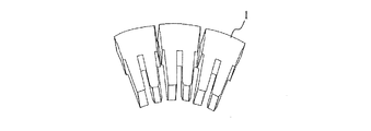
従来、回転電機のステータコアとしては例えば特許文献1に記載のものが有る。これは、図1に示す軟磁性薄板材を積層した扇状の分割コア1を図2に示すように円環状に固着させたステータコア2である。ステータコアの固着方法の一例として、ステータコア2は、図3に示すように、円環状に配列した分割コア(円環状コア)1を鋼製の円筒状のリング3に焼ばめによって挿入固定して形成する方法がある。これは、リング3を予め加熱して開口部分を拡げておき、これに円環状コア1を挿入する。そして、リング3を常温に戻すとリング3が収縮するので、この際の圧縮応力で円環状コア1が締め付けられて嵌合固定されるようになっている。
Conventionally, as a stator core of a rotating electrical machine, for example, there is one described in
しかし、上記の従来のステータコア2においては、リング3によって円環状コア1に圧縮応力が掛かると図4に一例を示すようにモータ損失が悪化する。図4は円環状コア1に圧縮応力により掛かる圧縮荷重[N]と、損失密度[kW/m]との関係を示す。回転電機の励磁周波数に相当する周波数f=100Hz及び200Hzの場合は、圧縮荷重が少しずつ増加するに従って損失密度も少しずつ大きくなり、これに応じてモータ損失が悪化している。周波数f=400Hzの場合は、圧縮荷重が0〜10Nまでの間に損失密度が顕著に大きくなっている。
However, in the above-described conventional stator core 2, when compressive stress is applied to the
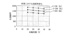
また、円環状コア1に圧縮応力が掛かると例えば図5に一例を示すように透磁率が悪くなってステータコア2に磁束が通り難くなる。図5は円環状コア1に圧縮応力により掛かる圧縮荷重[N]と、比透磁率との関係を示す。ロータ回転数に相当する周波数f=100Hz、200Hz及び400Hzの場合において、荷重が少しずつ増加するに従って比透磁率が少しずつ小さくなっている。言い換えれば透磁率が下がって磁束が通り難くなっている。この場合も、磁界を作るための電流値が増大しコイルで発生する銅損が増加してしまう。
Further, when compressive stress is applied to the
このように、リング3によって円環状コア1に圧縮応力が掛かるとステータコア2の磁気特性が悪くなって、モータ損失が大きくなる問題があった。
Thus, when compressive stress is applied to the
本発明は、このような事情に鑑みてなされたものであり、扇状の分割コアを円環状に固定する際に当該コアに圧縮荷重が掛からないようにすることができ、これによってモータ損失の悪化を防止して向上させることができる回転電機のステータコアを提供することを目的とする。 The present invention has been made in view of such circumstances, and when a fan-shaped split core is fixed in an annular shape, the core can be prevented from being subjected to a compressive load, thereby deteriorating motor loss. An object of the present invention is to provide a stator core for a rotating electrical machine that can be improved by preventing the above.
上記目的を達成するためになされた請求項1に記載の発明は、回転軸を中心に回転する円柱状のロータに所定間隔の間隙を介して配設され、扇状の積層鋼板による分割コアを円環状に配列してなる回転電機のステータコアにおいて、前記円環状に配列された分割コアは、回転軸に対して傾斜状に溶接した溶接部で一体に結合されていることを特徴とする。
この構成によれば、傾斜状に溶接した溶接部では、軸方向の磁界の発生がロータの回転に応じて時間的にずれて発生し、このため渦電流も分散されて僅かずつ流れる。これによって軸方向に沿って溶接部分がある構成と比べ、渦電流損を減少させることができ、モータ効率を向上させることができる。
In order to achieve the above-mentioned object, the invention according to
According to this configuration, in the welded portion welded in an inclined manner, the generation of the magnetic field in the axial direction is generated with a time shift in accordance with the rotation of the rotor, so that the eddy current is also dispersed and flows little by little. As a result, eddy current loss can be reduced and motor efficiency can be improved as compared with a configuration in which there is a welded portion along the axial direction.
また、円環状に配列された分割コアは、各分割コアの両側の接合辺の内、一方の接合辺の回転軸方向の一端部から他方の接合辺の回転軸方向の他端部までを溶接したことを特徴とする。
この構成によれば、従来のようにリングで円環状の分割コアを焼ばめせず、分割コア同士を溶接して全体を結合しているので、従来のようなリングによって円環状コアに圧縮応力が掛かるといったことが無くなる。従って、圧縮応力が掛かることによるステータコアの磁気特性の悪化が無くなるので、モータ損失の悪化を防止して向上させることができる。
In addition, the split cores arranged in an annular shape are welded from one end in the rotational axis direction of one joint side to the other end in the rotational axis direction of the other joint side among the joint sides on both sides of each split core. It is characterized by that.
According to this configuration, the ring-shaped split cores are not shrink-fitted with a ring as in the prior art, and the split cores are welded together so that the whole is joined. Is no longer applied. Accordingly, since the deterioration of the magnetic characteristics of the stator core due to the application of compressive stress is eliminated, the deterioration of the motor loss can be prevented and improved.
請求項2に記載の発明は、前記円環状に配列された分割コアは、前記ロータの周方向に隣り合うN極またはS極の1ピッチ分で、軸方向の一端部から他端部までを回転軸に対して傾斜状に溶接した溶接部で一体に結合されていることを特徴とする。 According to a second aspect of the present invention, the annularly arranged split cores have a pitch of N or S poles adjacent to each other in the circumferential direction of the rotor and extend from one end to the other end in the axial direction. It is characterized by being integrally connected by a welded portion welded in an inclined manner with respect to the rotating shaft.
この構成によれば、分割コアの外周面に周方向に隣り合うN極またはS極の1ピッチ分で溶接部を形成して一体化しているので、一方の極Nにおいて流れる渦電流と、他方の極Sにおいて流れる渦電流とが、溶接部を互いに逆方向に流れ、これによって互いの渦電流が相殺される。従って、渦電流が殆ど流れなくなるので、渦電流損を減少させることができ、モータ効率を向上させることができる。 According to this configuration, since the integrated to form a weld at one pitch of the N or S pole on the outer peripheral surface of the split core adjacent to each other in the circumferential direction, and the eddy current flowing in one pole N, the other The eddy currents flowing in the poles S of the other flow through the welds in opposite directions, thereby canceling out the mutual eddy currents. Therefore, since eddy current hardly flows, eddy current loss can be reduced and motor efficiency can be improved.
以下、本発明の実施形態を、図面を参照して説明する。但し、本明細書中の全図において相互に対応する部分には同一符号を付し、重複部分においては後述での説明を適時省略する。 Embodiments of the present invention will be described below with reference to the drawings. However, parts corresponding to each other in all the drawings in this specification are denoted by the same reference numerals, and description of the overlapping parts will be omitted as appropriate.
(第1実施形態)
図6は、本発明の第1実施形態に係る回転電機(モータ)の構成を示す回転軸方向の断面図である。
(First embodiment)
FIG. 6 is a cross-sectional view in the direction of the rotation axis showing the configuration of the rotating electrical machine (motor) according to the first embodiment of the present invention.
図6に示す回転電機10は、例えばハイブリッド車両や電気自動車等の車両に搭載されており、回転軸11に挿通され嵌合された円環状で薄板状の鋼板が多数積層された積層鋼板12と、この積層鋼板12の外周近傍部分に円周方向に所定間隔で軸方向に埋め込まれた永久磁石13とを有して成るロータ14を備えると共に、このロータ14の外周面に対して所定間隔の間隙を介して配置された円環状を成し、図示せぬ電力変換用のインバータに接続された三相巻線16と、この三相巻線16が巻装された積層鋼板によるステータコア17とを有して成るステータ18を備えて構成されている。
A rotating
本実施形態の特徴は、ステータコア17の結合構造にある。ステータコア17は、図7に示すように、回転軸11の軸方向Y11の断面が扇状の分割コア17a〜17jを円環状に配列し、各分割コア17a〜17jにおける軸方向Y11の両側の平行な接合辺の内、一方の接合辺の一端部から他方の接合辺の他端部までを、軸方向Y11に対して傾斜状に溶接して溶着した構造となっている。言い換えれば、各分割コア17a〜17jを軸方向Y11の両端面の一端部から当該一端部に対して斜め位置の他端部までを、符号21で示す斜めに横切る斜線状の溶接部分を有しているが、ここで、その溶接部分を斜め溶接部21と称す。
A feature of the present embodiment is a coupling structure of the
つまり、各分割コア17a〜17jは、個々が扇状の鋼板を多数積層した積層鋼板となっているので、その積層鋼板の外周面が斜め溶接部21で溶接されて一体に固着されている。更に、各分割コア17a〜17jの軸方向Y11の両側の隣接辺の一端部と他端部とが溶接されるので、隣接分割コア同士が溶着され、これによって全ての分割コア17a〜17jが円環状に一体に結合し、ステータコア17となる。
That is, each of the
このように第1実施形態の回転電機のステータコア17は、円環状に配列された分割コア17a〜17jが、各分割コア17a〜17jの両側の接合辺の内、一方の接合辺の回転軸方向Y11の一端部から他方の接合辺の他端部までを、回転軸11に対して傾斜状に溶接した斜め溶接部21で一体に結合されて成る。
As described above, in the
このような斜め溶接部21で結合されたステータコア17は、従来のようにリングで円環状の分割コアを焼ばめせず、分割コア同士を溶接して全体を結合しているので、従来のようなリングによって円環状コアに圧縮応力が掛かるといったことが無くなる。従って、圧縮応力が掛かることによるステータコアの磁気特性の悪化が無くなるので、モータ損失の悪化を防止して向上させることができる。
The
ところで、ステータ18の内側のロータ14が回転した場合を考えると、ロータ14とステータ18との間で半径方向、周方向及び軸方向Y11に磁界が発生する。ここで、分割コア17a〜17jが軸方向Y11の隣接接合辺に沿って溶接されているとすると、半径方向または周方向に発生した磁界の変化によってその溶接部分に一気に渦電流が流れる。これによって溶接部分の鉄の電気抵抗によって所定の渦電流損が発生してしまう。
By the way, when the case where the rotor 14 inside the
しかし、本実施形態では軸方向Y11に対して傾斜状の斜め溶接部21とした。この斜め溶接部21では、軸方向Y11の磁界の発生がロータ14の回転に応じて時間的にずれて発生し、このため渦電流も分散されて僅かづつ流れる。これによって上記の軸方向Y11に沿って溶接部分がある構成と比べ、渦電流損を減少させることができ、モータ効率を向上させることができる。
However, in the present embodiment, the inclined
(第2実施形態)
図8は、本発明の第2実施形態に係る回転電機のステータコアの構成を示す斜視図である。
(Second Embodiment)
FIG. 8 is a perspective view showing the configuration of the stator core of the rotating electrical machine according to the second embodiment of the present invention.
図8に示すステータコア17−1は、各分割コア17a〜17jが、符号23で示すようにロータ14の周方向に隣り合うN極またはS極の1ピッチ分で斜めに溶接された構造となっている。即ち、ロータ14に周方向に埋め込まれた永久磁石13によりN極とS極とが交互に配列された状態において、各極を半径方向に通過して磁束が最も流れるd軸(例えばN極のd軸)に対応するステータコア17−1の外周面の一端部から、そのd軸に隣接する他極Sを通過するd軸に対応するステータコア17−1の外周面の他端部に渡って斜め溶接部23が形成されている。
The stator core 17-1 shown in FIG. 8, each divided
この例では、ステータコア17−1の外周に、隣合うd軸上の一端部から他端部までN極またはS極の1ピッチ分で斜め溶接部23が形成されているとしたが、1磁極分のピッチであればd軸上間での形成でなくともよい。
In this example, the outer periphery of the stator core 17-1, was
つまり、円環状の分割コア17a〜17jの周回面に、ロータ14のN極またはS極の1ピッチ分で、軸方向Y11の一端部から他端部まで軸方向Y11に対して傾斜状に斜め溶接部23が形成されている。これによって、各分割コア17a〜17jを形成する積層鋼板の外周面が斜め溶接部23で溶接されて一体に固着される。更に、各分割コア17a〜17jの軸方向Y11の隣接辺同士も斜めに通過する斜め溶接部23で溶接されるので、全ての分割コア17a〜17jが円環状に一体に結合される。
That is, obliquely in the circumferential surface of the
このように第2実施形態の回転電機のステータコア17−1は、従来のようにリングで円環状の分割コアを焼ばめせず、分割コア17a〜17j同士を溶接して全体を結合しているので、従来のような圧縮応力が掛かるといったことが無くなる。従って、ステータコア17−1の磁気特性の悪化が無くなるので、モータ損失の悪化を防止して向上させることができる。
As described above, the stator core 17-1 of the rotating electrical machine according to the second embodiment is joined together by welding the divided
また、全ての分割コア17a〜17jを一体に結合する際に、その外周面にN極またはS極の1ピッチ分で斜めに溶接部23を形成して行っているので、一方の極Nにおいて流れる渦電流と、他方の極Sにおいて流れる渦電流とが、斜め溶接部23を互いに逆方向に流れ、これによって互いの渦電流が相殺される。従って、渦電流が殆ど流れなくなるので、渦電流損を減少させることができ、モータ効率を向上させることができる。
Moreover, all the divided
実施形態においては本発明の好適な例を示したが、実際の溶接部の傾斜角度範囲や軸方向端面における溶接開始位置が実施例と異なる場合でも本発明の意図から外れるものでは無い。 In the embodiment, a preferable example of the present invention has been shown. However, even when the actual inclination angle range of the welded portion and the welding start position on the end face in the axial direction are different from those of the embodiment, it does not depart from the intention of the present invention.
10 回転電機
11 回転軸
12 積層鋼板
13 永久磁石
14 ロータ
16 三相巻線
17,17−1 ステータコア
17a〜17j 分割コア
18 ステータ
21,23 斜め溶接部
DESCRIPTION OF
Claims (2)
前記円環状に配列された分割コアは、回転軸に対して傾斜状に溶接した溶接部で一体に結合され、
前記円環状に配列された分割コアは、各分割コアの両側の接合辺の内、一方の接合辺の回転軸方向の一端部から他方の接合辺の回転軸方向の他端部までを溶接したことを特徴とする回転電機のステータコア。
In a stator core of a rotating electrical machine that is arranged in a circular columnar rotor that rotates about a rotation axis with a gap of a predetermined interval, and in which divided cores made of fan-shaped laminated steel plates are arranged in an annular shape,
The split cores arranged in an annular shape are integrally coupled with a welded portion welded in an inclined manner with respect to the rotation axis,
The split cores arranged in an annular shape are welded from one end in the rotational axis direction of one joint side to the other end in the rotational axis direction of the other joint side among the joint sides on both sides of each split core. A stator core for a rotating electrical machine.
The split cores arranged in an annular shape are joined together by a welded portion welded from one end to the other end in the rotation axis direction for one pitch of N or S poles adjacent in the circumferential direction of the rotor. The stator core for a rotating electrical machine according to claim 1, wherein the stator core is a rotating electrical machine.
Priority Applications (2)
| Application Number | Priority Date | Filing Date | Title |
|---|---|---|---|
| JP2010088530A JP5659541B2 (en) | 2010-04-07 | 2010-04-07 | Rotating electric machine stator core |
| US13/080,904 US8410657B2 (en) | 2010-04-07 | 2011-04-06 | Mounting-structure of stator core adapted to rotating electrical machine |
Applications Claiming Priority (1)
| Application Number | Priority Date | Filing Date | Title |
|---|---|---|---|
| JP2010088530A JP5659541B2 (en) | 2010-04-07 | 2010-04-07 | Rotating electric machine stator core |
Publications (3)
| Publication Number | Publication Date |
|---|---|
| JP2011223704A JP2011223704A (en) | 2011-11-04 |
| JP2011223704A5 JP2011223704A5 (en) | 2012-09-06 |
| JP5659541B2 true JP5659541B2 (en) | 2015-01-28 |
Family
ID=44760416
Family Applications (1)
| Application Number | Title | Priority Date | Filing Date |
|---|---|---|---|
| JP2010088530A Active JP5659541B2 (en) | 2010-04-07 | 2010-04-07 | Rotating electric machine stator core |
Country Status (2)
| Country | Link |
|---|---|
| US (1) | US8410657B2 (en) |
| JP (1) | JP5659541B2 (en) |
Families Citing this family (9)
| Publication number | Priority date | Publication date | Assignee | Title |
|---|---|---|---|---|
| JP2013099047A (en) * | 2011-10-31 | 2013-05-20 | Toyota Industries Corp | Rotor of permanent magnet rotary electric machine and permanent magnet rotary electric machine |
| JP2014117030A (en) * | 2012-12-07 | 2014-06-26 | Hitachi Ltd | Axial gap polyphase motor, stator for use therein and method of manufacturing stator |
| KR101677317B1 (en) | 2013-07-03 | 2016-11-17 | 주식회사 포스코 | Method for manufacturing electrical steel sheet laminated core for reducing core loss and increasing strength and laminated core produced by the same |
| WO2016101983A1 (en) * | 2014-12-22 | 2016-06-30 | Arcelik Anonim Sirketi | Segmented stator and method of manufacturing the same |
| JP6652190B2 (en) * | 2016-03-28 | 2020-02-19 | アイシン・エィ・ダブリュ株式会社 | Method of manufacturing rotor |
| DE102020211144A1 (en) * | 2020-09-03 | 2022-03-03 | Valeo Siemens Eautomotive Germany Gmbh | Stator core, electrical machine and vehicle |
| JP2022136837A (en) * | 2021-03-08 | 2022-09-21 | 日本電産株式会社 | Stator, rotary electric machine, drive unit, and mobile object |
| WO2023238170A1 (en) * | 2022-06-06 | 2023-12-14 | 三菱電機株式会社 | Electric motor and method for manufacturing electric motor |
| DE102022127198A1 (en) | 2022-10-18 | 2024-04-18 | Schaeffler Technologies AG & Co. KG | Stator and electrical machine |
Family Cites Families (9)
| Publication number | Priority date | Publication date | Assignee | Title |
|---|---|---|---|---|
| US4114019A (en) * | 1976-12-22 | 1978-09-12 | Electric Machinery Mfg. Company | Welding of laminations of core-plated silicon steel |
| JPH09308144A (en) * | 1996-05-14 | 1997-11-28 | Matsushita Electric Ind Co Ltd | Stator of motor |
| WO1999021264A1 (en) * | 1997-10-17 | 1999-04-29 | Seiko Epson Corporation | Motor laminated core, method of manufacturing same, motor and ink jet recording device |
| JP2000278892A (en) * | 1999-03-19 | 2000-10-06 | Mitsubishi Electric Corp | Fixed core of ac generator for vehicle and manufacture of stator core thereof |
| JP4040202B2 (en) * | 1999-04-01 | 2008-01-30 | 三菱電機株式会社 | Stator core for vehicle alternator and method for manufacturing stator core for vehicle alternator |
| DE10110466A1 (en) * | 2001-03-05 | 2002-09-26 | Compact Dynamics Gmbh | Assembly of an electrical machine and electrical machine with such an assembly |
| JP2005278298A (en) * | 2004-03-24 | 2005-10-06 | Yaskawa Electric Corp | Split core, skewed split laminated core, skewed laminated annular core, split laminated core skew forming apparatus, stator and electric motor |
| WO2006120975A1 (en) * | 2005-05-06 | 2006-11-16 | Mitsuba Corporation | Motor, rotary electric machine and its stator, and method for manufacturing the stator |
| JP5126577B2 (en) | 2007-06-27 | 2013-01-23 | 株式会社デンソー | Rotating electric machine stator |
-
2010
- 2010-04-07 JP JP2010088530A patent/JP5659541B2/en active Active
-
2011
- 2011-04-06 US US13/080,904 patent/US8410657B2/en active Active
Also Published As
| Publication number | Publication date |
|---|---|
| US20110248598A1 (en) | 2011-10-13 |
| JP2011223704A (en) | 2011-11-04 |
| US8410657B2 (en) | 2013-04-02 |
Similar Documents
| Publication | Publication Date | Title |
|---|---|---|
| JP5659541B2 (en) | Rotating electric machine stator core | |
| US7514833B2 (en) | Axial gap permanent-magnet machine with reluctance poles and PM element covers | |
| JP5288724B2 (en) | Rotating electric machine rotor and rotating electric machine | |
| JP5736861B2 (en) | Rotating electrical machine rotor | |
| JP5159153B2 (en) | Rotating electric machine rotor and rotating electric machine | |
| JP6709712B2 (en) | Synchronous reluctance type rotating electric machine | |
| JP5365074B2 (en) | Axial gap type rotating electrical machine | |
| JP2011223704A5 (en) | ||
| JP2020188611A (en) | Rotor and motor having the same | |
| WO2019003560A1 (en) | Stator for dynamo-electric machine, and dynamo-electric machine | |
| JP6610418B2 (en) | Rotor, rotating electrical machine, and method of manufacturing rotor | |
| JP2009077525A (en) | Rotor for dynamo-electric machine and dynamo-electric machine | |
| JP4569839B2 (en) | AC motor | |
| JP2018026929A (en) | Electric motor | |
| JP2010004635A (en) | Field magneton, manufacturing method therefor, and rotating electrical machine | |
| JP2009077491A (en) | Stator core laminated body and electric motor | |
| JP2020156277A (en) | Stator and rotary electricity | |
| WO2022059789A1 (en) | Stator and motor | |
| JP5672149B2 (en) | Rotating electric machine rotor and rotating electric machine using the same | |
| JP4192086B2 (en) | Exciter, field machine, and electric motor using the same | |
| JP2010207021A (en) | End plate for rotor and rotary electric machine using the same | |
| US11223246B2 (en) | Stator | |
| JP6536421B2 (en) | Electric rotating machine | |
| JP7150171B2 (en) | Rotating electric machine stator, terminal block and rotating electric machine | |
| JP5175126B2 (en) | Rotating electrical machine rotor and rotating electrical machine |
Legal Events
| Date | Code | Title | Description |
|---|---|---|---|
| A521 | Request for written amendment filed |
Free format text: JAPANESE INTERMEDIATE CODE: A523 Effective date: 20120719 |
|
| A621 | Written request for application examination |
Free format text: JAPANESE INTERMEDIATE CODE: A621 Effective date: 20120719 |
|
| A977 | Report on retrieval |
Free format text: JAPANESE INTERMEDIATE CODE: A971007 Effective date: 20131114 |
|
| A131 | Notification of reasons for refusal |
Free format text: JAPANESE INTERMEDIATE CODE: A131 Effective date: 20131121 |
|
| A521 | Request for written amendment filed |
Free format text: JAPANESE INTERMEDIATE CODE: A523 Effective date: 20140109 |
|
| A02 | Decision of refusal |
Free format text: JAPANESE INTERMEDIATE CODE: A02 Effective date: 20140603 |
|
| A521 | Request for written amendment filed |
Free format text: JAPANESE INTERMEDIATE CODE: A523 Effective date: 20140901 |
|
| A911 | Transfer to examiner for re-examination before appeal (zenchi) |
Free format text: JAPANESE INTERMEDIATE CODE: A911 Effective date: 20140909 |
|
| TRDD | Decision of grant or rejection written | ||
| A01 | Written decision to grant a patent or to grant a registration (utility model) |
Free format text: JAPANESE INTERMEDIATE CODE: A01 Effective date: 20141104 |
|
| A61 | First payment of annual fees (during grant procedure) |
Free format text: JAPANESE INTERMEDIATE CODE: A61 Effective date: 20141117 |
|
| R151 | Written notification of patent or utility model registration |
Ref document number: 5659541 Country of ref document: JP Free format text: JAPANESE INTERMEDIATE CODE: R151 |
|
| R250 | Receipt of annual fees |
Free format text: JAPANESE INTERMEDIATE CODE: R250 |
|
| R250 | Receipt of annual fees |
Free format text: JAPANESE INTERMEDIATE CODE: R250 |
|
| R250 | Receipt of annual fees |
Free format text: JAPANESE INTERMEDIATE CODE: R250 |
|
| R250 | Receipt of annual fees |
Free format text: JAPANESE INTERMEDIATE CODE: R250 |
|
| R250 | Receipt of annual fees |
Free format text: JAPANESE INTERMEDIATE CODE: R250 |
|
| R250 | Receipt of annual fees |
Free format text: JAPANESE INTERMEDIATE CODE: R250 |
|
| R250 | Receipt of annual fees |
Free format text: JAPANESE INTERMEDIATE CODE: R250 |