JP2010004635A - Field magneton, manufacturing method therefor, and rotating electrical machine - Google Patents
Field magneton, manufacturing method therefor, and rotating electrical machine Download PDFInfo
- Publication number
- JP2010004635A JP2010004635A JP2008160261A JP2008160261A JP2010004635A JP 2010004635 A JP2010004635 A JP 2010004635A JP 2008160261 A JP2008160261 A JP 2008160261A JP 2008160261 A JP2008160261 A JP 2008160261A JP 2010004635 A JP2010004635 A JP 2010004635A
- Authority
- JP
- Japan
- Prior art keywords
- field element
- magnetic body
- magnetic
- teeth
- permanent magnet
- Prior art date
- Legal status (The legal status is an assumption and is not a legal conclusion. Google has not performed a legal analysis and makes no representation as to the accuracy of the status listed.)
- Pending
Links
Images


Landscapes
- Iron Core Of Rotating Electric Machines (AREA)
- Manufacture Of Motors, Generators (AREA)
- Permanent Magnet Type Synchronous Machine (AREA)
Abstract
Description
この発明は界磁子に関し、特にアキシャルギャップ型回転電機に採用される界磁子の構成に関する。 The present invention relates to a field element, and more particularly to a configuration of a field element employed in an axial gap type rotating electrical machine.
薄型化しても高出力や高効率が実現できる、アキシャルギャップ型モータが近年注目されている。しかし、高出力であるために、電流を多く流せば減磁界も増大する。よって界磁子に磁石を有する場合、磁石を電機子側から覆う磁性体を設けることがある(例えば特許文献1)。 In recent years, axial gap type motors that can achieve high output and high efficiency even if they are made thinner have attracted attention. However, since the power is high, the demagnetizing field increases if a large amount of current is passed. Therefore, when a field element has a magnet, a magnetic body that covers the magnet from the armature side may be provided (for example, Patent Document 1).
この磁性体を、従来のラジアルギャップ型モータのヨークのように、電磁鋼板を回転軸に平行な方向(以下「回転軸方向」と称す)に沿って積層して形成することは望ましくない。当該磁性体を通る界磁磁束は、回転軸を中心とした周方向の成分を有するものの、電機子へと向かう回転軸方向の成分を主としている。そして回転軸方向に沿って積層された電磁鋼板は、界磁磁束の回転軸方向成分に対して大きな磁気抵抗を与えることになる。 It is not desirable to form this magnetic body by laminating electromagnetic steel sheets along a direction parallel to the rotation axis (hereinafter referred to as “rotation axis direction”) like a yoke of a conventional radial gap motor. The field magnetic flux passing through the magnetic body mainly has a component in the rotation axis direction toward the armature, although it has a component in the circumferential direction around the rotation axis. And the magnetic steel sheet laminated | stacked along the rotating shaft direction gives a big magnetic resistance with respect to the rotating shaft direction component of a field magnetic flux.
このような問題を解決する方法として、たとえば当該磁性体に圧粉鉄心を用いることが考えられる。しかし圧粉鉄心は透磁率が低い。また、他の構造体と当該磁性体とを接合するのに採用される手法では、焼きばめや圧入など強い応力がかかったり、溶接など入熱が大きかったりするため、圧粉鉄心を当該磁性体に用いることは適していない。 As a method for solving such a problem, for example, it is conceivable to use a dust core for the magnetic material. However, the dust core has low permeability. In addition, in the method adopted to join other structures to the magnetic body, a strong stress such as shrink fitting or press fitting is applied, or heat input such as welding is large. Not suitable for use on the body.
そこで本発明においては、アキシャルギャップ型モータにおける磁束の流れに適応して、透磁率が高く、また、鉄損の少ない界磁子(ひいては回転電機)を、簡単な方法にて提供するものである。 Therefore, in the present invention, a field element (and consequently a rotating electrical machine) having high magnetic permeability and low iron loss is provided by a simple method in conformity with the flow of magnetic flux in an axial gap type motor. .
この発明にかかる界磁子の第1の態様は、回転軸(50a)の周囲で回転する界磁子(20)であって、前記回転軸の周囲で周方向に複数個配置され、その各々が前記回転軸に沿った方向である回転軸方向の一方側に呈する第1磁極面と、前記回転軸方向の他方側に呈する第2磁極面とを有する永久磁石(22)と、前記第1磁極面を前記一方側から覆って設けられた第1の磁性体(24)とを備える。前記第1の磁性体は、前記回転軸に沿って見て前記回転軸に対して凹となる弧状の鋼板(91)の複数を有し、前記鋼板は、その属する前記第1の磁性体が設けられた位置において前記回転軸に垂直に積層される。 A first aspect of the field element according to the present invention is a field element (20) that rotates around a rotation axis (50a), and a plurality of field elements are arranged in the circumferential direction around the rotation axis, A permanent magnet (22) having a first magnetic pole surface that is present on one side in the direction of the rotational axis, which is a direction along the rotational axis, and a second magnetic pole surface that is present on the other side in the direction of the rotational axis, And a first magnetic body (24) provided so as to cover the magnetic pole surface from the one side. The first magnetic body has a plurality of arc-shaped steel plates (91) that are concave with respect to the rotation axis when viewed along the rotation axis, and the steel plate includes the first magnetic body to which the first magnetic body belongs. It is laminated perpendicularly to the rotation axis at the provided position.
この発明にかかる界磁子の第2の態様は、その第1の態様であって、前記第1の磁性体(24)の前記永久磁石(22)側の外径(ro3;ro4)は、前記永久磁石の前記磁性体側の外径(do3;do4)に対し、前記鋼板(91)の厚み(t)の2倍以上大きい。 A second aspect of the field element according to the present invention is the first aspect, wherein an outer diameter (ro3; ro4) of the first magnetic body (24) on the permanent magnet (22) side is: It is more than twice the thickness (t) of the steel plate (91) with respect to the outer diameter (do3; do4) of the permanent magnet on the magnetic body side.
この発明にかかる界磁子の第3の態様は、その第1の態様であって、前記第1の磁性体(24)の前記永久磁石(22)側の外径(ro3;ro4)は、前記永久磁石の前記磁性体側の外径(do3;do4)に対し、前記鋼板(91)の厚みの3倍以上大きい。 A third aspect of the field element according to the present invention is the first aspect, and the outer diameter (ro3; ro4) of the first magnetic body (24) on the permanent magnet (22) side is: It is more than 3 times the thickness of the steel plate (91) with respect to the outer diameter (do3; do4) on the magnetic body side of the permanent magnet.
この発明にかかる界磁子の第4の態様は、その第1乃至第3の態様のいずれかであって、前記第1の磁性体(24)の前記永久磁石(22)側の内径(ri3;ri4)は、前記永久磁石の前記磁性体側の内径(di3;di4)に対し、前記鋼板(91)の厚み(t)の2倍以上小さい。 A field element according to a fourth aspect of the present invention is any one of the first to third aspects, wherein the inner diameter (ri3) of the first magnetic body (24) on the permanent magnet (22) side. Ri4) is smaller than twice the thickness (t) of the steel plate (91) with respect to the inner diameter (di3; di4) of the permanent magnet on the magnetic body side.
この発明にかかる界磁子の第5の態様は、その第1乃至第3の態様のいずれかであって、前記第1の磁性体(24)の前記永久磁石(22)側の内径(ri3;ri4)は、前記永久磁石の前記磁性体側の内径(di3;di4)に対し、前記鋼板(91)の厚みの3倍以上小さい。 A fifth aspect of the field element according to the present invention is any one of the first to third aspects, wherein an inner diameter (ri3) of the first magnetic body (24) on the permanent magnet (22) side. Ri4) is smaller than the inner diameter (di3; di4) of the permanent magnet on the magnetic body side by three times or more the thickness of the steel plate (91).
この発明にかかる界磁子の第6の態様は、その第1乃至第5の態様のいずれかであって、前記鋼板(91)の前記回転軸に垂直な面内での曲率半径(ri0;ro0)は、その前記回転軸(50a)からの距離(ri1;ro1)よりも小さい。 A field element according to a sixth aspect of the present invention is any one of the first to fifth aspects, wherein the steel plate (91) has a radius of curvature (ri0; in a plane perpendicular to the rotation axis). ro0) is smaller than the distance (ri1; ro1) from the rotation axis (50a).
この発明にかかる界磁子の第7の態様は、その第1乃至第6の態様のいずれかであって、前記回転軸(50a)の周囲で前記第1の磁性体(24)と前記周方向に交互に配置される第2の磁性体(29)を更に備える。 A seventh aspect of the field element according to the present invention is any one of the first to sixth aspects, wherein the first magnetic body (24) and the circumference are arranged around the rotating shaft (50a). Further provided are second magnetic bodies (29) arranged alternately in the direction.
この発明にかかる界磁子の第8の態様は、その第7の態様であって、前記第2の磁性体(29)は積層された複数の鋼板を有する。 The 8th aspect of the field element concerning this invention is the 7th aspect, Comprising: The said 2nd magnetic body (29) has a some steel plate laminated | stacked.
この発明にかかる回転電機の第1の態様は、この発明にかかる界磁子の第1乃至第8の態様のいずれかと、電機子巻線(36)が巻回されて前記回転軸(50a)の周囲に複数個配置されたティース(38)を有し、前記ティースを前記界磁子へと前記一方側から対向させる電機子(30)とを備える回転電機(10)である。そして前記磁性体(24)の前記ティース側の外径(ro1;ro2)は、前記ティースの前記磁性体側の外径(Ro1;Ro2)に対し、前記鋼板(91)の厚み(t)の2倍以上大きい。 According to a first aspect of the rotating electrical machine of the present invention, any one of the first to eighth aspects of the field element according to the present invention and the armature winding (36) are wound around the rotating shaft (50a). A rotating electric machine (10) having a plurality of teeth (38) arranged around the armature and including an armature (30) that makes the teeth face the field element from the one side. The outer diameter (ro1; ro2) on the teeth side of the magnetic body (24) is 2 of the thickness (t) of the steel plate (91) with respect to the outer diameter (Ro1; Ro2) on the magnetic body side of the teeth. More than double.
この発明にかかる回転電機の第2の態様は、その第1の態様であって、前記磁性体(24)の前記ティース側の外径(ro1;ro2)は、前記ティースの前記磁性体側の外径(Ro1;Ro2)に対し、前記鋼板(91)の厚み(t)の3倍以上大きい。 A second aspect of the rotating electrical machine according to the present invention is the first aspect, wherein an outer diameter (ro1; ro2) of the magnetic body (24) on an outer side of the tooth on the magnetic body side is set. The diameter (Ro1; Ro2) is at least three times larger than the thickness (t) of the steel plate (91).
この発明にかかる回転電機の第3の態様は、この発明にかかる界磁子の第1乃至第8の態様のいずれかと、電機子巻線(36)が巻回されて前記回転軸(50a)の周囲に複数個配置されたティース(38)を有し、前記ティースを前記界磁子へと前記一方側から対向させる電機子(30)とを備える回転電機(10)である。そして前記磁性体(24)の前記ティース側の内径(ri1;ri2)は、前記ティースの前記磁性体側の内径(Ri1;Ri2)に対し、前記鋼板(91)の厚み(t)の2倍以上小さい。 According to a third aspect of the rotating electrical machine of the present invention, any one of the first to eighth aspects of the field element according to the present invention and the armature winding (36) are wound around the rotating shaft (50a). A rotating electric machine (10) having a plurality of teeth (38) arranged around the armature and including an armature (30) that makes the teeth face the field element from the one side. And the inner diameter (ri1; ri2) on the teeth side of the magnetic body (24) is at least twice the thickness (t) of the steel plate (91) with respect to the inner diameter (Ri1; Ri2) on the magnetic body side of the teeth. small.
この発明にかかる回転電機の第4の態様は、その第3の態様であって、前記磁性体(24)の前記ティース側の内径(ri1;ri2)は、前記ティースの前記磁性体側の内径(Ri1;Ri2)に対し、前記鋼板(91)の厚み(t)の3倍以上小さい。 4th aspect of the rotary electric machine concerning this invention is the 3rd aspect, Comprising: The internal diameter (ri1; ri2) of the said teeth side of the said magnetic body (24) is the internal diameter (ri) of the said magnetic body of the said teeth ( The thickness (t) of the steel plate (91) is at least three times smaller than Ri1; Ri2).
この発明にかかる回転電機の第5の態様は、その第1乃至第4の態様のいずれかであって、前記ティース(38)は鋼板を巻いて形成した円環状の巻きコア以外の構造を採る。 A fifth aspect of the rotating electrical machine according to the present invention is any one of the first to fourth aspects, and the teeth (38) adopt a structure other than an annular wound core formed by winding a steel plate. .
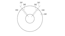
この発明にかかる界磁子の製造方法の第1の態様は、この発明にかかる界磁子の第6の態様を製造する方法であって、(a)前記鋼板(91)を巻いて形成した円環状の巻きコア(240)を形成する工程と、(b)前記巻きコアを径方向に沿った切断位置(241)で切断して前記第1磁性体を切り出す工程とを備える。 A first aspect of a method for manufacturing a field element according to the present invention is a method for manufacturing a sixth aspect of the field element according to the present invention, and is formed by winding (a) the steel plate (91). Forming an annular winding core (240); and (b) cutting the winding core at a cutting position (241) along a radial direction to cut out the first magnetic body.
この発明にかかる界磁子の製造方法の第2の態様は、その第1の態様であって、(c)前記工程(a)後、前記工程(b)前に、前記切断位置(241)の前記周方向における両側の位置(242)において前記鋼板(91)同士を溶接する工程を更に備える。 The 2nd aspect of the manufacturing method of the field element concerning this invention is the 1st aspect, Comprising: (c) The said cutting position (241) after the said process (a) and before the said process (b). The method further comprises a step of welding the steel plates (91) at positions (242) on both sides in the circumferential direction.
この発明にかかる界磁子の製造方法の第3の態様は、その第2の態様であって、前記工程(c)において溶接される前記位置(242)は、前記永久磁石(22)よりも前記周方向において外側にある。 The 3rd aspect of the manufacturing method of the field element concerning this invention is the 2nd aspect, Comprising: The said position (242) welded in the said process (c) is more than the said permanent magnet (22). It is outside in the circumferential direction.
この発明にかかる界磁子の製造方法の第4の態様は、その第1の態様であって、(c)前記工程(a)後、前記工程(b)前に、前記鋼板(91)同士を絶縁体で固着する工程を更に備える。 The 4th aspect of the manufacturing method of the field element concerning this invention is the 1st aspect, Comprising: The said steel plates (91) are after (c) said process (a) and before the said process (b). The method further includes the step of adhering with an insulator.
この発明にかかる界磁子の製造方法の第5の態様は、この発明にかかる界磁子の第8の態様を製造する方法であって、(a)前記鋼板(91)を巻いて形成した円環状の巻きコア(240)を形成する工程と、(b)前記巻きコアを放射状の切断位置(243)で切断し、前記第1磁性体と前記第2磁性体とを切り出す工程とを備える。 A fifth aspect of the method for manufacturing a field element according to the present invention is a method for manufacturing the eighth aspect of the field element according to the present invention, and is formed by winding (a) the steel plate (91). Forming an annular winding core (240); and (b) cutting the winding core at a radial cutting position (243) to cut out the first magnetic body and the second magnetic body. .
この発明にかかる界磁子の製造方法の第6の態様は、その第5の態様であって、前記鋼板の巻き端は前記第1磁性体に含められる。 A sixth aspect of the method for manufacturing a field element according to the present invention is the fifth aspect, and a winding end of the steel plate is included in the first magnetic body.
この発明にかかる界磁子の第1の態様によれば、当該界磁子の一方側に電機子を配置して回転電機を構成することができる。しかも永久磁石は当該電機子から供給される磁界から第1磁性体によって遮蔽されるので、当該永久磁石の減磁を低減できる。更に第1磁性体は弧状の鋼板が積層されているので、鋼板を巻いて形成した円環状の巻きコアを分断して容易に作製できる。 According to the first aspect of the field element according to the present invention, the rotating electric machine can be configured by arranging the armature on one side of the field element. In addition, since the permanent magnet is shielded from the magnetic field supplied from the armature by the first magnetic body, demagnetization of the permanent magnet can be reduced. Furthermore, since the arcuate steel plate is laminated | stacked on the 1st magnetic body, it can manufacture easily by parting the annular | circular shaped winding core formed by winding a steel plate.
この発明にかかる界磁子の第2の態様及び第4の態様並びに回転電機の第1の態様及び第3の態様によれば、円環状の巻きコアの径方向端部においては磁気抵抗が大きくなる傾向がある。これは鋼板の不連続性、あるいは巻きコアから鋼板が剥がれないように止める溶接による歪みに起因する。当該界磁子によれば、このような磁気抵抗が大きくなる位置を、磁束が通ることを回避する。 According to the second and fourth aspects of the field element and the first and third aspects of the rotating electric machine according to the present invention, the magnetic resistance is large at the radial end of the annular winding core. Tend to be. This is due to the discontinuity of the steel sheet or the distortion caused by welding to prevent the steel sheet from peeling off from the wound core. According to the field element, the magnetic flux is prevented from passing through the position where the magnetic resistance is increased.
この発明にかかる界磁子の第3の態様及び第5の態様並びに回転電機の第2の態様及び第4の態様によれば、円環状の巻きコアの鋼板の値の公差は板厚程度となるので、円環状の巻きコアの径方向端部における磁気抵抗が大きい位置を、磁束が通ることを回避する効果が高い。 According to the third and fifth aspects of the field element according to the present invention and the second and fourth aspects of the rotating electric machine, the tolerance of the value of the steel plate of the annular winding core is about the plate thickness. Therefore, the effect of preventing the magnetic flux from passing through the position where the magnetic resistance is large at the radial end of the annular winding core is high.
この発明にかかる界磁子の第6の態様及び界磁子の製造方法の第1の態様によれば、円環状の巻きコアを分断して第1の磁性体を容易に作製できる。 According to the sixth aspect of the field element and the first aspect of the method of manufacturing a field element according to the present invention, the first magnetic body can be easily manufactured by dividing the annular winding core.
この発明にかかる界磁子の第7の態様によれば、いわゆるq軸インダクタンスを高め、リラクタンストルクを利用するモータの実現に資する。 According to the seventh aspect of the field element of the present invention, so-called q-axis inductance is increased, which contributes to the realization of a motor that uses reluctance torque.
この発明にかかる界磁子の第8の態様及び界磁子の製造方法の第5の態様によれば、第2の磁性体を第1の磁性体と同じ鋼板を用いて製造することで材料の無駄を低減する。 According to the eighth aspect of the field element and the fifth aspect of the method of manufacturing a field element according to the present invention, the second magnetic body is manufactured by using the same steel plate as the first magnetic body. Reduce waste.
この発明にかかる回転電機の第5の態様によれば、ティースと第1の磁性体との間の位置関係を複雑にしない。 According to the fifth aspect of the rotating electrical machine of the present invention, the positional relationship between the teeth and the first magnetic body is not complicated.
この発明にかかる界磁子の製造方法の第2の態様及び第4の態様によれば、巻きコアを切断した後に鋼板が剥がれることを防止する。 According to the 2nd aspect and the 4th aspect of the manufacturing method of the field element concerning this invention, it is prevented that a steel plate peels after cut | disconnecting a winding core.
この発明にかかる界磁子の製造方法の第13態様によれば、溶接に起因して溶接位置で第1磁性体に変形が生じても、当該変形は第1磁性体が永久磁石を覆う邪魔にならない。 According to the thirteenth aspect of the field element manufacturing method of the present invention, even if the first magnetic body is deformed at the welding position due to welding, the deformation is an obstacle to the first magnetic body covering the permanent magnet. do not become.
この発明にかかる界磁子の製造方法の第6の態様によれば、第1磁性体と比較して細くなる第2磁性体の、径方向端部における鋼板の強度不足を防止する。 According to the sixth aspect of the field element manufacturing method of the present invention, the strength of the steel plate at the radial end of the second magnetic body that is thinner than the first magnetic body is prevented.
本発明が適用される回転電機の構成.
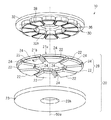
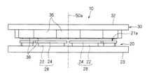
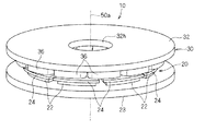
図1は本発明を適用可能なアキシャルギャップ型回転電機10を示す分解斜視図であり、回転軸50aに沿って分解して構成を示している。図2は同回転電機を示す側面図であり、図3は同回転電機を示す斜視図であり、図4は同回転電機を概念的に示す断面図である。図2〜図4は回転軸50a方向に分解して描いてはいない。ここではアキシャルギャップ型回転電機10として、3相交流で駆動される構成を例示した。アキシャルギャップ型回転電機10は、例えば冷媒を圧縮する圧縮機の駆動源として採用される。
Configuration of rotating electrical machine to which the present invention is applied.
FIG. 1 is an exploded perspective view showing an axial gap type rotating
アキシャルギャップ型回転電機10は、回転子として機能する界磁子20と、固定子として機能する電機子30とを備えている。回転子20は略円盤状に形成されており、電機子30も略円盤状に形成されている。
The axial gap type rotating
図4を参照して、界磁子20はシャフト50に固定され、回転軸50a周りに回転自在に配設されている。図1〜図3ではシャフト50の図示を省略している。
Referring to FIG. 4,
界磁子20は回転軸50aの周囲に配置される界磁発生部28を有しており、界磁発生部28の各々は、電機子30に対向する磁極面21aを呈している。
The
具体的には界磁子20は、回転軸50a周りに間隔をあけて複数の永久磁石22を有している。各永久磁石22は、回転軸50a周りのドーナツ板状部材を複数(ここでは8つ)に分割した形状、即ち、回転軸50a周りに延びる弧状かつ帯状の板形状に形成されている。各永久磁石22は、回転軸50aに沿った方向、即ち、永久磁石22の厚み方向に着磁されている。これらの永久磁石22は、回転軸50aの周囲で環状かつ交互の磁極を呈するように配設されている。
Specifically, the
電機子30は、回転軸50a方向において界磁子20に対してギャップを隔てて対向するように配設されている。電機子30は図示省略のケーシング等に固定されている。
The
電機子30は、バックヨーク32と、複数のティース34と、複数のコイル36とを有している。
The
バックヨーク32は、磁性体によって構成されており、略中央部に孔部32hが形成された略円盤板状に形成されている。孔部32hは、シャフト50の端部が、電機子30の非貫通な位置に設けられている場合は必須ではない。バックヨーク32は、圧粉鉄心、積層された電磁鋼板等のいずれで形成されていてもよい。このバックヨーク32は、ティース34を、上記界磁子20とは反対側で支持している。
The
各ティース34は、バックヨーク32の界磁子20側の面に、回転軸50a周りの周方向に沿って間隔をあけて環状に配設されている。各ティース34は、回転軸50aと略直交する平面において、2等辺三角形状の各頂点を丸めた形状を有する板状に形成されており、回転軸50aから外方向に向けて順次幅広になる姿勢で配設されている。このティース34は、圧粉鉄心、積層電磁鋼板等のいずれで形成されていてもよい。なお、互いに周方向に隣接する各ティース34間は、略等間隔である。
The
各コイル36は、各ティース34に巻回されている。なお、各コイル36同士を結線する渡り配線部37は、第1バックヨーク32の略中央部であって界磁子20側の部分に設けられている。また、この渡り配線部37からの外部配線37aは、孔部32hを通って外部に引き出されている。
Each
本願で特に断らない限り、コイルは、これを構成する導線の一本一本を指すのではなく、導線が一纏まりに巻回された態様を指す。これは図面においても同様である。また、巻き始め及び巻き終わりの引き出し線、及びそれらの結線も図面においては省略した。 Unless otherwise specified in the present application, the coil does not indicate each one of the conductive wires constituting the coil, but indicates an aspect in which the conductive wires are wound together. The same applies to the drawings. In addition, the drawing lines at the start and end of winding and their connection are also omitted in the drawings.
シャフト50は界磁子20を回転自在に支持しており、電機子30に達しない程度の長さに形成されているため、バックヨーク32の略中央部であって界磁子20側の部分に結線用の空間を設けることができる。
Since the
なお、各コイル36同士を結線する渡り配線部37は、各ティース34及びコイル36の外周側に設けられてもよく、この渡り配線部37からの外部配線37aも、バックヨーク32の外側または、バックヨーク32の外側に設けられた切り欠き等を通して外部に引き出されてもよい。
In addition, the
電機子30では、各ティース34の界磁子20側の面に幅広磁心38がそれぞれ設けられている。各幅広磁心38は、回転軸50aと略直交する平面において、ティース34よりも大きな広がりを有する板状に形成されている。
In the
幅広磁心38は、電機子30と界磁子20との対向面積を増す機能を果す。よって界磁子20と電機子30との間で、磁束密度の向上を図ることができる。また幅広磁心38は、界磁子20に対する電機子30の平面度を高めることにも資するので、界磁子20と電機子30との間の実質的なギャップ長をより小さくできる。但し各幅広磁心38は必ずしも必須ではないし、幅広磁心38がティース34と一体化されていてもよい。
The wide
ここでは各幅広磁心38はティース34毎に分離して設けられている。この態様の他、電機子30の内周側と外周側で薄肉の連結部により連結されることにより、全ての幅広磁心38を一体物として取扱ってもよい。もっとも、当該連結部は、各幅広磁心38間で容易に磁気飽和するように、薄肉に仕上げる等、十分に断面積が小さくなるように形成されている。つまり連結部38によって機構的には連結されているものの、各幅広磁心38は磁気的には実質的に分離されるのである。
Here, each wide
負荷が電機子30側に設けられる場合、シャフト50が電機子30を貫通すべく、電機子30の孔部32hはシャフト50の外形よりも大きく設定される。また渡り配線部37の占める位置がシャフト50の占める位置と干渉しないように、渡り配線は電機子30の外周側に配置することが望ましい。
When the load is provided on the
各永久磁石22の電機子30側には、磁性体たる回転子磁心24が設けられている。各回転子磁心24は、各永久磁石22の形状に対応する弧状かつ帯状の板形状に形成されており、永久磁石22の一方面に重ね合せ状に配設されている。永久磁石22の電機子30側の磁極面は、回転子磁心24によって実質的に電機子30側に移動するので、永久磁石22と回転子磁心24とが相まって界磁発生部28を構成していると把握できる。つまり回転子磁心24の電機子30側が磁極面21aを呈していることになる。
On the
界磁子20はバックヨーク23をも有しており、この上で各永久磁石22及び各回転子磁心24が上記配設形態で保持される。バックヨーク23は、永久磁石22の電機子30とは反対側の磁極面21bを磁気的に連結する。
The
バックヨーク23は孔23hを有しており、これにシャフト50が貫通して固定されている。図1〜図3ではシャフト50の図示を省略している。
The
電機子30からの外部磁界によって界磁子20に減磁界が作用した場合に、各回転子磁心24によって、各永久磁石22に作用する減磁界の影響を緩和し、もって、各永久磁石22が減磁するのを防止している。永久磁石22と回転子磁心24とは例えば接着剤で固着される。
When a demagnetizing field acts on the
第1の実施の形態.
本実施の形態では回転子磁心24の構成及び製造方法の好ましい態様について説明する。
First embodiment.
In the present embodiment, a configuration of the rotor
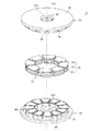
図5は回転軸50aの周囲に配置された回転子磁心24のみを取り出して示す斜視図である。回転子磁心24は、回転軸50aに沿って見て、回転軸50aに対して凹となる、弧状の電磁鋼板の複数を有している。そしてこれらの電磁鋼板は、その属する回転子磁心24が設けられた位置において回転軸50aに垂直に積層される。
FIG. 5 is a perspective view showing only the rotor
これは次の理由による。つまり回転子磁心24を通る界磁磁束は、回転軸50aを中心とした周方向の成分と、電機子10(図1参照)へと向かう回転軸方向の成分とを有している。よってこれらの成分に対する磁気抵抗を小さくするためには、回転子磁心24は回転軸50aに対する周方向及び回転軸方向の両方に延在する面において磁気障壁を有していない事が望ましい。よって透磁率の高い電磁鋼板を用い、かつ鉄損が小さな界磁子を得ることができる。また、一般的に、ティース34一つ当たりに比べて、回転子磁心24一つ当たりの中心角は大きい。従って、あるティース34から回転子磁心24を経由して、永久磁石22を通ることなく他のティース34へと戻る磁束が存在する。そして平板の電磁鋼板を積層して回転子磁心24を形成すると、当該磁束は電磁鋼板の積層方向を通ることになり、渦電流損が増大する。しかしながら、かかる渦電流損は、弧状の電磁鋼板を積層することによって回避できる。
This is due to the following reason. That is, the field magnetic flux passing through the rotor
他方、例えば、PWMインバータ駆動によって電機子30が発生させるキャリア高周波数成分の磁束は、永久磁石22まで作用し難く、その磁束による渦電流は表皮効果によって回転子磁心24の表面近傍で発生し易い。電機子30から界磁子20へと向かう磁束は回転軸方向に主たる成分を有しており、当該磁束によって回転子磁心24に発生する渦電流は回転軸方向に垂直な面内に発生することになる。しかし、回転子磁心24において電磁鋼板は径方向に積層されているため、回転子磁心24は径方向に大きな電気抵抗を有しており、そのような高周波数成分の渦電流を有効に減少させることができる。永久磁石の渦電流損の低減は鉄損の低減に加え、ネオジム系の磁石など高温で減磁する材料を用いた場合における、永久磁石の発熱による熱減磁を防止できるという効果を有する。
On the other hand, for example, the magnetic flux of the carrier high frequency component generated by the
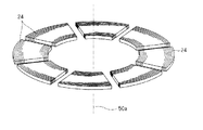
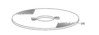
また、回転子磁心24は弧状の電磁鋼板が積層されているので、電磁鋼板を巻回して形成した円環状の巻きコアを分断して容易に作製できる。図6に当該巻きコア240の斜視図を、図7に平面図を、それぞれ示す。当該平面図は、巻きコア240を分断して得られる回転子磁心24が環状に配置される中心となる回転軸50a(図5参照)に垂直な面を示す。ここでは簡単のために電磁鋼板が巻回されている様子は図示していない。
Further, since the rotor
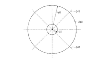
図7において、巻きコア240は、その中心から内周までの距離(即ち内径)ri0と、その中心から外周までの距離(即ち外径)ro0とによって形状が定まる円環として表される。回転子磁心24の製作には、まず、このように電磁鋼板を巻いて形成した円環状の巻きコア240を形成する。その後、巻きコア240を径方向に沿った切断位置241で切断して回転子磁心24を切り出す。よって回転子磁心24の内周端及び外周端は、それぞれ曲率半径ri0,ro0を有する。
In FIG. 7, the
図8は回転子磁心24の配置を示す平面図であり、図5に示された構造を回転軸50aに沿って見た図に相当する。巻きコア240から切り出された回転子磁心24は、巻きコア240の外側へと径方向にずれて配置される。よって回転子磁心24の内径、即ち回転軸50aから内周端までの距離ri1は、内周端における回転子磁心24の曲率半径ri0よりも大きい。同様にして、回転子磁心24の外径、即ち回転軸50aから外周端までの距離ro1は、外周端における回転子磁心24の曲率半径ro0よりも大きい。
FIG. 8 is a plan view showing the arrangement of the rotor
上述のように、巻きコア240、及びこれから切り出された回転子磁心24は、径方向に積層された電磁鋼板で形成されるので、回転軸に垂直な面内での電磁鋼板の曲率半径は、回転軸50aからの距離よりも小さいことになる。以上のように円環状の巻きコア240を分断して回転子磁心24を容易に作製できる。
As described above, the winding
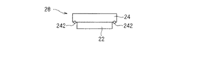
図9は回転子磁心24を巻きコア240から切り出すときの、好ましい工程を説明する平面図であり、図7に相当する平面を示している。まず鋼板を巻いて円環状の巻きコア240を形成する。そして巻きコア240から回転子磁心24を切り出す前に、切断位置241の周方向における両側の位置(以下「溶接位置」)242において電磁鋼板同士を溶接することが望ましい。巻きコア240を切断した後に電磁鋼板同士が剥がれることを防止するためである。図10は溶接位置242において溶接された回転子磁心24の一つを示す平面図である。
FIG. 9 is a plan view for explaining a preferable process when the rotor
図11は界磁発生部28の構成を示す側面図であり、径方向に沿って見ている。当該構成において、溶接位置242は永久磁石22よりも周方向において外側にある。これは溶接に起因して溶接位置242で回転子磁心24に変形が生じても、当該変形は回転子磁心24が永久磁石22を覆う邪魔にならない点で好ましい。
FIG. 11 is a side view showing the configuration of the
なお、巻きコア240を形成後、回転子磁心24を切り出す前に、積層された電磁鋼板同士を固着してもよい。たとえば電着塗装や粉体塗装してもよい。あるいは比較的粘度の小さいワニスを含浸、具体的には積層された電磁鋼板の間に浸透させてコーティングを行っても良い。このような電着塗装材料、粉体塗装材料、コーティング材としては、渦電流の低減の観点からは絶縁体が望ましい。
In addition, after forming the winding
第2の実施の形態.
本実施の形態では、回転磁心24の内径や外径の、永久磁石22や電機子30の寸法との好ましい関係について説明する。
Second embodiment.
In the present embodiment, a preferable relationship between the inner diameter and outer diameter of the rotating
図12は、巻きコア240を形成する場合に必要な工程を示す図であり、電磁鋼板91を巻回する軸方向に沿って見た平面図である。
FIG. 12 is a view showing the steps necessary for forming the winding
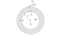
電磁鋼板91を渦巻き状に積層するためには、軸Qを中心とした半径riの円筒90に電磁鋼板91を巻き付けていく工程が必要である。即ち巻きコア240は最内周となる位置から外側へと順次に形成されることになる。電磁鋼板91を巻きコア240の最外周となる位置から順に内側へと巻き込んで積層する工程は大きな困難を伴うからである。
In order to stack the
そして上記の工程を実施すれば、円筒90に最も近い電磁鋼板91が円筒90をほぼ一周して巻回することで第1層を形成した後、円筒90とは反対側から第1層に電磁鋼板91が更に巻回されて第2層を形成することになる。
When the above process is performed, the
この第2層の形成においては、円筒90から見て第1層の端部に乗り上げる態様で電磁鋼板91が巻回される。つまり、電磁鋼板91が第1層から第2層へと向かう位置において、電磁鋼板91の厚みtで円筒90から離れて第1層の端部へと至ることになる。そしてこのような乗り上げは、軸Qを中心とした径riと径ri+tの間の領域で、第1層が存在しないギャップGiを形成してしまう。
In the formation of the second layer, the
図13はギャップGi近傍で電磁鋼板91が積層される態様を拡大して部分的に示す平面図である。上述のように、回転磁心24に流れる磁束は軸方向成分を除けばほぼ円周方向に沿って流れることになる。
FIG. 13 is an enlarged plan view partially showing an aspect in which the
そしてもし、巻きコア240の径riと径ri+tの間の領域に、回転磁心24として切り出された後に磁束Φiが流れることになれば、第1層を流れていた磁束Φiは大きな磁気抵抗を有する経路を流れることになる。即ち、第1層を流れていた磁束Φiは、ギャップGiを経由するか、あるいは電磁鋼板91同士の境界を超えて第2層の電磁鋼板91へと流れ、当該電磁鋼板91が第2層から第1層へと移るに従って再び第1層に流れることになる。
If the magnetic flux Φi flows after being cut out as the rotary
一方、電磁鋼板91が第1層の端部に乗り上げることによって、円周方向から歪む現象は、電磁鋼板91が積層される位置が外周側にあるほど緩和される。よって補助ヨークの最外周において積層された電磁鋼板91はほぼ円周状を呈している。
On the other hand, the phenomenon in which the
しかしながら、その最外周の層(以下「最外層」と称す)の端部は、最外層と隣接して円筒90側に近い側にある層の電磁鋼板91とギャップを形成することになる。
However, the end portion of the outermost layer (hereinafter referred to as “outermost layer”) forms a gap with the
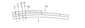
図14はかようなギャップGo近傍で電磁鋼板91が積層される態様を拡大して部分的に示す平面図である。
FIG. 14 is an enlarged plan view partially showing an aspect in which the
そしてもし、巻きコア240の径roと径ro−tの間の領域に、回転磁心24として切り出された後に磁束Φoが流れることになれば、最外層を流れていた磁束Φoは大きな磁気抵抗を有する経路を流れることになる。即ち、最外層を流れていた磁束Φoは、ギャップGoを経由するか、あるいは電磁鋼板91同士の境界を超えて隣接する電磁鋼板91へと流れ、当該電磁鋼板91が最外層へと移るに従って再び最外層に流れることになる。
If the magnetic flux Φo flows in the region between the diameter ro and the diameter rot of the winding
回転磁心24において、このように磁気抵抗が大きい経路を磁束が通ることは、当該磁束がロータとステータとの間をも通って回転電機の動作に直接に影響することに鑑みれば、当然に望ましくない。また、積層方向に磁束が流れると渦電流が電磁鋼板91の面内を流れ、渦電流損が増大する。
In the rotating
以上のように、円環状の巻きコア240の径方向端部のギャップGi,Goにおいて磁束Φi,Φoに対する磁気抵抗が大きくなる傾向がある。これは上述の電磁鋼板91の不連続性の他、巻きコア240から電磁鋼板91が剥がれないように止める溶接による歪みにも起因する。
As described above, the magnetic resistance to the magnetic fluxes Φi and Φo tends to increase in the gaps Gi and Go at the radial ends of the annular winding
そこで、本実施の形態では回転磁心24の外径から内側へ向かって幅2t〜3t程度の領域、内径から外側へ向かって幅2t〜3t程度の領域に磁束が通ることを回避する配置を規定する。
Therefore, in the present embodiment, an arrangement for avoiding magnetic flux from passing through a region having a width of about 2t to 3t from the outer diameter to the inside of the rotating
図15は回転磁心24において永久磁石22が配置される領域221を示す平面図である。第1の実施の形態で述べたように、溶接位置242は永久磁石22よりも周方向において外側にあることが望ましいため、領域221は回転磁心24において溶接位置242に挟まれて位置している。
FIG. 15 is a plan view showing a
また、上述のように、ギャップGi,Go(図13、図14参照)に界磁磁束が流れないように、領域221の外周端と回転磁心24の外周端との距離Δo1、領域221の内周端と回転磁心24の内周端との距離Δi1のいずれもが、幅2t以上であることが望ましい。
Further, as described above, the distance Δo1 between the outer peripheral end of the
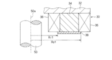
図16は回転磁心24と幅広磁心38との位置関係を示す平面図である。ギャップGi,Goに磁束が流れないように、幅広磁心38の最外周と回転磁心24の外周端との距離Δo2、幅広磁心38の最内周と回転磁心24の内周端との距離Δi2のいずれもが、幅2t以上であることが望ましい。
FIG. 16 is a plan view showing the positional relationship between the rotating
なお、電磁鋼板91を渦巻き状に積層して形成される巻きコア240の径方向における公差は電磁鋼板91の厚さt程度と考えられる。よってこの公差が存在し得ることを考えれば、磁気抵抗が大きい領域に磁束が通ることを回避する観点からは、距離Δi2,Δi1,Δo1,Δo2は幅3t以上であることが望ましい。
The tolerance in the radial direction of the
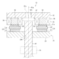
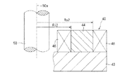
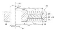
図17は界磁子20の界磁発生部28近傍を拡大して示す断面図であり、シャフト50は側面図として描いている。
FIG. 17 is an enlarged sectional view showing the vicinity of the
永久磁石22の回転磁心24側の面21gは回転軸50aを基準として、内径di3、外径do3を呈している。また回転磁心24の永久磁石22側の面21fは回転軸50aを基準として、内径ri3、外径ro3を呈している。図15を用いて距離Δi1,Δo1についてなされた説明は、ri3+2t<di3<do3<ro3−2tの関係が望ましく、更には回転磁心24の径方向の公差を考慮して、ri3+3t<di3<do3<ro3−3tの関係が望ましいことと同義である。
A surface 21g of the
図18は電機子30のティース34近傍を拡大して示す断面図であり、図19は界磁子20の界磁発生部28近傍を拡大して示す断面図であり、図18及び図19においてシャフト50は側面図として描いている。
18 is an enlarged cross-sectional view showing the vicinity of the
幅広磁心38の界磁子20側の面は回転軸50aを基準として、内径Ri1、外径Ro1を呈している(図18)。回転磁心24の電機子30側の面は磁極面21aとなっており、回転軸50aを基準として、内径ri1、外径ro1を呈している(図19、図8)。
図16を用いて距離Δi2,Δo2についてなされた説明は、ri1+2t<Ri1<Ro1<ro1−2tの関係が望ましく、更には回転磁心24の径方向の公差を考慮して、ri1+3t<Ri1<Ro1<ro1−3tの関係が望ましいことと同義である。
The surface of the wide
The explanation given for the distances Δi2 and Δo2 with reference to FIG. 16 preferably has a relationship of
本実施の形態で説明された好適な位置関係は、回転子を両側から固定子で挟む、いわゆるダブルステータ型のアキシャルギャップ形モータに適用することもできる。図20はアキシャルギャップ型回転電機10の他の構成を例示する斜視図であり、回転軸50aに沿って分解して示している。但し、回転電機の分野の通常の技術知識を有する者であれば、当該回転電機の構成を図20から認識することができる。
The preferred positional relationship described in the present embodiment can also be applied to a so-called double stator type axial gap type motor in which a rotor is sandwiched between stators from both sides. FIG. 20 is a perspective view illustrating another configuration of the axial gap type rotating
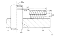
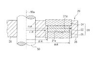
当該構成においては、界磁子20を回転軸50aに沿って界磁子20両側から電機子30及び固定子40で挟む構成を採っており、固定子40は電機子として機能する(例えば上述の特許文献2参照)。図21は固定子40の磁極近傍を拡大して示す断面図であり、図22及び図23は界磁子20の界磁発生部28近傍を拡大して示す断面図である。図21乃至図23においてシャフト50は側面図として描いている。
The configuration employs a configuration in which the
固定子40は電機子30と同様の構成を採っており、具体的にはバックヨーク42と、複数のティース44と、複数のコイル46とを有している。また図20では幅広磁心38と同様にして、幅広磁芯48が設けられている場合を例示しているが、図21では幅広磁芯48を設けない場合を例示している。
The
バックヨーク42はバックヨーク32と同様に構成されており、略中央部に孔部42hが形成された略円盤板状の磁性体が採用される。バックヨーク42はティース44を、界磁子20とは反対側で支持している。固定子40に対して界磁子20と反対側に負荷が設けられない場合には、シャフト50は固定子40を貫通する必要がないので、バックヨーク42に孔部42hを設ける必要もない。
The
ティース44も、ティース34と同様に回転軸50a周りの周方向に沿って間隔をあけて環状に配設されている。各コイル46は、各ティース44に巻回されている。
Similarly to the
界磁子20が固定子40と対向することから、界磁子20はバックヨーク23を有さず、界磁発生部28は永久磁石22の固定子40側に回転磁心24と同様に形成された回転子磁心25を有している。即ち回転子磁心25は、回転軸50aに沿って見て、回転軸50aに対して凹となる、弧状の電磁鋼板の複数を有している。
Since the
各永久磁石22及び各回転子磁心24,25は、非磁性体によって形成されるホルダ26によって上記配設形態で保持され、シャフト50もホルダ26に固定される(図22、図23)。図20ではホルダ26及びシャフト50の図示を省略している。
The
図21を参照して、ティース44の界磁子20側の面は回転軸50aを基準として、内径Ri2、外径Ro2を呈している。図22を参照して、回転磁心25の固定子40側の面は磁極面21cとなっており、回転軸50aを基準として、内径ri2、外径ro2を呈している。よって図18及び図19で行った説明から明白なように、ri2+2t<Ri2<Ro2<ro2−2tの関係が望ましく、更には回転磁心25の径方向の公差を考慮して、ri2+3t<Ri2<Ro2<ro2−3tの関係が望ましい。
Referring to FIG. 21, the surface on the
図23を参照して、永久磁石22の回転磁心25側の面21dは回転軸50aを基準として、内径di4、外径do4を呈している。また回転磁心25の永久磁石22側の面21eは回転軸50aを基準として、内径ri4、外径ro4を呈している。よって図17で行った説明から明白なように、ri4+2t<di4<do4<ro4−2tの関係が望ましく、更には回転磁心25の径方向の公差を考慮して、ri4+3t<di4<do4<ro4−3tの関係が望ましい。
Referring to FIG. 23, the
図24は、アキシャルギャップ型回転電機10の更に他の構成を例示する斜視図であり、固定子40は電機子としては機能せず、バックヨーク42のみで構成されている。かかるアキシャルギャップ型回転電機10では、磁極面21bとバックヨーク42との間の磁気的吸引力によって、回転軸50aに沿った方向での電機子30と界磁子20との磁気的な吸引力を相殺する。かかる技術は例えば上述の特許文献3に紹介されている。
FIG. 24 is a perspective view illustrating still another configuration of the axial gap type rotating
このような構造のアキシャルギャップ型回転電機10においても、永久磁石22と回転磁心24の間で、また回転磁心24と幅広磁心38との間で、上述の寸法関係が成立することが望ましいことは明白である。
Also in the axial gap type rotating
第3の実施の形態.
本実施の形態では、いわゆるq軸インダクタンスを高める工夫について説明する。q軸インダクタンスを高めることによって、いわゆるd軸インダクタンスとq軸インダクタンスとの差を大きくし、リラクタンストルクを得やすくする。
Third embodiment.
In the present embodiment, a device for increasing so-called q-axis inductance will be described. By increasing the q-axis inductance, the difference between the so-called d-axis inductance and the q-axis inductance is increased, and the reluctance torque is easily obtained.
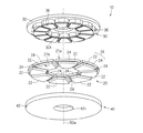
図25は本実施の形態が採用される界磁子20の構成を示す斜視図である。界磁子20は界磁発生部28として上述の永久磁石22及び各回転子磁心24,25を有している他、磁性体29をも有している。界磁発生部28と磁性体29とは回転軸50aの周囲で交互に環状に配設されている。界磁発生部28と磁性体29とは、非磁性体のホルダ(図示省略)によって上記配設形態で保持され、図示されないシャフトも当該ホルダに固定される。
FIG. 25 is a perspective view showing the configuration of the
図25においては永久磁石22と各回転子磁心24,25とは回転軸50aから見てほぼ同じ形状を呈している。但し第1の実施の形態、第2の実施の形態で説明したような、永久磁石22と各回転子磁心24,25の内径、外径、周方向の寸法についての関係が、満足されることが望ましい。
In FIG. 25, the
このように、回転軸50aの周囲で、磁性体たる回転磁心24と周方向に交互に配置される磁性体29を更に備えることにより、q軸インダクタンスが高まる。よってこのような構成を採る界磁子20を採用することにより、リラクタンストルクを利用するモータが実現できる。
Thus, the q-axis inductance is increased by further providing the rotating
磁性体29は、圧粉磁心や、打ち抜かれた電磁鋼板を単に径方向に積層して形成してもよい。特に磁性体29は、積層された複数の鋼板を有することが望ましい。磁性体29を回転磁心24と同じ鋼板を用いて製造することで、材料の無駄が低減するからである。
The
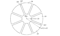
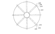
図26は磁性体29を製造する工程を示す平面図であり、巻きコア240をその中心軸に平行に見た図である。
FIG. 26 is a plan view showing a process of manufacturing the
磁性体29は回転磁心24と共に、巻きコア240から切り出して得られる。まず巻きコア240を、電磁鋼板91を巻いて円環状に形成する(図12参照)。その後、巻きコア240を放射状の切断位置243(図中一点鎖線で示す)で切断する。切断位置243の両側で、第1の実施の形態で説明したように、積層された鋼板同士を予め溶接しておくことが望ましい。
The
これにより、狭く隣接した切断位置243に挟まれた巻きコア240が磁性体29として切り出され、それ以外の巻きコア240が回転磁心24として切り出される。
Thereby, the winding
なお、磁性体29の軸方向の厚さは、回転磁心24の軸方向の厚さと永久磁石22の軸方向の厚さの和程度を有することが望ましい。この厚さを得るために、磁性体29は、狭く隣接した切断位置243に挟まれた巻きコア240を更に径方向に延びた切断位置244(図中二点鎖線で示す)で切断し、切断された部位の二つを軸方向に重ねて配置してもよい。
The axial thickness of the
図27は磁性体29の径方向端部の一方の近傍を拡大して示す平面図である。磁性体29は回転磁心24と比較して細くなる。よって、磁性体29の、径方向端部における鋼板の強度不足を防止するためには、図29で示されるような電磁鋼板91の巻き端が磁性体29に存在することは望ましくない。換言すれば、電磁鋼板91の巻き端は回転磁心24に含められることが望ましい。
FIG. 27 is an enlarged plan view showing one vicinity of the radial end of the
変形.
幅広磁心38,48は回転軸50a方向に積層された電磁鋼板、あるいは圧粉鉄心を採用することが望ましい。電磁鋼板を巻いて形成した円環状の巻きコア以外の構造を採ることにより、幅広磁心38,48と回転磁心24,25との間の位置関係を複雑にしないためである。
Deformation.
The wide
10 アキシャルギャップ型回転電機
20 界磁子
22 永久磁石
24,25 回転子磁心
28 界磁発生部
50a 回転軸
30 電機子
91 電磁鋼板
10 Axial gap type rotating
DESCRIPTION OF
Claims (19)
前記回転軸の周囲で周方向に複数個配置され、その各々が前記回転軸に沿った方向である回転軸方向の一方側に呈する第1磁極面と、前記回転軸方向の他方側に呈する第2磁極面とを有する永久磁石(22)と、
前記第1磁極面を前記一方側から覆って設けられた第1の磁性体(24)と
を備え、
前記第1の磁性体は、前記回転軸に沿って見て前記回転軸に対して凹となる弧状の鋼板(91)の複数を有し、
前記鋼板は、その属する前記第1の磁性体が設けられた位置において前記回転軸に垂直に積層された界磁子。 A field element (20) rotating around a rotation axis (50a),
A plurality of circumferentially arranged circumferences of the rotation axis, each of which is provided on one side of the rotation axis direction that is a direction along the rotation axis, and on the other side of the rotation axis direction. A permanent magnet (22) having two magnetic pole faces;
A first magnetic body (24) provided to cover the first magnetic pole surface from the one side;
The first magnetic body has a plurality of arcuate steel plates (91) that are concave with respect to the rotation axis when viewed along the rotation axis,
The steel plate is a field element that is stacked perpendicularly to the rotation axis at a position where the first magnetic body to which the steel plate belongs is provided.
電機子巻線(36)が巻回されて前記回転軸(50a)の周囲に複数個配置されたティース(38)を有し、前記ティースを前記界磁子へと前記一方側から対向させる電機子(30)と
を備える回転電機(10)であって、
前記磁性体(24)の前記ティース側の外径(ro1;ro2)は、前記ティースの前記磁性体側の外径(Ro1;Ro2)に対し、前記鋼板(91)の厚み(t)の2倍以上大きい回転電機。 A field element (20) according to any one of claims 1 to 8;
An electric machine having a plurality of teeth (38) around which the armature winding (36) is wound and arranged around the rotating shaft (50a), and facing the teeth from the one side to the field element A rotating electrical machine (10) comprising a child (30),
The outer diameter (ro1; ro2) on the teeth side of the magnetic body (24) is twice the thickness (t) of the steel plate (91) with respect to the outer diameter (Ro1; Ro2) on the magnetic body side of the teeth. Larger rotating electric machine.
電機子巻線(36)が巻回されて前記回転軸(50a)の周囲に複数個配置されたティース(38)を有し、前記ティースを前記界磁子へと前記一方側から対向させる電機子(30)と
を備える回転電機(10)であって、
前記磁性体(24)の前記ティース側の内径(ri1;ri2)は、前記ティースの前記磁性体側の内径(Ri1;Ri2)に対し、前記鋼板(91)の厚み(t)の2倍以上小さい回転電機。 A field element (20) according to any one of claims 1 to 8;
An electric machine having a plurality of teeth (38) around which the armature winding (36) is wound and arranged around the rotating shaft (50a), and facing the teeth from the one side to the field element A rotating electrical machine (10) comprising a child (30),
The inner diameter (ri1; ri2) on the teeth side of the magnetic body (24) is at least twice the thickness (t) of the steel plate (91) with respect to the inner diameter (Ri1; Ri2) on the magnetic body side of the teeth. Rotating electric machine.
(a)前記鋼板(91)を巻いて形成した円環状の巻きコア(240)を形成する工程と、
(b)前記巻きコアを径方向に沿った切断位置(241)で切断して前記第1磁性体を切り出す工程と
を備える界磁子の製造方法。 A method for producing the field element according to claim 6, comprising:
(A) forming an annular wound core (240) formed by winding the steel plate (91);
(B) A method of manufacturing a field element, comprising: cutting the wound core at a cutting position (241) along a radial direction to cut out the first magnetic body.
を更に備える、請求項14記載の界磁子の製造方法。 (C) After the step (a), before the step (b), further comprising the step of welding the steel plates (91) at the positions (242) on both sides in the circumferential direction of the cutting position (241). The manufacturing method of the field element of Claim 14.
を更に備える、請求項14記載の界磁子の製造方法。 (C) The manufacturing method of the field element of Claim 14 further equipped with the process of adhering the said steel plates (91) with an insulator after the said process (a) and before the said process (b).
(a)前記鋼板(91)を巻いて形成した円環状の巻きコア(240)を形成する工程と、
(b)前記巻きコアを放射状の切断位置(243)で切断し、前記第1磁性体と前記第2磁性体とを切り出す工程と
を備える、界磁子の製造方法。 A method for producing the field element according to claim 8, comprising:
(A) forming an annular wound core (240) formed by winding the steel plate (91);
(B) A method of manufacturing a field element, comprising: cutting the wound core at a radial cutting position (243) to cut out the first magnetic body and the second magnetic body.
Priority Applications (1)
| Application Number | Priority Date | Filing Date | Title |
|---|---|---|---|
| JP2008160261A JP2010004635A (en) | 2008-06-19 | 2008-06-19 | Field magneton, manufacturing method therefor, and rotating electrical machine |
Applications Claiming Priority (1)
| Application Number | Priority Date | Filing Date | Title |
|---|---|---|---|
| JP2008160261A JP2010004635A (en) | 2008-06-19 | 2008-06-19 | Field magneton, manufacturing method therefor, and rotating electrical machine |
Publications (1)
| Publication Number | Publication Date |
|---|---|
| JP2010004635A true JP2010004635A (en) | 2010-01-07 |
Family
ID=41585869
Family Applications (1)
| Application Number | Title | Priority Date | Filing Date |
|---|---|---|---|
| JP2008160261A Pending JP2010004635A (en) | 2008-06-19 | 2008-06-19 | Field magneton, manufacturing method therefor, and rotating electrical machine |
Country Status (1)
| Country | Link |
|---|---|
| JP (1) | JP2010004635A (en) |
Cited By (6)
| Publication number | Priority date | Publication date | Assignee | Title |
|---|---|---|---|---|
| WO2014208110A1 (en) * | 2013-06-28 | 2014-12-31 | 株式会社日立産機システム | Axial type rotating electrical machine |
| WO2015049858A1 (en) | 2013-10-01 | 2015-04-09 | 川崎重工業株式会社 | Robot and robot control method |
| WO2015162961A1 (en) * | 2014-04-23 | 2015-10-29 | 株式会社日立産機システム | Axial gap rotating electric machine |
| CN110417157A (en) * | 2019-08-15 | 2019-11-05 | 上海大学 | A multi-phase axial flux permanent magnet synchronous motor |
| CN117001228A (en) * | 2023-09-26 | 2023-11-07 | 常州昭辉机械有限公司 | Structural member welding equipment with quick positioning function |
| EP4404433A1 (en) * | 2023-01-17 | 2024-07-24 | Magnax | Axial flux machine with high-speed rotor disk |
Citations (6)
| Publication number | Priority date | Publication date | Assignee | Title |
|---|---|---|---|---|
| JPH0670476U (en) * | 1993-03-05 | 1994-09-30 | 東京電気株式会社 | Brushless motor |
| JPH09163642A (en) * | 1995-12-01 | 1997-06-20 | Namiki Precision Jewel Co Ltd | Flat motor and stator manufacturing method thereof |
| JP2005269778A (en) * | 2004-03-18 | 2005-09-29 | Equos Research Co Ltd | Axial gap rotating electric machine |
| JP2006304474A (en) * | 2005-04-20 | 2006-11-02 | Fujitsu General Ltd | Axial air gap type electric motor |
| JP2008022663A (en) * | 2006-07-14 | 2008-01-31 | Daikin Ind Ltd | Rotating electric machine |
| JP2008079362A (en) * | 2006-09-19 | 2008-04-03 | Daikin Ind Ltd | Motor and compressor |
-
2008
- 2008-06-19 JP JP2008160261A patent/JP2010004635A/en active Pending
Patent Citations (6)
| Publication number | Priority date | Publication date | Assignee | Title |
|---|---|---|---|---|
| JPH0670476U (en) * | 1993-03-05 | 1994-09-30 | 東京電気株式会社 | Brushless motor |
| JPH09163642A (en) * | 1995-12-01 | 1997-06-20 | Namiki Precision Jewel Co Ltd | Flat motor and stator manufacturing method thereof |
| JP2005269778A (en) * | 2004-03-18 | 2005-09-29 | Equos Research Co Ltd | Axial gap rotating electric machine |
| JP2006304474A (en) * | 2005-04-20 | 2006-11-02 | Fujitsu General Ltd | Axial air gap type electric motor |
| JP2008022663A (en) * | 2006-07-14 | 2008-01-31 | Daikin Ind Ltd | Rotating electric machine |
| JP2008079362A (en) * | 2006-09-19 | 2008-04-03 | Daikin Ind Ltd | Motor and compressor |
Cited By (11)
| Publication number | Priority date | Publication date | Assignee | Title |
|---|---|---|---|---|
| WO2014208110A1 (en) * | 2013-06-28 | 2014-12-31 | 株式会社日立産機システム | Axial type rotating electrical machine |
| JP2015012675A (en) * | 2013-06-28 | 2015-01-19 | 株式会社日立産機システム | Rotor and axial rotary electric machine employing rotor |
| US9935510B2 (en) | 2013-06-28 | 2018-04-03 | Hitachi Industrial Equipment Systems Co., Ltd. | Axial-type rotary electric machine |
| WO2015049858A1 (en) | 2013-10-01 | 2015-04-09 | 川崎重工業株式会社 | Robot and robot control method |
| WO2015162961A1 (en) * | 2014-04-23 | 2015-10-29 | 株式会社日立産機システム | Axial gap rotating electric machine |
| JP2015208176A (en) * | 2014-04-23 | 2015-11-19 | 株式会社日立産機システム | Axial gap type rotating electrical machine |
| CN110417157A (en) * | 2019-08-15 | 2019-11-05 | 上海大学 | A multi-phase axial flux permanent magnet synchronous motor |
| EP4404433A1 (en) * | 2023-01-17 | 2024-07-24 | Magnax | Axial flux machine with high-speed rotor disk |
| WO2024153584A1 (en) | 2023-01-17 | 2024-07-25 | Magnax | Axial flux machine with high-speed rotor disk |
| CN117001228A (en) * | 2023-09-26 | 2023-11-07 | 常州昭辉机械有限公司 | Structural member welding equipment with quick positioning function |
| CN117001228B (en) * | 2023-09-26 | 2023-12-01 | 常州昭辉机械有限公司 | Structural member welding equipment with quick positioning function |
Similar Documents
| Publication | Publication Date | Title |
|---|---|---|
| CN102111028B (en) | Axial gap rotating electrical machine and rotor used therefor | |
| US10348174B2 (en) | Electric motor | |
| CN101741153A (en) | Armature core, motor and axial gap electrical rotating machine using same and method for making same | |
| WO2002031947A1 (en) | Electric motor | |
| JP5365074B2 (en) | Axial gap type rotating electrical machine | |
| JP2010081789A (en) | Radial gap type rotary electric machine | |
| JP4687687B2 (en) | Axial gap type rotating electric machine and field element | |
| JP2002345189A (en) | Permanent magnet embedded synchronous motor | |
| JP4984347B2 (en) | Electric motor | |
| JP4640373B2 (en) | Rotating electric machine | |
| JP2011223704A (en) | Stator core for rotary electric machine | |
| JP4515236B2 (en) | Embedded magnet type rotor | |
| CN105723596A (en) | Magnetic induction motor and production method for same | |
| JP2010004635A (en) | Field magneton, manufacturing method therefor, and rotating electrical machine | |
| JP6350612B2 (en) | Rotating electric machine | |
| JP5320987B2 (en) | Axial gap type rotating electrical machine | |
| JP5672149B2 (en) | Rotating electric machine rotor and rotating electric machine using the same | |
| US11830668B2 (en) | Method of manufacturing permanent magnet of rotor for axial flux electric machine yielding permanent magnet with low loss and low cost | |
| JP4568639B2 (en) | Stator | |
| JP2011223751A (en) | Rotor and stator core | |
| JP6745212B2 (en) | Rotor and reluctance rotating electric machine | |
| JP2008211892A (en) | Axial gap type rotating electrical machine | |
| JP2007143305A (en) | Core manufacturing method, stator manufacturing method, and motor manufacturing method | |
| JP2004166354A (en) | Motor | |
| JP2011193627A (en) | Rotor core and rotary electric machine |
Legal Events
| Date | Code | Title | Description |
|---|---|---|---|
| A621 | Written request for application examination |
Free format text: JAPANESE INTERMEDIATE CODE: A621 Effective date: 20110520 |
|
| A131 | Notification of reasons for refusal |
Free format text: JAPANESE INTERMEDIATE CODE: A131 Effective date: 20121106 |
|
| A977 | Report on retrieval |
Free format text: JAPANESE INTERMEDIATE CODE: A971007 Effective date: 20121107 |
|
| A02 | Decision of refusal |
Free format text: JAPANESE INTERMEDIATE CODE: A02 Effective date: 20130319 |