JP4515236B2 - Embedded magnet type rotor - Google Patents
Embedded magnet type rotor Download PDFInfo
- Publication number
- JP4515236B2 JP4515236B2 JP2004342351A JP2004342351A JP4515236B2 JP 4515236 B2 JP4515236 B2 JP 4515236B2 JP 2004342351 A JP2004342351 A JP 2004342351A JP 2004342351 A JP2004342351 A JP 2004342351A JP 4515236 B2 JP4515236 B2 JP 4515236B2
- Authority
- JP
- Japan
- Prior art keywords
- rotor
- partition plate
- magnet type
- magnet
- separator
- Prior art date
- Legal status (The legal status is an assumption and is not a legal conclusion. Google has not performed a legal analysis and makes no representation as to the accuracy of the status listed.)
- Expired - Fee Related
Links
Images


Description
この発明は、例えば、インナーロータ型のモータにおける埋め込み磁石型のロータに関するものである。 The present invention relates to an embedded magnet type rotor in an inner rotor type motor, for example.
従来から、ロータ内部の孔に複数の永久磁石を配置した埋め込み磁石型のロータが知られている。この埋め込み磁石型のロータの中には、軸方向に沿って積層鋼板を貫通するように永久磁石が埋め込まれているものがあるが、軸長が長い場合には永久磁石内に過大な渦電流が流れて損失が発生し、永久磁石が発熱してしまう。最悪の場合は永久磁石が不可逆減磁してロータとしての機能を発揮できなくなる。このため、前記永久磁石を分割配置するとともに各永久磁石の間に絶縁材を圧入又は接着して設ける場合がある。(例えば、特許文献1参照)。
しかしながら、上記ロータでは永久磁石を分割して配置していることによって隣り合う永久磁石同士で反発力が生じるため、ロータ回転の振動や発熱により経時的に絶縁材が劣化した場合には、前記反発力により接着一体化した分割磁石がバラバラになり、配置ずれが発生してロータ外周面の発生磁界が不均一となり、この結果、モータトルクが低下するという問題がある。 However, in the above rotor, since the permanent magnets are divided and arranged, a repulsive force is generated between the adjacent permanent magnets. Therefore, when the insulating material deteriorates over time due to the vibration or heat generation of the rotor, the repulsion may occur. There is a problem in that the divided magnets that are bonded and integrated by force become disjointed, causing a displacement, and the magnetic field generated on the outer peripheral surface of the rotor becomes non-uniform, resulting in a reduction in motor torque.
そこで、この発明は、永久磁石の不可逆減磁を回避しつつ永久磁石の配置ずれを抑制してロータ外周面の発生磁界を均一化することで、モータトルクを向上させることができる埋め込み磁石型のロータを提供するものである。 Therefore, the present invention is an embedded magnet type that can improve motor torque by preventing the permanent magnet from being displaced and suppressing the displacement of the permanent magnets to make the magnetic field generated on the outer peripheral surface of the rotor uniform. A rotor is provided.
上記の課題を解決するために、請求項1に記載した発明は、ロータ(例えば、実施の形態におけるロータ本体5)に設けた孔部(例えば、実施の形態におけるスロット孔8)に磁石(例えば、実施の形態における永久磁石9)を配置する埋め込み磁石型のロータにおいて、前記ロータは、前記孔部を有する軸方向に分割された複数のロータ部材(例えば、実施の形態におけるロータ部材6)と、前記各ロータ部材の間に配置される仕切り板(例えば、実施の形態におけるセパレータ7)とを備え、前記複数のロータ部材と仕切り板とを軸方向に積層して一体的に形成され、前記仕切り板は、磁石が当接する位置に、前記仕切り板を貫通する開口部(例えば、実施の形態における孔12)を有していることを特徴とする。
このように構成することで、磁石のサイズを小型化することができるとともに、例えば、ロータの振動等により磁石の配置がずれないようにすることができ、さらに、ロータ部材に磁石を組付けてユニット化してから組み合わせることができる。
また、仕切り板と磁石との接触面積を減少させることができる。
In order to solve the above problem, the invention described in claim 1 is directed to a magnet (for example, a
With this configuration, the size of the magnet can be reduced, and for example, the arrangement of the magnet can be prevented from shifting due to the vibration of the rotor, and further, the magnet can be assembled to the rotor member. Can be combined after unitization.
Further, the contact area between the partition plate and the magnet can be reduced.
請求項2に記載した発明は、前記仕切り板が鋼板材であって絶縁層(例えば、実施の形態における絶縁コーティング10)でコーティングされていることを特徴とする。
このように構成することで、磁石間の渦電流の導通を遮断して磁石の発熱を抑制し、減磁が生じないようにすることができる。
The invention described in claim 2 is characterized in that the partition plate is a steel plate material and is coated with an insulating layer (for example, the
By comprising in this way, conduction | electrical_connection of the eddy current between magnets can be interrupted | blocked, the heat_generation | fever of a magnet can be suppressed, and demagnetization can be prevented from occurring.
請求項3に記載した発明は、前記ロータ部材と前記仕切り板が同一素材の電磁鋼板で作られていることを特徴とする。
このように構成することで、通常前記ロータ部材を製作する工程中に前記仕切り板を製作する工程を含めて、工程の一つの流れの中で積層鋼板を製作することができる。
The invention described in claim 3 is characterized in that the rotor member and the partition plate are made of electromagnetic steel plates made of the same material.
By comprising in this way, a laminated steel plate can be manufactured in one flow of a process including the process of manufacturing the said partition plate in the process of manufacturing the said rotor member normally.
請求項4に記載した発明は、前記ロータ部材うち軸方向外側に配置された2つのロータ部材の内側面に各々絶縁コーティングされた仕切り板を設けると共に、前記ロータ部材のうち中央のロータ部材の両側面に絶縁コーティングされた仕切り板を設け、これら仕切り板の対向する面に絶縁コーティング層を設けることを特徴とする。 According to a fourth aspect of the present invention, a partition plate is provided on each of the inner surfaces of the two rotor members arranged on the axially outer side of the rotor members, and both sides of the central rotor member of the rotor members are provided. A partition plate coated with an insulating coating is provided on the surface, and an insulating coating layer is provided on the opposing surface of the partition plate .
請求項1に記載した発明によれば、磁石のサイズを小型化することができるとともに、例えば、ロータの振動等により磁石の配置がずれないようにすることができ、さらに、ロータ部材に磁石を組付けてユニット化してから組み合わせることができるため、発熱を抑制するとともにトルクリップルや振動の発生を低減して信頼性を向上することができ、さらに、生産性を向上することができる効果がある。
また、仕切り板と磁石との接触面積を減少させることができるため、磁石の磁束の漏洩を低減することができる効果がある。
According to the first aspect of the present invention, the size of the magnet can be reduced, and the arrangement of the magnet can be prevented from shifting due to, for example, vibration of the rotor. Since it can be assembled after being assembled into a unit, heat generation can be suppressed, torque ripple and vibration can be reduced, reliability can be improved, and productivity can be improved. .
Moreover, since the contact area of a partition plate and a magnet can be reduced, there exists an effect which can reduce the leakage of the magnetic flux of a magnet.
請求項2に記載した発明によれば、請求項1の効果に加え、磁石間の渦電流の導通を遮断して磁石の発熱を抑制し、減磁が生じないようにすることができるため、エネルギー効率を向上させることができる効果がある。 According to the second aspect of the present invention, in addition to the effect of the first aspect, the conduction of eddy currents between the magnets can be interrupted to suppress the heat generation of the magnets so that demagnetization does not occur. There is an effect that energy efficiency can be improved.
請求項3に記載した発明によれば、請求項1又は請求項2の効果に加え、通常前記ロータ部材を製作する工程中に前記仕切り板を製作する工程を含めて、工程の一つの流れの中で積層鋼板を製作することができるため、磁石のエネルギーが高く渦電流損の小さいロータを単一の工程で製作することができる効果がある。 According to the third aspect of the present invention, in addition to the effect of the first or second aspect, the process of manufacturing the partition plate is usually included in the process of manufacturing the rotor member. Since a laminated steel sheet can be manufactured, there is an effect that a rotor having high magnet energy and low eddy current loss can be manufactured in a single process.
請求項4に記載した発明によれば、請求項1、請求項2又は請求項3の効果に加え、仕切り板と磁石との接触面積を減少させることができるため、磁石の磁束の漏洩を低減することができる効果がある。 According to the invention described in claim 4, in addition to the effect of claim 1, claim 2, or claim 3, the contact area between the partition plate and the magnet can be reduced, so that leakage of magnetic flux of the magnet is reduced. There is an effect that can be done.
次に、この発明の第一の実施の形態を図面に基づいて説明する。この第一の実施の形態では本発明の埋め込み磁石型のロータをいわゆるインナーロータ型のDCブラシレスモータに適用している(以下、各実施の形態も同様)。
図1はモータの要部を示したものであり、同図において1はステータを示している。このステータ1は複数のティース2が周方向に配列された円環状のものであり、各ティース2はこの外周近傍に設けられた結合部3によって隣接するティース2と結合され、さらに、前記ティース2にはそれぞれ巻線4が巻装され固定子が構成されている。前記ステータ1の径方向内側には前記ティース2に対向する位置に円環状のロータ本体(ロータ)5が周方向に回転可能に設けられている。
Next, a first embodiment of the present invention will be described with reference to the drawings. In the first embodiment, the embedded magnet type rotor of the present invention is applied to a so-called inner rotor type DC brushless motor (the same applies to the following embodiments).
FIG. 1 shows a main part of the motor. In FIG. 1, reference numeral 1 denotes a stator. The stator 1 has an annular shape in which a plurality of teeth 2 are arranged in the circumferential direction, and each tooth 2 is coupled to an adjacent tooth 2 by a coupling portion 3 provided in the vicinity of the outer circumference. Each has a winding 4 wound thereon to form a stator. An annular rotor body (rotor) 5 is rotatably provided in the circumferential direction at a position facing the teeth 2 on the radially inner side of the stator 1.
図2、図3に示すように、前記ロータ本体5は、軸方向に分割された3つのロータ部材6とセパレータ(仕切り板)7とで構成されている。前記ロータ部材6は円環状の電磁鋼板を積層して形成したものであり、前記ロータ部材6の外周面近傍には前記ロータ部材6の側面に開口部を有した磁石設置用のスロット孔(孔部)8が軸方向に沿って形成されている。一方、前記セパレータ7は、前記各ロータ部材6の間を離間するために絶縁層(図示せず)がコーティングされたものであり、前記ロータ部材6と同様の円環状で、且つ、薄板状に形成された電磁鋼板を用いている。前記各ロータ部材6の間に前記セパレータ7を介装して前記ロータ部材6とセパレータ7とを軸方向に積層し一体的に結合することで前記ロータ本体5が構成されている。ここで、前記セパレータ7の内周縁と外周縁とは前記ロータ部材6の内周面と外周面とにそれぞれ面一に配置されている。
As shown in FIGS. 2 and 3, the
ところで、前記ロータ部材6のスロット孔8には平板状の永久磁石(磁石)9が装着されている。ここで、この永久磁石9のスロット孔8への固定は、永久磁石9とスロット孔8とのクリアランスを樹脂で埋める樹脂充填固定や、樹脂によってモールドした永久磁石9を樹脂を削りながら挿入するいわゆる軽圧入、又は、隙間嵌め固定、あるいは永久磁石9の隙間嵌め固定等の方法で固定することができる。
Incidentally, a flat permanent magnet (magnet) 9 is mounted in the
前記永久磁石9は、希土類やフェライト等の磁石を用いたものであり、ロータ本体5の外周面に前記永久磁石9からの磁束が向かうように配置されている。そして、この永久磁石9は、軸方向の長さが前記ロータ部材6の軸方向の長さと同一に設定され、前記ロータ部材6の側面と、前記永久磁石9の端面とが面一になるように固定されている。また、前記永久磁石9の極性はロータ本体5の径方向ではN極、S極が交互になるように配置され、一方、ロータ本体5の軸方向では、3つの永久磁石9が同一極となるように配置されている。
The
したがって、上記第一の実施の形態によれば、各ロータ部材6を絶縁層がコーティングされた電磁鋼板のセパレータ7により遮蔽することでロータ本体5の振動等により経時的に永久磁石9の配置がずれないようにすることができるため、モータのトルクリップルや振動の発生を低減して信頼性を向上することができる。
Therefore, according to the first embodiment, each
また、前記セパレータ7が絶縁層によってコーティングされているため、永久磁石9間に流れる渦電流を遮断することができ、この結果、前記永久磁石9の発熱を抑制することができる。 さらに、前記ロータ部材6とセパレータ7とが電磁鋼板で形成されており、ロータ部材6を製作する工程中に前記セパレータ7を製作する工程を容易に含めることができるため、製作工程の一つの流れの中でセパレータ7を含む積層鋼板を製作することができる
Further, since the
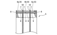
次に、図4〜図5に基づいて第二の実施の形態を説明する。尚、この第二の実施の形態では、前述の第一の実施の形態に対して、セパレータ7と絶縁層とを追加して設けたものであるため、同一部分に動一符号を付して説明する。
図4、図5は、前述した第一の実施の形態の図2と同様に、スロット孔8を備え、このスロット孔8に永久磁石9が装着された円環状の3つのロータ部材6を有したロータ本体5を示したものである。
Next, a second embodiment will be described based on FIGS. In the second embodiment, since the
4 and 5 are similar to FIG. 2 of the first embodiment described above, and have three
これらのロータ部材6のうち、軸方向外側に配置された2つのロータ部材6aの内側面には各々絶縁層でコーティングされた電磁鋼板で形成されたセパレータ7が取り付けられ、さらに、軸方向外側の各ロータ部材6aに挟まれた中央のロータ部材6bには、この両側面に各々セパレータ7が取り付けられている。そして、これらのセパレータ7の対向する面には各々絶縁コーティング(絶縁層)10が形成されており、これらの絶縁コーティング10が前記永久磁石9と接触しないようになっている。すなわち、前記ロータ本体5は、前記3つのロータ部材6(6a,6b)と4枚のセパレータ7とが軸方向に積層されて一体的に形成され、各ロータ部材6a,6bの間には各々2枚のセパレータ7,7と各セパレータ7の絶縁コーティング10が介在しているのである。尚、絶縁コーティング10は何れか一方のセパレータ7の面にのみ施しても良い。
Among these
したがって、上記第二の実施の形態によれば、各セパレータ7の間が絶縁コーティング10によって絶縁処理して各ロータ部材6に埋め込まれた永久磁石9間の絶縁抵抗を増加することができるため、軸方向に沿って配置された各永久磁石9間に流れる渦電流の導通を遮断するとともに、前記永久磁石9の発熱を抑制し、前記永久磁石9が減磁しないようにすることができ、この結果、エネルギー効率の向上を図ることができる。ここで、前記絶縁コーティング10は永久磁石9に接触していないので、絶縁コーティング10が劣化して剥がれたりすることはない。
Therefore, according to the second embodiment, the insulation resistance between the
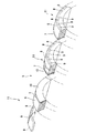
次に、図6に基づいて第三の実施の形態を説明する。尚、この第三の実施の形態では、前述の第一、第二の実施の形態のロータ部材6とセパレータ7と永久磁石9とをユニット化したものであるため、同一部分に同一符号を付して説明する。
図6は、ロータ本体5を分解して示したものである。同図に示すように、円環状のロータ部材6のスロット孔8には永久磁石9が装着され、さらに、このロータ部材6の側面にはセパレータ7が取り付けられている。そして、このロータ部材6に永久磁石9とセパレータ7とが組付けられてロータユニット11が構成されている。すなわち、前記ロータ本体5は3つの前記ロータユニット11を軸方向に一体的に積層して固定することで構成されている。尚、図示都合上、図6では、各ロータ部材6の間に介在するセパレータ7が1枚の場合(図6の紙面右側に示す)と2枚の場合(図6の紙面左側に示す)とを同一図面上に示している。
Next, a third embodiment will be described based on FIG. In the third embodiment, the
FIG. 6 is an exploded view of the
したがって、上記第三の実施の形態によれば、ロータ本体5を組付ける際に、積層構造のロータ部材6のスロット孔8に永久磁石9を装着し、さらに、前記ロータ部材6の片側面又は両側面に前記セパレータ7を固定して前記ロータユニット11を構成してから、このロータユニット11を積層して固定するだけでロータ本体5を構成することができるため、とりわけ、ロータ本体5の生産性を向上することができる点で有利となる。
Therefore, according to the third embodiment, when the rotor
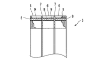
次に、図7に基づいて第四の実施の形態を説明する。この第四の実施の形態は、前述の各実施の形態におけるセパレータ7に孔12を設けたものであるため、同一部分に同一符号を付して説明する。
図7に示すように、前述した各実施の形態と同様に、ロータ本体5はロータ部材6とセパレータ7とが一体に組付けられて構成されている。前記ロータ部材6のスロット孔8(図1参照)には永久磁石9が軸方向に沿って配置されており、この永久磁石9の端面が円環状に形成されたセパレータ7に当接して配置されている。前記セパレータ7には、前記永久磁石9の端面の幅方向略中央に対応した位置に前記セパレータ7を貫通する孔(開口部)12が形成されている。尚、前記セパレータ7には片側面にのみ永久磁石9が当接しているが、両側面に当接するようにしても良い。
Next, a fourth embodiment will be described based on FIG. In the fourth embodiment, since the
As shown in FIG. 7, the
したがって、第四の実施の形態によれば、とりわけ、孔12によりセパレータ7と永久磁石9との接触面積を減少させることができるため、前記永久磁石9の磁束が漏洩するのを低減することができるという点で有利となる。また、前記セパレータ7に孔12を形成する分だけ軽量化を図ることができる。
Therefore, according to the fourth embodiment, in particular, the contact area between the
尚、この発明は上述した実施の形態に限られるものではなく、DCブラシレスモータ以外の種々のモータに用いることができる。また、ロータ本体を一体の円環状としたが、ロータ本体を周方向に分割可能にして、円環状のロータを構成してもよく、さらに、軸方向への分割数は3つに限られるものではなく複数であれば適宜選択してもよい。 In addition, this invention is not restricted to embodiment mentioned above, It can use for various motors other than DC brushless motor. Moreover, although the rotor body is an integral annular shape, the rotor body may be divided in the circumferential direction to constitute an annular rotor, and the number of divisions in the axial direction is limited to three. Instead, a plurality may be selected as appropriate.
また、上記実施の形態では絶縁層がコーティングされた電磁鋼板のセパレータについて説明したが、絶縁層をコーティングする以外に電磁鋼板自体を非導電体に置き換えてもよく、この場合、とりわけ永久磁石の両極間に短絡する磁束を抑制してロータ外周面の発生磁束を確保することができる点で有利となる。 In the above embodiment, the separator of the electromagnetic steel sheet coated with the insulating layer has been described. However, in addition to coating the insulating layer, the electromagnetic steel sheet itself may be replaced with a non-conductive material. It is advantageous in that the magnetic flux generated on the outer peripheral surface of the rotor can be secured by suppressing the magnetic flux short-circuited therebetween.
5 ロータ本体(ロータ)
8 スロット孔(孔部)
9 永久磁石(磁石)
6 ロータ部材
7 セパレータ(仕切り板)
10 絶縁コーティング(絶縁層)
12 孔(開口部)
5 Rotor body (rotor)
8 Slot hole (hole)
9 Permanent magnet (magnet)
6
10 Insulating coating (insulating layer)
12 holes (opening)
Claims (4)
前記ロータは、前記孔部を有する軸方向に分割された複数のロータ部材と、
前記各ロータ部材の間に配置される仕切り板とを備え、
前記複数のロータ部材と仕切り板とを軸方向に積層して一体的に形成され、
前記仕切り板は、磁石が当接する位置に、前記仕切り板を貫通する開口部を有していることを特徴とする埋め込み磁石型のロータ。 In an embedded magnet type rotor in which a magnet is disposed in a hole provided in the rotor,
The rotor includes a plurality of axially divided rotor members having the hole portions;
A partition plate disposed between the rotor members,
The plurality of rotor members and the partition plate are integrally formed by laminating in the axial direction ,
An embedded magnet type rotor , wherein the partition plate has an opening penetrating the partition plate at a position where the magnet contacts .
Priority Applications (1)
| Application Number | Priority Date | Filing Date | Title |
|---|---|---|---|
| JP2004342351A JP4515236B2 (en) | 2004-11-26 | 2004-11-26 | Embedded magnet type rotor |
Applications Claiming Priority (1)
| Application Number | Priority Date | Filing Date | Title |
|---|---|---|---|
| JP2004342351A JP4515236B2 (en) | 2004-11-26 | 2004-11-26 | Embedded magnet type rotor |
Publications (3)
| Publication Number | Publication Date |
|---|---|
| JP2006158037A JP2006158037A (en) | 2006-06-15 |
| JP2006158037A5 JP2006158037A5 (en) | 2006-12-07 |
| JP4515236B2 true JP4515236B2 (en) | 2010-07-28 |
Family
ID=36635652
Family Applications (1)
| Application Number | Title | Priority Date | Filing Date |
|---|---|---|---|
| JP2004342351A Expired - Fee Related JP4515236B2 (en) | 2004-11-26 | 2004-11-26 | Embedded magnet type rotor |
Country Status (1)
| Country | Link |
|---|---|
| JP (1) | JP4515236B2 (en) |
Cited By (1)
| Publication number | Priority date | Publication date | Assignee | Title |
|---|---|---|---|---|
| CN106451854A (en) * | 2016-11-17 | 2017-02-22 | 南京航空航天大学 | Interdigital consequent-pole permanent magnet motor |
Families Citing this family (16)
| Publication number | Priority date | Publication date | Assignee | Title |
|---|---|---|---|---|
| JP4176121B2 (en) | 2006-10-13 | 2008-11-05 | 株式会社三井ハイテック | Rotor laminated iron core and manufacturing method thereof |
| JP5238231B2 (en) * | 2007-11-28 | 2013-07-17 | 株式会社東芝 | Rotating electrical machine rotor |
| JP5103292B2 (en) * | 2008-06-16 | 2012-12-19 | 株式会社三井ハイテック | Rotor laminated iron core and manufacturing method thereof |
| CN102891550B (en) * | 2011-07-20 | 2015-08-19 | 苏州泰铎电气有限公司 | A kind of surface-mounted permanent magnet machine internal rotor iron core and segmented assemblies thereof |
| JP5436525B2 (en) * | 2011-12-05 | 2014-03-05 | 三菱電機株式会社 | Electric motor |
| CN102545435B (en) * | 2012-01-22 | 2014-11-19 | 浙江大学 | Sectional rotor structure for permanent magnet synchronous motor |
| JP5432311B2 (en) * | 2012-03-28 | 2014-03-05 | 株式会社三井ハイテック | Rotor laminated iron core and manufacturing method thereof |
| CN105191069B (en) * | 2013-04-01 | 2017-09-05 | 富士电机株式会社 | Permanent magnet embedded rotating electrical machine |
| EP2966757B1 (en) * | 2014-07-10 | 2016-09-07 | Siemens Aktiengesellschaft | Laminated sheet package assembly and electric machine with such a laminated sheet package assembly |
| JP6324513B2 (en) | 2014-08-21 | 2018-05-16 | 三菱電機株式会社 | Permanent magnet embedded electric motor and compressor |
| WO2017022107A1 (en) | 2015-08-05 | 2017-02-09 | 三菱電機株式会社 | Rotating electric machine rotor, rotating electric machine, fan, and refrigerated air conditioner |
| CN106505760A (en) * | 2016-11-17 | 2017-03-15 | 南京航空航天大学 | A kind of Consequent pole permanent magnet motor of rotor segment |
| CN107809159A (en) * | 2017-10-23 | 2018-03-16 | 中国矿业大学 | A kind of New single-phase cylinder-type transverse-flux switched relutance linear motor |
| CN108448866A (en) * | 2018-04-20 | 2018-08-24 | 中国矿业大学 | A kind of Three phase cylinder-type transverse-flux switched relutance linear motor |
| CN108512392B (en) * | 2018-04-20 | 2021-02-09 | 中国矿业大学 | Cylindrical transverse flux switch reluctance linear motor with modular stator |
| CN112366864B (en) * | 2020-10-29 | 2021-10-01 | 上海电气风电集团股份有限公司 | Motor rotor, motor and mounting method of motor rotor |
Citations (2)
| Publication number | Priority date | Publication date | Assignee | Title |
|---|---|---|---|---|
| JP2002191143A (en) * | 2000-12-20 | 2002-07-05 | Nissan Motor Co Ltd | Permanent magnet synchronous motor and car with the motor |
| JP2004260888A (en) * | 2003-02-25 | 2004-09-16 | Meidensha Corp | Rotor for rotating electric machine |
-
2004
- 2004-11-26 JP JP2004342351A patent/JP4515236B2/en not_active Expired - Fee Related
Patent Citations (2)
| Publication number | Priority date | Publication date | Assignee | Title |
|---|---|---|---|---|
| JP2002191143A (en) * | 2000-12-20 | 2002-07-05 | Nissan Motor Co Ltd | Permanent magnet synchronous motor and car with the motor |
| JP2004260888A (en) * | 2003-02-25 | 2004-09-16 | Meidensha Corp | Rotor for rotating electric machine |
Cited By (2)
| Publication number | Priority date | Publication date | Assignee | Title |
|---|---|---|---|---|
| CN106451854A (en) * | 2016-11-17 | 2017-02-22 | 南京航空航天大学 | Interdigital consequent-pole permanent magnet motor |
| CN106451854B (en) * | 2016-11-17 | 2019-03-29 | 南京航空航天大学 | A kind of interdigital Consequent pole permanent magnet motor |
Also Published As
| Publication number | Publication date |
|---|---|
| JP2006158037A (en) | 2006-06-15 |
Similar Documents
| Publication | Publication Date | Title |
|---|---|---|
| JP4515236B2 (en) | Embedded magnet type rotor | |
| WO2016136384A1 (en) | Armature and rotating electric machine | |
| JP6044382B2 (en) | Multi-gap rotating electric machine | |
| JP2015012679A (en) | Axial gap type rotary electric machine | |
| JP5656719B2 (en) | Permanent magnet type rotating electrical machine and method for manufacturing permanent magnet type rotating electrical machine | |
| WO2016047078A1 (en) | Permanent magnet type rotor and permanent magnet type synchronous rotary electric machine | |
| JP7293371B2 (en) | Rotor of rotary electric machine | |
| WO2017195498A1 (en) | Rotor and rotary electric machine | |
| JP2012115016A (en) | Rotating electric machine | |
| JP6545387B2 (en) | Conscious pole rotor, motor and air conditioner | |
| JP4984347B2 (en) | Electric motor | |
| JP2004328963A (en) | Manufacturing method of rotor for electric motor, and the rotor for electric motor | |
| JP2006254561A (en) | Rotary electric machine | |
| JP2006325295A (en) | Stator | |
| WO2017212575A1 (en) | Permanent magnet motor | |
| JP2010004635A (en) | Field magneton, manufacturing method therefor, and rotating electrical machine | |
| JP2008029130A (en) | Rotating electric machine | |
| JPH11191939A (en) | Motor using rotor embedded with permanent magnet | |
| JP2012125111A (en) | Rotor of outer rotor type rotary machine | |
| CN112448503A (en) | Rotor, motor and driving device | |
| JP2015006110A (en) | Motor device | |
| JP2005080344A (en) | Permanent magnet type rotor | |
| JP2020156199A (en) | Rotary electric machine | |
| JP4760286B2 (en) | motor | |
| JP7325645B2 (en) | Rotating electric machine and manufacturing method of rotating electric machine |
Legal Events
| Date | Code | Title | Description |
|---|---|---|---|
| A521 | Request for written amendment filed |
Free format text: JAPANESE INTERMEDIATE CODE: A523 Effective date: 20061019 |
|
| A621 | Written request for application examination |
Free format text: JAPANESE INTERMEDIATE CODE: A621 Effective date: 20061019 |
|
| A977 | Report on retrieval |
Free format text: JAPANESE INTERMEDIATE CODE: A971007 Effective date: 20091210 |
|
| A131 | Notification of reasons for refusal |
Free format text: JAPANESE INTERMEDIATE CODE: A131 Effective date: 20091218 |
|
| A521 | Request for written amendment filed |
Free format text: JAPANESE INTERMEDIATE CODE: A523 Effective date: 20100212 |
|
| TRDD | Decision of grant or rejection written | ||
| A01 | Written decision to grant a patent or to grant a registration (utility model) |
Free format text: JAPANESE INTERMEDIATE CODE: A01 Effective date: 20100506 |
|
| A01 | Written decision to grant a patent or to grant a registration (utility model) |
Free format text: JAPANESE INTERMEDIATE CODE: A01 |
|
| A61 | First payment of annual fees (during grant procedure) |
Free format text: JAPANESE INTERMEDIATE CODE: A61 Effective date: 20100512 |
|
| R150 | Certificate of patent or registration of utility model |
Ref document number: 4515236 Country of ref document: JP Free format text: JAPANESE INTERMEDIATE CODE: R150 Free format text: JAPANESE INTERMEDIATE CODE: R150 |
|
| FPAY | Renewal fee payment (event date is renewal date of database) |
Free format text: PAYMENT UNTIL: 20130521 Year of fee payment: 3 |
|
| FPAY | Renewal fee payment (event date is renewal date of database) |
Free format text: PAYMENT UNTIL: 20130521 Year of fee payment: 3 |
|
| FPAY | Renewal fee payment (event date is renewal date of database) |
Free format text: PAYMENT UNTIL: 20140521 Year of fee payment: 4 |
|
| LAPS | Cancellation because of no payment of annual fees |