JP5658058B2 - Lithium ion secondary battery - Google Patents
Lithium ion secondary battery Download PDFInfo
- Publication number
- JP5658058B2 JP5658058B2 JP2011041457A JP2011041457A JP5658058B2 JP 5658058 B2 JP5658058 B2 JP 5658058B2 JP 2011041457 A JP2011041457 A JP 2011041457A JP 2011041457 A JP2011041457 A JP 2011041457A JP 5658058 B2 JP5658058 B2 JP 5658058B2
- Authority
- JP
- Japan
- Prior art keywords
- positive electrode
- active material
- electrode active
- ion secondary
- lithium ion
- Prior art date
- Legal status (The legal status is an assumption and is not a legal conclusion. Google has not performed a legal analysis and makes no representation as to the accuracy of the status listed.)
- Expired - Fee Related
Links
Images

Classifications
-
- Y—GENERAL TAGGING OF NEW TECHNOLOGICAL DEVELOPMENTS; GENERAL TAGGING OF CROSS-SECTIONAL TECHNOLOGIES SPANNING OVER SEVERAL SECTIONS OF THE IPC; TECHNICAL SUBJECTS COVERED BY FORMER USPC CROSS-REFERENCE ART COLLECTIONS [XRACs] AND DIGESTS
- Y02—TECHNOLOGIES OR APPLICATIONS FOR MITIGATION OR ADAPTATION AGAINST CLIMATE CHANGE
- Y02E—REDUCTION OF GREENHOUSE GAS [GHG] EMISSIONS, RELATED TO ENERGY GENERATION, TRANSMISSION OR DISTRIBUTION
- Y02E60/00—Enabling technologies; Technologies with a potential or indirect contribution to GHG emissions mitigation
- Y02E60/10—Energy storage using batteries
Description
本発明は、リチウムイオン二次電池に関する。 The present invention relates to a lithium ion secondary battery.
プラグインハイブリッド自動車用電池としてリチウムイオン二次電池を採用するためには、高い安全性を維持しながら、低コスト化、低体積化、軽量化及び高出力化を実現する必要がある。このため、正極材料は、容量が大きく、かつ、安全性が高いことが要求される。 In order to adopt a lithium ion secondary battery as a plug-in hybrid vehicle battery, it is necessary to realize low cost, low volume, light weight and high output while maintaining high safety. For this reason, the positive electrode material is required to have a large capacity and high safety.
特許文献1には、電池内部でのガス発生を抑制することを目的として、リチウム、ニッケル、コバルト及びアルミニウムを含む複合酸化物粒子にモリブデン酸化合物を被着させて加熱処理を行ったもので、炭酸イオンの含有量が0.15重量%以下である正極活物質が開示されている。 In Patent Document 1, for the purpose of suppressing gas generation inside the battery, a heat treatment was performed by adhering a molybdate compound to composite oxide particles containing lithium, nickel, cobalt, and aluminum. A positive electrode active material having a carbonate ion content of 0.15 wt% or less is disclosed.
特許文献2にも、特許文献1と同様の技術が開示されている。 Patent Document 2 also discloses the same technique as Patent Document 1.
特許文献3には、内部抵抗の低減を目的として、B、Bi、Mo、P、Cr、V及びWの中から選ばれた少なくとも1種類以上の元素を添加してなるコバルト酸リチウムもしくはニッケル酸リチウムが正極活物質として開示されている。している。
特許文献1及び2においては、モリブデンの量が複合酸化物に対し、2原子数%(2mol%)以下の量を混合して加熱している。この場合、モリブデンが複合酸化物の表面に偏在するため、充電状態の熱安定性を改善することはできない。 In Patent Documents 1 and 2, the amount of molybdenum is mixed and heated in an amount of 2 atomic% or less (2 mol%) or less with respect to the composite oxide. In this case, since molybdenum is unevenly distributed on the surface of the composite oxide, the thermal stability of the charged state cannot be improved.
特許文献3においては、添加元素の量がコバルト酸リチウムもしくはニッケル酸リチウムに対し、0.1wt.%もしくは10wt.%などであり、充電状態の熱安定性を改善することはできない。
In
このように、特許文献1〜3の技術を用いても、プラグインハイブリッド自動車用電池に要求される容量及び安全性を達成するために十分とは言えない。 Thus, even if it uses the technique of patent documents 1-3, it cannot be said that it is enough in order to achieve the capacity | capacitance and safety which are requested | required of the battery for plug-in hybrid vehicles.
本発明の目的は、放電容量及び安全性を更に向上したリチウムイオン二次電池用正極活物質を提供することにある。 The objective of this invention is providing the positive electrode active material for lithium ion secondary batteries which further improved discharge capacity and safety | security.
本発明においては、組成式Li1.1+xNiaM1 bM2 cO2(式中、M1はMo及びWのうち少なくともいずれかを含み、M2はMnである。−0.07≦x≦0.1、0.90≦a≦0.98、0.02≦b≦0.06、0.00≦c≦0.06である。)で表される正極活物質を用いる。 In the present invention, composition formula Li 1.1 + x Ni a M 1 b M 2 c O 2 (wherein M 1 includes at least one of Mo and W, and M 2 is Mn. −0.07 ≦ x ≦ 0.1, 0.90 ≦ a ≦ 0.98, 0.02 ≦ b ≦ 0.06, and 0.00 ≦ c ≦ 0.06).
本発明によれば、プラグインハイブリッド自動車用電池に要求される放電容量及び安全性を達成するリチウムイオン二次電池用正極活物質を提供することができる。 ADVANTAGE OF THE INVENTION According to this invention, the positive electrode active material for lithium ion secondary batteries which achieves the discharge capacity and safety which are requested | required of the battery for plug-in hybrid vehicles can be provided.
本発明は、容量が大きく、かつ、安全性が高いリチウムイオン二次電池用正極活物質及びこれを用いたリチウムイオン二次電池に関する。 The present invention relates to a positive electrode active material for a lithium ion secondary battery having a large capacity and high safety, and a lithium ion secondary battery using the same.
プラグインハイブリッド自動車用電池としてリチウムイオン二次電池を採用するためには、容量が大きく、かつ、安全性が高いことが要求される。リチウムイオン二次電池において、これらの特性は正極活物質の性質と密接な関係がある。組成式LiMO2(Mは遷移金属である。)で表される層状系の正極活物質において高容量を得るためには、遷移金属中のNi含有量を増やす必要がある。 In order to employ a lithium ion secondary battery as a plug-in hybrid vehicle battery, it is required to have a large capacity and high safety. In the lithium ion secondary battery, these characteristics are closely related to the properties of the positive electrode active material. In order to obtain a high capacity in the layered positive electrode active material represented by the composition formula LiMO 2 (M is a transition metal), it is necessary to increase the Ni content in the transition metal.
しかし、Ni含有量の多い(高Ni含有量の)正極活物質は、充電状態における構造安定性が低く、充電状態における熱安定性が低いという欠点を有する。すなわち、内部短絡などにより電池の温度が上昇した際、比較的低温度で正極から酸素が放出され、この酸素が電解液と反応して急激な発熱を伴う反応を起こす。 However, the positive electrode active material having a high Ni content (high Ni content) has a drawback that the structural stability in the charged state is low and the thermal stability in the charged state is low. That is, when the temperature of the battery rises due to an internal short circuit or the like, oxygen is released from the positive electrode at a relatively low temperature, and this oxygen reacts with the electrolytic solution to cause a reaction with rapid heat generation.
本発明者は、適切な組成の正極活物質を用いることにより、容量を大きくするとともに、充電状態で昇温した場合の最大発熱量を抑制することができ、充電状態における熱安定性を改善できることを見出した。具体的には、高Ni含有量の正極活物質に所定の割合のMo、W又はMnを添加したものである。 By using a positive electrode active material having an appropriate composition, the present inventor can increase the capacity, suppress the maximum heat generation when the temperature is raised in the charged state, and improve the thermal stability in the charged state. I found. Specifically, a predetermined ratio of Mo, W, or Mn is added to a positive electrode active material having a high Ni content.
以下、本発明の一実施形態に係る正極活物質並びにこれを用いた正極材料、正極合剤、正極及びリチウムイオン二次電池について説明する。 Hereinafter, a positive electrode active material according to an embodiment of the present invention, and a positive electrode material, a positive electrode mixture, a positive electrode, and a lithium ion secondary battery using the same will be described.
前記正極活物質は、組成式Li1.1+xNiaM1 bM2 cO2(式中、M1はMo及びWのうち少なくともいずれかを含み、M2はMnである。−0.07≦x≦0.1、0.90≦a≦0.98、0.02≦b≦0.06、0.00≦c≦0.06である。)で表される。 The positive electrode active material has a composition formula of Li 1.1 + x Ni a M 1 b M 2 c O 2 (wherein M 1 includes at least one of Mo and W, and M 2 is Mn. −0. 07 ≦ x ≦ 0.1, 0.90 ≦ a ≦ 0.98, 0.02 ≦ b ≦ 0.06, and 0.00 ≦ c ≦ 0.06).
前記正極活物質は、0.94≦a≦0.98であることが好ましい。 The positive electrode active material preferably satisfies 0.94 ≦ a ≦ 0.98.
前記正極活物質に含まれる遷移金属のうちM1の含有量は、3〜5mol%が好ましい。すなわち、0.03≦b≦0.05であることが好ましい。 The content of M 1 of the transition metal contained in the positive electrode active material is preferably 3~5mol%. That is, it is preferable that 0.03 ≦ b ≦ 0.05.
前記正極活物質は、−0.04≦x≦0.05であることが好ましい。 The positive electrode active material preferably satisfies −0.04 ≦ x ≦ 0.05.
前記正極活物質は、正極材料、正極合剤、正極及びリチウムイオン二次電池に用いることができる。ここで、正極材料は、正極活物質と添加物とを混合したものである。正極合剤は、正極活物質及びバインダを含むものである。正極合剤は、導電助剤を含むことが好ましい。正極は、正極集電板に正極合剤を塗工したものである。 The positive electrode active material can be used for a positive electrode material, a positive electrode mixture, a positive electrode, and a lithium ion secondary battery. Here, the positive electrode material is a mixture of a positive electrode active material and an additive. The positive electrode mixture includes a positive electrode active material and a binder. The positive electrode mixture preferably contains a conductive additive. The positive electrode is obtained by coating a positive electrode current collector plate with a positive electrode mixture.
前記リチウムイオン二次電池は、リチウムを吸蔵放出可能な正極及び負極と、正極と負極との間に挟まれたセパレータと、非水電解質とを含み、正極は、前記正極活物質を含む正極合剤を含む。 The lithium ion secondary battery includes a positive electrode and a negative electrode capable of occluding and releasing lithium, a separator sandwiched between the positive electrode and the negative electrode, and a nonaqueous electrolyte. The positive electrode includes a positive electrode composite containing the positive electrode active material. Contains agents.
前記正極活物質は、Mo、W又はMnを含まない高Ni含有の正極活物質と比較して、電解液と混合して昇温させた際の最大発熱量を大幅に低下させることができ、リチウムイオン二次電池に適用した場合の高温状態における安全性を向上することができる。 The positive electrode active material can significantly reduce the maximum calorific value when mixed with an electrolyte and heated, compared to a high Ni-containing positive electrode active material not containing Mo, W or Mn, Safety in a high temperature state when applied to a lithium ion secondary battery can be improved.
上記の組成式において、x<−0.07の場合、Li層中に存在するLiの量が少ないため、層状の結晶構造を維持できなくなる。一方、0.1<xの場合、複合酸化物における遷移金属の量が少なくなるため、電池の容量が小さくなる。 In the above composition formula, when x <−0.07, since the amount of Li present in the Li layer is small, the layered crystal structure cannot be maintained. On the other hand, in the case of 0.1 <x, the amount of transition metal in the composite oxide decreases, so that the battery capacity decreases.
上記の組成式において、a<0.9の場合、充放電反応に主に寄与するNiの含有量が少ないため、容量が低下する。一方、a>0.98の場合、他の元素の含有量が少なくなるため、熱安定性が低下する。 In the above composition formula, when a <0.9, the content is reduced because the content of Ni mainly contributing to the charge / discharge reaction is small. On the other hand, in the case of a> 0.98, the content of other elements is reduced, so that the thermal stability is lowered.
上記の組成式において、b<0.02の場合、熱安定性を向上する効果が小さい。また、b>0.06の場合、結晶構造が不安定になる。 In the above composition formula, when b <0.02, the effect of improving the thermal stability is small. When b> 0.06, the crystal structure becomes unstable.
上記の組成式において、c>0.06の場合、充放電反応に主に寄与するNiの含有量が減少し、容量が低下する。 In the above composition formula, when c> 0.06, the content of Ni mainly contributing to the charge / discharge reaction is decreased, and the capacity is decreased.
(正極活物質の作製)
リチウムを含まない原料としては、酸化ニッケル並びに二酸化マンガン、酸化モリブテン及び酸化タングステンを適宜使用し、所定の原子比となるように秤量した後、純水を加えて混合することによりスラリーとした。
(Preparation of positive electrode active material)
As raw materials not containing lithium, nickel oxide, manganese dioxide, molybdenum oxide and tungsten oxide were appropriately used, weighed so as to have a predetermined atomic ratio, and then added with pure water and mixed to form a slurry.
このスラリーに含まれる粒子の平均粒径が0.2μmとなるまでジルコニアのビーズミルで粉砕した。このスラリーにポリビニルアルコール(PVA)溶液を固形分比に換算して1wt.%添加し、さらに1時間混合し、スプレードライヤーにより乾燥して造粒した。 The slurry was pulverized with a zirconia bead mill until the average particle size of the particles contained in the slurry became 0.2 μm. In this slurry, a polyvinyl alcohol (PVA) solution was converted to a solid content ratio of 1 wt. % And mixed for another hour, dried by a spray dryer and granulated.
造粒した粒子状の材料にLi:(NiM1M2)比が1.00〜1.25:1となるように水酸化リチウム及び炭酸リチウムを加えた。 Lithium hydroxide and lithium carbonate were added to the granulated particulate material so that the Li: (NiM 1 M 2 ) ratio was 1.00 to 1.25: 1.
次に、得られた粒子状の材料(粉末)を750〜950℃で10時間焼成することにより、層状構造の結晶を有する材料を得た。その後、この材料を解砕して粒子状の正極活物質を得た。 Next, the obtained particulate material (powder) was fired at 750 to 950 ° C. for 10 hours to obtain a material having a layered structure crystal. Thereafter, this material was crushed to obtain a particulate positive electrode active material.
さらに、この正極活物質のうち粒径30μm以上の粗大粒子を分級によって除去した後、電極の作製に用いた。 Further, coarse particles having a particle size of 30 μm or more were removed from the positive electrode active material by classification, and then used for production of an electrode.
正極活物質の作製方法は、上記の方法に限定されるものではなく、共沈法など、他の方法でもよい。 The method for producing the positive electrode active material is not limited to the above method, and other methods such as a coprecipitation method may be used.
表1は、上記の方法で作製した正極活物質の組成比を示したものである。 Table 1 shows the composition ratio of the positive electrode active material produced by the above method.

(試作電池)
正極活物質1と炭素系導電剤とを質量比で85:10.7になるように秤量し、乳鉢を用いて混合した。正極活物質と導電剤との混合材料とN−メチル−2−ピロリドン(NMP)に溶解した結着剤とを、混合材料と溶質である結着剤とが質量比で95.7:4.3になるように均一に混合してスラリーとした。
(Prototype battery)
The positive electrode active material 1 and the carbon-based conductive agent were weighed to a mass ratio of 85: 10.7 and mixed using a mortar. The mixed material of the positive electrode active material and the conductive agent and the binder dissolved in N-methyl-2-pyrrolidone (NMP) are mixed in a mass ratio of 95.7: 4. 3 was mixed uniformly to make a slurry.
このスラリーを厚さ20μmのアルミ集電体箔上に塗布した後、120℃で乾燥し、プレスにて電極密度が2.7g/cm3になるように圧縮成形した。その後、直径15mmの円板状に打ち抜き、正極を作製した。 The slurry was applied on an aluminum current collector foil having a thickness of 20 μm, dried at 120 ° C., and compression-molded with a press so that the electrode density was 2.7 g / cm 3 . Thereafter, it was punched into a disk shape having a diameter of 15 mm to produce a positive electrode.
作製した正極と、金属リチウムで形成された負極とを用い、エチレンカーボネート(EC)とジメチルカーボネート(DMC)とを体積比で1:2の割合で混合した混合溶媒にLiPF6を1.0モル/リットルとなるように溶解させたものを非水電解液として用いて試作電池を作製した。 Using the produced positive electrode and the negative electrode formed of metallic lithium, 1.0 mol of LiPF 6 was mixed in a mixed solvent in which ethylene carbonate (EC) and dimethyl carbonate (DMC) were mixed at a volume ratio of 1: 2. A prototype battery was produced using the non-aqueous electrolyte dissolved in 1 liter / liter.
次に、前述の試作電池を用いて以下の試験を行った。 Next, the following tests were performed using the prototype battery described above.
(充放電試験)
0.1Cで上限電圧4.3Vから下限電圧2.7Vまでの充放電を3回繰り返して初期化した。さらに、0.1Cで上限電圧4.3Vから下限電圧2.7Vまでの充放電を行い、放電容量を測定した。
(Charge / discharge test)
Charging / discharging from the upper limit voltage of 4.3 V to the lower limit voltage of 2.7 V at 0.1 C was repeated three times for initialization. Furthermore, charging / discharging from the upper limit voltage 4.3V to the lower limit voltage 2.7V was performed at 0.1 C, and the discharge capacity was measured.
(示差走査熱量測定)
4.3Vまで定電流/定電圧で充電した後、電極を試作電池から取り出し、DMCで洗浄した後、直径3.5mmの円板状に打ち抜き、サンプルパンに入れ、電解液を1μl(マイクロリットル)加えて密封し、試料とした。
(Differential scanning calorimetry)
After charging at a constant current / constant voltage to 4.3 V, the electrode is taken out from the prototype battery, washed with DMC, punched into a disk shape with a diameter of 3.5 mm, placed in a sample pan, and 1 μl (microliter) of the electrolyte solution. In addition, it was sealed and used as a sample.
この試料を室温から400℃まで5℃/minで昇温した際の発熱挙動を調べた。 The heat generation behavior when this sample was heated from room temperature to 400 ° C. at 5 ° C./min was examined.
〔実施例2〜20、比較例1〜10〕
正極活物質を表1に示すものを用いたこと以外は、実施例1と同様の方法で試作電池を作製し、充放電試験及び示差走査熱量測定を行った。
[Examples 2 to 20, Comparative Examples 1 to 10]
A prototype battery was prepared in the same manner as in Example 1 except that the positive electrode active material shown in Table 1 was used, and a charge / discharge test and differential scanning calorimetry were performed.
実施例1〜20及び比較例1〜10においては、得られた放電容量を比較例1の放電容量で除した値を容量比とした。また、これらの実施例及び比較例においては、得られた発熱量の最大値(最大発熱量)を比較例1の最大発熱量で除した値を最大発熱量比とした。 In Examples 1-20 and Comparative Examples 1-10, the value obtained by dividing the obtained discharge capacity by the discharge capacity of Comparative Example 1 was taken as the capacity ratio. In these Examples and Comparative Examples, the maximum calorific value ratio was obtained by dividing the obtained maximum calorific value (maximum calorific value) by the maximum calorific value of Comparative Example 1.
表2は、実施例1〜8及び比較例1〜3について容量比及び最大発熱量比をまとめて示したものである。 Table 2 summarizes the capacity ratio and the maximum heat generation ratio for Examples 1 to 8 and Comparative Examples 1 to 3.
表2において、実施例1〜7は、Mnを含まずMoを含む正極活物質であって、Liの組成を103〜120の範囲で変化させたものである。実施例8は、実施例1で用いた正極活物質の組成のうち、MoをWに置き換えたものである。 In Table 2, Examples 1-7 are positive electrode active materials which do not contain Mn but contain Mo, and change the composition of Li in the range of 103-120. In Example 8, Mo in the composition of the positive electrode active material used in Example 1 was replaced with W.
比較例1は、実施例に比べてNiが少なく、Co及びMnを含み、Moが含まれていないものである。比較例2は、実施例2よりもLiが少ないものである。比較例3は、実施例7よりもLiが多いものである。 In Comparative Example 1, Ni is less than in the example, Co and Mn are included, and Mo is not included. Comparative Example 2 has less Li than Example 2. Comparative Example 3 has more Li than Example 7.
表2より、実施例1〜8においては、比較例1と比べて放電容量が大きく、最大発熱量が小さいことがわかる。 From Table 2, it can be seen that in Examples 1 to 8, the discharge capacity is larger and the maximum heat generation amount is smaller than in Comparative Example 1.
比較例1と比べて放電容量が大きい値を示したのは、それぞれの実施例の正極活物質に含まれるLiの含有量が適切な範囲となっているためであると考える。また、比較例1と比べて最大発熱量が小さいのは、充電状態の熱安定性に寄与する元素であるMo又はWが適切な量である4%含まれるためであると考える。これに対して、比較例1においては、Niの量が少なく、Moが含まれていない。 The reason why the discharge capacity is larger than that of Comparative Example 1 is considered to be that the content of Li contained in the positive electrode active material of each Example is within an appropriate range. In addition, the reason why the maximum heat generation amount is smaller than that of Comparative Example 1 is considered to be because Mo or W, which is an element contributing to the thermal stability of the charged state, is contained in an appropriate amount of 4%. On the other hand, in Comparative Example 1, the amount of Ni is small and Mo is not included.
一方、比較例2及び3においては、放電容量の向上及び最大発熱量の低減を両立することはできなかった。比較例2においては、Li含有量が少ないため、容量が低下したと考える。比較例3においては、Li含有量が多すぎて結晶中に取り込まれず、充放電に関与することができないため、容量が低下したと考える。 On the other hand, in Comparative Examples 2 and 3, it was impossible to achieve both improvement of the discharge capacity and reduction of the maximum heat generation amount. In Comparative Example 2, it is considered that the capacity is reduced because the Li content is small. In Comparative Example 3, it is considered that the capacity was lowered because the Li content was too large to be taken into the crystal and could not be involved in charge / discharge.
表3は、実施例9〜16及び比較例4〜5について容量比及び最大発熱量比をまとめて示したものである。 Table 3 summarizes the capacity ratio and the maximum heat generation ratio for Examples 9 to 16 and Comparative Examples 4 to 5.
表3において、実施例9は、実施例1の組成のうち、Niを減らしてMnを加えたものである。実施例10は、実施例2の組成のうち、Niを減らしてMnを加えたものである。実施例11〜15は、実施例10の組成のうち、Liの組成を106〜120の範囲で変化させたものである。実施例16は、実施例9の組成のうち、MoをWに置き換えたものである。 In Table 3, Example 9 is a composition obtained by reducing Ni in the composition of Example 1 and adding Mn. In Example 10, among the compositions of Example 2, Ni was reduced and Mn was added. Examples 11-15 change the composition of Li in the range of 106-120 among the compositions of Example 10. FIG. In Example 16, Mo in the composition of Example 9 is replaced with W.
比較例4は、実施例10よりもLiが少ないものである。比較例5は、実施例15よりもLiが多いものである。 Comparative Example 4 has less Li than Example 10. Comparative Example 5 has more Li than Example 15.
表3より、実施例9〜16においては、比較例1と比べて放電容量が大きく、最大発熱量が小さいことがわかる。 From Table 3, it can be seen that in Examples 9 to 16, the discharge capacity is larger and the maximum heat generation amount is smaller than that of Comparative Example 1.
放電容量が大きい値を示したのは、それぞれの実施例の正極活物質に含まれるLiの含有量が適切な範囲となっているためであると考える。また、最大発熱量が小さいのは、充電状態の熱安定性に寄与する元素であるMo又はWが4%含まれるためであると考える。 The reason why the discharge capacity shows a large value is considered to be that the content of Li contained in the positive electrode active material of each example is within an appropriate range. Further, the reason why the maximum heat generation amount is small is considered to be that 4% of Mo or W, which is an element contributing to the thermal stability of the charged state, is included.
一方、比較例4及び5においては、放電容量の向上及び最大発熱量の低減を両立することができなかった。比較例4においては、Li含有量が少ないため、放電容量が低下したと考える。比較例5においては、Li含有量が多すぎて結晶中に取り込まれず、充放電に関与することができないため、放電容量が低下したと考える。 On the other hand, in Comparative Examples 4 and 5, it was impossible to achieve both improvement of the discharge capacity and reduction of the maximum heat generation amount. In Comparative Example 4, it is considered that the discharge capacity is reduced because the Li content is small. In Comparative Example 5, it is considered that the discharge capacity was reduced because the Li content was too high to be taken into the crystal and could not be involved in charge / discharge.
表4は、実施例17〜18及び比較例6〜7について容量比及び最大発熱量比をまとめて示したものである。 Table 4 summarizes the capacity ratio and the maximum calorific value ratio for Examples 17 to 18 and Comparative Examples 6 to 7.
表4において、実施例17は、実施例1の組成のうち、Niを増やしてMoを減らしたものである。実施例18は、実施例1の組成のうち、Niを減らしてMoを増やしたものである。 In Table 4, Example 17 is the composition of Example 1 in which Ni is increased and Mo is decreased. Example 18 is a composition obtained by reducing Ni and increasing Mo in the composition of Example 1.
比較例6は、実施例17より更にNiを増やしてMoを減らしたものである。比較例7は、実施例18より更にNiを減らしてMoを増やしたものである。 In Comparative Example 6, Ni was further increased and Mo was reduced compared to Example 17. In Comparative Example 7, Ni is further reduced and Mo is increased as compared with Example 18.
表4より、実施例17及び18においては、比較例1と比べて放電容量が大きく、最大発熱量が小さいことがわかる。 From Table 4, it can be seen that in Examples 17 and 18, the discharge capacity is larger and the maximum heat generation amount is smaller than in Comparative Example 1.
放電容量が大きい値を示したのは、それぞれの実施例で選択した正極活物質に含まれる遷移金属のうちNiの含有量が多いためであると考える。また、最大発熱量が小さいのは、充電状態の熱安定性に寄与する元素であるMoが2〜6%含まれるためであると考える。 The reason why the discharge capacity shows a large value is considered to be because the Ni content is large among the transition metals contained in the positive electrode active material selected in each example. Further, the reason why the maximum heat generation amount is small is considered to be that 2 to 6% of Mo which is an element contributing to the thermal stability of the charged state is contained.
一方、比較例6及び7においては、放電容量の向上及び最大発熱量の低減を両立することができなかった。比較例6においては、充電状態の熱安定性に寄与する元素であるMoが1%と少ないため、放電容量は大きいが、充電状態の熱安定性が十分に得られなかった。比較例7においては、Moが8%と多すぎるため、放電容量が減少した。 On the other hand, in Comparative Examples 6 and 7, it was impossible to achieve both improvement of the discharge capacity and reduction of the maximum heat generation amount. In Comparative Example 6, Mo, which is an element that contributes to the thermal stability of the charged state, was as low as 1%, and thus the discharge capacity was large, but the thermal stability of the charged state was not sufficiently obtained. In Comparative Example 7, the discharge capacity was reduced because Mo was too much as 8%.
表5は、実施例19〜20及び比較例8〜10について容量比及び最大発熱量比をまとめて示したものである。 Table 5 summarizes the capacity ratio and the maximum heat generation ratio for Examples 19 to 20 and Comparative Examples 8 to 10.
表5において、実施例19は、実施例9の組成のうち、Niを増やしてMoを減らしたものである。実施例20は、実施例9の組成のうち、Mnを減らしてMoを増やしたものである。 In Table 5, Example 19 is a composition obtained by increasing Ni and decreasing Mo in the composition of Example 9. In Example 20, among the compositions of Example 9, Mn was reduced and Mo was increased.
比較例8は、実施例19より更にNiを増やしてMoを減らしたものである。比較例9は、実施例9よりNiを減らしてMoを増やしたものである。 In Comparative Example 8, Ni was further increased and Mo was reduced compared to Example 19. In Comparative Example 9, Ni was reduced and Mo was increased compared to Example 9.
表5より、実施例19及び20においては、比較例1と比べて放電容量が大きく、最大発熱量が小さいことがわかる。放電容量が大きい値を示したのは、それぞれの実施例で選択した正極活物質に含まれる遷移金属のうちNiの含有量が多いためであると考える。また、最大発熱量が小さいのは、充電状態の熱安定性に寄与する元素であるMoが2〜6%含まれるためであると考える。 From Table 5, it can be seen that in Examples 19 and 20, the discharge capacity is larger and the maximum heat generation amount is smaller than in Comparative Example 1. The reason why the discharge capacity shows a large value is considered to be because the Ni content is large among the transition metals contained in the positive electrode active material selected in each example. Further, the reason why the maximum heat generation amount is small is considered to be that 2 to 6% of Mo which is an element contributing to the thermal stability of the charged state is contained.
一方、比較例8〜10においては、放電容量の向上及び最大発熱量の低減を両立することができなかった。比較例8においては、充電状態の熱安定性に寄与する元素であるMoが1%と少ないため、放電容量は大きいが、充電状態の熱安定性が十分に得られなかった。比較例9においては、Moが8%と多すぎるため、放電容量が減少したと考える。また、比較例10においては、Mnが8%と多すぎたため、放電容量が減少したと考える。 On the other hand, in Comparative Examples 8 to 10, it was impossible to achieve both improvement of the discharge capacity and reduction of the maximum heat generation amount. In Comparative Example 8, Mo, which is an element that contributes to the thermal stability of the charged state, is as low as 1%, and thus the discharge capacity is large, but the thermal stability of the charged state cannot be obtained sufficiently. In Comparative Example 9, it is considered that the discharge capacity is reduced because Mo is too much as 8%. Further, in Comparative Example 10, it is considered that the discharge capacity was decreased because Mn was too much as 8%.
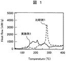
図1は、実施例1及び比較例1の示差走査熱量測定(Differential Scanning Calorimetry:DSC)の結果を示したものである。横軸に温度をとり、縦軸に単位質量当たりの熱流量をとっている。 FIG. 1 shows the results of differential scanning calorimetry (DSC) of Example 1 and Comparative Example 1. The horizontal axis represents temperature, and the vertical axis represents heat flow per unit mass.
本図において、実施例1は、比較例1に比べて熱流量の温度依存性が小さくなっている。これに対して、比較例1は、290℃付近に急峻なピークを有する。 In this figure, the temperature dependence of the heat flow is smaller in Example 1 than in Comparative Example 1. On the other hand, Comparative Example 1 has a steep peak near 290 ° C.
この結果から、実施例1は、充電状態における熱安定性が高いことがわかる。 From this result, it can be seen that Example 1 has high thermal stability in the charged state.
図2は、リチウムイオン二次電池を示す断面図である。 FIG. 2 is a cross-sectional view showing a lithium ion secondary battery.
本図においては、集電体の両面に正極材料を塗布した正極板3(正極とも呼ぶ。)と、集電体の両面に負極材料を塗布した負極板4(負極とも呼ぶ。)とが直接接触しないように、正極板3と負極板4と間にセパレータ5を配置して捲回することにより、電極群を形成している。この電極群は、SUS製の電池缶9に挿入してある。セパレータ5は、微多孔性ポリプロピレンフィルムで形成されている。
In this figure, a positive electrode plate 3 (also referred to as a positive electrode) in which a positive electrode material is applied on both surfaces of a current collector and a negative electrode plate 4 (also referred to as a negative electrode) in which a negative electrode material is applied on both surfaces of the current collector are directly shown. The electrode group is formed by arranging and winding the separator 5 between the
電池缶9には、非水電解液(例えば、エチレンカーボネート(EC)とジメチルカーボネート(DMC)とを体積比で1:2とした混合溶媒に1.0モル/リットルのLiPF6を溶解させたもの)を注入してある。電池缶9は、パッキン10を取り付けた密閉蓋部8を用いて密閉してある。正極板3のリード片6は、密閉蓋部8に電気的に接続してある。また、負極板4のリード片7は、電池缶9の底部に電気的に接続してある。密閉蓋部8と電極群との間、及び電池缶9の底部と電極群との間には、絶縁板11を配置してある。
In the battery can 9, 1.0 mol / liter of LiPF 6 was dissolved in a non-aqueous electrolyte (for example, a mixed solvent of ethylene carbonate (EC) and dimethyl carbonate (DMC) in a volume ratio of 1: 2. Stuff). The battery can 9 is sealed using a sealing lid portion 8 to which a packing 10 is attached. The lead piece 6 of the
以上のように、リチウムイオン二次電池の正極材料として本実施形態で示した材料を用いることにより、プラグインハイブリッド自動車用電池に要求される性能である大容量、高出力及び高い安全性を達成することができる。 As described above, by using the material shown in the present embodiment as the positive electrode material of the lithium ion secondary battery, high capacity, high output and high safety, which are the performance required for the plug-in hybrid vehicle battery, are achieved. can do.
本発明は、特に、リチウムイオン二次電池の正極材料に適用することができる。また、プラグインハイブリッド自動車用のリチウムイオン二次電池にも利用可能である。 The present invention is particularly applicable to a positive electrode material for a lithium ion secondary battery. It can also be used for lithium ion secondary batteries for plug-in hybrid vehicles.
3:正極板、4:負極板、5:セパレータ、6、7:リード片、8:密閉蓋部、9:電池缶、10:パッキン、11:絶縁板。 3: positive electrode plate, 4: negative electrode plate, 5: separator, 6, 7: lead piece, 8: sealing lid, 9: battery can, 10: packing, 11: insulating plate.
Claims (7)
Priority Applications (1)
| Application Number | Priority Date | Filing Date | Title |
|---|---|---|---|
| JP2011041457A JP5658058B2 (en) | 2011-02-28 | 2011-02-28 | Lithium ion secondary battery |
Applications Claiming Priority (1)
| Application Number | Priority Date | Filing Date | Title |
|---|---|---|---|
| JP2011041457A JP5658058B2 (en) | 2011-02-28 | 2011-02-28 | Lithium ion secondary battery |
Publications (3)
| Publication Number | Publication Date |
|---|---|
| JP2012178312A JP2012178312A (en) | 2012-09-13 |
| JP2012178312A5 JP2012178312A5 (en) | 2013-03-21 |
| JP5658058B2 true JP5658058B2 (en) | 2015-01-21 |
Family
ID=46980027
Family Applications (1)
| Application Number | Title | Priority Date | Filing Date |
|---|---|---|---|
| JP2011041457A Expired - Fee Related JP5658058B2 (en) | 2011-02-28 | 2011-02-28 | Lithium ion secondary battery |
Country Status (1)
| Country | Link |
|---|---|
| JP (1) | JP5658058B2 (en) |
Families Citing this family (3)
| Publication number | Priority date | Publication date | Assignee | Title |
|---|---|---|---|---|
| WO2015037111A1 (en) * | 2013-09-13 | 2015-03-19 | 株式会社日立製作所 | Positive-electrode active material for use in lithium-ion secondary batteries and lithium-ion secondary battery using said positive-electrode active material |
| WO2015141179A1 (en) * | 2014-03-17 | 2015-09-24 | 三洋電機株式会社 | Non-aqueous electrolyte secondary battery |
| JP2017120765A (en) * | 2015-12-25 | 2017-07-06 | パナソニック株式会社 | Nonaqueous electrolyte secondary battery |
Family Cites Families (5)
| Publication number | Priority date | Publication date | Assignee | Title |
|---|---|---|---|---|
| JP3229425B2 (en) * | 1993-03-29 | 2001-11-19 | 松下電器産業株式会社 | Positive electrode for lithium secondary battery and method for producing the same |
| JP4161382B2 (en) * | 1997-02-25 | 2008-10-08 | 堺化学工業株式会社 | Process for producing two-layer structured particulate composition |
| KR100578877B1 (en) * | 2004-03-12 | 2006-05-11 | 삼성에스디아이 주식회사 | Rechargeable lithium battery |
| CN100463284C (en) * | 2004-04-07 | 2009-02-18 | 松下电器产业株式会社 | Nonaqueous electrolyte secondary battery |
| JP2009224097A (en) * | 2008-03-14 | 2009-10-01 | Panasonic Corp | Nonaqueous electrolyte secondary battery |
-
2011
- 2011-02-28 JP JP2011041457A patent/JP5658058B2/en not_active Expired - Fee Related
Also Published As
| Publication number | Publication date |
|---|---|
| JP2012178312A (en) | 2012-09-13 |
Similar Documents
| Publication | Publication Date | Title |
|---|---|---|
| JP5389620B2 (en) | Positive electrode material for lithium ion secondary battery and lithium ion secondary battery using the same | |
| KR101321192B1 (en) | Lithium secondary battery | |
| JP4951638B2 (en) | Positive electrode material for lithium ion secondary battery and lithium ion secondary battery using the same | |
| KR100934612B1 (en) | Cathode active material for nonaqueous electrolyte secondary battery, preparation method thereof, method for manufacturing nonaqueous electrolyte secondary battery, and positive electrode | |
| JP5412298B2 (en) | Positive electrode material for lithium ion secondary battery and lithium ion secondary battery using the same | |
| JP5842596B2 (en) | Positive electrode composition for non-aqueous electrolyte secondary battery and method for producing positive electrode slurry for non-aqueous electrolyte secondary battery | |
| KR101966494B1 (en) | Lithium ion secondary battery | |
| JP5615769B2 (en) | Lithium secondary battery | |
| JP5412453B2 (en) | Positive electrode active material, positive electrode, and lithium ion secondary battery | |
| WO2013128971A1 (en) | Positive electrode material | |
| JP5629609B2 (en) | Lithium secondary battery | |
| JP5475611B2 (en) | Lithium ion secondary battery | |
| JP5658058B2 (en) | Lithium ion secondary battery | |
| JP6273707B2 (en) | Positive electrode active material for non-aqueous electrolyte secondary battery and non-aqueous electrolyte secondary battery using the same | |
| JP5828754B2 (en) | Positive electrode material and lithium ion secondary battery | |
| JP5877898B2 (en) | Positive electrode active material for lithium ion secondary battery | |
| WO2023189507A1 (en) | Positive electrode active material for non-aqueous electrolyte secondary battery, and non-aqueous electrolyte secondary battery | |
| JP5732122B2 (en) | Positive electrode active material, positive electrode, and lithium ion secondary battery | |
| WO2015059779A1 (en) | Positive electrode material for lithium ion secondary batteries, and lithium ion secondary battery | |
| JP2016058334A (en) | Positive electrode material for lithium secondary battery | |
| JP2017004912A (en) | Spinel lithium-manganese composite oxide and method for producing the same, and lithium ion secondary battery and electrochemical device | |
| CN112602212A (en) | Nonaqueous electrolyte secondary battery | |
| WO2016038699A1 (en) | Positive electrode active material for lithium secondary batteries | |
| WO2014167657A1 (en) | Positive electrode material for lithium ion secondary cell and lithium ion secondary cell | |
| WO2014162531A1 (en) | Positive electrode material for lithium ion secondary battery |
Legal Events
| Date | Code | Title | Description |
|---|---|---|---|
| A521 | Written amendment |
Free format text: JAPANESE INTERMEDIATE CODE: A523 Effective date: 20130201 |
|
| A621 | Written request for application examination |
Free format text: JAPANESE INTERMEDIATE CODE: A621 Effective date: 20130201 |
|
| A977 | Report on retrieval |
Free format text: JAPANESE INTERMEDIATE CODE: A971007 Effective date: 20131224 |
|
| A131 | Notification of reasons for refusal |
Free format text: JAPANESE INTERMEDIATE CODE: A131 Effective date: 20140107 |
|
| A521 | Written amendment |
Free format text: JAPANESE INTERMEDIATE CODE: A523 Effective date: 20140310 |
|
| A131 | Notification of reasons for refusal |
Free format text: JAPANESE INTERMEDIATE CODE: A131 Effective date: 20140401 |
|
| A521 | Written amendment |
Free format text: JAPANESE INTERMEDIATE CODE: A523 Effective date: 20140414 |
|
| TRDD | Decision of grant or rejection written | ||
| A01 | Written decision to grant a patent or to grant a registration (utility model) |
Free format text: JAPANESE INTERMEDIATE CODE: A01 Effective date: 20141118 |
|
| A61 | First payment of annual fees (during grant procedure) |
Free format text: JAPANESE INTERMEDIATE CODE: A61 Effective date: 20141127 |
|
| R150 | Certificate of patent or registration of utility model |
Ref document number: 5658058 Country of ref document: JP Free format text: JAPANESE INTERMEDIATE CODE: R150 |
|
| LAPS | Cancellation because of no payment of annual fees |