JP5655314B2 - Solar cell module - Google Patents
Solar cell module Download PDFInfo
- Publication number
- JP5655314B2 JP5655314B2 JP2010016426A JP2010016426A JP5655314B2 JP 5655314 B2 JP5655314 B2 JP 5655314B2 JP 2010016426 A JP2010016426 A JP 2010016426A JP 2010016426 A JP2010016426 A JP 2010016426A JP 5655314 B2 JP5655314 B2 JP 5655314B2
- Authority
- JP
- Japan
- Prior art keywords
- solar cell
- film
- layer
- adhesive layer
- white
- Prior art date
- Legal status (The legal status is an assumption and is not a legal conclusion. Google has not performed a legal analysis and makes no representation as to the accuracy of the status listed.)
- Expired - Fee Related
Links
Images


Classifications
-
- Y—GENERAL TAGGING OF NEW TECHNOLOGICAL DEVELOPMENTS; GENERAL TAGGING OF CROSS-SECTIONAL TECHNOLOGIES SPANNING OVER SEVERAL SECTIONS OF THE IPC; TECHNICAL SUBJECTS COVERED BY FORMER USPC CROSS-REFERENCE ART COLLECTIONS [XRACs] AND DIGESTS
- Y02—TECHNOLOGIES OR APPLICATIONS FOR MITIGATION OR ADAPTATION AGAINST CLIMATE CHANGE
- Y02E—REDUCTION OF GREENHOUSE GAS [GHG] EMISSIONS, RELATED TO ENERGY GENERATION, TRANSMISSION OR DISTRIBUTION
- Y02E10/00—Energy generation through renewable energy sources
- Y02E10/50—Photovoltaic [PV] energy
Description
本発明は、人の目には太陽電池素子とほぼ同色を呈しつつ、近赤外線を反射する機能を有する太陽電池裏面保護シートを具備してなる太陽電池モジュールに関する。
詳しくは、本発明の太陽電池モジュールに用いられる太陽電池裏面保護シートは以下のような特徴を有する。即ち、太陽電池裏面保護シートを構成する層のうち、最も太陽電池素子の裏面を封止する封止剤層に近い接着剤層は、ペリレンブラックを含有するものであり、人の目には太陽電池素子とほぼ同色の黒色と映るが、近赤外線を吸収せずに透過する。そして、太陽電池裏面保護シートを構成する他の層が、透過した近赤外線を反射する。
太陽電池裏面保護シートによって反射された近赤外線を太陽電池素子が発電に利用することができるので、エネルギー変換効率を向上できる。
さらに太陽電池裏面保護シート表面が近赤外線を反射するので、太陽電池裏面保護シート自体の蓄熱が抑制され、太陽電池素子が高温になることが抑制でき、その結果エネルギー変換効率の低下を抑制できる。
The present invention relates to a solar cell module including a solar cell back surface protective sheet that has a function of reflecting near infrared rays while exhibiting substantially the same color as a solar cell element to human eyes.
Specifically, the solar cell back surface protective sheet used in the solar cell module of the present invention has the following characteristics. That is, among the layers constituting the solar cell back surface protective sheet, the adhesive layer closest to the sealant layer that seals the back surface of the solar cell element contains perylene black, and is not suitable for human eyes. Although it appears to be black with the same color as the battery element, it does not absorb near-infrared light and transmits it. And the other layer which comprises a solar cell back surface protection sheet reflects the transmitted near infrared rays.
Since the solar cell element can use the near infrared ray reflected by the solar cell back surface protective sheet for power generation, the energy conversion efficiency can be improved.
Furthermore, since the solar cell back surface protection sheet surface reflects near-infrared rays, heat storage of the solar cell back surface protection sheet itself can be suppressed, and the solar cell element can be suppressed from becoming high temperature, and as a result, a decrease in energy conversion efficiency can be suppressed.
近年、環境問題に対する意識の高まりから環境汚染がなくクリーンなエネルギー源として太陽電池が注目され、有用なエネルギー資源としての太陽エネルギー利用の面から鋭意研究され実用化が進んでいる。
太陽電池素子には様々な形態があり、その代表的なものとして、結晶シリコン太陽電池素子、多結晶シリコン太陽電池素子、非晶質シリコン太陽電池素子、銅インジウムセレナイド太陽電池素子、化合物半導体太陽電池素子等が知られている。この中で薄膜結晶太陽電池素子、非晶質シリコン太陽電池素子、化合物半導体太陽電池素子は比較的低コストであり、また大面積化が可能であるため、各方面で活発に研究開発が行われている。またこれらの太陽電池素子の中でも、導体金属基板上にシリコンを積層し、更にその上に透明導電層を形成した非晶質シリコン太陽電池素子に代表される薄膜太陽電池素子は軽量であり、また耐衝撃性やフレキシブル性に富んでいるので、太陽電池における将来の形態として有望視されている。
In recent years, solar cells have been attracting attention as a clean energy source free from environmental pollution due to an increase in awareness of environmental problems, and earnestly researched and put into practical use from the viewpoint of using solar energy as a useful energy resource.
There are various types of solar cell elements, and typical examples thereof include a crystalline silicon solar cell element, a polycrystalline silicon solar cell element, an amorphous silicon solar cell element, a copper indium selenide solar cell element, and a compound semiconductor solar. Battery elements and the like are known. Among these, thin-film crystal solar cell elements, amorphous silicon solar cell elements, and compound semiconductor solar cell elements are relatively low cost and can be increased in area, and therefore are actively researched and developed in various fields. ing. Among these solar cell elements, thin film solar cell elements represented by amorphous silicon solar cell elements in which silicon is laminated on a conductive metal substrate and a transparent conductive layer is further formed thereon are lightweight, Since it is rich in impact resistance and flexibility, it is considered promising as a future form of solar cells.
太陽電池モジュールのうち、単純なものは、太陽電池素子の両面に充填剤、ガラス板を、順に積層した構成形態を呈する。ガラス板は、透明性、耐候性、耐擦傷性に優れることから、太陽の受光面側の封止シートとして、現在も一般的に用いられている。しかし、透明性を必要としない非受光面側においては、コストや安全性、加工性の面から、ガラス板以外の太陽電池用裏面保護シート(以下裏面保護シート)が各社により開発され、ガラス板に置き換わりつつある。 A simple one of the solar cell modules has a configuration in which a filler and a glass plate are sequentially laminated on both sides of the solar cell element. Since a glass plate is excellent in transparency, weather resistance, and scratch resistance, it is still generally used as a sealing sheet on the solar light receiving surface side. However, on the non-light-receiving surface side that does not require transparency, a back surface protection sheet for solar cells (hereinafter referred to as a back surface protection sheet) other than the glass plate has been developed by each company in terms of cost, safety, and workability. Is being replaced.
裏面保護シートとしては、ポリエステルフィルム等の単層フィルムや、ポリエステルフィルム等に金属酸化物や非金属酸化物の蒸着層を設けたものや、ポリエステルフィルムやフッ素系フィルム、オレフィンフィルムやアルミニウム箔などのフィルムを積層した多層フィルムが挙げられる。
多層構成の裏面保護シートは、その多層構造により、さまざま性能を付与することができる。例えば、ポリエステルフィルムを用いることで絶縁性を、フッ素系フィルムを用いることで耐候性を、アルミニウム箔を用いることで水蒸気バリア性を付与することができる。
どのような裏面保護シートを用いるかは、太陽電池モジュールが用いられる製品・用途によって、適宜選択され得る。
As the back surface protection sheet, a monolayer film such as a polyester film, a polyester film provided with a metal oxide or non-metal oxide vapor deposition layer, a polyester film, a fluorine-based film, an olefin film, an aluminum foil, etc. The multilayer film which laminated | stacked the film is mentioned.
The back surface protective sheet having a multilayer structure can impart various performances depending on the multilayer structure. For example, insulating properties can be imparted by using a polyester film, weather resistance can be imparted by using a fluorine-based film, and water vapor barrier properties can be imparted by using an aluminum foil.
What kind of back surface protection sheet is used can be appropriately selected depending on the product and application in which the solar cell module is used.
太陽電池素子の外観は黒色であることが多い。そこで、太陽電池モジュールを設置した場合、屋外での外観を損なわないためにも、裏面保護シートの受光面側が黒色であることが望ましい。
一般的に黒色顔料としては、着色力が高く、安価であることからカーボンブラックが使われているが、カーボンブラックは可視光領域だけでなく近赤外領域まで吸収を持つため、裏面保護シートが高温になりやすく、その結果太陽電池モジュール全体が高温になりやすいという問題がある。太陽電池素子は一般的に高温になるほど出力が低下しやすいため、太陽電池モジュールが高温になることが望ましくない。
The appearance of the solar cell element is often black. Therefore, when the solar cell module is installed, it is desirable that the light receiving surface side of the back surface protection sheet is black in order not to impair the outdoor appearance.
Generally, carbon black is used as a black pigment because it has high coloring power and is inexpensive, but carbon black absorbs not only in the visible light region but also in the near infrared region. There exists a problem that it becomes easy to become high temperature and, as a result, the whole solar cell module tends to become high temperature. Since a solar cell element generally tends to have a lower output as the temperature rises, it is not desirable for the solar cell module to have a higher temperature.
太陽電池の吸収する波長領域は、太陽電池素子により異なり、非晶質シリコン太陽電池素子は300〜800nm、結晶シリコン太陽電池素子は400〜1200nmに、それぞれ吸収感度を有する。裏面保護シートの受光面側が白色である場合、太陽電池素子が吸収できず透過した光は裏面保護シートで反射され、太陽電池素子に入射することができるため、光電変換効率が向上する。
しかし、カーボンブラックを用いて裏面保護シートの受光面側を黒色にした場合、可視領域から近赤外領域までのすべての光が吸収されてしまうため、透過した光を再利用することができない。
The wavelength region absorbed by the solar cell differs depending on the solar cell element. The amorphous silicon solar cell element has absorption sensitivity at 300 to 800 nm, and the crystalline silicon solar cell element has absorption sensitivity at 400 to 1200 nm. When the light-receiving surface side of the back surface protection sheet is white, the solar cell element cannot absorb and the transmitted light is reflected by the back surface protection sheet and can enter the solar cell element, so that the photoelectric conversion efficiency is improved.
However, if the light-receiving surface side of the back surface protection sheet is made black using carbon black, all light from the visible region to the near infrared region is absorbed, and thus the transmitted light cannot be reused.
本発明の課題は、近赤外線を透過する黒色顔料を使用することで、太陽電池素子とほぼ同色となって外観を損なうことがなく、さらには、太陽電池素子が吸収できずに透過した近赤外線を反射させることで、遮熱機能を付与し、さらには、太陽電池のエネルギー変換効率を増大する機能を付与した太陽電池用裏面保護シートを具備してなる太陽電池モジュールを提供することである。 An object of the present invention is to use a black pigment that transmits near-infrared rays, so that the appearance is almost the same as that of a solar cell element and the appearance is not impaired. It is to provide a solar cell module comprising a solar cell back surface protective sheet that is provided with a function of increasing the energy conversion efficiency of the solar cell by providing a heat shielding function.
本発明は、太陽電池の受光面側に位置する太陽電池表面封止シート(I)、太陽電池の受光面側に位置する封止材層(II)、太陽電池セル(III)、太陽電池の非受光面側に位置する封止剤層(IV)、及び前記非受光面側封止剤層(IV)に接してなる太陽電池裏面保護シート(V)を具備してなる太陽電池モジュールであって、
前記太陽電池裏面保護シート(V)が、
700〜1200nmの赤外線の反射率が60〜100%のフィルム(2)の表面に、コーティング法により設けられた黒色接着剤層(1)であって、ペリレンブラック顔料を含有し、厚みが0.1〜10μmの黒色接着剤層(1)を担持してなり、
前記黒色接着剤層(1)が、前記非受光面側封止剤層(IV)に接している、
ことを特徴とする太陽電池モジュールに関する。
非受光面側封止剤層(IV)はエチレンービニルアセテート共重合体充填剤層であることが好ましい。
The present invention provides a solar cell surface sealing sheet (I) positioned on the light receiving surface side of a solar cell, a sealing material layer (II) positioned on the light receiving surface side of the solar cell, solar cells (III), and solar cell A solar cell module comprising a sealing agent layer (IV) positioned on the non-light-receiving surface side and a solar cell back surface protection sheet (V) in contact with the non-light-receiving surface side sealing agent layer (IV). And
The solar cell back surface protection sheet (V)
A black adhesive layer (1) provided by a coating method on the surface of a film (2) having an infrared reflectance of 700 to 1200 nm of 60 to 100%, containing a perylene black pigment, and having a thickness of 0. 1 to 10 μm carrying a black adhesive layer (1),
The black adhesive layer (1) is in contact with the non-light-receiving surface side sealant layer (IV),
The present invention relates to a solar cell module.
The non-light-receiving surface side sealing agent layer (IV) is preferably an ethylene-vinyl acetate copolymer filler layer.
前記太陽電池用裏面保護シート(V)を構成する黒色接着剤層(1)は、フィルム(2)が、白色顔料を含有する白色フィルム(2−1)を具備するか、または透明フィルム(2−2)−aと白色の接着剤層もしくは白色のコーティング層(2−2)−bとを具備することが好ましい。
白色フィルム(2−1)または透明フィルム(2−2)−aは、ポリエステルフィルムであることが好ましく、更に白色フィルム(2−1)は発泡ポリエステルフィルムであることが好ましい。
As for the black adhesive layer (1) which comprises the said back surface protection sheet for solar cells (V), a film (2) comprises the white film (2-1) containing a white pigment, or a transparent film (2 -2) It is preferable to comprise -a and a white adhesive layer or a white coating layer (2-2) -b.
The white film (2-1) or the transparent film (2-2) -a is preferably a polyester film, and the white film (2-1) is preferably a foamed polyester film.
また、白色フィルム(2−1)と黒色接着剤層(1)とは直に接していることが好ましく、黒色接着剤層(1)が接していない白色フィルム(2−1)の他方の側に、金属箔、あるいは金属酸化物もしくは非金属無機酸化物の蒸着層の少なくとも一つをさらに具備することができる。 Moreover, it is preferable that the white film (2-1) and the black adhesive layer (1) are in direct contact, and the other side of the white film (2-1) in which the black adhesive layer (1) is not in contact. Furthermore, at least one of a metal foil or a vapor deposition layer of a metal oxide or a nonmetal inorganic oxide can be further provided.
前記太陽電池用裏面保護シート(V)において、黒色接着剤層(1)100重量%中、ペリレンブラック顔料を0.5〜20重量%含有することが好ましい。また、黒色接着剤層(1)の厚さ1μm当たり、ペリレンブラック顔料を1〜10重量%含有することが好ましい。 In the back surface protection sheet (V) for solar cells, it is preferable to contain 0.5 to 20% by weight of perylene black pigment in 100% by weight of the black adhesive layer (1). Moreover, it is preferable to contain 1-10 weight% of perylene black pigments per 1 micrometer of thickness of a black adhesive layer (1).
前記太陽電池用裏面保護シート(V)において、黒色接着剤層(1)が、水酸基を有する樹脂(B)と、ポリイソシアネート化合物(C)とを含有する接着剤から形成されることが好ましく、さらに水酸基を有する樹脂(B)が、ポリエステル系樹脂(B1)であることが好ましく、さらにまた、ポリエステル系樹脂(B1)のガラス転移温度は、20〜100℃であることが好ましい。 In the solar cell back surface protective sheet (V), the black adhesive layer (1) is preferably formed from an adhesive containing a hydroxyl group-containing resin (B) and a polyisocyanate compound (C). Furthermore, the resin (B) having a hydroxyl group is preferably a polyester resin (B1), and the glass transition temperature of the polyester resin (B1) is preferably 20 to 100 ° C.
さらに本発明の太陽電池モジュールは、非受光面側封止剤層(IV)がエチレンービニルアセテート共重合体充填剤層であることが好ましい。 Furthermore, in the solar cell module of the present invention, the non-light-receiving surface side sealing agent layer (IV) is preferably an ethylene-vinyl acetate copolymer filler layer.
、
本発明の太陽電池モジュールは、太陽電池素子とほぼ同色となって外観を損なうことがない。本発明の太陽電池モジュールは、太陽電池素子が吸収できずに透過した近赤外線を反射させ、反射した近赤外線を発電に有効利用することで、太陽電池のエネルギー変換効率を増大する効果を奏する。さらには、太陽電池素子が吸収できずに透過した近赤外線を反射させ、太陽電池裏面保護シートが高温になるのを防ぐことによって、太陽電池素子のエネルギー変換効率の低下を抑制することができる。
,
The solar cell module of the present invention has almost the same color as the solar cell element and does not impair the appearance. The solar cell module of the present invention has an effect of increasing the energy conversion efficiency of the solar cell by reflecting the near-infrared light transmitted without being absorbed by the solar cell element and effectively using the reflected near-infrared light for power generation. Furthermore, the near-infrared rays that are transmitted without being absorbed by the solar cell element are reflected to prevent the solar cell back surface protection sheet from becoming high temperature, thereby suppressing a decrease in energy conversion efficiency of the solar cell element.
本発明の太陽電池用モジュールは、図1に示すように、太陽電池の受光面側に位置する太陽電池表面封止シート(I)、太陽電池の受光面側に位置する封止材層(II)、太陽電池セル(III)、太陽電池の非受光面側に位置する封止剤層(IV)、及び前記非受光面側封止剤層(IV)に接してなる太陽電池裏面保護シート(V)を具備してなる太陽電池モジュールであって、前記太陽電池裏面保護シート(V)が、ペリレンブラック含有黒色接着剤層(1)と近赤外線を反射する機能を具備するフィルム(2)とから構成され、黒色接着剤層(1)と非受光面側に位置する封止剤層(IV)とが接するように配置されてなるものである。 As shown in FIG. 1, the solar cell module of the present invention includes a solar cell surface sealing sheet (I) positioned on the light receiving surface side of the solar cell, and a sealing material layer (II) positioned on the light receiving surface side of the solar cell. ), Solar battery cell (III), sealant layer (IV) located on the non-light-receiving surface side of the solar battery, and solar battery back surface protection sheet (IV) in contact with the non-light-receiving surface side sealant layer (IV) V) a solar cell module comprising the solar cell back surface protective sheet (V) having a function of reflecting the perylene black-containing black adhesive layer (1) and near infrared rays; The black adhesive layer (1) and the sealant layer (IV) located on the non-light-receiving surface side are arranged so as to be in contact with each other.
本発明に用いられる太陽電池表面封止シート(I)は、太陽電池の受光面側に位置するものであり、太陽光のエネルギーを損失させること無く、効率的に太陽電池素子に吸収できるための高い透明性を有し、太陽電池素子の劣化原因となる水蒸気や酸素の浸入を防ぐ高いガスバリア性を有するものであればよく、具体的にはガラス板や、フッ素フィルムと無機酸化物を蒸着した耐熱性のプラスチックフィルムを積層したものなどが挙げられる。 The solar cell surface sealing sheet (I) used in the present invention is located on the light receiving surface side of the solar cell, and can be efficiently absorbed by the solar cell element without losing the energy of sunlight. What is necessary is just to have a high gas barrier property which has high transparency and prevents the invasion of water vapor and oxygen which cause deterioration of the solar cell element. Specifically, a glass plate, a fluorine film and an inorganic oxide are deposited. Examples include a laminate of heat-resistant plastic films.
本発明に用いられる受光面側封止材層(II)、非受光面側封止材層(IV)は、太陽電池素子(III)全体を受光面及び非受光面の両面から挟み込むものである。受光面側封止材層(II)、非受光面側封止材層(IV)としては、熱可塑性オレフィン系樹脂、熱可塑性ウレタン樹脂、アセタール樹脂、エチレン−酢酸ビニル共重合体を、それぞれ厚さ0.2mm〜1.0mmのシート状に成形したものが主に用いられ、該樹脂中には架橋補助剤や紫外線吸収剤などを含んでいても良い。全光線透過率の観点からエチレン−酢酸ビニル共重合体が好ましい。 The light-receiving surface side sealing material layer (II) and the non-light-receiving surface side sealing material layer (IV) used in the present invention sandwich the entire solar cell element (III) from both the light-receiving surface and the non-light-receiving surface. . As the light-receiving surface side sealing material layer (II) and the non-light-receiving surface side sealing material layer (IV), a thermoplastic olefin resin, a thermoplastic urethane resin, an acetal resin, and an ethylene-vinyl acetate copolymer are respectively thick. Those formed into a sheet having a thickness of 0.2 mm to 1.0 mm are mainly used, and the resin may contain a crosslinking aid, an ultraviolet absorber or the like. From the viewpoint of the total light transmittance, an ethylene-vinyl acetate copolymer is preferred.
本発明の太陽電池素子(III)としては、結晶シリコン太陽電池素子、多結晶シリコン太陽電池素子、非晶質シリコン太陽電池素子、銅インジウムセレナイド太陽電池素子、カドミウムテルル太陽電池素子、化合物半導体太陽電池素子、が例示できる。 As the solar cell element (III) of the present invention, a crystalline silicon solar cell element, a polycrystalline silicon solar cell element, an amorphous silicon solar cell element, a copper indium selenide solar cell element, a cadmium tellurium solar cell element, a compound semiconductor solar A battery element can be illustrated.
本発明の太陽電池裏面封止シート(V)について説明する。
太陽電池裏面保護シート(V)は、700〜1200nmの赤外線の反射率が60〜100%のフィルム(2)の表面に、ペリレンブラック顔料を含有する黒色接着剤層(1)を担持してなる太陽電池裏面保護シート(V)である。そして、黒色接着剤層(1)は、反射機能を有するフィルム(2)と非受光面側封止剤層(IV)との間に配置される。
The solar cell back surface sealing sheet (V) of this invention is demonstrated.
The solar cell back surface protective sheet (V) is formed by supporting a black adhesive layer (1) containing a perylene black pigment on the surface of a film (2) having an infrared reflectance of 700 to 1200 nm of 60 to 100%. It is a solar cell back surface protection sheet (V). And a black adhesive layer (1) is arrange | positioned between the film (2) which has a reflective function, and the non-light-receiving surface side sealing agent layer (IV).
太陽電池裏面保護シート(V)は、種々のプラスチックフィルムや金属箔等の積層体である。太陽電池裏面保護シート(V)を構成する黒色接着剤層(1)以外の層、即ちフィルム(2)は、上記の条件を満たす範囲において、種々の積層構成を選択し得る。 The solar cell back surface protective sheet (V) is a laminate of various plastic films and metal foils. For the layers other than the black adhesive layer (1) constituting the solar cell back surface protective sheet (V), that is, the film (2), various laminated configurations can be selected as long as the above conditions are satisfied.
以下、図面を参照しながら太陽電池裏面封止シート(V)の種々の態様について説明する。
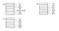
図2は、太陽電池裏面封止シート(V)を構成する黒色接着剤層(1)以外のフィルム(2)が白色顔料を含有する白色フィルム(2−1)を具備する、第1の態様を示す。
第1の態様として、さらに(a)〜(d)の態様を例示できる。
Hereinafter, various aspects of the solar cell backside sealing sheet (V) will be described with reference to the drawings.
FIG. 2 shows a first embodiment in which a film (2) other than the black adhesive layer (1) constituting the solar cell backside sealing sheet (V) comprises a white film (2-1) containing a white pigment. Indicates.
As the first mode, the modes (a) to (d) can be further exemplified.
図2の(a)に示す態様は、黒色接着剤層(1)/白色フィルム(2−1)/層間接着剤層(3)/金属酸化物もしくは非金属無機酸化物の蒸着層(4−1)/層間接着剤層(3)/他のフィルム(5−1)が、この順序で積層されてなるものである。 The mode shown in FIG. 2A is as follows: black adhesive layer (1) / white film (2-1) / interlayer adhesive layer (3) / deposition layer of metal oxide or nonmetal inorganic oxide (4- 1) Interlayer adhesive layer (3) / Other film (5-1) are laminated in this order.
図2の(b)の態様は、黒色接着剤層(1)/金属酸化物もしくは非金属無機酸化物の蒸着層(4−1)/層間接着剤層(3)/白色(2−1)/層間接着剤層(3)/他のフィルム(5−1)が、この順序で積層されてなるものである。 The mode of (b) of FIG. 2 is black adhesive layer (1) / deposited layer of metal oxide or non-metallic inorganic oxide (4-1) / interlayer adhesive layer (3) / white color (2-1). / Interlayer adhesive layer (3) / Other film (5-1) are laminated in this order.
図2の(c)に示す態様は、黒色接着剤層(1)/白色フィルム(2−1)/層間接着剤層(3)/金属酸化物もしくは非金属無機酸化物の蒸着層(4−1)または金属箔(4−2)/コーティング層(5−2)が、この順序で積層されてなるものである。 The mode shown in FIG. 2 (c) is as follows: black adhesive layer (1) / white film (2-1) / interlayer adhesive layer (3) / evaporated layer of metal oxide or non-metal inorganic oxide (4- 1) or metal foil (4-2) / coating layer (5-2) is laminated in this order.
図2の(d)の態様は、黒色接着剤層(1)/金属酸化物もしくは非金属無機酸化物の蒸着層(4−1)/層間接着剤層(3)/白色(2−1)/層間接着剤層(3)/コーティング層(5−2)が、この順序で積層されてなるものである。 The mode of (d) of FIG. 2 is black adhesive layer (1) / deposition layer (4-1) of metal oxide or non-metallic inorganic oxide / interlayer adhesive layer (3) / white color (2-1). / Interlayer adhesive layer (3) / coating layer (5-2) is laminated in this order.
図3は、太陽電池裏面封止シート(V)を構成する黒色接着剤層(1)以外のフィルム(2)が、透明フィルム(2−2)−aと、白色層(2−2)−bを具備する場合を示す。
図3に示す第2の態様として、さらに(a)〜(k)の態様を例示できる。
FIG. 3 shows that the film (2) other than the black adhesive layer (1) constituting the solar cell backside sealing sheet (V) is a transparent film (2-2) -a and a white layer (2-2)- The case where b is provided is shown.
As a 2nd aspect shown in FIG. 3, the aspect of (a)-(k) can be illustrated further.
図3の(a)に示す態様は、黒色接着剤層(1)/透明フィルム(2−2)−a/白色層(2−2)−b/金属酸化物もしくは非金属無機酸化物の蒸着層(4−1)または金属箔(4−2)/層間接着剤層(3)/他のフィルム(5−1)が、この順序で積層されてなるものである。
白色層(2−2)−bとしては、白色の層間接着剤層が例示できる。後述する図3の(b)、(c)、(d)、(e)、(j)の場合も同様である。
The embodiment shown in FIG. 3 (a) is a black adhesive layer (1) / transparent film (2-2) -a / white layer (2-2) -b / vapor deposition of metal oxide or non-metal inorganic oxide. The layer (4-1) or metal foil (4-2) / interlayer adhesive layer (3) / other film (5-1) is laminated in this order.
Examples of the white layer (2-2) -b include a white interlayer adhesive layer. The same applies to (b), (c), (d), (e), and (j) of FIG.
図3の(b)に示す態様は、黒色接着剤層(1)/金属酸化物もしくは非金属無機酸化物の蒸着層(4−1)/白色層(2−2)−b/透明フィルム(2−2)−a/層間接着剤層(3)/他のフィルム(5−1)が、この順序で積層されてなるものである。 The mode shown in (b) of FIG. 3 is as follows: black adhesive layer (1) / deposited layer of metal oxide or nonmetal inorganic oxide (4-1) / white layer (2-2) -b / transparent film ( 2-2) -a / interlayer adhesive layer (3) / other film (5-1) are laminated in this order.
図3の(c)に示す態様は、黒色接着剤層(1)/金属酸化物もしくは非金属無機酸化物の蒸着層(4−1)/白色層(2−2)−b/透明フィルム(2−2)−a/コーティング層(5−2)が、この順序で積層されてなるものである。 The mode shown in (c) of FIG. 3 is as follows: black adhesive layer (1) / deposited layer of metal oxide or non-metal inorganic oxide (4-1) / white layer (2-2) -b / transparent film ( 2-2) -a / coating layer (5-2) is laminated in this order.
図3の(d)に示す態様は、黒色接着剤層(1)/透明フィルム(2−2)−a/層間接着剤層(3)/金属酸化物もしくは非金属無機酸化物の蒸着層(4−1)/白色層(2−2)−b/他のフィルム(5−1)が、この順序で積層されてなるものである。 The mode shown in FIG. 3 (d) is as follows: black adhesive layer (1) / transparent film (2-2) -a / interlayer adhesive layer (3) / deposition layer of metal oxide or nonmetal inorganic oxide ( 4-1) / white layer (2-2) -b / other film (5-1) are laminated in this order.
図3の(e)に示す態様は、黒色接着剤層(1)/金属酸化物もしくは非金属無機酸化物の蒸着層(4−1)/層間接着剤層(3)/透明フィルム(2−2)−a/白色層(2−2)−b/他のフィルム(5−1)が、この順序で積層されてなるものである。 The mode shown in FIG. 3 (e) is as follows: black adhesive layer (1) / deposited layer of metal oxide or non-metallic inorganic oxide (4-1) / interlayer adhesive layer (3) / transparent film (2- 2) -a / white layer (2-2) -b / other film (5-1) are laminated in this order.
図3の(f)に示す態様は、黒色接着剤層(1)/金属酸化物もしくは非金属無機酸化物の蒸着層(4−1)/層間接着剤層(3)/透明フィルム(2−2)−a/層間接着剤(3)/白色層(2−2)−bが、この順序で積層されてなるものである。図3の(f)の場合の白色層(2−2)−bとしては、白色のいわゆる保護フィルムが例示できる。 The mode shown in FIG. 3 (f) is as follows: black adhesive layer (1) / deposited layer of metal oxide or non-metallic inorganic oxide (4-1) / interlayer adhesive layer (3) / transparent film (2- 2) -a / interlayer adhesive (3) / white layer (2-2) -b are laminated in this order. As the white layer (2-2) -b in the case of FIG. 3 (f), a white so-called protective film can be exemplified.
図3の(g)に示す態様は、黒色接着剤層(1)/金属酸化物もしくは非金属無機酸化物の蒸着層(4−1)/層間接着剤層(3)/透明フィルム(2−2)−a/白色層(2−2)−bが、この順序で積層されてなるものである。図3の(g)の場合の白色層(2−2)−bとしては、白色のコーティング層が例示できる。 The mode shown in FIG. 3 (g) is as follows: black adhesive layer (1) / deposited layer of metal oxide or non-metallic inorganic oxide (4-1) / interlayer adhesive layer (3) / transparent film (2- 2) -a / white layer (2-2) -b is laminated in this order. As the white layer (2-2) -b in the case of FIG. 3G, a white coating layer can be exemplified.
図3の(i)に示す態様は、黒色接着剤層(1)/透明フィルム(2−2)−a/層間接着剤層(3)/金属酸化物もしくは非金属無機酸化物の蒸着層(4−1)層間接着剤層(3)/白色層(2−2)−bが、この順序で積層されてなるものである。図3の(i)の場合の白色層(2−2)−bとしては、白色のいわゆる保護フィルムや、白色のコーティング層が例示できる。 The mode shown in (i) of FIG. 3 is as follows: black adhesive layer (1) / transparent film (2-2) -a / interlayer adhesive layer (3) / deposited layer of metal oxide or nonmetal inorganic oxide ( 4-1) The interlayer adhesive layer (3) / white layer (2-2) -b is laminated in this order. Examples of the white layer (2-2) -b in the case of (i) in FIG. 3 include a white so-called protective film and a white coating layer.
図3の(j)に示す態様は、黒色接着剤層(1)/透明フィルム(2−2)−a/白色層(2−2)−b/金属酸化物もしくは非金属無機酸化物の蒸着層(4−1)または金属箔(4−2)/コーティング層(5−2)が、この順序で積層されてなるものである。図3の(j)の場合の白色層(2−2)−bとしては、白色の層間接着剤が例示できる。 The mode shown in (j) of FIG. 3 is the deposition of black adhesive layer (1) / transparent film (2-2) -a / white layer (2-2) -b / metal oxide or non-metal inorganic oxide. The layer (4-1) or the metal foil (4-2) / coating layer (5-2) is laminated in this order. As the white layer (2-2) -b in the case of FIG. 3J, a white interlayer adhesive can be exemplified.
本発明で用いられる太陽電池裏面保護シートは、その他に図4〜図5に示すような態様とすることもできる。 In addition, the solar cell back surface protective sheet used in the present invention can be configured as shown in FIGS.
本発明で用いられる太陽電池裏面保護シートを構成する黒色接着剤層(1)について説明する。
本発明における黒色接着剤層(1)は、フィルム(2)と非受光面側封止剤層(IV)との接着性を向上するために設けられた層であり、650nm以下の波長の光を吸収するが、650〜900nm以上の光は透過し、吸収波長をもたない黒色顔料であるペリレンブラック顔料を含有することを特徴とする。このようなペリレンブラック顔料を含有することによって、人の目には黒色に映るにも関わらず、入射した近赤外線を吸収することなく通過することができる。そして、後述する太陽電池裏面保護シートを構成する他の層、即ちフィルム(2)の反射機能利用することにより、通過近赤外線を反射させ、発電に有効活用すると共に、太陽電池裏面保護シート自体及び太陽電池モジュールが高温になることを抑制することができる。
The black adhesive layer (1) which comprises the solar cell back surface protection sheet used by this invention is demonstrated.
The black adhesive layer (1) in the present invention is a layer provided to improve the adhesion between the film (2) and the non-light-receiving surface side sealant layer (IV), and has a wavelength of 650 nm or less. It is characterized in that it contains perylene black pigment, which is a black pigment that transmits light of 650 to 900 nm or more but does not have an absorption wavelength. By containing such a perylene black pigment, it is possible to pass through the incident near-infrared rays without absorbing it even though it appears black to human eyes. And by using the reflective function of the other layers constituting the solar cell back surface protective sheet described later, that is, the film (2), the near-infrared ray is reflected and effectively used for power generation, and the solar cell back surface protective sheet itself and It can suppress that a solar cell module becomes high temperature.
黒色接着剤層(1)は、種々の方法で設けることができる。例えば、
黒色接着剤をフィルムに塗工して、硬化性接着剤層を形成し、非受光面側封止剤(IV)と張り合わせる際に、前記硬化し接着剤層を硬化させ、黒色接着剤層(1)とすることができる。
あるいは、非受光面側封止剤(IV)と加熱下に付着し得る樹脂とペリレンブラック顔料を含有するフィルムを、接着剤を介して又は直にフィルム上に積層し、前記樹脂フィルムを接着剤層(1)として用いることもできる。後者の場合、例えば、ポリエチレン、ポリプロピレン等のポリオレフィン樹脂や、ポリフッ化ビニル、ポリフッ化ビニリデン等のフッ素系樹脂、エチレン−酢酸ビニル共重合体等にペリレンブラックを混合し、T−ダイ押出機等を用いてフィルム化することにより得ることができる。
The black adhesive layer (1) can be provided by various methods. For example,
A black adhesive is applied to the film to form a curable adhesive layer, and when the non-light-receiving surface side sealing agent (IV) is pasted, the above-mentioned curing is performed to cure the black adhesive layer. (1).
Alternatively, a non-light-receiving surface side sealing agent (IV), a film containing a resin capable of adhering under heating and a perylene black pigment are laminated on the film directly or via an adhesive, and the resin film is adhered to the adhesive. It can also be used as layer (1). In the latter case, for example, polyolefin resin such as polyethylene and polypropylene, fluorine resin such as polyvinyl fluoride and polyvinylidene fluoride, and ethylene-vinyl acetate copolymer are mixed with perylene black, and a T-die extruder is used. It can be obtained by using it as a film.
本発明の黒色接着剤層(1)はペリレンブラック顔料を含有することを特徴とする。
ペリレンブラック顔料としては、BASF(株)製のPaliogen BlackやLumogen Blackなどが挙げられる。
The black adhesive layer (1) of the present invention is characterized by containing a perylene black pigment.
Examples of the perylene black pigment include Paliogen Black and Lumogen Black manufactured by BASF Corporation.
ペリレンブラック顔料は、黒色接着剤層(1)100重量%中、0.5〜20重量%含有することが好ましく、1〜10重量%含有することがより好ましい。0.5重量%未満であると光学濃度が足りず、外観上黒色と認識されにくい。また、20重量%を超えると接着力の低下を招く可能性がある。さらに、ペリレンブラック顔料は黒色接着剤層(1)の厚さ1μm当たり、ペリレンブラック顔料を1〜10重量%含有することが好ましい。1重量%未満であると光学濃度が足りず、外観上黒色に色と認識されにくい。また、10重量%を超えると接着力の低下を招く可能性がある。 The perylene black pigment is preferably contained in an amount of 0.5 to 20% by weight and more preferably 1 to 10% by weight in 100% by weight of the black adhesive layer (1). If it is less than 0.5% by weight, the optical density is insufficient and it is difficult to be recognized as black in appearance. Moreover, when it exceeds 20 weight%, the fall of adhesive force may be caused. Further, the perylene black pigment preferably contains 1 to 10% by weight of the perylene black pigment per 1 μm of the thickness of the black adhesive layer (1). If it is less than 1% by weight, the optical density is insufficient, and it is difficult to recognize the color as black in appearance. Moreover, when it exceeds 10 weight%, the fall of adhesive force may be caused.
コーティング法により接着剤層(1)を設ける場合、水酸基を有する樹脂(B)を含有することが好ましい。水酸基を有する樹脂(B)の水酸価は、0.1〜50[mgKOH/g]であることが好ましく、さらには0.5〜30[mgKOH/g]であることが好ましい。水酸基が少ないと後述する硬化剤との反応点が少なくなり、架橋密度が低下することで耐湿熱性が悪化する。一方、水酸基が多いと架橋密度が増加し、硬化後の接着層(1)が硬くなることで充填剤との接着力が低下する。 When providing the adhesive layer (1) by a coating method, it is preferable to contain a hydroxyl group-containing resin (B). The hydroxyl value of the resin (B) having a hydroxyl group is preferably 0.1 to 50 [mg KOH / g], and more preferably 0.5 to 30 [mg KOH / g]. When there are few hydroxyl groups, the reaction point with the hardening | curing agent mentioned later will decrease, and the heat-and-moisture resistance will deteriorate because a crosslinking density falls. On the other hand, when there are many hydroxyl groups, a crosslinking density will increase and the adhesive layer (1) after hardening will harden, and the adhesive force with a filler will fall.
本発明において用いられる水酸基を有する樹脂(B)としては、ポリエステル系樹脂(B1)、ウレタン系樹脂、アクリル系樹脂が挙げられ、これらは単独または2種以上を使用できる。さらにこれらの樹脂が複合化したものも使用できる。 Examples of the resin (B) having a hydroxyl group used in the present invention include a polyester resin (B1), a urethane resin, and an acrylic resin, and these can be used alone or in combination of two or more. Further, a composite of these resins can be used.
本発明でいうポリエステル系樹脂(B1)とは、カルボン酸成分と水酸基成分とを反応(エステル化反応、エステル交換反応)させたポリエステル樹脂の他、水酸基を有するポリエステル樹脂にさらにイソシアネート化合物を反応させてなるポリエステルポリウレタン樹脂、さらにジアミン成分を反応させてなるポリエステルポリウレタンポリウレア樹脂などをも含む意である。 The polyester resin (B1) referred to in the present invention is a polyester resin obtained by reacting a carboxylic acid component and a hydroxyl component (esterification reaction, transesterification reaction), and further reacting an isocyanate compound with a polyester resin having a hydroxyl group. And polyester polyurethane polyurea resin obtained by reacting a diamine component.
ポリエステル系樹脂(B1)を構成するカルボン酸成分としては、安息香酸、p−tert−ブチル安息香酸、無水フタル酸、イソフタル酸、テレフタル酸、無水コハク酸、アジピン酸、アゼライン酸、テトレヒドロ無水フタル酸、ヘキサヒドロ無水フタル酸、無水マレイン酸、フマル酸、イタコン酸、テトラクロル無水フタル酸、1、4−シクロヘキサンジカルボン酸、無水トリメリット酸、メチルシクロヘキセントリカルボン酸無水物、無水ピロメリット酸、ε−カプロラクトン、脂肪酸が例示できる。
ポリエステル系樹脂(B1)を構成する水酸基成分としては、エチレングリコール、プロピレングリコール、1、3−ブチレングリコール、1、6−ヘキサンジオール、ジエチレングリコール、ジプロピレングリコール、ネオペンチルグリコール、トリエチレングリコール、3−メチルペンタンジオール、1、4−シクロヘキサンジメタノール等のジオール成分の他、グリセリン、トリメチロールエタン、トリメチロールプロパン、トリスヒドロキシメチルアミノメタン、ペンタエリスリトール、ジペンタエリスリトールなどの多官能アルコールが例示できる。
常法に従いこれらのカルボン酸成分と水酸基成分とを重合させて所定のポリエステル樹脂としたものが本発明で使用できる。
As the carboxylic acid component constituting the polyester resin (B1), benzoic acid, p-tert-butylbenzoic acid, phthalic anhydride, isophthalic acid, terephthalic acid, succinic anhydride, adipic acid, azelaic acid, tetrehydrophthalic anhydride , Hexahydrophthalic anhydride, maleic anhydride, fumaric acid, itaconic acid, tetrachlorophthalic anhydride, 1,4-cyclohexanedicarboxylic acid, trimellitic anhydride, methylcyclohexeric carboxylic anhydride, pyromellitic anhydride, ε-caprolactone, A fatty acid can be illustrated.
Examples of the hydroxyl group component constituting the polyester resin (B1) include ethylene glycol, propylene glycol, 1,3-butylene glycol, 1,6-hexanediol, diethylene glycol, dipropylene glycol, neopentyl glycol, triethylene glycol, 3-ethylene glycol, In addition to diol components such as methylpentanediol and 1,4-cyclohexanedimethanol, polyfunctional alcohols such as glycerin, trimethylolethane, trimethylolpropane, trishydroxymethylaminomethane, pentaerythritol, and dipentaerythritol can be exemplified.
According to a conventional method, those obtained by polymerizing these carboxylic acid component and hydroxyl group component into a predetermined polyester resin can be used in the present invention.
本発明でいうウレタン系樹脂とは、水酸基を有するポリエステル樹脂以外の水酸基成分とイソシアネート化合物を反応させてなるものである。
水酸基成分としては、ポリエチレングリコール、ポリプロピレングリコール、エチレンオキサイドやプロピレンオキサイドを付加したポリエーテル系ポリオール、アクリルポリオール、ポリブタジエン系ポリオールなどのポリマーポリオールなどが使用できる。
イソシアネート化合物としては、後述するポリイソシアネート化合物(C)と同様のものを例示できる。トリメチレンジイソシアネート(TDI)、ヘキサメチレンジイソシアネート(HDI)、メチレンビス(4、1−フェニレン)=ジイソシアネート(MDI)、3−イソシアネートメチル−3、5、5−トリメチルシクロヘキシルイソシアネート(IPDI)、キシリレンジイソシアネート(XDI)等のジイソシアネートや、これらジイソシアネートのトリメチロールプロパンアダクト体、これらジイソシアネートの三量体であるイソシアヌレート体、これらジイソシアネートのビューレット結合体、ポリメリックジイソシアネートなどが例示できる。
The urethane-based resin referred to in the present invention is obtained by reacting a hydroxyl component other than a polyester resin having a hydroxyl group with an isocyanate compound.
Examples of the hydroxyl component include polyethylene glycol, polypropylene glycol, polymer polyols such as polyether polyols added with ethylene oxide or propylene oxide, acrylic polyols, and polybutadiene polyols.
As an isocyanate compound, the thing similar to the polyisocyanate compound (C) mentioned later can be illustrated. Trimethylene diisocyanate (TDI), hexamethylene diisocyanate (HDI), methylene bis (4,1-phenylene) = diisocyanate (MDI), 3-isocyanate methyl-3,5,5-trimethylcyclohexyl isocyanate (IPDI), xylylene diisocyanate ( XDI), trimethylolpropane adducts of these diisocyanates, isocyanurates that are trimers of these diisocyanates, burette conjugates of these diisocyanates, polymeric diisocyanates, and the like.
アクリル系樹脂を構成するモノマーとしては、一般式(a)CH2=CR1−CO−OR2(R1は水素原子、もしくはメチル基、R2は水酸基もしくは炭素数1乃至20の置換基を有する炭化水素基を示す)で表されるアクリル酸、メタクリル酸、アクリル酸メチル、アクリル酸エチル、アクリル酸イソプロピル、アクリル酸n−ヘキシル、アクリル酸ブチル、アクリル酸2エチルヘキシル、アクリル酸4ヒドロキシブチル、アクリル酸ヒドロキシプロピル、メタクリル酸メチル、メタクリル酸エチル、メタクリル酸イソプロピル、メタクリル酸ブチル、メタクリル酸n−ヘキシル、メタクリル酸ラウリル、メタクリル酸2ヒドロキシエチル、メタクリル酸4ヒドロキシブチル、メタクリル酸ヒドロキシプロピル等が例示できる。更にはアクリルアミド、メタアクリルアミド、アクリルニトリル、メタアクリルニトリル、N−メチロールアクリルアミド、N−アルキロールアクリルアミド、ジアセトンアクリルアミド、ジアセトンメタクリルアミド、アクロレイン、メタアクロレイン、グリシジルメタクリレートなども反応性モノマーとして例示できる。常法に従いこれらのモノマーを共重合させて所定のアクリル樹脂としたものが本発明で使用できる。 As a monomer constituting the acrylic resin, the general formula (a) CH 2 = CR 1 —CO—OR 2 (R 1 is a hydrogen atom or a methyl group, R 2 is a hydroxyl group or a substituent having 1 to 20 carbon atoms). Acrylic acid, methacrylic acid, methyl acrylate, ethyl acrylate, isopropyl acrylate, n-hexyl acrylate, butyl acrylate, 2-ethylhexyl acrylate, 4-hydroxybutyl acrylate, Examples include hydroxypropyl acrylate, methyl methacrylate, ethyl methacrylate, isopropyl methacrylate, butyl methacrylate, n-hexyl methacrylate, lauryl methacrylate, 2-hydroxyethyl methacrylate, 4-hydroxybutyl methacrylate, hydroxypropyl methacrylate, etc. it can. Furthermore, acrylamide, methacrylamide, acrylonitrile, methacrylonitrile, N-methylol acrylamide, N-alkylol acrylamide, diacetone acrylamide, diacetone methacrylamide, acrolein, methacrolein, glycidyl methacrylate and the like can be exemplified as reactive monomers. Those obtained by copolymerizing these monomers according to a conventional method to obtain a predetermined acrylic resin can be used in the present invention.
本発明におけるポリエステル系樹脂(B1)としては、ガラス転移温度(Tg)が30〜100℃のものが好ましい。ガラス転移温度が30℃よりも低いと、接着剤層(1)の表面にタックが生じてブロッキングしやすくなったり、耐久性が低下したりする。100℃よりも高いと、接着の溶液粘度が高くなり、塗工性が低下する。 As a polyester-type resin (B1) in this invention, that whose glass transition temperature (Tg) is 30-100 degreeC is preferable. When the glass transition temperature is lower than 30 ° C., tackiness occurs on the surface of the adhesive layer (1), and it becomes easy to block or durability is lowered. When it is higher than 100 ° C., the solution viscosity of the adhesion is increased, and the coating property is lowered.
コーティング法により接着剤層(1)を設ける場合に用いられる接着剤は、水酸基を有する樹脂(B)の水酸基と反応し得る官能基を有する硬化剤を含有することが好ましい。
水酸基と反応し得る官能基を有する硬化剤としては、イソシアネート化合物が好ましく、硬化後に太陽電池モジュールを構成する接着層(1)の耐久性の点からイソシアネート化合物としては、ポリイソシアネート化合物(C)が好ましい。
The adhesive used when the adhesive layer (1) is provided by a coating method preferably contains a curing agent having a functional group capable of reacting with the hydroxyl group of the resin (B) having a hydroxyl group.
As the curing agent having a functional group capable of reacting with a hydroxyl group, an isocyanate compound is preferable. From the viewpoint of durability of the adhesive layer (1) constituting the solar cell module after curing, the isocyanate compound is a polyisocyanate compound (C). preferable.
本発明において用いられるポリイソシアネート化合物(C)としては、従来公知のものを使用することができ、例えば、芳香族ポリイソシアネート、鎖式もしくは環状脂肪族ポリイソシアネート、芳香脂肪族ポリイソシアネート等が挙げられる。芳香族ポリイソシアネートとしては、1、3−フェニレンジイソシアネート、4、4’−ジフェニルジイソシアネート、1、4−フェニレンジイソシアネート、4、4’−ジフェニルメタンジイソシアネート、2、4−トリレンジイソシアネート、2、6−トリレンジイソシアネート、4、4’−トルイジンジイソシアネート、2、4、6−トリイソシアネートトルエン、1、3、5−トリイソシアネートベンゼン、ジアニシジンジイソシアネート、4、4’−ジフェニルエーテルジイソシアネート、4、4’、4”−トリフェニルメタントリイソシアネート等を挙げることができる。 As the polyisocyanate compound (C) used in the present invention, conventionally known compounds can be used, and examples thereof include aromatic polyisocyanates, chain-type or cyclic aliphatic polyisocyanates, and araliphatic polyisocyanates. . Aromatic polyisocyanates include 1,3-phenylene diisocyanate, 4,4'-diphenyl diisocyanate, 1,4-phenylene diisocyanate, 4,4'-diphenylmethane diisocyanate, 2,4-tolylene diisocyanate, 2,6-triylene diisocyanate. Range isocyanate, 4,4'-toluidine diisocyanate, 2,4,6-triisocyanatetoluene, 1,3,5-triisocyanatebenzene, dianisidine diisocyanate, 4,4'-diphenyl ether diisocyanate, 4,4 ', 4 " -Triphenylmethane triisocyanate etc. can be mentioned.
鎖式脂肪族ポリイソシアネートとしては、トリメチレンジイソシアネート、テトラメチレンジイソシアネート、ヘキサメチレンジイソシアネート(HDI)、ペンタメチレンジイソシアネート、1、2−プロピレンジイソシアネート、2、3−ブチレンジイソシアネート、1、3−ブチレンジイソシアネート、ドデカメチレンジイソシアネート、2、4、4−トリメチルヘキサメチレンジイソシアネート等を挙げることができる。 Examples of chain aliphatic polyisocyanates include trimethylene diisocyanate, tetramethylene diisocyanate, hexamethylene diisocyanate (HDI), pentamethylene diisocyanate, 1,2-propylene diisocyanate, 2,3-butylene diisocyanate, 1,3-butylene diisocyanate, and dodeca. Examples include methylene diisocyanate, 2,4,4-trimethylhexamethylene diisocyanate and the like.
脂環族ポリイソシアネートとしては、3−イソシアネートメチル−3、5、5−トリメチルシクロヘキシルイソシアネート(IPDI)、1、3−シクロペンタンジイソシアネート、1、3−シクロヘキサンジイソシアネート、1、4−シクロヘキサンジイソシアネート、メチル−2、4−シクロヘキサンジイソシアネート、メチル−2、6−シクロヘキサンジイソシアネート、4、4’−メチレンビス(シクロヘキシルイソシアネート)、1、4−ビス(イソシアネートメチル)シクロヘキサン等を挙げることができる。 Examples of alicyclic polyisocyanates include 3-isocyanate methyl-3,5,5-trimethylcyclohexyl isocyanate (IPDI), 1,3-cyclopentane diisocyanate, 1,3-cyclohexane diisocyanate, 1,4-cyclohexane diisocyanate, methyl- 2,4-cyclohexane diisocyanate, methyl-2,6-cyclohexane diisocyanate, 4,4′-methylenebis (cyclohexyl isocyanate), 1,4-bis (isocyanatomethyl) cyclohexane, and the like.
芳香脂肪族ポリイソシアネートとしては、ω、ω’−ジイソシアネート−1、3−ジメチルベンゼン、ω、ω’−ジイソシアネート−1、4−ジメチルベンゼン、ω、ω’−ジイソシアネート−1、4−ジエチルベンゼン、1、4−テトラメチルキシリレンジイソシアネート、1、3−テトラメチルキシリレンジイソシアネート等を挙げることができる。 Examples of the araliphatic polyisocyanate include ω, ω′-diisocyanate-1,3-dimethylbenzene, ω, ω′-diisocyanate-1, 4-dimethylbenzene, ω, ω′-diisocyanate-1, 4-diethylbenzene, 4-tetramethylxylylene diisocyanate, 1,3-tetramethylxylylene diisocyanate, and the like.
また、上記ポリイソシアネートに加え、上記ポリイソシアネートとトリメチロールプロパン等のポリオール化合物とのアダクト体、上記ポリイソシアネートのビュレット体やイソシアヌレート体、更には上記ポリイソシアネートと公知のポリエーテルポリオールやポリエステルポリオール、アクリルポリオール、ポリブタジエンポリオール、ポリイソプレンポリオール等とのアダクト体等が挙げられる。 In addition to the polyisocyanate, an adduct of the polyisocyanate and a polyol compound such as trimethylolpropane, a burette or isocyanurate of the polyisocyanate, and further, the polyisocyanate and a known polyether polyol or polyester polyol, Examples thereof include adducts with acrylic polyol, polybutadiene polyol, polyisoprene polyol and the like.
これらポリイソシアネート化合物(C)の中でも、意匠性の観点から、低黄変型の脂肪族または脂環族のポリイソシアネートが好ましく、耐湿熱性の観点からは、イソシアヌレート体が好ましい。より具体的には、ヘキサメチレンジイソシアネート(HDI)のイソシアヌレート体、3−イソシアネートメチル−3、5、5−トリメチルシクロヘキシルイソシアネート(IPDI)のイソシアヌレート体が好ましい。 Among these polyisocyanate compounds (C), a low-yellowing type aliphatic or alicyclic polyisocyanate is preferable from the viewpoint of design, and an isocyanurate is preferable from the viewpoint of heat-and-moisture resistance. More specifically, hexamethylene diisocyanate (HDI) isocyanurate and 3-isocyanatomethyl-3,5,5-trimethylcyclohexyl isocyanate (IPDI) isocyanurate are preferred.
硬化剤としては、上記ポリイソシアネート化合物(C)の他に、周知のオキサゾリン化合物、例えば、2、5−ジメチル−2−オキサゾリン、2、2−(1、4−ブチレン)−ビス(2−オキサゾリン)またはヒドラジド化合物、たとえば、イソフタル酸ジヒドラジド、セバシン酸ジヒドラジド、アジピン酸ジヒドラジドを含むことができる。 As the curing agent, in addition to the polyisocyanate compound (C), known oxazoline compounds such as 2,5-dimethyl-2-oxazoline, 2,2- (1,4-butylene) -bis (2-oxazoline), for example. ) Or hydrazide compounds such as isophthalic acid dihydrazide, sebacic acid dihydrazide, adipic acid dihydrazide.
本発明において用いられるポリイソシアネート化合物(C)はブロック化ポリイソシアネート化合物であってもよい。 The polyisocyanate compound (C) used in the present invention may be a blocked polyisocyanate compound.
本発明に用いられる接着剤層(1)は、水酸基を有する樹脂(B)の水酸基の合計に対して、ポリイソシアネート化合物(C)中のイソシアネート基が、当量比にして1.0〜15.0になるように配合されることが好ましく、1.5〜10.0になるように配合されることがより好ましい。ポリイソシアネート化合物(C)が少ないと水酸基を有する樹脂(B)との反応がほとんど進まないので、太陽電池モジュールの耐久性向上が期待できない。ポリイソシアネート化合物(C)が多くなると硬化後の接着層(1)が硬くなりすぎるので、充填剤との初期接着力が低下する。 In the adhesive layer (1) used in the present invention, the isocyanate group in the polyisocyanate compound (C) is 1.0 to 15 in terms of an equivalent ratio with respect to the total number of hydroxyl groups of the resin (B) having hydroxyl groups. It is preferable to mix | blend so that it may be set to 0, and it is more preferable to mix | blend so that it may become 1.5-10.0. When the amount of the polyisocyanate compound (C) is small, the reaction with the hydroxyl group-containing resin (B) hardly proceeds, so that it is not expected to improve the durability of the solar cell module. If the polyisocyanate compound (C) increases, the cured adhesive layer (1) becomes too hard, and the initial adhesive force with the filler is reduced.
本発明に用いられる接着剤層(1)は、さらに樹脂成分を含有することができる。これら樹脂を含有することによって、接着剤層(1)の耐湿熱性を向上させることもできる。 The adhesive layer (1) used in the present invention can further contain a resin component. By containing these resins, the moisture and heat resistance of the adhesive layer (1) can be improved.
上記樹脂の具体例としては、アクリル樹脂、ウレタン樹脂、エポキシ樹脂、アルキド樹脂、ケトン樹脂、キシレン樹脂、オレフィン樹脂、ポリカーボネート樹脂、フェノール樹脂、フッ素樹脂等が挙げられる。 Specific examples of the resin include acrylic resin, urethane resin, epoxy resin, alkyd resin, ketone resin, xylene resin, olefin resin, polycarbonate resin, phenol resin, and fluorine resin.
本発明に用いられる接着剤層(1)は、さらに後述する有機系粒子、又は無機系粒子を含有することができる。これら粒子を含有することによって、接着剤層(1)表面のタックを低減することができる。 The adhesive layer (1) used in the present invention can further contain organic particles or inorganic particles described later. By containing these particles, tackiness on the surface of the adhesive layer (1) can be reduced.
有機系粒子の具体例としては、ポリオレフィン系ワックス、ポリメチルメタアクリレート樹脂、ポリスチレン樹脂、ナイロン樹脂、メラミン樹脂、グアナミン樹脂、フェノール樹脂、ユリア樹脂、シリコン樹脂、メタクリレート樹脂、アクリレート樹脂などのポリマー粒子、あるいは、セルロースパウダー、ニトロセルロースパウダー、木粉、古紙粉、籾殻粉、澱粉などが挙げられる。 Specific examples of organic particles include polyolefin wax, polymethyl methacrylate resin, polystyrene resin, nylon resin, melamine resin, guanamine resin, phenol resin, urea resin, silicon resin, methacrylate resin, acrylate resin, and other polymer particles, Alternatively, cellulose powder, nitrocellulose powder, wood powder, waste paper powder, rice husk powder, starch and the like can be mentioned.
前記ポリマー粒子は、乳化重合法、懸濁重合法、分散重合法、ソープフリー重合法、シード重合法、マイクロサスペンジョン重合法、などの重合法により得ることができる。また、前記有機系粒子は、その特性を損なわない程度に不純物を含んでいてもよい。また、粒子の形状は、粉末状、粒状、顆粒状、平板状、繊維状、など、どのような形状であってもよい。 The polymer particles can be obtained by a polymerization method such as an emulsion polymerization method, a suspension polymerization method, a dispersion polymerization method, a soap-free polymerization method, a seed polymerization method, or a microsuspension polymerization method. The organic particles may contain impurities to the extent that the characteristics are not impaired. The shape of the particles may be any shape such as powder, granule, granule, flat plate, and fiber.
無機粒子の具体例としては、ガラス繊維、ガラス粉末、ガラスビーズ、クレー、ワラスナイト、酸化鉄、酸化アンチモン、リトポン、軽石粉、硫酸アルミニウム、ケイ酸ジルコニウム、ドロマイト、砂鉄などを含有する無機系粒子が挙げられる。 Specific examples of the inorganic particles include inorganic particles containing glass fiber, glass powder, glass beads, clay, wollastonite, iron oxide, antimony oxide, lithopone, pumice powder, aluminum sulfate, zirconium silicate, dolomite, iron sand and the like. Can be mentioned.
また、前記無機系粒子は、その特性を損なわない程度に不純物を含んでいてもよい。また、粒子の形状は、粉末状、粒状、顆粒状、平板状、繊維状、など、どのような形状であってもよい。 Moreover, the said inorganic type particle | grain may contain the impurity to such an extent that the characteristic is not impaired. The shape of the particles may be any shape such as powder, granule, granule, flat plate, and fiber.
本発明に用いられる接着剤層(1)は、水酸基を含有する樹脂(B)に対して、上記各種粒子を0.01〜30重量部含有することが好ましく、0.1〜10重量部含有することがより好ましい。上記各種粒子が少ないと接着剤層(1)表面のタックを充分に低減することができない。一方、上記各種粒子が多くなると、接着剤層(1)と充填剤との密着を阻害し、接着力の低下を招く可能性がある。 The adhesive layer (1) used in the present invention preferably contains 0.01 to 30 parts by weight of the above various particles with respect to the resin (B) containing a hydroxyl group, and contains 0.1 to 10 parts by weight. More preferably. When there are few said various particle | grains, the adhesive layer (1) surface tack cannot fully be reduced. On the other hand, when the above-mentioned various particles increase, the adhesion between the adhesive layer (1) and the filler may be hindered, resulting in a decrease in adhesive strength.
次に本発明において用いられる太陽電池用裏面保護シートを構成するフィルム(2)について説明する。
フィルム(2)は700〜1200nmの赤外線の反射率が60〜100%であることを特徴とし、80%以上であることが好ましく、さらには90%以上であることが好ましい。ペリレンブラック顔料が吸収せず透過した近赤外領域の光が、フィルム(2)により反射されることにより、遮熱効果と光電変換効率向上の効果が生じる。
Next, the film (2) which comprises the back surface protection sheet for solar cells used in this invention is demonstrated.
The film (2) is characterized by having an infrared reflectance of 700 to 1200 nm of 60 to 100%, preferably 80% or more, and more preferably 90% or more. The light in the near-infrared region that is transmitted without being absorbed by the perylene black pigment is reflected by the film (2), thereby producing a heat shielding effect and an effect of improving the photoelectric conversion efficiency.
本発明におけるフィルム(2)は、白色顔料を含有する白色フィルム(2−1)を具備するか、透明フィルム(2−2)−aと白色層(2−2)−bとを具備するものである。
白色フィルム(2−1)は、フィルム(2)が上記のような近赤外線反射機能を有すれば、多層構成のフィルム(2)のどの位置に配されても良いが、反射効率を考慮すると黒色接着剤層(1)と直に接する位置に配されることが好ましい。
The film (2) in the present invention comprises a white film (2-1) containing a white pigment, or comprises a transparent film (2-2) -a and a white layer (2-2) -b. It is.
The white film (2-1) may be arranged in any position of the multilayer film (2) as long as the film (2) has the near infrared reflection function as described above. It is preferable to be disposed at a position in direct contact with the black adhesive layer (1).
白色フィルム(2−1)として用いられる樹脂フィルムとしては、例えば、ポリエチレンテレフタレート、ポリブチレンテレフタレート、ポリナフタレンテレフタレートなどのポリエステル系樹脂フィルム、ポリエチレン、ポリプロピレン、ポリシクロペンタジエンなどのオレフィンフィルム、ポリフッ化ビニル、ポリフッ化ビニリデンフィルム、ポリテトラフルオロエチレンフィルム、エチレン‐テトラフルオロエチレン共重合体フィルムなどのフッ素系フィルム、アクリルフィルム、トリアセチルセルロースフィルム、を用いることができる。コストの観点からポリエステル系樹脂フィルムであることが望ましい。 Examples of the resin film used as the white film (2-1) include polyester resin films such as polyethylene terephthalate, polybutylene terephthalate, and polynaphthalene terephthalate, olefin films such as polyethylene, polypropylene, and polycyclopentadiene, polyvinyl fluoride, Fluorine-based films such as polyvinylidene fluoride films, polytetrafluoroethylene films, and ethylene-tetrafluoroethylene copolymer films, acrylic films, and triacetyl cellulose films can be used. A polyester resin film is desirable from the viewpoint of cost.
白色フィルム(2−1)は、白色顔料または体質顔料を含有することで白色になり、反射機能を有することができる。これらの顔料を含有することによって、フィルム(2−1)に入射した光が表面あるいは内部で反射し、太陽電池素子(III)に入射する効率が高くなる。 A white film (2-1) becomes white by containing a white pigment or an extender, and can have a reflective function. By containing these pigments, the light incident on the film (2-1) is reflected on the surface or inside thereof, and the efficiency of entering the solar cell element (III) is increased.
白色顔料の具体例としては、酸化チタン、酸化亜鉛、鉛白、硫化亜鉛などが挙げられる。
着色力、耐候性、コストの観点から酸化チタンが望ましい。
Specific examples of the white pigment include titanium oxide, zinc oxide, white lead, and zinc sulfide.
Titanium oxide is desirable from the viewpoint of coloring power, weather resistance, and cost.
体質顔料の具体例としては、マグネシウム、カルシウム、バリウム、亜鉛、ジルコニウム、モリブデン、ケイ素、アンチモン、チタン、などの金属の酸化物、水酸化物、硫酸塩、炭酸塩、ケイ酸塩、などを含有する無機系粒子が挙げられる。さらに詳細な具体例としては、シリカゲル、酸化アルミニウム、水酸化カルシウム、炭酸カルシウム、酸化マグネシウム、水酸化マグネシウム、炭酸マグネシウム、酸化亜鉛、鉛酸化物、珪藻土、ゼオライト、アルミノシリケート、タルク、ホワイトカーボン、マイカなどが挙げられる。 Specific examples of extender pigments include magnesium, calcium, barium, zinc, zirconium, molybdenum, silicon, antimony, titanium, and other metal oxides, hydroxides, sulfates, carbonates, silicates, etc. Inorganic particles to be used. Further specific examples include silica gel, aluminum oxide, calcium hydroxide, calcium carbonate, magnesium oxide, magnesium hydroxide, magnesium carbonate, zinc oxide, lead oxide, diatomaceous earth, zeolite, aluminosilicate, talc, white carbon, mica Etc.
白色フィルム(2−1)は、発泡ポリエステルフィルムであることが好ましい。発泡、即ち、気泡も含有しているため、空気層と白色顔料との屈折率差によって近赤外領域の反射率が大きくなる。
気泡を含有しない白色顔料含有白色フィルム(2−1)と、気泡を含有する発泡ポリエウステルフィルムを積層して用いることもできる。
The white film (2-1) is preferably a foamed polyester film. Since foaming, that is, bubbles are also included, the reflectance in the near infrared region is increased by the difference in refractive index between the air layer and the white pigment.
A white pigment-containing white film (2-1) containing no air bubbles and a foamed polyester film containing air bubbles can be laminated and used.
太陽電池裏面保護シート(V)は、さらに金属箔、あるいは金属酸化物もしくは非金属無機酸化物の蒸着層を具備することが好ましい。水蒸気バリア性付与機能を担うこれら金属箔等は、白色フィルム(2−1)の黒色接着剤層(1)を担持してない側に位置する。 The solar cell back surface protective sheet (V) preferably further comprises a metal foil, or a vapor-deposited layer of metal oxide or non-metal inorganic oxide. These metal foils and the like responsible for the water vapor barrier property-providing function are located on the side of the white film (2-1) that does not carry the black adhesive layer (1).
白色フィルム(2−1)と金属箔とは接着剤層を介して積層されることができる。
金属箔としては、アルミニウム箔、鉄箔、亜鉛合板などを使用することができ、これらの中でも、耐腐食性の観点から、アルミニウム箔が好ましく、厚みは10μmから100μmであることが好ましく、更に好ましくは20μmから50μmであることが好ましい。
両者の積層には、従来公知の種々の接着剤を用いることができる。
The white film (2-1) and the metal foil can be laminated via an adhesive layer.
As the metal foil, aluminum foil, iron foil, zinc plywood and the like can be used. Among these, aluminum foil is preferable from the viewpoint of corrosion resistance, and the thickness is preferably 10 μm to 100 μm, and more preferably. Is preferably 20 μm to 50 μm.
Conventionally known various adhesives can be used for the lamination of the two.
蒸着層は、白色フィルム(2−1)の一方の面に設けられる。接着剤層を介して片面蒸着ポリエステルフィルム同士を積層したものや、あるいは片面蒸着ポリエステルフィルムと他の蒸着フィルムとを接着剤層を介して積層したものも、用いることができる。
蒸着される金属酸化物もしくは非金属無機酸化物としては、例えば、ケイ素、アルミニウム、マグネシウム、カルシウム、カリウム、スズ、ナトリウム、ホウ素、チタン、鉛、ジルコニウム、イットリウムなどの酸化物が使用できる。また、アルカリ金属、アルカリ土類金属のフッ化物なども使用することができ、これらは単独もしくは組み合わせて使用することができる。
これらの金属酸化物もしくは非金属無機酸化物は、従来公知の真空蒸着、イオンプレーティング、スパッタリングなどのPVD方式や、プラズマCVD、マイクロウェーブCVDなどのCVD方式を用いて蒸着することができる。
The vapor deposition layer is provided on one surface of the white film (2-1). What laminated | stacked single-sided vapor deposition polyester films via the adhesive bond layer, or what laminated | stacked single-side vapor deposition polyester film and another vapor deposition film via an adhesive bond layer can also be used.
Examples of the metal oxide or non-metal inorganic oxide to be deposited include oxides such as silicon, aluminum, magnesium, calcium, potassium, tin, sodium, boron, titanium, lead, zirconium, and yttrium. Alkali metal and alkaline earth metal fluorides can also be used, and these can be used alone or in combination.
These metal oxides or non-metal inorganic oxides can be deposited using a conventionally known PVD method such as vacuum deposition, ion plating, sputtering, or the like, or a CVD method such as plasma CVD or microwave CVD.
太陽電池裏面保護シート(V)は、耐候性付与のためのフッ素樹脂含有層などをさらに具備することができる。耐候性付与層は、水蒸気バリア性付与機能を担う上記金属箔等よりもさらに外側、即ち白色フィルム(2−1)の設けられている側とは反対側に位置することができる。
水蒸気バリア性付与層や耐候性付与層は、黒色接着剤層(1)の形成に先んじて白色フィルム(2−1)に設けられていることが好ましい。
The solar cell back surface protective sheet (V) can further include a fluororesin-containing layer for imparting weather resistance. The weather resistance imparting layer can be located on the outer side, i.e., the side opposite to the side where the white film (2-1) is provided, than the metal foil or the like responsible for the water vapor barrier property imparting function.
It is preferable that the water vapor barrier property-imparting layer and the weather resistance-imparting layer are provided on the white film (2-1) prior to the formation of the black adhesive layer (1).
透明フィルム(2−2)−aと白色層(2−2)−bとを具備する積層フィルムも白色フィルムを具備する場合と同様に、太陽電池裏面保護シート(V)を形成する。
白色層(2−2)−bとしては、透明フィルムと蒸着層または耐候性付与層を接着するのに用いられる層間接着剤に、白色顔料や体質顔料を加え白色にした白色接着剤層や、多くの場合、太陽電池裏面保護シート(V)の最非受光面側に位置する耐候性付与層を白色にした白色耐候性付与層などが挙げられる。
白色の耐候性付与層は、耐候性に優れる白色のコーティング剤から形成することもできるし、接着剤を用いて耐候性に優れる白色のフィルムを貼り合せ、耐候性付与層とすることもできる。
白色層(2−2)−bを用いることで、受光面側から黒色接着剤層(1)を透過した近赤外線を白色層(2−2)−bが反射し、受光面側に入射させることができる。
Similarly to the case where the laminated film including the transparent film (2-2) -a and the white layer (2-2) -b also includes the white film, the solar cell back surface protective sheet (V) is formed.
As the white layer (2-2) -b, a white adhesive layer made white by adding a white pigment or an extender pigment to an interlayer adhesive used for bonding a transparent film and a vapor deposition layer or a weather resistance imparting layer, In many cases, a white weather resistance imparting layer in which the weather resistance imparting layer located on the most non-light-receiving surface side of the solar cell back surface protective sheet (V) is white is exemplified.
The white weather resistance imparting layer can be formed from a white coating agent excellent in weather resistance, or a white film excellent in weather resistance can be bonded using an adhesive to form a weather resistance imparting layer.
By using the white layer (2-2) -b, the white layer (2-2) -b reflects near-infrared light that has passed through the black adhesive layer (1) from the light receiving surface side and is incident on the light receiving surface side. be able to.
次に、黒色接着剤層(1)をコーティング法により、白色フィルム(2−1)上にもしくは透明フィルム(2−2)−a上に形成する方法について説明する。
白色フィルム(2−1)上にもしくは透明フィルム(2−2)−a上に、あるいは白色フィルム(2−1)上にもしくは透明フィルム(2−2)−a上に水蒸気バリア性付与層(4)や耐候性付与層(5)を積層してなる多層フィルム上に、黒色接着剤を塗工し、有機溶剤等の揮発性生成を揮発・乾燥させ、黒色接着剤層(1)を形成し、本発明の太陽電池用裏面保護シートを得ることができる。
Next, a method for forming the black adhesive layer (1) on the white film (2-1) or the transparent film (2-2) -a by a coating method will be described.
A water vapor barrier property-imparting layer on the white film (2-1) or on the transparent film (2-2) -a, or on the white film (2-1) or on the transparent film (2-2) -a ( 4) On the multilayer film formed by laminating the weather resistance layer (5), a black adhesive is applied, and volatile products such as organic solvents are volatilized and dried to form a black adhesive layer (1). And the back surface protection sheet for solar cells of this invention can be obtained.
本発明において、黒色接着剤を塗布する方法としては、従来公知の方法を用いることができ、具体的にはコンマコーティング、グラビアコーティング、リバースコーティング、ロールコーティング、リップコーティング、スプレーコーティングが例示できる。本発明では、これらの方法で接着剤を塗布し、加熱乾燥により溶剤を揮散させる工程を塗工と称する。
形成される黒色接着剤層(1)の厚みは0.1〜10μmである。
In the present invention, a conventionally known method can be used as a method for applying the black adhesive, and specific examples include comma coating, gravure coating, reverse coating, roll coating, lip coating, and spray coating. In this invention, the process of apply | coating an adhesive agent by these methods and volatilizing a solvent by heat drying is called coating.
The thickness of the black adhesive layer (1) to be formed is 0.1 to 10 μm .
次に本発明の太陽電池モジュールの製造方法について説明する。
本発明の太陽電池モジュールは、太陽電池の受光面側に位置する太陽電池表面封止シート(I)と、太陽電池の受光面側に位置する封止材層(II)、太陽電池素子(III)と、太陽電池の非受光面側に位置する封止材層(IV)と、詳述した太陽電池用裏面保護シート(V)を必須の構成層とし、前記非受光面側封止材層(IV)に太陽電池裏面封止シート(V)の黒色接着剤層(1)が接するように、太陽電池裏面封止シート(V)を積層することによって、得ることができる。非受光面側封止材層(IV)と太陽電池用裏面保護シート(V)とを積層する際、減圧下に両者を接触させ、次いで加熱・加圧下に重ね合わせることによって得ることができる。
黒色接着剤層(1)が熱硬化性の場合、常圧に戻した後、さらに高温条件下に置いて、黒色接着剤層(1)の硬化を進行させることもできる。
Next, the manufacturing method of the solar cell module of this invention is demonstrated.
The solar cell module of the present invention includes a solar cell surface sealing sheet (I) positioned on the light receiving surface side of the solar cell, a sealing material layer (II) positioned on the light receiving surface side of the solar cell, and a solar cell element (III ), The sealing material layer (IV) located on the non-light-receiving surface side of the solar cell, and the back surface protection sheet (V) for solar cells described in detail as essential constituent layers, and the non-light-receiving surface side sealing material layer It can obtain by laminating | stacking a solar cell back surface sealing sheet (V) so that the black adhesive layer (1) of a solar cell back surface sealing sheet (V) may contact (IV). When laminating the non-light-receiving surface side sealing material layer (IV) and the solar cell back surface protective sheet (V), they can be obtained by bringing them into contact with each other under reduced pressure and then superposing them under heating and pressure.
When the black adhesive layer (1) is thermosetting, the black adhesive layer (1) can be cured by returning to normal pressure and then placing it under a higher temperature condition.
以下、実施例により、本発明をさらに詳細に説明する。なお、実施例中、部は重量部を、%は重量%をそれぞれ示す。 Hereinafter, the present invention will be described in more detail with reference to examples. In the examples, “part” means “part by weight” and “%” means “% by weight”.
<ポリエステル樹脂溶液B1>
テレフタル酸ジメチル99.6部、エチレングリコール92.2部、ネオペンチルグリコール72.2部、および酢酸亜鉛0.02部を反応缶に仕込み、窒素気流下で攪拌しながら160〜210℃に加熱し、エステル交換反応を行なった。理論量の97%のメタノールが留出した後、イソフタル酸77.5部、アゼライン酸166.9部を仕込み、160〜240℃に加熱し、エステル化反応を行なった。このまま反応缶を徐々に1〜2トールまで減圧し、酸価が0.8mgKOH/g以下となったところで減圧下での反応を停止し、数平均分子量が41、000、水酸基価が3.2(mgKOH/g)、酸価が0.7(mgKOH/g)、Tgが−10℃のポリエステルポリオールを得、酢酸エチルで希釈して、固形分50%のポリエステル樹脂溶液B1−1を得た。
<Polyester resin solution B1>
Charge 99.6 parts of dimethyl terephthalate, 92.2 parts of ethylene glycol, 72.2 parts of neopentyl glycol, and 0.02 part of zinc acetate, and heat to 160-210 ° C. with stirring under a nitrogen stream. A transesterification reaction was carried out. After 97% of the theoretical amount of methanol was distilled, 77.5 parts of isophthalic acid and 166.9 parts of azelaic acid were charged and heated to 160 to 240 ° C. to carry out an esterification reaction. The reaction vessel was gradually reduced in pressure to 1 to 2 Torr, and when the acid value became 0.8 mgKOH / g or less, the reaction under reduced pressure was stopped. The number average molecular weight was 41,000 and the hydroxyl value was 3.2. (MgKOH / g), a polyester polyol having an acid value of 0.7 (mgKOH / g) and Tg of −10 ° C. was obtained and diluted with ethyl acetate to obtain a polyester resin solution B1-1 having a solid content of 50%. .
別途、ポリエステル樹脂「バイロン200」(東洋紡(株)、数平均分子量17、000、水酸基価が6(mgKOH/g)、酸価が2(mgKOH/g)以下、Tg:67℃)をメチルエチルケトンに溶解し、固形分50%のポリエステル樹脂溶液B1−2を得た。 Separately, polyester resin “Byron 200” (Toyobo Co., Ltd., number average molecular weight 17,000, hydroxyl value 6 (mgKOH / g), acid value 2 (mgKOH / g) or less, Tg: 67 ° C.) to methyl ethyl ketone. It melt | dissolved and obtained polyester resin solution B1-2 of 50% of solid content.
次いで、前記ポリエステル樹脂溶液B1−1と前記ポリエステル樹脂溶液B1−2とを重量比1:1で混合し、固形分50重量%のポリエステル樹脂溶液B1を得た。
ポリエステル樹脂溶液B1中のポリエステル樹脂は、水酸基価が4.6(mgKOH/g)、酸価が0.8(mgKOH/g)、Tgが28℃であった。
Next, the polyester resin solution B1-1 and the polyester resin solution B1-2 were mixed at a weight ratio of 1: 1 to obtain a polyester resin solution B1 having a solid content of 50% by weight.
The polyester resin in the polyester resin solution B1 had a hydroxyl value of 4.6 (mgKOH / g), an acid value of 0.8 (mgKOH / g), and a Tg of 28 ° C.
なお、数平均分子量、ガラス転移温度、酸価、水酸基価は、下記に記述するようにして測定した。 The number average molecular weight, glass transition temperature, acid value, and hydroxyl value were measured as described below.
<数平均分子量(Mn)の測定>
Mnの測定はGPC(ゲルパーミエーションクロマトグラフィー)を用いた。GPCは溶媒(THF;テトラヒドロフラン)に溶解した物質をその分子サイズの差によって分離定量する液体クロマトグラフィーであり、数平均分子量(Mn)の決定はポリスチレン換算で行った。
<Measurement of number average molecular weight (Mn)>
For the measurement of Mn, GPC (gel permeation chromatography) was used. GPC is liquid chromatography in which a substance dissolved in a solvent (THF; tetrahydrofuran) is separated and quantified by the difference in molecular size, and the number average molecular weight (Mn) is determined in terms of polystyrene.
<ガラス転移温度(Tg)の測定>
ガラス転移温度の測定は、示差走査熱量測定(DSC)により求めた。
アルミニウムパンに試料約10mgを秤量してDSC装置にセットし(リファレンス:試料を入れていない同タイプのアルミニウムパンとした。)、300℃の温度で5分間加熱した後、液体窒素を用いて−120℃まで急冷処理した。その後10℃/分で昇温し、得られたDSCチャートからガラス転移温度(Tg)を算出した(単位:℃)。
<Measurement of glass transition temperature (Tg)>
The glass transition temperature was measured by differential scanning calorimetry (DSC).
About 10 mg of sample was weighed in an aluminum pan and set in a DSC apparatus (reference: the same type of aluminum pan without sample). After heating at 300 ° C. for 5 minutes, using liquid nitrogen − Rapid cooling was performed to 120 ° C. Thereafter, the temperature was raised at 10 ° C./min, and the glass transition temperature (Tg) was calculated from the obtained DSC chart (unit: ° C.).
<水酸基価(OHV)の測定>
共栓三角フラスコ中に試料(樹脂の溶液:約50%)約1gを精密に量り採り、トルエン/エタノール(容量比:トルエン/エタノール=2/1)混合液100mlを加えて溶解する。更にアセチル化剤(無水酢酸25gをピリジンで溶解し、容量100mlとした溶液)を正確に5ml加え、約1時間攪拌した。これに、フェノールフタレイン試液を指示薬として加え、30秒間持続する。その後、溶液が淡紅色を呈するまで0.1Nアルコール性水酸化カリウム溶液で滴定する。
水酸基価は次式により求めた。水酸基価は樹脂の乾燥状態の数値とした(単位:mgKOH/g)。
<Measurement of hydroxyl value (OHV)>
About 1 g of a sample (resin solution: about 50%) is accurately weighed in a stoppered Erlenmeyer flask, and 100 ml of a toluene / ethanol (volume ratio: toluene / ethanol = 2/1) mixed solution is added and dissolved. Further, 5 ml of an acetylating agent (a solution in which 25 g of acetic anhydride was dissolved in pyridine to make a volume of 100 ml) was added and stirred for about 1 hour. To this, phenolphthalein reagent is added as an indicator and lasts for 30 seconds. Thereafter, the solution is titrated with a 0.1N alcoholic potassium hydroxide solution until the solution becomes light red.
The hydroxyl value was determined by the following formula. The hydroxyl value was a numerical value in the dry state of the resin (unit: mgKOH / g).
水酸基価(mgKOH/g)=[{(b−a)×F×28.25}/S]/(不揮発分濃度/100)+D
ただし、S:試料の採取量(g)
a:0.1Nアルコール性水酸化カリウム溶液の消費量(ml)
b:空実験の0.1Nアルコール性水酸化カリウム溶液の消費量(ml)
F:0.1Nアルコール性水酸化カリウム溶液の力価
D:酸価(mgKOH/g)
Hydroxyl value (mgKOH / g) = [{(ba) × F × 28.25} / S] / (Nonvolatile content concentration / 100) + D
Where S: Amount of sample collected (g)
a: Consumption of 0.1N alcoholic potassium hydroxide solution (ml)
b: Consumption of 0.1N alcoholic potassium hydroxide solution in the empty experiment (ml)
F: Potency of 0.1N alcoholic potassium hydroxide solution D: Acid value (mgKOH / g)
<アクリル樹脂溶液B2>
冷却管、撹拌装置、温度計、窒素導入管を備えた4つ口フラスコに、メチルメタクリレート40部、n−ブチルメタクリレート30部、2−エチルヘキシルメタクリレート28部、2−ヒドロキシエチルメタクリレート1部、トルエン100部を仕込み、窒素雰囲気下で撹拌しながら80℃まで昇温し、アゾビスイソブチロニトリルを0.15部加えて2時間重合反応を行い、次に、アゾビスイソブチロニトリルを0.07部加えてさらに2時間重合反応を行い、更に0.07部のアゾビスイソブチロニトリルを加えてさらに2時間重合反応を行い、数平均分子量が25、000、水酸基価が4.4(mgKOH/g)、酸価が0(mgKOH/g)、Tgが39℃、固形分50%のアクリル樹脂溶液B2を得た。
<Acrylic resin solution B2>
In a four-necked flask equipped with a cooling tube, a stirrer, a thermometer, and a nitrogen introduction tube, 40 parts of methyl methacrylate, 30 parts of n-butyl methacrylate, 28 parts of 2-ethylhexyl methacrylate, 1 part of 2-hydroxyethyl methacrylate, 100 of toluene The temperature was raised to 80 ° C. with stirring in a nitrogen atmosphere, 0.15 parts of azobisisobutyronitrile was added, and the polymerization reaction was carried out for 2 hours. 07 parts were added and the polymerization reaction was further carried out for 2 hours, 0.07 parts of azobisisobutyronitrile was further added and the polymerization reaction was further carried out for 2 hours, and the number average molecular weight was 25,000 and the hydroxyl value was 4.4 ( mgKOH / g), an acid value of 0 (mgKOH / g), Tg of 39 ° C., and an acrylic resin solution B2 having a solid content of 50% were obtained.
<ポリエステル樹脂溶液B3>
ジエチレングリコール117部、ネオペンチルグリコール319部、イソフタル酸192部、テレフタル酸188部、アジピン酸214部を反応缶に仕込み、窒素気流下で攪拌しながら160〜240℃に加熱し、エステル化反応を行なった。このまま反応缶を徐々に1〜2トールまで減圧し、酸価が1mgKOH/g以下となったところで減圧下での反応を停止し、数平均分子量が10、000、水酸基価が19(mgKOH/g)、酸価が0.9(mgKOH/g)、Tgが0℃のポリエステル樹脂を得、酢酸エチルで希釈して、固形分50%のポリエステル樹脂溶液B3を得た。
<Polyester resin solution B3>
117 parts of diethylene glycol, 319 parts of neopentyl glycol, 192 parts of isophthalic acid, 188 parts of terephthalic acid, and 214 parts of adipic acid are charged into a reaction can and heated to 160-240 ° C. with stirring under a nitrogen stream to carry out an esterification reaction. It was. The reaction vessel was gradually reduced in pressure to 1 to 2 Torr, and when the acid value became 1 mgKOH / g or less, the reaction was stopped under reduced pressure, the number average molecular weight was 10,000, and the hydroxyl value was 19 (mgKOH / g ), A polyester resin having an acid value of 0.9 (mg KOH / g) and a Tg of 0 ° C. was obtained and diluted with ethyl acetate to obtain a polyester resin solution B3 having a solid content of 50%.
<硬化剤溶液>
MEKオキシムでブロックされた、イソホロンジイソシアネートの三量体と、MEKオキシムでブロックされた、ヘキサメチレンジイソシアネートの三量体を、重量比1:1で混合し、酢酸エチルで希釈して固形分50%の樹脂溶液としたものを硬化剤溶液とする。
<Curing agent solution>
A trimer of isophorone diisocyanate blocked with MEK oxime and a trimer of hexamethylene diisocyanate blocked with MEK oxime were mixed at a weight ratio of 1: 1 and diluted with ethyl acetate to give a solid content of 50%. The resin solution is used as a curing agent solution.
<接着剤の調整>
黒色顔料(A)、酸価を有する樹脂溶液(B)、硬化剤溶液(C)、顔料を表1に示す組成にて混合し、接着剤1〜7を得た。
各黒色接着剤を東洋紡(株)製、テトロンS、厚み188μm、以下「透明基材A」という)に塗工、乾燥し、10μmの接着剤層を作成し、各接着剤層について、分光光度計V−570(日本分光製)を用いて波長600〜1200nmの範囲の透過率を測定した。
<Adhesive adjustment>
The black pigment (A), the resin solution (B) having an acid value, the curing agent solution (C), and the pigment were mixed in the composition shown in Table 1 to obtain
Each black adhesive was applied to Toyobo Co., Ltd., Tetron S, thickness 188 μm, hereinafter referred to as “transparent substrate A”) and dried to prepare a 10 μm adhesive layer. Using a total V-570 (manufactured by JASCO Corporation), the transmittance in the wavelength range of 600 to 1200 nm was measured.
具体的な太陽電池裏面保護シートの例として、表2、3に積層構成を例示するが、その積層構成に限るものでは無い。 As an example of a specific solar cell back surface protective sheet, although a laminated structure is illustrated in Tables 2 and 3, it is not limited to the laminated structure.
[実施例1]
<太陽電池用裏面保護シートの作成>
白色顔料含有白色ポリエステルフィルム(東レ(株)製、ルミラーE20、厚み50μm、以下「白基材B」という)の一方の面にポリエステル接着剤「ダイナレオVA−3020/HD−701」(東洋インキ製造(株)製、配合比100/7、以下同)をグラビアコーターによって塗布し、溶剤を乾燥させ、塗布量:10g/平方メートルの接着剤層を設け、該接着剤層に、下記の蒸着PET(三菱樹脂(株)製、テックバリアLX、厚み12μm)の蒸着面を重ね合わせた。その後、50℃、4日間、エージング処理し、接着剤層を硬化させ、白基材B−蒸着PET積層体を作成した。
[Example 1]
<Creation of back surface protection sheet for solar cell>
Polyester adhesive “Dyna Leo VA-3020 / HD-701” (Toyo Ink Co., Ltd.) on one side of a white pigment-containing white polyester film (Toray Industries, Lumirror E20, thickness 50 μm, hereinafter referred to as “white substrate B”) ), A blending ratio of 100/7, the same applies hereinafter) with a gravure coater, the solvent is dried, an adhesive amount of 10 g / square meter is provided, and the following deposited PET (Mitsubishi resin) is applied to the adhesive layer. The vapor-deposited surfaces manufactured by Co., Ltd., Tech Barrier LX,
さらに、白基材B−蒸着PET積層体の蒸着フィルム面にポリエステル接着剤「ダイナレオVA−3020/HD−701」をグラビアコーターによって塗布し、溶剤を乾燥させ、塗布量:10g/平方メートルの接着剤層を設け、該接着剤層に、ポリフッ化ビニルフィルム(デュポン(株)製、テドラー、厚み50μm、以下「保護フィルムA」という)を重ね合わせた。
その後、50℃、4日間、エージング処理し、接着剤層を硬化させ、白基材B−蒸着PET−ポリフッ化ビニルフィルム積層体を作成した。
分光光度計V−570(日本分光製)を用いて、白基材B側から得られた白基材B−蒸着PET−ポリフッ化ビニルフィルム積層体の反射率を、波長600〜1200nmの範囲で測定した。
Further, a polyester adhesive “Dyna Leo VA-3020 / HD-701” was applied to the vapor deposition film surface of the white base material B-deposited PET laminate with a gravure coater, the solvent was dried, and an adhesive amount of 10 g / square meter was applied. A polyvinyl fluoride film (manufactured by DuPont, Tedlar, thickness 50 μm, hereinafter referred to as “protective film A”) was superposed on the adhesive layer.
Thereafter, an aging treatment was performed at 50 ° C. for 4 days to cure the adhesive layer, and a white base material B-deposited PET-polyvinyl fluoride film laminate was prepared.
Using a spectrophotometer V-570 (manufactured by JASCO), the reflectance of the white base material B-deposited PET-polyvinyl fluoride film laminate obtained from the white base material B side was measured in the wavelength range of 600 to 1200 nm.
さらに、白基材B−蒸着PET−ポリフッ化ビニルフィルム積層体の白基材B側面に表1に記載される黒色接着剤1をグラビアコーターによって塗布し、溶剤を乾燥させ、塗布量:4g/平方メートルの接着剤層を設け、太陽電池用裏面保護シート1を作成した。
Further, the
<接着力測定>
前記太陽電池用裏面保護シート1を2枚用意し、サンビック(株)製のEVAシート(厚み450μ、スタンダードキュアタイプ、以下同)の両面に接着剤層が接するように、前記EVAシートを2枚の太陽電池用裏面保護シート1で挟み、真空ラミネーターで温度150℃、脱気時間5分、プレス圧力1atm、プレス時間10分、アフターキュア150℃−15分で加熱加圧圧着し、接着力測定用のサンプルを作製した。
接着力測定用のサンプルの一部について、温度121℃、相対湿度100%RH、2気圧の環境条件で48時間のプレッシャークッカー試験を行った。
プレッシャークッカー試験をしなかったもの(初期)、試験をしたもの(湿熱経時後)、それぞれを15mm幅の長方形にカットし、試験片とした。各試験片について、引っ張り試験機を用いて荷重速度100mm/minでT字剥離試験を行った。
○:20N/15mm以上
△:5N/15mm以上〜20N/15mm未満
×:5N/15mm未満
<Measurement of adhesive strength>
Two sheets of the
A part of the sample for measuring the adhesive force was subjected to a pressure cooker test for 48 hours under an environmental condition of a temperature of 121 ° C., a relative humidity of 100% RH, and 2 atmospheres.
Those that were not subjected to the pressure cooker test (initial) and those that were tested (after wet heat aging) were each cut into a 15 mm wide rectangle to obtain test pieces. Each test piece was subjected to a T-peeling test using a tensile tester at a load speed of 100 mm / min.
○: 20 N / 15 mm or more Δ: 5 N / 15 mm or more to less than 20 N / 15 mm ×: less than 5 N / 15 mm
<色度の測定>
色度は、色彩色差計CR−300(コニカミノルタ製)を用いて、太陽電池用裏面保護シート1の黒接着剤面側から、Lab等色系で測定した。
<Measurement of chromaticity>
The chromaticity was measured with a color system such as Lab from the black adhesive surface side of the back
<反射率の測定>
反射率は、分光光度計V−570(日本分光製)を用いて、太陽電池用裏面保護シート1の黒接着剤面側から、波長600〜1200nmの範囲で測定した。
<Measurement of reflectance>
The reflectance was measured in the wavelength range of 600 to 1200 nm from the black adhesive surface side of the back
<遮熱性試験>
遮熱性は、室温23℃に調整した部屋内で、縦280mm、横465mm、高さ190mmの発泡スチロールの箱の上に70mm×70mmに切断した黒色の紙を置き、さらに黒色の紙にちょうど重なる様に70mm×70mmに切断した太陽電池用裏面保護シート1を置き、太陽電池用裏面保護シート1の真上15cmの地点から125Wの赤外線ランプを照射して、塗膜直下10cmの地点の内部の温度上昇を測定した。
<Heat insulation test>
The heat shielding property is such that a black paper cut to 70 mm x 70 mm is placed on a styrene foam box with a length of 280 mm, a width of 465 mm, and a height of 190 mm in a room adjusted to a room temperature of 23 ° C, and further overlapped with the black paper. The solar cell back
<太陽電池モジュールの作成>
白板ガラス・・・太陽電池表面封止シート(I)
酢酸ビニル−エチレン共重合体フィルム(EVA)・・・受光面側封止材層(II)
多結晶シリコン太陽電池素子・・・太陽電池素子(III)
EVA非受光面側封止材層(IV)
及び太陽電池裏面保護シート1を重ねた後、真空ラミネーターに入れ、1Torr程度に真空排気して、プレス圧力としては大気圧の圧力をかけた状態で、150℃30分間加熱後、さらに150℃で30分間加熱し、10cm×10cm角の光電変換効率評価用太陽電池モジュール1を作製した。
<Creation of solar cell module>
White glass ... Solar cell surface sealing sheet (I)
Vinyl acetate-ethylene copolymer film (EVA) ... Light-receiving surface side sealing material layer (II)
Polycrystalline silicon solar cell element ... solar cell element (III)
EVA non-light-receiving surface side sealing material layer (IV)
After the solar cell back surface
<光電変換効率の測定>
得られた太陽電池モジュール1の太陽電池出力を測定し、JISC8912に従って、ソーラーシュミレーター(英弘精機製、SS−100XIL)を用いて光電変換効率を測定した。
<Measurement of photoelectric conversion efficiency>
The solar cell output of the obtained
[実施例2〜19]、[比較例1〜2]
実施例1と同様にして、太陽電池用裏面保護シート2−19を作成し、接着力、色度、反射率の測定試験並びに遮熱性試験を行った。
さらに同様にして、太陽電池モジュールを作成し、光電変換効率を求めた。
なお、表4、5において、
発泡白基材C:東洋紡(株)製、クリスパーK1212、厚み50μm
保護フィルムB:東レ(株)製、ルミラーX10S、厚み50μm
保護コーティング液C:ミクニペイント製、スプラ#005UV、厚み15μm
[Examples 2-19], [Comparative Examples 1-2]
In the same manner as in Example 1, a solar cell back surface protective sheet 2-19 was prepared, and an adhesive strength, chromaticity, and reflectance measurement test and a heat shielding test were performed.
In the same manner, a solar cell module was prepared and the photoelectric conversion efficiency was obtained.
In Tables 4 and 5,
White foam base C: manufactured by Toyobo Co., Ltd., Crisper K1212, thickness 50 μm
Protective film B: manufactured by Toray Industries, Inc., Lumirror X10S, thickness 50 μm
Protective coating solution C: Mikuni Paint, Spula # 005 UV, thickness 15 μm
[実施例20]
白基材Bの一方の面にポリエステル系接着剤「ダイナレオVA−3020/HD−701」(東洋インキ製造(株)製、配合比100/7、以下同)をグラビアコーターによって塗布し、溶剤を乾燥させ、塗布量:10g/平方メートルの接着剤層を設け、該接着剤層に、38μmのアルミニウム箔を重ね合わせた。その後、50℃、4日間、エージング処理し、接着剤層を硬化させ、白基材B−アルミ箔積層体を作成した。
さらに、白基材B−アルミ箔積層体のアルミニウム面にポリエステル系接着剤「ダイナレオVA−3020/HD−701」をグラビアコーターによって塗布し、溶剤を乾燥させ、塗布量:10g/平方メートルの接着剤層を設け、該接着剤層に、ポリフッ化ビニルフィルム(デュポン(株)製、テドラー、厚み50μm)を重ね合わせた。その後、50℃、4日間、エージング処理し、接着剤層を硬化させ、白基材B−アルミ箔−ポリフッ化ビニルフィルム積層体を作成した。
さらに、白基材B−アルミ箔−ポリフッ化ビニルフィルム積層体の白基材B面に、ポリエステル系接着剤「ダイナレオVA−3020/HD−701」をグラビアコーターによって塗布し、溶剤を乾燥させ、硬化性接着剤層−白基材B−アルミ箔−ポリフッ化ビニルフィルム積層体を得た。
分光光度計V−570(日本分光製)を用いて、白基材B側から得られた硬化性接着剤層−白基材B−アルミ箔−ポリフッ化ビニルフィルム積層体の反射率を、波長600〜1200nmの範囲で測定した。
前記接着剤層に、黒接着シート1を重ね合わせ、太陽電池用裏面保護シート20を作成した。
[Example 20]
A polyester adhesive “Dyna Leo VA-3020 / HD-701” (manufactured by Toyo Ink Mfg. Co., Ltd., compounding ratio 100/7, hereinafter the same) is applied to one surface of the white substrate B with a gravure coater, and the solvent is dried. Application amount: An adhesive layer of 10 g / square meter was provided, and an aluminum foil of 38 μm was superposed on the adhesive layer. Thereafter, an aging treatment was performed at 50 ° C. for 4 days, the adhesive layer was cured, and a white base material B-aluminum foil laminate was prepared.
Further, a polyester adhesive “Dyna Leo VA-3020 / HD-701” was applied to the aluminum surface of the white base material B-aluminum foil laminate by a gravure coater, the solvent was dried, and an adhesive layer of 10 g / square meter was applied. A polyvinyl fluoride film (manufactured by DuPont, Tedlar, thickness 50 μm) was superimposed on the adhesive layer. Thereafter, an aging treatment was performed at 50 ° C. for 4 days to cure the adhesive layer, and a white base material B-aluminum foil-polyvinyl fluoride film laminate was prepared.
Furthermore, the white base B-aluminum foil-polyvinyl fluoride film laminate is coated with the polyester adhesive “Dyna Leo VA-3020 / HD-701” with a gravure coater on the white base B surface, the solvent is dried, and the curable adhesive Layer-white substrate B-aluminum foil-polyvinyl fluoride film laminate was obtained.
Using a spectrophotometer V-570 (manufactured by JASCO Corporation), the reflectance of the curable adhesive layer-white substrate B-aluminum foil-polyvinyl fluoride film laminate obtained from the white substrate B side was measured at a wavelength of 600 to 1200 nm. Measured in range.
The
実施例1−19と同様にして、太陽電池用裏面保護シート20の接着力、色度、反射率の測定試験並びに遮熱性試験を行った。
さらに実施例1と同様にして、太陽電池モジュールを作成し、光電変換効率を求めた。
In the same manner as in Example 1-19, an adhesive strength, chromaticity, and reflectance measurement test of the solar cell back surface protective sheet 20 and a heat shielding test were performed.
Furthermore, it carried out similarly to Example 1, the solar cell module was created, and the photoelectric conversion efficiency was calculated | required.

表4に示されるように、実施例1〜19は、接着剤層(1)にペリレンブラック顔料を有し、太陽電池素子とほぼ同色となるため、モジュールの外観を損なうことがない。さらには、太陽電池素子が吸収できずに透過した近赤外線は、接着剤層(1)を透過し、反射機能を有するフィルム(2)で反射するため、遮熱機能を有し、太陽電池モジュールの温度上昇を抑制し、結果として、日中の出力劣化を抑制することができる。
赤外線を吸収するカーボンブラック顔料を用いた比較例1は、近赤外線を反射できないため、太陽電池モジュールの温度上昇を招き、日中での出力低下が起こると考えられる。反射機能を持たない比較例2は、接着剤層(1)がペリレンブラック顔料なので近赤外線を透過させるが、モジュールの設置場所が黒色である場合は近赤外線を吸収するため、結果として、モジュールの温度が上昇する恐れがある。
従って、本発明の太陽電池用裏面保護シートを用いた太陽電池モジュールによって、日中の温度上昇による光電変換効率の低下を抑制することができる。
なお、実施例6は、接着剤層(1)がペリレンブラック顔料を有し、フィルム(2)に反射機能を有するため、近赤外領域の反射率は他実施例と同様に高いが、接着剤層(1)の形成に使用された水酸基を有する樹脂(B)のガラス転移温度が低かったので、湿熱後の接着力が低下する。
As shown in Table 4, Examples 1 to 19, having a perylene black pigment in the adhesive layer (1), since almost the same color as the solar cell element, without impairment of the appearance of the module. Furthermore, the solar cell module has a heat shielding function because the near infrared light transmitted without being absorbed by the solar cell element is transmitted through the adhesive layer (1) and reflected by the film (2) having a reflection function. As a result, output degradation during the day can be suppressed.
Since the comparative example 1 using the carbon black pigment which absorbs infrared rays cannot reflect near-infrared rays, it is considered that the temperature of the solar cell module is increased and the output is reduced in the daytime. Comparative Example 2 having no reflection function transmits near infrared rays because the adhesive layer (1) is a perylene black pigment, but absorbs near infrared rays when the installation location of the module is black. The temperature may rise.
Therefore, the solar cell module using the solar cell back surface protective sheet of the present invention can suppress a decrease in photoelectric conversion efficiency due to an increase in temperature during the daytime.
In Example 6, since the adhesive layer (1) has a perylene black pigment and the film (2) has a reflection function, the reflectance in the near infrared region is high as in the other examples. Since the glass transition temperature of the resin (B) having a hydroxyl group used for forming the agent layer (1) was low, the adhesive strength after wet heat is reduced.
表4に示されるように、実施例1〜19は、接着剤層(1)にペリレンブラック顔料を有するため、太陽電池素子が吸収できずに透過した近赤外線は、接着剤層(1)を透過し、反射機能を有するフィルム(2)で反射するため、太陽電池素子に再び入射することが可能であるため、光電変換効率が向上する。
赤外線を吸収するカーボンブラック顔料を用いた比較例1、反射機能を持たない比較例2は、近赤外線を反射できないため、近赤外線を太陽電池素子に再び入射することできず、光電変換効率が向上することは無い。
As shown in Table 4, since Examples 1 to 19 have a perylene black pigment in the adhesive layer (1), the near-infrared rays that the solar cell element could not absorb absorbed the adhesive layer (1). Since the light is transmitted and reflected by the film (2) having a reflection function, it can be incident again on the solar cell element, so that the photoelectric conversion efficiency is improved.
Comparative Example 1 using a carbon black pigment that absorbs infrared rays and Comparative Example 2 that does not have a reflection function cannot reflect near infrared rays, so that the near infrared rays cannot be incident again on the solar cell element, and the photoelectric conversion efficiency is improved. There is nothing to do.
(I):太陽電池の受光面側に位置する太陽電池表面封止シート
(II):太陽電池の受光面側に位置する封止材層
(III):太陽電池セル
(IV):太陽電池の非受光面側に位置する封止剤層
(V):太陽電池裏面保護シート
(1)、(1’):太陽電池裏面保護シート(V)の表面に位置し、太陽電池裏面保護シート(V)と太陽電池の非受光面側に位置する封止剤層(IV)とを積層するための接着剤層であって、ペリレンブラックを含有する接着剤層(1)
(2):太陽電池裏面保護シート(V)を構成する、ペリレンブラックを含有する接着剤層(1)以外の層であって、近赤外線反射機能を有するフィルム
(2−1):近赤外線反射機能を有するフィルム(2)を構成する、白色顔料を含有する白色フィルム
(2−2)−a:近赤外線反射機能を有するフィルム(2)を構成する、透明フィルム
(2−2)−b:近赤外線反射機能を有するフィルム(2)を構成する、白色の接着剤層もしくは白色のコーティング層
(3):太陽電池裏面保護シート(V)を構成する層間接着剤層であって、近赤外線通過機能及び反射機能のいずれをも有しない接着剤層
(4−1):太陽電池裏面保護シート(V)を構成する、金属酸化物もしくは非金属無機酸化物の蒸着層
(4−2):太陽電池裏面保護シート(V)を構成する、金属箔
(5−1):太陽電池裏面保護シート(V)を構成する、耐候性付与フィルム
(5−2):太陽電池裏面保護シート(V)を構成する、耐候性付与コーティング層
(I): Solar cell surface sealing sheet positioned on the light receiving surface side of the solar cell (II): Sealing material layer positioned on the light receiving surface side of the solar cell (III): Solar cell (IV): Solar cell Sealant layer located on the non-light-receiving surface side (V): Solar cell back surface protection sheet (1), (1 ′): Located on the surface of the solar cell back surface protection sheet (V), the solar cell back surface protection sheet (V ) And an encapsulant layer (IV) located on the non-light-receiving surface side of the solar cell, and an adhesive layer (1) containing perylene black
(2): Films other than the adhesive layer (1) containing perylene black and constituting the solar cell back surface protective sheet (V) and having a near infrared reflection function (2-1): Near infrared reflection A white film containing a white pigment constituting a functional film (2) (2-2) -a: A transparent film constituting a film (2) having a near infrared reflection function (2-2) -b: White adhesive layer or white coating layer constituting the film (2) having a near-infrared reflecting function (3): Interlayer adhesive layer constituting the solar cell back surface protective sheet (V), which passes near infrared rays Adhesive layer having neither function nor reflection function (4-1): Deposition layer of metal oxide or nonmetal inorganic oxide constituting solar cell back surface protective sheet (V) (4-2): Sun Battery back protection Metal foil (5-1) constituting the sheet (V): Weather resistance imparting film constituting the solar cell back surface protective sheet (V) (5-2): Constructing the solar cell back surface protective sheet (V) , Weather-resistant coating layer
Claims (9)
前記太陽電池裏面保護シート(V)が、
700〜1200nmの赤外線の反射率が60〜100%のフィルム(2)の表面に、コーティング法により設けられた黒色接着剤層(1)であって、ペリレンブラック顔料を含有し、厚みが0.1〜10μmの黒色接着剤層(1)を担持してなり、
前記黒色接着剤層(1)が、前記非受光面側封止剤層(IV)に接している、
ことを特徴とする太陽電池モジュール。
Solar cell surface sealing sheet (I) positioned on the light receiving surface side of the solar cell, sealing material layer (II) positioned on the light receiving surface side of the solar cell, solar cell (III), non-light receiving surface side of the solar cell A solar cell module comprising a solar cell back surface protection sheet (V) formed in contact with the sealant layer (IV) positioned at the surface and the non-light-receiving surface side sealant layer (IV),
The solar cell back surface protection sheet (V)
A black adhesive layer (1) provided by a coating method on the surface of a film (2) having an infrared reflectance of 700 to 1200 nm of 60 to 100%, containing a perylene black pigment, and having a thickness of 0. 1 to 10 μm carrying a black adhesive layer (1),
The black adhesive layer (1) is in contact with the non-light-receiving surface side sealant layer (IV),
A solar cell module characterized by that.
The solar cell module according to any one of claims 1 to 8 , wherein the non-light-receiving surface side sealant layer (IV) is an ethylene-vinyl acetate copolymer filler layer.
Priority Applications (1)
| Application Number | Priority Date | Filing Date | Title |
|---|---|---|---|
| JP2010016426A JP5655314B2 (en) | 2010-01-28 | 2010-01-28 | Solar cell module |
Applications Claiming Priority (1)
| Application Number | Priority Date | Filing Date | Title |
|---|---|---|---|
| JP2010016426A JP5655314B2 (en) | 2010-01-28 | 2010-01-28 | Solar cell module |
Publications (3)
| Publication Number | Publication Date |
|---|---|
| JP2011155175A JP2011155175A (en) | 2011-08-11 |
| JP2011155175A5 JP2011155175A5 (en) | 2012-10-25 |
| JP5655314B2 true JP5655314B2 (en) | 2015-01-21 |
Family
ID=44540924
Family Applications (1)
| Application Number | Title | Priority Date | Filing Date |
|---|---|---|---|
| JP2010016426A Expired - Fee Related JP5655314B2 (en) | 2010-01-28 | 2010-01-28 | Solar cell module |
Country Status (1)
| Country | Link |
|---|---|
| JP (1) | JP5655314B2 (en) |
Families Citing this family (15)
| Publication number | Priority date | Publication date | Assignee | Title |
|---|---|---|---|---|
| EP2752891A4 (en) * | 2011-12-02 | 2015-04-15 | Sanyo Electric Co | Solar cell module |
| JP5741423B2 (en) * | 2011-12-21 | 2015-07-01 | 東洋インキScホールディングス株式会社 | Easy adhesive for solar cell back surface protective sheet, solar cell back surface protective sheet, and solar cell module |
| JP5776541B2 (en) * | 2011-12-28 | 2015-09-09 | 東洋インキScホールディングス株式会社 | Protective sheet for solar cell and solar cell module |
| CN104254924A (en) | 2012-03-16 | 2014-12-31 | 三洋电机株式会社 | Solar cell module |
| JP6205913B2 (en) * | 2013-07-08 | 2017-10-04 | 東洋インキScホールディングス株式会社 | Solar cell back surface protection sheet and solar cell module |
| JP2016105472A (en) * | 2014-11-20 | 2016-06-09 | 東レ株式会社 | Sheet for solar battery modules and solar battery module |
| KR102319184B1 (en) * | 2014-12-24 | 2021-10-29 | 엘지전자 주식회사 | solar cell module |
| JP6745089B2 (en) * | 2015-01-16 | 2020-08-26 | 株式会社カネカ | Solar cell module |
| KR101615864B1 (en) * | 2015-11-02 | 2016-05-13 | 주식회사 에스에너지 | Back sheet of solar cells comprising film having deposition layer for light reflecting and manufacturing method for the same |
| JP6907474B2 (en) * | 2016-07-13 | 2021-07-21 | 大日本印刷株式会社 | Backside protective sheet for solar cell module and solar cell module using it |
| US11578239B2 (en) * | 2017-09-01 | 2023-02-14 | Sun Chemical Corporation | IR-reflective ink, film, and tape |
| US11011657B2 (en) * | 2017-10-11 | 2021-05-18 | Toyota Motor Engineering & Manufacturing North America, Inc. | Colored solar panels and structures comprising the same |
| JP7288178B2 (en) * | 2019-02-26 | 2023-06-07 | Dic株式会社 | Colored film, colored adhesive sheet, and method for detecting colored film |
| CN111621045A (en) * | 2019-02-26 | 2020-09-04 | Dic株式会社 | Colored film, colored adhesive sheet, and method for detecting colored film |
| CN115044308A (en) * | 2022-06-17 | 2022-09-13 | 上海海优威应用材料技术有限公司 | Black anti-infrared packaging adhesive film, preparation method thereof and photovoltaic module |
Family Cites Families (7)
| Publication number | Priority date | Publication date | Assignee | Title |
|---|---|---|---|---|
| JP3752861B2 (en) * | 1998-09-25 | 2006-03-08 | 旭硝子株式会社 | Fluorine-containing resin film and laminate |
| JP2002043606A (en) * | 2000-07-26 | 2002-02-08 | Asahi Kasei Corp | Method for manufacturing roof material integrating solar battery |
| JP2006253264A (en) * | 2005-03-09 | 2006-09-21 | Toppan Printing Co Ltd | Rear face protection sheet for solar cell, and solar cell module using the same |
| JP5140919B2 (en) * | 2005-11-01 | 2013-02-13 | 東レ株式会社 | Solar cell backsheet and solar cell module |
| JP5178452B2 (en) * | 2007-10-25 | 2013-04-10 | テクノポリマー株式会社 | Infrared reflective laminate |
| DE112009001575B4 (en) * | 2008-06-26 | 2022-10-06 | Dow-Mitsui Polychemicals Co.,Ltd. | Process for producing a laminated film for a solar cell |
| JP2010109349A (en) * | 2008-10-03 | 2010-05-13 | Techno Polymer Co Ltd | Solar cell backside protective film, and solar cell module with the same |
-
2010
- 2010-01-28 JP JP2010016426A patent/JP5655314B2/en not_active Expired - Fee Related
Also Published As
| Publication number | Publication date |
|---|---|
| JP2011155175A (en) | 2011-08-11 |
Similar Documents
| Publication | Publication Date | Title |
|---|---|---|
| JP5655314B2 (en) | Solar cell module | |
| JP6205913B2 (en) | Solar cell back surface protection sheet and solar cell module | |
| JP2011151094A (en) | Solar cell module | |
| JP4807473B2 (en) | Solar cell back surface protective sheet, method for producing the same, and solar cell module | |
| TWI499066B (en) | Film for sealing material for back of solar battery, sealing material for back of solar battery and solar battery module | |
| WO2012004961A1 (en) | Highly-adhesive agent for a solar-cell back-side protective sheet, solar-cell back-side protective sheet, and solar cell module | |
| EP3181649B1 (en) | Polyol composition, adhesive coating material, cured object obtained therefrom, adhesive sheet, and solar cell module | |
| JP5540840B2 (en) | Solar cell backside sealing sheet | |
| JP5531748B2 (en) | Solar cell back surface protection sheet and solar cell module | |
| JP5531749B2 (en) | Solar cell back surface protection sheet and solar cell module | |
| JP2009200398A (en) | Backside sealing sheet for solar battery and solar battery module using the same | |
| WO2010061738A1 (en) | Film for backside sealing sheet for solar cells | |
| WO2011068067A1 (en) | Film for backside sealing sheet of solar cell | |
| JP2013251427A (en) | Film for solar cell module back-surface sealing sheet | |
| JP2012129428A (en) | Rear surface protective sheet for solar cell, and solar cell module | |
| JP6277735B2 (en) | Solar cell back surface protective sheet, method for producing the same, and solar cell module | |
| JP5644456B2 (en) | Solar cell back surface protection sheet, method for producing the sheet, and solar cell module | |
| JP5549620B2 (en) | Solar cell back surface protection sheet and solar cell module | |
| JP2012119364A (en) | Solar cell rear surface protective sheet and solar cell module | |
| JP2015195317A (en) | Backside protective sheet for solar batteries, method for manufacturing the same, and solar battery module | |
| JP2012129427A (en) | Rear surface protective sheet for solar cell, and solar cell module | |
| JP6201620B2 (en) | Solar cell back surface protective sheet, method for producing the same, and solar cell module | |
| JP2014192341A (en) | Rear surface protective sheet for solar cell module | |
| JP2015156462A (en) | Back surface protective sheet for solar cell, method for manufacturing protective sheet, and solar cell module | |
| JP2017130685A (en) | Back surface protective sheet for solar cell, manufacturing method of the same, and solar cell module |
Legal Events
| Date | Code | Title | Description |
|---|---|---|---|
| A521 | Request for written amendment filed |
Free format text: JAPANESE INTERMEDIATE CODE: A523 Effective date: 20120911 |
|
| A621 | Written request for application examination |
Free format text: JAPANESE INTERMEDIATE CODE: A621 Effective date: 20121001 |
|
| A977 | Report on retrieval |
Free format text: JAPANESE INTERMEDIATE CODE: A971007 Effective date: 20130814 |
|
| A131 | Notification of reasons for refusal |
Free format text: JAPANESE INTERMEDIATE CODE: A131 Effective date: 20131112 |
|
| A521 | Request for written amendment filed |
Free format text: JAPANESE INTERMEDIATE CODE: A523 Effective date: 20131226 |
|
| A131 | Notification of reasons for refusal |
Free format text: JAPANESE INTERMEDIATE CODE: A131 Effective date: 20140401 |
|
| A521 | Request for written amendment filed |
Free format text: JAPANESE INTERMEDIATE CODE: A523 Effective date: 20140529 |
|
| TRDD | Decision of grant or rejection written | ||
| A01 | Written decision to grant a patent or to grant a registration (utility model) |
Free format text: JAPANESE INTERMEDIATE CODE: A01 Effective date: 20141028 |
|
| A61 | First payment of annual fees (during grant procedure) |
Free format text: JAPANESE INTERMEDIATE CODE: A61 Effective date: 20141110 |
|
| R150 | Certificate of patent or registration of utility model |
Ref document number: 5655314 Country of ref document: JP Free format text: JAPANESE INTERMEDIATE CODE: R150 |
|
| LAPS | Cancellation because of no payment of annual fees |