JP5653298B2 - Rotor of permanent magnet embedded motor - Google Patents

Rotor of permanent magnet embedded motor Download PDF

Info

Publication number
JP5653298B2
JP5653298B2 JP2011128899A JP2011128899A JP5653298B2 JP 5653298 B2 JP5653298 B2 JP 5653298B2 JP 2011128899 A JP2011128899 A JP 2011128899A JP 2011128899 A JP2011128899 A JP 2011128899A JP 5653298 B2 JP5653298 B2 JP 5653298B2
Authority
JP
Japan
Prior art keywords
permanent magnet
cover
rotor
magnet
rotor core
Prior art date
Legal status (The legal status is an assumption and is not a legal conclusion. Google has not performed a legal analysis and makes no representation as to the accuracy of the status listed.)
Active
Application number
JP2011128899A
Other languages
Japanese (ja)
Other versions
JP2012257390A (en
JP2012257390A5 (en
Inventor
久範 鳥居
久範 鳥居
松井 昭夫
昭夫 松井
鵜飼 義一
義一 鵜飼
和明 廣田
和明 廣田
Current Assignee (The listed assignees may be inaccurate. Google has not performed a legal analysis and makes no representation or warranty as to the accuracy of the list.)
Mitsubishi Electric Corp
Original Assignee
Mitsubishi Electric Corp
Priority date (The priority date is an assumption and is not a legal conclusion. Google has not performed a legal analysis and makes no representation as to the accuracy of the date listed.)
Filing date
Publication date
Application filed by Mitsubishi Electric Corp filed Critical Mitsubishi Electric Corp
Priority to JP2011128899A priority Critical patent/JP5653298B2/en
Publication of JP2012257390A publication Critical patent/JP2012257390A/en
Publication of JP2012257390A5 publication Critical patent/JP2012257390A5/ja
Application granted granted Critical
Publication of JP5653298B2 publication Critical patent/JP5653298B2/en
Active legal-status Critical Current
Anticipated expiration legal-status Critical

Links

Images

Landscapes

  • Permanent Field Magnets Of Synchronous Machinery (AREA)

Description

この発明は、回転子鉄心に永久磁石が埋め込まれる永久磁石埋込型モータの回転子に関するものである。   The present invention relates to a rotor of a permanent magnet embedded motor in which a permanent magnet is embedded in a rotor core.

永久磁石埋込型モータの回転子では、積層した薄板鋼板に挿入孔を設けて永久磁石を挿入するが、挿入時や固定時の永久磁石の破損の防止や、永久磁石の飛び出し防止のための技術が開発されている。
従来の永久磁石埋込型モータのロータにおいて、永久磁石が嵌着される挿入孔が形成された非磁性金属製のケースと、ケースを磁石固定孔に機械的に固定する手段を備え、そのケースは薄肉の周縁部と、挿入孔と、肉厚の突起部と、停止部とからなる(例えば、特許文献1参照)。
In the rotor of a permanent magnet embedded motor, an insertion hole is provided in a laminated thin steel plate to insert a permanent magnet. To prevent damage to the permanent magnet during insertion or fixation, or to prevent the permanent magnet from popping out. Technology has been developed.
2. Description of the Related Art A rotor of a conventional permanent magnet embedded motor includes a nonmagnetic metal case having an insertion hole into which a permanent magnet is fitted, and means for mechanically fixing the case to a magnet fixing hole. Consists of a thin peripheral edge, an insertion hole, a thick protrusion, and a stop (see, for example, Patent Document 1).

特開2010−239803号公報JP 2010-239803 A

従来の永久磁石埋込型モータのロータは、薄肉の周縁部と、挿入孔と、肉厚の突起部と、停止部とからなるケースに永久磁石を嵌着後、ケースを挿入孔に固定している。
しかしながら、このようなケースは周縁部により永久磁石の磁化方向を覆っているため、材質が金属であるケース部分に渦電流が発生しやすい。また、周縁部の厚み分だけ回転子鉄心と永久磁石間に磁化方向のクリアランスが生じるため磁気抵抗が上がる。よってモータ特性が低下するという問題があった。また、ケースに永久磁石を嵌着する際に永久磁石が破損する場合があるという問題があった。
この発明は、上記のような問題を解決するためになされたもので、永久磁石の破損を防止し、かつモータ特性の優れた永久磁石埋込型モータの回転子を得ることを目的とする。
The rotor of a conventional permanent magnet embedded motor has a case in which a permanent magnet is fitted into a case composed of a thin peripheral edge, an insertion hole, a thick protrusion, and a stop, and then the case is fixed to the insertion hole. ing.
However, since such a case covers the magnetization direction of the permanent magnet by the peripheral portion, an eddy current tends to be generated in the case portion made of a metal. Further, a clearance in the magnetization direction is generated between the rotor core and the permanent magnet by the thickness of the peripheral edge portion, so that the magnetic resistance is increased. Therefore, there is a problem that the motor characteristics are deteriorated. Further, there is a problem that the permanent magnet may be damaged when the permanent magnet is fitted to the case.
The present invention has been made to solve the above-described problems, and an object of the present invention is to obtain a rotor of an embedded permanent magnet motor that prevents the permanent magnet from being damaged and has excellent motor characteristics.

この発明に係る永久磁石埋込型モータの回転子は、複数枚の電磁鋼板を積層してなる回転子鉄心が、軸方向に貫通する複数の磁石挿入孔を有し、上記各磁石挿入孔に、永久磁石および上記永久磁石を磁力線と交わる2面を露出させて取り囲む非磁性体からなるカバーがそれぞれ挿入され、上記カバーの径方向の幅を上記永久磁石の径方向の幅より小さく設定し、上記永久磁石の径方向内側および径方向外側の2面が上記カバーから突出して露出するように構成されたものである。 In the rotor of the permanent magnet embedded motor according to the present invention, the rotor core formed by laminating a plurality of electromagnetic steel sheets has a plurality of magnet insertion holes penetrating in the axial direction, A permanent magnet and a cover made of a non-magnetic material that surrounds and surrounds the two surfaces that intersect the magnetic field lines are inserted, and the radial width of the cover is set smaller than the radial width of the permanent magnet, Two surfaces of the permanent magnet on the radially inner side and the radially outer side protrude from the cover and are exposed.

この発明の永久磁石埋込型モータの回転子によれば、カバーにより永久磁石の破損を防止するとともに、カバーを設けたことによる渦電流の発生や磁気抵抗の増加を抑制し、モータ特性の向上を図ることができる。   According to the rotor of the embedded permanent magnet motor of the present invention, the cover prevents the permanent magnet from being damaged, and suppresses the generation of eddy current and the increase in magnetic resistance due to the provision of the cover, thereby improving the motor characteristics. Can be achieved.

この発明の実施の形態1における回転子の構成を示す平面図である。It is a top view which shows the structure of the rotor in Embodiment 1 of this invention. この発明の実施の形態1における回転子の構成を示す斜視図である。It is a perspective view which shows the structure of the rotor in Embodiment 1 of this invention. この発明の実施の形態1における回転子の構成を示す断面図である。It is sectional drawing which shows the structure of the rotor in Embodiment 1 of this invention. この発明の実施の形態1における永久磁石とカバーの構成を説明する斜視図である。It is a perspective view explaining the structure of the permanent magnet and cover in Embodiment 1 of this invention. この発明の実施の形態1におけるカバー内に配置された永久磁石の側面図である。It is a side view of the permanent magnet arrange | positioned in the cover in Embodiment 1 of this invention. この発明の実施の形態1における永久磁石およびカバーを回転子鉄心に挿入する様子を示す図である。It is a figure which shows a mode that the permanent magnet and cover in Embodiment 1 of this invention are inserted in a rotor core. この発明の実施の形態1における永久磁石およびカバーの回転子鉄心への挿入後の様子を示す図である。It is a figure which shows the mode after insertion in the rotor core of the permanent magnet and cover in Embodiment 1 of this invention. この発明の実施の形態1におけるカバーを回転子鉄心に固定する様子を示す図である。It is a figure which shows a mode that the cover in Embodiment 1 of this invention is fixed to a rotor core. この発明の実施の形態1における別例の回転子の構成を示す断面図である。It is sectional drawing which shows the structure of the rotor of another example in Embodiment 1 of this invention. この発明の実施の形態1における永久磁石の断面形状のバリエーションを示す斜視図である。It is a perspective view which shows the variation of the cross-sectional shape of the permanent magnet in Embodiment 1 of this invention. この発明の実施の形態1における永久磁石の断面形状のバリエーションを示す斜視図である。It is a perspective view which shows the variation of the cross-sectional shape of the permanent magnet in Embodiment 1 of this invention. この発明の実施の形態2における永久磁石およびカバーを回転子鉄心に挿入する様子を示す模式図である。It is a schematic diagram which shows a mode that the permanent magnet and cover in Embodiment 2 of this invention are inserted in a rotor core. この発明の実施の形態3における永久磁石とカバーの構成を説明する斜視図である。It is a perspective view explaining the structure of the permanent magnet and cover in Embodiment 3 of this invention.

実施の形態1.
図1はこの発明の実施の形態1における永久磁石埋込型モータの回転子1の構成を示す平面図、図2は回転子1の斜視図、図3は回転子1の断面図である。
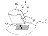
回転子1は、回転子鉄心2と、複数の永久磁石3と、永久磁石3のカバー4とを備えている。図4は永久磁石3およびカバー4の構成を説明する斜視図、図5は永久磁石3がカバー4内に配置された状態を示す側面図、図6、図7、図8は永久磁石3およびカバー4を回転子鉄心2の磁石挿入孔22内に配置する過程を示す模式図である。図6は永久磁石3およびカバー4を回転子鉄心2に挿入する様子を示し、図7は挿入後の様子、図8は挿入後にカバー4を回転子鉄心に固定する様子を示す。また、図7、図8は突起部42Bの構成を分かり易くするため、突起部42B側の方向から見た図としている。また、図9は本実施の形態1の別例の回転子の構成を示す断面図、図10、図11は永久磁石3の断面形状のバリエーションを示す図である。
Embodiment 1 FIG.
1 is a plan view showing a configuration of a rotor 1 of a permanent magnet embedded motor according to Embodiment 1 of the present invention, FIG. 2 is a perspective view of the rotor 1, and FIG. 3 is a cross-sectional view of the rotor 1.
The rotor 1 includes a rotor core 2, a plurality of permanent magnets 3, and a cover 4 for the permanent magnets 3. 4 is a perspective view for explaining the configuration of the permanent magnet 3 and the cover 4, FIG. 5 is a side view showing a state in which the permanent magnet 3 is disposed in the cover 4, and FIGS. FIG. 6 is a schematic diagram showing a process of arranging the cover 4 in the magnet insertion hole 22 of the rotor core 2. 6 shows a state where the permanent magnet 3 and the cover 4 are inserted into the rotor core 2, FIG. 7 shows a state after the insertion, and FIG. 8 shows a state where the cover 4 is fixed to the rotor core after the insertion. 7 and 8 are views seen from the direction of the protrusion 42B in order to facilitate understanding of the structure of the protrusion 42B. 9 is a cross-sectional view showing a configuration of another example of the rotor according to the first embodiment, and FIGS. 10 and 11 are views showing variations in the cross-sectional shape of the permanent magnet 3. FIG.

回転子鉄心2は所定形状に打ち抜かれた電磁鋼板を複数枚積層して構成される。電磁鋼板には板厚が約0.1〜0.5mmのものを使用する。回転子鉄心2には、その中心部に回転軸挿入用の貫通孔21が設けられている。また、回転子鉄心2には、周方向に等間隔で断面略長方形状の4個の磁石挿入孔22が軸方向に貫通して設けられている。   The rotor core 2 is configured by laminating a plurality of electromagnetic steel plates punched into a predetermined shape. A magnetic steel sheet having a thickness of about 0.1 to 0.5 mm is used. The rotor core 2 is provided with a through-hole 21 for inserting a rotating shaft at the center thereof. The rotor core 2 is provided with four magnet insertion holes 22 having a substantially rectangular cross section at equal intervals in the circumferential direction and penetrating in the axial direction.

永久磁石3は断面略長方形状であり、例えばネオジウム系磁石によって形成され、短手方向に磁化されている(図4矢印Aの方向)。永久磁石3はカバー4内に配置された状態で磁石挿入孔22に挿入され、永久磁石3の磁化方向が回転子鉄心2の径方向となるように配置される。また、回転子鉄心2の隣り合う磁石挿入孔22には、互いに極性が反転された永久磁石3が配置される。このように永久磁石3が配置された場合の、回転子1内の磁力線の向きを図3中矢印Bで示す。永久磁石3の径方向内側および外側の2面が磁力線と交わっている。   The permanent magnet 3 has a substantially rectangular cross section, is formed of, for example, a neodymium magnet, and is magnetized in the short direction (the direction of arrow A in FIG. 4). The permanent magnet 3 is inserted into the magnet insertion hole 22 in a state of being disposed in the cover 4, and is disposed so that the magnetization direction of the permanent magnet 3 is the radial direction of the rotor core 2. In addition, permanent magnets 3 whose polarities are reversed are arranged in adjacent magnet insertion holes 22 of the rotor core 2. The direction of the lines of magnetic force in the rotor 1 when the permanent magnet 3 is arranged in this way is indicated by an arrow B in FIG. Two surfaces on the inner side and the outer side of the permanent magnet 3 intersect with the magnetic field lines.

図4、図5に示すように、カバー4は永久磁石3の周方向両側の2面を覆う第1の枠部41と軸方向両側の2面を覆う第2の枠部42とで永久磁石3を取り囲むよう形成される。永久磁石3の磁力線と交わる2面である径方向内側および外側の面は、カバー4に覆われることなくカバー4から露出している。なお、第1の枠部とは、永久磁石3の軸方向の2面以外の4面の内、磁力線と交わらない2面を覆う枠部であり、第2の枠部とは、永久磁石3の軸方向の2面を覆う枠部である。また、径方向、周方向、軸方向は、全て回転子鉄心2に基づく方向である。
本実施の形態1では第1および第2の枠部41、42の径方向の幅を永久磁石3の径方向の幅より小さく設定し、永久磁石3の径方向内側および外側の2面が枠部41、42から突出して露出するように構成されている。
第2の枠部42の一方側(図中上側)の端部には径方向に突出して設けられた抜け止め用の第1の突起部42Aが設けられている。カバー4を回転子鉄心2の磁石挿入孔22に挿入した際には第1の突起部42Aが回転子鉄心2の軸方向一方側(図中上側)の端面と当接して、カバー4が磁石挿入孔22から抜け落ちることを防止する。
第2の枠部42の他方側(図中下側)の端部には軸方向下向きに突出する第2の突起部42Bが設けられている。
As shown in FIGS. 4 and 5, the cover 4 is composed of a first frame portion 41 covering two surfaces on both sides in the circumferential direction of the permanent magnet 3 and a second frame portion 42 covering two surfaces on both sides in the axial direction. 3 is formed to surround 3. The radially inner and outer surfaces, which are the two surfaces that intersect the magnetic lines of force of the permanent magnet 3, are exposed from the cover 4 without being covered by the cover 4. The first frame portion is a frame portion that covers two surfaces of the permanent magnet 3 other than the two surfaces in the axial direction other than the two surfaces that do not intersect the magnetic field lines. The second frame portion is the permanent magnet 3. It is a frame part which covers two surfaces of the axial direction of. The radial direction, the circumferential direction, and the axial direction are all directions based on the rotor core 2.
In the first embodiment, the radial widths of the first and second frame portions 41 and 42 are set to be smaller than the radial width of the permanent magnet 3, and the two surfaces on the radially inner side and the outer side of the permanent magnet 3 are framed. It is comprised so that it may protrude from the parts 41 and 42 and may be exposed.
At one end (upper side in the drawing) of the second frame portion 42, a first protrusion 42A for retaining is provided that protrudes in the radial direction. When the cover 4 is inserted into the magnet insertion hole 22 of the rotor core 2, the first protrusion 42A comes into contact with the end surface on one side (upper side in the figure) of the rotor core 2 so that the cover 4 is a magnet. It is prevented from falling out of the insertion hole 22.
A second protrusion 42B that protrudes downward in the axial direction is provided at the other end (lower side in the drawing) of the second frame part 42.

図4に示すように、永久磁石3はカバー4の開口している側からカバー4内に配置される。そして、図6に示すように、永久磁石3が配置されたカバー4が第2の枠部42側から磁石挿入孔22内へ挿入される。第2の突起部42Bは軸方向に突出して設けられているため、カバー4の磁石挿入孔22への挿入時に、第2の突起部42Bと回転子鉄心2の磁石挿入孔22内壁面とは接触しない。また、カバー4の磁石挿入孔22への挿入時に、第1の枠部41のいずれか一方側の面を磁石挿入孔22の内壁面に沿わせながら挿入することで、永久磁石3の露出面と回転子鉄心2の磁石挿入孔22内壁面との間のクリアランスを一定に保ちながら挿入でき、挿入時における永久磁石3の破損を防ぐ。
図7、図8に示すように、回転子鉄心2の磁石挿入孔22にカバー4を挿入後、第2の突起部42Bにプレス等で荷重をかけ、第2の突起部42Bをその根元部から回転子鉄心2の軸方向他方側の端面方向に折れ曲がるように塑性変形させる。これにより、第2の突起部42Bと回転子鉄心2の端面が圧着され、カバー4を回転子鉄心2の磁石挿入孔22内に固定することができる。なお、ここでは第2の突起部42Bが回転子鉄心2の端面に圧着するよう塑性変形したが、必ずしも圧着する必要はない。第2の突起部42Bと回転子鉄心2が当接することで、永久磁石3およびカバー4が回転子鉄心2内に固定することができ、第2の突起部42Bが回転子鉄心2の端面方向に折れ曲がっていれば、カバー4の回転子鉄心2からの抜け落ちを防止できる。カバー4を固定することでカバー4内に配置された永久磁石3も磁石挿入孔22から抜け落ちることはなく、磁石挿入孔22内に保持される。
なお、カバー4の材質は非磁性体であればよく、金属、非金属のいずれであってもよい。例えば、アルミ合金や非磁性のSUSや樹脂等がある。
As shown in FIG. 4, the permanent magnet 3 is disposed in the cover 4 from the opening side of the cover 4. Then, as shown in FIG. 6, the cover 4 on which the permanent magnet 3 is arranged is inserted into the magnet insertion hole 22 from the second frame portion 42 side. Since the second protrusion 42B is provided so as to protrude in the axial direction, when the cover 4 is inserted into the magnet insertion hole 22, the second protrusion 42B and the inner wall surface of the magnet insertion hole 22 of the rotor core 2 are different from each other. Do not touch. Further, when the cover 4 is inserted into the magnet insertion hole 22, the exposed surface of the permanent magnet 3 is inserted by inserting one of the surfaces of the first frame portion 41 along the inner wall surface of the magnet insertion hole 22. And the inner wall surface of the magnet insertion hole 22 of the rotor core 2 can be inserted while maintaining a constant clearance, and damage to the permanent magnet 3 during insertion can be prevented.
As shown in FIGS. 7 and 8, after inserting the cover 4 into the magnet insertion hole 22 of the rotor core 2, a load is applied to the second projecting portion 42B with a press or the like, and the second projecting portion 42B is moved to its root portion. The plastic core is plastically deformed so as to be bent in the direction of the end face on the other side in the axial direction of the rotor core 2. As a result, the second protrusion 42 </ b> B and the end surface of the rotor core 2 are pressure-bonded, and the cover 4 can be fixed in the magnet insertion hole 22 of the rotor core 2. Here, the second protrusion 42B is plastically deformed so as to be crimped to the end face of the rotor core 2, but it is not always necessary to crimp. The permanent magnet 3 and the cover 4 can be fixed in the rotor core 2 by the contact between the second protrusion 42B and the rotor core 2, and the second protrusion 42B is in the end face direction of the rotor core 2. If the cover 4 is bent, the cover 4 can be prevented from falling off from the rotor core 2. By fixing the cover 4, the permanent magnet 3 disposed in the cover 4 does not fall out of the magnet insertion hole 22 and is held in the magnet insertion hole 22.
In addition, the material of the cover 4 should just be a nonmagnetic material, and may be either a metal or a nonmetal. For example, there are aluminum alloy, nonmagnetic SUS, resin, and the like.

以上のように、本実施の形態1の回転子1は、永久磁石3がカバー4内に配置された状態で磁石挿入孔22に挿入されているため、カバー4の一面を回転子鉄心2の磁石挿入孔22内壁面に沿わせて挿入することができ、永久磁石3の露出面と回転子鉄心2の磁石挿入孔22内壁面との間のクリアランスを一定に保ちながら挿入できる。このため、挿入時における永久磁石3の破損を防ぐ。さらに、永久磁石3の磁力線と交わる2面がカバー4から露出しているため、永久磁石3の露出面と回転子鉄心2との間のクリアランスを最小限に抑えることができ、クリアランスによる磁気抵抗の増加を抑制することができる。また、カバー4は、永久磁石3の磁力線と交わる2面を覆わないような構成であるため、カバー4に渦電流が生じにくく、永久磁石3の周辺に作用する磁束の低下を防ぐことができる。そして、磁気抵抗の増加や渦電流の発生を抑制して磁束の低下を防止することで、モータ特性を向上させることができ、エネルギー消費量を削減することができるという効果も有する。   As described above, the rotor 1 of the first embodiment is inserted into the magnet insertion hole 22 in a state where the permanent magnet 3 is disposed in the cover 4. It can be inserted along the inner wall surface of the magnet insertion hole 22 and can be inserted while maintaining a constant clearance between the exposed surface of the permanent magnet 3 and the inner wall surface of the magnet insertion hole 22 of the rotor core 2. For this reason, the permanent magnet 3 is prevented from being damaged during insertion. Furthermore, since the two surfaces that intersect the magnetic field lines of the permanent magnet 3 are exposed from the cover 4, the clearance between the exposed surface of the permanent magnet 3 and the rotor core 2 can be minimized, and the magnetic resistance due to the clearance is reduced. Can be suppressed. Further, since the cover 4 is configured so as not to cover the two surfaces intersecting with the magnetic lines of force of the permanent magnet 3, eddy current is hardly generated in the cover 4, and a decrease in magnetic flux acting on the periphery of the permanent magnet 3 can be prevented. . And by suppressing the increase in magnetic resistance and generation | occurrence | production of an eddy current and preventing the fall of magnetic flux, a motor characteristic can be improved and it also has the effect that energy consumption can be reduced.

また、カバー4が回転子鉄心2の磁石挿入孔22内に固定されることで、永久磁石3が磁石挿入孔22内に保持される構成であるため、永久磁石3を保持するためのリベットや端板等の保持部材が不要であり、そのような保持部材との接触による永久磁石3の破損という問題が生じない。そして、保持部材が不要であるため、回転子1の軽量化、小型化を図ることができるとともに、簡単な構成で永久磁石3を磁石挿入孔22内に保持することができるため生産工程自体の環境負荷も低減する。
また、第1または第2の突起部42A、42Bを取り除くことで、容易に永久磁石3やカバー4を取り出すことができ、回転子1の分解が容易であるという効果も有する。
さらに、第2の突起部42Bを塑性変形して回転子鉄心2の端面と圧着させることによりカバー4を回転子鉄心2に固定する場合は、カバー4を回転子鉄心2に固定する際に、回転子鉄心2を構成する各電磁鋼板の積層固定を同時に行うことができ、抜きカシメや溶接、接着等の電磁鋼板積層プロセスを削減することができる。
Further, since the permanent magnet 3 is held in the magnet insertion hole 22 by fixing the cover 4 in the magnet insertion hole 22 of the rotor core 2, a rivet for holding the permanent magnet 3 A holding member such as an end plate is unnecessary, and the problem of damage to the permanent magnet 3 due to contact with such a holding member does not occur. Since the holding member is not required, the rotor 1 can be reduced in weight and size, and the permanent magnet 3 can be held in the magnet insertion hole 22 with a simple configuration. Environmental load is also reduced.
Further, by removing the first or second protrusions 42A and 42B, the permanent magnet 3 and the cover 4 can be easily taken out, and the rotor 1 can be easily disassembled.
Furthermore, when fixing the cover 4 to the rotor core 2 by plastically deforming the second protrusion 42B and crimping it to the end face of the rotor core 2, when fixing the cover 4 to the rotor core 2, Lamination and fixing of the respective electromagnetic steel sheets constituting the rotor core 2 can be performed simultaneously, and electromagnetic steel sheet lamination processes such as punching, welding, and adhesion can be reduced.

なお、本実施の形態1では永久磁石3の磁化方向が回転子鉄心2の径方向となるように配置された場合について説明したが、永久磁石3の配置はこれに限られるものではない。例えば、本実施の形態1の別例として、図9に示すように、永久磁石3の磁化方向が回転子鉄心2の周方向となるように配置されてもよい。このように永久磁石3が配置された場合の回転子1内の磁力線の向きは図9中矢印Cで示す通りであり、永久磁石3の磁力線と交わる2面とは周方向両側の2面となる。従って、カバー4の第1の枠部41が永久磁石3の磁力線と交わらない2面である径方向内側と外側の面を覆い、第2の枠部42が軸方向両側の2面を覆い、永久磁石3は磁力線と交わる周方向両側の2面がカバー4から露出するように各枠部41、42により取り囲まれる構成となる。   In the first embodiment, the case where the magnetization direction of the permanent magnet 3 is arranged to be the radial direction of the rotor core 2 has been described. However, the arrangement of the permanent magnet 3 is not limited to this. For example, as another example of the first embodiment, as shown in FIG. 9, the permanent magnet 3 may be arranged so that the magnetization direction is the circumferential direction of the rotor core 2. The direction of the magnetic lines of force in the rotor 1 when the permanent magnet 3 is arranged in this way is as shown by the arrow C in FIG. 9, and the two surfaces intersecting with the magnetic lines of the permanent magnet 3 are two surfaces on both sides in the circumferential direction. Become. Accordingly, the first frame portion 41 of the cover 4 covers the radially inner and outer surfaces which are the two surfaces that do not intersect with the magnetic lines of force of the permanent magnet 3, and the second frame portion 42 covers the two surfaces on both sides in the axial direction. The permanent magnet 3 is configured to be surrounded by the frame portions 41 and 42 so that two surfaces on both sides in the circumferential direction intersecting with the lines of magnetic force are exposed from the cover 4.

また、本実施の形態1では永久磁石3の形状は断面略長方形状であったが、この形状に限られるものではない。
例えば図10に示すように断面略蒲鉾形状の永久磁石5としてもよく、カバー6の第2の枠部620も永久磁石5の形状に合うように形成される。永久磁石5が短手方向(図中矢印D)に磁化されている場合には、磁力線の方向も同じく短手方向となり、永久磁石5の磁力線と交わる2面とは、蒲鉾形状の曲面とその反対側の平面となる。永久磁石5はカバー6の開口している側からカバー6内に配置され、永久磁石5の磁力線と交わる2面が露出するようにカバー6の第1の枠部61と第2の枠部62とに取り囲まれる。
また、例えば図11に示すように断面略瓦形状の永久磁石50としてもよく、カバー60の第2の枠部620も永久磁石50の形状に合うように形成される。永久磁石50が短手方向(図中矢印E)に磁化されている場合には、磁力線の方向も同じく短手方向となり、永久磁石50の磁力線と交わる2面とは、瓦形状の両曲面となる。永久磁石50はカバー60の開口している側からカバー60内に配置され、永久磁石50の磁力線と交わる2面が露出するようにカバー60の第1の枠部610と第2の枠部620とにより取り囲まれる。
Further, in the first embodiment, the shape of the permanent magnet 3 is substantially rectangular in cross section, but is not limited to this shape.
For example, as shown in FIG. 10, the permanent magnet 5 may have a substantially bowl-shaped cross section, and the second frame portion 620 of the cover 6 is also formed to match the shape of the permanent magnet 5. When the permanent magnet 5 is magnetized in the short direction (arrow D in the figure), the direction of the magnetic force line is also the short direction, and the two surfaces intersecting the magnetic force line of the permanent magnet 5 are a saddle-shaped curved surface and its It becomes the opposite plane. The permanent magnet 5 is disposed in the cover 6 from the opening side of the cover 6, and the first frame portion 61 and the second frame portion 62 of the cover 6 are exposed so that two surfaces that intersect the magnetic lines of force of the permanent magnet 5 are exposed. Surrounded by.
For example, as shown in FIG. 11, the permanent magnet 50 may have a substantially tile-shaped cross section, and the second frame portion 620 of the cover 60 is also formed to match the shape of the permanent magnet 50. When the permanent magnet 50 is magnetized in the short direction (arrow E in the figure), the direction of the lines of magnetic force is also the short direction, and the two surfaces intersecting the lines of magnetic force of the permanent magnet 50 are tile-shaped curved surfaces. Become. The permanent magnet 50 is disposed in the cover 60 from the opening side of the cover 60, and the first frame portion 610 and the second frame portion 620 of the cover 60 are exposed so that two surfaces that intersect the magnetic lines of force of the permanent magnet 50 are exposed. Surrounded by and.

実施の形態2.
図12はこの発明の実施の形態2におけるカバーを回転子鉄心に挿入する様子を示す模式図である。本実施の形態2は、上記実施の形態1とカバーの形状と磁石挿入孔の形状が異なっている。それ以外の部分については上記実施の形態1と同様であり、同一符号を付して説明を省略する。
本実施の形態2のカバー7は永久磁石3の周方向両側2面を覆う第1の枠部71と、軸方向両側の2面を覆う第2の枠部72とで永久磁石3を取り囲むように形成される。永久磁石3の磁力線と交わる2面である径方向内側およおび外側の面はカバー7に覆われることなく、カバー7から露出している。カバー7の第1の枠部71には、軸方向に延びる凸部71Aが設けられ、回転子鉄心2の磁石挿入孔22の周方向両側の内壁面には軸方向に延びる凹部22Aが設けられ、凹部22Aに凸部71Aが圧入されることによりカバー7が回転子鉄心2の磁石挿入孔22内に固定される。
Embodiment 2. FIG.
FIG. 12 is a schematic diagram showing a state in which the cover according to Embodiment 2 of the present invention is inserted into the rotor core. The second embodiment differs from the first embodiment in the shape of the cover and the shape of the magnet insertion hole. Other portions are the same as those in the first embodiment, and the same reference numerals are given and the description thereof is omitted.
The cover 7 according to the second embodiment surrounds the permanent magnet 3 with a first frame portion 71 that covers two surfaces on both sides in the circumferential direction of the permanent magnet 3 and a second frame portion 72 that covers two surfaces on both sides in the axial direction. Formed. The radially inner and outer surfaces, which are the two surfaces that intersect the magnetic lines of force of the permanent magnet 3, are exposed from the cover 7 without being covered by the cover 7. The first frame portion 71 of the cover 7 is provided with a convex portion 71A extending in the axial direction, and the inner wall surfaces on both sides in the circumferential direction of the magnet insertion hole 22 of the rotor core 2 are provided with concave portions 22A extending in the axial direction. The cover 7 is fixed in the magnet insertion hole 22 of the rotor core 2 by pressing the protrusion 71A into the recess 22A.

以上のように、本実施の形態2の回転子1は、永久磁石3が配置されたカバー7を磁石挿入孔22に挿入する際に、枠部71の凸部71Aを磁石挿入孔22の凹部22Aに圧入させて挿入するため、挿入中にカバー7の磁石挿入孔22に対する位置が周方向や径方向にずれることがない。このため、永久磁石3の露出面と回転子鉄心2の磁石挿入孔22内壁面との間のクリアランスを一定に保ちながら挿入でき、挿入時における永久磁石3の破損を防ぐ。
また、カバー7の挿入後においても、カバー7は凸部71Aが凹部22Aに圧入されることにより磁石挿入孔22内に強固に固定されるため、回転子1の回転等によってもカバー7の位置が磁石挿入孔22内でずれることがなく、回転子1の回転時の振動発生を抑制することができる。
また、上記実施の形態1と同様に、カバー7が回転子鉄心2の磁石挿入孔22内に固定されることで、永久磁石3が磁石挿入孔22内に保持される構成であるため、永久磁石3を保持するためのリベットや端板等の保持部材が不要であり、そのような保持部材等との接触による永久磁石3の破損という問題が生じない。そして、保持部材が不要であるため、回転子1の軽量化、小型化を図ることができるとともに、簡単な構成で永久磁石3を磁石挿入孔22内に保持することができるため生産工程自体の環境負荷も低減する。
また、上記実施の形態1と同様に、永久磁石3の磁力線と交わる2面がカバー7から露出しているため、永久磁石3の露出面と回転子鉄心2との間のクリアランスを最小限に抑えることができ、クリアランスによる磁気抵抗の増加を抑制することができる。また、カバー7は、永久磁石3の磁力線と交わる2面を覆わないような構成であるため、カバー7に渦電流が生じにくく、永久磁石3の周辺に作用する磁束の低下を防ぐことができる。そして、磁気抵抗の増加や渦電流の発生を抑制して磁束の低下を防止することで、モータ特性を向上させることができ、エネルギー消費量を削減することができるという効果も有する。
As described above, in the rotor 1 of the second embodiment, when the cover 7 on which the permanent magnet 3 is disposed is inserted into the magnet insertion hole 22, the convex portion 71 </ b> A of the frame portion 71 is the concave portion of the magnet insertion hole 22. Since it is press-fitted into 22A and inserted, the position of the cover 7 with respect to the magnet insertion hole 22 does not shift in the circumferential direction or radial direction during insertion. For this reason, the permanent magnet 3 can be inserted while maintaining a constant clearance between the exposed surface of the permanent magnet 3 and the inner wall surface of the magnet insertion hole 22 of the rotor core 2, thereby preventing the permanent magnet 3 from being damaged.
Further, even after the cover 7 is inserted, the cover 7 is firmly fixed in the magnet insertion hole 22 by press-fitting the convex portion 71A into the concave portion 22A. Is not displaced in the magnet insertion hole 22, and the occurrence of vibration during rotation of the rotor 1 can be suppressed.
Similarly to the first embodiment, since the cover 7 is fixed in the magnet insertion hole 22 of the rotor core 2, the permanent magnet 3 is held in the magnet insertion hole 22. A holding member such as a rivet or an end plate for holding the magnet 3 is unnecessary, and there is no problem of damage to the permanent magnet 3 due to contact with such a holding member. Since the holding member is not required, the rotor 1 can be reduced in weight and size, and the permanent magnet 3 can be held in the magnet insertion hole 22 with a simple configuration. Environmental load is also reduced.
Further, as in the first embodiment, since the two surfaces that intersect the magnetic lines of force of the permanent magnet 3 are exposed from the cover 7, the clearance between the exposed surface of the permanent magnet 3 and the rotor core 2 is minimized. It is possible to suppress the increase in magnetic resistance due to the clearance. Further, since the cover 7 is configured so as not to cover the two surfaces intersecting with the magnetic lines of force of the permanent magnet 3, eddy current is hardly generated in the cover 7, and a decrease in magnetic flux acting on the periphery of the permanent magnet 3 can be prevented. . And by suppressing the increase in magnetic resistance and generation | occurrence | production of an eddy current and preventing the fall of magnetic flux, a motor characteristic can be improved and it also has the effect that energy consumption can be reduced.

実施の形態3.
図13はこの発明の実施の形態3における永久磁石とカバーの構成を説明する斜視図である。図に示すように、本実施の形態3では、上記実施の形態1で説明したカバー4の第2の枠部42に、略四角形状の孔部43が設けられている。本実施の形態3では孔部43は軸方向上下両方の枠部42にそれぞれ4個ずつ等間隔で設けられている。それ以外の部分については上記実施の形態1と同様であり、同一符号を付して説明を省略する。
孔部43によりカバー4に発生する渦電流の流れが制限され、カバー4に発生するトータルの渦電流を低下させることができる。
なお、孔部43の形状や個数や配置位置はこれに限られるものではなく、必要に応じて適宜設定すればよい。また、本実施の形態3では上下両面の第2の枠部42に孔部43を設けたが、いずれか一方に設ける構成としてもよく、また、第1の枠部41の2面の内のいずれか一方又は両方に設ける構成としてもよい。また第1および第2の枠部41、42の全ての面に孔部43を設ける構成としてもよい。
Embodiment 3 FIG.
FIG. 13 is a perspective view illustrating the configuration of the permanent magnet and the cover according to Embodiment 3 of the present invention. As shown in the figure, in the third embodiment, a substantially rectangular hole 43 is provided in the second frame portion 42 of the cover 4 described in the first embodiment. In the third embodiment, four holes 43 are provided at equal intervals in both the upper and lower frame parts 42. Other portions are the same as those in the first embodiment, and the same reference numerals are given and the description thereof is omitted.
The flow of eddy current generated in the cover 4 is restricted by the hole 43, and the total eddy current generated in the cover 4 can be reduced.
In addition, the shape, the number, and the arrangement position of the hole 43 are not limited to this, and may be appropriately set as necessary. In the third embodiment, the hole 43 is provided in the second frame 42 on both the upper and lower surfaces. However, the hole 43 may be provided on either one of the two surfaces of the first frame 41. It is good also as a structure provided in any one or both. Moreover, it is good also as a structure which provides the hole part 43 in all the surfaces of the 1st and 2nd frame parts 41 and 42. FIG.

以上のように、本実施の形態3の回転子1は、上記実施の形態1の構成に加えてカバー4の第2の枠部42に孔部43を設けているため、上記実施の形態1の効果に加え、カバー4内に発生する永久磁石3の磁化方向の磁束を打ち消そうとする渦電流の発生をさらに低減することができ、モータ特性をさらに向上させることができる。   As described above, the rotor 1 according to the third embodiment is provided with the hole 43 in the second frame portion 42 of the cover 4 in addition to the configuration of the first embodiment. In addition to the above effect, it is possible to further reduce the generation of eddy currents that try to cancel out the magnetic flux in the magnetization direction of the permanent magnet 3 generated in the cover 4, and to further improve the motor characteristics.

1 回転子、2 回転子鉄心、3 永久磁石、4 カバー、5 永久磁石、
6 カバー、7 カバー、22 磁石挿入孔、22A 凹部、42A 第1の突起部、
42B 第2の突起部、43 孔部、50 永久磁石、60 カバー、71A 凸部。
1 rotor, 2 rotor core, 3 permanent magnet, 4 cover, 5 permanent magnet,
6 cover, 7 cover, 22 magnet insertion hole, 22A recess, 42A first protrusion,
42B 2nd protrusion part, 43 hole part, 50 permanent magnet, 60 cover, 71A convex part.

Claims (7)

複数枚の電磁鋼板を積層してなる回転子鉄心が、軸方向に貫通する複数の磁石挿入孔を有し、上記各磁石挿入孔に、永久磁石および上記永久磁石を磁力線と交わる2面を露出させて取り囲む非磁性体からなるカバーがそれぞれ挿入され、
上記カバーの径方向の幅を上記永久磁石の径方向の幅より小さく設定し、上記永久磁石の径方向内側および径方向外側の2面が上記カバーから突出して露出するように構成された永久磁石埋込型モータの回転子。
A rotor core formed by laminating a plurality of electromagnetic steel sheets has a plurality of magnet insertion holes penetrating in the axial direction, and the two surfaces where the permanent magnets and the permanent magnets intersect with the lines of magnetic force are exposed in the magnet insertion holes. A cover made of a non-magnetic material surrounding each other is inserted,
A permanent magnet configured such that a radial width of the cover is set smaller than a radial width of the permanent magnet, and two surfaces of the permanent magnet on the inner side and the outer side in the radial direction protrude and are exposed from the cover. Embedded motor rotor.
上記カバーの軸方向一方側の端部から突出して設けられ上記回転子鉄心の軸方向一方側の端面と当接する第1の突起部と、上記カバーの軸方向他方側の端部から突出して設けられ上記回転子鉄心の他方側の端面と当接する第2の突起部とを備えたことを特徴とする請求項1に記載の永久磁石埋込型モータの回転子。 A first protrusion that protrudes from one end of the cover in the axial direction and abuts against one end surface of the rotor core in the axial direction, and a protrusion that protrudes from the end of the cover in the other axial direction The rotor of an embedded permanent magnet motor according to claim 1, further comprising a second protrusion that contacts the other end surface of the rotor core. 上記回転子鉄心の上記磁石挿入孔内壁に設けられた軸方向に延びる凹部と、上記カバーに設けられ上記凹部に圧入される軸方向に延びる凸部とを備えたことを特徴とする請求項1又は請求項2に記載の永久磁石埋込型モータの回転子。 The axial direction recessed part provided in the inner wall of the said magnet insertion hole of the said rotor iron core, and the convex part extended in the axial direction provided in the said cover and press-fitted in the said recessed part were provided. Alternatively, a rotor of a permanent magnet embedded motor according to claim 2. 上記カバーの少なくとも1面に孔部を設けたことを特徴とする請求項1から請求項3のいずれか1項に記載の永久磁石埋込型モータの回転子。 The rotor of an embedded permanent magnet motor according to any one of claims 1 to 3, wherein a hole is provided in at least one surface of the cover. 上記各永久磁石は断面略長方形状であることを特徴とする請求項1から請求項4のいずれか1項に記載の永久磁石埋込型モータの回転子。 5. The rotor of an embedded permanent magnet motor according to claim 1, wherein each permanent magnet has a substantially rectangular cross section. 上記各永久磁石は断面略蒲鉾形状であることを特徴とする請求項1から請求項4のいずれか1項に記載の永久磁石埋込型モータの回転子。 5. The rotor of an embedded permanent magnet motor according to claim 1, wherein each of the permanent magnets has a substantially bowl shape in cross section. 上記各永久磁石は断面略瓦形状であることを特徴とする請求項1から請求項4のいずれか1項に記載の永久磁石埋込型モータの回転子。 5. The rotor of a permanent magnet embedded motor according to claim 1, wherein each of the permanent magnets has a substantially roof-shaped cross section.
JP2011128899A 2011-06-09 2011-06-09 Rotor of permanent magnet embedded motor Active JP5653298B2 (en)

Priority Applications (1)

Application Number Priority Date Filing Date Title
JP2011128899A JP5653298B2 (en) 2011-06-09 2011-06-09 Rotor of permanent magnet embedded motor

Applications Claiming Priority (1)

Application Number Priority Date Filing Date Title
JP2011128899A JP5653298B2 (en) 2011-06-09 2011-06-09 Rotor of permanent magnet embedded motor

Publications (3)

Publication Number Publication Date
JP2012257390A JP2012257390A (en) 2012-12-27
JP2012257390A5 JP2012257390A5 (en) 2013-11-28
JP5653298B2 true JP5653298B2 (en) 2015-01-14

Family

ID=47528394

Family Applications (1)

Application Number Title Priority Date Filing Date
JP2011128899A Active JP5653298B2 (en) 2011-06-09 2011-06-09 Rotor of permanent magnet embedded motor

Country Status (1)

Country Link
JP (1) JP5653298B2 (en)

Families Citing this family (3)

* Cited by examiner, † Cited by third party
Publication number Priority date Publication date Assignee Title
JP6126955B2 (en) * 2013-09-13 2017-05-10 株式会社ユタカ技研 Rotor
JP6469964B2 (en) 2014-04-23 2019-02-13 株式会社日立製作所 Permanent magnet rotating electric machine
KR102527782B1 (en) * 2017-12-18 2023-05-02 엘지이노텍 주식회사 Rotor and Motor having the same

Family Cites Families (5)

* Cited by examiner, † Cited by third party
Publication number Priority date Publication date Assignee Title
JP3747107B2 (en) * 1996-12-18 2006-02-22 アイチエレック株式会社 Electric motor
JP2000139063A (en) * 1998-11-02 2000-05-16 Meidensha Corp Permanent magnet type synchronous electric rotating machine
JP2001086671A (en) * 1999-09-13 2001-03-30 Sumitomo Special Metals Co Ltd Magnet for motor, and its fixation method, and motor
JP5396972B2 (en) * 2009-03-31 2014-01-22 アイシン精機株式会社 Motor rotor
EP2249460B1 (en) * 2009-05-05 2012-03-07 Iro Ab Positioning substrate and permanent magnet rotor

Also Published As

Publication number Publication date
JP2012257390A (en) 2012-12-27

Similar Documents

Publication Publication Date Title
JP5976122B2 (en) Permanent magnet embedded motor
JP5258190B2 (en) Laminated iron core structure of stepping motor
JP4709132B2 (en) Rotor of permanent magnet embedded motor, motor for blower and motor for compressor
JP4781197B2 (en) Divided laminated iron core and stator iron core of rotating electric machine using this divided laminated iron core
JP5239200B2 (en) Permanent magnet rotating electric machine
JP5240495B2 (en) motor
EP2696472B1 (en) Rotor yoke and motor comprising the rotor yoke
US11211838B2 (en) IPM rotor
JP2013230047A (en) Rotor for motor, and motor
WO2010116921A1 (en) Magnetic circuit structure
JP2011172441A (en) Motor core and assembling method thereof
JP5353939B2 (en) Rotating electrical machine rotor
JP5653298B2 (en) Rotor of permanent magnet embedded motor
JP2012244649A (en) Rotor and rotary electric machine
JP2012235652A (en) Rotor and rotating electric machine
CN108141078B (en) Rotor of rotating electric machine, rotating electric machine provided with rotor, and method for manufacturing rotor
JP5242720B2 (en) Rotor of permanent magnet embedded motor
JP2011125141A (en) Stator core and method of manufacturing the same
JP4286642B2 (en) Permanent magnet rotor
JP2008072790A (en) Rotor of ipm motor
WO2011132250A1 (en) Rotor for an embedded-magnet synchronous motor
JP3917549B2 (en) Stepping motor
JP2009095200A (en) Rotor of rotary electric machine
JP2012016090A (en) Permanent magnet embedded motor
JP5148019B1 (en) Embedded magnet rotor

Legal Events

Date Code Title Description
A521 Request for written amendment filed

Free format text: JAPANESE INTERMEDIATE CODE: A523

Effective date: 20131010

A621 Written request for application examination

Free format text: JAPANESE INTERMEDIATE CODE: A621

Effective date: 20131010

A977 Report on retrieval

Free format text: JAPANESE INTERMEDIATE CODE: A971007

Effective date: 20140813

A131 Notification of reasons for refusal

Free format text: JAPANESE INTERMEDIATE CODE: A131

Effective date: 20140819

A521 Request for written amendment filed

Free format text: JAPANESE INTERMEDIATE CODE: A523

Effective date: 20140930

TRDD Decision of grant or rejection written
A01 Written decision to grant a patent or to grant a registration (utility model)

Free format text: JAPANESE INTERMEDIATE CODE: A01

Effective date: 20141021

A61 First payment of annual fees (during grant procedure)

Free format text: JAPANESE INTERMEDIATE CODE: A61

Effective date: 20141118

R150 Certificate of patent or registration of utility model

Ref document number: 5653298

Country of ref document: JP

Free format text: JAPANESE INTERMEDIATE CODE: R150

R250 Receipt of annual fees

Free format text: JAPANESE INTERMEDIATE CODE: R250

R250 Receipt of annual fees

Free format text: JAPANESE INTERMEDIATE CODE: R250

R250 Receipt of annual fees

Free format text: JAPANESE INTERMEDIATE CODE: R250

R250 Receipt of annual fees

Free format text: JAPANESE INTERMEDIATE CODE: R250

R250 Receipt of annual fees

Free format text: JAPANESE INTERMEDIATE CODE: R250

R250 Receipt of annual fees

Free format text: JAPANESE INTERMEDIATE CODE: R250

R250 Receipt of annual fees

Free format text: JAPANESE INTERMEDIATE CODE: R250