JP5652359B2 - Electric compressor - Google Patents
Electric compressor Download PDFInfo
- Publication number
- JP5652359B2 JP5652359B2 JP2011198075A JP2011198075A JP5652359B2 JP 5652359 B2 JP5652359 B2 JP 5652359B2 JP 2011198075 A JP2011198075 A JP 2011198075A JP 2011198075 A JP2011198075 A JP 2011198075A JP 5652359 B2 JP5652359 B2 JP 5652359B2
- Authority
- JP
- Japan
- Prior art keywords
- coil
- stator
- electric compressor
- housing
- opening
- Prior art date
- Legal status (The legal status is an assumption and is not a legal conclusion. Google has not performed a legal analysis and makes no representation as to the accuracy of the status listed.)
- Expired - Fee Related
Links
Images


Classifications
-
- F—MECHANICAL ENGINEERING; LIGHTING; HEATING; WEAPONS; BLASTING
- F04—POSITIVE - DISPLACEMENT MACHINES FOR LIQUIDS; PUMPS FOR LIQUIDS OR ELASTIC FLUIDS
- F04C—ROTARY-PISTON, OR OSCILLATING-PISTON, POSITIVE-DISPLACEMENT MACHINES FOR LIQUIDS; ROTARY-PISTON, OR OSCILLATING-PISTON, POSITIVE-DISPLACEMENT PUMPS
- F04C18/00—Rotary-piston pumps specially adapted for elastic fluids
- F04C18/02—Rotary-piston pumps specially adapted for elastic fluids of arcuate-engagement type, i.e. with circular translatory movement of co-operating members, each member having the same number of teeth or tooth-equivalents
- F04C18/0207—Rotary-piston pumps specially adapted for elastic fluids of arcuate-engagement type, i.e. with circular translatory movement of co-operating members, each member having the same number of teeth or tooth-equivalents both members having co-operating elements in spiral form
- F04C18/0215—Rotary-piston pumps specially adapted for elastic fluids of arcuate-engagement type, i.e. with circular translatory movement of co-operating members, each member having the same number of teeth or tooth-equivalents both members having co-operating elements in spiral form where only one member is moving
-
- H—ELECTRICITY
- H02—GENERATION; CONVERSION OR DISTRIBUTION OF ELECTRIC POWER
- H02K—DYNAMO-ELECTRIC MACHINES
- H02K3/00—Details of windings
- H02K3/32—Windings characterised by the shape, form or construction of the insulation
- H02K3/38—Windings characterised by the shape, form or construction of the insulation around winding heads, equalising connectors, or connections thereto
-
- H—ELECTRICITY
- H02—GENERATION; CONVERSION OR DISTRIBUTION OF ELECTRIC POWER
- H02K—DYNAMO-ELECTRIC MACHINES
- H02K11/00—Structural association of dynamo-electric machines with electric components or with devices for shielding, monitoring or protection
- H02K11/30—Structural association with control circuits or drive circuits
- H02K11/33—Drive circuits, e.g. power electronics
-
- H—ELECTRICITY
- H02—GENERATION; CONVERSION OR DISTRIBUTION OF ELECTRIC POWER
- H02K—DYNAMO-ELECTRIC MACHINES
- H02K3/00—Details of windings
- H02K3/04—Windings characterised by the conductor shape, form or construction, e.g. with bar conductors
- H02K3/24—Windings characterised by the conductor shape, form or construction, e.g. with bar conductors with channels or ducts for cooling medium between the conductors
-
- H—ELECTRICITY
- H02—GENERATION; CONVERSION OR DISTRIBUTION OF ELECTRIC POWER
- H02K—DYNAMO-ELECTRIC MACHINES
- H02K3/00—Details of windings
- H02K3/44—Protection against moisture or chemical attack; Windings specially adapted for operation in liquid or gas
-
- H—ELECTRICITY
- H02—GENERATION; CONVERSION OR DISTRIBUTION OF ELECTRIC POWER
- H02K—DYNAMO-ELECTRIC MACHINES
- H02K9/00—Arrangements for cooling or ventilating
- H02K9/19—Arrangements for cooling or ventilating for machines with closed casing and closed-circuit cooling using a liquid cooling medium, e.g. oil
- H02K9/197—Arrangements for cooling or ventilating for machines with closed casing and closed-circuit cooling using a liquid cooling medium, e.g. oil in which the rotor or stator space is fluid-tight, e.g. to provide for different cooling media for rotor and stator
-
- F—MECHANICAL ENGINEERING; LIGHTING; HEATING; WEAPONS; BLASTING
- F04—POSITIVE - DISPLACEMENT MACHINES FOR LIQUIDS; PUMPS FOR LIQUIDS OR ELASTIC FLUIDS
- F04C—ROTARY-PISTON, OR OSCILLATING-PISTON, POSITIVE-DISPLACEMENT MACHINES FOR LIQUIDS; ROTARY-PISTON, OR OSCILLATING-PISTON, POSITIVE-DISPLACEMENT PUMPS
- F04C2240/00—Components
- F04C2240/40—Electric motor
-
- H—ELECTRICITY
- H02—GENERATION; CONVERSION OR DISTRIBUTION OF ELECTRIC POWER
- H02K—DYNAMO-ELECTRIC MACHINES
- H02K7/00—Arrangements for handling mechanical energy structurally associated with dynamo-electric machines, e.g. structural association with mechanical driving motors or auxiliary dynamo-electric machines
- H02K7/14—Structural association with mechanical loads, e.g. with hand-held machine tools or fans
Landscapes
- Engineering & Computer Science (AREA)
- Power Engineering (AREA)
- Mechanical Engineering (AREA)
- General Engineering & Computer Science (AREA)
- Microelectronics & Electronic Packaging (AREA)
- Compressor (AREA)
Description
本願発明は、電動圧縮機、特にステータに巻き付けられたコイルの漏洩電流の抑制と冷却に関する。 The present invention relates to suppression of leakage current and cooling of an electric compressor, particularly a coil wound around a stator.
電動圧縮機はハウジングの内部に圧縮機構及び圧縮機構を駆動する電動モータを収容した構成を有し、車両用空調装置の冷媒回路の一部として車両に搭載されている。一般に車両では、車両に搭載された電気機器及び制御機器等への電動圧縮機の漏洩電流による影響を小さくする必要がある。 The electric compressor has a configuration in which a housing and an electric motor that drives the compression mechanism are housed in a housing, and is mounted on a vehicle as a part of a refrigerant circuit of a vehicle air conditioner. In general, in a vehicle, it is necessary to reduce the influence of leakage current of an electric compressor on electric devices and control devices mounted on the vehicle.
一方、電動圧縮機では、圧縮機の運転が停止されると、冷媒回路中の液化した冷媒や潤滑油の混合体(以下、液冷媒とする)が電動圧縮機の吸入ポートを通してハウジング内部に貯留され易い。電動モータのステータに巻き付けられたコイルは、液冷媒の貯留量の増加に伴い液冷媒中に浸漬される。コイルが液冷媒に浸漬された状態では、液冷媒の誘電率によりコイルとステータ及びステータを固定したハウジングとの間で絶縁性が低下し、ステータやステータを固定したハウジングに流れる漏洩電流が大きくなる。このため、電動圧縮機では、電動圧縮機の停止時における液冷媒の貯留時においても漏洩電流を抑制することが要求される。漏洩電流を抑制する手段としては、一般的に、絶縁性の高い潤滑油(例えばPOE系オイル)と冷媒との組み合わせで使用することにより、漏洩電流を抑制することができる。しかし、絶縁性の高い潤滑油を使用したとしても、電動圧縮機内に絶縁性の低い物質が混入すると漏洩電流を抑制することができない。また、圧縮機の仕様によっては、絶縁性の高くない潤滑油(例えばPAG系オイル)を使用する場合もあり、この場合、漏洩電流を抑制することができない。 On the other hand, in the electric compressor, when the operation of the compressor is stopped, a mixture of liquefied refrigerant and lubricating oil (hereinafter referred to as liquid refrigerant) in the refrigerant circuit is stored in the housing through the suction port of the electric compressor. It is easy to be done. The coil wound around the stator of the electric motor is immersed in the liquid refrigerant as the amount of liquid refrigerant stored increases. In the state where the coil is immersed in the liquid refrigerant, the dielectric constant of the liquid refrigerant reduces the insulation between the coil and the housing to which the stator and the stator are fixed, and the leakage current flowing through the housing to which the stator and the stator are fixed increases. . For this reason, in the electric compressor, it is required to suppress the leakage current even when the liquid refrigerant is stored when the electric compressor is stopped. As a means for suppressing the leakage current, generally, the leakage current can be suppressed by using a combination of a highly insulating lubricating oil (for example, POE oil) and a refrigerant. However, even if lubricating oil with high insulating properties is used, leakage current cannot be suppressed if a material with low insulating properties is mixed in the electric compressor. Further, depending on the specifications of the compressor, a lubricating oil (for example, PAG oil) that is not highly insulating may be used. In this case, the leakage current cannot be suppressed.
例えば、特許文献1には、電動圧縮機における漏洩電流の抑制を目的とした発明が開示されている。特許文献1によると、電動機部(電動モータに相当)に電圧がかかっている状態において、電動機部に付着した冷凍機油(潤滑油に相当)を介して漏洩電流が発生する。即ち、冷凍機油中の冷媒溶解率が大きくなると冷凍機油中に比誘電率の大きい冷媒の溶け込み量が増加するため、大きな漏洩電流が生じる。
For example,
漏洩電流の抑制手段としては、2つの方法が開示されている。1つは、固定子鉄心(ステータに相当)と巻線(コイルに相当)との間の絶縁物を、固定子鉄心のティース部及び/又は巻線のコイルエンド部を包み込むように樹脂モールド成形により形成する方法である。他の1つは、絶縁物を、巻線の全体を包み込むように樹脂モールド成形により形成する方法である。従って、特許文献1は、絶縁物を樹脂モールド成形により形成することにより、ティース部及びコイルエンド部に冷凍機油が付着しても、樹脂モールド成形により絶縁性が向上しているため、漏洩電流を小さくすることができる。
Two methods are disclosed as means for suppressing leakage current. One is resin molding so that the insulator between the stator core (equivalent to the stator) and the winding (corresponding to the coil) wraps around the teeth of the stator core and / or the coil end of the winding. It is the method of forming by. The other is a method of forming an insulator by resin molding so as to wrap the entire winding. Therefore, in
電動圧縮機の運転中、ステータに巻き付けられたコイルは発熱するため、コイル自体が劣化する、あるいは電動圧縮機のハウジング外周に設置された電動モータの電源供給部や制御部が伝熱により熱影響を受ける等の恐れがある。このため、電動モータのステータ及びコイルは、電動圧縮機のハウジング内に収容される構成を利用し、ハウジング内を循環する冷媒によって冷却されている。しかし、特許文献1の発明は、冷媒の溶け込んだ冷凍機油との接触による漏洩電流の発生を抑制するため、コイルエンド部あるいはコイル全体を包み込むように樹脂モールド成形し、絶縁する構成とした。このため、特許文献1に開示された電動圧縮機のコイルは、循環する冷媒から完全に隔絶された構成となり、コイルの発熱による影響を防止できない問題がある。
During operation of the electric compressor, the coil wound around the stator generates heat, so that the coil itself deteriorates, or the power supply section and control section of the electric motor installed on the outer periphery of the housing of the electric compressor are affected by heat transfer. There is a risk of receiving. For this reason, the stator and coil of an electric motor are cooled by the refrigerant | coolant which circulates in the housing using the structure accommodated in the housing of an electric compressor. However, the invention of
本願発明は、ステータに巻き付けられたコイルにおける漏洩電流の抑制と冷却の双方を可能にした電動圧縮機を提供する。 The present invention provides an electric compressor that enables both suppression of leakage current and cooling in a coil wound around a stator.
請求項1は、ハウジングの内部に圧縮機構及び電動モータが収容され、前記電動モータが収容されたハウジングの内部を冷媒が流通し、前記電動モータは回転軸に固定されたロータと前記ハウジングに固定されたステータと該ステータに巻き付けられたコイルとを備え、前記圧縮機構は前記ロータの回転軸に連結して駆動される電動圧縮機において、前記コイルのうち、前記ステータの両端面に突出するコイルエンドを樹脂により被覆した樹脂モールドを有し、前記樹脂モールドの一部に開口部を設け、前記開口部を通して前記コイルエンドの一部を前記ハウジングの内部に露出させ、前記開口部は、前記電動圧縮機の設置状態における重力方向から見て、上側に設けられていることを特徴とする。 According to the first aspect of the present invention, the compression mechanism and the electric motor are accommodated in the housing, the refrigerant flows through the interior of the housing in which the electric motor is accommodated, and the electric motor is fixed to the rotor and the housing fixed to the rotating shaft. In the electric compressor that is driven by being connected to the rotating shaft of the rotor, the coil that protrudes from both ends of the stator among the coils. A resin mold in which an end is coated with a resin, an opening is provided in a part of the resin mold, and a part of the coil end is exposed to the inside of the housing through the opening; It is provided on the upper side when viewed from the direction of gravity in the installed state of the compressor .
請求項1によれば、コイルエンドを樹脂により被覆した樹脂モールドにより、電動圧縮機の停止時にハウジング内に貯留される液冷媒とコイルエンドとの接触によるコイルとステータ及びステータを固定するハウジングとの間の絶縁性の低下を抑制し、漏洩電流を抑制することができる。また、電動圧縮機の運転中にハウジング内を循環する冷媒とコイルエンドとを樹脂モールドの開口部を介して接触させることにより、コイルを冷却することが可能である。また、設置された電動圧縮機のコイルエンドは、下側に存在する部分が停止時にハウジング内に貯留される液冷媒に浸漬され、上側に存在する部分と液冷媒との接触が少ないため、漏洩電流抑制機能と冷却機能とをバランスよく行わせることができる。 According to the first aspect of the present invention, the resin mold in which the coil end is coated with the resin, the coil, the stator, and the housing that fixes the stator by contact between the liquid refrigerant stored in the housing and the coil end when the electric compressor is stopped. It is possible to suppress a decrease in insulation between them and suppress a leakage current. Further, the coil can be cooled by bringing the refrigerant circulating in the housing and the coil end into contact with each other through the opening of the resin mold during operation of the electric compressor. In addition, the coil end of the installed electric compressor leaks because the lower part is immersed in the liquid refrigerant stored in the housing when stopped, and there is little contact between the upper part and the liquid refrigerant. A current suppression function and a cooling function can be performed in a well-balanced manner.
請求項2は、前記電動圧縮機は横置き型であることを特徴とする。請求項2によれば、車載用として多用されている横置き型の電動圧縮機では、ステータの両端部のコイルエンドは停止時にハウジング内に貯留される液冷媒に浸漬されるが、樹脂モールドにより液冷媒との接触を防止され、コイルとステータ及びステータを固定するハウジングとの間の絶縁性の低下による漏洩電流を確実に抑制することができる。 According to a second aspect of the present invention, the electric compressor is a horizontal type. According to the second aspect, in the horizontal type electric compressor widely used for in-vehicle use, the coil ends at both ends of the stator are immersed in the liquid refrigerant stored in the housing when stopped. Contact with the liquid refrigerant is prevented, and leakage current due to a decrease in insulation between the coil and the stator and the housing that fixes the stator can be reliably suppressed.
請求項3は、前記ステータに巻き付けられたコイルは分布巻きされた三相のコイルで構成され、前記開口部は前記上側に位置する少なくとも一相のコイルの一部と対応する位置に設けられていることを特徴とする。請求項3によれば、分布巻きでは、ステータに巻き付けられたコイル束が隣接するコイル束と密着している。このため、コイル束間の熱伝導が高く、一相のコイルの一部を冷却するだけで、樹脂モールドの開口部に対応していない一相の他の部分及び他の相のコイルを十分に冷却することが可能である。 According to a third aspect of the present invention, the coil wound around the stator is composed of a three-phase coil distributedly wound, and the opening is provided at a position corresponding to a part of the at least one-phase coil located on the upper side. It is characterized by being. According to the third aspect , in the distributed winding, the coil bundle wound around the stator is in close contact with the adjacent coil bundle. For this reason, the heat conduction between the coil bundles is high, and by simply cooling a part of the coil of one phase, the other part of the phase not corresponding to the opening of the resin mold and the coil of the other phase are sufficiently It is possible to cool.
請求項4は、前記分布巻きは波巻きであり、前記開口部は前記三相の各コイルの一部と対応する位置に設けられていることを特徴とする。請求項4によれば、波巻きでは三相の各コイルは連続した状態でステータに巻き付けられているため、各相の一部を冷却すれば高い熱伝導により樹脂モールドの開口部を有しない位置のコイルを十分に冷却することができる。 According to a fourth aspect of the present invention, the distributed winding is a wave winding, and the opening is provided at a position corresponding to a part of each of the three-phase coils. According to the fourth aspect , since the three-phase coils are wound around the stator in a continuous state in the wave winding, if a part of each phase is cooled, the position without the resin mold opening due to high heat conduction The coil can be sufficiently cooled.
本願発明は、電動圧縮機において、ステータに巻き付けられたコイルの漏洩電流の抑制と冷却の双方を可能にすることができる。 The invention of the present application can make it possible to both suppress and cool the leakage current of the coil wound around the stator in the electric compressor.
(第1の実施形態)
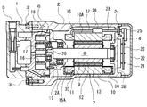
本願発明の第1の実施形態を図1〜図4に基づいて説明する。図1は横置き型にて設置したスクロール式の車載用電動圧縮機(以下、単に電動圧縮機とする)の例を示したもので、電動圧縮機の概要を以下に説明する。なお、横置き型とは、以下に記載される回転軸8が水平となるように電動圧縮機を車両に設置する形態を指す。また、回転軸8が垂直方向となるように設置する形態は縦置き型と呼称する。電動圧縮機は、フロント側のハウジング1とリア側のハウジング2とを複数のボルト3により固定した密閉状のハウジングを有する。ハウジング1、2は共にアルミニウム又はアルミニウム合金等の金属性材料により形成されている。ハウジング2には、吸入ポート4が形成され、また、ハウジング1には、吐出ポート5が形成され、吸入ポート4及び吐出ポート5はそれぞれ図示しない外部冷媒回路と接続されている。従って、ハウジング内は、吸入ポート4から吐出ポート5に向けて冷媒が流通する。
(First embodiment)
A first embodiment of the present invention will be described with reference to FIGS. FIG. 1 shows an example of a scroll type on-vehicle electric compressor (hereinafter simply referred to as an electric compressor) installed in a horizontal type. The outline of the electric compressor will be described below. In addition, a horizontal installation type | mold refers to the form which installs an electric compressor in a vehicle so that the rotating
ハウジング1、2の内部2Aには、スクロール式の圧縮機構6及び圧縮機構6を駆動する電動モータ7が収容されている。電動モータ7は、三相交流モータで構成され、ハウジング2に軸受を介して回転可能に保持された回転軸8と回転軸8に固定されたロータ9とロータ9の外周に配置され、ハウジング2の内壁に固定されたステータ10とを有する。ロータ9は複数の磁性体からなる薄い鋼板を積層した積層鋼板により構成されるロータコア11と複数の永久磁石12とにより構成される。また、ステータ10は円筒状のステータコア13とステータコア13の内周に形成された複数のスロット14に絶縁紙(図示せず)を介して巻き付けられた三相のコイル15を有する。
A scroll
圧縮機構6は、主要素として、ハウジング1、2の内壁に固定された固定スクロール16と、これに対向配置された可動スクロール17とにより構成されている。固定スクロール16と可動スクロール17との間には、冷媒を圧縮するための容積可変の圧縮室18が形成されている。可動スクロール17は、軸受及び偏心ブッシュ19を介して回転軸8の偏心ピン20に連結されることにより、回転軸8の回転に応じて公転運動し、圧縮室18の容積を変化させるよう構成されている。
The
ハウジング2の背面側の端面2Bには、インバータ収容室21を形成するインバータハウジング22が接合され、固定されている。インバータ収容室21内では、ハウジング2の端面2Bに電動モータ7を駆動するためのインバータ23及び気密端子24が取り付けられている。気密端子24は、インバータ収容室21内で、コネクタ25を介してインバータ23と電気的に接続される。また、気密端子24は、端子ピン28及びハウジング2の内部2Aでステータ10の外周部10Aに取り付けられたクラスタブロック26を介してステータ10のコイル15から引き出されているリード線27と電気的に接続される。
An
なお、電動圧縮機は、三相交流電力がインバータ23から気密端子24及びリード線27を介して電動モータ7のコイル15に通電されると、ロータ9が回転され、回転軸8によって圧縮機構6が作動される。
In the electric compressor, when the three-phase AC power is energized from the
電動モータ7のステータ10について、図2及び図3を参照して詳細に説明する。図3に示すように、ステータコア13の内周には、ロータ9の極数(例えば、6極)に対応して、18個のスロット14が等分布に形成され、U相、V相、W相からなる三相のコイル15が分布巻きの一種である波巻きによりステータ10に巻き付けられている。従って、各相のコイル15はステータコア13の両側の端面13A、13Bに突出したコイルエンド15Aを有する。なお、図3では、説明上、三相のコイルエンド15Aが相互に空間を空けて配置された状態で示されているが、実際には、三相のコイルエンド15Aは整形された状態で、相互に密着し、環状に突出した形態である。
The
図3に示すステータコア13の一方の端面13Aに突出した三相のコイルエンド15Aからは、それぞれ2本の引き出し線A1、A2、B1、B2及びC1、C2が引き出されている。各引き出し線A1、B1及びC1は、中性点29用の引き出し線として使用され、3本を結んで、ステータ10の外周部10Aに留められている。また、各引き出し線A2、B2及びC2は、インバータ23及び気密端子24等の駆動回路に接続するためのリード線27として使用され、それぞれリード線27の端部をステータ10の外周部10Aに取り付けられたクラスタブロック26に装着されている。
Two lead wires A1, A2, B1, B2 and C1, C2 are drawn from the three-phase coil ends 15A protruding from one
ステータコア13の端面13A側及び端面13B側に突出するコイルエンド15Aには、図2に示すように、樹脂により被覆された樹脂モールド30が形成されている。樹脂モールド30は端面13A及び端面13Bと密着する状態で形成され、コイルエンド15Aを密閉している。また、樹脂モールド30は、電動圧縮機の設置状態における重力方向から見て、上側に位置するコイルエンド15Aの一部が開放されるように、開口部31を有する。
As shown in FIG. 2, a
樹脂モールド30の開口部31は、図3に示すように、上側に位置するU相、V相及びW相の各コイルエンド15Aの一部と対応する位置に設けられ、各コイルエンド15Aの一部がハウジング2の内部2Aに露出するように構成されている。また、例えば、引き出し線C2のように、樹脂により被覆される箇所では、引き出し線C2が被覆されないように配置して、コイルエンド15Aの樹脂モールド30を形成している。なお、樹脂モールド30に使用する樹脂としては、エポキシ系、フェノール系、不飽和ポリエステル系、ポリイミド系などの樹脂が用いられる。
As shown in FIG. 3, the
以上のように構成された第1の実施形態は以下の作用及び効果を有する。
電動圧縮機の運転が停止されると、ハウジング1、2内に残留する冷媒や潤滑油の混合体である液冷媒32及び吸入ポート4から流入する液冷媒32が、図4に示すように、ハウジング1、2の内部2Aの下側に貯留される。液冷媒32の貯留量は電動圧縮機の停止時間の経過に伴い増量する傾向にある。このため、ステータ10の下側に位置するコイルエンド15Aが液冷媒32中に浸漬される。
The first embodiment configured as described above has the following operations and effects.
When the operation of the electric compressor is stopped, the liquid refrigerant 32 which is a mixture of refrigerant and lubricating oil remaining in the
しかし、コイルエンド15Aは大部分が樹脂モールド30の樹脂により被覆されているため、液冷媒32との接触を遮断され、コイル15とステータ10及びステータ10を固定するハウジング2との間の絶縁性の低下に起因する漏洩電流を確実に抑制することができる。なお、液冷媒32の貯留量はハウジング1、2の内部2Aの上側にまでは達しないため、樹脂モールド30の開口部31を通して内部2Aに露出しているコイルエンド15Aが液冷媒32に浸漬される恐れはない。
However, most of the
一方、電動圧縮機の運転が再開されると、コイル15の発熱が生じるが、上側に位置する樹脂モールド30の開口部31を通して露出するコイルエンド15Aが吸入ポート4から流入し、圧縮機構6側へ流れる冷媒に晒され、冷却される。冷媒に晒されるコイルエンド15Aはコイルエンド15Aの一部であるが、各コイル15は波巻きによりステータ10に巻き付けられているため、樹脂モールド30の樹脂により被覆されているコイルエンド15Aも熱伝導により冷却される。さらに、U相、V相、W相の各コイルエンド15Aの少なくとも一部が冷媒に晒されるようになっており、3相とも冷却される。従って、コイル15は、従来と同様に、十分な冷却効果を得ることができ、コイル15の発熱による影響を確実に防止することができる。
On the other hand, when the operation of the electric compressor is resumed, the
(第2の実施形態)
図5は第2の実施形態を示したもので、第1の実施形態と同一の構成については同一の符号を付し、詳細な説明を省略する。第2の実施形態は、回転軸8の回転中心を通る水平面Xよりも下側に位置するステータコア13及びコイルエンド15Aを全て樹脂モールド33により被覆した構成を有する。従って、水平面Xよりも重力方向の上側には樹脂モールド33の開口部34が形成され、上側に位置する三相のコイル15のコイルエンド15Aは開口部34を通してハウジング1、2の内部2Aに露出される。なお、ステータコア13に樹脂モールド33を形成したステータ10は、ねじ止め等の手段によりハウジング2の内周壁に取り付けることができる。
(Second Embodiment)
FIG. 5 shows the second embodiment. The same components as those in the first embodiment are denoted by the same reference numerals, and detailed description thereof is omitted. The second embodiment has a configuration in which all of the
第2の実施形態は、下側のコイルエンド15Aが電動圧縮機の停止中にハウジング1、2の内部2Aに貯留される液冷媒32に浸漬しても、樹脂モールド33により液冷媒32との接触を防止される。また、電動圧縮機の運転中、樹脂モールド33の開口部34から露出する上側のコイルエンド15Aは、吸入ポート4から圧縮機構6側へ流れる冷媒に十分に晒される。従って、第2の実施形態は第1の実施形態と同等の作用効果を得ることができる。また、第2の実施形態では、下側のステータ10及びコイルエンド15Aの全てが樹脂モールド33の樹脂により被覆されるため、下側に位置するコイル15全体のカバーが可能となり、液冷媒32との接触をより確実に防止することができる。
In the second embodiment, even if the
(参考例1)
図6は参考例1を示したもので、第1の実施形態と同一の構成については同一の符号を付し、詳細な説明を省略する。参考例1は、ステータコア13及びコイルエンド15Aの全体を樹脂モールド35により被覆した構成を有する。また、樹脂モールド35の開口部36は円形状に形成され、ステータコア13の両端面13A、13B側において、回転軸8の回転中心を通る水平面Xよりも上側に位置するコイルエンド15Aと対応する位置に複数設けている。なお、ステータコア13全体に樹脂モールド35を形成したステータ10は、第2の実施形態に示したねじ止めの外、接着剤等の手段によりハウジング2の内周壁に取り付けることができる。
( Reference Example 1 )
FIG. 6 shows Reference Example 1. The same components as those in the first embodiment are denoted by the same reference numerals, and detailed description thereof is omitted. The reference example 1 has a configuration in which the
参考例1は、第2の実施形態と同様に、水平面Xよりも下側に位置するステータコア13及びコイルエンド15Aが樹脂モールド35の樹脂により被覆されているので、電動圧縮機の停止中に貯留される液冷媒32と接触することがない。また、電動圧縮機の運転中は、樹脂モールド35の開口部36を通して内部2Aに露出する上側のコイルエンド15Aが、冷媒に十分に晒される。従って、参考例1は、第1の実施形態及び第2の実施形態と同等の作用効果を得ることができる。
In Reference Example 1 , as in the second embodiment, the
また、参考例1では、開口部36を回転軸8の回転中心を通る水平面Xよりも上側に設けた構成を示したが、上側の開口部36に加えて、図6(b)に仮想線にて示すように、下側にも開口部37を複数設けることが可能である。この場合、下側に設けた開口部37の一部は貯留された液冷媒32に浸漬する可能性があるが、液冷媒32と接するコイルエンド15Aの面積はコイルエンド15A全体に比して小さいため、コイルとステータ及びステータを固定するハウジングとの間の絶縁性の低下を抑制する効果が大きい。逆に、電動圧縮機の運転中におけるコイルエンド15Aと冷媒との接触面積が参考例1よりも大きくなるため、コイル15のより大きな冷却効果を期待することができる。
In the first reference example , the configuration in which the
(参考例2)
図7は参考例2を示したもので、参考例1と同一の構成については同一の符号を付し、詳細な説明を省略する。参考例2は、コイル15の巻線の方法を、コイルエンド15Bが相互に密着しない集中巻きとしている。また、樹脂モールド35の開口部38は集中巻きされた複数相のコイル15のコイルエンド15Bと対応する位置、つまり各スロット14間に対応する位置に設けられており、コイルエンド15Bの数と同数の開口部38が設けられている。従って、漏洩電流を低減するとともに、コイル15を確実に冷却することができる。
( Reference Example 2 )
FIG. 7 shows Reference Example 2. The same components as those in Reference Example 1 are denoted by the same reference numerals, and detailed description thereof is omitted. In Reference Example 2 , the winding method of the
本願発明は、前記した実施形態の構成に限定されるものではなく、本願発明の趣旨の範囲内で種々の変更が可能であり、次のような、他の実施形態で実施することができる。 The present invention is not limited to the configuration of the embodiment described above, and various modifications are possible within the scope of the gist of the present invention, and can be implemented in other embodiments as follows.
(1)第1の実施形態において、樹脂モールド30の開口部31はU相、V相、W相からなる三相のコイル15の内、一相のコイル15のコイルエンド15Aに対応する位置にのみ設ける構成としても良い。この場合、一相のコイルエンド15Aのみが冷媒に晒されて冷却されるが、三相の各コイルエンド15Aは相互に密着し、また波巻きにより巻き付けられているため、熱伝導により三相のコイル15は十分な冷却効果を得ることができる。
(1) In the first embodiment, the
(2)第2の実施形態では、樹脂モールド33の樹脂がステータコア13及びコイルエンド15Aを被覆する構成で示したが、第1の実施形態のように、樹脂モールド33の樹脂がコイルエンド15Aのみを被覆する構成で実施しても良い。
(2) In the second embodiment shaped condition, the
(3)コイル15の巻線の方法は、第1の実施形態に示した波巻きに限らず、分布巻きの一種である同心巻きにしても良い。同心巻きの場合でも、ステータコア13のスロット14に巻きつけられたコイルのコイルエンドは相互に密着しているため、コイル間の熱伝導性が良く、第1、第2の実施形態と同様にコイルの十分な冷却効果を得ることができる。
(3) The winding method of the
(4)インバータ23は、ハウジング2の端面2Bに設ける構成に限らず、ハウジング2の外周面上に設けるように構成しても良い。また、この場合に、クラスタブロック26はステータ10の外周部10Aに取り付けた構成にしても、ステータ10から分離してハウジング2の内部2Aに自由状態で配置する構成にしても良い。
(5)前記実施形態における電動モータ7は、外側に配置したステータ10にロータ9を嵌合するインナーロータの構成を示したが、外側に配置したロータにステータを嵌合するアウターロータの構成であっても、本願発明を実施することができる。
(6)前記実施形態の電動モータ7は、ロータ9の極数を6極、ステータ10のスロット数を18スロットの例を示したが、それ以外の極数、スロット数でもよく、例えばロータの極数を4極、ステータのスロット数を12スロットで構成した電動モータで実施しても良い。
(4) The
(5) The
(6) In the
(7)前記実施形態では、電動モータ7が吸入ポート4側に配置され、吸入冷媒雰囲気下にあるよう構成したが、電動モータ7は吐出ポート5側に配置され、吐出冷媒雰囲気下にあるように構成しても良い。
(8)前記実施形態では、スクロール式電動圧縮機に実施した例を示したが、電動圧縮機はベーン式、スクリュー式等の他の回転式圧縮機やスワッシュ式、ワッブル式等の往復式圧縮機に電動モータを内蔵した電動圧縮機において本願発明を実施することができる。
(9)前記した各実施形態は縦置き方の車載用電動圧縮機においても実施することができ
る。
(7) In the above embodiment, the
(8) In the above-described embodiment, the scroll type electric compressor is shown as an example. However, the electric compressor may be another rotary compressor such as a vane type or a screw type, or a reciprocating type compression such as a swash type or a wobble type. The present invention can be implemented in an electric compressor having a built-in electric motor.
(9) Each of the above-described embodiments can also be implemented in a vertically mounted on-vehicle electric compressor.
(10)前記実施形態では、車載用電動圧縮機において実施した例を示したが、車載用に限定されず、家庭用、工場用等の電動圧縮機においても実施することができる。 (10 ) Although the example implemented in the vehicle-mounted electric compressor was shown in the said embodiment, it is not limited to vehicle-mounted, It can implement also in household and factory electric compressors.
1、2 ハウジング
2A ハウジングの内部
4 吸入ポート
5 吐出ポート
6 圧縮機構
7 電動モータ
9 ロータ
10 ステータ
13 ステータコア
13A、13B 端面
15 コイル
15A、15B コイルエンド
16 固定スクロール
17 可動スクロール
23 インバータ
30、33、35 樹脂モールド
31、34、36、37、38 開口部
32 液冷媒
A1、A2、B1、B2、C1、C2 引き出し線
X 水平面
1, 2
Claims (4)
前記コイルのうち、前記ステータの両端面に突出するコイルエンドを樹脂により被覆した樹脂モールドを有し、前記樹脂モールドの一部に開口部を設け、前記開口部を通して前記コイルエンドの一部を前記ハウジングの内部に露出させ、前記開口部は、前記電動圧縮機の設置状態における重力方向から見て、上側に設けられていることを特徴とする電動圧縮機。 A compression mechanism and an electric motor are accommodated in the housing, and a refrigerant circulates in the housing in which the electric motor is accommodated. The electric motor includes a rotor fixed to a rotating shaft, a stator fixed to the housing, A coil wound around a stator, and the compression mechanism is driven by being connected to a rotating shaft of the rotor.
The coil includes a resin mold in which a coil end protruding from both end faces of the stator is covered with a resin, an opening is provided in a part of the resin mold, and a part of the coil end is passed through the opening. The electric compressor is exposed to the inside of a housing, and the opening is provided on an upper side when viewed from the direction of gravity in the installed state of the electric compressor.
Priority Applications (4)
| Application Number | Priority Date | Filing Date | Title |
|---|---|---|---|
| JP2011198075A JP5652359B2 (en) | 2011-09-12 | 2011-09-12 | Electric compressor |
| CN201210328454.2A CN102996453B (en) | 2011-09-12 | 2012-09-06 | Motor compressor |
| EP12183720.7A EP2568580A3 (en) | 2011-09-12 | 2012-09-10 | Electric compressor |
| US13/608,318 US9212661B2 (en) | 2011-09-12 | 2012-09-10 | Electric compressor with the stator coils coated with resin, the resin having openings exposing the coils to the interior of the housing |
Applications Claiming Priority (1)
| Application Number | Priority Date | Filing Date | Title |
|---|---|---|---|
| JP2011198075A JP5652359B2 (en) | 2011-09-12 | 2011-09-12 | Electric compressor |
Related Child Applications (1)
| Application Number | Title | Priority Date | Filing Date |
|---|---|---|---|
| JP2014198335A Division JP5929991B2 (en) | 2014-09-29 | 2014-09-29 | Electric compressor |
Publications (2)
| Publication Number | Publication Date |
|---|---|
| JP2013060822A JP2013060822A (en) | 2013-04-04 |
| JP5652359B2 true JP5652359B2 (en) | 2015-01-14 |
Family
ID=46829668
Family Applications (1)
| Application Number | Title | Priority Date | Filing Date |
|---|---|---|---|
| JP2011198075A Expired - Fee Related JP5652359B2 (en) | 2011-09-12 | 2011-09-12 | Electric compressor |
Country Status (4)
| Country | Link |
|---|---|
| US (1) | US9212661B2 (en) |
| EP (1) | EP2568580A3 (en) |
| JP (1) | JP5652359B2 (en) |
| CN (1) | CN102996453B (en) |
Families Citing this family (15)
| Publication number | Priority date | Publication date | Assignee | Title |
|---|---|---|---|---|
| CN104603460B (en) * | 2012-10-30 | 2016-08-31 | 松下知识产权经营株式会社 | Motor compressor |
| CN104737428B (en) * | 2013-03-15 | 2016-07-27 | 松下知识产权经营株式会社 | Device for detecting rotational position |
| DE102013214386A1 (en) * | 2013-07-23 | 2015-01-29 | Zf Friedrichshafen Ag | Electric machine |
| JP6194877B2 (en) * | 2014-12-19 | 2017-09-13 | トヨタ自動車株式会社 | Rotating electric machine |
| JP6560033B2 (en) * | 2015-06-25 | 2019-08-14 | 株式会社日立製作所 | Rotating electric machine and rotating electric machine cooling system |
| EP3176437B1 (en) * | 2015-08-25 | 2019-01-30 | Panasonic Corporation | Closed compressor and refrigeration device |
| CN110168877B (en) * | 2016-12-23 | 2021-08-10 | 维斯塔斯风力系统集团公司 | Electrical isolation mounting of motor stator |
| DE102017208564A1 (en) * | 2017-05-19 | 2018-11-22 | Mahle International Gmbh | Electric machine, in particular for a vehicle |
| JP2020051328A (en) * | 2018-09-27 | 2020-04-02 | サンデン・オートモーティブコンポーネント株式会社 | Motor compressor |
| JP7313159B2 (en) * | 2019-02-27 | 2023-07-24 | フォスター電機株式会社 | vibration actuator |
| DE102020121432B4 (en) | 2020-08-14 | 2022-06-09 | Dr. Ing. H.C. F. Porsche Aktiengesellschaft | Drive train with an electric machine and an inverter, motor vehicle |
| JP2022147523A (en) * | 2021-03-23 | 2022-10-06 | サンデン・オートモーティブコンポーネント株式会社 | Motor compressor |
| JP2022162797A (en) * | 2021-04-13 | 2022-10-25 | 三菱重工サーマルシステムズ株式会社 | electric compressor |
| DE102022107812A1 (en) | 2022-04-01 | 2023-10-05 | Hanon Systems | Electric refrigerant compressor with suction gas cooling |
| DE102022209762A1 (en) * | 2022-09-16 | 2024-03-21 | Rolls-Royce Deutschland Ltd & Co Kg | Electric machine with open coil winding for direct cooling |
Family Cites Families (16)
| Publication number | Priority date | Publication date | Assignee | Title |
|---|---|---|---|---|
| JPH01130076A (en) | 1987-11-12 | 1989-05-23 | Matsushita Electric Ind Co Ltd | Close-type refrigerating compressor |
| DE3825035B4 (en) * | 1988-07-09 | 2006-11-23 | Flux-Geräte GmbH | Brushless, electrically commutated motor for a drum or a container pump to Betieb on an AC voltage network |
| JPH10271738A (en) * | 1997-03-21 | 1998-10-09 | Shibaura Eng Works Co Ltd | Motor for pump |
| JP4176231B2 (en) * | 1999-03-23 | 2008-11-05 | 東芝キヤリア株式会社 | Hermetic electric compressor |
| JP4073622B2 (en) | 2000-12-18 | 2008-04-09 | サンデン株式会社 | Electric compressor |
| JP2002227767A (en) * | 2001-01-30 | 2002-08-14 | Mitsubishi Electric Corp | Hermetic compressor |
| JP2003184775A (en) * | 2001-09-10 | 2003-07-03 | Hitachi Ltd | Scroll compressor and refrigeration unit for ammonia series refrigerant |
| JP2004183499A (en) * | 2002-11-29 | 2004-07-02 | Denso Corp | Electric compressor |
| JP4586542B2 (en) * | 2005-01-17 | 2010-11-24 | トヨタ自動車株式会社 | Rotating electric machine |
| JP4287418B2 (en) * | 2005-09-02 | 2009-07-01 | 本田技研工業株式会社 | Motor connection structure |
| JP4293207B2 (en) * | 2006-07-21 | 2009-07-08 | 株式会社日立製作所 | Electric pump |
| JP2008042956A (en) | 2006-08-01 | 2008-02-21 | Denso Corp | Electric compressor |
| JP2008184995A (en) | 2007-01-31 | 2008-08-14 | Denso Corp | Electric compressor |
| BRPI0706119A2 (en) * | 2007-10-02 | 2009-06-02 | Whirlpool Sa | process of electrical insulation of a coil of an electrical device and arrangement of electrical insulation of a coil of an electrical device |
| JP4985590B2 (en) | 2008-09-02 | 2012-07-25 | 株式会社豊田自動織機 | Electric compressor |
| JP5446531B2 (en) | 2009-07-14 | 2014-03-19 | 株式会社豊田自動織機 | Interphase insulation structure in rotating electrical machine and method of assembling interphase insulating sheet in rotating electrical machine |
-
2011
- 2011-09-12 JP JP2011198075A patent/JP5652359B2/en not_active Expired - Fee Related
-
2012
- 2012-09-06 CN CN201210328454.2A patent/CN102996453B/en not_active Expired - Fee Related
- 2012-09-10 US US13/608,318 patent/US9212661B2/en not_active Expired - Fee Related
- 2012-09-10 EP EP12183720.7A patent/EP2568580A3/en not_active Withdrawn
Also Published As
| Publication number | Publication date |
|---|---|
| EP2568580A2 (en) | 2013-03-13 |
| JP2013060822A (en) | 2013-04-04 |
| CN102996453B (en) | 2015-11-18 |
| EP2568580A3 (en) | 2017-03-08 |
| CN102996453A (en) | 2013-03-27 |
| US9212661B2 (en) | 2015-12-15 |
| US20130064697A1 (en) | 2013-03-14 |
Similar Documents
| Publication | Publication Date | Title |
|---|---|---|
| JP5652359B2 (en) | Electric compressor | |
| JP5811422B2 (en) | Rotating electric machine | |
| JP5804450B2 (en) | Rotating electric machine | |
| US9337693B2 (en) | Rotary electric machine with segment type of stator winding | |
| WO2015159658A1 (en) | Permanent-magnet dynamo-electric machine and compressor using same | |
| US9136739B2 (en) | Rotary electric machine | |
| US10038353B2 (en) | Dual-rotor electric rotating machine | |
| US9234527B2 (en) | Motor driven compressor | |
| WO2014103482A1 (en) | Inverter-integrated electrical compressor | |
| JP5929991B2 (en) | Electric compressor | |
| JP2013141410A (en) | Stator of rotary electric machine and rotary electric machine using the same | |
| JP6818602B2 (en) | Rotating electric machine with control device | |
| JP5634202B2 (en) | Electric compressor and control device thereof | |
| JP2018033197A (en) | Inverter-integrated type rotary electric machine | |
| JP6739529B2 (en) | Stator of rotating electric machine, rotating electric machine and compressor | |
| JP2012005204A (en) | Motor cooling structure | |
| EP2191991A1 (en) | Electric compressor integrated with inverter | |
| JP6518720B2 (en) | Permanent magnet type rotary electric machine and compressor using the same | |
| US20210159750A1 (en) | Electric compressor | |
| JP5645605B2 (en) | Electric compressor and control device thereof | |
| WO2018230267A1 (en) | Inverter-integrated electric compressor | |
| JP2018168831A (en) | Electric compressor | |
| JP2015116086A (en) | Dynamo-electric machine, and on-vehicle motor compressor | |
| WO2022113346A1 (en) | Stator, motor, compressor, and refrigeration cycle device | |
| WO2023132201A1 (en) | Rotating machine |
Legal Events
| Date | Code | Title | Description |
|---|---|---|---|
| A621 | Written request for application examination |
Free format text: JAPANESE INTERMEDIATE CODE: A621 Effective date: 20131001 |
|
| A977 | Report on retrieval |
Free format text: JAPANESE INTERMEDIATE CODE: A971007 Effective date: 20140722 |
|
| A131 | Notification of reasons for refusal |
Free format text: JAPANESE INTERMEDIATE CODE: A131 Effective date: 20140729 |
|
| A521 | Request for written amendment filed |
Free format text: JAPANESE INTERMEDIATE CODE: A523 Effective date: 20140929 |
|
| TRDD | Decision of grant or rejection written | ||
| A01 | Written decision to grant a patent or to grant a registration (utility model) |
Free format text: JAPANESE INTERMEDIATE CODE: A01 Effective date: 20141021 |
|
| A61 | First payment of annual fees (during grant procedure) |
Free format text: JAPANESE INTERMEDIATE CODE: A61 Effective date: 20141103 |
|
| R151 | Written notification of patent or utility model registration |
Ref document number: 5652359 Country of ref document: JP Free format text: JAPANESE INTERMEDIATE CODE: R151 |
|
| LAPS | Cancellation because of no payment of annual fees |