DE3825035B4 - Brushless, electrically commutated motor for a drum or a container pump to Betieb on an AC voltage network - Google Patents
Brushless, electrically commutated motor for a drum or a container pump to Betieb on an AC voltage network Download PDFInfo
- Publication number
- DE3825035B4 DE3825035B4 DE3825035A DE3825035A DE3825035B4 DE 3825035 B4 DE3825035 B4 DE 3825035B4 DE 3825035 A DE3825035 A DE 3825035A DE 3825035 A DE3825035 A DE 3825035A DE 3825035 B4 DE3825035 B4 DE 3825035B4
- Authority
- DE
- Germany
- Prior art keywords
- housing
- motor
- motor according
- rotor
- engine
- Prior art date
- Legal status (The legal status is an assumption and is not a legal conclusion. Google has not performed a legal analysis and makes no representation as to the accuracy of the status listed.)
- Expired - Lifetime
Links
- 230000007246 mechanism Effects 0.000 claims abstract description 4
- 238000001816 cooling Methods 0.000 claims description 5
- 238000001514 detection method Methods 0.000 claims description 5
- 238000010438 heat treatment Methods 0.000 claims description 2
- 238000005253 cladding Methods 0.000 claims 1
- 230000008878 coupling Effects 0.000 description 4
- 238000010168 coupling process Methods 0.000 description 4
- 238000005859 coupling reaction Methods 0.000 description 4
- 239000002360 explosive Substances 0.000 description 4
- 239000002184 metal Substances 0.000 description 4
- OKTJSMMVPCPJKN-UHFFFAOYSA-N Carbon Chemical compound [C] OKTJSMMVPCPJKN-UHFFFAOYSA-N 0.000 description 3
- 229910052799 carbon Inorganic materials 0.000 description 3
- 239000002817 coal dust Substances 0.000 description 3
- 238000004880 explosion Methods 0.000 description 3
- 239000002245 particle Substances 0.000 description 3
- 238000004804 winding Methods 0.000 description 3
- 230000008901 benefit Effects 0.000 description 2
- 239000003610 charcoal Substances 0.000 description 2
- 239000003245 coal Substances 0.000 description 2
- 230000001419 dependent effect Effects 0.000 description 2
- 230000017525 heat dissipation Effects 0.000 description 2
- 238000009413 insulation Methods 0.000 description 2
- 238000012544 monitoring process Methods 0.000 description 2
- 238000005096 rolling process Methods 0.000 description 2
- 238000009825 accumulation Methods 0.000 description 1
- 230000033228 biological regulation Effects 0.000 description 1
- 230000008859 change Effects 0.000 description 1
- 230000002542 deteriorative effect Effects 0.000 description 1
- 238000010292 electrical insulation Methods 0.000 description 1
- 230000005611 electricity Effects 0.000 description 1
- 238000005538 encapsulation Methods 0.000 description 1
- 239000012530 fluid Substances 0.000 description 1
- 238000012423 maintenance Methods 0.000 description 1
- 239000000463 material Substances 0.000 description 1
- 238000000034 method Methods 0.000 description 1
- 230000005405 multipole Effects 0.000 description 1
- 230000035515 penetration Effects 0.000 description 1
- 230000002093 peripheral effect Effects 0.000 description 1
- 230000008569 process Effects 0.000 description 1
- 230000001360 synchronised effect Effects 0.000 description 1
Classifications
-
- F—MECHANICAL ENGINEERING; LIGHTING; HEATING; WEAPONS; BLASTING
- F04—POSITIVE - DISPLACEMENT MACHINES FOR LIQUIDS; PUMPS FOR LIQUIDS OR ELASTIC FLUIDS
- F04D—NON-POSITIVE-DISPLACEMENT PUMPS
- F04D13/00—Pumping installations or systems
- F04D13/02—Units comprising pumps and their driving means
- F04D13/06—Units comprising pumps and their driving means the pump being electrically driven
-
- H—ELECTRICITY
- H02—GENERATION; CONVERSION OR DISTRIBUTION OF ELECTRIC POWER
- H02K—DYNAMO-ELECTRIC MACHINES
- H02K11/00—Structural association of dynamo-electric machines with electric components or with devices for shielding, monitoring or protection
- H02K11/20—Structural association of dynamo-electric machines with electric components or with devices for shielding, monitoring or protection for measuring, monitoring, testing, protecting or switching
- H02K11/28—Manual switches
-
- H—ELECTRICITY
- H02—GENERATION; CONVERSION OR DISTRIBUTION OF ELECTRIC POWER
- H02K—DYNAMO-ELECTRIC MACHINES
- H02K11/00—Structural association of dynamo-electric machines with electric components or with devices for shielding, monitoring or protection
- H02K11/30—Structural association with control circuits or drive circuits
- H02K11/33—Drive circuits, e.g. power electronics
-
- H—ELECTRICITY
- H02—GENERATION; CONVERSION OR DISTRIBUTION OF ELECTRIC POWER
- H02K—DYNAMO-ELECTRIC MACHINES
- H02K29/00—Motors or generators having non-mechanical commutating devices, e.g. discharge tubes or semiconductor devices
- H02K29/06—Motors or generators having non-mechanical commutating devices, e.g. discharge tubes or semiconductor devices with position sensing devices
- H02K29/08—Motors or generators having non-mechanical commutating devices, e.g. discharge tubes or semiconductor devices with position sensing devices using magnetic effect devices, e.g. Hall-plates, magneto-resistors
-
- H—ELECTRICITY
- H02—GENERATION; CONVERSION OR DISTRIBUTION OF ELECTRIC POWER
- H02K—DYNAMO-ELECTRIC MACHINES
- H02K5/00—Casings; Enclosures; Supports
- H02K5/04—Casings or enclosures characterised by the shape, form or construction thereof
-
- H—ELECTRICITY
- H02—GENERATION; CONVERSION OR DISTRIBUTION OF ELECTRIC POWER
- H02K—DYNAMO-ELECTRIC MACHINES
- H02K5/00—Casings; Enclosures; Supports
- H02K5/04—Casings or enclosures characterised by the shape, form or construction thereof
- H02K5/08—Insulating casings
-
- H—ELECTRICITY
- H02—GENERATION; CONVERSION OR DISTRIBUTION OF ELECTRIC POWER
- H02K—DYNAMO-ELECTRIC MACHINES
- H02K5/00—Casings; Enclosures; Supports
- H02K5/04—Casings or enclosures characterised by the shape, form or construction thereof
- H02K5/12—Casings or enclosures characterised by the shape, form or construction thereof specially adapted for operating in liquid or gas
- H02K5/136—Casings or enclosures characterised by the shape, form or construction thereof specially adapted for operating in liquid or gas explosion-proof
-
- H—ELECTRICITY
- H02—GENERATION; CONVERSION OR DISTRIBUTION OF ELECTRIC POWER
- H02K—DYNAMO-ELECTRIC MACHINES
- H02K5/00—Casings; Enclosures; Supports
- H02K5/04—Casings or enclosures characterised by the shape, form or construction thereof
- H02K5/22—Auxiliary parts of casings not covered by groups H02K5/06-H02K5/20, e.g. shaped to form connection boxes or terminal boxes
- H02K5/225—Terminal boxes or connection arrangements
-
- H—ELECTRICITY
- H02—GENERATION; CONVERSION OR DISTRIBUTION OF ELECTRIC POWER
- H02K—DYNAMO-ELECTRIC MACHINES
- H02K9/00—Arrangements for cooling or ventilating
- H02K9/02—Arrangements for cooling or ventilating by ambient air flowing through the machine
- H02K9/04—Arrangements for cooling or ventilating by ambient air flowing through the machine having means for generating a flow of cooling medium
- H02K9/06—Arrangements for cooling or ventilating by ambient air flowing through the machine having means for generating a flow of cooling medium with fans or impellers driven by the machine shaft
Landscapes
- Engineering & Computer Science (AREA)
- Power Engineering (AREA)
- Microelectronics & Electronic Packaging (AREA)
- Mechanical Engineering (AREA)
- General Engineering & Computer Science (AREA)
- Motor Or Generator Frames (AREA)
- Connection Of Motors, Electrical Generators, Mechanical Devices, And The Like (AREA)
- Structures Of Non-Positive Displacement Pumps (AREA)
Abstract
Bürstenloser,
elektronisch kommutierter Motor für eine Faß- oder eine Behälterpumpe
zum Betrieb an einem Wechselspannungsnetz,
– mit einem Gehäuse (1),
in dem eine Rotorwelle (9) drehbar gelagert ist, die einen Rotor
(17) trägt,
dem ein gehäusefester
Stator (26) zugeordnet ist,
– mit einer Netzanschlußleitung,
die an eine Schaltungseinrichtung (20) angeschlossen ist, die eine
im Gehäuse
(1) des Motors untergebrachte Leistungselektronik (20) ist, die für die Drehbewegung
des Rotors (17) Spulen des Stators (26) mit Strom versorgt, über die
Netzanschlußleitung
direkt an das Wechselspannungsnetz anschließbar ist und die Drehzahl des
Motors stromabhängig
steuert, und
– mit
einem im Gehäuse
(1) angeordneten Motorschutzschalter (27), der indirekt über einen
Betätigungsmechanismus
(48) von außen
betätigbar
ist.Brushless, electronically commutated motor for a drum or a container pump for operation on an AC voltage network,
- With a housing (1) in which a rotor shaft (9) is rotatably mounted, which carries a rotor (17), which is associated with a housing fixed stator (26),
- with a mains lead connected to a circuit means (20) which is a power electronics unit (20) housed in the housing (1) of the motor for energizing coils of the stator (26) for the rotational movement of the rotor (17); can be connected directly to the AC mains via the mains connection line and controls the speed of the motor depending on the current, and
- With a housing (1) arranged motor protection switch (27) which is indirectly actuated via an actuating mechanism (48) from the outside.
Description
Die Erfindung betrifft einen bürstenlosen, elektrisch kommutierten Motor für eine Faß- oder eine Behälterpumpe zum Betrieb an einem Wechselspannungsnetz.The The invention relates to a brushless, electric commutated motor for a barrel or a container pump for operation on an AC voltage network.
Es sind Pumpenmotoren als Kollektormotoren bekannt. Bei derartigen Motoren tritt das Problem auf, daß sich im Motorgehäuse mit der Zeit Kohlenstaubablagerungen bilden. Dies ist insbesondere bei druckgekapselten geschlossenen Gehäusen der Fall. Es kann dann zu unerwünschten Kriechströmen kommen. Sie können zu einer Funkenbildung führen. Wird mit einer solchen Pumpe in explosionsgefährdeten Räumen gearbeitet, dann kann es infolge dieser Funkenbildung zu Explosionen kommen. Allerdings entsteht die Funkenbildung nur dann, wenn diese Kollektormotoren nicht ordnungsgemäß gehandhabt werden. So ist vorgeschrieben, daß an den Pumpenmotoren ein Potentialausgleich vorgenommen wird, um solche schädlichen Funkenbildungen zu verhindern. Häufig wird aber ein solcher Potentialausgleich aus Bequemlichkeitsgründen oder Unwissenheit nicht vorgenommen.It Pump motors are known as collector motors. In such Engines the problem occurs that in the motor housing with make coal dust deposits over time. This is especially true with pressure-sealed closed housings the case. It can then become undesirable Creepage currents are coming. You can lead to a sparking. Becomes worked with such a pump in potentially explosive atmospheres, then can there will be explosions as a result of this sparking. Indeed The sparking occurs only when these collector motors not handled properly become. So it is prescribed that at the pump motors Potential equalization is made to such harmful To prevent sparking. Often but is such equipotential bonding for reasons of convenience or Ignorance not made.
Aus diesem Grunde sind Pumpenmotoren entwickelt worden, bei denen auch bei nicht ordnungsgemäßer Handhabung die Gefahr von Explosionen weitgehend ausgeschaltet ist. Hierbei ist der explosionsgeschützte druckgekapselte Pumpenmotor doppelt isoliert, bei dem das metallische Motorgehäuse von einer Kunststoffisolierung umgeben ist. Es können jedoch auch bei einem solchen Motor noch Kriechströme infolge der Kohlenstaubablagerungen im Gehäuseinnenraum auftreten. Die Kollektormotoren haben weiterhin den Nachteil, daß die Bürsten und die Kollektoren verschleißen. Darum ist die Standzeit solcher Motoren verhältnismäßig gering und liegt in der Größenordnung von etwa 500 Betriebsstunden.Out For this reason, pump motors have been developed in which as well if not handled properly the danger of explosions is largely eliminated. in this connection is the explosion-proof pressure-sealed pump motor double insulated, in which the metallic motor housing surrounded by a plastic insulation. However, it can also be at a such engine still leakage currents occur as a result of the coal dust deposits in the housing interior. The Collector motors also have the disadvantage that the brushes and the collectors wear out. Therefore, the life of such engines is relatively low and is in the Magnitude of about 500 operating hours.
Aus
der
Es
ist auch bekannt (
Aus
der
Schließlich ist aus der US-PS 4 511 312 ein bürstenloser Motor bekannt, mit dem die Motorwelle angetrieben wird und der ein Dreiphasen-Drehstrommotor ist, bei dem die Drehzahl der Pumpenwelle durch Frequenzänderung geändert wird. Die Schaltungseinrichtung ist im Pumpengehäuse untergebracht.Finally is from US-PS 4,511,312 a brushless Motor known, with which the motor shaft is driven and the one Three-phase three-phase motor is where the speed of the pump shaft through frequency change changed becomes. The circuit device is housed in the pump housing.
Der Erfindung liegt die Aufgabe zugrunde, den Motor so auszubilden, daß mit ihm auch bei nicht ordnungsgemäßer Handhabung einfach und gefahrenfrei gearbeitet werden kann.Of the Invention is based on the object of designing the motor in such a way that that with him even with improper handling can be worked easily and without danger.
Diese Aufgabe wird beim Motor erfindungsgemäß mit den Merkmalen des Anspruches 1 gelöst.These Task is the engine according to the invention with the features of the claim 1 solved.
Der erfindungsgemäße Motor ist ein bürstenloser, elektrisch kommutierter Gleichstrommotor. Bei einem solchen Motor tritt keine innere Kohlenstaubverschmutzung auf, so daß die bei bekannten Kollektormotoren hiermit verbundenen Kriechströme mit Sicherheit nicht auftreten können. Darum kann mit diesem Motor, wenn er ein druckgekapseltes Gehäuse aufweist, gefahrlos in explosionsgefährdeten Räumen gearbeitet werden. Die gesamte Schaltungselektronik ist im Motorgehäuse untergebracht. Darum sind für den Motor Schaltschränke, Schaltkästen und dergleichen nicht erforderlich. Außerdem kann dadurch die Netzspannung innerhalb des Motorgehäuses verarbeitet werden. Da beim erfindungsgemäßen Motor keine Kohleabriebteilchen auftreten, bleibt das elektrische Isolationssystem dieses Motors auch nach sehr langen Betriebszeiten praktisch unverändert. Die Sicherheit gegen Unfälle ist dadurch während der gesamten Lebensdauer dieses Motors gewährleistet. Da der Gehäuseinnenraum frei von Kohleabriebteilchen bleibt, können die für die Schutzklasse II nach DIN/VDE erforderlichen Maßnahmen einfach durchgeführt werden. Die Schaltungselektronik kann beispielsweise für einen Spannungsbereich von 12 V bis 240 V ausgelegt werden, so daß dann dieser Motor für die Schutzklassen I, II und III ohne weiteres eingesetzt werden kann. Mit dem Motorschutzschalter wird verhindert, daß ein selbständiger Wiederanlauf bei ausgefallenem Netz zuverlässig verhindert wird. Da der Motorschutzschalter indirekt über den Betätigungsmechanismus von außen betätigt wird, kann der Motorschutzschalter im Motorgehäuse geschützt untergebracht werden. Der Motorschutzschalter wird auch nicht durch inneren Kohlenstaub verschmutzt, da der Motor elektronisch kommutiert ist.The motor according to the invention is a brushless, electrically commutated DC motor. In such a motor, no internal pulverized coal pollution occurs, so that the creepage currents associated with known collector motors can not occur with certainty. Therefore, with this motor, if it has a pressure-encapsulated housing, it can be safely used in potentially explosive atmospheres. The entire electronic circuit is housed in the motor housing. Therefore, cabinets, control boxes and the like are not required for the engine. In addition, this can be used to process the mains voltage within the motor housing. Since the engine according to the invention no Kohleabriebteilchen occur, the electrical insulation system of this engine remains virtually unchanged even after very long periods of operation. The safety against accidents is guaranteed throughout the life of this engine. Since the interior of the housing remains free of carbon particles, the measures required for protection class II according to DIN / VDE can be easily carried out. The circuit electronics can be designed for example for a voltage range of 12 V to 240 V, so that then this motor for the protection classes I, II and III readily can be used. The motor-protective circuit-breaker prevents an independent restart from being reliably prevented in the event of a failed network. Since the motor protection switch is actuated indirectly via the actuating mechanism from the outside, the motor protection switch can be housed protected in the motor housing. The motor protection switch is also not polluted by internal pulverized coal, since the motor is electronically commutated.
Weitere Merkmale der Erfindung ergeben sich aus den weiteren Ansprüchen, der Beschreibung und der Zeichnung.Further Features of the invention will become apparent from the other claims, the Description and the drawing.
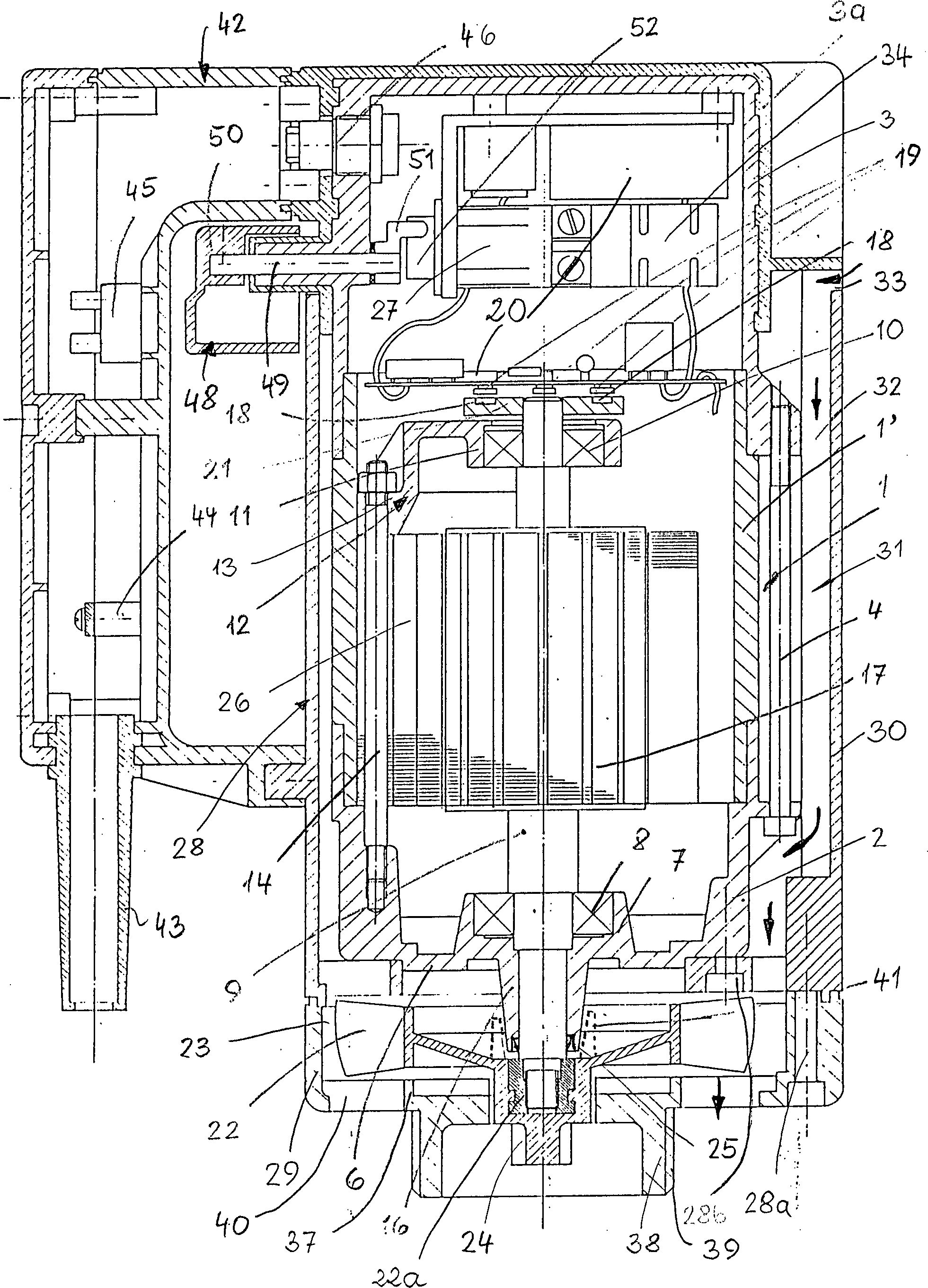
Die Zeichnung zeigt im Längsschnitt einen erfindungsgemäßen Motor für Faß- und Behälterpumpen.The Drawing shows in longitudinal section an engine according to the invention for barrel and container pumps.
Der
Motor hat ein Gehäuse
Der
Gehäuseteil
Die
Gehäuseteile
Der
Motor hat einen Rotor
Die
Rotorwelle
Das
Lüfterrad
Der
Rotor
Der
beschriebene Permanentmagnet-Rotor läuft je nach Belastung zu seinem
umlaufenden Drehfeld um einen kleinen Winkel verschoben synchron
nach. Infolge der Rotorlageerkennung mittels der Magnete
Mit
der Elektronik
Das
Gehäuse
Sie
sind lösbar
mit Schrauben
Die
Luftführungskanäle
Um
eine bessere Wärmeableitung
bei einem metallischen Gehäuse
zu erreichen, kann das Gehäuseteil
Besteht
das Gehäuse
Da
bei der beschriebenen Ausführungsform das
Gehäuse
Bei
dem beschriebenen Motor handelt es sich um einen elektronisch kommutierten
Motor für Faß- und/oder
Behälter pumpen.
Er kann, wenn das Gehäuse
Bei
einem explosionsgeschützten
Motor kann das Gehäuse
auch in zwei Räume
aufgeteilt werden, von denen der eine Raum druckgekapselt und der
andere Raum in Schutzart erhöhte
Sicherheit "e" ausgeführt sein
kann. Im nicht druckgekapselten "Ex
e" Raum kann der
Motor
Zum
Einschalten des Motors ist der Motorschutzschalter
Anstelle
der beschriebenen Radialwellendichtung
Der
beschriebene, an sich bekannte, elektronisch kommutierte Gleichstrommotor
läßt sich
in dem verhältnismäßig kleinen
Innenraum des Gehäuses
Die
Zeichnung zeigt noch den aus Kunststoff bestehenden Griff
Zum
Betätigen
des Motorschutzschalters
Claims (22)
Priority Applications (5)
| Application Number | Priority Date | Filing Date | Title |
|---|---|---|---|
| DE3825035A DE3825035B4 (en) | 1988-07-09 | 1988-07-09 | Brushless, electrically commutated motor for a drum or a container pump to Betieb on an AC voltage network |
| CH2319/89A CH678376A5 (en) | 1988-07-09 | 1989-06-22 | |
| FR8909201A FR2638911B1 (en) | 1988-07-09 | 1989-07-07 | MOTOR FOR A PUMP, IN PARTICULAR A PORTABLE ELECTRIC PUMP OR A SUBMERSIBLE PUMP |
| GB8915575A GB2220800B (en) | 1988-07-09 | 1989-07-07 | An electronically commutated motor for a pump |
| US07/376,759 US5073736A (en) | 1988-07-09 | 1989-07-07 | Brushless pump motor with built-in electronic control |
Applications Claiming Priority (1)
| Application Number | Priority Date | Filing Date | Title |
|---|---|---|---|
| DE3825035A DE3825035B4 (en) | 1988-07-09 | 1988-07-09 | Brushless, electrically commutated motor for a drum or a container pump to Betieb on an AC voltage network |
Publications (2)
| Publication Number | Publication Date |
|---|---|
| DE3825035A1 DE3825035A1 (en) | 1990-01-11 |
| DE3825035B4 true DE3825035B4 (en) | 2006-11-23 |
Family
ID=6359366
Family Applications (1)
| Application Number | Title | Priority Date | Filing Date |
|---|---|---|---|
| DE3825035A Expired - Lifetime DE3825035B4 (en) | 1988-07-09 | 1988-07-09 | Brushless, electrically commutated motor for a drum or a container pump to Betieb on an AC voltage network |
Country Status (5)
| Country | Link |
|---|---|
| US (1) | US5073736A (en) |
| CH (1) | CH678376A5 (en) |
| DE (1) | DE3825035B4 (en) |
| FR (1) | FR2638911B1 (en) |
| GB (1) | GB2220800B (en) |
Families Citing this family (53)
| Publication number | Priority date | Publication date | Assignee | Title |
|---|---|---|---|---|
| US5156535A (en) * | 1990-10-31 | 1992-10-20 | Itt Corporation | High speed whirlpool pump |
| DE4237971B4 (en) * | 1992-11-11 | 2004-05-06 | Unaxis Deutschland Holding Gmbh | Vacuum pump with converter |
| US5349785A (en) * | 1992-11-30 | 1994-09-27 | Black & Decker Inc. | Motor support for orbital polisher |
| JPH06218703A (en) * | 1993-01-22 | 1994-08-09 | Hitachi Koki Co Ltd | Portable electric router |
| US5388958A (en) * | 1993-09-07 | 1995-02-14 | Heat Pipe Technology, Inc. | Bladeless impeller and impeller having internal heat transfer mechanism |
| US5394040A (en) * | 1993-09-07 | 1995-02-28 | Heat Pipe Technology, Inc. | Electric motor having internal heat dissipator |
| EP0645875B2 (en) * | 1993-09-08 | 2001-01-03 | Siemens Aktiengesellschaft | Motor-pump set, in particular antiblocking brake device for automotive vehicles |
| DE4342780A1 (en) * | 1993-12-15 | 1995-06-22 | Siemens Ag | Drive unit |
| FR2737062B1 (en) * | 1995-07-21 | 1997-08-29 | Valeo Climatisation | DEVICE FOR SUPPORTING AN ELECTRIC MOTOR DRIVING A TURBINE, IN PARTICULAR FOR A MOTOR VEHICLE HEATING AND / OR AIR CONDITIONING APPARATUS |
| DE19527879A1 (en) * | 1995-07-29 | 1997-01-30 | Lutz Pumpen Gmbh & Co Kg | Electric motor, in particular drive motor for a drum or container pump |
| SI9600152A (en) * | 1996-05-10 | 1996-12-31 | Iskra Avtoelektrika Nova Goric | Three-phase electronically commutated dc electric motor |
| DE19631517A1 (en) * | 1996-08-03 | 1998-02-05 | Wacker Werke Kg | Variable-speed, hand-held power tool driven by an electric motor that can be connected to single-phase alternating current |
| US6522039B1 (en) * | 1996-12-13 | 2003-02-18 | Illinois Tool Works Inc. | Remote power source for electrostatic paint applicator |
| DE19736364A1 (en) * | 1997-08-21 | 1999-02-25 | Mannesmann Rexroth Ag | Compact hydraulic unit |
| DE19757741B4 (en) * | 1997-12-23 | 2017-09-28 | Flux-Geräte GmbH | Motor for a pump, in particular a drum pump |
| US6133658A (en) * | 1998-01-27 | 2000-10-17 | General Electric Company | Method of voltage selection and bearing protection for an electric motor |
| JP2001128432A (en) * | 1999-09-10 | 2001-05-11 | Jianzhun Electric Mach Ind Co Ltd | Ac power supply drive type dc brushless electric motor |
| KR100440536B1 (en) * | 2000-04-26 | 2004-07-19 | 선온웰스 일렉트릭 머신 인더스트리 컴퍼니 리미티드 | Brushless DC Motor Fan Driven By An AC Power Source |
| DE20105050U1 (en) * | 2000-05-27 | 2001-06-28 | Papst-Motoren GmbH & Co. KG, 78112 St Georgen | Motor arrangement |
| DE10045094A1 (en) * | 2000-09-12 | 2002-03-28 | Siemens Ag | Permanent magnet excited synchronous machine for application in explosion risk areas such as drives in oil and gas industry, comprises part poles or whole poles magnetized by magnetizing units |
| US6600247B1 (en) * | 2000-09-29 | 2003-07-29 | Reliance Electric Technologies, Llc | Motor stator connection method and apparatus |
| US6570284B1 (en) * | 2001-12-11 | 2003-05-27 | Black & Decker Inc. | Brushless motor having double insulation |
| DE10302791B4 (en) * | 2002-01-30 | 2016-03-17 | Denso Corporation | electric compressor |
| DE10317181B4 (en) * | 2003-04-15 | 2006-05-24 | Alexander Schischek | Drive, especially actuator and control drive, for flaps and valves |
| DE10362051B4 (en) * | 2003-08-29 | 2016-05-19 | Sew-Eurodrive Gmbh & Co Kg | Electric motor and method of manufacture |
| DE102004024554B4 (en) * | 2004-05-18 | 2018-01-25 | Pfeiffer Vacuum Gmbh | Oil-sealed rotary vane vacuum pump |
| DE102004024562A1 (en) * | 2004-05-18 | 2005-12-15 | Pfeiffer Vacuum Gmbh | Dry running piston vacuum pump |
| US7687945B2 (en) * | 2004-09-25 | 2010-03-30 | Bluwav Systems LLC. | Method and system for cooling a motor or motor enclosure |
| EP1742334A1 (en) * | 2005-07-06 | 2007-01-10 | Rausch, Hartmuth | Compact drive |
| CA2655134C (en) | 2006-06-07 | 2017-07-04 | A.O. Smith Corporation | Totally enclosed fan cooled motor |
| DE102007034914A1 (en) * | 2007-07-24 | 2009-02-05 | Sew-Eurodrive Gmbh & Co. Kg | Converter motor, has flow channel formed between inner and outer housing parts, and fan wheel arranged on rotor shaft, passing cooling air through channel for cooling motor and power electronics |
| DE102007045350A1 (en) | 2007-09-22 | 2009-04-02 | Lutz Pumpen Gmbh | Electronically commutated motor |
| US8196674B2 (en) * | 2008-03-05 | 2012-06-12 | Makita Corporation | Impact tool |
| CN102149515B (en) | 2009-01-30 | 2014-08-06 | 日立工机株式会社 | electrical tools |
| DE102009016981A1 (en) * | 2009-04-08 | 2010-10-14 | Knorr-Bremse Systeme für Nutzfahrzeuge GmbH | Bistable valve with electromotive actuation |
| JP5436943B2 (en) * | 2009-06-04 | 2014-03-05 | 株式会社マキタ | Electric tool |
| WO2011041403A2 (en) * | 2009-09-29 | 2011-04-07 | A. O. Smith Corporation | Air cooled electric motor |
| WO2011057609A2 (en) * | 2009-11-12 | 2011-05-19 | Conti Temic Microelectronic Gmbh | Control circuit for an electrical drive device and electrical drive device having such a control circuit |
| SE534992C2 (en) * | 2010-07-16 | 2012-03-06 | Bae Systems Haegglunds Ab | Electric drive for motor vehicles |
| US8546984B2 (en) * | 2010-11-03 | 2013-10-01 | Nidec Motor Corporation | Pump motor control assembly |
| DE202011002408U1 (en) * | 2011-02-04 | 2012-05-07 | Ebm-Papst Mulfingen Gmbh & Co. Kg | DC electric motor in explosion-proof design |
| WO2013007225A1 (en) * | 2011-07-08 | 2013-01-17 | Hanning Elekro-Werke Gmbh & Co.Kg | Electric motor |
| JP5652359B2 (en) * | 2011-09-12 | 2015-01-14 | 株式会社豊田自動織機 | Electric compressor |
| FR2984035A1 (en) * | 2011-12-13 | 2013-06-14 | Victor Jean Ballestra | Motor for rotor-stator type pump or sanitary crusher for toilet, has frame made of plastic material for ensuring concentricity of stator-rotor and embedded in another frame made of plastic material resistant to chemical agents |
| CN102644607A (en) * | 2012-04-12 | 2012-08-22 | 广东凌霄泵业股份有限公司 | Submersible pump special for toilet |
| WO2014116576A1 (en) * | 2013-01-28 | 2014-07-31 | Dixon Pumps Inc. | System, apparatus, and method for controlling a motor |
| US20160149467A1 (en) | 2014-11-25 | 2016-05-26 | Black & Decker Inc. | Brushless Motor for a Power Tool |
| US10328566B2 (en) | 2015-10-14 | 2019-06-25 | Black & Decker Inc. | Brushless motor system for power tools |
| US10900583B2 (en) * | 2017-07-17 | 2021-01-26 | Motion Express, Inc. | Explosion proof actuator assembly and servo system |
| TWI678867B (en) * | 2018-07-09 | 2019-12-01 | 群光電能科技股份有限公司 | Integrate motor drive |
| KR102351793B1 (en) * | 2020-04-29 | 2022-01-17 | 엘지전자 주식회사 | Electric motor assembly and hair dryer having the same |
| DE102021000749A1 (en) | 2021-02-13 | 2022-08-18 | Hydac Mobilhydraulik Gmbh | valve device |
| CN115788919A (en) | 2021-09-09 | 2023-03-14 | 创科无线普通合伙 | submersible pump |
Citations (6)
| Publication number | Priority date | Publication date | Assignee | Title |
|---|---|---|---|---|
| DE3012715A1 (en) * | 1980-04-01 | 1981-10-08 | Gerhard Lutz | Explosion proof encapsulated electric motor - has motor, terminal and switch casings lined fully on inside with insulating plastics coating |
| US4511312A (en) * | 1982-07-28 | 1985-04-16 | Institut Cerac S.A. | Method of driving the impeller of a liquid pump by means of a brushless a.c. motor; and a liquid pump for carrying out the method |
| DE3512675A1 (en) * | 1984-04-13 | 1985-10-17 | Etablissements Pompes Guinard S.A., Courbevoie | Motor housing, especially for a submerged pump |
| EP0192469A2 (en) * | 1985-02-19 | 1986-08-27 | Dobson Park Industries Plc | Electric motors and power tools |
| EP0203846A1 (en) * | 1985-05-14 | 1986-12-03 | Elene S.A. | Direct-current multipolar machine for submerged use |
| WO1988009077A1 (en) * | 1987-05-08 | 1988-11-17 | Firma Karl Lutz | Electric motor, in particular a drive motor for a drum pump or submersible pump |
Family Cites Families (15)
| Publication number | Priority date | Publication date | Assignee | Title |
|---|---|---|---|---|
| US2769105A (en) * | 1953-01-26 | 1956-10-30 | Allis Louis Co | Electric motor suitable for use in an atmosphere containing magnetic particles |
| DE1832662U (en) * | 1958-12-09 | 1961-06-08 | Albert Blum | UNDERWATER PUMP. |
| DE2009939A1 (en) * | 1969-03-25 | 1970-10-08 | N.V. Philips' Gloeilampenfabrieken, Eindhoven (Niederlande) | Electrical machine, in particular a brushless direct current motor with a stationary, essentially bobbin-shaped coil |
| FR2379932A1 (en) * | 1977-02-02 | 1978-09-01 | Maihak Ag | Flame proof motor drive circuit - has static inverter with diodes to produce AC from safe low current DC supply |
| CA1103298A (en) * | 1977-02-25 | 1981-06-16 | Masami Uchiyama | Electric motor with discrete rotor position and speed sensors |
| US4172295A (en) * | 1978-01-27 | 1979-10-30 | Shiley Scientific, Inc. | Tri-cuspid three-tissue prosthetic heart valve |
| GB2075240B (en) * | 1980-03-05 | 1985-03-13 | Papst Motoren Kg | Disc storage drive |
| US4348603A (en) * | 1981-01-29 | 1982-09-07 | Black & Decker Inc. | Printed-circuit board and trigger-switch arrangement for a portable electric tool |
| US4692676A (en) * | 1984-03-02 | 1987-09-08 | Matsushita Electric Industrial Co., Ltd. | Sewing machine driving apparatus |
| JPS60186852U (en) * | 1984-05-17 | 1985-12-11 | 三菱電機株式会社 | Electric motor waterproofing device |
| FR2565045B1 (en) * | 1984-05-22 | 1988-02-26 | Sfena | DEVICE FOR DETECTING THE ANGULAR POSITION OF THE ROTOR OF AN ELECTRONICALLY SWITCHED ROTATING ELECTRIC MACHINE |
| JPH0237255Y2 (en) * | 1984-11-27 | 1990-10-09 | ||
| JPS6219770A (en) * | 1985-07-19 | 1987-01-28 | Fanuc Ltd | Motor provided with pulse encoder |
| FR2603667B1 (en) * | 1986-09-10 | 1990-09-28 | Etri Sa | CENTRIFUGAL FAN DRIVEN BY AN ELECTRONICALLY SWITCHED DIRECT CURRENT MOTOR |
| JP2545819B2 (en) * | 1987-01-14 | 1996-10-23 | 日本電装株式会社 | Brushless motor driven fuel pump |
-
1988
- 1988-07-09 DE DE3825035A patent/DE3825035B4/en not_active Expired - Lifetime
-
1989
- 1989-06-22 CH CH2319/89A patent/CH678376A5/de not_active IP Right Cessation
- 1989-07-07 US US07/376,759 patent/US5073736A/en not_active Expired - Lifetime
- 1989-07-07 GB GB8915575A patent/GB2220800B/en not_active Expired - Lifetime
- 1989-07-07 FR FR8909201A patent/FR2638911B1/en not_active Expired - Lifetime
Patent Citations (6)
| Publication number | Priority date | Publication date | Assignee | Title |
|---|---|---|---|---|
| DE3012715A1 (en) * | 1980-04-01 | 1981-10-08 | Gerhard Lutz | Explosion proof encapsulated electric motor - has motor, terminal and switch casings lined fully on inside with insulating plastics coating |
| US4511312A (en) * | 1982-07-28 | 1985-04-16 | Institut Cerac S.A. | Method of driving the impeller of a liquid pump by means of a brushless a.c. motor; and a liquid pump for carrying out the method |
| DE3512675A1 (en) * | 1984-04-13 | 1985-10-17 | Etablissements Pompes Guinard S.A., Courbevoie | Motor housing, especially for a submerged pump |
| EP0192469A2 (en) * | 1985-02-19 | 1986-08-27 | Dobson Park Industries Plc | Electric motors and power tools |
| EP0203846A1 (en) * | 1985-05-14 | 1986-12-03 | Elene S.A. | Direct-current multipolar machine for submerged use |
| WO1988009077A1 (en) * | 1987-05-08 | 1988-11-17 | Firma Karl Lutz | Electric motor, in particular a drive motor for a drum pump or submersible pump |
Also Published As
| Publication number | Publication date |
|---|---|
| FR2638911B1 (en) | 1996-07-19 |
| GB2220800B (en) | 1993-03-31 |
| GB2220800A (en) | 1990-01-17 |
| GB8915575D0 (en) | 1989-08-23 |
| US5073736A (en) | 1991-12-17 |
| FR2638911A1 (en) | 1990-05-11 |
| DE3825035A1 (en) | 1990-01-11 |
| CH678376A5 (en) | 1991-08-30 |
Similar Documents
| Publication | Publication Date | Title |
|---|---|---|
| DE3825035B4 (en) | Brushless, electrically commutated motor for a drum or a container pump to Betieb on an AC voltage network | |
| EP1735893B1 (en) | Electric motor and range of electric motors | |
| EP1160960B1 (en) | Explosion proof motor assembly | |
| EP0317580B1 (en) | Electric motor, in particular a drive motor for a drum pump or submersible pump | |
| DE69009346T2 (en) | Electric motor pump with can. | |
| DE10313273B9 (en) | Electric motor with high IP protection | |
| DE102004033745B4 (en) | electric motor | |
| DE10109797B4 (en) | Inverter motor, comprising a motor, at least one intermediate part and an inverter | |
| DE102006047269A1 (en) | converter motor | |
| DE19824345A1 (en) | Canned tube pump with winding carrier | |
| DE10313274A1 (en) | Electric motor with high IP protection | |
| DE19527879A1 (en) | Electric motor, in particular drive motor for a drum or container pump | |
| EP1936203B1 (en) | Vacuum pump with ventilator | |
| EP1419568B1 (en) | Electric motor with a high ip-protective system | |
| EP0610767A2 (en) | Electric motor, particularly a converter-fed asynchronous motor for propelling motor vehicles | |
| DE102009013363A1 (en) | Stator socket for drive unit of electric motor, particularly electronically communicating direct current motor, has casing and base, which has passage, where passage is limited by circulating lug | |
| DE19634097A1 (en) | Electric motor | |
| DE3012715C2 (en) | Explosion-proof electric motor | |
| DE10133767A1 (en) | Commutator motor with a cylindrical motor housing | |
| EP0877166B1 (en) | Wet suction apparatus | |
| DE202008000225U1 (en) | electric motor | |
| DE8801028U1 (en) | High pressure cleaning device | |
| WO2021116039A1 (en) | Electric motor for a handheld power tool | |
| EP2653729A1 (en) | Radial fan with an auxiliary electromagnetically protected casing for the control electronics | |
| WO2018145817A2 (en) | Motor converter |
Legal Events
| Date | Code | Title | Description |
|---|---|---|---|
| 8110 | Request for examination paragraph 44 | ||
| 8364 | No opposition during term of opposition |