JP5651925B2 - Fiber-reinforced composite material molded article and its manufacturing method - Google Patents
Fiber-reinforced composite material molded article and its manufacturing method Download PDFInfo
- Publication number
- JP5651925B2 JP5651925B2 JP2009106620A JP2009106620A JP5651925B2 JP 5651925 B2 JP5651925 B2 JP 5651925B2 JP 2009106620 A JP2009106620 A JP 2009106620A JP 2009106620 A JP2009106620 A JP 2009106620A JP 5651925 B2 JP5651925 B2 JP 5651925B2
- Authority
- JP
- Japan
- Prior art keywords
- fiber
- resin
- composite material
- reinforced composite
- thermoplastic resin
- Prior art date
- Legal status (The legal status is an assumption and is not a legal conclusion. Google has not performed a legal analysis and makes no representation as to the accuracy of the status listed.)
- Active
Links
Images


Landscapes
- Injection Moulding Of Plastics Or The Like (AREA)
Description
本発明は、繊維強化複合材料成形品とその製造方法に関する。 The present invention relates to a fiber-reinforced composite material molded article and a method for producing the same.
繊維強化複合材料(以下、「FRP」という。)は、軽量で且つ高強度である特徴から、航空機、自動車、スポーツ、レジャー、その他各種工業用途に利用されている。また、FRPは、それを構成する繊維集束体の配向性によって特徴ある異方性光沢を有し、さらに表面に塗装等の処理を施すことによって、深みのある重厚な外観を与える等の特徴を有する。 BACKGROUND ART Fiber reinforced composite materials (hereinafter referred to as “FRP”) are used for aircraft, automobiles, sports, leisure, and other various industrial applications because of their light weight and high strength. In addition, FRP has a characteristic anisotropic gloss due to the orientation of the fiber bundling body constituting the FRP, and further has features such as giving a deep and heavy appearance by applying a treatment such as painting to the surface. Have.
近年、これらの特徴に加え、難燃性を付与したFRPも数多く検討され、各種電気・電子機器筐体から航空機内装品、自動車内装品などへの用途が拡がっている。これら電気・電子機器筐体、航空機内装品、自動車内装品に用いる場合には、外板を形成するFRP板の一方の面に同種のFRPや熱可塑性樹脂、金属材料などを接合一体化した三次元形状の部材を用いる場合が多い。
例えば、特許文献1には、可撓性を有する炭素繊維複合材料板の表面に、熱可塑性樹脂を射出成形して結合一体化せしめた炭素繊維複合成形品が開示されている。
In recent years, in addition to these features, many FRPs imparted with flame retardancy have been studied, and applications from various electrical / electronic equipment casings to aircraft interior parts, automobile interior parts, and the like are expanding. When used in these electrical / electronic equipment casings, aircraft interior parts, and automobile interior parts, a tertiary structure in which the same kind of FRP, thermoplastic resin, metal material, etc. are joined and integrated on one side of the FRP board forming the outer panel. In many cases, original shape members are used.
For example, Patent Document 1 discloses a carbon fiber composite molded article in which a thermoplastic resin is injection-molded and bonded and integrated on the surface of a flexible carbon fiber composite material plate.
しかしながら、特許文献1に記載のように、外板を形成するFRP板の一方の面の全体に、熱可塑性樹脂や金属材料を射出成形して接合すると、FRP板と熱可塑性樹脂や金属材料とでは熱膨張率が異なるため、冷却した際に熱可塑性樹脂や金属材料が収縮し、その反動でFRP板が反る場合があった。FRP板が反ると、電気・電子機器筐体、航空機内装品、自動車内装品や、各種工業品として用いるには不適となる。 However, as described in Patent Document 1, when a thermoplastic resin or a metal material is injection-molded and joined to one whole surface of the FRP plate that forms the outer plate, the FRP plate and the thermoplastic resin or the metal material However, since the coefficient of thermal expansion is different, the thermoplastic resin or the metal material contracts when cooled, and the FRP plate may warp due to the reaction. If the FRP plate is warped, it is unsuitable for use as an electrical / electronic equipment casing, aircraft interior, automobile interior, or various industrial products.
本発明は上記事情に鑑みてなされたもので、熱可塑性樹脂を射出成形しても繊維強化複合材料が反りにくい繊維強化複合材料成形品とその製造方法の提供を課題とする。 The present invention has been made in view of the above circumstances, and an object of the present invention is to provide a fiber-reinforced composite material molded product in which the fiber-reinforced composite material is hardly warped even if the thermoplastic resin is injection-molded, and a method for manufacturing the same.
本発明の繊維強化複合材料成形品は、強化繊維にマトリックス樹脂が含浸した繊維強化複合材料の一方の面の全体に、格子状となるように熱可塑性樹脂を射出成形して接合一体化した繊維強化複合材料成形品であって、格子を形成する熱可塑性樹脂のリブを繊維強化複合材料上に投影したときのリブの占有面積が、全体の1/20〜1/2であることを特徴とする。
また、前記強化繊維が、炭素繊維であることが好ましい。
さらに、前記マトリックス樹脂が、リンを含有するエポキシ樹脂であることが好ましい。
また、前記熱可塑性樹脂が、アクリロニトリル−ブタジエン−スチレン樹脂、またはポリカーボネート樹脂とアクリロニトリル−ブタジエン−スチレン樹脂とのアロイ樹脂であることが好ましい。
さらに、前記接合一体化は、インジェクションプレスによりなされることが好ましい。
Fiber-reinforced composite material molded article of the present invention, the matrix resin in the reinforcing fibers within the entire one surface of the fiber-reinforced composite material impregnated and bonded integrally with the thermoplastic resin so that the grid-like injection molded to fiber A molded article of reinforced composite material , characterized in that the occupied area of the ribs when the ribs of thermoplastic resin forming the lattice are projected onto the fiber reinforced composite material is 1/20 to 1/2 of the whole. To do.
The reinforcing fiber is preferably a carbon fiber.
Furthermore, it is preferable that the matrix resin is an epoxy resin containing phosphorus.
The thermoplastic resin is preferably an acrylonitrile-butadiene-styrene resin or an alloy resin of a polycarbonate resin and acrylonitrile-butadiene-styrene resin.
Furthermore, it is preferable that the joining and integration be performed by an injection press.
また、本発明の繊維強化複合材料成形品の製造方法は、強化繊維にマトリックス樹脂が含浸した繊維強化複合材料の一方の面の全体に、格子状となるように熱可塑性樹脂を射出成形して接合一体化する繊維強化複合材料成形品の製造方法であって、格子を形成する熱可塑性樹脂のリブを繊維強化複合材料上に投影したときのリブの占有面積が、全体の1/20〜1/2となるように熱可塑性樹脂を射出成形することを特徴とする。
さらに、インジェクションプレスにより、前記熱可塑性樹脂を射出成形することが好ましい。
Further, the method for producing a fiber-reinforced composite material molded article of the present invention is such that a thermoplastic resin is injection-molded so as to form a lattice pattern on one side of a fiber-reinforced composite material in which a reinforcing resin is impregnated with a matrix resin. A method for manufacturing a fiber-reinforced composite material molded product to be joined and integrated, wherein the rib occupying area when a rib of thermoplastic resin forming a lattice is projected onto the fiber-reinforced composite material is 1/20 to 1 of the whole A thermoplastic resin is injection-molded so as to be / 2 .
Furthermore, it is preferable to injection-mold the thermoplastic resin by an injection press.
本発明の繊維強化複合材料成形品は、熱可塑性樹脂を射出成形しても繊維強化複合材料が反りにくい。
また、本発明の繊維強化複合材料成形品の製造方法によれば、熱可塑性樹脂を射出成形しても繊維強化複合材料が反りにくい繊維強化複合材料成形品が得られる。
In the fiber-reinforced composite material molded article of the present invention, the fiber-reinforced composite material is unlikely to warp even when the thermoplastic resin is injection-molded.
In addition, according to the method for producing a fiber-reinforced composite material molded article of the present invention, a fiber-reinforced composite material molded article in which the fiber-reinforced composite material is hardly warped even when the thermoplastic resin is injection-molded can be obtained.
以下、本発明について、図面を用いて詳細に説明する。
図1は、本発明の繊維強化複合材料成形品の一例を示す斜視図である。この例の繊維強化複合材料成形品1は、繊維強化複合材料(以下、「FRP」という。)10の一方の面に、格子状となるように射出成形された熱可塑性樹脂20が接合一体化されている。
なお、図2〜8において、図1と同じ構成要素には同じ符号を付して説明を省略する。
Hereinafter, the present invention will be described in detail with reference to the drawings.
FIG. 1 is a perspective view showing an example of a fiber-reinforced composite material molded product of the present invention. The fiber reinforced composite material molded product 1 of this example is formed by joining and integrating a
2-8, the same code | symbol is attached | subjected to the same component as FIG. 1, and description is abbreviate | omitted.
<繊維強化複合材料>
本発明に用いるFRP10としては、強化繊維にマトリックス樹脂が含浸したプリプレグを、必要に応じて複数積層し、高温高圧下で成形したものが挙げられる。
強化繊維としては、炭素繊維、アラミド繊維、ナイロン繊維、高強度ポリエステル繊維、ガラス繊維、ボロン繊維、アルミナ繊維、窒化珪素繊維などの各種の無機繊維または有機繊維を用いることができる。これらの中でも難燃性の観点から炭素繊維、アラミド繊維、ガラス繊維、ボロン繊維、アルミナ繊維、窒化珪素繊維が好ましく、さらに比強度および比弾性に優れる点で炭素繊維が特に好ましい。
強化繊維の形態としては、一方向に引き揃えてもよく、織物、またノンクリンプファブリックでもよい。
<Fiber reinforced composite material>
As FRP10 used for this invention, what laminated | stacked multiple prepregs which the fiber resin impregnated the reinforcement fiber as needed, and shape | molded under high temperature and high pressure is mentioned.
As the reinforcing fiber, various inorganic fibers or organic fibers such as carbon fiber, aramid fiber, nylon fiber, high-strength polyester fiber, glass fiber, boron fiber, alumina fiber, and silicon nitride fiber can be used. Among these, carbon fiber, aramid fiber, glass fiber, boron fiber, alumina fiber, and silicon nitride fiber are preferable from the viewpoint of flame retardancy, and carbon fiber is particularly preferable in terms of excellent specific strength and specific elasticity.
The form of the reinforcing fiber may be aligned in one direction, or may be a woven fabric or a non-crimp fabric.
マトリックス樹脂としては、公知の熱硬化性樹脂または熱可塑性樹脂が挙げられる。
熱硬化性樹脂としては、例えばエポキシ樹脂、フェノール樹脂、ビニルエステル樹脂、ビスマレイミド樹脂、メラミン樹脂、不飽和ポリエステル樹脂等が挙げられる。
熱可塑性樹脂としては、例えばポリアミド(PA)樹脂、アクリロニトリル−ブタジエン−スチレン(ABS)樹脂、アクリロニトリル−エチレン−スチレン(AES)樹脂、アクリロニトリル−スチレン−アクリレート(ASA)樹脂、ポリエチレンテレフタレート(PET)樹脂、ポリカーボネート(PC)樹脂、ポリメチルメタクリレート(PMMA)樹脂、ポリブチレンテレフタレート(PBT)樹脂、ポリエーテルスルフォン(PES)樹脂、ポリフェニレンエーテル(PPE)樹脂、ポリフェニレンスルフィド(PPS)樹脂、ポリエーテルエーテルケトン(PEEK)樹脂、ポリエーテルケトンケトン(PEKK)樹脂、ポリイミド(PI)樹脂、ポリテトラフルオロエチレン(PTFE)樹脂、ポリエーテル樹脂、ポリオレフィン(PO)樹脂、液晶ポリマー樹脂、ポリアリレート樹脂、ポリスルフォン樹脂、ポリアクリロニトリルスチレン(PAS)樹脂、ポリスチレン(PS)樹脂、ポリアクリロニトリル(PAN)樹脂、ポリ塩化ビニル(PVC)樹脂等が挙げられる。
これらの中でも靭性、耐衝撃性に優れる点で熱硬化性樹脂、特にエポキシ樹脂が好ましい。さらに電気・電子機器筐体や航空機・自動車内装品、各種工業品に用いることを考慮すると、難燃性を有する点で、リンを含有するエポキシ樹脂が特に好ましい。
Examples of the matrix resin include known thermosetting resins and thermoplastic resins.
Examples of the thermosetting resin include an epoxy resin, a phenol resin, a vinyl ester resin, a bismaleimide resin, a melamine resin, and an unsaturated polyester resin.
Examples of the thermoplastic resin include polyamide (PA) resin, acrylonitrile-butadiene-styrene (ABS) resin, acrylonitrile-ethylene-styrene (AES) resin, acrylonitrile-styrene-acrylate (ASA) resin, polyethylene terephthalate (PET) resin, Polycarbonate (PC) resin, polymethyl methacrylate (PMMA) resin, polybutylene terephthalate (PBT) resin, polyether sulfone (PES) resin, polyphenylene ether (PPE) resin, polyphenylene sulfide (PPS) resin, polyether ether ketone (PEEK) ) Resin, polyether ketone ketone (PEKK) resin, polyimide (PI) resin, polytetrafluoroethylene (PTFE) resin, polyether resin, polyolefin Resin (PO) resin, liquid crystal polymer resin, polyarylate resin, polysulfone resin, polyacrylonitrile styrene (PAS) resin, polystyrene (PS) resin, polyacrylonitrile (PAN) resin, polyvinyl chloride (PVC) resin, etc. It is done.
Among these, a thermosetting resin, particularly an epoxy resin is preferable in terms of excellent toughness and impact resistance. Furthermore, in consideration of use in electrical / electronic equipment casings, aircraft / automobile interior parts, and various industrial products, epoxy resins containing phosphorus are particularly preferable in terms of flame retardancy.
<熱可塑性樹脂>
FRP10の表面に射出成形する熱可塑性樹脂20としては、例えばマトリックス樹脂の説明において先に例示した熱可塑性樹脂や、ポリビニルフォルマール(PVF)、あるいはこれらの樹脂を組み合わせてなるアロイ樹脂等、射出成形できる樹脂であればよく、FRPとの接着性を考慮して適宜選定して使用することができる。これらの中でも、靭性・汎用性に優れる点で、ABS樹脂、AES樹脂、ASA樹脂、ポリアミド樹脂、PC樹脂とABS樹脂とのアロイ樹脂、PC樹脂とAES樹脂とのアロイ樹脂、PC樹脂とASA樹脂とのアロイ樹脂が好適であり、特にABS樹脂、PC樹脂とABS樹脂とのアロイ樹脂が適している。
また、FRP10の表面に射出成形する熱可塑性樹脂20には、強化繊維、強化充填材、難燃剤、着色剤、安定剤等の添加剤を適宜配合してもよい。
<Thermoplastic resin>
Examples of the
Moreover, you may mix | blend suitably additives, such as a reinforced fiber, a reinforcement filler, a flame retardant, a coloring agent, a stabilizer, with the
本発明の繊維強化複合材料成形品1は、熱可塑性樹脂20がFRP10の一方の面に格子状に射出成形され接合一体化してなる。熱可塑性樹脂を格子状に射出成形することで、従来のようにFRPの一方の面の全体に、熱可塑性樹脂を厚さが均一になるように射出成形する場合に比べて、FRPに対する熱可塑性樹脂の割合が少なくなる。従って、FRPと熱可塑性樹脂との熱膨張率差が軽減され、FRPが反るのを抑制できる。
図1に示すように、格子は熱可塑性樹脂20のリブ21により形成される。格子の高さH1は3〜20mmが好ましい。格子の高さH1が3mm以上であれば、補強部材として充分な剛性が得られる。一方、格子の高さH1が20mm以下であれば、FRPと熱可塑性樹脂との熱膨張率差によるFRPの反りを抑制しやすくなる。
The fiber-reinforced composite material molded article 1 of the present invention is formed by injection-molding a
As shown in FIG. 1, the lattice is formed by
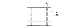
また、例えば図2に示すように、格子を形成するリブをFRP10上に投影したときのリブ21の占有面積は、全体の1/20〜1/2であることが好ましい。リブ21の占有面積が全体の1/20以上であれば、FRPの補強効果を充分に高めることができる。一方、リブ21の占有面積が全体の1/2以下であれば、熱可塑性樹脂を射出成形した後のFRPの反りを抑制しやすくなると共に、得られる繊維強化複合材料成形品の軽量化や、熱可塑性樹脂の使用量の削減につながる。
なお、図2は図1に示す形状の格子を形成するリブ21をFRP上に投影したときの状態を表す図である。
For example, as shown in FIG. 2, the area occupied by the
FIG. 2 is a diagram showing a state when the
格子の形状としては特に制限されず、リブの占有面積が上述した範囲内となるような形状が好ましい。例えば図1に示すような四角状の他、図3(a)に示すような筋状、図3(b)に示すようなハニカム状、図3(c)に示すような円状などが挙げられる。これらの中でも補強効果と金型作製の容易さを考慮すると、図1に示すような四角状の格子が好ましい。 The shape of the lattice is not particularly limited, and a shape in which the occupied area of the rib is within the above-described range is preferable. For example, in addition to a square shape as shown in FIG. 1, a stripe shape as shown in FIG. 3A, a honeycomb shape as shown in FIG. 3B, a circular shape as shown in FIG. It is done. Among these, a square lattice as shown in FIG. 1 is preferable in consideration of the reinforcing effect and the ease of mold production.
格子の形状が図1に示すような四角状の場合、格子のピッチPは10〜100mmが好ましい。格子のピッチPが10mm以上であれば、熱可塑性樹脂を射出成形した後のFRPの反りを抑制しやすくなると共に、得られる繊維強化複合材料成形品の軽量化や、熱可塑性樹脂の使用量の削減につながる。一方、格子のピッチPが100mm以下であれば、FRPの補強効果を充分に高めることができる。
格子の形状が四角状の場合、縦方向と横方向のピッチが等しい正方形が最適であるが、長方形であってもよい。
When the shape of the lattice is a square as shown in FIG. 1, the lattice pitch P is preferably 10 to 100 mm. If the pitch P of the lattice is 10 mm or more, it becomes easy to suppress the warpage of the FRP after the injection molding of the thermoplastic resin, the weight reduction of the obtained fiber-reinforced composite material molded product, and the amount of the thermoplastic resin used It leads to reduction. On the other hand, if the pitch P of the lattice is 100 mm or less, the reinforcing effect of FRP can be sufficiently enhanced.
When the shape of the lattice is a square, a square having the same vertical and horizontal pitches is optimal, but a rectangular shape may be used.
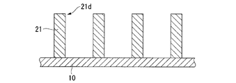
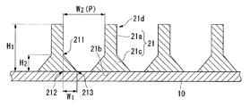
格子を形成するリブ21の断面形状としては、図4に示すような長方形の他、図5に示すように長方形の柱状部21aと、FRP10との接合面21bに向かって末広な底部21cとからなる形状、図6に示すように長方形の柱状部21aと、FRP10との接合面21bに向かって末広な底部21cとからなり、かつ隣り合うリブ21の接合面21bが連結している形状などが挙げられる。特に図5、6に示すような断面形状であれば、FRP10とリブ21との接着性がより向上する。
また、リブ21の先端21dは、図4〜6に示すような非テーパー状に限定されず、テーパー状であってもよいし、逆釣鐘状であってもよい。
As the cross-sectional shape of the
Further, the
なお、リブ21の断面形状が図5に示す形状の場合、底部21cの高さH2は、リブ21の高さ(すなわち、格子の高さH1)の1/10〜8/10倍が好ましい。また、底部21cの起点211を通る線が接合面21bと直交する点212から、底部21cの終点213までの距離をW1、隣り合うリブ21の距離をW2としたときに、距離W1は距離W2の1/50〜1/2倍が好ましい。なお、距離W2は、格子のピッチPに相当する。
In the case the cross-sectional shape of the
また、リブ21の断面形状が図6に示す形状の場合、底部21cの高さH2は、リブ21の高さ(すなわち、格子の高さH1)の1/10〜8/10倍が好ましい。また、隣り合うリブ21の連結点214から接合面21bまでの距離H3は、底部21cの高さH2の1/10〜8/10倍が好ましい。さらに、底部21cの起点211を通る線と、連結点214を通る線が直交する点215から連結点214までの距離W3は、隣り合うリブ21の距離W2の1/50〜1/2倍が好ましい。
Also, if the cross-sectional shape of the
<繊維強化複合材料成形品の製造方法>
本発明の繊維強化複合材料成形品は、以下のようにして製造できる。
すなわち、所望の格子状に熱可塑性樹脂を射出成形できる金型にFRPを入れ、熱可塑性樹脂を射出成形し、FRPと熱可塑性樹脂が接合一体化した繊維強化複合材料形成品を得る。
射出条件としては特に制限されず、用いるFRPや熱可塑性樹脂の種類や、金型の形状に合わせて適宜設定すればよい。
<Production method of fiber-reinforced composite material molded product>
The fiber-reinforced composite material molded article of the present invention can be produced as follows.
That is, FRP is put into a mold capable of injection-molding a thermoplastic resin in a desired lattice shape, the thermoplastic resin is injection-molded, and a fiber-reinforced composite material-formed product in which FRP and the thermoplastic resin are bonded and integrated is obtained.
The injection conditions are not particularly limited, and may be set as appropriate according to the type of FRP and thermoplastic resin used and the shape of the mold.
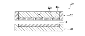
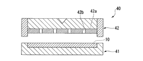
金型としては特に制限されず、例えば図4に示す断面形状のリブ21により格子を形成する場合は、図7に示すようなFRP10を設置する下型31と、凸部32aおよび凹部32bを有する上型32からなる金型30を用いればよい。また、リブの接合面が連結している断面形状のリブにより格子を形成する場合は、例えば図8に示すようなFRP10を設置する下型41と、凸部42aおよび凹部42bを有する上型42からなり、下型41と上型42が合わさったときに、FRP10と凸部42aの間に空隙が形成される金型40を用いればよい。
The mold is not particularly limited. For example, when the lattice is formed by the
本発明の繊維強化複合材料成形品は、既存の射出成形機を用いて製造できるが、大型成形品の成形が可能であり、FRPと熱可塑性樹脂との接着性がより強固となる点で、インジェクションプレスを用いることが好ましい。 The fiber-reinforced composite material molded product of the present invention can be manufactured using an existing injection molding machine, but can be molded into a large molded product, and the adhesiveness between the FRP and the thermoplastic resin becomes stronger. It is preferable to use an injection press.
以上説明したように、本発明によれば、FRPの一方の面に、熱可塑性樹脂を格子状に射出成形することで、従来のようにFRPの一方の面の全体に、熱可塑性樹脂を厚さが均一になるように射出成形する場合に比べて、FRPに対する熱可塑性樹脂の割合が少なくなる。従って、FRPと熱可塑性樹脂との熱膨張率差が軽減され、FRPが反るのを抑制できる。
また、本発明により得られる繊維強化複合材料成形品は、FRP本来の特性、すなわち軽量で、優れた強度、剛性、寸法安定性、耐久性、衝撃吸収性を発現できると共に、FRP特有の深みのある重厚な外観を有する。
As described above, according to the present invention, the thermoplastic resin is thickly formed on one surface of the FRP by conventional injection molding in a lattice shape on one surface of the FRP. The ratio of the thermoplastic resin to FRP is smaller than in the case of injection molding so that the thickness is uniform. Therefore, the difference in thermal expansion coefficient between the FRP and the thermoplastic resin is reduced, and the FRP can be prevented from warping.
In addition, the fiber-reinforced composite material molded product obtained by the present invention has the characteristics inherent to FRP, that is, light weight, excellent strength, rigidity, dimensional stability, durability, shock absorption, and a depth unique to FRP. Has a heavy appearance.
以下、本発明について実施例を挙げて具体的に説明する。ただし、本発明はこれらに限定されるものではない。 Hereinafter, the present invention will be specifically described with reference to examples. However, the present invention is not limited to these.
[実施例1]
<FRPの作製>
プリプレグ(三菱レイヨン株式会社製のパイロフィルプリプレグ、「品番:TR380G200S」、繊維目付200g/m2、樹脂含有率33質量%)を300mm×300mmに切断し、炭素繊維が0°/90°/90°/0°の向きになるよう4枚積み重ね、130℃×90分、昇温速度2℃/分、圧力0.6MPaの条件でオートクレーブにて硬化し、厚さ0.8mmのFRPを得た。
[Example 1]
<FRP production>
A prepreg (Pyrofil prepreg manufactured by Mitsubishi Rayon Co., Ltd., “product number: TR380G200S”, fiber basis weight 200 g / m 2 , resin content 33 mass%) is cut into 300 mm × 300 mm, and the carbon fiber is 0 ° / 90 ° / 90. 4 sheets were stacked so that the orientation was at 0 ° / 0 °, and cured in an autoclave under conditions of 130 ° C. × 90 minutes, heating rate 2 ° C./minute, pressure 0.6 MPa, and 0.8 mm thick FRP was obtained. .
<繊維強化複合材料成形品の製造>
得られたFRPを280mm×220mmに切断して金型底部にセットし、熱可塑性樹脂(UMGABS株式会社製の難燃性PC樹脂とABS樹脂のアロイ樹脂、「品番:CX55A」)を、シリンダー温度230℃、金型温度60℃の条件で、図1に示すように、格子の高さH1が5mm、格子のピッチPが50mm、格子を形成するリブをFRP上に投影したときのリブの占有面積が全体の8%になるように、FRPの一方の面に四角格子状に射出成形して、FRP10(厚さT1:0.8mm)と熱可塑性樹脂20とが接合一体化した繊維強化複合材料成形品1を得た。
<Manufacture of fiber reinforced composite material molded products>
The obtained FRP was cut into 280 mm × 220 mm and set at the bottom of the mold, and a thermoplastic resin (flammable PC resin made by UMGABS Co., Ltd. and an alloy resin of ABS resin, “Product No .: CX55A”) was applied to the cylinder temperature As shown in FIG. 1, under the conditions of 230 ° C. and mold temperature of 60 ° C., the grating height H 1 is 5 mm, the grating pitch P is 50 mm, and the ribs formed when the ribs forming the grating are projected onto the FRP A fiber in which FRP 10 (thickness T 1 : 0.8 mm) and
得られた繊維強化複合材料成形品は冷却した後もFRPが反ることはなかった。また、熱可塑性樹脂側を下向きにして置き、上部よりFRPの中心部に50Nの荷重を加えても撓むことがなかった。
また、外観はFRP特有の高級重厚感を有し、電気・電子機器筐体や航空機・自動車内装品をはじめ各種工業用品へ有効に利用できるものであった。
The obtained fiber reinforced composite material molded article did not warp the FRP even after cooling. Moreover, even when a 50N load was applied from the top to the center of the FRP, the thermoplastic resin side was not bent.
In addition, the appearance has a high-class profound feeling peculiar to FRP, and can be effectively used for various industrial products such as electrical and electronic equipment casings, aircraft and automobile interior parts.
[実施例2]
図5に示す断面形状のリブになるように、熱可塑性樹脂を格子状に射出成形した以外は、実施例1と同様にしてFRPと熱可塑性樹脂とが接合一体化した繊維強化複合材料成形品を得た。なお、形成されたリブは、格子の高さH1が5mm、格子のピッチP(隣り合うリブ21の距離W2)が50mm、底部21cの高さH2が2mm、距離W1が4mm、リブをFRP上に投影したときのリブの占有面積が全体の36%であった。
得られた繊維強化複合材料成形品は、実施例1と同様に冷却した後もFRPが反ることはなかった。また、熱可塑性樹脂側を下向きにして置き、上部よりFRPの中心部に50Nの荷重を加えても撓むことがなかった。
また、外観はFRP特有の高級重厚感を有し、電気・電子機器筐体や航空機・自動車内装品をはじめ各種工業用品へ有効に利用できるものであった。
[Example 2]
A fiber reinforced composite material molded article in which FRP and a thermoplastic resin are joined and integrated in the same manner as in Example 1 except that the thermoplastic resin is injection-molded in a lattice shape so that the rib has the cross-sectional shape shown in FIG. Got. Incidentally, the formed rib height H 1 is 5mm grid, is 50 mm (distance W 2 between the adjacent ribs 21) grating of pitch P, height H 2 is
The obtained fiber-reinforced composite material molded article did not warp FRP even after cooling in the same manner as in Example 1. Moreover, even when a 50N load was applied from the top to the center of the FRP, the thermoplastic resin side was not bent.
In addition, the appearance has a high-class profound feeling peculiar to FRP, and can be effectively used for various industrial products such as electrical and electronic equipment casings, aircraft and automobile interior parts.
[実施例3]
FRP用のプリプレグとして、一方向に引き揃えた炭素繊維(三菱レイヨン株式会社製、「品番:TR50S15L」)にリンを含有するエポキシ樹脂が含浸したプリプレグ(繊維目付225g/m2、樹脂含有率30質量%)4枚を用いた以外は、実施例1と同様にしてFRPを作製し、該FRPと熱可塑性樹脂とが接合一体化した繊維強化複合材料成形品を得た。
得られた繊維強化複合材料成形品は、実施例1と同様に冷却した後もFRPが反ることはなかった。また、熱可塑性樹脂側を下向きにして置き、上部よりFRPの中心部に50Nの荷重を加えても撓むことがなかった。
また、外観はFRP特有の高級重厚感を有し、電気・電子機器筐体や航空機・自動車内装品をはじめ各種工業用品へ有効に利用できるものであった。
[Example 3]
As a prepreg for FRP, a prepreg (fiber basis weight 225 g / m 2 , resin content 30) impregnated with an epoxy resin containing phosphorus in carbon fiber (Mitsubishi Rayon Co., Ltd., “Product No .: TR50S15L”) aligned in one direction. FRP was produced in the same manner as in Example 1 except that 4 sheets (mass%) were used, and a fiber-reinforced composite material molded article in which the FRP and the thermoplastic resin were joined and integrated was obtained.
The obtained fiber-reinforced composite material molded article did not warp FRP even after cooling in the same manner as in Example 1. Moreover, even when a 50N load was applied from the top to the center of the FRP, the thermoplastic resin side was not bent.
In addition, the appearance has a high-class profound feeling peculiar to FRP, and can be effectively used for various industrial products such as electrical and electronic equipment casings, aircraft and automobile interior parts.
[実施例4]
熱可塑性樹脂として、炭素繊維強化ASA樹脂とPC樹脂とのアロイ樹脂(UMGABS株式会社製、「品番:FA−420CA」)を用いた以外は、実施例1と同様にしてFRPと熱可塑性樹脂とが接合一体化した繊維強化複合材料成形品を得た。
得られた繊維強化複合材料成形品は、実施例1と同様に冷却した後もFRPが反ることはなかった。また、熱可塑性樹脂側を下向きにして置き、上部よりFRPの中心部に50Nの荷重を加えても撓むことがなかった。
また、外観はFRP特有の高級重厚感を有し、電気・電子機器筐体や航空機・自動車内装品をはじめ各種工業用品へ有効に利用できるものであった。
[Example 4]
As the thermoplastic resin, FRP and thermoplastic resin were used in the same manner as in Example 1 except that an alloy resin of carbon fiber reinforced ASA resin and PC resin (UMGABS Co., Ltd., “Part No .: FA-420CA”) was used. A fiber-reinforced composite material molded product was obtained.
The obtained fiber-reinforced composite material molded article did not warp FRP even after cooling in the same manner as in Example 1. Moreover, even when a 50N load was applied from the top to the center of the FRP, the thermoplastic resin side was not bent.
In addition, the appearance has a high-class profound feeling peculiar to FRP, and can be effectively used for various industrial products such as electrical and electronic equipment casings, aircraft and automobile interior parts.
[比較例1]
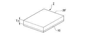
図9に示すように、熱可塑性樹脂の厚さT2が5mmになるように、FRPの一方の面の全体に熱可塑性樹脂を均一に射出成形して、FRP10と熱可塑性樹脂20’とが接合一体化した繊維強化複合材料成形品2を得た。
得られた繊維強化複合材料成形品を室温まで冷却したところ、熱可塑性樹脂がより強く収縮してFRPが大きく反り、繊維強化複合材料成形品全体としても大きく反ってしまった。
[Comparative Example 1]
As shown in FIG. 9, so that the thickness T 2 of the thermoplastic resin is 5 mm, uniformly injection-molding a thermoplastic resin on the entire one surface of the FRP, although the FRP10 and the thermoplastic resin 20 ' A fiber-reinforced composite material molded product 2 joined and integrated was obtained.
When the obtained fiber reinforced composite material molded product was cooled to room temperature, the thermoplastic resin contracted more strongly and the FRP warped greatly, and the fiber reinforced composite material molded product as a whole warped greatly.
1:繊維強化複合材料成形品、
10:繊維強化複合材料、
20:熱可塑性樹脂、
21:リブ。
1: Fiber reinforced composite material molded product,
10: Fiber reinforced composite material,
20: thermoplastic resin,
21: Rib.
Claims (8)
格子を形成する熱可塑性樹脂のリブを繊維強化複合材料上に投影したときのリブの占有面積が、全体の1/20〜1/2である、繊維強化複合材料成形品。 A fiber-reinforced composite material molded product in which a thermoplastic resin is injection-molded and joined and integrated into a lattice shape on one side of a fiber-reinforced composite material in which a reinforced fiber is impregnated with a matrix resin ,
A molded article of fiber reinforced composite material, wherein the rib occupying area is 1/20 to 1/2 of the whole when a rib of thermoplastic resin forming a lattice is projected onto the fiber reinforced composite material.
格子を形成する熱可塑性樹脂のリブを繊維強化複合材料上に投影したときのリブの占有面積が、全体の1/20〜1/2となるように熱可塑性樹脂を射出成形する、繊維強化複合材料成形品の製造方法。 A method for producing a fiber-reinforced composite material molded article in which a thermoplastic resin is injection-molded and joined and integrated into a lattice shape on one side of a fiber-reinforced composite material in which a reinforced fiber is impregnated with a matrix resin. ,
A fiber reinforced composite in which thermoplastic resin is injection-molded so that the rib occupying area is 1/20 to 1/2 of the whole when the ribs of thermoplastic resin forming the lattice are projected onto the fiber reinforced composite material Manufacturing method of material molded product.
Priority Applications (1)
| Application Number | Priority Date | Filing Date | Title |
|---|---|---|---|
| JP2009106620A JP5651925B2 (en) | 2009-04-24 | 2009-04-24 | Fiber-reinforced composite material molded article and its manufacturing method |
Applications Claiming Priority (1)
| Application Number | Priority Date | Filing Date | Title |
|---|---|---|---|
| JP2009106620A JP5651925B2 (en) | 2009-04-24 | 2009-04-24 | Fiber-reinforced composite material molded article and its manufacturing method |
Publications (2)
| Publication Number | Publication Date |
|---|---|
| JP2010253802A JP2010253802A (en) | 2010-11-11 |
| JP5651925B2 true JP5651925B2 (en) | 2015-01-14 |
Family
ID=43315296
Family Applications (1)
| Application Number | Title | Priority Date | Filing Date |
|---|---|---|---|
| JP2009106620A Active JP5651925B2 (en) | 2009-04-24 | 2009-04-24 | Fiber-reinforced composite material molded article and its manufacturing method |
Country Status (1)
| Country | Link |
|---|---|
| JP (1) | JP5651925B2 (en) |
Cited By (2)
| Publication number | Priority date | Publication date | Assignee | Title |
|---|---|---|---|---|
| JP2703664B2 (en) | 1993-09-30 | 1998-01-26 | コンパニー ゼネラール デ エタブリッスマン ミシュラン−ミシュラン エ コムパニー | Tire with radial carcass reinforcement |
| CN107405808A (en) * | 2015-03-30 | 2017-11-28 | 三菱化学株式会社 | Molded body and its manufacturing method |
Families Citing this family (5)
| Publication number | Priority date | Publication date | Assignee | Title |
|---|---|---|---|---|
| EP2669076A1 (en) * | 2012-05-31 | 2013-12-04 | Basf Se | Method for connecting two plastic elements to form a single component |
| US9302434B2 (en) * | 2013-12-03 | 2016-04-05 | The Boeing Company | Thermoplastic composite support structures with integral fittings and method |
| JP6357833B2 (en) * | 2014-03-31 | 2018-07-18 | 東レ株式会社 | Manufacturing method of composite molded product |
| JP6212764B1 (en) * | 2016-05-16 | 2017-10-18 | 石川県 | Fiber reinforced resin sandwich structure and method for manufacturing fiber reinforced resin sandwich structure |
| JPWO2023182258A1 (en) | 2022-03-25 | 2023-09-28 |
Family Cites Families (15)
| Publication number | Priority date | Publication date | Assignee | Title |
|---|---|---|---|---|
| JPS56151550A (en) * | 1980-04-25 | 1981-11-24 | Toyota Motor Co Ltd | Automobile shell-plate panel in synthetic resin and its manufacture |
| JPH0592441A (en) * | 1991-10-02 | 1993-04-16 | Sumitomo Rubber Ind Ltd | Sound-insulating panel |
| JP3035409B2 (en) * | 1992-06-30 | 2000-04-24 | 三菱レイヨン株式会社 | Manufacturing method of carbon fiber composite molded product |
| JPH1134105A (en) * | 1997-07-24 | 1999-02-09 | Mitsubishi Rayon Co Ltd | Fiber-reinforced hollow molded article and method for producing the same |
| JP4628582B2 (en) * | 2001-04-26 | 2011-02-09 | パナソニック株式会社 | Electronic device casing and electronic device using the same |
| JP2004042554A (en) * | 2002-07-15 | 2004-02-12 | Asahi Kasei Chemicals Corp | Housing parts and their injection molding method |
| JP3963268B2 (en) * | 2002-12-03 | 2007-08-22 | 河西工業株式会社 | Manufacturing method for interior parts for automobiles |
| JP2007110138A (en) * | 2002-12-27 | 2007-04-26 | Toray Ind Inc | Molded object for electromagnetic wave shielding and method of manufacturing the same |
| JP2005239939A (en) * | 2004-02-27 | 2005-09-08 | Toray Ind Inc | Fiber reinforced resin composite material |
| US8021752B2 (en) * | 2004-02-27 | 2011-09-20 | Toray Industries, Inc. | Epoxy resin composition for carbon-fiber-reinforced composite material, prepreg, integrated molding, fiber-reinforced composite sheet, and casing for electrical/electronic equipment |
| JP2007290323A (en) * | 2006-04-27 | 2007-11-08 | Japan Polypropylene Corp | Injection molded body |
| JP4789256B2 (en) * | 2006-07-04 | 2011-10-12 | 大成プラス株式会社 | Integral product of fiber reinforced plastic and thermoplastic resin molded product and its manufacturing method |
| JP4762072B2 (en) * | 2006-07-21 | 2011-08-31 | 株式会社仲田コーティング | 畦 Block manufacturing method |
| CN101193506B (en) * | 2006-11-22 | 2011-03-30 | 深圳富泰宏精密工业有限公司 | Electronic device shell and its making method |
| JP2008238624A (en) * | 2007-03-28 | 2008-10-09 | Toray Ind Inc | Polyamide resin structure and its manufacturing method |
-
2009
- 2009-04-24 JP JP2009106620A patent/JP5651925B2/en active Active
Cited By (2)
| Publication number | Priority date | Publication date | Assignee | Title |
|---|---|---|---|---|
| JP2703664B2 (en) | 1993-09-30 | 1998-01-26 | コンパニー ゼネラール デ エタブリッスマン ミシュラン−ミシュラン エ コムパニー | Tire with radial carcass reinforcement |
| CN107405808A (en) * | 2015-03-30 | 2017-11-28 | 三菱化学株式会社 | Molded body and its manufacturing method |
Also Published As
| Publication number | Publication date |
|---|---|
| JP2010253802A (en) | 2010-11-11 |
Similar Documents
| Publication | Publication Date | Title |
|---|---|---|
| JP5651925B2 (en) | Fiber-reinforced composite material molded article and its manufacturing method | |
| JP5917411B2 (en) | Sheet molding compound with core | |
| JP5934802B2 (en) | Load bearing structure and process for aircraft engines | |
| JP7249404B2 (en) | Composite material panel structure and manufacturing method thereof | |
| EP3147108B1 (en) | Carbon fiber composite material | |
| JP2014125532A5 (en) | ||
| CN102785627A (en) | A layer structure composite material bumper with panel composite and its preparation method | |
| KR20120081976A (en) | Resin laminated plate | |
| JP2015178241A (en) | Method of producing fiber-reinforced resin material | |
| WO2022260186A1 (en) | Laminate for pressing, and pressed laminate | |
| KR101932635B1 (en) | Composite material article manufacturing method | |
| JP6229197B2 (en) | Molded product and manufacturing method thereof | |
| JPWO2017222024A1 (en) | Sheet | |
| JP2006213059A (en) | Method for manufacturing FRP composites | |
| JP5648270B2 (en) | Fiber-reinforced composite material molded article and its manufacturing method | |
| CN106687271B (en) | Method for producing a multi-shell composite member with integrated reinforcement structure and multi-shell composite member produced therefrom | |
| JP2021112849A (en) | Laminate and method for producing laminate | |
| KR101237614B1 (en) | Zipper lock type silicone bag for molding composite materials | |
| US11453446B2 (en) | Fiber-reinforced plastics component with plastics foam structure | |
| JP2014162858A (en) | Prepreg and production method of the same, and fiber reinforced composite material | |
| WO2022209455A1 (en) | Flat lightweight member and method for producing same | |
| JP2007131697A (en) | Fiber-reinforced thermoplastic resin stampable sheet and fiber-reinforced thermoplastic resin molded product | |
| JP5179952B2 (en) | Hollow molded product and method for producing hollow molded product | |
| JP2006218782A (en) | Method for molding FRP molded product having foam core | |
| JP6596895B2 (en) | Composite material compact |
Legal Events
| Date | Code | Title | Description |
|---|---|---|---|
| A621 | Written request for application examination |
Free format text: JAPANESE INTERMEDIATE CODE: A621 Effective date: 20120330 |
|
| A977 | Report on retrieval |
Free format text: JAPANESE INTERMEDIATE CODE: A971007 Effective date: 20130806 |
|
| A131 | Notification of reasons for refusal |
Free format text: JAPANESE INTERMEDIATE CODE: A131 Effective date: 20130813 |
|
| A02 | Decision of refusal |
Free format text: JAPANESE INTERMEDIATE CODE: A02 Effective date: 20140610 |
|
| A521 | Written amendment |
Free format text: JAPANESE INTERMEDIATE CODE: A523 Effective date: 20140903 |
|
| A911 | Transfer to examiner for re-examination before appeal (zenchi) |
Free format text: JAPANESE INTERMEDIATE CODE: A911 Effective date: 20140911 |
|
| TRDD | Decision of grant or rejection written | ||
| A01 | Written decision to grant a patent or to grant a registration (utility model) |
Free format text: JAPANESE INTERMEDIATE CODE: A01 Effective date: 20141021 |
|
| A61 | First payment of annual fees (during grant procedure) |
Free format text: JAPANESE INTERMEDIATE CODE: A61 Effective date: 20141103 |
|
| R151 | Written notification of patent or utility model registration |
Ref document number: 5651925 Country of ref document: JP Free format text: JAPANESE INTERMEDIATE CODE: R151 |
|
| S533 | Written request for registration of change of name |
Free format text: JAPANESE INTERMEDIATE CODE: R313533 |
|
| R350 | Written notification of registration of transfer |
Free format text: JAPANESE INTERMEDIATE CODE: R350 |
|
| R250 | Receipt of annual fees |
Free format text: JAPANESE INTERMEDIATE CODE: R250 |
|
| R250 | Receipt of annual fees |
Free format text: JAPANESE INTERMEDIATE CODE: R250 |
|
| R250 | Receipt of annual fees |
Free format text: JAPANESE INTERMEDIATE CODE: R250 |