JP5648592B2 - Corrugated tube with path maintenance member and wire harness - Google Patents
Corrugated tube with path maintenance member and wire harness Download PDFInfo
- Publication number
- JP5648592B2 JP5648592B2 JP2011134792A JP2011134792A JP5648592B2 JP 5648592 B2 JP5648592 B2 JP 5648592B2 JP 2011134792 A JP2011134792 A JP 2011134792A JP 2011134792 A JP2011134792 A JP 2011134792A JP 5648592 B2 JP5648592 B2 JP 5648592B2
- Authority
- JP
- Japan
- Prior art keywords
- corrugated tube
- path
- wire harness
- maintaining member
- slit
- Prior art date
- Legal status (The legal status is an assumption and is not a legal conclusion. Google has not performed a legal analysis and makes no representation as to the accuracy of the status listed.)
- Expired - Fee Related
Links
- 238000012423 maintenance Methods 0.000 title claims description 34
- 230000002093 peripheral effect Effects 0.000 description 21
- 229920001971 elastomer Polymers 0.000 description 8
- 238000005452 bending Methods 0.000 description 5
- 239000000806 elastomer Substances 0.000 description 4
- 238000000034 method Methods 0.000 description 4
- 239000011347 resin Substances 0.000 description 4
- 229920005989 resin Polymers 0.000 description 4
- 238000004519 manufacturing process Methods 0.000 description 3
- 239000004033 plastic Substances 0.000 description 3
- XEEYBQQBJWHFJM-UHFFFAOYSA-N Iron Chemical compound [Fe] XEEYBQQBJWHFJM-UHFFFAOYSA-N 0.000 description 2
- 239000002390 adhesive tape Substances 0.000 description 2
- 238000009434 installation Methods 0.000 description 2
- 239000002184 metal Substances 0.000 description 2
- 229910052751 metal Inorganic materials 0.000 description 2
- 230000004048 modification Effects 0.000 description 2
- 238000012986 modification Methods 0.000 description 2
- 230000001105 regulatory effect Effects 0.000 description 2
- RYGMFSIKBFXOCR-UHFFFAOYSA-N Copper Chemical compound [Cu] RYGMFSIKBFXOCR-UHFFFAOYSA-N 0.000 description 1
- 229910045601 alloy Inorganic materials 0.000 description 1
- 239000000956 alloy Substances 0.000 description 1
- 230000002452 interceptive effect Effects 0.000 description 1
- 229910052742 iron Inorganic materials 0.000 description 1
- 239000000463 material Substances 0.000 description 1
- 230000003287 optical effect Effects 0.000 description 1
- 230000001012 protector Effects 0.000 description 1
- 229910001220 stainless steel Inorganic materials 0.000 description 1
Images

Landscapes
- Rigid Pipes And Flexible Pipes (AREA)
- Details Of Indoor Wiring (AREA)
Description
この発明は、電線を覆いつつその経路を一定に維持する技術に関する。 The present invention relates to a technique for keeping a route constant while covering an electric wire.
従来より、特許文献1〜4に開示のように、車両等に敷設されるワイヤーハーネスを、屈曲性良好なコルゲートチューブにて覆う技術が知られている。
Conventionally, as disclosed in
しかしながら、コルゲートチューブ自体は、屈曲性に優れるもの故、ワイヤーハーネスの経路を一定に維持することはできない。このため、ワイヤーハーネス或はコルゲートチューブに取付けられたクランプ部材を車両の一定位置に固定することで、ワイヤーハーネスの経路を一定に維持する必要がある。クランプ部材の固定箇所が多くなると、部品コスト増、取付けコスト増等を招く恐れがある。 However, since the corrugated tube itself is excellent in flexibility, the path of the wire harness cannot be kept constant. For this reason, it is necessary to maintain the path | route of a wire harness constant by fixing the clamp member attached to the wire harness or the corrugated tube to the fixed position of a vehicle. When the number of fixing portions of the clamp member is increased, there is a risk of increasing the component cost and the mounting cost.
ここで、ワイヤーハーネスの敷設箇所に合わせて3次元形状に形成した樋状の樹脂成型品(プロテクタ)によれば、ワイヤーハーネスを保護しつつその経路を一定に維持することができる。 Here, according to the bowl-shaped resin molded product (protector) formed in a three-dimensional shape according to the laying position of the wire harness, the path can be maintained constant while protecting the wire harness.
しかしながら、ワイヤーハーネスを保護可能な樹脂成型品を、ワイヤーハーネスの敷設箇所に合わせて3次元形状に形成するためには、その金型形状が複雑化してしまう。このため、製造コストが高くなる。 However, in order to form a resin molded product capable of protecting the wire harness into a three-dimensional shape in accordance with the laying position of the wire harness, the mold shape becomes complicated. For this reason, a manufacturing cost becomes high.
そこで、本発明は、より低コストで、電線を覆いつつその経路を一定に維持できるようにすることを目的とする。 Accordingly, an object of the present invention is to make it possible to maintain a constant path while covering an electric wire at a lower cost.
上記課題を解決するため、第1の態様に係る経路維持部材付コルゲートチューブは、長手方向に沿って環状凸部と環状凹部とが交互に形成され、その長手方向に沿ってスリットが形成されたコルゲートチューブと、塑性変形可能な長尺部材に形成され、前記コルゲートチューブのうち前記スリットが形成された部分に取付けられた経路維持部材とを備える。 In order to solve the above-mentioned problem, the corrugated tube with a path maintaining member according to the first aspect is formed such that annular convex portions and annular concave portions are alternately formed along the longitudinal direction, and slits are formed along the longitudinal direction. A corrugated tube; and a path maintaining member that is formed in a plastically deformable long member and is attached to a portion of the corrugated tube where the slit is formed.
また、第1の態様では、前記経路維持部材は、前記コルゲートチューブのうち前記スリットが形成された部分に取付け可能な形状に形成された弾性装着部と、前記弾性装着部に埋設された形状維持線とを含む。 In the first aspect, the path maintaining member includes an elastic mounting portion formed in a shape that can be attached to a portion of the corrugated tube in which the slit is formed, and a shape maintenance embedded in the elastic mounting portion. Including lines.
第2の態様は、第1の態様に係る経路維持部材付コルゲートチューブであって、前記経路維持部材は、前記コルゲートチューブのうち前記スリットの両側の端縁部が収容される一対の凹溝部が形成された部分を含む。 A 2nd aspect is a corrugated tube with a path | route maintenance member which concerns on a 1st aspect, Comprising: The said path | route maintenance member has a pair of recessed groove part in which the edge part of the both sides of the said slit is accommodated among the said corrugated tubes. Including the formed part.
第3の態様は、第1の態様に係る経路維持部材付コルゲートチューブであって、前記経路維持部材は、前記コルゲートチューブのうち前記スリットの外側部分を覆う蓋部と、前記蓋部の幅方向中央部に突出され前記スリット内に配設される突条部とを有する部分を含む。 A 3rd aspect is a corrugated tube with a path | route maintenance member which concerns on a 1st aspect, Comprising: The said path | route maintenance member is a cover part which covers the outer part of the said slit among the said corrugated tubes, and the width direction of the said cover part And a portion having a protrusion protruding in the center and disposed in the slit.
第4の態様に係るワイヤーハーネスは、第1〜第3のいずれか1つの態様に係る経路維持部材付コルゲートチューブと、少なくとも1本の電線を有し、前記経路維持部材付コルゲートチューブ内に挿通されたワイヤーハーネス本体部とを備える。 The wire harness which concerns on a 4th aspect has a corrugated tube with a path | route maintenance member which concerns on any one 1st- 3rd aspect, and at least 1 electric wire, and is penetrated in the said corrugated tube with a path | route maintenance member. A wire harness main body portion.
第1の態様に係る経路維持部材付コルゲートチューブによると、コルゲートチューブによって電線を覆うことができる。また、そのコルゲートチューブに取付けられた経路維持部材を、電線の敷設経路に応じて塑性変形させることによって、電線の経路を一定に維持できるため、種々形状の敷設経路に対する経路維持が可能となる。従って、より低コストで、電線を覆いつつその経路を一定に維持できる。 According to the corrugated tube with a path maintaining member according to the first aspect, the electric wire can be covered with the corrugated tube. Moreover, since the path | route of an electric wire can be maintained uniformly by carrying out the plastic deformation of the path | route maintenance member attached to the corrugated tube according to the laying path | route of an electric wire, the path | route maintenance with respect to the laying path | route of various shapes is attained. Therefore, the route can be kept constant while covering the electric wire at a lower cost.
第1の態様によると、弾性装着部によって経路維持部材をスリット部分に取付けた状態を維持できる。また、金属製によって敷設経路に応じて塑性変形させた後の経路維持を行うことができる。 According to the 1st aspect, the state which attached the path | route maintenance member to the slit part by the elastic mounting part can be maintained. Further, the path can be maintained after being plastically deformed according to the laying path made of metal.
第2の態様によると、前記コルゲートチューブのうち前記スリットの両側の端縁部が一対の凹溝部にそれぞれ収容された状態で、経路維持部材がコルゲートチューブに取付けられるため、経路維持部材がコルゲートチューブから外れることが抑制される。 According to the second aspect, since the path maintaining member is attached to the corrugated tube in a state where the edge portions on both sides of the slit of the corrugated tube are respectively accommodated in the pair of concave grooves, the path maintaining member is the corrugated tube. It is suppressed from coming off.
第3の態様によると、コルゲートチューブの外周側から突条部をスリット内に配設して、経路維持部材をコルゲートチューブに装着すればよいため、経路維持部材の装着作業を容易に行える。 According to the 3rd aspect, since a protrusion part should just be arrange | positioned in a slit from the outer peripheral side of a corrugated tube and a path | route maintenance member should be mounted | worn with a corrugated tube, the mounting | wearing operation | work of a path | route maintenance member can be performed easily.
第4の態様に係る経路維持部材付コルゲートチューブによると、コルゲートチューブによってワイヤーハーネス本体部を覆うことができる。また、そのコルゲートチューブに取付けられた経路維持部材を、ワイヤーハーネス本体部の敷設経路に応じて塑性変形させることによって、ワイヤーハーネス本体部の経路を一定に維持できるため、種々形状の敷設経路に対する経路維持が可能となる。従って、より低コストで、ワイヤーハーネス本体部を覆いつつその経路を一定に維持できる。
According to the corrugated tube with a path maintaining member according to the fourth aspect, the wire harness main body can be covered with the corrugated tube. In addition, since the path maintenance member attached to the corrugated tube is plastically deformed according to the laying path of the wire harness body part, the path of the wire harness body part can be maintained constant, so that the path for the laying path of various shapes Maintenance is possible. Therefore, it is possible to maintain a constant path while covering the wire harness main body at a lower cost.
{第1実施形態}
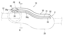
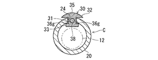
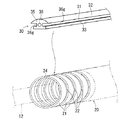
以下、第1実施形態に係るワイヤーハーネス及び経路維持部材付コルゲートチューブについて説明する。図1はワイヤーハーネス10のうちコルゲートチューブ20の装着部分を示す概略斜視図であり、図2は図1のII−II線概略断面図であり、図3はコルゲートチューブ20に経路維持部材30を取付ける工程を示す説明図である。
{First embodiment}
Hereinafter, the corrugated tube with a wire harness and a path maintaining member according to the first embodiment will be described. 1 is a schematic perspective view showing a mounting portion of the
このワイヤーハーネス10は、ワイヤーハーネス本体部12と、コルゲートチューブ20と、経路維持部材30とを備える。
The
ワイヤーハーネス本体部12は、複数の電線が結束された構成とされている。より具体的には、ワイヤーハーネス本体部12は、複数の電線が配設対象となる車両への配線形態に応じて分岐しつつ結束された構成とされている。ワイヤーハーネス本体部12は、必ずしも分岐している必要はないし、また、単一の電線によって構成されていてもよい。また、ワイヤーハーネス本体部12に、他の光ケーブル等が結束されていてもよい。
The wire harness
上記ワイヤーハーネス本体部12を、車両等に配設する際、ワイヤーハーネス本体部12はその配設形態に沿って曲げられる。ワイヤーハーネス本体部12が周辺部分に干渉すること等を抑制するため、ワイヤーハーネス本体部12はその配線形態に沿って曲げられた形状に維持されることがある。このような場合に、本経路維持部材付コルゲートチューブCがワイヤーハーネス本体部12に装着され、当該ワイヤーハーネス本体部12を一定の曲げ形状に維持する。なお、ワイヤーハーネス本体部12に対して本経路維持部材付コルゲートチューブCが装着される部分は、ワイヤーハーネス本体部12の少なくとも一部であればよく、ワイヤーハーネス本体部12の一部であっても、ほぼ全体であってもよい。
When the wire harness
コルゲートチューブ20は、長手方向に沿って環状凸部21と環状凹部22とが交互に形成された筒状部材であり(図3参照)、樹脂等で形成されている。かかるコルゲートチューブ20は、環状凸部21と環状凹部22との間の段部等で容易に弾性変形するため、それ自体では全体として曲げ変形容易な性質を有している。通常、コルゲートチューブ20としては、装着対象となるワイヤーハーネス本体部12の部分の外径よりも大きい(通常は多少大きい程度)内径を有するものが用いられる。
The
また、コルゲートチューブ20の一側部にその長手方向に沿ってスリット24が形成されている。そして、当該スリット24で割開くようにして、ワイヤーハーネス本体部12をコルゲートチューブ20内に容易に配設できるようになっている。
Further, a
経路維持部材30は、塑性変形可能な長尺部材に形成され、コルゲートチューブ20のうちスリット24が形成された部分に取付け可能に構成されている。
The
より具体的には、経路維持部材30は、弾性装着部35と、形状維持線38とを備えている。
More specifically, the
弾性装着部35は、コルゲートチューブ20のうちスリット24が形成された部分に取付装着可能な形状に形成されている。より具体的には、弾性装着部35は、ゴム等のエラストマーによって金型成形された部品である。本実施形態では、弾性装着部35は、コルゲートチューブ20のうちスリット24が形成された部分に取付けるため、次の形状に形成されている。
The
すなわち、弾性装着部35は、コルゲートチューブ20のうちスリット24の両側の端縁部を収容可能な一対の凹溝部36gが形成された部分を有している。換言すれば、経路維持部材30は、長尺状の連結部31の一方側(外周側)縁部に外周側突起部32が配設されると共に、連結部31の他方側(内周側)縁部に内周側突起部33が配設された構成とされ、その長手方向に対して直交する面における断面形状が略H字状を呈している。上記外周側突起部32の外側面は、コルゲートチューブ20の外周面に沿った弧状曲面を呈している。凹溝部36gの幅寸法は、コルゲートチューブ20の厚み寸法(より具体的には、コルゲートチューブ20の径方向において環状凸部21の最外周部分と環状凹部22の最内周部分との差)と略同じかそれよりも大きい(僅かに大きい)程度の寸法に設定されている。凹溝部36gの深さ寸法は、コルゲートチューブ20の端縁部をその径方向に位置決めした状態で収容できる程度であればよく、特に限定はない。
In other words, the
上記経路維持部材30のうち上記一対の凹溝部36gが形成された部分は、経路維持部材30の長手方向全体であってもよいし、その長手方向に沿った一部であってもよい。本実施形態では、一対の凹溝部36gが経路維持部材30の長手方向全体に亘って形成された例で説明する。
The part of the
形状維持線38は、上記弾性装着部35に埋設されている。形状維持線38は、塑性変形可能で、かつ、塑性変形後にワイヤーハーネス本体部12及びコルゲートチューブ20を一定の経路に沿った形状に維持する部材に形成されている。形状維持線38としては、鉄線、銅線、ステンレス線、或はこれらの合金線等の金属線、或は、塑性変形後にある程度の剛性を呈する樹脂等を用いることができる。形状維持線38は、少なくとも1本あればよく、本実施形態では、弾性装着部35に1本の形状維持線38が埋設されている。
The
形状維持線38は、上記弾性装着部35を金型成形する際に、インサート物として埋設されたものであってもよいし、弾性装着部35を形成した後に弾性装着部35に形成された孔又は凹部に嵌め込まれたものであってもよい。ここでは、形状維持線38は、弾性装着部35を金型成形する際に、連結部31内にインサート物としてインサートされている。形状維持線38は、外周側突起部32或は内周側突起部33に埋設されていてもよいし、また、外周の一部が弾性装着部35から露出していてもよい。
The
上記経路維持部材30は、コルゲートチューブ20にその長手方向に沿って取付けられる。ここでは、経路維持部材30は、次のようにして、スリット24に配設した状態で、コルゲートチューブ20に取付けられる。
The
すなわち、コルゲートチューブ20を前記スリット24で開くことで、コルゲートチューブ20内にワイヤーハーネス本体部12を収容する。この状態で、コルゲートチューブ20をスリット24で開いて、コルゲートチューブ20のうちスリット24の両側の端縁部を一対の凹溝部36g内に嵌め込む。この状態では、連結部31がスリット24内に配設され、外周側突起部32がスリット24の外側でコルゲートチューブ20の外周面に沿って配設され、内周側突起部33がスリット24の内側でコルゲートチューブ20内周面に沿って配設される。この後、必要に応じて、タイバンド、粘着テープ等がコルゲートチューブ20の外周に巻付けられ、コルゲートチューブ20の閉状態が維持されると共に、コルゲートチューブ20と経路維持部材30との一体化状態が維持される。なお、上記の他、コルゲートチューブ20自体に設けられたロック構造等によってコルゲートチューブ20の閉状態が維持されてもよい。
That is, the wire harness
この後、経路維持部材30を、コルゲートチューブ20及びその内部のワイヤーハーネス本体部12と共に曲げる。この際の曲げ形状は、ワイヤーハーネス本体部12のうちコルゲートチューブ20が装着される部分の敷設経路に応じた形状である。これにより、ワイヤーハーネス本体部12は、経路維持部材30によって所定の敷設経路に沿った曲げ形状に維持される。
Then, the path |
なお、経路維持部材30の曲げ変形は、経路維持部材30をコルゲートチューブ20に取付ける前に行われてもよいし、或は、ワイヤーハーネス本体部12を敷設する際に行われてもよい。
The bending deformation of the
このように構成された経路維持部材付コルゲートチューブC及びワイヤーハーネス10によると、ワイヤーハーネス本体部12はコルゲートチューブ20によって覆われて保護されると共に、経路維持部材30によって所定の形状に曲った経路を描くように維持されている。このため、経路維持部材30をワイヤーハーネス本体部12の敷設箇所に合わせた形状に曲げることで、ワイヤーハーネス本体部12を当該敷設箇所に合わせた一定の経路に維持できる。経路維持部材30自体は、多様な経路に応じて曲げられるため、多様な経路に応じた曲げ形状の維持が可能となる。このため、より低コストでワイヤーハーネス本体部12を覆いつつその経路を一定に維持できる。特に、ワイヤーハーネス本体部12が3次元的に曲げられた状態で敷設される場合には、その経路規制用の部材が複雑な形状となるため、本実施形態はそのような場合に有効である。
According to the corrugated tube C with the path maintaining member and the
また、ワイヤーハーネス本体部12を曲げた状態に維持できる結果、当該ワイヤーハーネス本体部12を車両等に組付ける際に、車両に対する取付箇所を少なくすることができる。換言すれば、経路維持部材付コルゲートチューブCの取付箇所が少なくとも、ワイヤーハーネス本体部12を一定の曲げ形状に維持できる。このため、ワイヤーハーネス本体部12を取付固定するためのクランプ部材等の使用個数、取付作業を少なくすることができ、この観点からも、経路維持部材付コルゲートチューブCの製造コスト、取付作業コストの低減を図ることができる。
In addition, as a result of maintaining the wire harness
また、経路維持部材30をスリット24に配設した状態で、コルゲートチューブ20に取付けているため、コルゲートチューブ20と経路維持部材30との取付位置関係が安定化する。このため、コルゲートチューブ20を、経路維持部材30の形状に沿った所期の形状に維持し易い。
In addition, since the
弾性装着部35内に形状維持線38を埋設した構成としているため、弾性装着部35によってコルゲートチューブ20へ取付けるための形状を実現し、形状維持線38によって曲げ形状を維持するための性能を得ることができる。
Since the
また、コルゲートチューブ20のうちスリット24の両側の端縁部が一対の凹溝部36gにそれぞれ収容されているため、経路維持部材30がコルゲートチューブ20から外れることが抑制される。
Further, since the edge portions on both sides of the
また、スリット24は経路維持部材30によって閉塞されているため、コルゲートチューブ20内のワイヤーハーネス本体部12がスリット24から外部に脱してしまうといった事態が抑制される。
Moreover, since the
また、弾性装着部35はゴム等のエラストマーによって形成されているため、コルゲートチューブ20内のワイヤーハーネス本体部12と経路維持部材30との磨耗を低減させることができる。
Further, since the elastic mounting
{第2実施形態}
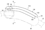
第2実施形態に係るワイヤーハーネス及び経路維持部材付コルゲートチューブについて説明する。図4はワイヤーハーネス110のうちコルゲートチューブ20の装着部分を示す概略斜視図であり、図5は図1のV−V線概略断面図である。なお、本実施の形態の説明において、第1実施形態で説明したものと同様構成要素については同一符号を付してその説明を省略する。
{Second Embodiment}
A wire harness and a corrugated tube with a path maintaining member according to a second embodiment will be described. 4 is a schematic perspective view showing a mounting portion of the
このワイヤーハーネス110は、ワイヤーハーネス本体部12と、コルゲートチューブ20と、経路維持部材130とを備える。
The
ワイヤーハーネス本体部12及びコルゲートチューブ20は、上記実施形態で説明したものと同じである。
The wire harness
経路維持部材130は、塑性変形可能な長尺部材に形成され、コルゲートチューブ20のうちスリット24が形成された部分に取付け可能に構成されている。
The
より具体的には、経路維持部材130は、弾性装着部135と、形状維持線38とを備えている。
More specifically, the
弾性装着部135は、コルゲートチューブ20のうちスリット24が形成された部分に取付装着可能な形状に形成されている。より具体的には、弾性装着部135は、ゴム等のエラストマーによって金型成形された部品である。本実施形態では、弾性装着部135は、コルゲートチューブ20のうちスリット24が形成された部分に取付けるため、次の形状に形成されている。
The
すなわち、経路維持部材130は、蓋部132と突条部134とを有しており、その長手方向に対して直交する面における断面形状が略H字状を呈している。より具体的には、蓋部132は、コルゲートチューブ20のうちスリット24の外側部分を覆う長尺板形状に形成されている。蓋部132の外側面は、コルゲートチューブ20の外周面に沿った弧状曲面を呈している。突条部134は、蓋部132の幅方向中央部に突出された突条形状に形成されている。突条部134の先端部には、その幅方向に突出する部材は設けられていない。突条部134の先端部はその先端側に向けて徐々に細くなる形状に形成されていてもよい。突条部134の突出寸法は、コルゲートチューブ20の厚み寸法(より具体的には、コルゲートチューブ20の径方向において環状凸部21の最外周部分と環状凹部22の最内周部分との差)と略同じかそれよりも大きい(僅かに大きい)程度の寸法に設定されている。もっとも、突条部134の突出寸法は、コルゲートチューブ20の厚み寸法より小さくてもよい。
That is, the
上記経路維持部材130のうち蓋部132と突条部134と有する部分は、経路維持部材130の長手方向全体であってもよいし、その長手方向に沿った一部であってもよい。本実施形態では、蓋部132と突条部134と有する部分が経路維持部材130の長手方向全体亘って形成された例で説明する。
The part which has the
形状維持線38は、上記第1実施形態で説明したものと同様の部材であり、上記弾性装着部135に埋設されている。ここでは、形状維持線38は、弾性装着部135の突条部134に埋設されている。形状維持線38は、上記第1実施形態で述べたのと同様に、弾性装着部135を金型成形する際にインサート物として当該弾性装着部135にインサートされたものであってもよいし、弾性装着部135を金型成形した後に当該弾性装着部135に嵌め込まれたものであってもよい。また、形状維持線38は、蓋部132に埋設されていてもよいし、また、外周の一部が弾性装着部135から露出していてもよい。
The
上記経路維持部材130は、コルゲートチューブ20にその長手方向に沿って取付けられる。ここでは、経路維持部材130は、次のようにして、スリット24に配設した状態で、コルゲートチューブ20に取付けられる。
The
すなわち、コルゲートチューブ20を前記スリット24で開くことで、コルゲートチューブ20内にワイヤーハーネス本体部12を収容する。この状態で、コルゲートチューブ20をスリット24で開いて、経路維持部材130の突条部134をスリット24内に嵌め込む。すると、突条部134がスリット24内に配設されると共に、蓋部132がスリット24の外側でコルゲートチューブ20の外周面に沿って配設されるようになる。
That is, the wire harness
この後、必要に応じて、タイバンド、粘着テープ等がコルゲートチューブ20の外周に巻付けられ、コルゲートチューブ20の閉状態が維持されると共に、コルゲートチューブ20と経路維持部材130との一体化状態が維持される。なお、上記の他、コルゲートチューブ20自体に設けられたロック構造等によってコルゲートチューブ20の閉状態が維持されてもよい。
Thereafter, if necessary, a tie band, an adhesive tape, or the like is wound around the outer periphery of the
この後、経路維持部材130を、コルゲートチューブ20及びその内部のワイヤーハーネス本体部12と共に曲げる。この際の曲げ形状は、ワイヤーハーネス本体部12のうちコルゲートチューブ20が装着される部分の敷設経路に応じた形状である。これにより、ワイヤーハーネス本体部12は、経路維持部材130によって所定の敷設経路に沿った曲げ形状に維持される。
Thereafter, the
なお、経路維持部材130の曲げ変形は、経路維持部材130をコルゲートチューブ20に取付ける前に行われてもよいし、或は、ワイヤーハーネス本体部12を敷設する際に行われてもよい。
The bending deformation of the
このように構成された経路維持部材付コルゲートチューブC2及びワイヤーハーネス110によると、上記第1実施形態で述べたのと同様の理由によって、より低コストでワイヤーハーネス本体部12を覆いつつその経路を一定に維持できる。特に、ワイヤーハーネス本体部12が3次元的に曲げられた状態で敷設される場合には、その経路規制用の部材が複雑な形状となるため、本実施形態はそのような場合に有効である。
According to the corrugated tube C2 with the path maintaining member and the
また、ワイヤーハーネス本体部12を曲げた状態に維持できる結果、当該ワイヤーハーネス本体部12を車両等に組付ける際に、車両に対する取付箇所を少なくすることができる。換言すれば、経路維持部材付コルゲートチューブC2の取付箇所が少なくとも、ワイヤーハーネス本体部12を一定の曲げ形状に維持できる。このため、ワイヤーハーネス本体部12を取付固定するためのクランプ部材等の使用個数、取付作業を少なくすることができ、この観点からも、経路維持部材付コルゲートチューブC2の製造コスト、取付作業コストの低減を図ることができる。
In addition, as a result of maintaining the wire harness
また、経路維持部材130をスリット24に配設した状態で、コルゲートチューブ20に取付けているため、コルゲートチューブ20と経路維持部材130との取付位置関係が安定化する。このため、コルゲートチューブ20を、経路維持部材130の形状に沿った所期の形状に維持し易い。
In addition, since the
弾性装着部135内に形状維持線38を埋設した構成としているため、弾性装着部135によってコルゲートチューブ20へ取付けるための形状を実現し、形状維持線38によって曲げ形状を維持するための性能を得ることができる。
Since the
また、コルゲートチューブ20の外周側から突条部134をスリット24内に配設して、経路維持部材130をコルゲートチューブ20に装着すればよいため、経路維持部材130の装着作業を容易に行える。
In addition, since the
また、弾性装着部135はゴム等のエラストマーによって形成されているため、コルゲートチューブ20内のワイヤーハーネス本体部12と経路維持部材130との磨耗を低減させることができる。
Further, since the elastic mounting
{変形例}
なお、1つの経路維持部材において、第1実施形態で説明したように、一対の凹溝部36gを有する部分と、第2実施形態で説明したように、蓋部132と突条部134とを有する部分とが混在していてもよい。
{Modifications}
In addition, as described in the first embodiment, one path maintaining member has a portion having a pair of
また、経路維持部材は、塑性変形可能な単一の材料によって形成されていてもよい。 The path maintaining member may be formed of a single material that can be plastically deformed.
また、形状維持線38が、経路維持部材30、130の長手方向全体において存在している必要はなく、経路維持部材30の一部に設けられていてもよい。
Further, the
また、1つのワイヤーハーネス本体部12に対して、上記各実施形態で説明した経路維持部材30、130等が混在して用いられていてもよい。
Moreover, the
上記各実施形態及び各変形例で説明した各構成は、相互に矛盾しない限り適宜組合わせることができる。 Each structure demonstrated by each said embodiment and each modification can be suitably combined unless it mutually contradicts.
以上のようにこの発明は詳細に説明されたが、上記した説明は、すべての局面において、例示であって、この発明がそれに限定されるものではない。例示されていない無数の変形例が、この発明の範囲から外れることなく想定され得るものと解される。 As described above, the present invention has been described in detail. However, the above description is illustrative in all aspects, and the present invention is not limited thereto. It is understood that countless variations that are not illustrated can be envisaged without departing from the scope of the present invention.
10、110 ワイヤーハーネス
12 ワイヤーハーネス本体部
20 コルゲートチューブ
21 環状凸部
22 環状凹部
24 スリット
30、130 経路維持部材
35、135 弾性装着部
36g 凹溝部
38 形状維持線
132 蓋部
134 突条部
C、C2 経路維持部材付コルゲートチューブ
DESCRIPTION OF SYMBOLS 10,110
Claims (4)
塑性変形可能な長尺部材に形成され、前記コルゲートチューブのうち前記スリットが形成された部分に取付けられた経路維持部材と、
を備え、
前記経路維持部材は、前記コルゲートチューブのうち前記スリットが形成された部分に取付け可能な形状に形成された弾性装着部と、前記弾性装着部に埋設された形状維持線とを含む経路維持部材付コルゲートチューブ。 Corrugated tubes in which annular convex portions and annular concave portions are alternately formed along the longitudinal direction, and slits are formed along the longitudinal direction;
A path maintaining member formed in a plastically deformable long member and attached to a portion of the corrugated tube where the slit is formed;
Equipped with a,
The path maintaining member includes a path maintaining member including an elastic mounting portion formed in a shape that can be attached to a portion of the corrugated tube in which the slit is formed, and a shape maintaining line embedded in the elastic mounting portion . Corrugated tube.
前記経路維持部材は、前記コルゲートチューブのうち前記スリットの両側の端縁部が収容される一対の凹溝部が形成された部分を含む、経路維持部材付コルゲートチューブ。 A corrugated tube with a path maintaining member according to claim 1,
The path maintaining member is a corrugated tube with a path maintaining member, including a portion of the corrugated tube in which a pair of concave grooves in which end edges on both sides of the slit are accommodated is formed .
前記経路維持部材は、前記コルゲートチューブのうち前記スリットの外側部分を覆う蓋部と、前記蓋部の幅方向中央部に突出され前記スリット内に配設される突条部とを有する部分を含む、経路維持部材付コルゲートチューブ。 A corrugated tube with a path maintaining member according to claim 1,
The path maintaining member includes a portion of the corrugated tube that includes a lid portion that covers an outer portion of the slit, and a protruding portion that is disposed in the slit and protrudes in the center in the width direction of the lid portion. Corrugated tube with a path maintenance member.
少なくとも1本の電線を有し、前記経路維持部材付コルゲートチューブ内に挿通されたワイヤーハーネス本体部と、 A wire harness body having at least one electric wire, and being inserted into the corrugated tube with a path maintaining member;
を備えるワイヤーハーネス。 Wire harness comprising
Priority Applications (1)
| Application Number | Priority Date | Filing Date | Title |
|---|---|---|---|
| JP2011134792A JP5648592B2 (en) | 2011-06-17 | 2011-06-17 | Corrugated tube with path maintenance member and wire harness |
Applications Claiming Priority (1)
| Application Number | Priority Date | Filing Date | Title |
|---|---|---|---|
| JP2011134792A JP5648592B2 (en) | 2011-06-17 | 2011-06-17 | Corrugated tube with path maintenance member and wire harness |
Publications (2)
| Publication Number | Publication Date |
|---|---|
| JP2013005606A JP2013005606A (en) | 2013-01-07 |
| JP5648592B2 true JP5648592B2 (en) | 2015-01-07 |
Family
ID=47673584
Family Applications (1)
| Application Number | Title | Priority Date | Filing Date |
|---|---|---|---|
| JP2011134792A Expired - Fee Related JP5648592B2 (en) | 2011-06-17 | 2011-06-17 | Corrugated tube with path maintenance member and wire harness |
Country Status (1)
| Country | Link |
|---|---|
| JP (1) | JP5648592B2 (en) |
Families Citing this family (3)
| Publication number | Priority date | Publication date | Assignee | Title |
|---|---|---|---|---|
| JP6070513B2 (en) * | 2013-04-11 | 2017-02-01 | 住友電装株式会社 | Wire harness and bending restriction member |
| JP6262075B2 (en) * | 2014-05-20 | 2018-01-17 | タイガースポリマー株式会社 | Corrugated tube manufacturing method |
| JP6994683B2 (en) * | 2020-07-09 | 2022-01-14 | パナソニックIpマネジメント株式会社 | Resin suction pipe for vacuum cleaner |
Family Cites Families (5)
| Publication number | Priority date | Publication date | Assignee | Title |
|---|---|---|---|---|
| JPS59129333U (en) * | 1983-02-21 | 1984-08-30 | 古河電気工業株式会社 | Synthetic resin flexible conduit |
| JPH0486022U (en) * | 1990-11-29 | 1992-07-27 | ||
| JP2554876Y2 (en) * | 1991-07-19 | 1997-11-19 | 昭和飛行機工業株式会社 | Mounting structure of wiring harness in vehicle |
| JP3228201B2 (en) * | 1997-11-13 | 2001-11-12 | 住友電装株式会社 | Corrugated tube guide clamp |
| JP2002064917A (en) * | 2000-08-21 | 2002-02-28 | Sumitomo Wiring Syst Ltd | Auxiliary member for corrugate tube |
-
2011
- 2011-06-17 JP JP2011134792A patent/JP5648592B2/en not_active Expired - Fee Related
Also Published As
| Publication number | Publication date |
|---|---|
| JP2013005606A (en) | 2013-01-07 |
Similar Documents
| Publication | Publication Date | Title |
|---|---|---|
| JP5772405B2 (en) | Corrugated tube with path maintenance member and wire harness | |
| JP5668617B2 (en) | Corrugated tube with path maintenance member and wire harness | |
| JP5831137B2 (en) | Corrugated tube with path maintenance member and wire harness | |
| JP2013046505A (en) | Clamp with belt and wire harness | |
| JP5668613B2 (en) | Corrugated tube with path maintenance member and wire harness | |
| US9525278B2 (en) | Electrical-wire-protecting member using tying member | |
| JP2014207836A (en) | Protector and wiring harness | |
| JP5648592B2 (en) | Corrugated tube with path maintenance member and wire harness | |
| JP2013106485A (en) | Wire harness and path regulation member of the same | |
| JP2015104247A (en) | Wire harness with path maintaining member and manufacturing method of the same | |
| JP2018201284A (en) | Vehicle-body fixing clip and wiring harness | |
| JP2012085442A (en) | Electric wire protector and wiring harness | |
| WO2013065352A1 (en) | Corrugated tube with route-maintaining member and wire harness | |
| WO2013035363A1 (en) | Wire harness and protection member for wire harness | |
| JP2013176205A (en) | Wire harness | |
| JP5772406B2 (en) | Corrugated tube with path maintenance member and wire harness | |
| JP2007185067A (en) | Flexible cable protection tube | |
| JP2012223000A (en) | Wiring harness | |
| JP2013219858A (en) | Corrugated tube with route maintaining member | |
| JP2013055754A (en) | Corrugate tube, assembly method of corrugate tube, and protection structure of wire harness | |
| JP5754400B2 (en) | Path maintenance member and wire harness | |
| JP2013115839A (en) | Corrugate tube with shape maintaining member and wire harness | |
| JP2013102634A (en) | Corrugated tube with path maintaining member, and wire harness |
Legal Events
| Date | Code | Title | Description |
|---|---|---|---|
| A621 | Written request for application examination |
Free format text: JAPANESE INTERMEDIATE CODE: A621 Effective date: 20131129 |
|
| A977 | Report on retrieval |
Free format text: JAPANESE INTERMEDIATE CODE: A971007 Effective date: 20140722 |
|
| A131 | Notification of reasons for refusal |
Free format text: JAPANESE INTERMEDIATE CODE: A131 Effective date: 20140812 |
|
| A521 | Written amendment |
Free format text: JAPANESE INTERMEDIATE CODE: A523 Effective date: 20140926 |
|
| TRDD | Decision of grant or rejection written | ||
| A01 | Written decision to grant a patent or to grant a registration (utility model) |
Free format text: JAPANESE INTERMEDIATE CODE: A01 Effective date: 20141014 |
|
| A61 | First payment of annual fees (during grant procedure) |
Free format text: JAPANESE INTERMEDIATE CODE: A61 Effective date: 20141027 |
|
| R150 | Certificate of patent or registration of utility model |
Ref document number: 5648592 Country of ref document: JP Free format text: JAPANESE INTERMEDIATE CODE: R150 |
|
| LAPS | Cancellation because of no payment of annual fees |