JP2013176205A - Wire harness - Google Patents

Wire harness Download PDF

Info

Publication number
JP2013176205A
JP2013176205A JP2012038772A JP2012038772A JP2013176205A JP 2013176205 A JP2013176205 A JP 2013176205A JP 2012038772 A JP2012038772 A JP 2012038772A JP 2012038772 A JP2012038772 A JP 2012038772A JP 2013176205 A JP2013176205 A JP 2013176205A
Authority
JP
Japan
Prior art keywords
wire harness
connector
main body
path
protective
Prior art date
Legal status (The legal status is an assumption and is not a legal conclusion. Google has not performed a legal analysis and makes no representation as to the accuracy of the status listed.)
Abandoned
Application number
JP2012038772A
Other languages
Japanese (ja)
Inventor
Takahiro Murata
高弘 村田
Hiroyuki Miyashita
広行 宮下
Shinya Kawai
伸哉 河合
Current Assignee (The listed assignees may be inaccurate. Google has not performed a legal analysis and makes no representation or warranty as to the accuracy of the list.)
Sumitomo Wiring Systems Ltd
Original Assignee
Sumitomo Wiring Systems Ltd
Priority date (The priority date is an assumption and is not a legal conclusion. Google has not performed a legal analysis and makes no representation as to the accuracy of the date listed.)
Filing date
Publication date
Application filed by Sumitomo Wiring Systems Ltd filed Critical Sumitomo Wiring Systems Ltd
Priority to JP2012038772A priority Critical patent/JP2013176205A/en
Publication of JP2013176205A publication Critical patent/JP2013176205A/en
Abandoned legal-status Critical Current

Links

Images

Landscapes

  • Insulated Conductors (AREA)
  • Details Of Indoor Wiring (AREA)

Abstract

PROBLEM TO BE SOLVED: To sufficiently protect a portion of a wire harness body part located near a connector while suppressing compression of a space near a section where the connector is disposed.SOLUTION: A wire harness includes: a wire harness body part 12; a route restriction member 30; and a connector 50 connected to at least one electric wire included in the wire harness body part 12. The route restriction member 30 includes: a route restriction body portion 30A disposed along the wire harness body part 12; and a protection end portion 40 extending from an end of the route restriction body portion 30A toward the connector 50.

Description

この発明は、ワイヤーハーネスの経路規制を行うと共にコネクタへの接続部分を保護する技術に関する。   The present invention relates to a technique for regulating a path of a wire harness and protecting a connection portion to a connector.

特許文献1は、電線を可撓性チューブによって覆うことで、電線を保護する技術を開示している。   Patent document 1 is disclosing the technique which protects an electric wire by covering an electric wire with a flexible tube.

特許文献2は、コネクタハウジングに、リヤカバーを取付ける技術を開示している。リヤカバーは、コネクタ本体から引出される電線の引出方向を規制すると共に電線を覆って保護可能に構成されている。   Patent Document 2 discloses a technique for attaching a rear cover to a connector housing. The rear cover is configured to restrict the direction in which the electric wire is drawn out from the connector main body and to protect the electric wire while covering the electric wire.

特開2001−339822号公報JP 2001-339822 A 特開平11−219755号公報JP-A-11-219755

しかしながら、特許文献1では、保護チューブとコネクタとの間に隙間が生じてしまう。このため、ワイヤーハーネスのうちコネクタに近い部分で外傷等に対する保護が不十分となる恐れがある。   However, in Patent Document 1, a gap is generated between the protective tube and the connector. For this reason, there exists a possibility that protection with respect to an injury etc. may become inadequate in the part near a connector among wire harnesses.

特許文献2では、リヤカバーをコネクタハウジングに取付けているため、コネクタの配設箇所周りに、リヤカバーを配設するスペースを確保する必要がある。   In Patent Document 2, since the rear cover is attached to the connector housing, it is necessary to secure a space for arranging the rear cover around the place where the connector is arranged.

そこで、本発明は、コネクタの配設箇所付近でスペースを圧迫することを抑制しつつ、ワイヤーハーネス本体部のうちコネクタに近い部分を十分に保護することを目的とする。   Then, this invention aims at fully protecting the part close | similar to a connector among wire harness main-body parts, suppressing pressing a space in the arrangement | positioning location vicinity of a connector.

上記課題を解決するため、第1の態様に係るワイヤーハーネスは、少なくとも1本の電線を含むワイヤーハーネス本体部と、前記ワイヤーハーネス本体部の少なくとも一部の経路規制を行う経路規制部材と、前記ワイヤーハーネス本体部に含まれる少なくとも1本の電線の端部に接続されたコネクタとを備え、前記経路規制部材が、前記ワイヤーハーネス本体部に沿って配設される経路規制本体部と、前記経路規制本体部の端部から前記コネクタに向けて延出する保護端部とを含む。   In order to solve the above-described problem, a wire harness according to a first aspect includes a wire harness main body portion including at least one electric wire, a route restriction member that restricts at least a portion of the wire harness main body portion, A connector connected to an end of at least one electric wire included in the wire harness main body, and the path control member is disposed along the wire harness main body, and the path A protective end portion extending from the end portion of the restriction main body portion toward the connector.

第2の態様は、第1の態様に係るワイヤーハーネスであって、前記保護端部は、前記コネクタの基端部に重なるように延出している。   A 2nd aspect is a wire harness which concerns on a 1st aspect, Comprising: The said protection edge part is extended so that it may overlap with the base end part of the said connector.

第3の態様は、第2の態様に係るワイヤーハーネスであって、前記保護端部は、前記コネクタの外側を覆うように延出している。   A 3rd aspect is a wire harness which concerns on a 2nd aspect, Comprising: The said protection edge part is extended so that the outer side of the said connector may be covered.

第4の態様は、第3の態様に係るワイヤーハーネスであって、前記保護端部のうち前記コネクタを向く面に、前記コネクタの外周部に接触可能な突起部が形成されている。   A 4th aspect is a wire harness which concerns on a 3rd aspect, Comprising: The protrusion part which can contact the outer peripheral part of the said connector is formed in the surface which faces the said connector among the said protection edge parts.

第5の態様は、第3又は第4の態様に係るワイヤーハーネスであって、長手方向に沿ってスリットが形成され、前記ワイヤーハーネス本体部の少なくとも一部を覆うコルゲートチューブをさらに備え、前記経路規制本体部は、前記スリット内に配設される連結部と、前記連結部の一方の縁部に配設され、前記スリットの両側の端縁部の外側部分を覆う外側突起部と、前記連結部の他方の縁部に配設され、前記スリットの両側の端縁部の内側部分を覆う内側突起部とを含み、前記保護端部は、前記外側突起部の端部に延設されている。   A 5th aspect is a wire harness which concerns on a 3rd or 4th aspect, Comprising: A slit is formed along a longitudinal direction, The corrugated tube which covers at least one part of the said wire harness main-body part is further provided, The said path | route The restricting main body is provided with a connecting portion disposed in the slit, an outer protrusion disposed on one edge of the connecting portion and covering outer portions of end edges on both sides of the slit, and the connecting An inner protrusion that is disposed on the other edge of the slit and covers an inner portion of the edge on both sides of the slit, and the protective end extends to the end of the outer protrusion. .

第6の態様は、第3〜第5のいずれか1つの態様に係るワイヤーハーネスであって、前記保護端部は、前記コネクタに接続される少なくとも1本の電線の外径よりも大きい幅に形成されている。   A 6th aspect is a wire harness which concerns on any one aspect of the 3rd-5th, Comprising: The said protection edge part is a width | variety larger than the outer diameter of the at least 1 electric wire connected to the said connector. Is formed.

第7の態様は、第2の態様に係るワイヤーハーネスであって、前記保護端部は、前記コネクタキャビティ内に挿入されるように延出している。   A 7th aspect is a wire harness which concerns on a 2nd aspect, Comprising: The said protection edge part is extended so that it may insert in the said connector cavity.

第8の態様は、第1〜第7のいずれか1つの態様に係るワイヤーハーネスであって、前記コネクタは、車両のグリル内側に組込まれる部品に接続され、前記保護端部は、前記コネクタに接続される少なくとも1本の電線に対して前記車両の前方側に設けられている。   An eighth aspect is a wire harness according to any one of the first to seventh aspects, wherein the connector is connected to a part incorporated inside a grill of a vehicle, and the protective end is connected to the connector. It is provided on the front side of the vehicle with respect to at least one electric wire to be connected.

第1の態様に係るワイヤーハーネスによると、保護端部によってワイヤーハーネス本体部のうちコネクタに近い部分を十分に保護することができる。また、保護端部は、経路規制本体部の端部から延出するように形成されているため、コネクタの外部にその取付構造を形成する必要はなく、従って、コネクタの配設箇所付近でスペースを圧迫することを抑制することができる。   According to the wire harness which concerns on a 1st aspect, the part near a connector among wire harness main-body parts can fully be protected by a protection edge part. Further, since the protective end portion is formed so as to extend from the end portion of the path regulation main body portion, it is not necessary to form the mounting structure outside the connector, and therefore, there is a space near the location of the connector. Can be suppressed.

第2の態様によると、ワイヤーハーネスのうちコネクタに近い部分をより十分に保護することができる。   According to the 2nd aspect, the part near a connector among wire harnesses can be protected more fully.

第3の態様によると、保護端部をコネクタの外側に配設すればよいため、ワイヤーハーネス本体部に対する経路規制部材の組付作業が容易である。   According to the 3rd aspect, since the protection edge part should just be arrange | positioned on the outer side of a connector, the assembly | attachment operation | work of the path | route control member with respect to a wire harness main-body part is easy.

第4の態様によると、保護端部とコネクタとを挟むように持つと、突起部がコネクタに接触してそれらの位置関係が一定に保たれる。このため、コネクタと当該コネクタに接続された電線との間に過大な負荷が加わることを抑制した状態で、当該コネクタの接続作業を容易に行える。   According to the 4th aspect, when it has so that a protection edge part and a connector may be pinched | interposed, a projection part contacts a connector and those positional relationships are kept constant. For this reason, the connection work of the said connector can be performed easily in the state which suppressed applying excessive load between a connector and the electric wire connected to the said connector.

第5の態様によると、両側突起部より延出された保護端部によって、コネクタの外周を広く覆うことができる。   According to the 5th aspect, the outer periphery of a connector can be widely covered with the protection edge part extended from the both-sides protrusion part.

第6の態様によると、コネクタに接続される電線をより十分に保護できる。   According to the 6th aspect, the electric wire connected to a connector can be protected more fully.

第7の態様によると、保護端部は、コネクタに接続される電線近くで当該電線をより確実に保護できる。   According to the 7th aspect, the protection edge part can protect the said electric wire more reliably near the electric wire connected to a connector.

第8の態様によると、コネクタが、車両のグリル内側に組込まれる部品に接続される場合、車両前方より異物等が飛来し易い。そこで、前記保護端部は、前記コネクタに接続される少なくとも1本の電線に対して前記車両の前方側に設けられていると、車両前方より飛来した異物から電線を十分に保護できる。   According to the 8th aspect, when a connector is connected to the components built in the inside of a grill of a vehicle, a foreign substance etc. tends to fly from the front of a vehicle. Therefore, when the protective end portion is provided on the front side of the vehicle with respect to at least one electric wire connected to the connector, the electric wire can be sufficiently protected from foreign matters flying from the front of the vehicle.

第1実施形態に係るワイヤーハーネスを示す概略斜視図である。It is a schematic perspective view which shows the wire harness which concerns on 1st Embodiment. 図1のII−II線概略断面図である。FIG. 2 is a schematic sectional view taken along line II-II in FIG. 1. ワイヤーハーネスの端部の概略斜視図である。It is a schematic perspective view of the edge part of a wire harness. ワイヤーハーネスの端部の概略側面図である。It is a schematic side view of the edge part of a wire harness. ワイヤーハーネスの配設例を示す説明図である。It is explanatory drawing which shows the example of arrangement | positioning of a wire harness. ワイヤーハーネスの配設例を示す説明図である。It is explanatory drawing which shows the example of arrangement | positioning of a wire harness. 第2実施形態に係るワイヤーハーネスを示す概略平面図である。It is a schematic plan view which shows the wire harness which concerns on 2nd Embodiment. 図7のVIII−VIII線概略断面図である。FIG. 8 is a schematic sectional view taken along line VIII-VIII in FIG. 7. 経路規制部材の端部を示す概略斜視図である。It is a schematic perspective view which shows the edge part of a path | route control member. 保護端部をコネクタに装着した状態を示す説明図である。It is explanatory drawing which shows the state which attached the protection edge part to the connector. 保護端部をコネクタに装着した状態を示す説明図である。It is explanatory drawing which shows the state which attached the protection edge part to the connector.

{第1実施形態}
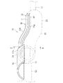
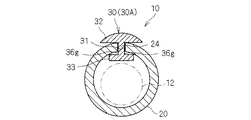
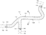
以下、第1実施形態に係るワイヤーハーネスについて説明する。図1は第1実施形態に係るワイヤーハーネス10を示す概略斜視図であり、図2は図1のII−II線概略断面図であり、図3はワイヤーハーネス10の端部の概略斜視図であり、図4はワイヤーハーネス10の端部の概略側面図である。
{First embodiment}
Hereinafter, the wire harness according to the first embodiment will be described. 1 is a schematic perspective view showing the wire harness 10 according to the first embodiment, FIG. 2 is a schematic cross-sectional view taken along line II-II in FIG. 1, and FIG. 3 is a schematic perspective view of an end portion of the wire harness 10. FIG. 4 is a schematic side view of the end portion of the wire harness 10.

このワイヤーハーネス10は、ワイヤーハーネス本体部12と、コルゲートチューブ20と、経路規制部材30と、コネクタ50とを備える。   The wire harness 10 includes a wire harness main body 12, a corrugated tube 20, a path regulating member 30, and a connector 50.

ワイヤーハーネス本体部12は、複数の電線が結束された構成とされている。ワイヤーハーネス本体部12は、複数の電線が配設対象となる車両への配線形態に応じて分岐しつつ結束された構成であってもよいし、分岐していなくてもよい。また、ワイヤーハーネス本体部12は、単一の電線によって構成されていてもよい。また、ワイヤーハーネス本体部12には、他の光ケーブル等が結束されていてもよい。   The wire harness main body 12 is configured by binding a plurality of electric wires. The wire harness main body 12 may have a configuration in which a plurality of electric wires are bundled while branching according to a wiring form to a vehicle to be arranged, or may not be branched. Moreover, the wire harness main-body part 12 may be comprised with the single electric wire. In addition, another optical cable or the like may be bound to the wire harness main body 12.

ワイヤーハーネス本体部12を車両等に配設する際、ワイヤーハーネス本体部12は所定の配設形態に沿って配設される。この際、ワイヤーハーネス本体部12は、これが周辺部分に干渉すること等を抑制するため、所定の配設形態に沿うような形状に維持されることがある。この実施の形態においては、ワイヤーハーネス本体部12に、コルゲートチューブ20及び経路規制部材30を装着することによって、ワイヤーハーネス本体部12が所定経路に沿った形状に維持されると共に、周囲に存在する物体との接触により破損等しないように保護される。なお、ワイヤーハーネス本体部12のうち、どの部分にコルゲートチューブ20及び経路規制部材30を装着するかは、例えば、ワイヤーハーネス本体部12の配索形態、ワイヤーハーネス本体部12が配索される場所の環境等に応じて、決定される。   When the wire harness body 12 is disposed in a vehicle or the like, the wire harness body 12 is disposed along a predetermined arrangement form. At this time, the wire harness main body 12 may be maintained in a shape that conforms to a predetermined arrangement form in order to prevent the wire harness main body 12 from interfering with a peripheral portion. In this embodiment, by attaching the corrugated tube 20 and the path regulating member 30 to the wire harness main body 12, the wire harness main body 12 is maintained in a shape along a predetermined path and is present in the periphery. It is protected from damage due to contact with objects. In addition, it is a place where the corrugated tube 20 and the path | route control member 30 are mounted | worn to which part among the wire harness main-body parts 12, the wiring form of the wire harness main-body part 12, the wire harness main-body part 12 is routed, for example It is determined according to the environment of the.

ここでは、コルゲートチューブ20及び経路規制部材30は、ワイヤーハーネス本体部12の少なくとも1つの端部を含む部分に装着される。   Here, the corrugated tube 20 and the path regulating member 30 are attached to a portion including at least one end of the wire harness main body 12.

コルゲートチューブ20は、長手方向に沿って環状凸部と環状凹部とが交互に形成された筒状部材であり(図4参照)、樹脂等で形成されている。コルゲートチューブ20は、環状凸部と環状凹部との間の段部等で、容易に弾性変形するため、それ自体では、全体として、曲げ変形容易な性質を有している。   The corrugated tube 20 is a cylindrical member in which annular convex portions and annular concave portions are alternately formed along the longitudinal direction (see FIG. 4), and is formed of a resin or the like. Since the corrugated tube 20 is easily elastically deformed at a step portion between the annular convex portion and the annular concave portion, the corrugated tube 20 as a whole has a property of being easily bent and deformed.

コルゲートチューブ20の一側部には、コルゲートチューブ20の長手方向に沿って、スリット24が形成されている。コルゲートチューブ20を、このスリット24で割開くようにして、ワイヤーハーネス本体部12をコルゲートチューブ20内に容易に配設できるようになっている。   A slit 24 is formed on one side of the corrugated tube 20 along the longitudinal direction of the corrugated tube 20. The wire harness main body 12 can be easily disposed in the corrugated tube 20 by splitting the corrugated tube 20 with the slit 24.

経路規制部材30は、長手方向に沿って一定形状を維持するように金型成型された長尺部材であり、P.P.(ポリプロピレン)等の樹脂によって形成されている。換言すれば、経路規制部材30は、金型成型時点で、一定形状に形成されている。もっとも、経路規制部材30は、外力によって曲げ可能で、かつ、曲げられた後、所定形状に維持できる構成、例えば、ゴム等の弾性材料内に針金等の塑性変形可能な線材を配設した構成等であってもよい。この経路規制部材30がワイヤーハーネス本体部12に装着されることで、当該ワイヤーハーネス本体部12が所定の形状に維持される。   The path regulating member 30 is a long member that is molded so as to maintain a certain shape along the longitudinal direction. P. It is made of a resin such as (polypropylene). In other words, the path regulating member 30 is formed in a fixed shape at the time of mold molding. However, the path regulating member 30 can be bent by an external force and can be maintained in a predetermined shape after being bent, for example, a structure in which a plastically deformable wire such as a wire is disposed in an elastic material such as rubber. Etc. By attaching the path regulating member 30 to the wire harness main body 12, the wire harness main body 12 is maintained in a predetermined shape.

コネクタ50は、上記ワイヤーハーネス本体部12に含まれる少なくとも1本の電線13の端部に接続されている。ここでは、ワイヤーハーネス本体部12の端部に1本の電線13が延出しており、当該電線13にコネクタ50が接続されている。コネクタに接続される電線は複数であってもよい。   The connector 50 is connected to the end of at least one electric wire 13 included in the wire harness main body 12. Here, one electric wire 13 extends to the end of the wire harness main body 12, and the connector 50 is connected to the electric wire 13. There may be a plurality of electric wires connected to the connector.

経路規制部材30は、経路規制本体部30Aと、保護端部40とを備える。   The path regulating member 30 includes a path regulating main body 30A and a protective end 40.

経路規制本体部30Aは、ワイヤーハーネス本体部12に沿って配設され、当該ワイヤーハーネス本体部12の経路規制を行う部分である。より具体的には、経路規制本体部30Aは、直線状又は少なくとも一部が曲げられた形状に形成されている。ここでは、経路規制本体部30Aは、ワイヤーハーネス本体部12のうち装着対象となる部分が配設される配設経路に応じた曲げ形状に設定されている。図1に示す例では、経路規制本体部30Aの長手方向の中間部がなだらかなS字を描くように曲っており、経路規制本体部30Aの両端部が直線状に形成されている。経路規制本体部30Aのうち曲げた形状に形成される部分は、その全体であっても一部であってもよい。   The path regulation main body 30 </ b> A is a part that is disposed along the wire harness main body 12 and regulates the path of the wire harness main body 12. More specifically, the path regulation main body 30A is formed in a linear shape or a shape in which at least a part thereof is bent. Here, the path regulation main body 30A is set in a bent shape according to the arrangement path in which the portion to be mounted of the wire harness main body 12 is disposed. In the example shown in FIG. 1, the middle part in the longitudinal direction of the path regulation main body 30A is bent so as to draw a gentle S-shape, and both end parts of the path regulation main body 30A are formed in a straight line. The part formed in a bent shape in the path regulation main body 30A may be the whole or a part thereof.

上記経路規制本体部30Aは、コルゲートチューブ20のスリット24に装着される。すなわち、経路規制本体部30Aは、コルゲートチューブ20のうちスリット24の両側の端縁部を収容可能な一対の凹溝部36gが形成された部分を有している。換言すれば、経路規制本体部30Aは、スリット24内に配設される連結部31と、連結部31の一方の縁部に配設され、スリット24の両側の端縁部の外側部分を覆う外側突起部32と、連結部31の他方の縁部に配設され、スリット24の両側の端縁部の内側部分を覆う内側突起部33とを備える。外側突起部32及び内側突起部33は、連結部31の両側に突出している。経路規制本体部30Aの長手方向に対して直交する面における、経路規制本体部30Aの断面形状は略H字状を呈している。連結部31の両側には、外側突起部32と内側突起部33とで挟まれる一対の凹溝部36gが形成されている。   The path regulation main body 30 </ b> A is attached to the slit 24 of the corrugated tube 20. That is, the path regulation main body 30 </ b> A has a portion in which a pair of concave grooves 36 g that can accommodate the edge portions on both sides of the slit 24 in the corrugated tube 20 are formed. In other words, the path regulation main body portion 30 </ b> A is disposed at the connection portion 31 disposed in the slit 24 and one edge portion of the connection portion 31 and covers the outer portions of the edge portions on both sides of the slit 24. An outer protrusion 32 and an inner protrusion 33 disposed on the other edge of the connecting portion 31 and covering the inner portions of the end edges on both sides of the slit 24 are provided. The outer protrusion 32 and the inner protrusion 33 protrude on both sides of the connecting portion 31. The cross-sectional shape of the path regulation main body 30A on the surface orthogonal to the longitudinal direction of the path regulation main body 30A is substantially H-shaped. On both sides of the connecting portion 31, a pair of concave groove portions 36 g sandwiched between the outer protruding portion 32 and the inner protruding portion 33 are formed.

凹溝部36gの幅寸法は、コルゲートチューブ20の厚み寸法(より具体的には、コルゲートチューブ20の径方向において環状凸部の最外周部分と環状凹部の最内周部分との差)と略同じかそれよりも大きい(僅かに大きい)程度の寸法に設定されている。凹溝部36gの深さ寸法は、コルゲートチューブ20の端縁部をその径方向に位置決めした状態で収容できる程度であればよく、特に限定はない。   The width dimension of the recessed groove portion 36g is substantially the same as the thickness dimension of the corrugated tube 20 (more specifically, the difference between the outermost peripheral portion of the annular convex portion and the innermost peripheral portion of the annular concave portion in the radial direction of the corrugated tube 20). It is set to a dimension that is larger (or slightly larger) than that. The depth dimension of the groove part 36g should just be a grade which can be accommodated in the state which positioned the edge part of the corrugated tube 20 in the radial direction, and there is no limitation in particular.

また、外側突起部32は、その両側縁部に向けて徐々に薄くなる形状に形成されると共に、その外周部がコルゲートチューブ20の外周形状に沿って外側に凸となるように湾曲する弧状形状に形成されている。   Further, the outer protrusion 32 is formed in a shape that becomes gradually thinner toward both side edges, and an arc shape that curves so that its outer peripheral portion protrudes outward along the outer peripheral shape of the corrugated tube 20. Is formed.

上記経路規制本体部30Aは、次のようにしてスリット24に装着される。すなわち、連結部31の一端部を、スリット24の一端側内に挿入する。そして、経路規制本体部30Aをスリット24の中間部に向けて押込んでいく。すると、連結部31がスリット24内に配設された状態で、外側突起部32がスリット24に沿ってコルゲートチューブ20の外周側に配設されると共に、内側突起部33がスリット24に沿ってコルゲートチューブ20の内周側に配設され、経路規制本体部30Aがコルゲートチューブ20のスリット24に装着されることとなる。なお、スリット24の中間部を割開いて、スリット24内に経路規制本体部30Aを配設してもよい。   The path regulation main body 30A is attached to the slit 24 as follows. That is, one end portion of the connecting portion 31 is inserted into one end side of the slit 24. Then, the path regulation main body 30 </ b> A is pushed toward the intermediate portion of the slit 24. Then, in a state where the connecting portion 31 is disposed in the slit 24, the outer protrusion 32 is disposed on the outer peripheral side of the corrugated tube 20 along the slit 24, and the inner protrusion 33 is aligned along the slit 24. The path regulating main body 30 </ b> A is disposed on the inner peripheral side of the corrugated tube 20 and is attached to the slit 24 of the corrugated tube 20. Note that the middle portion of the slit 24 may be opened, and the path regulation main body 30 </ b> A may be disposed in the slit 24.

ワイヤーハーネス本体部12をコルゲートチューブ20で覆うと共にこのコルゲートチューブ20のスリット24に経路規制部材30の経路規制本体部30Aを取付けた状態で、コルゲートチューブ20及び経路規制本体部30Aに粘着テープ等が巻回されることで、コルゲートチューブ20と経路規制本体部30Aとの一体化状態が維持される。また、コルゲートチューブ20と当該コルゲートチューブ20の端部から延出するワイヤーハーネス本体部12(特に、コネクタ50の反対側に延出する部分)とに粘着テープ等を巻回することで、ワイヤーハーネス本体部12に対するコルゲートチューブ20の位置決めが図られる。   With the wire harness body 12 covered with the corrugated tube 20 and the path regulating body 30A of the path regulating member 30 attached to the slit 24 of the corrugated tube 20, an adhesive tape or the like is attached to the corrugated tube 20 and the path regulating body 30A. By being wound, the integrated state of the corrugated tube 20 and the path regulation main body 30A is maintained. Further, by winding an adhesive tape or the like around the corrugated tube 20 and the wire harness main body 12 (particularly, the portion extending to the opposite side of the connector 50) extending from the end of the corrugated tube 20, the wire harness The corrugated tube 20 is positioned with respect to the main body portion 12.

保護端部40は、経路規制本体部30Aの端部からコネクタ50に向けて延出するように形成されている。ここでは、保護端部40は、コネクタ50の外側を覆いつつ、当該コネクタ50の基端部(電線13が接続される側の端部)と重なるように延出している。   The protective end portion 40 is formed so as to extend from the end portion of the path regulation main body portion 30 </ b> A toward the connector 50. Here, the protective end 40 extends outside the connector 50 so as to overlap the base end of the connector 50 (the end on the side to which the electric wire 13 is connected).

より具体的には、保護端部40は、外側突起部32の端部からコネクタ50に向けて延出されている。ここでは、外側突起部32の端部に肉厚部分32aが設けられ、この肉厚部分32aの端部の外周部から保護端部40が延出している。   More specifically, the protective end 40 extends from the end of the outer protrusion 32 toward the connector 50. Here, a thick portion 32a is provided at the end of the outer protrusion 32, and the protective end 40 extends from the outer periphery of the end of the thick portion 32a.

保護端部40は、横方向断面が弧状である板部材に形成されている。保護端部は、その他、半円筒状又は円筒状、平板状、横断面L字状の部材であってもよい。電線13をなるべく十分に保護するためには、保護端部は電線13周りのなるべく多くの部分を覆っていることが好ましい。また、コネクタ50を相手側のコネクタに接続する作業性を考慮すると、保護端部40の一側方が開口していることが好ましい。両者を両立させるためには、保護端部40は、横方向断面が弧状である板部材(半円筒形状を含む)に形成されていることが好ましい。   The protective end portion 40 is formed on a plate member whose cross section in the transverse direction is an arc shape. In addition, the protective end may be a member having a semi-cylindrical shape, a cylindrical shape, a flat plate shape, or an L-shaped cross section. In order to protect the electric wire 13 as much as possible, the protective end portion preferably covers as many portions as possible around the electric wire 13. In consideration of workability for connecting the connector 50 to the mating connector, it is preferable that one side of the protective end 40 is open. In order to make both compatible, it is preferable that the protective end 40 is formed on a plate member (including a semi-cylindrical shape) whose cross section in the transverse direction is an arc shape.

保護端部40の長さ寸法は、上記経路規制本体部30Aがワイヤーハーネス本体部12に固定されるべき予定位置を基準にして、当該経路規制本体部30Aの端部とコネクタ50との間の距離よりも大きく設定されている。これにより、経路規制本体部30Aがワイヤーハーネス本体部12に対して所定位置に固定された状態で、保護端部40の先端部がコネクタ50の少なくとも一部に被さるようになっている。   The length dimension of the protective end 40 is determined between the end of the path regulation main body 30A and the connector 50 with reference to a predetermined position where the path regulation main body 30A is to be fixed to the wire harness main body 12. It is set larger than the distance. Accordingly, the distal end portion of the protective end portion 40 covers at least a part of the connector 50 in a state where the path regulation main body portion 30 </ b> A is fixed at a predetermined position with respect to the wire harness main body portion 12.

また、保護端部40の幅寸法は、特に限定されないが、コネクタ50に接続される少なくとも1本の電線13の外径よりも大きい幅に形成されていることが好ましい。すなわち、コネクタ50に接続される電線13が1本である場合には、保護端部40の幅は当該電線13の外径よりも大きいことが好ましく、コネクタ50に接続される電線13が複数である場合には、保護端部40の幅は複数の電線13の結束形態の外周に接する円の外径よりも大きいことが好ましい。   Further, the width dimension of the protective end portion 40 is not particularly limited, but is preferably formed to have a width larger than the outer diameter of at least one electric wire 13 connected to the connector 50. That is, when the number of the electric wires 13 connected to the connector 50 is one, it is preferable that the width of the protective end portion 40 is larger than the outer diameter of the electric wires 13, and there are a plurality of electric wires 13 connected to the connector 50. In some cases, the width of the protective end portion 40 is preferably larger than the outer diameter of a circle in contact with the outer periphery of the bundled form of the plurality of electric wires 13.

なお、保護端部40は、必ずしも直線状に延出している必要はなく、途中で曲っていてもよい。   In addition, the protection edge part 40 does not necessarily need to extend linearly, and may be bent on the way.

また、上記保護端部40のうちコネクタ50を向く面に、突起部42が形成されている。突起部42の高さ寸法は、コルゲートチューブ20の端部から電線13が真っ直ぐ延出した状態で、コネクタ50の外周部に接触可能な程度に設定されていることが好ましい(図4参照)。これにより、保護端部40とコネクタ50とを重ねるようにして手で挟み持った状態で、コネクタ50が保護端部40側に大きく偏って配設されることが抑制され、電線13に対して無理な力が作用し難くなる。   A protrusion 42 is formed on the surface of the protective end 40 facing the connector 50. The height of the protrusion 42 is preferably set to such an extent that it can contact the outer periphery of the connector 50 in a state in which the electric wire 13 extends straight from the end of the corrugated tube 20 (see FIG. 4). Thereby, in a state where the protective end portion 40 and the connector 50 are sandwiched and held by hand, it is suppressed that the connector 50 is arranged to be largely biased toward the protective end portion 40 side. Unreasonable force becomes difficult to act.

上記ワイヤーハーネス10の使用形態例について説明する。   A usage example of the wire harness 10 will be described.

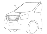
上記ワイヤーハーネス10は、例えば、図5及び図6に示すように、車両60のグリル62の内側に組込まれる部品64への配線材として用いられる。そのような部品64としては、例えば、警笛を発するためのホーン部品64が想定される。   For example, as shown in FIGS. 5 and 6, the wire harness 10 is used as a wiring material to a component 64 incorporated inside a grill 62 of a vehicle 60. As such a component 64, for example, a horn component 64 for emitting a horn is assumed.

この場合、ワイヤーハーネス10の上記コネクタ50は、当該ホーン部品64のコネクタ65にコネクタ接続される。また、ワイヤーハーネス10のコルゲートチューブ20及び経路規制本体部30Aの装着部分は、クランプ部品等で車体に取付固定される。これにより、ワイヤーハーネス10自体は、車両に対して一定位置及び一定姿勢で取付固定される。   In this case, the connector 50 of the wire harness 10 is connected to the connector 65 of the horn component 64. Moreover, the attachment part of the corrugated tube 20 and the path | route control main-body part 30A of the wire harness 10 is attached and fixed to a vehicle body by clamp parts etc. Thereby, the wire harness 10 itself is attached and fixed to the vehicle at a fixed position and a fixed posture.

上記コネクタ50がコネクタ65に接続された状態で、保護端部40は、コネクタ50に接続される電線13に対して車両前方側に設けられていることが好ましい。これにより、車両前方からの飛来物に対して、電線13を有効に保護できる。   In a state where the connector 50 is connected to the connector 65, the protective end 40 is preferably provided on the vehicle front side with respect to the electric wire 13 connected to the connector 50. Thereby, the electric wire 13 can be effectively protected against flying objects from the front of the vehicle.

以上のように構成されたワイヤーハーネス10によると、保護端部40がコネクタ50に向けて延出しているため、当該保護端部40によってワイヤーハーネス本体部12のうちコネクタ50に近い部分を十分に保護できる。また、保護端部40は、経路規制本体部30Aの端部から延出するように形成されているため、コネクタ50の外部にその取付構造を形成する必要はなく、保護端部40の設置スペースを小さくできる。このため、コネクタ50の配設箇所付近のスペースを圧迫することを抑制できる。   According to the wire harness 10 configured as described above, since the protective end portion 40 extends toward the connector 50, the protective end portion 40 sufficiently covers a portion close to the connector 50 in the wire harness main body portion 12. Can protect. Further, since the protective end 40 is formed so as to extend from the end of the path regulation main body 30A, it is not necessary to form the mounting structure outside the connector 50, and the installation space for the protective end 40 is not required. Can be reduced. For this reason, it can suppress pressing the space near the arrangement | positioning location of the connector 50. FIG.

また、保護端部40はコネクタ50と重なっているため、コネクタ50に接続された電線13をより十分に保護できる。   Further, since the protective end 40 overlaps the connector 50, the electric wire 13 connected to the connector 50 can be more sufficiently protected.

また、保護端部40は、コネクタ50の外側に配設されるため、ワイヤーハーネス本体部12を覆うコルゲートチューブ20に経路規制部材30を装着する際に、コネクタ50に対する保護端部40の装着作業等を不要とすることができる。これにより、ワイヤーハーネス本体部12に対する経路規制部材30の組付作業が容易となる。   Further, since the protective end 40 is disposed outside the connector 50, when the path regulating member 30 is mounted on the corrugated tube 20 that covers the wire harness main body 12, the protective end 40 is attached to the connector 50. Etc. can be made unnecessary. Thereby, the assembly | attachment operation | work of the path | route control member 30 with respect to the wire harness main-body part 12 becomes easy.

また、保護端部40のうちコネクタ50に対向する部分に突起部42が形成されているため、保護端部40とコネクタ50とを重ねて挟むように持つと(図6の矢符P参照)、突起部42がコネクタ50に接触して、それらの位置関係が一定に保たれる。特に、コネクタ50は、保護端部40の内周部から離れた位置に保たれる。これにより、コネクタ50と当該コネクタ50に接続された電線13との間に過大な負荷が加わることを抑制しつつ、保護端部40とコネクタ50とを持って、コネクタ50をコネクタ65に接続する作業を容易に行える。   Moreover, since the protrusion part 42 is formed in the part which opposes the connector 50 among the protection end parts 40, when it has so that the protection end part 40 and the connector 50 may be pinched | interposed (refer arrow P of FIG. 6) The protrusions 42 come into contact with the connector 50, and their positional relationship is kept constant. In particular, the connector 50 is kept at a position away from the inner periphery of the protective end 40. Thus, the connector 50 is connected to the connector 65 with the protective end 40 and the connector 50 while suppressing an excessive load from being applied between the connector 50 and the electric wire 13 connected to the connector 50. Work can be done easily.

また、保護端部40は、外側突起部32の端部より延出しているため、電線13から離れた位置の保護端部40によって電線13及びコネクタ50の外周を広く覆うことができる。   Further, since the protective end portion 40 extends from the end portion of the outer protrusion 32, the outer periphery of the electric wire 13 and the connector 50 can be widely covered with the protective end portion 40 at a position away from the electric wire 13.

また、保護端部40は、コネクタ50に接続される電線13の外径よりも幅広に形成されているため、所定方向からの外傷に対して電線13を有効に保護できる。   Moreover, since the protection edge part 40 is formed wider than the outer diameter of the electric wire 13 connected to the connector 50, the electric wire 13 can be effectively protected against an injury from a predetermined direction.

また、コネクタ50がグリル62の内側に組込まれる部品64に接続される場合を想定すると、そのコネクタ50に接続される電線13は、車両前方からの飛来物によって外傷を受ける可能性が高いと考えられる。そこで、保護端部40を、電線13に対して車両前方側に設けると、車両前方からの飛来物が保護端部40に当接して、電線13に対して当り難くなる。このため、飛来物による電線13の外傷を有効に抑制できる。   Further, assuming that the connector 50 is connected to a component 64 incorporated inside the grill 62, the electric wire 13 connected to the connector 50 is considered highly likely to be damaged by flying objects from the front of the vehicle. It is done. Therefore, when the protective end 40 is provided on the vehicle front side with respect to the electric wire 13, a flying object from the front of the vehicle comes into contact with the protective end 40 and is difficult to hit the electric wire 13. For this reason, the damage of the electric wire 13 by a flying object can be suppressed effectively.

さらに、保護端部40は経路規制本体部30Aを介してワイヤーハーネス本体部12に固定されているため、保護端部を途中で曲げる等して、コネクタ50からの保護端部40及び電線13の延在方向を任意に設定できるという利点もある。勿論、ワイヤーハーネス本体部12自体については、経路規制本体部30Aの形状を適宜設定することで、任意の経路形状に設定できる。   Further, since the protective end 40 is fixed to the wire harness main body 12 via the path restriction main body 30A, the protective end 40 and the electric wires 13 from the connector 50 are bent by bending the protective end in the middle. There is also an advantage that the extending direction can be arbitrarily set. Of course, the wire harness body 12 itself can be set to an arbitrary path shape by appropriately setting the shape of the path regulation body 30A.

なお、本実施形態では、コルゲートチューブ20のスリット24に装着される経路規制部材30の端部に保護端部40を設けた例で説明したが、次に説明する実施形態のように、ワイヤーハーネス本体部12に直接装着される経路規制部材の端部に、上記と同様の保護端部が設けられていてもよい。つまり、ワイヤーハーネス本体部112に対して経路規制を行うべく所定位置に取付けられる経路規制部材に、本保護端部を設けることができる。   In the present embodiment, the example in which the protective end 40 is provided at the end of the path regulating member 30 attached to the slit 24 of the corrugated tube 20 has been described. However, as in the embodiment described below, the wire harness A protective end similar to the above may be provided at the end of the path regulating member that is directly attached to the main body 12. In other words, the protection end portion can be provided on a path regulating member that is attached at a predetermined position to regulate the path with respect to the wire harness main body 112.

{第2実施形態}
第2実施形態に係るワイヤーハーネス110について説明する。
{Second Embodiment}
A wire harness 110 according to the second embodiment will be described.

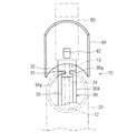
図7は第2実施形態に係るワイヤーハーネス110を示す概略平面図であり、図8は図7のVIII−VIII線概略断面図であり、図9は経路規制部材130の端部を示す概略斜視図であり、図10及び図11は、保護端部140をコネクタ150に装着した状態を示す説明図である。   7 is a schematic plan view showing the wire harness 110 according to the second embodiment, FIG. 8 is a schematic cross-sectional view taken along the line VIII-VIII in FIG. 7, and FIG. 9 is a schematic perspective view showing an end of the path regulating member 130. FIGS. 10 and 11 are explanatory views showing a state in which the protective end 140 is attached to the connector 150. FIG.

ワイヤーハーネス110は、ワイヤーハーネス本体部112と、経路規制部材130と、コネクタ150とを備える。   The wire harness 110 includes a wire harness main body 112, a path regulating member 130, and a connector 150.

ワイヤーハーネス本体部112は、上記第1実施形態と同様に、少なくとも1本の電線により構成される配線材である。ここでは、ワイヤーハーネス本体部112は、途中で分岐する形状に示されており、3つの端部を含んでいる。   The wire harness main body 112 is a wiring member constituted by at least one electric wire, as in the first embodiment. Here, the wire harness main body 112 is shown in a shape that branches in the middle, and includes three ends.

コネクタ150は、上記ワイヤーハーネス本体部112に含まれる少なくとも1本の電線113の端部に接続されている。ここでは、ワイヤーハーネス本体部112の3つの端部のそれぞれに1本の電線113が延出しており、当該電線113にコネクタ150が接続されている。以下では、そのうちの1つの端部に着目して説明する。なお、コネクタに接続される電線は複数であってもよい。   The connector 150 is connected to the end of at least one electric wire 113 included in the wire harness main body 112. Here, one electric wire 113 extends to each of the three ends of the wire harness main body 112, and the connector 150 is connected to the electric wire 113. Below, it demonstrates paying attention to the edge part of one of them. A plurality of electric wires may be connected to the connector.

経路規制部材130は、長手方向に沿って一定形状を維持するように金型成型された長尺部材であり、P.P.(ポリプロピレン)等の樹脂によって形成されている。換言すれば、経路規制部材130は、金型成型時点で、一定形状に形成されている。もっとも、経路規制部材130は、外力によって曲げ可能で、かつ、曲げられた後、所定形状に維持できる構成、例えば、ゴム等の弾性材料内に針金等の塑性変形可能な線材を配設した構成等であってもよい。この経路規制部材130がワイヤーハーネス本体部112に装着されることで、当該ワイヤーハーネス本体部112が所定の形状に維持される。   The path regulating member 130 is a long member that is molded so as to maintain a certain shape along the longitudinal direction. P. It is made of a resin such as (polypropylene). In other words, the path regulating member 130 is formed in a fixed shape at the time of mold molding. However, the path regulating member 130 can be bent by an external force and can be maintained in a predetermined shape after being bent, for example, a structure in which a plastically deformable wire such as a wire is disposed in an elastic material such as rubber. Etc. By attaching the path regulating member 130 to the wire harness main body 112, the wire harness main body 112 is maintained in a predetermined shape.

この経路規制部材130は、ワイヤーハーネス本体部112の少なくとも一部の経路を規制する部材であり、経路規制本体部130Aと、保護端部140とを備える。   This path regulating member 130 is a member that regulates at least a part of the path of the wire harness main body 112, and includes a path regulating main body 130 </ b> A and a protective end 140.

経路規制本体部130Aは、ワイヤーハーネス本体部112の少なくとも1つの端部近傍を含む部分又は全体に装着され、その装着箇所においてワイヤーハーネス本体部112の経路規制を行う。ここでは、経路規制本体部130Aは、ワイヤーハーネス本体部112の分岐形態に応じた分岐形状に形成され、当該ワイヤーハーネス本体部112のほぼ全体の経路規制を行う。   The path regulation main body part 130A is attached to a part including the vicinity of at least one end of the wire harness main body part 112 or the entirety thereof, and performs path regulation of the wire harness main body part 112 at the attachment location. Here, the path regulation main body part 130 </ b> A is formed in a branch shape corresponding to the branching form of the wire harness main body part 112, and performs almost the whole path regulation of the wire harness main body part 112.

また、経路規制本体部130Aは、ワイヤーハーネス本体部112の一部を収容可能な形状、ここでは、経路規制部材130の延在方向に対して略直交する面において、断面円弧状に形成されている。そして、ワイヤーハーネス本体部112を経路規制本体部130A内に部分的に収容するようにしつつ当該経路規制本体部130Aに沿って配設し、この状態で、ワイヤーハーネス本体部112及び経路規制本体部130Aに粘着テープT等を巻回すると、ワイヤーハーネス本体部112と経路規制本体部130Aとが相互に位置決めされた状態で一体化される。   Further, the path regulation main body 130A is formed in a shape that can accommodate a part of the wire harness main body 112, in this case, in a cross-section arc shape on a surface substantially orthogonal to the extending direction of the path regulation member 130. Yes. And it arrange | positions along the said path | route control main-body part 130A, making it partially accommodate in the path | route control main-body part 130A, and in this state, the wire-harness main-body part 112 and a path | route control main-body part When the adhesive tape T or the like is wound around 130A, the wire harness main body 112 and the path regulation main body 130A are integrated with each other positioned.

保護端部140は、上記経路規制本体部130Aの端部からコネクタ150に向けて延出するように形成されている。ここでは、保護端部140は、コネクタ150と重なり、かつ、そのキャビティ153に挿入可能なように延出している。   The protective end 140 is formed so as to extend from the end of the path regulation main body 130 </ b> A toward the connector 150. Here, the protective end portion 140 overlaps with the connector 150 and extends so as to be inserted into the cavity 153.

ここで、コネクタ150の一構成例について説明しておく。コネクタ150は、単芯タイプのものであり、コネクタハウジング部152と、ロック用弾性片154とを備えている。   Here, a configuration example of the connector 150 will be described. The connector 150 is of a single core type, and includes a connector housing portion 152 and an elastic piece 154 for locking.

コネクタハウジング部152は、内部にキャビティ153が形成された筺状に形成されている。キャビティ153は、コネクタハウジング部152の一端部(基端部)及び他端部(先端部)に向けて開口している。キャビティ153の基端部側開口は、その先端部側開口よりも大きい。また、キャビティ153は、電線113の端部に圧着等により固定された端子114を収容可能な大きさ及び形状に形成されている。そして、端子114をキャビティ153の基端側開口よりキャビティ153内に挿入すると、キャビティ153内に形成されたランス部が端子114に係止して、当該端子114がキャビティ153内の一定位置に収容保持される。   The connector housing portion 152 is formed in a bowl shape having a cavity 153 formed therein. The cavity 153 opens toward one end portion (base end portion) and the other end portion (tip end portion) of the connector housing portion 152. The proximal end side opening of the cavity 153 is larger than the distal end side opening thereof. The cavity 153 is formed in a size and shape that can accommodate the terminal 114 fixed to the end of the electric wire 113 by crimping or the like. Then, when the terminal 114 is inserted into the cavity 153 through the opening on the proximal end side of the cavity 153, the lance formed in the cavity 153 is locked to the terminal 114, and the terminal 114 is accommodated at a fixed position in the cavity 153. Retained.

ロック用弾性片154は、上記コネクタハウジング部152の外周りに設けられた弾性片であり、係止突起154aを有している。係止突起154aを相手側コネクタの被係止部に係止させることで、本コネクタ150が相手側のコネクタに接続された状態が維持される。   The locking elastic piece 154 is an elastic piece provided around the outer periphery of the connector housing portion 152, and has a locking projection 154a. By locking the locking protrusion 154a to the locked portion of the mating connector, the state where the connector 150 is connected to the mating connector is maintained.

上記キャビティ153の基端側開口は、端子114の基端部(具体的には電線113への圧着部)よりも大きく、端子114の外周とキャビティ153の内周との間には隙間が設けられる。一例を挙げると、キャビティ153の基端部開口の長寸方向の幅が8mm程度、短寸方向の幅が5mm程度であり、端子114の圧着部の幅が5mm程度、厚みが2mm程度であり、この場合、キャビティ153の基端開口と端子114の圧着部との間に1〜3mm程度の隙間が存在し得る。   The opening on the proximal end side of the cavity 153 is larger than the proximal end portion of the terminal 114 (specifically, the crimping portion to the electric wire 113), and a gap is provided between the outer periphery of the terminal 114 and the inner periphery of the cavity 153. It is done. For example, the width in the long dimension of the base end opening of the cavity 153 is about 8 mm, the width in the short dimension is about 5 mm, the width of the crimping part of the terminal 114 is about 5 mm, and the thickness is about 2 mm. In this case, a gap of about 1 to 3 mm may exist between the proximal end opening of the cavity 153 and the crimping portion of the terminal 114.

保護端部140は、上記キャビティ153内であって、キャビティ153内と端子114との間の隙間に挿入可能に形成されている。   The protective end 140 is formed in the cavity 153 so as to be inserted into a gap between the cavity 153 and the terminal 114.

すなわち、保護端部140は、経路規制本体部130Aの端部より外方に延出している。ここでは、経路規制本体部130Aの端部の幅方向一側部よりの位置から外方に延出している。保護端部140は、経路規制本体部の幅方向全体又は幅方向中間部から延出していてもよい。   That is, the protective end 140 extends outward from the end of the path regulation main body 130A. Here, the end of the path regulation main body 130A extends outward from a position from one side in the width direction. The protective end portion 140 may extend from the entire width direction or the width direction intermediate portion of the path regulation main body portion.

また、保護端部140の長さ寸法は、上記経路規制本体部130Aがワイヤーハーネス本体部112に固定されるべき予定位置を基準にして、当該経路規制本体部130Aの端部とコネクタ150との間の距離よりも大きく設定されている。これにより、経路規制本体部130Aがワイヤーハーネス本体部112に対して所定位置に固定された状態で、保護端部140の先端部がコネクタ150の少なくとも一部に被さり、上記キャビティ153内に挿入されるようになっている。   Further, the length dimension of the protective end 140 is such that the path restriction main body 130 </ b> A is positioned between the end of the path restriction main body 130 </ b> A and the connector 150 with reference to a predetermined position where the path restriction main body 130 </ b> A should be fixed to the wire harness main body 112. It is set larger than the distance between. As a result, in a state where the path regulation main body portion 130A is fixed at a predetermined position with respect to the wire harness main body portion 112, the distal end portion of the protective end portion 140 covers at least a part of the connector 150 and is inserted into the cavity 153. It has become so.

また、保護端部140は、上記キャビティ153内に挿入可能な形状、ここでは、横断面L字状に形成されている。その一方向の長さ(例えば、図11の横方向の長さ)は、キャビティ153内の一方向(例えば、短尺方向)の長さと同じ又は小さく、また、他方向の長さ(例えば、図11の縦方向の長さ)は、キャビティ153内の他方向(例えば、短尺方向)の長さと同じ又は小さく設定されている。また、保護端部140の厚み寸法は、上記キャビティ153と端子114との隙間(上記例では1〜3mm程度)よりも小さく設定されている。そして、保護端部140のL字形状の一方側の片部分をキャビティ153内の一側面に沿って配設すると共に、他一方側の片部分をキャビティ153内の他の側面に沿って配設した状態で、保護端部140がキャビティ153内の前記隙間に挿入される。この状態では、コネクタ150から延出する電線が、保護端部140によって2方向から保護される。   The protective end 140 is formed in a shape that can be inserted into the cavity 153, in this case, in a L-shaped cross section. The length in one direction (for example, the lateral length in FIG. 11) is the same as or smaller than the length in one direction (for example, the short direction) in the cavity 153, and the length in the other direction (for example, FIG. 11 (length in the vertical direction) is set to be equal to or smaller than the length in the other direction (for example, the short direction) in the cavity 153. The thickness of the protective end 140 is set smaller than the gap between the cavity 153 and the terminal 114 (about 1 to 3 mm in the above example). Then, the L-shaped one side portion of the protective end 140 is disposed along one side surface in the cavity 153, and the other one side portion is disposed along the other side surface in the cavity 153. In this state, the protective end 140 is inserted into the gap in the cavity 153. In this state, the electric wire extending from the connector 150 is protected from two directions by the protective end 140.

なお、保護端部140は、上記のように横断面L字状であることは必須ではない。保護端部は、平板形状、横断面円弧形状、円筒形状等であってもよい。端子114のコネクタ150への挿入作業性等を考慮すると、保護端部の外周の少なくとも一部が開口していることが好ましい。また、電線113をより確実に保護するためには、保護端部は電線113の外周のなるべく多くの部分を覆っていることが好ましい。これらの点からすると、保護端部は、横断面L字状又は横断面円弧形状であることが好ましい。保護端部を横断面形状に形成する場合、上記経路規制本体部130Aと同様の曲率半径形状であってもよいし、上記経路規制本体部130Aとは異なる曲率半径形状であってもよい。また、保護端部のうちキャビティ153内に挿入される予定部分と、当該予定部分と経路規制本体部との間で、横断面形状が異なっていてもよい。また、上記保護端部140をキャビティ153内に挿入する際、事前にキャビティ153内にグリス等が注入されていてもよい。   It is not essential that the protective end 140 has an L-shaped cross section as described above. The protective end may be a flat plate shape, a cross-sectional arc shape, a cylindrical shape, or the like. In consideration of the workability of inserting the terminal 114 into the connector 150, it is preferable that at least a part of the outer periphery of the protective end is open. Moreover, in order to protect the electric wire 113 more reliably, it is preferable that the protective end portion covers as much of the outer periphery of the electric wire 113 as possible. From these points, the protective end is preferably L-shaped in cross section or arc-shaped in cross section. When the protection end is formed in a cross-sectional shape, it may have a radius of curvature similar to that of the path regulation main body 130A, or may have a curvature radius different from that of the path regulation main body 130A. Moreover, a cross-sectional shape may differ between the planned part inserted into the cavity 153 in the protection end part, and the planned part and the path regulation main body part. Further, when the protective end 140 is inserted into the cavity 153, grease or the like may be injected into the cavity 153 in advance.

また、保護端部140は、必ずしも直線状に延出している必要はなく、途中で曲っていてもよい。   Further, the protective end 140 does not necessarily have to extend linearly, and may be bent in the middle.

本実施形態によると、保護端部140がコネクタ150に向けて延出しているため、当該保護端部140によってワイヤーハーネス本体部112のうちコネクタ150に近い部分を十分に保護できる。また、保護端部140は、経路規制本体部130Aの端部から延出するように形成されているため、コネクタ150の外部にその取付構造を形成する必要はなく、保護端部140の設置スペースを小さくできる。このため、コネクタ150の配設箇所付近のスペースを圧迫することを抑制できる。   According to this embodiment, since the protective end 140 extends toward the connector 150, the protective end 140 can sufficiently protect the portion of the wire harness main body 112 close to the connector 150. Further, since the protective end portion 140 is formed so as to extend from the end portion of the path regulation main body portion 130A, it is not necessary to form the mounting structure outside the connector 150, and the installation space for the protective end portion 140 is not required. Can be reduced. For this reason, it can suppress pressing the space near the arrangement | positioning location of the connector 150. FIG.

また、保護端部140はコネクタ150と重なり、キャビティ153内に挿入され、電線113近くに沿って配設されるため、当該電線113をより確実に保護できる。   Further, since the protective end 140 overlaps with the connector 150 and is inserted into the cavity 153 and disposed near the electric wire 113, the electric wire 113 can be more reliably protected.

また、保護端部140は、電線113から位置ずれし難いという点からも電線113を有効に保護できる。   In addition, the protective end 140 can effectively protect the electric wire 113 from the viewpoint that it is difficult to be displaced from the electric wire 113.

また、上記第1実施形態と同様に、コネクタ150がグリルの内側に組込まれる部品に接続される場合を想定すると、保護端部140は、電線113に対して車両前方側に設けられていることが好ましい。これにより、車両前方からの飛来物による電線113の外傷を有効に抑制できる。   Similarly to the first embodiment, assuming that the connector 150 is connected to a component incorporated inside the grill, the protective end 140 is provided on the vehicle front side with respect to the electric wire 113. Is preferred. Thereby, the damage of the electric wire 113 by the flying object from the vehicle front can be suppressed effectively.

さらに、保護端部140は経路規制本体部130Aを介してワイヤーハーネス本体部112に固定されているため、保護端部を途中で曲げる等して、コネクタ150からの保護端部140及び電線113の延在方向を任意に設定できるという利点もある。勿論、ワイヤーハーネス本体部112自体については、経路規制本体部130Aの形状を適宜設定することで、任意の経路形状に設定できる。   Further, since the protective end 140 is fixed to the wire harness main body 112 via the path regulation main body 130A, the protective end 140 and the electric wires 113 from the connector 150 are bent by, for example, bending the protective end. There is also an advantage that the extending direction can be arbitrarily set. Of course, the wire harness main body 112 itself can be set to an arbitrary path shape by appropriately setting the shape of the path regulation main body 130A.

なお、本実施形態では、ワイヤーハーネス本体部112に直接的に装着される経路規制本体部130Aの端部に保護端部140を設けた例で説明したが、第1実施形態で説明したように、コルゲートチューブのスリットに装着される経路規制部材の端部に、上記と同様の保護端部が設けられていてもよい。つまり、ワイヤーハーネス本体部112に対して経路規制を行うべく所定位置に取付けられる各種経路規制部材に、本保護端部を設けることができる。   In addition, in this embodiment, although demonstrated in the example which provided the protective edge part 140 in the edge part of the path | route control main body part 130A with which the wire harness main body part 112 is directly mounted | worn, as demonstrated in 1st Embodiment A protective end similar to the above may be provided at the end of the path regulating member attached to the slit of the corrugated tube. That is, the protection end portion can be provided on various route restriction members that are attached at predetermined positions to restrict the route to the wire harness main body 112.

{変形例}
なお、上記各実施形態及び変形例で説明した各構成は、相互に矛盾しない限り適宜組合わせることができる。
{Modifications}
In addition, each structure demonstrated by each said embodiment and modification can be suitably combined unless it mutually contradicts.

以上のようにこの発明は詳細に説明されたが、上記した説明は、すべての局面において、例示であって、この発明がそれに限定されるものではない。例示されていない無数の変形例が、この発明の範囲から外れることなく想定され得るものと解される。   As described above, the present invention has been described in detail. However, the above description is illustrative in all aspects, and the present invention is not limited thereto. It is understood that countless variations that are not illustrated can be envisaged without departing from the scope of the present invention.

10、110 ワイヤーハーネス
12、112 ワイヤーハーネス本体部
13、113 電線
20 コルゲートチューブ
24 スリット
30、130 経路規制部材
30A、130A 経路規制本体部
31 連結部
32 外側突起部
33 内側突起部
36g 凹溝部
40、140 保護端部
42 突起部
50、150 コネクタ
62 グリル
64 ホーン部品
114 端子
153 キャビティ
DESCRIPTION OF SYMBOLS 10, 110 Wire harness 12, 112 Wire harness main-body part 13, 113 Electric wire 20 Corrugated tube 24 Slit 30, 130 Path | route control member 30A, 130A Path | route control main-body part 31 Connection part 32 Outer protrusion part 33 Inner protrusion part 36g Concave groove part 40, 140 Protective end 42 Projection 50, 150 Connector 62 Grill 64 Horn part 114 Terminal 153 Cavity

Claims (8)

少なくとも1本の電線を含むワイヤーハーネス本体部と、
前記ワイヤーハーネス本体部の少なくとも一部の経路規制を行う経路規制部材と、
前記ワイヤーハーネス本体部に含まれる少なくとも1本の電線の端部に接続されたコネクタと、
を備え、
前記経路規制部材が、前記ワイヤーハーネス本体部に沿って配設される経路規制本体部と、前記経路規制本体部の端部から前記コネクタに向けて延出する保護端部と、を含む、ワイヤーハーネス。
A wire harness body including at least one electric wire;
A path regulating member that regulates the path of at least a part of the wire harness main body; and
A connector connected to an end of at least one electric wire included in the wire harness body,
With
The path regulating member includes a path regulating main body disposed along the wire harness main body, and a protective end extending from the end of the path regulating main body toward the connector. Harness.
請求項1記載のワイヤーハーネスであって、
前記保護端部は、前記コネクタの基端部に重なるように延出している、ワイヤーハーネス。
The wire harness according to claim 1,
The said protective edge part is a wire harness extended so that it might overlap with the base end part of the said connector.
請求項2記載のワイヤーハーネスであって、
前記保護端部は、前記コネクタの外側を覆うように延出している、ワイヤーハーネス。
The wire harness according to claim 2,
The said protective edge part is a wire harness extended so that the outer side of the said connector may be covered.
請求項3記載のワイヤーハーネスであって、
前記保護端部のうち前記コネクタを向く面に、前記コネクタの外周部に接触可能な突起部が形成されている、ワイヤーハーネス。
The wire harness according to claim 3,
The wire harness in which the protrusion part which can contact the outer peripheral part of the said connector is formed in the surface which faces the said connector among the said protective ends.
請求項3又は請求項4に記載のワイヤーハーネスであって、
長手方向に沿ってスリットが形成され、前記ワイヤーハーネス本体部の少なくとも一部を覆うコルゲートチューブをさらに備え、
前記経路規制本体部は、前記スリット内に配設される連結部と、前記連結部の一方の縁部に配設され、前記スリットの両側の端縁部の外側部分を覆う外側突起部と、前記連結部の他方の縁部に配設され、前記スリットの両側の端縁部の内側部分を覆う内側突起部とを含み、
前記保護端部は、前記外側突起部の端部に延設されている、ワイヤーハーネス。
The wire harness according to claim 3 or 4,
A slit is formed along the longitudinal direction, further comprising a corrugated tube that covers at least a part of the wire harness main body,
The path regulation main body is provided with a connecting portion disposed in the slit, an outer protrusion disposed on one edge of the connecting portion, and covering outer portions of end edges on both sides of the slit, An inner protrusion disposed on the other edge of the connecting portion and covering inner portions of end edges on both sides of the slit;
The protective end portion is a wire harness that extends from an end portion of the outer protrusion.
請求項3〜請求項5のいずれか1つに記載のワイヤーハーネスであって、
前記保護端部は、前記コネクタに接続される少なくとも1本の電線の外径よりも大きい幅に形成されている、ワイヤーハーネス。
The wire harness according to any one of claims 3 to 5,
The said protection edge part is a wire harness currently formed in the width | variety larger than the outer diameter of the at least 1 electric wire connected to the said connector.
請求項2記載のワイヤーハーネスであって、
前記保護端部は、前記コネクタキャビティ内に挿入されるように延出している、ワイヤーハーネス。
The wire harness according to claim 2,
The protective end is a wire harness extending to be inserted into the connector cavity.
請求項1〜7のいずれか1つに記載のワイヤーハーネスであって、
前記コネクタは、車両のグリル内側に組込まれる部品に接続され、
前記保護端部は、前記コネクタに接続される少なくとも1本の電線に対して前記車両の前方側に設けられている、ワイヤーハーネス。
It is a wire harness as described in any one of Claims 1-7,
The connector is connected to a part incorporated inside the grill of the vehicle,
The said protection edge part is a wire harness provided in the front side of the said vehicle with respect to the at least 1 electric wire connected to the said connector.
JP2012038772A 2012-02-24 2012-02-24 Wire harness Abandoned JP2013176205A (en)

Priority Applications (1)

Application Number Priority Date Filing Date Title
JP2012038772A JP2013176205A (en) 2012-02-24 2012-02-24 Wire harness

Applications Claiming Priority (1)

Application Number Priority Date Filing Date Title
JP2012038772A JP2013176205A (en) 2012-02-24 2012-02-24 Wire harness

Publications (1)

Publication Number Publication Date
JP2013176205A true JP2013176205A (en) 2013-09-05

Family

ID=49268621

Family Applications (1)

Application Number Title Priority Date Filing Date
JP2012038772A Abandoned JP2013176205A (en) 2012-02-24 2012-02-24 Wire harness

Country Status (1)

Country Link
JP (1) JP2013176205A (en)

Cited By (2)

* Cited by examiner, † Cited by third party
Publication number Priority date Publication date Assignee Title
JP2020131794A (en) * 2019-02-14 2020-08-31 住友電装株式会社 Protector for wire harness
DE102022126731A1 (en) 2021-10-18 2023-04-20 Yazaki Corporation Capped connector and method of manufacturing the capped connector

Cited By (3)

* Cited by examiner, † Cited by third party
Publication number Priority date Publication date Assignee Title
JP2020131794A (en) * 2019-02-14 2020-08-31 住友電装株式会社 Protector for wire harness
JP7163212B2 (en) 2019-02-14 2022-10-31 住友電装株式会社 Wire harness protector
DE102022126731A1 (en) 2021-10-18 2023-04-20 Yazaki Corporation Capped connector and method of manufacturing the capped connector

Similar Documents

Publication Publication Date Title
JP5668617B2 (en) Corrugated tube with path maintenance member and wire harness
WO2014171274A1 (en) Wire harness and connector member
JP6436011B2 (en) Wire harness and manufacturing method thereof
EP2782789B1 (en) Wire harness with clip and protect tube
JP2017073963A (en) Wire harness with protector
JP5668613B2 (en) Corrugated tube with path maintenance member and wire harness
US9018527B2 (en) Cable protection and guide device
US9525278B2 (en) Electrical-wire-protecting member using tying member
JP2014207836A (en) Protector and wiring harness
EP2637900B1 (en) Electric wire fixing device
JP2013176205A (en) Wire harness
JP2012100460A (en) Wire harness
JP5648592B2 (en) Corrugated tube with path maintenance member and wire harness
WO2013035363A1 (en) Wire harness and protection member for wire harness
JP2008293859A (en) Connector with protector
CN110549962A (en) protective device
JP6111919B2 (en) Protector and wire harness with protector
JP5626046B2 (en) Wire protector and wire harness
JP2012223000A (en) Wiring harness
JP2024114029A (en) Protectors and Wire Harnesses
JP6570278B2 (en) Connector structure
JP2008287956A (en) Connector with protector
JP2021093859A (en) Wiring harness protector and wiring harness
JP2013232332A (en) Waterproof plug for connector
JP2013059255A (en) Fixing structure of linear object

Legal Events

Date Code Title Description
A621 Written request for application examination

Free format text: JAPANESE INTERMEDIATE CODE: A621

Effective date: 20140627

A977 Report on retrieval

Free format text: JAPANESE INTERMEDIATE CODE: A971007

Effective date: 20150227

A131 Notification of reasons for refusal

Free format text: JAPANESE INTERMEDIATE CODE: A131

Effective date: 20150804

A762 Written abandonment of application

Free format text: JAPANESE INTERMEDIATE CODE: A762

Effective date: 20150907