JP5647235B2 - Dilator for inserting voice prosthesis - Google Patents
Dilator for inserting voice prosthesis Download PDFInfo
- Publication number
- JP5647235B2 JP5647235B2 JP2012515471A JP2012515471A JP5647235B2 JP 5647235 B2 JP5647235 B2 JP 5647235B2 JP 2012515471 A JP2012515471 A JP 2012515471A JP 2012515471 A JP2012515471 A JP 2012515471A JP 5647235 B2 JP5647235 B2 JP 5647235B2
- Authority
- JP
- Japan
- Prior art keywords
- dilator
- voice prosthesis
- flange
- tubular body
- central passage
- Prior art date
- Legal status (The legal status is an assumption and is not a legal conclusion. Google has not performed a legal analysis and makes no representation as to the accuracy of the status listed.)
- Active
Links
- 239000000463 material Substances 0.000 claims description 7
- 230000008878 coupling Effects 0.000 claims 2
- 238000010168 coupling process Methods 0.000 claims 2
- 238000005859 coupling reaction Methods 0.000 claims 2
- 230000003247 decreasing effect Effects 0.000 claims 1
- 230000001012 protector Effects 0.000 description 12
- 210000003437 trachea Anatomy 0.000 description 12
- 210000000078 claw Anatomy 0.000 description 11
- 210000003238 esophagus Anatomy 0.000 description 11
- 238000003780 insertion Methods 0.000 description 10
- 230000037431 insertion Effects 0.000 description 10
- 238000000034 method Methods 0.000 description 8
- -1 for example Polymers 0.000 description 4
- 239000004033 plastic Substances 0.000 description 4
- 229920003023 plastic Polymers 0.000 description 4
- 239000004743 Polypropylene Substances 0.000 description 3
- 229920001155 polypropylene Polymers 0.000 description 3
- 239000002033 PVDF binder Substances 0.000 description 2
- 239000004952 Polyamide Substances 0.000 description 2
- 239000004433 Thermoplastic polyurethane Substances 0.000 description 2
- 229920006341 elastomeric alloy Polymers 0.000 description 2
- 239000000203 mixture Substances 0.000 description 2
- 210000003800 pharynx Anatomy 0.000 description 2
- 229920002647 polyamide Polymers 0.000 description 2
- 229920000098 polyolefin Polymers 0.000 description 2
- 229920002981 polyvinylidene fluoride Polymers 0.000 description 2
- 229920006132 styrene block copolymer Polymers 0.000 description 2
- 229920002725 thermoplastic elastomer Polymers 0.000 description 2
- 229920002803 thermoplastic polyurethane Polymers 0.000 description 2
- 208000009565 Pharyngeal Neoplasms Diseases 0.000 description 1
- 206010034811 Pharyngeal cancer Diseases 0.000 description 1
- 230000009286 beneficial effect Effects 0.000 description 1
- 230000006835 compression Effects 0.000 description 1
- 238000007906 compression Methods 0.000 description 1
- 230000000694 effects Effects 0.000 description 1
- 229920002457 flexible plastic Polymers 0.000 description 1
- 238000002695 general anesthesia Methods 0.000 description 1
- 238000012423 maintenance Methods 0.000 description 1
- 229920000642 polymer Polymers 0.000 description 1
- 230000001568 sexual effect Effects 0.000 description 1
- 239000010935 stainless steel Substances 0.000 description 1
- 229910001220 stainless steel Inorganic materials 0.000 description 1
- 238000001356 surgical procedure Methods 0.000 description 1
- 230000001755 vocal effect Effects 0.000 description 1
Images


Classifications
-
- A—HUMAN NECESSITIES
- A61—MEDICAL OR VETERINARY SCIENCE; HYGIENE
- A61F—FILTERS IMPLANTABLE INTO BLOOD VESSELS; PROSTHESES; DEVICES PROVIDING PATENCY TO, OR PREVENTING COLLAPSING OF, TUBULAR STRUCTURES OF THE BODY, e.g. STENTS; ORTHOPAEDIC, NURSING OR CONTRACEPTIVE DEVICES; FOMENTATION; TREATMENT OR PROTECTION OF EYES OR EARS; BANDAGES, DRESSINGS OR ABSORBENT PADS; FIRST-AID KITS
- A61F2/00—Filters implantable into blood vessels; Prostheses, i.e. artificial substitutes or replacements for parts of the body; Appliances for connecting them with the body; Devices providing patency to, or preventing collapsing of, tubular structures of the body, e.g. stents
- A61F2/02—Prostheses implantable into the body
- A61F2/20—Epiglottis; Larynxes; Tracheae combined with larynxes or for use therewith
-
- A—HUMAN NECESSITIES
- A61—MEDICAL OR VETERINARY SCIENCE; HYGIENE
- A61B—DIAGNOSIS; SURGERY; IDENTIFICATION
- A61B17/00—Surgical instruments, devices or methods, e.g. tourniquets
- A61B17/24—Surgical instruments, devices or methods, e.g. tourniquets for use in the oral cavity, larynx, bronchial passages or nose; Tongue scrapers
-
- A—HUMAN NECESSITIES
- A61—MEDICAL OR VETERINARY SCIENCE; HYGIENE
- A61F—FILTERS IMPLANTABLE INTO BLOOD VESSELS; PROSTHESES; DEVICES PROVIDING PATENCY TO, OR PREVENTING COLLAPSING OF, TUBULAR STRUCTURES OF THE BODY, e.g. STENTS; ORTHOPAEDIC, NURSING OR CONTRACEPTIVE DEVICES; FOMENTATION; TREATMENT OR PROTECTION OF EYES OR EARS; BANDAGES, DRESSINGS OR ABSORBENT PADS; FIRST-AID KITS
- A61F2/00—Filters implantable into blood vessels; Prostheses, i.e. artificial substitutes or replacements for parts of the body; Appliances for connecting them with the body; Devices providing patency to, or preventing collapsing of, tubular structures of the body, e.g. stents
- A61F2/02—Prostheses implantable into the body
- A61F2/20—Epiglottis; Larynxes; Tracheae combined with larynxes or for use therewith
- A61F2/203—Epiglottis; Larynxes; Tracheae combined with larynxes or for use therewith comprising an air passage from trachea to oesophagus or to pharynx; Artificial epiglottis
-
- A—HUMAN NECESSITIES
- A61—MEDICAL OR VETERINARY SCIENCE; HYGIENE
- A61M—DEVICES FOR INTRODUCING MEDIA INTO, OR ONTO, THE BODY; DEVICES FOR TRANSDUCING BODY MEDIA OR FOR TAKING MEDIA FROM THE BODY; DEVICES FOR PRODUCING OR ENDING SLEEP OR STUPOR
- A61M29/00—Dilators with or without means for introducing media, e.g. remedies
-
- A—HUMAN NECESSITIES
- A61—MEDICAL OR VETERINARY SCIENCE; HYGIENE
- A61B—DIAGNOSIS; SURGERY; IDENTIFICATION
- A61B17/00—Surgical instruments, devices or methods, e.g. tourniquets
- A61B17/34—Trocars; Puncturing needles
- A61B17/3468—Trocars; Puncturing needles for implanting or removing devices, e.g. prostheses, implants, seeds, wires
Description
本発明は、全般的に、気管食道壁(tracheoesophageal wall)にボイスプロテーゼ(voice prosthesis)を配置するための挿入システムであって、この挿入システムは拡張器を含み、当該拡張器は、近位端に先端部および遠位端にベース部を有する略円錐状胴体を含み、当該拡張器は、ガイドワイヤーを当該拡張器に係止するためのワイヤーロック部を含む挿入システムの分野に関する。より具体的には、本発明は、当該挿入システムに含まれるワイヤーロックに関する。 The present invention generally relates to an insertion system for placing a voice prosthesis on a tracheoesophageal wall, the insertion system including a dilator, the dilator comprising a proximal end The dilator includes a generally conical body having a tip and a base at the distal end, the dilator being related to the field of insertion systems including a wire lock for locking a guide wire to the dilator. More specifically, the present invention relates to a wire lock included in the insertion system.
喉頭摘出術の分野では、ボイスプロテーゼが、気管食道発声のために使用されることが多い。その場合、ボイスプロテーゼは、気管食道壁にある穿刺孔に配置される。このボイスプロテーゼは、発声器(咽頭)が取り除かれて気管が頸部の皮膚に縫合された直後に(いわゆる一次的穿刺(primary puncture))、または外科手術の時以降に全身麻酔の状態で(いわゆる二次的穿刺(secondary puncture))、この穿刺孔に配置されてもよい。ボイスプロテーゼは、各端部にフランジがある管状胴体を有する。この管状胴体は、一方のフランジが気管側面上に位置して、ボイスプロテーゼが食道の中へと移動するのを実質的に妨げ、他方のフランジが食道側面上に位置して、ボイスプロテーゼが気管の中へと移動するのを妨げるようにして気管食道壁に取り付けられることになっている。弁部材が、管状胴体の管腔の中に位置する。ボイスプロテーゼは、安全用ストラップも具えてよく、この安全用ストラップは、気管側面に置くことを意図したフランジ上に配置されてもよい。 In the field of laryngectomy, voice prostheses are often used for tracheoesophageal vocalization. In that case, the voice prosthesis is placed in a puncture hole in the tracheoesophageal wall. This voice prosthesis can be used immediately after the vocal tract (pharynx) is removed and the trachea sutured to the neck skin (so-called primary puncture), or in general anesthesia after the time of surgery ( A so-called secondary puncture may be placed in this puncture hole. The voice prosthesis has a tubular body with a flange at each end. This tubular body has one flange located on the side of the trachea, substantially preventing the voice prosthesis from moving into the esophagus, and the other flange located on the side of the esophagus so that the voice prosthesis is in the trachea. It is to be attached to the tracheoesophageal wall in a way that prevents it from moving into the trachea. A valve member is located in the lumen of the tubular body. The voice prosthesis may also comprise a safety strap, which may be placed on a flange intended to be placed on the side of the trachea.
喉頭摘出術は、ほとんどの場合、咽頭癌の場合に行われる。 Laryngectomy is most often done in the case of pharyngeal cancer.
一次的穿刺の間に気管食道穿刺孔を作成するために、咽頭プロテクターの先端が意図された穿刺部位に届くまで、咽頭プロテクターが食道に挿入される。咽頭プロテクターは、柄が付いた中空で、剛体で、かつ円筒形のデバイスである。咽頭プロテクターは、穿刺のあいだ後壁を保護するために、咽頭/食道に挿入される。このデバイスの先端は、通常、斜めになった開口部を有し、外科医はこの斜めになった開口部を触知して穿刺のための正しい位置を確認する。咽頭プロテクターの先端は、気管食道壁を通して触知され、穿刺孔の正しい配置が確認される。穿刺孔は、咽頭プロテクターに対向する気管食道壁を貫いて、トロカール(troachar)を用いて作製される。トロカールは、通常はステンレス鋼で作られている、厚くかつ中空の器具である。トロカールは、穿刺孔を作成するため、およびその後の、トロカールの中空部分を通して挿入されるガイドワイヤーの導入を容易にするために使用される。 To create a tracheoesophageal puncture hole during the primary puncture, the pharyngeal protector is inserted into the esophagus until the tip of the pharyngeal protector reaches the intended puncture site. The pharyngeal protector is a hollow, rigid, cylindrical device with a handle. A pharyngeal protector is inserted into the pharynx / esophagus to protect the posterior wall during puncture. The tip of the device usually has a beveled opening, and the surgeon palpates the beveled opening to confirm the correct position for puncture. The tip of the pharyngeal protector is palpated through the tracheoesophageal wall to confirm the correct placement of the puncture hole. The puncture hole is made using a trochar through the tracheoesophageal wall facing the pharyngeal protector. Trocars are thick and hollow instruments, usually made of stainless steel. The trocar is used to create a puncture hole and to facilitate subsequent introduction of a guide wire that is inserted through the hollow portion of the trocar.
このガイドワイヤーは、塑性変形できる、可撓性のあるプラスチック製のチューブであってもよい。ガイドワイヤーを咽頭プロテクターの中空の円筒形部分の中へと導くために、トロカールは、湾曲した先端を有してもよい。トロカールの湾曲した先端が、後でトロカールを通して挿入されるガイドワイヤーを咽頭プロテクターの管腔の中へと導くように、トロカールは配向される。次に、このガイドワイヤーは、ガイドワイヤーの遠位先端が咽頭プロテクターを通っておよそ20cm伸長するまで、トロカールを通して導入される。トロカールおよび咽頭プロテクターは取り除かれ、ガイドワイヤーが、適所に、気管食道壁の穿刺孔を通して残される。この後、ボイスプロテーゼがガイドワイヤー上に配置され、気管食道穿刺孔を通して引き込まれる。 The guide wire may be a flexible plastic tube that can be plastically deformed. To guide the guidewire into the hollow cylindrical portion of the pharyngeal protector, the trocar may have a curved tip. The trocar is oriented so that the curved tip of the trocar guides a guide wire that is later inserted through the trocar into the lumen of the pharyngeal protector. The guide wire is then introduced through the trocar until the distal tip of the guide wire extends approximately 20 cm through the pharyngeal protector. The trocar and pharyngeal protector are removed and a guidewire is left in place through the puncture hole in the tracheoesophageal wall. After this, the voice prosthesis is placed on the guide wire and pulled through the tracheoesophageal puncture hole.
二次的穿刺の間、一般に、食道鏡の先端を穿刺部位で触知することができるまで、咽頭プロテクターの代わりに剛体の食道鏡が食道に挿入される。この場合、穿刺孔は、咽頭プロテクターとして作用する食道鏡に対向して、トロカールを用いて作製される。 During secondary puncture, a rigid esophagus is generally inserted into the esophagus instead of the pharyngeal protector until the tip of the esophascope can be palpated at the puncture site. In this case, the puncture hole is made using a trocar facing the esophagoscope acting as a pharyngeal protector.
特許文献1は、口を介して、ボイスプロテーゼが埋め込まれるべき場所に導入することができるリーダー要素と;食道の壁を切断するための中空の切断要素であって、1つの端部に第1の連結装置を有するリーダー要素と;1つの端部で上記第1の連結要素に連結されてもよく、かつ他方の端部でボイスプロテーゼのための拡張器を保持するガイド要素と、を具えるボイスプロテーゼ埋め込みキットを開示する。この拡張器は、上記ガイド要素に係合するようにねじ止めされてもよく、このガイド要素は、その他方の端部に空洞を有し、この空洞の中で、ボイスプロテーゼのフランジを空洞の中へと押し込むことにより、ボイスプロテーゼが取り付けられてもよい。特許文献1に係るキットは、二次的穿刺のために使用できるに過ぎず;フランジのうちの1つはボイスプロテーゼの空洞の中へと押し込まれ、このため塑性変形のリスクは高いため、このボイスプロテーゼは、上記拡張器の中に予め装着することはできず;上記ガイド要素は、拡張器の肉薄の端部で拡張器に係合するようにねじ止めされ、これは、穿刺孔を通してキットを引くことは拡張器をガイド要素から引き離そうとすることであるため、取り付け機構に対して高い要求が課される。また、特許文献1に係るキットは頸部を通してボイスプロテーゼを配置するように構成されているため、内側フランジが食道側面上で十分に広げられているかどうかを制御することは不可能である。さらには、食道フランジは折り畳まれて、フランジを折り畳んだ位置に保ちながら把持用空洞の中へと押し込まれるので、保持力は非常に限定されたものとなる。このように、空洞とボイスプロテーゼとの間の脱係合のリスクは、非常に高く;とりわけ、ボイスプロテーゼのフランジは、実質的に可撓性材料でできているので、このリスクは高い。 U.S. Patent No. 6,057,034 is a leader element that can be introduced through the mouth into a place where a voice prosthesis is to be implanted; a hollow cutting element for cutting the wall of the esophagus, first at one end. And a guide element that may be connected to the first connecting element at one end and holding a dilator for the voice prosthesis at the other end. A voice prosthesis embedding kit is disclosed. The dilator may be screwed into engagement with the guide element, the guide element having a cavity at the other end, in which the voice prosthesis flange is inserted into the cavity. The voice prosthesis may be attached by pushing it in. The kit according to US Pat. No. 6,057,088 can only be used for secondary puncture; one of the flanges is pushed into the cavity of the voice prosthesis, and thus the risk of plastic deformation is high. A voice prosthesis cannot be pre-installed in the dilator; the guide element is screwed to engage the dilator at the thin end of the dilator, which is passed through the puncture hole through the kit. Since pulling is to pull the dilator away from the guide element, high demands are placed on the mounting mechanism. In addition, since the kit according to Patent Document 1 is configured to place the voice prosthesis through the neck, it is impossible to control whether the inner flange is sufficiently spread on the side of the esophagus. Furthermore, the holding force is very limited because the esophageal flange is folded and pushed into the gripping cavity while keeping the flange in the folded position. Thus, the risk of disengagement between the cavity and the voice prosthesis is very high; in particular, this risk is high because the flange of the voice prosthesis is made of a substantially flexible material.
従って、改善された挿入システムは有利であろうし、特に、一次的穿刺および二次的穿刺の両方での使用を可能にする拡張器;使用に先立って拡張器の中にボイスプロテーゼを予め装着することを可能にする拡張器、すなわちボイスプロテーゼ上のフランジの塑性変形のリスクが低い拡張器;より有効でかつ組み立てるのが容易な、拡張器とガイドワイヤーとの間の取り付け機構を可能にする拡張器は、有利であろう。 Thus, an improved insertion system would be advantageous, in particular, a dilator that allows use in both primary and secondary punctures; pre-installing a voice prosthesis in the dilator prior to use Dilators that allow a low-risk plastic deformation risk on the voice prosthesis; an extension that allows for a more effective and easier to assemble attachment mechanism between the dilator and the guide wire A vessel would be advantageous.
従って、本発明は、好ましくは、上で特定された当該技術分野の短所および不都合のうちの1以上を個々にまたはいずれかの組み合わせで、軽減、緩和または解消しようとし、そして、拡張器を具える挿入システムであって、当該拡張器は、連結部によって略円錐状胴体に連結されたボイスプロテーゼ保持部を具え、この保持部は中央通路を有し、この中央通路は、当該ボイスプロテーゼのフランジが、この中央通路の近位および遠位で実質的に広げられているように、当該ボイスプロテーゼの管状胴体がこの中央通路を通って配置されるように構成されている、挿入システムを提供することにより、少なくとも上記の問題を解決する。当該挿入システムの中に具えられるワイヤーロックも提供される。 Accordingly, the present invention preferably seeks to mitigate, alleviate or eliminate one or more of the disadvantages and disadvantages of the art identified above, either individually or in any combination, and comprises a dilator. The dilator includes a voice prosthesis holding portion connected to a generally conical body by a connecting portion, the holding portion having a central passage, the central passage being a flange of the voice prosthesis. Providing an insertion system, wherein the tubular body of the voice prosthesis is configured to be disposed through the central passage so that it is substantially unfolded proximal and distal to the central passage. This solves at least the above problems. A wire lock provided in the insertion system is also provided.
本発明の有利な特徴は、独立請求項に具現化されている。 Advantageous features of the invention are embodied in the independent claims.
本発明が提供することができる特徴および利点を有するこれらおよび他の態様は、添付の図面を参照して、本発明の実施形態の以下の記載から明らかであろうしかつ明確にされるであろう。 These and other aspects having features and advantages that can be provided by the present invention will be apparent from and will be elucidated with reference to the accompanying drawings from the following description of embodiments of the invention. .
以下の説明は、ボイスプロテーゼを気管食道壁に挿入するための挿入システムに適用できる本発明の実施形態に焦点をあて、そして以下の説明は、特に、拡張器およびこの拡張器に具えられるワイヤーロックに焦点をあてる。しかしながら、本発明は、この適用例に限定されず、例えば柔軟な壁の中に弁を挿入することを含めた、2フランジシステムが使用される多くの他の医療分野に応用されてもよいということはわかるであろう。 The following description focuses on embodiments of the present invention that can be applied to an insertion system for inserting a voice prosthesis into the tracheoesophageal wall, and the following description specifically refers to a dilator and a wire lock provided in the dilator. Focus on. However, the invention is not limited to this application and may be applied to many other medical fields where a two-flange system is used, including, for example, inserting a valve into a flexible wall. You will understand that.
ボイスプロテーゼは、これまでに記載したとおり、各端部にフランジを有する管状胴体を有し、このフランジは半径方向にかつ外側に向かって延在する。この管状胴体は、一方のフランジが気管側面上に位置して、ボイスプロテーゼが食道の中へと移動するのを実質的に妨げ、他方のフランジが食道側面上に位置して、ボイスプロテーゼが気管の中へと移動するのを妨げるようにして気管食道壁に取り付けられることになっている。弁部材が、この管状胴体の管腔の中に位置する。このボイスプロテーゼは、安全用ストラップも具えてよく、この安全用ストラップは、気管側面に置くことを意図したフランジ上に配置されてもよい。 The voice prosthesis has a tubular body with a flange at each end as previously described, the flange extending radially and outward. This tubular body has one flange located on the side of the trachea, substantially preventing the voice prosthesis from moving into the esophagus, and the other flange located on the side of the esophagus so that the voice prosthesis is in the trachea. It is to be attached to the tracheoesophageal wall in a way that prevents it from moving into the trachea. A valve member is located within the lumen of the tubular body. The voice prosthesis may also comprise a safety strap, which may be placed on a flange intended to be placed on the side of the trachea.
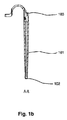
本発明の第1の実施形態によれば、図1a〜1cに係る拡張器100が提供される。拡張器100は、先端部102に第1の近位端および円錐状胴体のベース部103に第2の遠位端を有する略円錐状胴体101を具える。拡張器100は、挿入の際に周囲の組織に適合するために、可撓性材料から作製される。適切な材料は、スチレン系ブロック共重合体、ポリオレフィンブレンド、エラストマー性アロイ、および熱可塑性ポリウレタンなどの熱可塑性エラストマーである。拡張器100は、その第1の端部から第2の端部への貫通孔または管腔を具え、この貫通孔または管腔は、この貫通孔または管腔を通してガイドワイヤーを受けるために構成されている。拡張器100は、拡張器100がガイドワイヤーによって穿刺孔を通して引き込まれているときに、穿刺部位を拡張させる。第2の端部では、この拡張器はストラップ104などの連結部を具え、この連結部は、上記ベース部103から遠位方向に延在する。ストラップ104は、リング105などのボイスプロテーゼ保持部を有する。このように、この保持部は中央通路を有し、この中央通路は、ボイスプロテーゼのフランジがこの中央通路の近位方向および遠位方向に実質的に広げられているように、そのボイスプロテーゼの管状胴体がこの中央通路を通して配置されるように、構成されている。リング105は、ストラップ104の遠位端に配置される。このように、ストラップ104は、円錐状胴体101およびリング105を連結する。リング105は、ボイスプロテーゼをその中に収容するためのサイズに構成されており、そのため、ボイスプロテーゼの管状胴体は、リング105によって周囲を囲まれ、他方で、そのボイスプロテーゼのフランジは、リング105が管状胴体の周りに配置されるのを保つ。このように、ボイスプロテーゼが拡張器の保持部の中で配置位置にあるとき、このフランジは、保持部の中央通路の内径よりも大きい半径方向の広がり部分を有する。同時に、ストラップ104およびリング105の構成によって、ボイスプロテーゼが、ボイスプロテーゼのフランジのうちの1つまたは両方の変形なしに、リング105の中に予め装着されることが可能になる。このように、予め装着されたボイスプロテーゼを有する拡張器100は、直ちに使用できるアセンブリとして保存されてもよく、これにより、ボイスプロテーゼを気管食道壁に挿入する直前にボイスプロテーゼを拡張器の中に配置する必要がなくなる。また、リング105は、ストラップ104に結合されて、ボイスプロテーゼをリング105の中に装着するのを容易にする。なぜなら、このボイスプロテーゼのフランジは、リング105の両側から機能可能であり、ボイスプロテーゼおよびリング105が機能可能に配置されうる方向の数が増えるからである。さらには、リング105は、ストラップ104に結合されて、ボイスプロテーゼの改善された挿入を可能にする。なぜなら、リング105は、傾けた引き込み動作に起因して、ボイスプロテーゼの近位のフランジを、気管食道壁を通して、一度に1つの部分を押すことになるからである。従って、一度にフランジの一部分だけが気管食道壁を通して引き込まれる必要があり、これにより、気管食道壁上の応力が最小になる。
According to a first embodiment of the present invention, a
別の実施形態では、図2によれば、拡張器のリング205などのボイスプロテーゼ保持部が、いくつかの可撓性の肋材204の形態の連結部によって拡張器200に連結されている。図2に係る実施形態では、ボイスプロテーゼは、ボイスプロテーゼ保持部に配置されている。このように、図1の実施形態に係るストラップ104は、本実施形態では可撓性の肋材204によって置き換えられる。この場合、ボイスプロテーゼの管状胴体は、その1つのフランジがリング205の遠位方向に位置し、他方で他方のフランジは、リング205の近位側に、可撓性の肋材204の内部に半径方向に配置されている状態で、リング205の中に配置されてもよい。可撓性の肋材204は、可撓性の肋材204の内部に半径方向に配置されるフランジが完全に広げられることが可能になる可撓性を有する。この可撓性を提供するためのこの肋材204の適切な材料は、例えば、スチレン系ブロック共重合体、ポリオレフィンブレンド、エラストマー性アロイ、および熱可塑性ポリウレタンなどの熱可塑性エラストマーを含む群から選択されてもよい。このように、可撓性の肋材204は、拡張器200と一体的に形成されてもよい。これは、緩んだ状態にある肋材204が、円錐状胴体201から、ボイスプロテーゼのフランジの直径に対応して増大した内径に向かって遠位方向に延在し、その後、肋材204は、この増大した内径からリング205に向かって遠位方向に延在する場合にも、達成されうる。これに関して、可撓性の肋材204は、半径方向に外側に湾曲しており、ボイスプロテーゼの気管側のフランジが完全に広げられるようになる。配置の間、穿刺部位の圧力は肋材204に作用し、これは、次に、プロテーゼが穿刺部位を通るにつれて、プロテーゼの気管側のフランジを前方向に折り畳む。食道側のフランジが食道壁に到達すると、リング205の直径により、プロテーゼがリング205から放出されることが可能になる。
In another embodiment, according to FIG. 2, a voice prosthesis retainer, such as a
別の実施形態では、図3によれば、リング305は、蛇腹(bellow)形状の可撓性手段304(広げられている状態でプロテーゼの気管側のフランジを完全に取り囲んでいる)の形態の連結部によって拡張器300の円錐状胴体301に連結されている。蛇腹形状の可撓性手段304の一部は、その中に配置されるボイスプロテーゼを可視化するために、覆いのない状態であってもよい。その場合、当該ボイスプロテーゼの管状胴体は、その1つのフランジがリング305の遠位方向に位置し、他方で他方のフランジは、リング305の近位側に、可撓性手段304の内部に半径方向に配置されている状態で、リング305の中に配置されていてもよい。可撓性手段304は、可撓性手段304の内部に半径方向に配置されるフランジが完全に広げられることが可能になる可撓性を有してもよい。これは、緩んだ状態にある可撓性手段304が、円錐状胴体301から、ボイスプロテーゼのフランジの直径に対応して増大した内径に向かって遠位方向に延在し、その後、可撓性手段304はこの増大した内径からリング305に向かって遠位方向に延在する場合にも、達成されうる。これに関して、可撓性手段304は、半径方向に外側に向かって拡大されており、ボイスプロテーゼの気管側のフランジが実質的に広げられるようになる。配置の間、穿刺部位の圧力は実質的に円錐形の可撓性手段304に作用し、これは、次に、プロテーゼが穿刺部位を通るにつれて、プロテーゼの気管側のフランジを崩壊させ、前方向に折り畳む。食道側のフランジが食道壁に到達すると、リング305の直径により、プロテーゼがリング305から放出されることが可能になる。
In another embodiment, according to FIG. 3, the
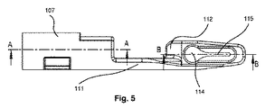
図2および3に係る実施形態は、下記の記載に関しては等しく可能であるとしても、ここで再び図1に示される実施形態を参照して、円錐状胴体101は、ワイヤーロック部106を受けるための、図4、5、6a、および6bに係る凹部をベース部103に有する。ワイヤーロック部106は、拡張器100の円錐状胴体101の厚い、遠位端に予め装着されてもよい。ワイヤーロック部106は、例えば、ポリフッ化ビニリデン(PVDF)、ポリプロピレン(PP)、およびポリアミドなどのいくぶんか剛体のプラスチック類でできていてもよい。ワイヤーロック106は、ガイドワイヤーを拡張器100に係止するために意図されている。従って、凹部は、先端部102からベース部103まで延在する貫通孔の一部分である。ワイヤーロック部106は、第1の近位端および第2の遠位端を具える管状胴体107を有する。ワイヤーロック部106は、近位端から最初に円錐状胴体の凹部に挿入されることになり、そのため、ワイヤーロック部106の円筒形の胴体の遠位端は、円錐状胴体101のベース部103と実質的に同じレベルに配置されることになろう。
Although the embodiment according to FIGS. 2 and 3 is equally possible with respect to the description below, referring again to the embodiment shown in FIG. 1, the
ワイヤーロック部106は、円錐状胴体101およびワイヤーロック部106の材料特性に起因して、半径方向の摩擦把持によって、適所に保持されてもよい。ワイヤーロック部106は、管状胴体107上に空洞を具えてもよく、他方で、円錐状胴体101の遠位端にある凹部は、円錐状胴体101におけるワイヤーロック部106の維持効果を得るために、ワイヤーロックにある空洞に嵌合する突起を具える。ワイヤーロック部106は、円錐状胴体101と一体化されていてもよい。
The
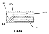
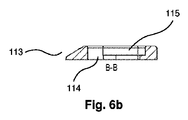
管状胴体107は、その近位端から遠位端まで、または遠位端から近位端までの貫通孔108、すなわち管状胴体107の管腔を具える。管状胴体107の近位端では、当該ワイヤーロック部は円錐形状の凹部109を有し、このため、この貫通孔は、ガイドワイヤーと実質的に同じ直径へと狭まる。管状胴体107の遠位端には、非貫通孔などの空洞110が具えられる。空洞110は、その中にガイドワイヤーの先端を受けるように構成されている。これに関して、空洞110の直径は、ガイドワイヤーの直径とほぼ同じであってもよい。この空洞は、その広がり部分が、管状胴体107を貫く貫通孔、すなわち管腔と平行であるように位置してもよい。管状胴体107の遠位端には、ワイヤーロック部106は、管状胴体107の遠位端から遠位方向に延在する肋材111を具える。肋材111は、管状胴体107の周辺部から、遠位方向に延在してもよい。さらには、肋材111は、管状胴体107と一体化されていてもよく、比較的剛体のプラスチック材料でできていてもよい。肋材111は、管状胴体107の中心軸に向かって内側方向に延在するツメ112を具える。このように、肋材111およびツメ112は、管状胴体107の遠位端から遠位方向に延在し、次いで管状胴体107の中心軸に向かって曲がるフック様要素を形成する。
The
図3に係る実施形態では、蛇腹形状の可撓性手段304の形状の連結部は、スリットを具えてもよく、これにより、ガイドワイヤーが可撓性手段304を出て、使用者によって可撓性手段304へ、空洞110へと再び導かれるようになる。略円錐状胴体101、201、301の近位端に変形可能な管状要素を設けることも可能である。このような変形可能な管状要素は、略円錐状胴体101、201、301の近位端に配置されてもよい。次いで、ガイドワイヤーは、この変形可能な管状要素の管腔の中へと挿入されてもよく、その後、この要素は、例えばプライヤーによる圧迫によって変形され、ガイドワイヤーは、その管腔の中に締め付け固定される。
In the embodiment according to FIG. 3, the connecting part in the shape of the bellows-shaped flexible means 304 may comprise a slit, whereby the guide wire exits the
管状胴体107の長手方向に延在する面であって、凹部/貫通孔および空洞110の中心軸を含む面、と交差する程度まで、ツメ112は、円筒形の胴体の中心軸に向かって延在してもよい。このように、ツメ112は、ガイドワイヤーの先端が空洞110に挿入された状態で、上記貫通孔を通って延びるガイドワイヤーの遠位方向の移動をブロックしてもよい。
To the extent that it intersects the longitudinally extending surface of the
ツメ112が、貫通孔/凹部についての長手方向の、遠位方向の広がり部分を覆う場合、すなわちツメ112が管状胴体107の管腔の中心軸と交差する場合、管状胴体107に面したツメ112の表面は、ツメ112と貫通孔/管腔/凹部の中心軸との交差部にわたって延在する面取り部113を具えてもよく、これにより、ガイドワイヤーをワイヤーロック部106に正しく装着することが容易になる。この面取り部は、ガイドワイヤーを側面へと、すなわち管状胴体107の外面に向かって導くことになろう。
A
肋材111は、その遠位端に、例えばツメ112に、鍵穴114も具えてよい。鍵穴114は、安全用ストラップを有するボイスプロテーゼの安全用ストラップを受けるように構成されていてもよい。この場合、製品の貯蔵寿命の間のボイスプロテーゼの永久歪みを回避するために、当該ボイスプロテーゼの安全用ストラップは、鍵穴114の幅広い部分に予め装着されてもよい。ボイスプロテーゼが、拡張器のリングから時期尚早に落下する場合、このプロテーゼ安全用ストラップは、鍵穴114の狭いスリット115の中へと引き込まれて、拡張器100、200、300に係止されることになろう。このように、このようなボイスプロテーゼは、気管と食道との間の壁にボイスプロテーゼを挿入する手順の際に拡張器100に固定されてもよい。また、安全用ストラップは、ボイスプロテーゼの挿入前にスリット115の中へと予め装着されてもよい。
The
ボイスプロテーゼを気管食道壁の中へと挿入する手順の間、ガイドワイヤーは、拡張器100の肉薄の、近位端を通って挿入される。このガイドワイヤーは、例えばポリプロピレンまたはポリアミドなどの適切なポリマーでできていてもよい。次いで、ガイドワイヤーは、ガイドワイヤーがワイヤーロック部106を突き抜けて出るまで、さらに押し出される。その場合、ツメ112の面取り部は、ガイドワイヤーを側面へと導いてもよく、ガイドワイヤーをワイヤーロック部106に正しく装着することを容易にしうる。ガイドワイヤーは、図7aに従って、係止手順を容易にするために、ワイヤーロック部106を通しておよそ100〜150mm引き込まれてもよい。ガイドワイヤーの遠位端は、図7bに従って、180°曲げられ、ガイドワイヤーが存在する貫通孔の隣の空洞110に挿入される。次いで、ガイドワイヤーは、図7cに従って、拡張器100の近位端から延在するガイドワイヤーの一部を引き込むことにより近位方向に引き込まれてもよく、これにより、ワイヤーロック部106の穴部の間で急カーブが作られ、これによって、ガイドワイヤーはワイヤーロック部107に、従って拡張器100にも係止される。従って、より有効でかつ組み立てるのが容易な、拡張器とガイドワイヤーとの間の取り付け機構を可能にする拡張器が得られる。なぜなら、穿刺孔を通して拡張器100を引き込むための引き込む力は、ねじ山のある部品およびアセンブリの際の複雑なねじ止めの動きの必要なしに、拡張器100とガイドワイヤーとの間の協働を厳しくすることになるだけだからである。ガイドワイヤーを拡張器100に固定する他の方法も、本発明の要旨から逸脱せずに、可能である。
During the procedure of inserting the voice prosthesis into the tracheoesophageal wall, the guide wire is inserted through the thin, proximal end of the
ワイヤーロック部106の2つの穴部、すなわち貫通孔/凹部および空洞に面したツメ112は、ガイドワイヤーが空洞110から外へ押し出されるのを防止する止め具として働く。これも、図7cに開示される。これに関して、空洞110の深さは、円筒形の胴体107の遠位端からツメ112までの距離に等しいかその距離よりも大きくてよい。
The two holes in the
当該ガイドワイヤー−拡張器−プロテーゼアセンブリは、穿刺部位を通して引き込まれ、穿刺孔を拡張して、その後のプロテーゼ配置を容易にする。拡張器100が穿刺孔を通り過ぎると、ボイスプロテーゼは、リング105によって穿刺孔を通して引き込まれる。穿刺孔の通過の際に、当該ボイスプロテーゼの気管側のフランジは、リング105によって、前方向に部分的に折り畳まれ、穿刺部位の周りの組織によって部分的に後ろ方向に折り畳まれる。リング105が穿刺孔を通過すると、リング105は、ボイスプロテーゼの気管側のフランジを越えて引き込まれ、こうして、気管側のフランジを前方向に押し出し、最終的に気管の中で広げられる。これは特に有益である。なぜなら、その場合、一度にフランジの一部だけが気管食道壁を通して引き込まれ、気管食道壁上の応力が最小にされるべきだからである。最後に、当該プロテーゼ安全用ストラップは、切断されてもよく、プロテーゼは、正しい位置に回転されてもよい。
The guidewire-dilator-prosthesis assembly is retracted through the puncture site to expand the puncture hole to facilitate subsequent prosthesis placement. As the
本発明は、特定の実施形態を参照して上に記載されたが、本発明は、本願明細書に示された特定の形態に限定されることは意図されていない。むしろ、本発明は、添付の特許請求の範囲によってのみ限定され、上記の特定の実施形態の他の実施形態も、これらの添付の特許請求の範囲の範囲内で等しく可能である。 Although the present invention has been described above with reference to specific embodiments, the present invention is not intended to be limited to the specific forms set forth herein. Rather, the invention is limited only by the accompanying claims and other embodiments of the specific embodiments described above are equally possible within the scope of these appended claims.
請求項において、用語「含む(comprises/comprising)」は、他の要素または工程の存在を排除しない。さらには、個々に記載されたが、複数の手段、要素または方法の工程は、例えば単独のユニットまたはプロセッサによって実行されてもよい。加えて、個々の特徴が、異なる請求項に含まれうるが、これらは、可能であれば、有利に組み合わされてもよく、異なる請求項に含まれることは、特徴の組み合わせが実行可能でなく、かつ/または有利ではないということを意味しない。加えて、単数形での言及は、複数形を排除しない。用語「1つの」、「第1の」、「第2の」などは、複数形を排除しない。請求項の中の参照記号は、単に明快にする例として提供されるに過ぎず、特許請求の範囲を限定するとは決して解釈されるべきではない。 In the claims, the term “comprises / comprising” does not exclude the presence of other elements or steps. Furthermore, although individually listed, a plurality of means, elements or method steps may be implemented by eg a single unit or processor. In addition, individual features may be included in different claims, but they may be combined advantageously if possible, and inclusion in different claims means that a combination of features is not feasible And / or does not mean that it is not advantageous. In addition, singular references do not exclude a plurality. The terms “one”, “first”, “second” and the like do not exclude a plurality. Reference signs in the claims are provided merely as a clarifying example and shall not be construed as limiting the scope of the claims in any way.
Claims (7)
前記拡張器(100)は、連結部(104)によって前記略円錐状胴体(101)に連結されたボイスプロテーゼ保持部(105)を具え、前記保持部(105)は中央通路を有し、
前記中央通路は、前記ボイスプロテーゼの前記フランジが前記中央通路の近位方向に広がるように、且つ前記ボイスプロテーゼの前記管状胴体が前記中央通路を通って配置されるように、構成されており、
前記連結部はストラップ(104)であり、前記ボイスプロテーゼ保持部はリング部(105)であることを特徴とする、拡張器(100)。 A dilator (100 ) for inserting a voice prosthesis into a tracheoesophageal wall, the voice prosthesis comprising a tubular body and a flange extending radially outward at an end of the tubular body. comprising the dilator that comprises a substantially conical body (10 1) having a base portion at a proximal end to a distal end (102) and a distal end (103), said dilator (10 0), the guide A wire lock (106) for locking a wire to the dilator (100, 200, 300);
The dilator (100 ) includes a voice prosthesis holding part (105 ) connected to the substantially conical body (101 ) by a connecting part (104 ) , the holding part (105 ) being a central passage. Have
It said central passageway, to so that spread proximally of the flange the central passage of the voice prosthesis, and such that the tubular body of the voice prosthesis is positioned through the central passage, is configured And
The dilator (100), wherein the connecting part is a strap (104) and the voice prosthesis holding part is a ring part (105 ) .
前記拡張器(200)は、連結部(204)によって前記略円錐状胴体(201)に連結されたボイスプロテーゼ保持部(205)を具え、前記保持部(205)は中央通路を有し、
前記中央通路は、前記ボイスプロテーゼの前記フランジが前記中央通路の近位方向に広がるように、且つ前記ボイスプロテーゼの前記管状胴体が前記中央通路を通って配置されるように、構成されており、
前記連結部は、いくつかの可撓性の肋材(204)であり、前記ボイスプロテーゼ保持部はリング部(205)であることを特徴とする、拡張器。 A dilator (200) for inserting a voice prosthesis into a tracheoesophageal wall, the voice prosthesis comprising a tubular body and a flange extending radially outward at an end of the tubular body. The dilator comprises a generally conical body (201) having a tip (102) at its proximal end and a base (103) at its distal end, the dilator (200) comprising a guide wire A wire lock (106) for locking to the dilator (200),
The dilator (200) comprises a voice prosthesis holding part (205) connected to the substantially conical body (201) by a connecting part (204), the holding part (205) having a central passage,
The central passage is configured such that the flange of the voice prosthesis extends proximally of the central passage, and the tubular body of the voice prosthesis is disposed through the central passage;
The dilator according to claim 1, wherein the connecting part is a number of flexible ribs (204), and the voice prosthesis holding part is a ring part (205).
前記拡張器(300)は、連結部(304)によって前記略円錐状胴体(301)に連結されたボイスプロテーゼ保持部(305)を具え、前記保持部(305)は中央通路を有し、
前記中央通路は、前記ボイスプロテーゼの前記フランジが前記中央通路の近位方向に広がるように、且つ前記ボイスプロテーゼの前記管状胴体が前記中央通路を通って配置されるように、構成されており、
前記連結部は可撓性の蛇腹形状の中空部(304)であり、ボイスプロテーゼのフランジが、前記可撓性の蛇腹形状の中空部(304)の中で広がることを可能にすることを特徴とする、拡張器。 A dilator (300) for inserting a voice prosthesis into a tracheoesophageal wall, the voice prosthesis comprising a tubular body and a flange extending radially outward at an end of the tubular body. The dilator comprises a generally conical body (301) having a tip (102) at its proximal end and a base (103) at its distal end, the dilator (300) comprising a guide wire A wire lock (106) for locking to the dilator (300),
The dilator (300) comprises a voice prosthesis holding part (305) connected to the substantially conical body (301) by a connecting part (304), the holding part (305) having a central passage,
The central passage is configured such that the flange of the voice prosthesis extends proximally of the central passage, and the tubular body of the voice prosthesis is disposed through the central passage;
The connecting portion is a hollow portion of the flexible bellows (304), the flange of the voice prosthesis, allows for Rukoto spread in the hollow portion of the flexible bellows (304) A dilator characterized by .
Applications Claiming Priority (3)
| Application Number | Priority Date | Filing Date | Title |
|---|---|---|---|
| SE0950462-2 | 2009-06-16 | ||
| SE0950462 | 2009-06-16 | ||
| PCT/EP2010/058427 WO2010146071A1 (en) | 2009-06-16 | 2010-06-16 | Dilator for inserting a voice prozhesis |
Publications (3)
| Publication Number | Publication Date |
|---|---|
| JP2012529944A JP2012529944A (en) | 2012-11-29 |
| JP2012529944A5 JP2012529944A5 (en) | 2013-08-01 |
| JP5647235B2 true JP5647235B2 (en) | 2014-12-24 |
Family
ID=42675913
Family Applications (1)
| Application Number | Title | Priority Date | Filing Date |
|---|---|---|---|
| JP2012515471A Active JP5647235B2 (en) | 2009-06-16 | 2010-06-16 | Dilator for inserting voice prosthesis |
Country Status (8)
| Country | Link |
|---|---|
| US (2) | US8721720B2 (en) |
| EP (1) | EP2442753B1 (en) |
| JP (1) | JP5647235B2 (en) |
| CN (1) | CN102458308B (en) |
| ES (1) | ES2690378T3 (en) |
| HK (1) | HK1170655A1 (en) |
| PL (1) | PL2442753T3 (en) |
| WO (1) | WO2010146071A1 (en) |
Families Citing this family (2)
| Publication number | Priority date | Publication date | Assignee | Title |
|---|---|---|---|---|
| FR2998162B1 (en) * | 2012-11-20 | 2016-02-12 | Protip | DEVICE FOR PLACING AND REMOVING A PROSTHESIS |
| US11931249B2 (en) | 2021-06-07 | 2024-03-19 | Freudenberg Medical, Llc | Easy voice prosthesis loading insertion device |
Family Cites Families (9)
| Publication number | Priority date | Publication date | Assignee | Title |
|---|---|---|---|---|
| US4808183A (en) * | 1980-06-03 | 1989-02-28 | University Of Iowa Research Foundation | Voice button prosthesis and method for installing same |
| US4439872A (en) * | 1981-10-06 | 1984-04-03 | Henley Cohn Julian L | Apparatus to assist esophageal speech |
| NL1000355C2 (en) * | 1995-05-12 | 1996-11-13 | Paul Ferdinand Schouwenburg | Voice prosthesis. |
| SE505552C2 (en) * | 1995-12-22 | 1997-09-15 | Atos Medical Ab | Method for mounting a flanged tubular body |
| NL1003043C2 (en) * | 1996-05-06 | 1997-11-07 | Paul Ferdinand Schouwenburg | Set for the insertion of a voice prosthesis in laryngectomers. |
| CN1158110C (en) * | 2001-12-10 | 2004-07-21 | 周星 | Memory alloy artificial larynx support |
| SE528922C2 (en) * | 2004-04-08 | 2007-03-13 | Atos Medical Ab | Method and apparatus for securely inserting and mounting a tubular device in a flexible wall and manufacturing method for said insertion device |
| US20090036983A1 (en) * | 2007-08-01 | 2009-02-05 | Helix Medical, Llc | Voice Prosthesis Gel Cap Loading Tool |
| DE202008000670U1 (en) * | 2008-01-17 | 2008-04-03 | Neubauer, Norbert | Device for fastening and attaching a tubular voice prosthesis in a flexible wall |
-
2010
- 2010-06-16 PL PL10722147T patent/PL2442753T3/en unknown
- 2010-06-16 ES ES10722147.5T patent/ES2690378T3/en active Active
- 2010-06-16 WO PCT/EP2010/058427 patent/WO2010146071A1/en active Application Filing
- 2010-06-16 JP JP2012515471A patent/JP5647235B2/en active Active
- 2010-06-16 US US13/378,590 patent/US8721720B2/en active Active
- 2010-06-16 CN CN201080026482.8A patent/CN102458308B/en active Active
- 2010-06-16 EP EP10722147.5A patent/EP2442753B1/en active Active
-
2012
- 2012-11-15 HK HK12111596.1A patent/HK1170655A1/en unknown
-
2014
- 2014-04-22 US US14/258,936 patent/US9320596B2/en active Active
Also Published As
| Publication number | Publication date |
|---|---|
| US8721720B2 (en) | 2014-05-13 |
| US9320596B2 (en) | 2016-04-26 |
| WO2010146071A1 (en) | 2010-12-23 |
| US20120165936A1 (en) | 2012-06-28 |
| US20140228952A1 (en) | 2014-08-14 |
| CN102458308B (en) | 2015-06-03 |
| HK1170655A1 (en) | 2013-03-08 |
| EP2442753A1 (en) | 2012-04-25 |
| CN102458308A (en) | 2012-05-16 |
| PL2442753T3 (en) | 2018-12-31 |
| EP2442753B1 (en) | 2018-07-18 |
| JP2012529944A (en) | 2012-11-29 |
| ES2690378T3 (en) | 2018-11-20 |
Similar Documents
| Publication | Publication Date | Title |
|---|---|---|
| US9510962B2 (en) | Stent delivery system | |
| EP2367504B1 (en) | Collapsible/expandable prosthetic heart valve delivery system and methods | |
| US7874981B2 (en) | Orifice introducer device | |
| JP6473449B2 (en) | Distal tip 2 piece external expansion anchor | |
| JP2012527930A (en) | Laparoscopic access port and port sleeve placement | |
| KR20150095629A (en) | Tympanostomy Tube and Insertion Device | |
| JP2008541842A (en) | Stomach fastening device | |
| US20230123143A1 (en) | Tympanostomy tube and a placement device | |
| US11737900B2 (en) | Systems and methods for anchoring and restraining gastrointestinal prostheses | |
| JP2010269160A (en) | Releasably-securable one-piece adjustable gastric band | |
| JP2009543660A (en) | Nipple dilator | |
| JP2011509714A (en) | Endoscope mooring device | |
| JP5647235B2 (en) | Dilator for inserting voice prosthesis | |
| JP3833484B2 (en) | Medical mantle | |
| GB2481056A (en) | Insertion device for a surgical instrument | |
| EP2477562B1 (en) | Pharynx protector | |
| CN111148477A (en) | Tissue anchor with hemostatic features | |
| JP5616250B2 (en) | Tracheoesophageal prosthesis indwelling device | |
| US20230032980A1 (en) | Multistage expandable loading dilator | |
| US20210236163A1 (en) | Flexible cannula | |
| CN118021380A (en) | Hemostatic clamp |
Legal Events
| Date | Code | Title | Description |
|---|---|---|---|
| A521 | Request for written amendment filed |
Free format text: JAPANESE INTERMEDIATE CODE: A523 Effective date: 20130613 |
|
| A621 | Written request for application examination |
Free format text: JAPANESE INTERMEDIATE CODE: A621 Effective date: 20130613 |
|
| A977 | Report on retrieval |
Free format text: JAPANESE INTERMEDIATE CODE: A971007 Effective date: 20140424 |
|
| A131 | Notification of reasons for refusal |
Free format text: JAPANESE INTERMEDIATE CODE: A131 Effective date: 20140507 |
|
| A521 | Request for written amendment filed |
Free format text: JAPANESE INTERMEDIATE CODE: A523 Effective date: 20140702 |
|
| TRDD | Decision of grant or rejection written | ||
| A01 | Written decision to grant a patent or to grant a registration (utility model) |
Free format text: JAPANESE INTERMEDIATE CODE: A01 Effective date: 20141007 |
|
| A61 | First payment of annual fees (during grant procedure) |
Free format text: JAPANESE INTERMEDIATE CODE: A61 Effective date: 20141106 |
|
| R150 | Certificate of patent or registration of utility model |
Ref document number: 5647235 Country of ref document: JP Free format text: JAPANESE INTERMEDIATE CODE: R150 |
|
| R250 | Receipt of annual fees |
Free format text: JAPANESE INTERMEDIATE CODE: R250 |
|
| R250 | Receipt of annual fees |
Free format text: JAPANESE INTERMEDIATE CODE: R250 |
|
| R250 | Receipt of annual fees |
Free format text: JAPANESE INTERMEDIATE CODE: R250 |
|
| R250 | Receipt of annual fees |
Free format text: JAPANESE INTERMEDIATE CODE: R250 |
|
| R250 | Receipt of annual fees |
Free format text: JAPANESE INTERMEDIATE CODE: R250 |
|
| R250 | Receipt of annual fees |
Free format text: JAPANESE INTERMEDIATE CODE: R250 |
|
| S111 | Request for change of ownership or part of ownership |
Free format text: JAPANESE INTERMEDIATE CODE: R313113 |
|
| S531 | Written request for registration of change of domicile |
Free format text: JAPANESE INTERMEDIATE CODE: R313531 |
|
| R350 | Written notification of registration of transfer |
Free format text: JAPANESE INTERMEDIATE CODE: R350 |
|
| RD02 | Notification of acceptance of power of attorney |
Free format text: JAPANESE INTERMEDIATE CODE: R3D02 |
|
| R250 | Receipt of annual fees |
Free format text: JAPANESE INTERMEDIATE CODE: R250 |