JP2009543660A - Nipple dilator - Google Patents
Nipple dilator Download PDFInfo
- Publication number
- JP2009543660A JP2009543660A JP2009520764A JP2009520764A JP2009543660A JP 2009543660 A JP2009543660 A JP 2009543660A JP 2009520764 A JP2009520764 A JP 2009520764A JP 2009520764 A JP2009520764 A JP 2009520764A JP 2009543660 A JP2009543660 A JP 2009543660A
- Authority
- JP
- Japan
- Prior art keywords
- dilator
- retainer
- arms
- catheter
- instrument
- Prior art date
- Legal status (The legal status is an assumption and is not a legal conclusion. Google has not performed a legal analysis and makes no representation as to the accuracy of the status listed.)
- Pending
Links
- 210000002445 nipple Anatomy 0.000 title description 15
- 238000000034 method Methods 0.000 claims abstract description 29
- 239000013013 elastic material Substances 0.000 claims abstract description 4
- 230000008878 coupling Effects 0.000 claims 1
- 238000010168 coupling process Methods 0.000 claims 1
- 238000005859 coupling reaction Methods 0.000 claims 1
- 230000035515 penetration Effects 0.000 abstract description 3
- 210000001519 tissue Anatomy 0.000 description 32
- 210000000013 bile duct Anatomy 0.000 description 13
- 210000001953 common bile duct Anatomy 0.000 description 9
- 210000001198 duodenum Anatomy 0.000 description 9
- 238000007459 endoscopic retrograde cholangiopancreatography Methods 0.000 description 7
- 210000005070 sphincter Anatomy 0.000 description 7
- 210000000277 pancreatic duct Anatomy 0.000 description 6
- 210000003484 anatomy Anatomy 0.000 description 4
- 239000000463 material Substances 0.000 description 4
- 230000003446 memory effect Effects 0.000 description 4
- 229910001000 nickel titanium Inorganic materials 0.000 description 4
- 230000009466 transformation Effects 0.000 description 4
- 206010051341 Bile duct stenosis Diseases 0.000 description 3
- 229910001566 austenite Inorganic materials 0.000 description 3
- 230000008901 benefit Effects 0.000 description 3
- 239000011248 coating agent Substances 0.000 description 3
- 238000000576 coating method Methods 0.000 description 3
- 229910000734 martensite Inorganic materials 0.000 description 3
- 238000002271 resection Methods 0.000 description 3
- 239000012781 shape memory material Substances 0.000 description 3
- 210000004872 soft tissue Anatomy 0.000 description 3
- 210000002784 stomach Anatomy 0.000 description 3
- 241000282341 Mustela putorius furo Species 0.000 description 2
- 201000001883 cholelithiasis Diseases 0.000 description 2
- 210000003238 esophagus Anatomy 0.000 description 2
- 238000000605 extraction Methods 0.000 description 2
- 239000012530 fluid Substances 0.000 description 2
- 208000001130 gallstones Diseases 0.000 description 2
- 238000010438 heat treatment Methods 0.000 description 2
- 238000003780 insertion Methods 0.000 description 2
- 230000037431 insertion Effects 0.000 description 2
- 230000014759 maintenance of location Effects 0.000 description 2
- 230000007246 mechanism Effects 0.000 description 2
- 210000000496 pancreas Anatomy 0.000 description 2
- -1 polyethylene, tetrafluoroethylene Polymers 0.000 description 2
- 230000002441 reversible effect Effects 0.000 description 2
- 229910001220 stainless steel Inorganic materials 0.000 description 2
- 239000010935 stainless steel Substances 0.000 description 2
- 239000004812 Fluorinated ethylene propylene Substances 0.000 description 1
- 206010033645 Pancreatitis Diseases 0.000 description 1
- 206010033647 Pancreatitis acute Diseases 0.000 description 1
- 208000031481 Pathologic Constriction Diseases 0.000 description 1
- 229920001774 Perfluoroether Polymers 0.000 description 1
- 201000003229 acute pancreatitis Diseases 0.000 description 1
- 239000000853 adhesive Substances 0.000 description 1
- 230000001070 adhesive effect Effects 0.000 description 1
- 230000002457 bidirectional effect Effects 0.000 description 1
- 230000000740 bleeding effect Effects 0.000 description 1
- 230000036760 body temperature Effects 0.000 description 1
- 239000000872 buffer Substances 0.000 description 1
- 230000008859 change Effects 0.000 description 1
- 230000000295 complement effect Effects 0.000 description 1
- 239000002872 contrast media Substances 0.000 description 1
- 238000001816 cooling Methods 0.000 description 1
- 230000000916 dilatatory effect Effects 0.000 description 1
- 230000000694 effects Effects 0.000 description 1
- HQQADJVZYDDRJT-UHFFFAOYSA-N ethene;prop-1-ene Chemical group C=C.CC=C HQQADJVZYDDRJT-UHFFFAOYSA-N 0.000 description 1
- 230000006870 function Effects 0.000 description 1
- 230000001939 inductive effect Effects 0.000 description 1
- 208000015181 infectious disease Diseases 0.000 description 1
- 210000004185 liver Anatomy 0.000 description 1
- 238000004519 manufacturing process Methods 0.000 description 1
- HLXZNVUGXRDIFK-UHFFFAOYSA-N nickel titanium Chemical compound [Ti].[Ti].[Ti].[Ti].[Ti].[Ti].[Ti].[Ti].[Ti].[Ti].[Ti].[Ni].[Ni].[Ni].[Ni].[Ni].[Ni].[Ni].[Ni].[Ni].[Ni].[Ni].[Ni].[Ni].[Ni] HLXZNVUGXRDIFK-UHFFFAOYSA-N 0.000 description 1
- 229920009441 perflouroethylene propylene Polymers 0.000 description 1
- 239000004033 plastic Substances 0.000 description 1
- 229920003023 plastic Polymers 0.000 description 1
- 229920000642 polymer Polymers 0.000 description 1
- 229920001343 polytetrafluoroethylene Polymers 0.000 description 1
- 239000004810 polytetrafluoroethylene Substances 0.000 description 1
- 229920002635 polyurethane Polymers 0.000 description 1
- 239000004814 polyurethane Substances 0.000 description 1
- 239000012858 resilient material Substances 0.000 description 1
- 239000000523 sample Substances 0.000 description 1
- 230000028327 secretion Effects 0.000 description 1
- 238000007493 shaping process Methods 0.000 description 1
- 238000001356 surgical procedure Methods 0.000 description 1
- 230000007704 transition Effects 0.000 description 1
- 230000003313 weakening effect Effects 0.000 description 1
Images


Classifications
-
- A—HUMAN NECESSITIES
- A61—MEDICAL OR VETERINARY SCIENCE; HYGIENE
- A61B—DIAGNOSIS; SURGERY; IDENTIFICATION
- A61B17/00—Surgical instruments, devices or methods
- A61B17/02—Surgical instruments, devices or methods for holding wounds open, e.g. retractors; Tractors
- A61B17/0218—Surgical instruments, devices or methods for holding wounds open, e.g. retractors; Tractors for minimally invasive surgery
-
- A—HUMAN NECESSITIES
- A61—MEDICAL OR VETERINARY SCIENCE; HYGIENE
- A61B—DIAGNOSIS; SURGERY; IDENTIFICATION
- A61B17/00—Surgical instruments, devices or methods
- A61B17/00234—Surgical instruments, devices or methods for minimally invasive surgery
- A61B2017/00292—Surgical instruments, devices or methods for minimally invasive surgery mounted on or guided by flexible, e.g. catheter-like, means
-
- A—HUMAN NECESSITIES
- A61—MEDICAL OR VETERINARY SCIENCE; HYGIENE
- A61B—DIAGNOSIS; SURGERY; IDENTIFICATION
- A61B17/00—Surgical instruments, devices or methods
- A61B17/0057—Implements for plugging an opening in the wall of a hollow or tubular organ, e.g. for sealing a vessel puncture or closing a cardiac septal defect
- A61B2017/00575—Implements for plugging an opening in the wall of a hollow or tubular organ, e.g. for sealing a vessel puncture or closing a cardiac septal defect for closure at remote site, e.g. closing atrial septum defects
- A61B2017/00623—Introducing or retrieving devices therefor
-
- A—HUMAN NECESSITIES
- A61—MEDICAL OR VETERINARY SCIENCE; HYGIENE
- A61F—FILTERS IMPLANTABLE INTO BLOOD VESSELS; PROSTHESES; DEVICES PROVIDING PATENCY TO, OR PREVENTING COLLAPSING OF, TUBULAR STRUCTURES OF THE BODY, e.g. STENTS; ORTHOPAEDIC, NURSING OR CONTRACEPTIVE DEVICES; FOMENTATION; TREATMENT OR PROTECTION OF EYES OR EARS; BANDAGES, DRESSINGS OR ABSORBENT PADS; FIRST-AID KITS
- A61F2/00—Filters implantable into blood vessels; Prostheses, i.e. artificial substitutes or replacements for parts of the body; Appliances for connecting them with the body; Devices providing patency to, or preventing collapsing of, tubular structures of the body, e.g. stents
- A61F2/02—Prostheses implantable into the body
- A61F2/04—Hollow or tubular parts of organs, e.g. bladders, tracheae, bronchi or bile ducts
- A61F2002/041—Bile ducts
Landscapes
- Health & Medical Sciences (AREA)
- Life Sciences & Earth Sciences (AREA)
- Surgery (AREA)
- Heart & Thoracic Surgery (AREA)
- Engineering & Computer Science (AREA)
- Biomedical Technology (AREA)
- Nuclear Medicine, Radiotherapy & Molecular Imaging (AREA)
- Medical Informatics (AREA)
- Molecular Biology (AREA)
- Animal Behavior & Ethology (AREA)
- General Health & Medical Sciences (AREA)
- Public Health (AREA)
- Veterinary Medicine (AREA)
- Surgical Instruments (AREA)
- Media Introduction/Drainage Providing Device (AREA)
Abstract
本発明は、体内開口部(105)を通じた侵入を容易にするための器具及び方法を提供し、これは複数のアームを有する拡張器(20)を備え、アームの各々は弾性材料で形成されて付形され、それにより遠位端は、拡張器が開放位置にあるとき互いに離間する傾向を有する。アームのうち少なくとも1本は、組織を把持するよう構成された鋭利部を有する係合部材を有する。拡張器が半径方向に展開して開放位置をとると、係合部材(32、34、36)が体内開口部に隣接する組織を把持して組織を開口部から離れる方に押し拡げ、それにより開口部の視覚化及び開口部への到達、あるいはそのどちらか一方が容易となる。続いて、拡張器が組織を拡張位置に保つ間に、カテーテル(50)又は他の装置が拡張器の1本又は複数のアームの間から体内開口部を通って挿入され得る。
The present invention provides an instrument and method for facilitating penetration through a body opening (105), which comprises a dilator (20) having a plurality of arms, each of which is formed of an elastic material. Shaped so that the distal ends tend to separate from each other when the dilator is in the open position. At least one of the arms has an engagement member having a sharp portion configured to grasp tissue. When the dilator is deployed radially and assumes the open position, the engagement members (32, 34, 36) grasp the tissue adjacent to the body opening and push the tissue away from the opening, thereby Visualizing the opening and / or reaching the opening is facilitated. Subsequently, a catheter (50) or other device may be inserted through the body opening from between one or more arms of the dilator while the dilator keeps the tissue in the expanded position.
Description
優先権主張
本発明は、2006年7月14日出願の「Papilla Spreader」と題される米国仮特許出願第60/830,835号の優先権の利益を主張し、その開示は全体として参照により本明細書に援用される。
This invention claims the benefit of priority of US Provisional Patent Application No. 60 / 830,835, filed July 14, 2006, entitled “Papilla Spreader,” the disclosure of which is incorporated by reference in its entirety. Incorporated herein by reference.
本発明は、体内開口部への侵入を容易にするための器具及び方法、及びより具体的には、体内開口部の周りの組織を把持し、その組織を拡張して引き離すことで開口部への侵入を容易にするために使用され得る装置に関する。 The present invention relates to an instrument and method for facilitating entry into a body opening, and more specifically to grasping tissue around the body opening and expanding and separating the tissue to the opening. It relates to a device that can be used to facilitate the penetration of
外科手術上、狭隘な体内開口部を通じて到達できることが望ましい、又は必要とされる場合は多くある。例えば、胆石を除去したり、又は胆管狭窄を処置したりするためには、患者の総胆管への到達が望ましいとされ得る。総胆管に到達するため、内視鏡的逆行性胆膵管造影法(ERCP)の手技が行われることもあり、ここでは医師が内視鏡を患者の口から食道、胃を通って十二指腸へと挿入する。内視鏡はワーキングルーメンを備えることができ、それを通じて、ワイヤガイド、カテーテル及び/又は他の装置が装填され得る。かかる装置は、内視鏡のワーキングルーメンを介して、十二指腸からファーター乳頭を通じ、次に総胆管へと案内され得る。 There are many situations where it is desirable or necessary to be able to reach through a narrow body opening surgically. For example, it may be desirable to reach the patient's common bile duct to remove gallstones or treat bile duct strictures. Endoscopic retrograde cholangiopancreatography (ERCP) may be performed to reach the common bile duct, where the doctor moves the endoscope from the patient's mouth through the esophagus and stomach into the duodenum. insert. The endoscope can include a working lumen through which a wire guide, catheter, and / or other device can be loaded. Such a device can be guided through the working duct of the endoscope, through the duodenum, through the ferrer teat, and then into the common bile duct.
ファーター乳頭を通じて総胆管内にワイヤガイド又は他の装置を前進させるとき、いくつかの問題に直面し得る。第一に、乳頭開口部の周囲の軟部組織の襞によってワイヤガイドの挿入が困難となることがあり、すなわち、組織の襞が開口部を通じた到達を部分的又は完全に遮断又は妨害し得る。さらに、十二指腸から総胆管内へと侵入するために必要な適切な角度を実現するのが困難なことがある。適切な角度が実現されない場合には、ワイヤガイドの侵入が逸れて、比較的傷つきやすい膵管に傷害が起こり得る。 Several problems can be faced when advancing a wire guide or other device through the Furter teat and into the common bile duct. First, the soft tissue fold around the nipple opening may make it difficult to insert the wire guide, i.e., the tissue fold can partially or completely block or prevent access through the opening. In addition, it may be difficult to achieve the proper angle required to enter the common bile duct from the duodenum. If the proper angle is not achieved, the wire guide penetration can be diverted and damage to the relatively vulnerable pancreatic duct can occur.
ERCP手技中の総胆管への到達を容易にするための公知の一技法は、オッディ括約筋において括約筋切除術を施術することである。括約筋切除術はいくつかの欠点を伴う。例えば、括約筋の切除は出血及び急性膵炎をもたらし得る。さらに、内視鏡的括約筋切除術はオッディ括約筋を永久的に破壊し、ひいては胆管系がさらなる感染症のリスクにさらされる。 One known technique for facilitating access to the common bile duct during an ERCP procedure is to perform a sphincterectomy at the oddy sphincter. Sphincter resection has several drawbacks. For example, resection of the sphincter can result in bleeding and acute pancreatitis. Furthermore, endoscopic sphincter resection permanently destroys the oddy sphincter, thus exposing the bile duct system to further infection risk.
従来から公知の技法の欠点をふまえると、解剖学的な開口部への到達を容易にすると同時に、患者の生体構造に傷害を与える可能性を低減する装置が必要とされている。 In view of the shortcomings of previously known techniques, there is a need for a device that facilitates access to the anatomical opening while reducing the potential for damage to the patient's anatomy.
本発明は、体内開口部、例えばファーター乳頭を通じた侵入を容易にするための器具及び方法を提供する。本器具は複数のアームを有する拡張器を備え、アームの各々は近位端と遠位端とを有する。各アームの近位端は拡張器の近位領域で接合され、そこから遠位に延在する。アームの各々が弾性材料で形成され付形されることにより、遠位端は、拡張器が開放位置にあるとき互いに離間し、拡張器が閉止位置にあるとき互いに近接する傾向を有する。 The present invention provides an instrument and method for facilitating entry through a body opening, such as a puffer papilla. The instrument includes a dilator having a plurality of arms, each arm having a proximal end and a distal end. The proximal end of each arm is joined at the proximal region of the dilator and extends distally therefrom. By forming and shaping each of the arms with a resilient material, the distal ends tend to be spaced apart from each other when the dilator is in the open position and close to each other when the dilator is in the closed position.
少なくとも1つの係合部材が各アームの遠位端近傍に配置される。各係合部材は組織を把持するよう構成された形状及び形態を有する。拡張器が閉止位置から開放位置に変形すると、係合部材は体内開口部の周囲の組織を把持し、体内開口部から離れる方向に組織を拡張する構成となる。組織が開口部から引き離されると、体内開口部への視界及び到達性、あるいはそのどちらか一方の向上が実現され得る。 At least one engagement member is disposed near the distal end of each arm. Each engagement member has a shape and configuration configured to grasp tissue. When the dilator is deformed from the closed position to the open position, the engaging member grasps the tissue around the opening in the body and expands the tissue in a direction away from the opening in the body. When the tissue is pulled away from the opening, improved visibility and / or reachability to the opening in the body can be achieved.
一実施形態において、拡張器は、近位端と遠位端とそれらの間に配置される第1のルーメンとを有するカテーテルを使用して標的部位に送達される。第1のルーメンは拡張器を収容して拡張器のアームを閉止位置に拘束するよう構成される。カテーテルを拡張器のアームに対し近位に後退させると、アームは所定の伸張した形態をとることができ、開放位置となる。必要に応じて、拡張器で組織を係合して体内開口部から離れる方向に拡張しながら、拡張器のアームのうち少なくとも2本の間から体内開口部を通ってカテーテルを前進させてもよい。 In one embodiment, the dilator is delivered to the target site using a catheter having a proximal end, a distal end, and a first lumen disposed therebetween. The first lumen is configured to receive the dilator and restrain the dilator arm in the closed position. When the catheter is retracted proximally relative to the dilator arm, the arm can assume a predetermined extended configuration and is in an open position. If desired, the catheter may be advanced through the body opening from between at least two of the arms of the dilator while engaging the tissue with the dilator and expanding away from the body opening. .
拡張器を取り外すためには、拡張器の近位領域及びアームの各々を覆うようにカテーテルを遠位に前進させ得る。拡張器は開放位置から閉止位置に変形し、ここでアームはカテーテルによって半径方向に拘束されるため、拡張器と組織との間の係合は弱まる。或いは、拡張器は手技後に患者の体内に残してもよい。 To remove the dilator, the catheter can be advanced distally over each of the proximal region of the dilator and each of the arms. The dilator deforms from the open position to the closed position, where the arms are radially constrained by the catheter, thus weakening the engagement between the dilator and the tissue. Alternatively, the dilator may remain in the patient's body after the procedure.
拡張器を確実に制御して展開するため、器具は第1のリテーナと第2のリテーナとを備え得る。第2のリテーナは、拡張器の展開前は第1のリテーナと連結されるよう構成され、さらに拡張器が展開された後は第1のリテーナから外されるように作製される。ある実施形態において、第1のリテーナと第2のリテーナとは、拡張器を捕捉して回収するために互いに再び係合するように構成される。 In order to reliably control and deploy the dilator, the instrument may comprise a first retainer and a second retainer. The second retainer is configured to be coupled to the first retainer before deployment of the dilator, and is configured to be removed from the first retainer after the dilator is deployed. In certain embodiments, the first retainer and the second retainer are configured to re-engage with each other to capture and retrieve the dilator.
本発明の他のシステム、方法、特徴及び利点は、以下の図及び詳細な説明を検討することにより当業者には明らかであるか、又は明らかとなるであろう。かかる追加的なシステム、方法、特徴及び利点の全ては本発明の範囲内であり、以下の特許請求の範囲に包含されることが意図される。 Other systems, methods, features and advantages of the present invention will be or will be apparent to those of ordinary skill in the art upon review of the following drawings and detailed description. All such additional systems, methods, features and advantages are within the scope of the invention and are intended to be covered by the following claims.
本発明は、以下の図面及び説明を参照することでより良く理解できる。図中の構成要素は必ずしも一定の縮尺とは限らず、本発明の原理を説明するうえで強調されている。さらに図では、同様の参照符号は、種々の図全てを通じて対応する部分を指示している。 The invention can be better understood with reference to the following drawings and description. The components in the figures are not necessarily to scale, emphasizing the principles of the invention. Moreover, in the figures, like reference numerals designate corresponding parts throughout the different views.
本願において、用語「近位」は医療手技中にほぼ医師に向かう方向を指し、一方で用語「遠位」は、医療手技中にほぼ患者の生体構造内の標的部位に向かう方向を指す。 In this application, the term “proximal” refers to the direction generally toward the physician during the medical procedure, while the term “distal” refers generally to the direction toward the target site within the patient's anatomy during the medical procedure.
本発明は、組織、例えば、体内開口部、通路又は体腔の周辺の軟部組織を拡張することで開口部への到達を容易にするのに好適な器具を提供する。好ましい実施形態において、本器具は、組織を係合するよう作製される拡張器を備える。拡張器は拘束された送達状態と非拘束状態とを有し、非拘束状態では複数のアームが半径方向外側に向かって展開することにより組織を係合し、組織を開口部から離れる方向に押し拡げる。 The present invention provides a device suitable for facilitating reaching an opening by dilating tissue, eg, soft tissue around a body opening, passage or body cavity. In a preferred embodiment, the device comprises a dilator that is made to engage tissue. The dilator has a constrained delivery state and an unconstrained state, where the arms engage the tissue by deploying radially outward and push the tissue away from the opening. spread.
図1A〜1Bを参照すると、本発明に係る拡張器の第1の実施形態が示されている。拡張器20は、近位領域40と、近位領域40から延在する複数のアーム22、24及び26とを備える。複数のアーム22、24及び26は、個別に製造され、その後近位領域40で共に接合されてもよく、又は製造中に一体に形成されてもよい。3本のアームが好ましいが、3本より多い、又は少ないアームが使用され得ることも企図される。
1A-1B, a first embodiment of a dilator according to the present invention is shown. The
複数のアーム22、24及び26は、それぞれ係合部材32、34及び36を備え、これらの係合部材は以下でさらに詳細に説明されるとおり、好ましくは外側に屈曲していて組織の把持が容易となっている。係合部材32、34及び36は、アーム22、24及び26と一体に形成されてもよく、又は1本若しくは複数のアーム22、24及び26の遠位領域に取り付けられる鋭利部材からなってもよい。
The plurality of
拡張器20は任意の好適な弾性材料、例えば、ステンレス鋼、ニチノール、プラスチックなどで作製され得る。加えて、アーム22、24及び26は、円形、四角形、三角形、パイ状、円錐台形などの断面形状を有し得る。
The
拡張器20はリテーナシステムを備えることにより、確実に制御して展開し得る。図1Aのループ状領域42のような第1のリテーナが、近位領域40と一体に形成されてもよく、又は近位領域40に別個に取り付けられてもよい。第1のリテーナには好ましくは送達/展開システムの第2のリテーナに設けられる形状と相補的な形状が設けられ、それにより第1のリテーナと第2のリテーナとが互いに嵌まり合って連係し得る。以下でさらに詳細に説明されるであろうとおり、第1のリテーナと第2のリテーナとを共に連結することにより、拡張器20の制御された展開が実現され得る。
The
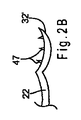
ここで図2A〜2Cを参照すると、拡張器20に好適な様々な係合部材が表される。図2Aでは、係合部材32が湾曲領域46を備え、これは示されるとおり外側に向かって湾曲している。図2Bでは、係合部材32’が1つ又は複数のとげ47を備え、これらは湾曲領域46に配置され、組織を把持するよう構成され得る。図2Cでは、係合部材32”が粗表面48を備え、これは湾曲領域46と一体化して形成され、組織を把持するよう構成され得る。係合部材32の様々な実施形態が図示されているが、拡張器20の係合部材34及び36、あるいはそのどちらか一方もまた、図2A〜2Cに示される特徴のいずれかを備え得る。
2A-2C, various engagement members suitable for the
ここで図3を参照すると、拡張器20を展開するために使用され得るカテーテル及び第1のリテーナシステムが表される。カテーテル50は、近位端と遠位端とそれらの間に延在する少なくとも1本のルーメンとを備える。図3の実施形態では、カテーテル50は3本のルーメン52、54及び56を有する。ルーメン56は、以下でさらに詳細に説明されるとおり、拡張器20を収容し、送達し、及びその展開を容易にするよう作製される。他のルーメンは、ワイヤガイド、結石を取り出すよう構成された摘出バスケット、結石を破砕するよう構成された砕石バスケット、胆管狭窄を処置するよう構成されたバルーンカテーテル及び他の装置、あるいはそのどちらか一方を収容するなど、他の補助的な機能を果たすよう構成され得る。他のルーメンはまた、造影剤を送り込むなど、流体を通過させるようにも構成され得る。カテーテル50の遠位領域はまた、外部バルーン(図示せず)を備えてもよく、これは選択的に膨張させて、例えば胆管狭窄を処置するよう構成される。
Referring now to FIG. 3, a catheter and first retainer system that can be used to deploy the
カテーテル50は好ましくは、1種又は複数の半剛性ポリマー類で形成され得る可撓性のチューブ状部材を備える。例えば、カテーテル50は、ポリウレタン、ポリエチレン、テトラフルオロエチレン、ポリテトラフルオロエチレン、パーフルオアルコキシル(perfluoalkoxl)、フッ素化エチレンプロピレンなどで製造され得る。カテーテルの長さ及び外径は、従来式内視鏡110(図7A〜7Cを参照)のワーキングチャンネルを通じて伸張させるのに十分なものであり得る。例えば、カテーテル50は、ワーキングチャンネル内に収まるように約6〜7フレンチの外径を備え得る。カテーテル50はまた、その外表面を被覆する親水性コーティングも備え得る。親水性コーティングはカテーテル50の外表面に塗布されると、カテーテルに柔軟性及び耐キンク性を与える。親水性コーティングはまた潤滑表面も提供して、内視鏡110のワーキングチャンネルを通じた移動が容易となり得る。
図3の実施形態では、リテーナシステムの第1のリテーナは拡張器20の近位領域40にあるループ状領域42の形態である。拡張器20と共に用いられるよう構成された第2のリテーナは、近位端と遠位端と遠位端に配置されるフック部材72とを有するワイヤ70の形態である。フック部材72はワイヤ70の遠位端で一体に形成されてもよく、又はそこに取り付けられてもよい。フック部材72は、拡張器20のループ状領域42に通して配置されるよう構成される。拡張器20及びワイヤ70がルーメン56内に配置されるとき、フック部材72はループ状領域42に通して配置され、アーム22、24及び26はワイヤ70より遠位の位置で閉止位置にある。閉止位置では、アーム22、24及び26は互いに近接し、ルーメン56の範囲内で拘束状態に保持される。
In the embodiment of FIG. 3, the first retainer of the retainer system is in the form of a looped
以下でさらに詳細に説明されるであろうとおり、カテーテル50をワイヤ70及び拡張器20に対して近位に後退させると、それによりアーム22、24及び26が露出し、図3に示されるとおり、アームが所定の半径方向に伸張した開放位置をとり得る。さらにカテーテル50が近位に後退してフック部材72を過ぎると、ループ状領域42がフック部材72と連結されている連結接点が露出し、それにより拡張器20をワイヤ70から解除できる。
As will be described in more detail below, retracting the
ここで図4を参照すると、拡張器20を展開するために使用され得る代替的リテーナシステムが表される。図4では、第2のリテーナは、近位端と遠位端と遠位端の近傍でロッド80を少なくとも部分的に貫通して配置される穴85とを有するロッド80を備える。ロッド80はルーメン56内に配置されるよう作製され、そこで長手方向に移動できるよう構成される。ロッド80は任意の好適な材料、例えばステンレス鋼からなり得る。
Referring now to FIG. 4, an alternative retainer system that can be used to deploy the
穴85は、拡張器20のループ状領域42を収容するよう構成される。より具体的には、ループ状領域42は、横方向に圧縮されて穴85に収まることが可能な十分な可撓性を有する。穴85はロッド80を部分的又は完全に貫通してもよく、好ましくは図4に示されるとおり、ループ状領域42を格納するよう傾斜している。好ましい実施形態において、ロッド80は直径が減少した領域86を備え、これは図4に示されるとおり、穴85の遠位に形成され、且つ穴85へと移行している。ループ状領域42が穴85の中に配置されると、拡張器20の近位領域40は直径が減少した領域86の真下に(それと隣接して)整列するため、器具全体としての半径方向の外形が大きくなることはない。さらに、アーム22、24及び26がロッド80より遠位の位置で閉止位置にあるとき、拘束されたアーム全体としての半径方向の外形は好ましくは、ロッド80の外径とほぼ同じである。従って、拘束されたアームによって器具の半径方向の送達外形が大きくなることは実質的にない。
The
以下でさらに詳細に説明されるであろうとおり、カテーテル50をワイヤ80及び拡張器20に対し近位に後退させると、それによりアーム22、24及び26が露出し、図4に示されるとおり、アームがそれらの所定の半径方向に伸張した開放位置をとり得る。さらにカテーテル50が近位に後退して穴85を過ぎると、ループ状領域42がロッド80と連結される連結接点が露出し、それにより拡張器20をロッド80から解除できる。
As will be described in more detail below, retracting the
ここで図5を参照すると、拡張器20を展開するために使用され得る代替的リテーナシステムが表される。第1のリテーナ95は拡張器20のアーム22、24及び26に動作可能に取り付けられる。第2のリテーナ90の近位端は図5に示されるとおり、作動ワイヤ91に取り付けられる。第1のリテーナ95と第2のリテーナ90とは好ましくは断面形状が円筒形であり、以下に記載されるとおり、嵌合されたときに実質的に同じ外径を有する。
Referring now to FIG. 5, an alternative retainer system that can be used to deploy the
第1のリテーナ95はそこに形成された部分的に円形のノッチ97を備え、且つノッチ97の近位に形成された円形のノブ96を有する。同様に、第2のリテーナ90はそこに形成された部分的に円形のノッチ93を備え、且つノッチ93の遠位に配置された円形のノブ92を有する。装置の送達中は、図5に示されるとおり、円形のノブ92がノッチ97と合致し、一方で円形のノブ96がノッチ93と合致し、それにより第1のリテーナ95が第2のリテーナ90に固定される。この実施形態において、カテーテルルーメン56の範囲内に配置されるとき第1のリテーナと第2のリテーナとは嵌まり合って一体に保持され、それによりリテーナの互いに対する移動が阻止される。カテーテル50の遠位端が近位に後退して第1のリテーナ95及び第2のリテーナ90を過ぎると、リテーナ間の連結領域が露出し、リテーナはそれ以上半径方向に拘束されないため、互いに解放可能に離脱する。
The
図3〜5は、拡張器20を送達するために使用され得る2つの例示的保持システムを示すが、他の多くの保持システムが設けられ得る。例えば、第1のリテーナ及び第2のリテーナは、全体として参照により本明細書に援用される2007年5月30日出願の米国特許出願第11/807,827号に記載されるリテーナ機構のいずれかに従い提供され得る。
3-5 show two exemplary retention systems that can be used to deliver the
上述されるとおり、拡張器20は、体内開口部の周囲の組織を拡張して開口部への到達を容易にするために使用され得る。図6〜7Dでは、拡張器20の一例示的使用が表され、ここでは拡張器20がERCP手技中のファーター乳頭を介した総胆管への到達を容易にする。
As described above, the
図6に示されるとおり、関連する生体構造として、肝臓Lから十二指腸Dへと繋がる総胆管Bが図示される。図6に示されるとおり、胆管Bはファーター乳頭105の直前で膵管Pと合流する。ファーター乳頭105は十二指腸Dの小さい開口部であり、胆管B及び膵管Pからの分泌物を排出する。図6に示されるとおり、胃Sもまた十二指腸Dに流れ込む。
As shown in FIG. 6, the common bile duct B connected from the liver L to the duodenum D is illustrated as a related anatomy. As shown in FIG. 6, the bile duct B merges with the pancreatic duct P immediately before the
ERCP手技の第1のステップでは、図6に概略的に示されるとおり、内視鏡110が患者の口から食道を通り、胃Sを通じて十二指腸D内に挿入される。好ましい実施形態において、内視鏡110は側視内視鏡である。内視鏡110の遠位端はファーター乳頭105の周囲に位置決めされる。ファーター乳頭105の位置は、膵臓(図示せず)を視覚化し、次に胆管B及び膵管P、あるいはそのどちらか一方を十二指腸Dの壁及びファーター乳頭105まで辿ることにより特定され得る。
In the first step of the ERCP procedure, an
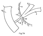
ERCP手技において胆管Bに到達し、及びそのアクセス、あるいはそのどちらか一方を維持することは、様々な理由から困難であり得る。第一に、ファーター乳頭105の小さい開口部に到達するのは厄介であり得る。例えば、図7Aに示されるとおり、乳頭開口部は軟部組織Tによって完全又は部分的に覆われている可能性がある。さらに、乳頭を通じたカニューレ挿入が実現されたとしても、図6に図示されるとおり、膵管Pは側方にいくらか傾斜しており、胆管Bではなく膵管Pに到達し易い。従って、一態様に従えば、拡張器20が提供されることによりERCP手技中の胆管Bへの到達が容易となり得る。
Reaching and / or maintaining access to bile duct B in an ERCP procedure can be difficult for a variety of reasons. First, it can be cumbersome to reach a small opening in the
図7Aでは、上記に説明されるとおり、内視鏡110が患者の十二指腸Dまで進められ、ファーター乳頭105の周囲に位置決めされている。カテーテル50は内視鏡110のワーキングルーメン(図示せず)を通じて前進させ、図7Aに示されるとおり、ファーター乳頭105に隣接して位置決めされる。
In FIG. 7A, the
図3〜5に関連して上記に説明されるとおり、拡張器20は好ましくは、カテーテル50のルーメン56に事前に装填される。ルーメン56がアーム22、24及び26を閉止位置に拘束することでアームは互いに近接している。好ましい実施形態において、拡張器20は、第1のリテーナと第2のリテーナとを備えるリテーナシステムを使用して制御された方式で展開されるよう構成される。第1のリテーナが拡張器20の近位領域にループ状領域42を備えてもよく、一方で第2のリテーナがフック部材72を有するワイヤ70(図3)を備えてもよく、又は穴85を有するロッド80(図4)か、若しくは別の保持手段を備えてもよい。カテーテル50の送達中、第1のリテーナと第2のリテーナとが共に連結されることにより、ルーメン56内に拡張器20が固定される。
As described above in connection with FIGS. 3-5, the
図7Bに示される次のステップにおいて、カテーテル50を拡張器20に対し近位に後退させると、それにより拡張器のアームの係合部材32、34及び36が露出して、それ以上半径方向に拘束されなくなる。このとき、係合部材32、34及び36はファーター乳頭105の周囲の組織Tを把持し、図7Bに図示されるとおり、組織Tを半径方向に乳頭開口部から引き離すように押し拡げる。カテーテル50をさらに後退させると、アーム22、24及び26の遠位端が拡張して互いに離間する。好ましくは、拡張器20を展開する前にルーメン56をファーター乳頭105と整列させることで、アーム22、24及び26が半径方向外側に伸張するとき、アームが乳頭開口部から離れて伸張するようにする。
In the next step shown in FIG. 7B, retracting the
アーム22、24及び26の展開後、カテーテル50を拡張器20に対しさらに後退させることで、第1のリテーナと第2のリテーナとの間の連結接点を露出させ得る。図3の実施形態では、カテーテル50をフック部材72の近位に後退させることにより、拡張器20のループ状領域42をワイヤ70から解除できる。図4の実施形態では、カテーテル50を穴85の近位に後退させることにより、拡張器20のループ状領域42をロッド80から解除できる。従って、拡張器20はファーター乳頭105の前の所定位置に確実に残る。
After deployment of the
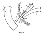
ここで図7Cを参照すると、次のステップでは、ワイヤガイド90を拡張器20の1本又は複数のアーム22、24及び26の間に遠位に前進させて、胆管B内まで案内し得る。ワイヤガイド90は、カテーテル50の専用のワイヤガイドルーメン、例えば図3のルーメン52を通じて前進させ得る。続いて、カテーテル50をワイヤガイド90に従い、図7Cに示されるとおり(この図では、アーム26がカテーテル50により隠れていることに留意されたい)、拡張器20の1本又は複数のアーム22、24及び26の間を胆管B内へと遠位に前進させ得る。
Referring now to FIG. 7C, in the next step, the
有利な点としては、拡張器20のアームがファーター乳頭105から離れた拡張位置で組織Tを保持するため、内視鏡110から乳頭開口部を見ることがより容易となり得る。従って、ファーター乳頭105にカニューレ挿入して胆管Bへの到達を実現することがより容易となり得る。重要なことには、膵管Pに侵入してそれに傷害を与える可能性が低減され得る。
Advantageously, it may be easier to see the nipple opening from the
必要に応じて、カテーテル50が胆管B内に配置されている間に、1つ又は複数の手技が施術され得る。例えば、カテーテルルーメン54を通じて摘出バスケット(図示せず)を前進させ、それを使用して胆管B内に詰まった胆石を除去し得る。或いは、上述されるとおり、例えばカテーテル50の外表面に膨張バルーンを配置することによって、カテーテル50を使用して胆管狭窄を処置し得る。さらに、アクセスが実現され、維持されると、砕石プローブ又は他の装置が乳頭開口部を介して胆管B内に挿入され得る。
If desired, one or more procedures may be performed while the
所望の外科手技が完了したら、拡張器20は患者の体内に残されてもよく、又は取り出されてもよい。拡張器20を取り出すためには、7A〜7Bの1つ又は複数のステップが逆の順序で用いられ得る。例えば、ワイヤ70の遠位端のフック部材72を前進させて拡張器20のループ状領域42と係合させ得る。次にカテーテル50を遠位に前進させることでルーメン56を拡張器20の近位領域40上に前進させてアーム22、24及び26を共に折り畳んでもよく、それにより拡張器20を取り出すことが可能である。或いは、別のシースを通じて鉗子又は他の把持装置を展開し、鉗子を使用して拡張器20を把持し、シース内に引き込んでもよい。カテーテル又はシースを近位領域40上に、ひいてはアーム22、24及び26上に前進させると、アームは半径方向内側に動いて組織Tから外れる。カテーテル又はシースを前進させると、アーム22、24及び26はその中に半径方向に拘束され得る。必要に応じて、ループ状領域42を係合することにより、拡張器20をカテーテル又はシース内で近位に後退させてもよい。
Once the desired surgical procedure is complete, the
或いは、図7Dに示されるとおり、拡張器20は患者の体内に残されてもよい。拡張器20はある時間をかけて組織Tから離脱するよう作製されてもよく、自然に患者の体内を通り抜け得る。拡張器20はまた、最終的に溶解して無害なまま体から出て行く生分解性材料からなってもよい。必要に応じて、拡張器20は組織Tを永久的に係合するよう設計されてもよく、この場合、拡張器は患者の体内に残ることになる。
Alternatively, as shown in FIG. 7D, the
さらなる代替的実施形態において、拡張器20は形状記憶材料製の場合には取り出し可能であってもよく、このとき拡張器は、特定の冷たい、又は熱い媒体が付与されると組織から容易に外れる弛緩形態をとることができる。より具体的には、形状記憶材料は、以前の形状又は形態を「記憶」して、それに戻ることができる実質的に可逆的な相変態を受け得る。例えば、ニッケル−チタン合金の場合、オーステナイト相とマルテンサイト相との間の変態は、冷却及び加熱、あるいはそのどちらか一方によって(形状記憶効果)、又は応力を等温的に付与及び除去、あるいはそのどちらか一方により(超弾性効果)生じ得る。特徴としてオーステナイトはより強固な相であり、マルテンサイトはより変形し易い相である。
In a further alternative embodiment, the
形状記憶効果の例では、オーステナイト相の初期形態を有するニッケル−チタン合金が冷却されて変態点(Mf)を下回るとマルテンサイト相となり、このとき第2の形態に変形され得る。別の変態点(Af)まで加熱すると、材料は自然にその当初の形態に戻り得る。一般的に、記憶効果は一方向であり、つまりある形態から別の形態への自然な変化は加熱したときにのみ起こる。しかしながら、双方向の形状記憶効果を得ることは可能であり、ここでは形状記憶材料は冷却しても加熱しても形状が自然に変化する。 In the example of the shape memory effect, when the nickel-titanium alloy having the initial form of the austenite phase is cooled and falls below the transformation point (M f ), it becomes a martensite phase and can be transformed into the second form at this time. Upon heating to another transformation point (A f ), the material can spontaneously return to its original form. In general, the memory effect is unidirectional, that is, the natural change from one form to another occurs only when heated. However, it is possible to obtain a bidirectional shape memory effect, where the shape memory material naturally changes its shape when it is cooled or heated.
こうした形状記憶特性を拡張器20に付与すると、カテーテル50を後退させて拡張器20を体温にさらし、アーム22、24及び26を半径方向外側に伸張させて組織を把持させることが可能となる。拡張器20を取り出すことが所望される場合、例えば、カテーテル50を通じて流体を注入するか、又は温度誘導要素を直接接触させることにより第2の所定の温度を拡張器20に付与してアーム22、24及び26を弛緩状態に変化させてもよく、このときアームは組織からより離れ易くなる。この温度を付与すると、拡張器20は比較的非侵襲性の配置をとることができ、従って体内を安全に通過できる。
When such shape memory characteristics are imparted to the
ここで図8を参照すると、代替的な拡張器が表される。拡張器120は、付勢部材140が追加されていることを主に除いては、図1〜7の拡張器20と同様である。図8に示されるとおり、付勢部材140はアーム122及び126のそれぞれの係合部材132及び136と直接連結され得る。付勢部材140はまた、係合部材より近位の位置でアーム122、124及び/又は126と直接連結されてもよい。図示されるとおり、付勢部材140は、複数の屈曲部により分割される複数の実質的に直線状の部分を有する円筒形のジグザグ形状の部材からなり得るが、他の形態も可能である。付勢部材140はニッケル−チタン合金を使用して製造されてもよく、外形を小さくした送達形態と半径方向に伸張した拡張形態とを備え得る。伸張した状態では、付勢部材140はアーム22、24及び26の単独での使用と比較してより大きい組織係合面積を提供でき、さもなければ到達が困難な体内開口部への侵入を容易にし得る。
Referring now to FIG. 8, an alternative dilator is represented. The
ファーター乳頭を介した総胆管への到達を容易にすることについて参照されているが、拡張器20は組織の拡張を補助することで、他の多くの狭隘な体内開口部、通路、管路又は体腔に到達するために使用されてもよい。或いは、拡張器20は、通路の周囲の組織ではなく、環状の通路それ自体を開大するために使用されてもよい。後者の実施形態では、アーム22、24及び26はより強い半径方向力を有するよう設計され、例えば、オッディ括約筋などの括約筋又は別の通路を拡張して開大し得る。
While reference is made to facilitating access to the common bile duct through the ferret nipple, the
ここで図9〜14を参照すると、拡張器のさらなる代替的実施形態が表される。図9では、拡張器200は第1の部分202と第2の部分204とから形成される。第1の部分202は第1のアーム212と第2のアーム213とを備え、これらのアームは中心領域211により隔てられている。同様に、第2の部分204は第3のアーム216と第4のアーム217とを備え、図9に示されるとおり、これらのアームは中心領域215により隔てられている。4本のアーム212、213、216及び217は、拡張器20のアーム22、24及び26に関して上記で概して説明されるとおり提供され得る。特に、4本のアーム212、213、216及び217の各々は外側に曲がった屈曲部及び係合部材、あるいはそのどちらか一方を備えて組織を把持するよう構成され得る。
With reference now to FIGS. 9-14, a further alternative embodiment of a dilator is depicted. In FIG. 9, the
好ましい実施形態において、中心領域211及び215は、180〜360度にわたる略円周形状に曲がったワイヤ又は他の好適な材料からなり得る。或いは、中心領域211及び215は、以下に記載される目的のため、360度のループ又はU字型などを形成するワイヤからなってもよい。
In a preferred embodiment, the
図10〜11を参照すると、次のステップでは、第1の部分202と第2の部分204とが共に連結される。図10では、中心領域211と215とが整列され、次に接着剤220を使用して共に連結され得る。連結されるとき、拡張器200の4本のアーム212、213、216及び217は好ましくは相反する周方向に伸張し、上記に説明されるとおり、組織の拡張を容易にする。或いは、図11に示されるとおり、中心領域211と215とは共に編組されるか、又は撚り合わされてもよい。図10〜11に示されるいずれの実施形態においても、重なり合う部分はループ又はU字型などを形成し得る。さらなる代替的実施形態においては、中心領域211及び215を覆ってスリーブを配置することにより、第1の部分202と第2の部分204とを共に固定するのを補助してもよい。
Referring to FIGS. 10-11, in the next step, the
ここで図12を参照すると、拡張器200の送達に好適なカテーテルが表される。カテーテル240は好ましくは、近位端と遠位端とそれらの間に延在する少なくとも1本のルーメン244とを備える。カテーテル240はさらに、図12に示されるとおり、そこに形成された少なくとも1つの隆起部242を有する外表面を備える。この実施形態において、拡張器200は内部ルーメンを通じてではなく、実質的にカテーテル240の外側から送達される。具体的には、重なり合う中心領域211と215とが、摩擦嵌めを用いるか、又は隆起部242の中で所定位置に保持されるか、又は追加的な固定機構を用いることによりカテーテル240の周囲を囲むように配置され得る。
Referring now to FIG. 12, a catheter suitable for delivery of the
図12では、少なくとも1本のフィラメント250を用いて拡張器200の4本のアーム212、213、216及び217が一体に保持され送達状態にある。フィラメント250は好ましくはルーメン244を通じて延在し、カテーテル240の全長に及ぶ。拡張器200が所望の場所に位置決めされたら、フィラメント250の近位端を近位に後退させて、それによりアーム212、213、216及び217を解除し、上記の図10〜11に示されるとおり、それらを半径方向に伸張させる。
In FIG. 12, at least one
図13に示される代替的実施形態では、分割可能なシースを用いて拡張器200の4本のアーム212、213、216及び217が一体に保持され送達状態にある。分割可能なシース260は近位端がワイヤ264と連結され、ワイヤ264はルーメン244を通じて長手方向に延在する。分割可能なシース260はさらに少なくとも1本の破断線262を備える。使用時は、拡張器200の展開に望ましい状態となったら、ワイヤ264をルーメン244内で近位に後退させて、それにより少なくとも1本の破断線262を引き裂き、拡張器200を解除する。このとき、分割可能なシース260はルーメン244内に引き込むことができ、一方でアーム212、213、216及び217は解除され、上記の図10〜11に図示されるとおり、半径方向に伸張して組織を係合する。
In an alternative embodiment shown in FIG. 13, the four
図14を参照すると、さらなる代替的実施形態において、拡張器300は、共に連結される2つの別個の構成部品ではなく、単一の構成部品で製造されることを主に除いては、図9〜11の拡張器200と同様である。拡張器300は、図14に示されるとおり、環状形態の基部302と、そこから延在する複数の一体型アーム303〜306とを備える。基部302は、例えば摩擦嵌めを用いるか、又は隆起部242に設置することによりカテーテル240の外表面に被せると適合するサイズであり得る。或いは、拡張器300は、図3〜4に関して上記に概して記載されるとおり、カテーテルのルーメンの内部を通じて送達するよう作製されてもよい。
Referring to FIG. 14, in a further alternative embodiment, the
本発明の様々な実施形態が記載されたが、さらに多くの実施形態及び実施態様が本発明の範囲内で可能であることを当業者は理解するであろう。従って本発明は、特許請求の範囲及びその等価物を踏まえることを除いては限定されない。 While various embodiments of the invention have been described, those skilled in the art will appreciate that many more embodiments and implementations are possible within the scope of the invention. Accordingly, the invention is not limited except in light of the claims and their equivalents.
Claims (22)
近位領域と複数のアームとを有する拡張器であって、前記アームの各々が近位端と遠位端とを有し、前記アームの各々の前記近位端が前記拡張器の前記近位領域に接合されてそこから遠位に延在し、前記アームの各々が、前記拡張器が開放位置にあるとき前記遠位端が互いに離間し、前記拡張器が閉止位置にあるとき前記遠位端が互いに近接するように、弾性材料で形成されて付形されている拡張器と、
各アームの前記遠位端の近傍に配置される少なくとも1つの係合部材であって、各係合部材が組織を把持するよう構成される係合部材とを備え、
前記拡張器の前記閉止位置から前記開放位置への変形が、前記体内開口部の周囲の組織を拡張するよう構成されている器具。 An instrument for facilitating entry through a body opening,
A dilator having a proximal region and a plurality of arms, each of the arms having a proximal end and a distal end, wherein the proximal end of each of the arms is the proximal of the dilator. Joined to the region and extending distally therefrom, each of the arms being spaced apart from each other when the dilator is in the open position and distal when the dilator is in the closed position A dilator formed of an elastic material and shaped so that the ends are close to each other;
At least one engagement member disposed near the distal end of each arm, each engagement member configured to grasp tissue;
An instrument configured such that deformation of the dilator from the closed position to the open position expands tissue around the body opening.
前記拡張器の展開前は前記第1のリテーナに連結されるよう構成され、さらに、前記拡張器が展開された後は前記第1のリテーナから外されるよう作製される第2のリテーナと、
をさらに備える、請求項1に記載の器具。 A first retainer disposed proximate to the proximal region of the dilator;
A second retainer configured to be coupled to the first retainer prior to deployment of the dilator, and further configured to be removed from the first retainer after the dilator is deployed;
The instrument of claim 1, further comprising:
複数のアームであって、前記アームの各々が近位端と遠位端とを有するアームを有する拡張器を提供するステップと、
前記拡張器を標的組織の周囲に位置決めするステップと、
前記拡張器を展開することにより、前記アームの各々の前記遠位端を互いに離間させて、前記標的組織を前記体内開口部から離れる方向に拡張させることで前記体内開口部への侵入を容易にするように前記標的組織を係合するステップと、
を含む、方法。 A method for facilitating entry through a body opening,
Providing a dilator having a plurality of arms, each arm having a proximal end and a distal end;
Positioning the dilator around a target tissue;
By deploying the dilator, the distal ends of each of the arms are spaced apart from each other and the target tissue is expanded away from the body opening to facilitate entry into the body opening. Engaging the target tissue to:
Including a method.
前記拡張器を前記第1のルーメン内で前記閉止位置に拘束するステップと、
前記カテーテルを前記拡張器に対し近位に後退させることにより前記アームを互いに離間させて開放位置にするステップと、
をさらに含む、請求項11に記載の方法。 Providing a catheter having a proximal end, a distal end, and a first lumen disposed between the proximal end and the distal end;
Constraining the dilator to the closed position within the first lumen;
Separating the arms from each other to an open position by retracting the catheter proximally with respect to the dilator;
The method of claim 11, further comprising:
前記拡張器の展開前に前記第1のリテーナを第2のリテーナと連結するステップと、
前記拡張器が展開された後に前記第1のリテーナを前記第2のリテーナから外すステップと、
をさらに含む、請求項10に記載の方法。 Providing a first retainer disposed proximate to a proximal region of the dilator;
Coupling the first retainer with a second retainer prior to deployment of the dilator;
Detaching the first retainer from the second retainer after the dilator has been deployed;
The method of claim 10, further comprising:
近位領域と複数のアームとを有する拡張器であって、前記アームの各々が近位端と遠位端とを有し、前記アームの各々の前記近位端が第1のリテーナに接合され、そこから遠位に延在し、前記アームの各々が、前記拡張器が開放位置にあるとき前記遠位端が互いに離間し、前記拡張器が閉止位置にあるとき前記遠位端が互いに近接するように、弾性材料から形成されて付形されている拡張器と、
各アームの前記遠位端の近傍に配置される少なくとも1つの係合部材であって、各係合部材が前記体内開口部の周囲にある組織を把持するよう構成される係合部材と、
前記拡張器の展開前は前記第1のリテーナと連結されるよう構成され、さらに、前記拡張器が展開された後は前記第1のリテーナから外されるよう作製される第2のリテーナと、
近位端と遠位端とそれらの間に配置される第1のルーメンとを有するカテーテルであって、前記第1のルーメンが前記拡張器を収容して前記拡張器の前記アームを前記閉止位置に拘束するよう構成される、カテーテルと、
を備え、前記拡張器が前記開放位置にあるとき、前記カテーテルが前記拡張器の前記アームのうち少なくとも2本の間を前進できるようにされている外径を前記カテーテルが備える器具。 An instrument for facilitating entry through a body opening,
A dilator having a proximal region and a plurality of arms, each of the arms having a proximal end and a distal end, wherein the proximal end of each of the arms is joined to a first retainer. Extending distally therefrom, each of the arms being spaced apart from each other when the dilator is in an open position and the distal ends being close to each other when the dilator is in a closed position A dilator formed from an elastic material and shaped,
At least one engagement member disposed near the distal end of each arm, wherein each engagement member is configured to grasp tissue surrounding the body opening;
A second retainer configured to be coupled to the first retainer before deployment of the dilator, and further configured to be removed from the first retainer after the dilator is deployed;
A catheter having a proximal end, a distal end, and a first lumen disposed therebetween, wherein the first lumen houses the dilator and places the arm of the dilator in the closed position. A catheter configured to be constrained to,
And the catheter has an outer diameter adapted to allow the catheter to advance between at least two of the arms of the dilator when the dilator is in the open position.
Applications Claiming Priority (2)
| Application Number | Priority Date | Filing Date | Title |
|---|---|---|---|
| US83083506P | 2006-07-14 | 2006-07-14 | |
| PCT/US2007/015803 WO2008008384A2 (en) | 2006-07-14 | 2007-07-11 | Papilla spreader |
Publications (2)
| Publication Number | Publication Date |
|---|---|
| JP2009543660A true JP2009543660A (en) | 2009-12-10 |
| JP2009543660A5 JP2009543660A5 (en) | 2010-08-26 |
Family
ID=38857911
Family Applications (1)
| Application Number | Title | Priority Date | Filing Date |
|---|---|---|---|
| JP2009520764A Pending JP2009543660A (en) | 2006-07-14 | 2007-07-11 | Nipple dilator |
Country Status (7)
| Country | Link |
|---|---|
| US (1) | US8425412B2 (en) |
| EP (1) | EP2040788B1 (en) |
| JP (1) | JP2009543660A (en) |
| AT (1) | ATE547143T1 (en) |
| AU (1) | AU2007272981B2 (en) |
| CA (1) | CA2659591C (en) |
| WO (1) | WO2008008384A2 (en) |
Cited By (1)
| Publication number | Priority date | Publication date | Assignee | Title |
|---|---|---|---|---|
| JP2017513652A (en) * | 2014-06-18 | 2017-06-01 | エックスルミナ, インコーポレイテッド | Biliary stent |
Families Citing this family (15)
| Publication number | Priority date | Publication date | Assignee | Title |
|---|---|---|---|---|
| US9610072B2 (en) * | 2009-11-02 | 2017-04-04 | Apx Opthalmology Ltd. | Iris retractor |
| US20110178513A1 (en) * | 2010-01-21 | 2011-07-21 | CreamOptee Industries Inc. | Method and device for internal tissue removal |
| US9017246B2 (en) * | 2010-11-19 | 2015-04-28 | Boston Scientific Scimed, Inc. | Biliary catheter systems including stabilizing members |
| US9445801B2 (en) | 2013-03-15 | 2016-09-20 | Cook Medical Technologies Llc | Medical device with selective rigidity |
| US20140336464A1 (en) * | 2013-05-08 | 2014-11-13 | Boston Scientific Scimed, Inc. | Expansion devices and methods of use thereof |
| US10524813B2 (en) | 2015-04-19 | 2020-01-07 | Bam Medical Ltd. | Frenulum spreader |
| US11607227B2 (en) | 2017-03-21 | 2023-03-21 | Teleflex Medical Incorporated | Surgical clip and clip applier |
| EP4470482A3 (en) | 2017-03-21 | 2025-05-21 | Teleflex Medical Incorporated | Clip applier having stabilizing member |
| WO2018175650A1 (en) | 2017-03-21 | 2018-09-27 | Teleflex Medical Incorporated | Flexible stabilizing member for a clip applier |
| JP6876821B2 (en) | 2017-03-21 | 2021-05-26 | テレフレックス メディカル インコーポレイテッド | Clip applier with replaceable tip |
| US12023041B2 (en) | 2017-03-21 | 2024-07-02 | Teleflex Medical Incorporated | Clip applier |
| EP3600084B1 (en) | 2017-03-21 | 2024-10-23 | Teleflex Medical Incorporated | Clip applier with stabilizing member |
| JP7247330B2 (en) | 2018-09-26 | 2023-03-28 | テレフレックス メディカル インコーポレイテッド | Clip applier with stabilizing member |
| CN110384569A (en) * | 2019-07-24 | 2019-10-29 | 苏州大学附属第一医院 | A kind of preparation method of recoverability obstruction of bile duct rat model |
| JP7526544B2 (en) | 2019-09-26 | 2024-08-01 | テレフレックス メディカル インコーポレイテッド | Clip Applier |
Citations (4)
| Publication number | Priority date | Publication date | Assignee | Title |
|---|---|---|---|---|
| JPS63160644A (en) * | 1986-12-25 | 1988-07-04 | オリンパス光学工業株式会社 | Living body pipeline dilator |
| JPH065601U (en) * | 1992-06-30 | 1994-01-25 | オリンパス光学工業株式会社 | Introduction aid for endoscopes |
| DE19955614C1 (en) * | 1999-11-19 | 2001-07-26 | Karlsruhe Forschzent | Endoscopically-inserted falloposcope for examining ovaries and fallopian tubes has longitudinal slits at instrument end of Bowden cable providing expansion arms for widening out fallopian tube |
| JP2003230563A (en) * | 2002-01-07 | 2003-08-19 | Cordis Corp | Blood vessel filter system, method and apparatus |
Family Cites Families (107)
| Publication number | Priority date | Publication date | Assignee | Title |
|---|---|---|---|---|
| US943263A (en) | 1909-05-06 | 1909-12-14 | Ernest Moraweck | Surgical forceps. |
| US1510416A (en) | 1922-04-15 | 1924-09-30 | Pietz Frederick | Forceps |
| US1578800A (en) | 1926-01-19 | 1926-03-30 | Carl F Brandenberger | Grabbing tool |
| US2113246A (en) | 1937-05-17 | 1938-04-05 | Wappler Frederick Charles | Endoscopic forceps |
| US2384697A (en) | 1944-10-18 | 1945-09-11 | Riccardi Peter | Umbilical clip |
| US2968041A (en) | 1958-09-25 | 1961-01-17 | John F Skold | Applicator for surgical clamps |
| US3378010A (en) | 1965-07-28 | 1968-04-16 | Coldling | Surgical clip with means for releasing the clamping pressure |
| US3518993A (en) | 1967-05-01 | 1970-07-07 | American Hospital Supply Corp | Surgical clip applicator |
| US3616497A (en) | 1970-06-24 | 1971-11-02 | Vincent J Esposito Jr | Integral clamping instruments for medical and surgical applications |
| US3777538A (en) | 1972-03-15 | 1973-12-11 | Weck & Co Edward | Surgical clip applicator |
| DE2330182A1 (en) | 1973-06-14 | 1975-01-02 | Wolf Gmbh Richard | PLIERS FOR SETTING TANTALUM CLIPS |
| US3882854A (en) | 1973-08-23 | 1975-05-13 | Research Corp | Surgical clip and applicator |
| JPS5320957Y2 (en) | 1973-11-14 | 1978-06-01 | ||
| JPS552966Y2 (en) | 1974-02-08 | 1980-01-24 | ||
| US4046149A (en) | 1975-01-31 | 1977-09-06 | Olympus Optical Co., Ltd. | Instrument for removing a foreign substance from the body cavity of human being |
| US4169476A (en) | 1977-08-12 | 1979-10-02 | Wolf Medical Instruments Corporation | Applicator for surgical clip |
| US4215871A (en) | 1979-03-05 | 1980-08-05 | Vargus Ltd. | Hand held collet |
| AR218795A1 (en) | 1979-12-11 | 1980-06-30 | Derechinsky V | CLIP-HOLDING INSTRUMENT FOR THE "CLIPPING" OF BLOOD GLASSES |
| US4446865A (en) | 1981-03-16 | 1984-05-08 | Ethicon, Inc. | Plastic ligating clips |
| US4394864A (en) | 1981-04-15 | 1983-07-26 | Jeffrey Sandhaus | Apparatus and method for effecting occlusion of the vas deferens |
| US4394861A (en) | 1981-05-11 | 1983-07-26 | Sciortino Lawrence A | Outside air breathing supply system |
| US4496090A (en) | 1982-03-10 | 1985-01-29 | Crevier Paul H | Surgical stapler |
| US4485817A (en) | 1982-05-28 | 1984-12-04 | United States Surgical Corporation | Surgical stapler apparatus with flexible shaft |
| US4492232A (en) | 1982-09-30 | 1985-01-08 | United States Surgical Corporation | Surgical clip applying apparatus having fixed jaws |
| US4512345A (en) | 1982-09-30 | 1985-04-23 | United States Surgical Corporation | Surgical clip applying apparatus, and clips and clip train for use therein |
| US4655219A (en) | 1983-07-22 | 1987-04-07 | American Hospital Supply Corporation | Multicomponent flexible grasping device |
| GB8422863D0 (en) | 1984-09-11 | 1984-10-17 | Univ London | Sewing machine |
| US4821721A (en) | 1985-01-14 | 1989-04-18 | Thomas J. Fogarty | Apparatus and method for applying hemostatic scalp clips |
| US4706668A (en) | 1985-09-16 | 1987-11-17 | B & B Tools | Aneurysm clip pliers |
| DE3533423A1 (en) | 1985-09-19 | 1987-03-26 | Wolf Gmbh Richard | APPLICATOR PLIERS FOR SURGICAL HANDLING FOR USE IN ENDOSCOPY |
| US4681107A (en) | 1985-12-31 | 1987-07-21 | Kees Surgical Specialty Co. | Device for holding an aneurysm clip |
| US4714075A (en) | 1986-02-10 | 1987-12-22 | Welch Allyn, Inc. | Biopsy channel for endoscope |
| US4909789A (en) * | 1986-03-28 | 1990-03-20 | Olympus Optical Co., Ltd. | Observation assisting forceps |
| US4796627A (en) | 1986-08-26 | 1989-01-10 | Tucker Wilson H | Clip applicator and spreadable clips for use therein |
| US4735194C1 (en) | 1987-01-13 | 2001-05-08 | Dept Of Veterans Affairs The U | Flexile endoscopic ligating instrument |
| US5100418A (en) | 1987-05-14 | 1992-03-31 | Inbae Yoon | Suture tie device system and applicator therefor |
| US5366459A (en) | 1987-05-14 | 1994-11-22 | Inbae Yoon | Surgical clip and clip application procedures |
| US4945920A (en) | 1988-03-28 | 1990-08-07 | Cordis Corporation | Torqueable and formable biopsy forceps |
| US4835824A (en) | 1988-04-13 | 1989-06-06 | Durham Vaughn L | Medical clamp |
| US4887612A (en) | 1988-04-27 | 1989-12-19 | Esco Precision, Inc. | Endoscopic biopsy forceps |
| US4971067A (en) | 1988-05-05 | 1990-11-20 | Lee Bolduc | Biopsy instrument with a disposable cutting blade |
| US4880015A (en) | 1988-06-03 | 1989-11-14 | Nierman David M | Biopsy forceps |
| US5486185A (en) | 1989-01-30 | 1996-01-23 | Dexide, Inc. | Surgical apparatus |
| US4983176A (en) | 1989-03-06 | 1991-01-08 | University Of New Mexico | Deformable plastic surgical clip |
| US5488017A (en) * | 1989-04-14 | 1996-01-30 | General Electric Company | Fibert reinforced ceramic matrix composite member |
| US5049153A (en) | 1989-12-26 | 1991-09-17 | Nakao Naomi L | Endoscopic stapling device and method |
| US5015249A (en) | 1989-12-26 | 1991-05-14 | Nakao Naomi L | Endoscopic stapling device and method |
| US5156609A (en) | 1989-12-26 | 1992-10-20 | Nakao Naomi L | Endoscopic stapling device and method |
| US5222961A (en) | 1989-12-26 | 1993-06-29 | Naomi Nakao | Endoscopic stapling device and related staple |
| US5062848A (en) | 1990-03-07 | 1991-11-05 | Frazee John G | Hemostatic clip and applicator therefor |
| US5366458A (en) | 1990-12-13 | 1994-11-22 | United States Surgical Corporation | Latchless surgical clip |
| USRE36720E (en) | 1990-12-13 | 2000-05-30 | United States Surgical Corporation | Apparatus and method for applying latchless surgical clips |
| US5112343A (en) | 1991-04-05 | 1992-05-12 | Edward Weck Incorporated | Endoscopic clip appliers |
| US5242456A (en) | 1991-11-21 | 1993-09-07 | Kensey Nash Corporation | Apparatus and methods for clamping tissue and reflecting the same |
| CA2088883A1 (en) | 1992-02-13 | 1993-08-14 | David T. Green | Endoscopic ligating instrument |
| US5304183A (en) | 1992-03-23 | 1994-04-19 | Laparomed Corporation | Tethered clamp retractor |
| US5417203A (en) * | 1992-04-23 | 1995-05-23 | United States Surgical Corporation | Articulating endoscopic surgical apparatus |
| CA2094463A1 (en) | 1992-04-28 | 1993-10-29 | Claude Vidal | Vessel clips |
| CN1049172C (en) | 1992-06-19 | 2000-02-09 | 爱德华·波里斯·施洛 | An adjustable clamping device |
| US5342373A (en) | 1992-09-14 | 1994-08-30 | Ethicon, Inc. | Sterile clips and instrument for their placement |
| US5300081A (en) | 1992-10-09 | 1994-04-05 | United States Surgical Corporation | Surgical clip applier having clip advancement control |
| US5464416A (en) | 1992-11-10 | 1995-11-07 | Ethicon, Inc. | Ligating clip |
| US5569274A (en) | 1993-02-22 | 1996-10-29 | Heartport, Inc. | Endoscopic vascular clamping system and method |
| US6155968A (en) | 1998-07-23 | 2000-12-05 | Wilk; Peter J. | Method and device for improving cardiac function |
| US5488185A (en) * | 1993-09-30 | 1996-01-30 | The Boc Group, Inc. | Process for the production of ethanol and isopropanol |
| US5609601A (en) * | 1994-09-23 | 1997-03-11 | United States Surgical Corporation | Endoscopic surgical apparatus with rotation lock |
| US5766184A (en) | 1994-11-02 | 1998-06-16 | Olympus Optical Co., Ltd. | Endoscopic treatment tool |
| US5514148A (en) | 1994-11-04 | 1996-05-07 | Smith, Iii; Ray C. | Surgical clamp and method of use |
| US5695504A (en) | 1995-02-24 | 1997-12-09 | Heartport, Inc. | Devices and methods for performing a vascular anastomosis |
| US6464710B1 (en) | 1995-03-06 | 2002-10-15 | Cook Urological Incorporated | Releasable, surgical clamp |
| DE19534320C1 (en) | 1995-09-15 | 1997-02-27 | Aesculap Ag | Instrument fitting and removing surgical clips |
| US5634932A (en) | 1995-10-10 | 1997-06-03 | Industrial & Scientific Designs, Ltd. | Cantilever aneurysm clip system |
| US5700271A (en) | 1995-10-20 | 1997-12-23 | United States Surgical Corporation | Apparatus for applying surgical clips |
| JP3776529B2 (en) | 1996-02-29 | 2006-05-17 | オリンパス株式会社 | Clip device |
| WO1997039689A1 (en) | 1996-04-19 | 1997-10-30 | Applied Medical Resources Corporation | Grasping clip applier |
| US5782747A (en) | 1996-04-22 | 1998-07-21 | Zimmon Science Corporation | Spring based multi-purpose medical instrument |
| DE29616632U1 (en) | 1996-09-24 | 1996-11-28 | Aesculap Ag, 78532 Tuttlingen | Surgical application device for U-shaped clips |
| US5733329A (en) | 1996-12-30 | 1998-03-31 | Target Therapeutics, Inc. | Vaso-occlusive coil with conical end |
| US6001110A (en) | 1997-06-20 | 1999-12-14 | Boston Scientific Corporation | Hemostatic clips |
| US6167605B1 (en) | 1997-09-12 | 2001-01-02 | Advanced Cardiovascular Systems, Inc. | Collet type crimping tool |
| US5989268A (en) | 1997-10-28 | 1999-11-23 | Boston Scientific Corporation | Endoscopic hemostatic clipping device |
| DE19752331C1 (en) | 1997-11-26 | 1999-09-30 | Aesculap Ag & Co Kg | Magazine for a surgical clip applier |
| WO1999063910A1 (en) | 1998-06-10 | 1999-12-16 | Advanced Bypass Technologies, Inc. | Thermal securing anastomosis systems |
| DE29811510U1 (en) | 1998-06-27 | 1998-10-08 | Tenckhoff, Dirk, 36100 Petersberg | Device for handling clips, in particular for microsurgery |
| US5980534A (en) | 1998-10-07 | 1999-11-09 | Gimpelson; Richard J. | Cervical clamp |
| US6228023B1 (en) * | 1999-02-17 | 2001-05-08 | Abiomed, Inc. | Tissue pick and method for use in minimally invasive surgical procedures |
| US6350269B1 (en) | 1999-03-01 | 2002-02-26 | Apollo Camera, L.L.C. | Ligation clip and clip applier |
| JP2000254143A (en) | 1999-03-08 | 2000-09-19 | Asahi Optical Co Ltd | Endoscope hemostatic clip device |
| US6267776B1 (en) | 1999-05-03 | 2001-07-31 | O'connell Paul T. | Vena cava filter and method for treating pulmonary embolism |
| US6911032B2 (en) | 1999-11-18 | 2005-06-28 | Scimed Life Systems, Inc. | Apparatus and method for compressing body tissue |
| US6428548B1 (en) | 1999-11-18 | 2002-08-06 | Russell F. Durgin | Apparatus and method for compressing body tissue |
| JP3742542B2 (en) * | 2000-03-10 | 2006-02-08 | ペンタックス株式会社 | Endoscope foreign matter collection tool |
| WO2001074260A1 (en) | 2000-03-24 | 2001-10-11 | Johns Hopkins University | Peritoneal cavity device and method |
| JP4472217B2 (en) | 2000-10-16 | 2010-06-02 | オリンパス株式会社 | Biological tissue clip device |
| US7314483B2 (en) * | 2000-11-16 | 2008-01-01 | Cordis Corp. | Stent graft with branch leg |
| JP4097924B2 (en) * | 2001-02-05 | 2008-06-11 | オリンパス株式会社 | Biological tissue clip device |
| JP2002224124A (en) | 2001-02-06 | 2002-08-13 | Olympus Optical Co Ltd | Ligating device |
| JP4059656B2 (en) | 2001-03-07 | 2008-03-12 | オリンパス株式会社 | Biological tissue clip device |
| JP4827304B2 (en) | 2001-03-14 | 2011-11-30 | オリンパス株式会社 | Biological tissue clip device |
| JP4698864B2 (en) | 2001-03-22 | 2011-06-08 | オリンパス株式会社 | Multifunction surgical instrument |
| JP4578708B2 (en) | 2001-03-26 | 2010-11-10 | オリンパス株式会社 | Biological tissue clip device |
| DE60225303T2 (en) | 2001-08-31 | 2009-02-26 | Mitral Interventions, Redwood City | DEVICE FOR A HEART LAPSE REPAIR |
| US7094245B2 (en) | 2001-10-05 | 2006-08-22 | Scimed Life Systems, Inc. | Device and method for through the scope endoscopic hemostatic clipping |
| JP4362069B2 (en) | 2002-04-15 | 2009-11-11 | ウィルソン−クック メディカル インコーポレイテッド | Hemostatic clip device |
| US7727247B2 (en) | 2002-08-21 | 2010-06-01 | Olympus Corporation | Living tissue ligation device |
| EP1604614A4 (en) | 2003-03-17 | 2010-03-10 | Sumitomo Bakelite Co | Clip and clipping instrument for biological tissues |
| JP4266738B2 (en) | 2003-07-02 | 2009-05-20 | オリンパス株式会社 | Ligation device |
-
2007
- 2007-07-11 JP JP2009520764A patent/JP2009543660A/en active Pending
- 2007-07-11 WO PCT/US2007/015803 patent/WO2008008384A2/en active Application Filing
- 2007-07-11 US US11/776,212 patent/US8425412B2/en active Active
- 2007-07-11 AT AT07810342T patent/ATE547143T1/en active
- 2007-07-11 EP EP07810342A patent/EP2040788B1/en not_active Not-in-force
- 2007-07-11 CA CA2659591A patent/CA2659591C/en active Active
- 2007-07-11 AU AU2007272981A patent/AU2007272981B2/en not_active Ceased
Patent Citations (4)
| Publication number | Priority date | Publication date | Assignee | Title |
|---|---|---|---|---|
| JPS63160644A (en) * | 1986-12-25 | 1988-07-04 | オリンパス光学工業株式会社 | Living body pipeline dilator |
| JPH065601U (en) * | 1992-06-30 | 1994-01-25 | オリンパス光学工業株式会社 | Introduction aid for endoscopes |
| DE19955614C1 (en) * | 1999-11-19 | 2001-07-26 | Karlsruhe Forschzent | Endoscopically-inserted falloposcope for examining ovaries and fallopian tubes has longitudinal slits at instrument end of Bowden cable providing expansion arms for widening out fallopian tube |
| JP2003230563A (en) * | 2002-01-07 | 2003-08-19 | Cordis Corp | Blood vessel filter system, method and apparatus |
Cited By (1)
| Publication number | Priority date | Publication date | Assignee | Title |
|---|---|---|---|---|
| JP2017513652A (en) * | 2014-06-18 | 2017-06-01 | エックスルミナ, インコーポレイテッド | Biliary stent |
Also Published As
| Publication number | Publication date |
|---|---|
| WO2008008384A2 (en) | 2008-01-17 |
| EP2040788A2 (en) | 2009-04-01 |
| EP2040788B1 (en) | 2012-02-29 |
| CA2659591C (en) | 2012-09-04 |
| US20080015416A1 (en) | 2008-01-17 |
| AU2007272981B2 (en) | 2013-05-16 |
| AU2007272981A1 (en) | 2008-01-17 |
| US8425412B2 (en) | 2013-04-23 |
| ATE547143T1 (en) | 2012-03-15 |
| CA2659591A1 (en) | 2008-01-17 |
| WO2008008384A3 (en) | 2008-05-02 |
Similar Documents
| Publication | Publication Date | Title |
|---|---|---|
| EP2040788B1 (en) | Papilla spreader | |
| US12268411B2 (en) | Radial cutter implant | |
| JP7036660B2 (en) | Stent | |
| US20090221967A1 (en) | Intravascular Device | |
| US20090012356A1 (en) | Endoscopic delivery devices and methods | |
| US20100042107A1 (en) | Apparatus and methods for retrieving an object from a body passage | |
| US20060270978A1 (en) | Expandable esophageal access device | |
| EP2306939B1 (en) | Device delivery catheter having a curved distal tip | |
| JP5186659B2 (en) | Medical gripping device | |
| HK1152224B (en) | Device delivery catheter having a curved distal tip |
Legal Events
| Date | Code | Title | Description |
|---|---|---|---|
| A521 | Request for written amendment filed |
Free format text: JAPANESE INTERMEDIATE CODE: A523 Effective date: 20100707 |
|
| A621 | Written request for application examination |
Free format text: JAPANESE INTERMEDIATE CODE: A621 Effective date: 20100707 |
|
| A711 | Notification of change in applicant |
Free format text: JAPANESE INTERMEDIATE CODE: A711 Effective date: 20120329 |
|
| A977 | Report on retrieval |
Free format text: JAPANESE INTERMEDIATE CODE: A971007 Effective date: 20120523 |
|
| A131 | Notification of reasons for refusal |
Free format text: JAPANESE INTERMEDIATE CODE: A131 Effective date: 20120530 |
|
| A601 | Written request for extension of time |
Free format text: JAPANESE INTERMEDIATE CODE: A601 Effective date: 20120821 |
|
| A602 | Written permission of extension of time |
Free format text: JAPANESE INTERMEDIATE CODE: A602 Effective date: 20120828 |
|
| A02 | Decision of refusal |
Free format text: JAPANESE INTERMEDIATE CODE: A02 Effective date: 20130402 |