JP5643679B2 - Method for removing silicon carbide - Google Patents
Method for removing silicon carbide Download PDFInfo
- Publication number
- JP5643679B2 JP5643679B2 JP2011045239A JP2011045239A JP5643679B2 JP 5643679 B2 JP5643679 B2 JP 5643679B2 JP 2011045239 A JP2011045239 A JP 2011045239A JP 2011045239 A JP2011045239 A JP 2011045239A JP 5643679 B2 JP5643679 B2 JP 5643679B2
- Authority
- JP
- Japan
- Prior art keywords
- silicon carbide
- silicon
- concentration
- containing gas
- tetrafluoride
- Prior art date
- Legal status (The legal status is an assumption and is not a legal conclusion. Google has not performed a legal analysis and makes no representation as to the accuracy of the status listed.)
- Active
Links
Images


Description
本発明は、炭化珪素除去装置、及び炭化珪素の除去方法に関する。 The present invention relates to a silicon carbide removing device and a silicon carbide removing method.
珪素と炭素とからなる炭化珪素は、重要なセラミックス材料として多方面で使用されている。特に、半導体としての性質を有し、低消費電力、高温で動作する素子を製造できることから、例えば、自動車用の電子部品の基幹材料として用いられることが期待されている。 Silicon carbide composed of silicon and carbon is used in various fields as an important ceramic material. In particular, it is expected to be used as a basic material for electronic parts for automobiles, for example, because it has characteristics as a semiconductor, can be manufactured with low power consumption, and operates at a high temperature.
上記炭化珪素を形成する際に使用する炭化珪素形成装置では、炭化珪素を形成後、炭化珪素形成装置の部材のうちの1つである処理容器(反応容器)の内壁にも炭化珪素が堆積し、該炭化珪素がパーティクルの発生源となる虞があった。
このため、定期的なガスクリーニングによって処理容器の内壁に堆積した炭化珪素(堆積層)を除去する方法が提案されている。
In the silicon carbide forming apparatus used when forming the silicon carbide, silicon carbide is deposited on the inner wall of a processing vessel (reaction vessel) which is one of the members of the silicon carbide forming device after the silicon carbide is formed. The silicon carbide may be a source of particles.
For this reason, a method of removing silicon carbide (deposited layer) deposited on the inner wall of the processing container by periodic gas cleaning has been proposed.
特許文献1には、炭化珪素形成装置の処理容器の内壁に付着した炭化珪素を三フッ化塩素ガスにより除去することが開示されている。
特許文献2には、上記炭素を選択的に除去する方法として、酸素含有ガスを用いて、炭化珪素に含まれる炭素を二酸化炭素又は一酸化炭素として除去することが開示されている。
特許文献3,4には、リモートプラズマを使用した成膜装置のクリーニング方法が開示されている。
Patent Document 1 discloses that silicon carbide adhering to the inner wall of a processing container of a silicon carbide forming apparatus is removed by chlorine trifluoride gas.
Patent Document 2 discloses removing carbon contained in silicon carbide as carbon dioxide or carbon monoxide using an oxygen-containing gas as a method for selectively removing the carbon.
Patent Documents 3 and 4 disclose a method for cleaning a film forming apparatus using remote plasma.
一方、クリーニングの終点を検出する方法としては、発光モニターを使用した方法がある。例えば、特許文献5には、クリーニングの進行に従い減少するラジカルの発光強度Dと、増加するラジカルの発光強度Iとの比D/Iを求め、その時間変化から終点の検出を行なうことが開示されている。 On the other hand, as a method for detecting the end point of cleaning, there is a method using a light emission monitor. For example, Patent Document 5 discloses that the ratio D / I between the radical emission intensity D that decreases as cleaning progresses and the radical emission intensity I that increases increases, and the end point is detected from the change over time. ing.
また、他のクリーニングの終点を検出する方法として、特許文献6には、堆積層の厚さを計測する方法がある。 As another method for detecting the end point of cleaning, Patent Document 6 includes a method for measuring the thickness of a deposited layer.
しかしながら、特許文献1に記載の方法では、炭化珪素に含まれる珪素(珪素成分)を効率よく除去することは可能であるが、炭素(炭素成分)が残留してしまうという問題があった。 However, although the method described in Patent Document 1 can efficiently remove silicon (silicon component) contained in silicon carbide, there is a problem that carbon (carbon component) remains.
また、特許文献1,2に記載の方法を組み合わせて、炭化珪素の除去を行なったとしても炭化珪素に含まれる珪素と炭素とを同じように除去することは困難であった。
また、特許文献1,2に記載の方法では、炭化珪素の除去ができたか否かの判断ができない(言い換えれば、終点検知のシステムがない)ため、処理時間を長くして炭化珪素の除去処理を行なった場合、処理容器が破損する虞があった。
Further, even if silicon carbide is removed by combining the methods described in Patent Documents 1 and 2, it is difficult to remove silicon and carbon contained in silicon carbide in the same manner.
Further, in the methods described in Patent Documents 1 and 2, it is not possible to determine whether or not silicon carbide has been removed (in other words, there is no end point detection system). When performing, there was a possibility that the processing container might be damaged.
また、炭化珪素形成装置の場合、1500℃程度の高温で成膜するため、装置部材の大部分が炭化珪素や炭素等の高耐熱材料が使用されている。そのため、炭化珪素形成装置内において、例えば、特許文献3,4に記載のリモートプラズマを用いて、炭化珪素が付着した部材のクリーニングを行なうと、炭化珪素が付着していない部材が損傷する虞があった。 In the case of a silicon carbide forming apparatus, since the film is formed at a high temperature of about 1500 ° C., most of the apparatus members are made of a high heat resistant material such as silicon carbide or carbon. Therefore, in a silicon carbide forming apparatus, for example, when a member to which silicon carbide is attached is cleaned using the remote plasma described in Patent Documents 3 and 4, there is a possibility that a member to which silicon carbide is not attached is damaged. there were.
また、特許文献5,6に記載の方法では、炭化珪素に含まれる珪素と炭素とを別々に検出することは困難であり、炭化珪素の終点検出方法としては不向きであった。 Further, in the methods described in Patent Documents 5 and 6, it is difficult to separately detect silicon and carbon contained in silicon carbide, which is unsuitable as a method for detecting the end point of silicon carbide.
そこで、本発明は、炭化珪素形成装置の部材に堆積した炭化珪素に含まれる炭素成分及び珪素成分を精度よく除去可能な炭化珪素除去装置、及び炭化珪素の除去方法を提供することを目的とする。 Therefore, an object of the present invention is to provide a silicon carbide removing device and a silicon carbide removing method capable of accurately removing a carbon component and a silicon component contained in silicon carbide deposited on a member of the silicon carbide forming device. .
上記課題を解決するため、請求項1に係る発明によれば、炭化珪素形成装置の部材に付着した炭化珪素を除去する炭化珪素の除去方法であって、前記炭化珪素が付着した前記炭化珪素形成装置の部材を収容する処理チャンバー内に、プラズマ化させたフッ素含有ガスを供給することで、前記炭化珪素に含まれる珪素を除去する第1のステップと、前記処理チャンバー内に、プラズマ化させた酸素含有ガスを供給することで、前記炭化珪素に含まれる炭素を除去する第2のステップと、を含み、前記第1のステップと、前記第2のステップと、を交互に行ない、前記処理チャンバー内の排ガスのうち、四フッ化珪素の濃度の時間変化を測定し、前記四フッ化珪素の濃度が最大値に到達後、5〜10測定時間区間で連続して前記四フッ化珪素の濃度がマイナスの変化となった段階で、前記第1のステップを終了させ、前記処理チャンバー内の排ガスのうち、二酸化炭素の濃度の時間変化を測定し、前記二酸化炭素の濃度が最大値に到達後、5〜10測定時間区間で連続して前記二酸化炭素の濃度がマイナスの変化となった段階で、前記第2のステップを終了させることを特徴とする炭化珪素の除去方法が提供される。 In order to solve the above-described problem, according to the first aspect of the present invention, there is provided a silicon carbide removal method for removing silicon carbide adhering to a member of a silicon carbide forming apparatus, wherein the silicon carbide formation is performed by adhering the silicon carbide. A first step of removing silicon contained in the silicon carbide by supplying a fluorine-containing gas into plasma into a processing chamber that accommodates members of the apparatus, and plasma in the processing chamber. A second step of removing carbon contained in the silicon carbide by supplying an oxygen-containing gas, and alternately performing the first step and the second step, Of the exhaust gas in the chamber, the time variation of the concentration of silicon tetrafluoride was measured, and after the concentration of silicon tetrafluoride reached the maximum value, the concentration of silicon tetrafluoride was continuously measured for 5 to 10 measurement time intervals. After the negative change, the first step is terminated, and the time change of the carbon dioxide concentration in the exhaust gas in the processing chamber is measured, and after the carbon dioxide concentration reaches the maximum value A method for removing silicon carbide is provided in which the second step is terminated when the concentration of carbon dioxide continuously changes negatively in a 5 to 10 measurement time interval .
また、請求項2に係る発明によれば、前記四フッ化珪素の濃度、又は前記二酸化炭素の濃度が、予め設定した閾値以下になった段階で、前記第1及び第2のステップの処理を停止することを特徴とする請求項1に記載の炭化珪素の除去方法が提供される。 Further, according to the invention of claim 2, when the concentration of the silicon tetrafluoride or the concentration of the carbon dioxide is equal to or lower than a preset threshold value, the processing of the first and second steps is performed. The method for removing silicon carbide according to claim 1, wherein the method is stopped .
また、請求項3に係る発明によれば、前記四フッ化珪素の濃度、及び前記二酸化炭素の濃度の測定を、非分散式赤外線式分析計で行なうことを特徴とする請求項1又は請求項2に記載の炭化珪素の除去方法が提供される。 According to the invention of claim 3, the concentration of the silicon tetrafluoride and the concentration of carbon dioxide are measured by a non-dispersive infrared analyzer. 2. The method for removing silicon carbide according to 2, is provided.
また、請求項4に係る発明によれば、前記第1及び第2のステップは、前記炭化珪素が付着した前記炭化珪素形成装置の部材を加熱して行なうことを特徴とする請求項1ないし請求項3のいずれか1項に記載の炭化珪素の除去方法が提供される。 According to a fourth aspect of the present invention, the first and second steps are performed by heating a member of the silicon carbide forming device to which the silicon carbide is adhered. Item 4. A method for removing silicon carbide according to any one of Items 3 is provided.
本発明の炭化珪素除去装置によれば、炭化珪素が付着した炭化珪素形成装置の部材を収容する処理チャンバーと、フッ素含有ガスを供給するフッ素含有ガス供給手段と、酸素含有ガスを供給する酸素含有ガス供給手段と、フッ素含有ガス供給手段、及び酸素含有ガス供給手段と接続され、フッ素含有ガス及び/又は酸素含有ガスをプラズマ化させると共に、プラズマ化したフッ素含有ガス、及びプラズマ化した酸素含有ガスを前記処理チャンバー内に供給するプラズマ発生手段と、を有することにより、プラズマ化したフッ素含有ガスにより炭化珪素に含まれる珪素を除去し、プラズマ化した酸素含有ガスにより炭化珪素に含まれる炭素を除去することが可能となるので、炭化珪素に含まれる炭素及び珪素を精度よく除去できる。 According to the silicon carbide removing device of the present invention, a processing chamber that houses a member of a silicon carbide forming device to which silicon carbide is adhered, a fluorine-containing gas supply means that supplies a fluorine-containing gas, and an oxygen-containing gas that supplies an oxygen-containing gas A gas supply means, a fluorine-containing gas supply means, and an oxygen-containing gas supply means are connected to cause the fluorine-containing gas and / or the oxygen-containing gas to become plasma, and the plasma-containing fluorine-containing gas and plasma-ized oxygen-containing gas. Plasma generating means for supplying the gas into the processing chamber, so that silicon contained in silicon carbide is removed by the plasma-containing fluorine-containing gas, and carbon contained in silicon carbide is removed by the plasma-ized oxygen-containing gas. Therefore, carbon and silicon contained in silicon carbide can be accurately removed.
また、炭化珪素形成装置とは、別の装置である炭化珪素除去装置内において、炭化珪素が付着した炭化珪素形成装置の部材のみをクリーニングすることが可能となるので、炭化珪素形成装置の部材のうち、炭化珪素が付着していない部材が該クリーニングにより損傷することを防止できる。 In addition, in the silicon carbide removing device, which is a separate device from the silicon carbide forming device, it is possible to clean only the members of the silicon carbide forming device to which silicon carbide has adhered. Among them, it is possible to prevent a member to which silicon carbide is not attached from being damaged by the cleaning.
また、処理チャンバーの排ガスを分析する排ガス分析手段と、排ガス分析手段の分析結果に基づき、フッ素含有ガス供給手段、酸素含有ガス供給手段、及プラズマ発生手段を制御する制御手段と、を有することにより、炭化珪素の除去が完了したか否かについて検知することが可能となるので、炭化珪素の除去に起因する炭化珪素形成装置の部材の損傷を抑制できる。 Further, by having an exhaust gas analysis means for analyzing the exhaust gas in the processing chamber, and a control means for controlling the fluorine-containing gas supply means, the oxygen-containing gas supply means, and the plasma generation means based on the analysis result of the exhaust gas analysis means. Since it is possible to detect whether or not the removal of silicon carbide has been completed, damage to the members of the silicon carbide forming apparatus due to the removal of silicon carbide can be suppressed.
また、本発明の炭化珪素の除去方法によれば、炭化珪素が付着した炭化珪素形成装置の部材を収容する処理チャンバー内に、プラズマ化させたフッ素含有ガスを供給することで、炭化珪素に含まれる珪素を除去する第1のステップと、処理チャンバー内に、プラズマ化させた酸素含有ガスを供給することで、炭化珪素に含まれる炭素を除去する第2のステップと、を含み、第1のステップと、第2のステップと、を交互に行なうことにより、炭化珪素に含まれる炭素及び珪素を精度よく除去できる。 In addition, according to the method for removing silicon carbide of the present invention, plasma-containing fluorine-containing gas is supplied into a processing chamber that houses a member of a silicon carbide forming apparatus to which silicon carbide is adhered, so that silicon carbide is contained in silicon carbide. And a second step of removing carbon contained in silicon carbide by supplying plasma-containing oxygen-containing gas into the processing chamber. By alternately performing the step and the second step, carbon and silicon contained in silicon carbide can be accurately removed.
以下、図面を参照して本発明を適用した実施の形態について詳細に説明する。なお、以下の説明で用いる図面は、本発明の実施形態の構成を説明するためのものであり、図示される各部の大きさや厚さや寸法等は、実際の炭化珪素除去装置の寸法関係とは異なる場合がある。 Embodiments to which the present invention is applied will be described below in detail with reference to the drawings. The drawings used in the following description are for explaining the configuration of the embodiment of the present invention, and the size, thickness, dimensions, etc. of each part shown in the figure are the dimensional relations of an actual silicon carbide removing apparatus. May be different.
(実施の形態)
図1は、本発明の実施の形態に係る炭化珪素除去装置の概略構成を示す図である。
図1を参照するに、本実施の形態の炭化珪素除去装置10は、処理チャンバー11と、図示していない加熱手段と、フッ素含有ガス供給手段13と、酸素含有ガス供給手段14と、プラズマ発生手段15と、真空ポンプ16と、ガス管17と、排ガス分析手段19と、制御手段21と、を有する。炭化珪素除去装置10は、炭化珪素を成膜する炭化珪素形成装置とは、別の装置である。
(Embodiment)
FIG. 1 is a diagram showing a schematic configuration of a silicon carbide removing apparatus according to an embodiment of the present invention.
Referring to FIG. 1, a silicon
処理チャンバー11は、図示していない炭化珪素(以下、「炭化珪素B」という)が付着した炭化珪素形成装置の部材(以下、「炭化珪素形成装置の部材A」という)を収容する。
この処理チャンバー11内に、プラズマ化されたフッ素含有ガス及び/又は酸素含有ガスが炭化珪素形成装置の部材Aに付着した炭化珪素と接触するように供給されることで、炭化珪素形成装置の部材Aに付着した炭化珪素Bを除去する。
By supplying the plasma-containing fluorine-containing gas and / or oxygen-containing gas into the
このため、処理チャンバー11は、フッ素含有ガスに対して十分な耐性のある材料により構成されている。上記炭化珪素形成装置の部材Aとしては、例えば、炭化珪素形成装置の処理容器を例に挙げることができる。
Therefore, the
加熱手段(図示せず)は、処理チャンバー11内に収容された炭化珪素形成装置の部材Aを加熱するための加熱器(例えば、ヒーター)である。
炭化珪素は化学的に非常に安定しているため、単にプラズマ化したフッ素含有ガス及び/又は酸素含有ガスと接触しただけでは十分な除去能力がない。
そこで、炭化珪素形成装置の部材Aを加熱する加熱手段(図示せず)を設けることで、プラズマ化したフッ素含有ガス及び/又は酸素含有ガスと炭化珪素Bとの反応を促進させることができる。
The heating means (not shown) is a heater (for example, a heater) for heating the member A of the silicon carbide forming apparatus housed in the
Since silicon carbide is chemically very stable, simply removing it from contact with a plasma-containing fluorine-containing gas and / or oxygen-containing gas is not sufficient.
Therefore, by providing a heating means (not shown) for heating the member A of the silicon carbide forming apparatus, the reaction between the plasma-containing fluorine-containing gas and / or oxygen-containing gas and silicon carbide B can be promoted.
炭化珪素形成装置の部材Aの加熱温度としては、300℃以上が好ましい。なお、あまり高い温度で炭化珪素形成装置の部材Aを加熱すると、炭化珪素形成装置の部材Aが熱変化するため、好ましくない。
また、あまり高い温度で炭化珪素形成装置の部材Aを加熱すると、処理チャンバー11とフッ素含有ガス及び/又は酸素含有ガス(クリーニングガス)とが反応するため好ましくない。
As heating temperature of member A of a silicon carbide forming device, 300 ° C or more is preferred. It is not preferable to heat member A of the silicon carbide forming apparatus at an excessively high temperature, because member A of the silicon carbide forming apparatus changes heat.
Further, heating the member A of the silicon carbide forming apparatus at a very high temperature is not preferable because the
フッ素含有ガス供給手段13は、プラズマ発生手段15と接続されている。フッ素含有ガス供給手段13は、プラズマ発生手段15にフッ素含有ガスを供給する。フッ素含有ガスは、炭化珪素に含まれる珪素(珪素成分)を除去する。
フッ素含有ガスとしては、フッ素(F2−GWP:0)、フッ化水素(HF−GWP:0)、ハイドロフルオロカーボン(CxHyFz(x,y,zは1以上の整数)、例えば、CH3F−GWP−97)のうち、少なくとも1つを含むものを用いることができる。
The fluorine-containing gas supply means 13 is connected to the plasma generation means 15. The fluorine-containing
Examples of the fluorine-containing gas include fluorine (F 2 -GWP: 0), hydrogen fluoride (HF-GWP: 0), hydrofluorocarbon (CxHyFz (x, y, z are integers of 1 or more), for example, CH 3 F— Among GWP-97), one containing at least one can be used.
なお、フッ素含有ガスとしては、例えば、フルオロカーボン(CF4−GWP:7,390,C2F6−GWP:12,200)や六フッ化硫黄(SF6−GWP:22,800)、三フッ化窒素(NF3−GWP:17,200)、三フッ化塩素(ClF3−GWP:0)、二フッ化カルボニル(COF2−GWP:1)等を使用することも可能である、
しかしながら、これらのガスは温暖化係数(GWP)の大きなガスであるため、温暖化の観点からあまり好ましくない。GWP値の小さいF2やHF等の低環境負荷ガスが好ましい。
Examples of the fluorine-containing gas include fluorocarbon (CF 4 -GWP: 7,390, C 2 F 6 -GWP: 12,200), sulfur hexafluoride (SF 6 -GWP: 22,800), and three fluorine. Nitrogenide (NF 3 -GWP: 17,200), chlorine trifluoride (ClF 3 -GWP: 0), carbonyl difluoride (COF 2 -GWP: 1), etc. can also be used.
However, since these gases have a large global warming potential (GWP), they are not so preferable from the viewpoint of global warming. A low environmental load gas such as F 2 or HF having a small GWP value is preferred.
酸素含有ガス供給手段14は、プラズマ発生手段15と接続されている。酸素含有ガス供給手段14は、プラズマ発生手段15に酸素含有ガスを供給する。
酸素含有ガス供給手段14は、酸素含有ガスのみ、或いは、フッ素含有ガス供給手段13から供給されたフッ素含有ガスと混合された酸素含有ガスを供給可能な状態で、プラズマ発生手段15と接続されている。酸素含有ガスは、炭化珪素に含まれる炭素(炭素成分)を除去するガスである。
The oxygen-containing
The oxygen-containing gas supply means 14 is connected to the plasma generating means 15 in a state where only the oxygen-containing gas or an oxygen-containing gas mixed with the fluorine-containing gas supplied from the fluorine-containing gas supply means 13 can be supplied. Yes. The oxygen-containing gas is a gas that removes carbon (carbon component) contained in silicon carbide.
酸素含有ガスとしては、酸素(O2)、オゾン(O3)、窒素酸化物(NxOy(x,yは1以上の整数))、水蒸気(H2O)のうち、少なくとも1つのガスを含むガスを用いることができる。 The oxygen-containing gas includes at least one of oxygen (O 2 ), ozone (O 3 ), nitrogen oxide (NxOy (x and y are integers of 1 or more)), and water vapor (H 2 O). Gas can be used.
プラズマ発生手段15は、フッ素含有ガス供給手段13、及び酸素含有ガス供給手段14と接続されており、フッ素含有ガス及び/又は酸素含有ガスが供給される。プラズマ発生手段15は、上記フッ素含有ガス及び/又は酸素含有ガスをプラズマ化させると共に、プラズマ化したフッ素含有ガス及び/又は酸素含有ガスを処理チャンバー11内に供給する。
The plasma generating means 15 is connected to the fluorine-containing gas supply means 13 and the oxygen-containing gas supply means 14 and is supplied with fluorine-containing gas and / or oxygen-containing gas. The plasma generating means 15 converts the fluorine-containing gas and / or oxygen-containing gas into plasma and supplies the plasma-containing fluorine-containing gas and / or oxygen-containing gas into the
なお、クリーニングガスであるフッ素含有ガス及び/又は酸素含有ガスを効率よくプラズマ化させるために、フッ素含有ガス及び/又は酸素含有ガスに放電ガスとして、Ar,He,Ne等の不活性ガスを添加してもよい。 In addition, in order to efficiently convert the fluorine-containing gas and / or oxygen-containing gas, which is a cleaning gas, into plasma, an inert gas such as Ar, He, or Ne is added as a discharge gas to the fluorine-containing gas and / or oxygen-containing gas. May be.
真空ポンプ16は、処理チャンバー11及びガス管17と接続されている。真空ポンプ16は、処理チャンバー11内のガスを排気して、ガス管17に排ガスを導出させる。ガス管17は、真空ポンプ16及び排ガス分析手段19と接続されている。
The
排ガス分析手段19は、ガス管17と接続されている。排ガス分析手段19は、排ガスに含まれる四フッ化珪素の濃度及び二酸化炭素の濃度を測定するガス分析装置である。排ガス分析手段19は、制御手段21と接続されており、測定した四フッ化珪素の濃度及び/又は二酸化炭素の濃度を制御手段21に送信する。
The exhaust gas analysis means 19 is connected to the
排ガス分析手段19として、例えば、非分散型赤外線式分析計を用いるとよい。このように、排ガス分析手段19として非分散型赤外線式分析計を用いることにより、簡便、かつ低コストで四フッ化珪素及び二酸化炭素の濃度を測定することができる。
なお、排ガス分析手段19として、例えば、フーリエ変換型赤外分光計、紫外線吸収計、質量分析計、ガスクロマトグラフ等の分析計を用いてもよい。
As the exhaust gas analyzing means 19, for example, a non-dispersive infrared analyzer may be used. Thus, by using a non-dispersive infrared analyzer as the exhaust gas analyzing means 19, the concentrations of silicon tetrafluoride and carbon dioxide can be measured easily and at low cost.
For example, an analyzer such as a Fourier transform infrared spectrometer, an ultraviolet absorber, a mass spectrometer, or a gas chromatograph may be used as the exhaust gas analysis means 19.
制御手段21は、加熱手段(図示せず)、フッ素含有ガス供給手段13、酸素含有ガス供給手段14、プラズマ発生手段15、及び排ガス分析手段19と電気的に接続されている。 The control means 21 is electrically connected to a heating means (not shown), a fluorine-containing gas supply means 13, an oxygen-containing gas supply means 14, a plasma generation means 15, and an exhaust gas analysis means 19.
制御手段21は、炭化珪素除去装置10の制御全般を行なう。例えば、制御手段21は、排ガス分析手段19から送信された四フッ化珪素の濃度及び二酸化炭素の濃度に基づいて、プラズマ発生手段15、加熱手段(図示せず)、フッ素含有ガス供給手段13、及び酸素含有ガス供給手段14の制御を行なう。
制御手段21は、図示していない記憶部や演算部を有している。該記憶部には、予め入力された四フッ化珪素の濃度の閾値、または二酸化炭素の濃度の閾値が格納されている。
Control means 21 performs overall control of silicon
The control means 21 has a storage unit and a calculation unit not shown. The storage unit stores a silicon tetrafluoride concentration threshold value or a carbon dioxide concentration threshold value inputted in advance.
また、演算部(図示せず)では、予め入力された四フッ化珪素の濃度の閾値、または二酸化炭素の濃度の閾値と、後述する第1及び第2のステップにおいて発生する四フッ化珪素の濃度、または二酸化炭素の濃度との比較が行なわれ、濃度が閾値以下になった際、第1及び第2のステップの処理を停止するように、処理チャンバー11、加熱手段(図示せず)、フッ素含有ガス供給手段13、及び酸素含有ガス供給手段14の制御を行なう。
In addition, in the calculation unit (not shown), the silicon tetrafluoride concentration threshold value input in advance or the carbon dioxide concentration threshold value and the silicon tetrafluoride generated in the first and second steps described later are used. A comparison is made with the concentration or the concentration of carbon dioxide, and when the concentration falls below the threshold value, the
本実施の形態の炭化珪素除去装置によれば、炭化珪素Bが付着した炭化珪素形成装置の部材Aを収容する処理チャンバー11と、フッ素含有ガスを供給するフッ素含有ガス供給手段13と、酸素含有ガスを供給する酸素含有ガス供給手段14と、フッ素含有ガス供給手段13、及び酸素含有ガス供給手段14と接続され、フッ素含有ガス及び/又は酸素含有ガスをプラズマ化させると共に、プラズマ化したフッ素含有ガス及び/又は酸素含有ガスを処理チャンバー11内に供給するプラズマ発生手段15と、を有することで、プラズマ化させたフッ素含有ガスにより炭化珪素Bに含まれる珪素を除去し、プラズマ化させた酸素含有ガスにより炭化珪素Bに含まれる炭素を除去することが可能となるので、炭化珪素に含まれる炭素及び珪素を精度よく除去できる。
According to the silicon carbide removing device of the present embodiment, the
また、炭化珪素形成装置とは、別の装置である炭化珪素除去装置10内において、炭化珪素Bが付着した炭化珪素形成装置の部材Aのみをクリーニングすることが可能となるので、炭化珪素形成装置の部材のうち、炭化珪素が付着していない部材が該クリーニングにより損傷することを防止できる。
Further, in silicon
また、処理チャンバー11の排ガスを分析する排ガス分析手段19と、排ガス分析手段19の分析結果に基づき、フッ素含有ガス供給手段13、酸素含有ガス供給手段14、及びプラズマ発生手段15を制御する制御手段21と、を有することにより、炭化珪素形成装置の部材Aに炭化珪素Bが残存しているか否かをモニターしながら、炭化珪素Bに含まれる炭素及び珪素を除去することが可能となるので、炭化珪素形成装置の部材Aに炭化珪素Bが残存することを抑制できる。
Further, the exhaust gas analyzing means 19 for analyzing the exhaust gas in the
図2は、本発明の実施の形態の変形例に係る炭化珪素除去装置の概略構成を示す図である。図2において、図1に示す本実施の形態の炭化珪素除去装置10と同一構成部分には、同一符号を付す。
FIG. 2 is a diagram showing a schematic configuration of a silicon carbide removing device according to a modification of the embodiment of the present invention. In FIG. 2, the same components as those of silicon
図2を参照するに、本実施の形態の変形例に係る炭化珪素除去装置25は、本実施の形態の炭化珪素除去装置10に設けられたプラズマ発生手段15を処理チャンバー11に設けた以外は、炭化珪素除去装置10と同様に構成される。
このような構成とされた本実施の形態の変形例に係る炭化珪素除去装置25は、本実施の形態の炭化珪素除去装置10と同様な効果を得ることができる。
Referring to FIG. 2, silicon
Silicon
図3は、本発明の実施の形態に係る炭化珪素の除去の様子を模式的に示す図であり、図4は、フッ素含有ガスのみによる炭化珪素の除去の様子を模式的に示す図である。
本発明では、炭化珪素Bの除去を、炭化珪素Bに含まれる珪素と、炭化珪素Bに含まれる炭素と、に分けて除去を行なう。図3に示すように、炭化珪素Bに含まれる珪素成分は、フッ素含有ガスにより選択的に除去され、炭化珪素Bに含まれる炭素成分は、酸素含有ガスにより選択的に除去される。
FIG. 3 is a diagram schematically showing the removal of silicon carbide according to the embodiment of the present invention, and FIG. 4 is a diagram schematically showing the removal of silicon carbide using only the fluorine-containing gas. .
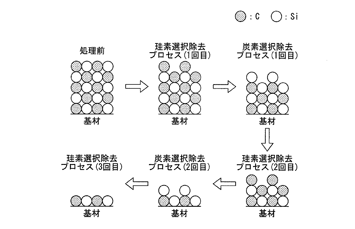
In the present invention, the removal of silicon carbide B is divided into silicon contained in silicon carbide B and carbon contained in silicon carbide B. As shown in FIG. 3, the silicon component contained in silicon carbide B is selectively removed by the fluorine-containing gas, and the carbon component contained in silicon carbide B is selectively removed by the oxygen-containing gas.
ここで、例えば、図4に示すように、フッ素含有ガスのみで炭化珪素Bの除去を行っていくと、珪素のみが除去されて炭素が残り、また、珪素も一様に除去することができない。
そこで、本発明では、一定の条件を設けて、フッ素含有ガスと、酸素含有ガスとを切り替えて炭化珪素Bの除去を行う。
Here, for example, as shown in FIG. 4, when silicon carbide B is removed only with a fluorine-containing gas, only silicon is removed, carbon remains, and silicon cannot be removed uniformly. .
Therefore, in the present invention, silicon carbide B is removed by switching between a fluorine-containing gas and an oxygen-containing gas under certain conditions.
図5は、本実施の形態の炭化珪素の除去方法を説明するためのフローチャートを示す図である。
次に、図1及び図5を参照して、本実施の形態の炭化珪素の除去方法について説明する。
始めに、STEP1では、図1に示す炭化珪素除去装置10の処理チャンバー11内に、炭化珪素Bが付着した炭化珪素形成装置の部材Aを収容する。その後、処理は、STEP2へと続く。
FIG. 5 is a flowchart for illustrating the silicon carbide removal method of the present embodiment.
Next, with reference to FIG. 1 and FIG. 5, the silicon carbide removal method of the present embodiment will be described.
First, in STEP1, the member A of the silicon carbide forming apparatus to which the silicon carbide B is adhered is accommodated in the
次いで、STEP2では、炭化珪素Bが付着した炭化珪素形成装置の部材Aに、プラズマ化させたフッ素含有ガスを供給することで、炭化珪素Bに含まれる珪素を選択的に除去する第1のステップを行なう。このとき、炭化珪素Bに含まれる珪素がフッ素含有ガスと反応して四フッ化珪素となり、脱離、除去される。 Next, in STEP 2, a first step of selectively removing silicon contained in silicon carbide B by supplying plasma-containing fluorine-containing gas to member A of the silicon carbide forming apparatus to which silicon carbide B is adhered. To do. At this time, silicon contained in silicon carbide B reacts with the fluorine-containing gas to form silicon tetrafluoride, which is desorbed and removed.
また、第1のステップは、処理チャンバー11から排出される排ガスである四フッ化珪素の濃度の時間変化を排ガス分析手段19で測定し、四フッ化珪素の濃度が最大値に到達後、5〜10測定時間区間で連続して四フッ化珪素の濃度がマイナスの変化となった段階で終了させる。その後、処理は、STEP3へと続く。
なお、四フッ化珪素の濃度が徐々に減少する理由としては、炭化珪素B表面の珪素が減少し、炭素が増加することで、その反応が妨げられるからである。
In the first step, the time change of the concentration of silicon tetrafluoride, which is the exhaust gas discharged from the
The reason why the concentration of silicon tetrafluoride is gradually decreased is that the reaction on the surface of silicon carbide B is reduced and the reaction is hindered by an increase in carbon.
次いで、STEP3では、炭化珪素Bが付着した炭化珪素形成装置の部材Aに、プラズマ化させた酸素含有ガスを供給することで、炭化珪素Bに含まれる炭素を選択的に除去する第2のステップを行なう。このとき、炭化珪素Bに含まれる炭素は、酸素含有ガスと反応して二酸化炭素となり、脱離、除去される。 Next, in STEP 3, a second step of selectively removing carbon contained in silicon carbide B by supplying plasma-containing oxygen-containing gas to member A of the silicon carbide forming apparatus to which silicon carbide B is adhered. To do. At this time, carbon contained in the silicon carbide B reacts with the oxygen-containing gas to become carbon dioxide, which is desorbed and removed.
また、第2のステップは、処理チャンバー11から排出される二酸化炭素の濃度の時間変化を排ガス分析手段19で測定し、二酸化炭素の濃度が最大値となった時点から5〜10測定時間区間で連続して二酸化炭素の濃度がマイナスの変化となった段階で終了させる。次いで、処理は、STEP4へと続く。
In the second step, the time change of the concentration of carbon dioxide discharged from the
なお、二酸化炭素の濃度が徐々に減少してくる理由としては、炭化珪素Bの表面の炭素が減少し、珪素が増加することで、その反応が妨げられるからである。
また、上記四フッ化珪素の濃度、及び二酸化炭素の濃度としては、移動平均等の算術処理を加えた値を用いるとよい。これにより、安定した濃度の挙動変化を掴むことが可能となる。
The reason why the concentration of carbon dioxide gradually decreases is that the carbon on the surface of silicon carbide B decreases and the reaction increases because silicon increases.
Further, as the concentration of silicon tetrafluoride and the concentration of carbon dioxide, values obtained by adding arithmetic processing such as moving average may be used. Thereby, it becomes possible to grasp the behavior change of the stable density | concentration.
次いで、STEP4では、第1及び第2のステップの処理後に、処理チャンバー11から排出される四フッ化珪素の濃度が、予め設定した閾値以下になったか否かの判定が行なわれる。
STEP4において、四フッ化珪素の濃度が、予め設定した閾値以下になったと肯定判定(Yesと判定)された場合、図5に示す処理は終了する。また、STEP4において、四フッ化珪素の濃度が、予め設定した閾値以下になっていない否定判定(Noと判定)された場合、処理は、STEP2に戻り、第1及び第2のステップの処理(STEP2,3の処理)が行なわれ、再度、STEP4へと処理が進む。
Next, in STEP 4, it is determined whether or not the concentration of silicon tetrafluoride discharged from the
In STEP 4, when it is determined that the concentration of silicon tetrafluoride is equal to or lower than a preset threshold value (determined as Yes), the process illustrated in FIG. 5 ends. In STEP 4, when the negative determination (determination of No) that the concentration of silicon tetrafluoride is not lower than the preset threshold value is made, the process returns to STEP 2, and the process of the first and second steps ( Steps 2 and 3 are performed), and the process proceeds to STEP 4 again.
つまり、STEP4において、肯定判定されるまで、第1及び第2のステップの処理を繰り返し行なうことで、炭化珪素Bに含まれる珪素の除去、及び炭化珪素Bに含まれる炭素の除去を繰り返し行う。言い換えれば、第1及び第2のステップを繰り返し行うことで、炭化珪素形成装置の部材Aに付着した炭化珪素Bの除去を行なう。 That is, in STEP 4, the first and second steps are repeatedly performed until an affirmative determination is made, thereby repeatedly removing silicon contained in silicon carbide B and removing carbon contained in silicon carbide B. In other words, the silicon carbide B adhering to the member A of the silicon carbide forming apparatus is removed by repeating the first and second steps.
ところで、炭化珪素Bの除去が終了に近づくと、第1のステップで発生する四フッ化珪素の濃度、及び第2のステップで発生する二酸化炭素の濃度が徐々に減少する。
そこで、上記STEP4で説明したように、四フッ化珪素の濃度が予め設定した閾値以下になった際に、第1及び第2のステップの処理を終了することで、炭化珪素形成装置の部材Aにダメージを与えることなく、炭化珪素形成装置の部材Aに付着した炭化珪素Bを精度よく除去することができる。
By the way, when the removal of silicon carbide B approaches the end, the concentration of silicon tetrafluoride generated in the first step and the concentration of carbon dioxide generated in the second step gradually decrease.
Therefore, as described in STEP 4 above, when the concentration of silicon tetrafluoride is equal to or lower than a preset threshold value, the processing of the first and second steps is terminated, whereby the member A of the silicon carbide forming apparatus is completed. The silicon carbide B adhering to the member A of the silicon carbide forming apparatus can be accurately removed without damaging the substrate.
また、四フッ化珪素の濃度の上記閾値(予め設定した閾値)としては、例えば、第1のステップで検出される四フッ化珪素の濃度の最大値に対して、四フッ化珪素の濃度が1/10以下の値を用いることができる。
また、四フッ化珪素の濃度の上記閾値は、予め、一定量の炭化珪素量と除去処理速度の関係(第1のステップの四フッ化珪素の濃度の最大値と、第1及び第2のステップを繰り返し行った際の四フッ化珪素の濃度の関係)を把握した上で、初期段階の炭化珪素の量と目標とする炭化珪素の除去処理量に応じて任意に設定することができる。
Further, as the above-mentioned threshold value of the concentration of silicon tetrafluoride (a preset threshold value), for example, the concentration of silicon tetrafluoride is higher than the maximum value of the concentration of silicon tetrafluoride detected in the first step. A value of 1/10 or less can be used.
Further, the threshold value of the silicon tetrafluoride concentration is determined in advance by the relationship between the silicon carbide amount of a certain amount and the removal processing speed (the maximum value of the silicon tetrafluoride concentration in the first step, the first and second values). It can be arbitrarily set according to the amount of silicon carbide in the initial stage and the target silicon carbide removal processing amount after grasping the relationship between the concentration of silicon tetrafluoride when the steps are repeated.
また、上記四フッ化珪素の濃度の閾値は、予め図1に示す制御手段21(具体的には、記憶部(図示せず))に格納されており、制御手段21内において、排ガス分析手段19が検出する四フッ化珪素の濃度と、上記四フッ化珪素の濃度の閾値との比較が行なわれ、この結果に基づいて、制御手段21は処理チャンバー11、フッ素含有ガス供給手段13、酸素含有ガス供給手段14、及びプラズマ発生手段15の制御を行なう。
Further, the threshold value of the concentration of silicon tetrafluoride is stored in advance in the control means 21 (specifically, a storage unit (not shown)) shown in FIG. A comparison is made between the concentration of silicon tetrafluoride detected by 19 and the threshold value of the concentration of silicon tetrafluoride. Based on this result, the control means 21 performs processing
なお、図5では、STEP4において、四フッ化珪素の濃度が閾値以下になったか否かの判定を行なう場合を例に挙げて説明したが、STEP4において、二酸化炭素の濃度が閾値以下になったか否かの判定を行なってもよい。この場合、STEP4において、四フッ化珪素の濃度が閾値以下になったか否かの判定を行なう場合と同様な効果を得ることができる。 In FIG. 5, the case where it is determined whether or not the concentration of silicon tetrafluoride is equal to or lower than the threshold value in STEP 4 is described as an example. It may be determined whether or not. In this case, it is possible to obtain the same effect as in STEP 4 in which it is determined whether or not the concentration of silicon tetrafluoride is equal to or lower than the threshold value.
また、上記四フッ化珪素及び二酸化炭素の濃度を測定する排ガス分析手段19としては、非分散式赤外線式分析計を用いるとよい。
このように、四フッ化珪素及び二酸化炭素の濃度を測定する排ガス分析手段19として非分散式赤外線式分析計を用いることで、1つのデータの採取に要する時間が、短い場合には数秒、長くても数十秒となるため、データの採取時間が短い場合には10測定時間区間、データの採取時間が長い場合には5測定区間の応答時間を設けることで効率よく炭化珪素Bの除去処理を行なうことができる。
Further, as the exhaust gas analyzing means 19 for measuring the concentrations of silicon tetrafluoride and carbon dioxide, a non-dispersive infrared analyzer may be used.
In this way, by using a non-dispersive infrared analyzer as the exhaust gas analyzing means 19 for measuring the concentrations of silicon tetrafluoride and carbon dioxide, the time required for collecting one data is several seconds longer if it is short. Since it takes several tens of seconds, it is possible to efficiently remove silicon carbide B by providing a response time of 10 measurement time intervals when the data collection time is short and 5 measurement intervals when the data collection time is long. Can be performed.
なお、本実施の形態では、炭化珪素Bから発生する成分を四フッ化珪素と二酸化炭素とに特定したが、これは、1つには、四フッ化珪素及び二酸化炭素が、その発生物の大部分を占めるからである。
また、もう1つの理由としては、四フッ化珪素及び二酸化炭素が、主に発生するための除去反応条件が、フッ素含有ガス成分の濃度が低く、加熱温度も低く設定でき、かつ、本実施の形態の炭化珪素除去装置10で炭化珪素Bの除去を行なうことで、良好な除去性能を得ることができるからである。
In the present embodiment, the components generated from silicon carbide B are specified as silicon tetrafluoride and carbon dioxide. However, one of the components is silicon tetrafluoride and carbon dioxide. Because it occupies most.
Another reason is that the removal reaction conditions for mainly generating silicon tetrafluoride and carbon dioxide are such that the concentration of the fluorine-containing gas component is low and the heating temperature can be set low. This is because good removal performance can be obtained by removing the silicon carbide B with the silicon
但し、例えば、炭化珪素Bとフッ素含有ガスとの反応により、四フッ化炭素も相当量発生する場合は、炭化珪素起因の炭素として、二酸化炭素に四フッ化珪素も加えて終点検出、及び終点検出の制御機構を調整することで、より高性能の炭化珪素除去装置を得ることができると共に、より高精度の炭化珪素Bの除去を行なうことができる。 However, for example, when a considerable amount of carbon tetrafluoride is generated by the reaction between silicon carbide B and a fluorine-containing gas, carbon tetrafluoride is added to carbon dioxide as carbon derived from silicon carbide, and endpoint detection is performed. By adjusting the detection control mechanism, it is possible to obtain a silicon carbide removing device with higher performance and to remove silicon carbide B with higher accuracy.
本実施の形態の炭化珪素の除去方法によれば、炭化珪素Bが付着した炭化珪素形成装置の部材Aを収容する処理チャンバー11内に、プラズマ化させたフッ素含有ガスを供給することで、炭化珪素Bに含まれる珪素を除去する第1のステップと、処理チャンバー11内に、プラズマ化させた酸素含有ガスを供給することで、炭化珪素Bに含まれる炭素を除去する第2のステップと、を交互に行なうことにより、炭化珪素Bに含まれる炭素及び珪素を精度よく除去できる。
According to the silicon carbide removal method of the present embodiment, carbonized carbon is supplied by supplying the plasma-containing fluorine-containing gas into the
また、先に説明した本実施の形態の変形例に係る炭化珪素除去装置25を用いて炭化珪素Bの除去を行なう場合、図5で説明した本実施の形態の炭化珪素の除去方法と同様な手法により、炭化珪素Bの除去を行なうことができる。
さらに、図1及び図2に示す炭化珪素除去装置10,25を炭化珪素形成装置(図示せず)に適用してもよい。
When silicon carbide B is removed using silicon
Further, silicon
以上、本発明の好ましい実施の形態について詳述したが、本発明はかかる特定の実施の形態に限定されるものではなく、特許請求の範囲内に記載された本発明の要旨の範囲内において、種々の変形・変更が可能である。 The preferred embodiments of the present invention have been described in detail above, but the present invention is not limited to such specific embodiments, and within the scope of the present invention described in the claims, Various modifications and changes are possible.
(試験例1)
図1に示す炭化珪素除去装置10を用いて、炭化珪素の除去試験を行った。具体的には、処理チャンバー11内に炭化珪素基板(縦10mm×横10mm×厚さ0.75mm)を配置し、該炭化珪素基板を400℃の温度に加熱保持した。
( Test Example 1)
A silicon carbide removal test was performed using the silicon
第1のステップでは、フッ素(100sccm)にアルゴン(500sccm)を添加したガスをクリーニングガス(フッ素含有ガス)として使用した。また、第1のステップでは、高周波印加電力を1000W(2.56GHz)、処理チャンバー11内の圧力を2torr、処理時間を3分間とした。
In the first step, a gas obtained by adding argon (500 sccm) to fluorine (100 sccm) was used as a cleaning gas (fluorine-containing gas). In the first step, the high frequency applied power was 1000 W (2.56 GHz), the pressure in the
第2のステップでは、酸素(700sccm)に、フッ素(100sccm)及びアルゴン(100sccm)を添加したガスをクリーニングガス(酸素含有ガス)として使用した。また、第2のステップでは、高周波印加電力を1000W(2.56GHz)、処理チャンバー11内の圧力を1torr、処理時間を3分間とした。
In the second step, a gas obtained by adding fluorine (100 sccm) and argon (100 sccm) to oxygen (700 sccm) was used as a cleaning gas (oxygen-containing gas). In the second step, the high frequency applied power was 1000 W (2.56 GHz), the pressure in the
第1及び第2のステップをそれぞれ一回ずつ行い、第1及び第2のステップのそれぞれのプロセス中における四フッ化珪素の濃度及び二酸化炭素の濃度と、各ステップ終了後の膜厚の変化量(実測値)と、各ステップ終了後の膜厚の変化量(排ガスの濃度から算出した計測値)と、膜厚変化比(膜厚変化量の実測値/膜厚変化量の計算値)と、を取得した。 Each of the first and second steps is performed once, and the concentration of silicon tetrafluoride and carbon dioxide in each process of the first and second steps, and the amount of change in film thickness after the completion of each step. (Actual measurement value), film thickness change amount after each step (measured value calculated from exhaust gas concentration), film thickness change ratio (actual film thickness change value / calculated film thickness change value), , Got.
表1に、試験例1の第1のステップの結果を示す。また、表2に、試験例1の第2のステップの結果を示す。なお、膜厚の変化量の実測には、レーザマイクロスコープを使用した。 Table 1 shows the result of the first step of Test Example 1. Table 2 shows the result of the second step of Test Example 1. Note that a laser microscope was used to actually measure the amount of change in film thickness.
(参考例1)
上記試験例1で使用した炭化珪素基板の替わりに、珪素基板(縦10mm×横10mm×厚さ0.75mm)、及び炭素基板(縦10mm×横10mm×厚さ0.75mm)を用いて、試験例1と同様な実験を行い、データを取得した。
参考例1(珪素基板及び炭素基板)の第1のステップの処理を行なった際のデータを表1に示す。また、参考例1(珪素基板及び炭素基板)の第2のステップの処理を行なった際のデータを表2に示す。
(Reference Example 1)
Instead of the silicon carbide substrate used in Test Example 1, using a silicon substrate (vertical 10 mm ×
Table 1 shows data obtained when the first step of Reference Example 1 (silicon substrate and carbon substrate) was performed. Table 2 shows data obtained when the second step of Reference Example 1 (silicon substrate and carbon substrate) was performed.
(表1及び表2の結果について)
表1及び表2を参照するに、珪素(Si)は、第1のステップで使用するフッ素含有ガス(クリーニングガス)で多く除去され、また、炭素(C)は第2のステップで使用する酸素含有ガス(クリーニングガス)で多く除去されることが確認できた。
(About the results of Table 1 and Table 2)
Referring to Table 1 and Table 2, silicon (Si) is largely removed by the fluorine-containing gas (cleaning gas) used in the first step, and carbon (C) is oxygen used in the second step. It was confirmed that a large amount of the contained gas (cleaning gas) was removed.
また、表1及び表2を参照するに、炭化珪素(SiC)は、第1及び第2のステップのどちらでも除去されたが、排ガス濃度から推定した膜厚には至っていなかった。
これは、第1のステップの場合、炭化珪素基板の表面の珪素だけではなく、炭化珪素基板の表面よりも内側(内部)の珪素とも反応して四フッ化珪素となって脱離するが、炭化珪素の表面の炭素は脱離せずにそのまま残留することに起因すると推測される。
Further, referring to Tables 1 and 2, silicon carbide (SiC) was removed in both the first and second steps, but the film thickness estimated from the exhaust gas concentration was not reached.
In the case of the first step, this is not only silicon on the surface of the silicon carbide substrate but also silicon (inside) silicon than the surface of the silicon carbide substrate, which reacts with silicon tetrafluoride and desorbs. It is presumed that the carbon on the surface of silicon carbide remains as it is without desorption.
実際に、例えば、第1のステップ後の珪素と炭素の原子数比を、炭化珪素基板の表面、中間、裏面上で蛍光X線分析により測定したところ、表面が(Si:C=40.7:59.3)、中間が(Si:C=37.0:63.0)、裏面が(Si:C=48.6:51.4)であった。このことから、珪素の脱離は、内部まで至っているが、表層は炭素が残留していることが確認できた。これが、膜厚を厚くしている理由と考えられる。 Actually, for example, when the atomic ratio of silicon and carbon after the first step is measured by X-ray fluorescence analysis on the surface, middle, and back surface of the silicon carbide substrate, the surface is (Si: C = 40.7). : 59.3), the middle was (Si: C = 37.0: 63.0), and the back surface was (Si: C = 48.6: 51.4). From this, it was confirmed that although the silicon desorption had reached the inside, carbon remained in the surface layer. This is considered to be the reason why the film thickness is increased.
(試験例2)
先に説明した試験例1及び参考例1の結果から、炭化珪素を効率良く除去するためには、珪素を除去する第1のステップと、炭素を除去する第2のステップと、を組み合わせていく必要があることが確認できた。
( Test Example 2)
From the results of Test Example 1 and Reference Example 1 described above, in order to efficiently remove silicon carbide, the first step for removing silicon and the second step for removing carbon are combined. It was confirmed that it was necessary.
そこで、試験例2では、試験例1で説明した条件を用いて、第1のステップと、第2のステップと、を交互に2回ずつ実施し、第1及び第2のステップのプロセス中における四フッ化珪素の濃度及び二酸化炭素の濃度を測定すると共に、第1及び第2のステップ終了後の膜厚の変化量を求めた。この結果を、表3に示す。 Therefore, in Test Example 2, the first step and the second step are alternately performed twice using the conditions described in Test Example 1, and the first and second steps are in the process. While measuring the density | concentration of silicon tetrafluoride and the density | concentration of a carbon dioxide, the variation | change_quantity of the film thickness after the 1st and 2nd step completion | finish was calculated | required. The results are shown in Table 3.
(参考例2)
参考例2として、炭化珪素基板を用いて第1のステップ(試験例1と同じ条件)のみを4回行なって、第1のステップのプロセス中における四フッ化珪素の濃度及び二酸化炭素の濃度を測定すると共に、第1のステップが4回終了した後の膜厚の変化量を求めた。この結果を、表4に示す。
(Reference Example 2)
As Reference Example 2, only the first step (same conditions as in Test Example 1) was performed four times using a silicon carbide substrate, and the concentrations of silicon tetrafluoride and carbon dioxide in the process of the first step were determined. While measuring, the amount of change in film thickness after the first step was completed four times was determined. The results are shown in Table 4.
また、炭化珪素基板を用いて第2のステップのみを4回行なって、第2のステップ(試験例1と同じ条件)のプロセス中における四フッ化珪素の濃度及び二酸化炭素の濃度を測定すると共に、第2のステップが4回終了した後の膜厚の変化量を求めた。この結果を、表5に示す。 Further, only the second step is performed four times using the silicon carbide substrate, and the concentration of silicon tetrafluoride and the concentration of carbon dioxide in the process of the second step (same conditions as in Test Example 1) are measured. The amount of change in film thickness after the second step was completed four times was determined. The results are shown in Table 5.
(表3〜表5の結果について)
表3〜表5を参照するに、第1のステップと第2のステップとを交互に組み合わせた場合が最も多く炭化珪素が除去できることが確認できた。
また、上記除去処理後の炭化珪素基板の表面、中間、裏面に存在する珪素と炭素との原子数比を測定したところ、表面が(Si:C=48.1:51.9)、中間が(Si:C=48.5:51.5)、裏面が(Si:C=49.6:50.4)であった。この結果から、炭化珪素に含まれる炭素及び珪素を精度よく除去できたことが確認できた。
(About the results of Tables 3 to 5)
Referring to Tables 3 to 5, it was confirmed that silicon carbide can be removed most frequently when the first step and the second step are alternately combined.
Further, when the atomic ratio of silicon and carbon existing on the surface, middle, and back surface of the silicon carbide substrate after the above removal treatment was measured, the surface was (Si: C = 48.1: 51.9), and the middle was (Si: C = 48.5: 51.5) and the back surface was (Si: C = 49.6: 50.4). From this result, it was confirmed that carbon and silicon contained in silicon carbide could be removed with high accuracy.
(試験例3)
第1のステップ(試験例1と同じ条件)と第2のステップ(試験例1と同じ条件)とを交互に行い、排ガス中炭化珪素が75μm程度堆積した部材を90%以上(炭化珪素の厚さが7.5μm以下)除去する処理を行ない、排ガス中に含まれる四フッ化珪素の濃度及び二酸化炭素の濃度を測定した。この結果を図6に示す。
( Test Example 3)
The first step (same conditions as in Test Example 1) and the second step (same conditions as in Test Example 1) are alternately performed, and 90% or more of the members in which about 75 μm of silicon carbide in exhaust gas is deposited (thickness of silicon carbide) And the concentration of silicon tetrafluoride and the concentration of carbon dioxide contained in the exhaust gas were measured. The result is shown in FIG.
図6は、第1及び第2のステップを交互に行なった際の、排ガス中の四フッ化珪素の濃度と二酸化炭素の濃度との経時変化を示す図である。
ここでの閾値としては、これとは別の評価において取得された二酸化炭素の排ガス濃度が10ppm以下という値を採用した。この閾値は、炭化珪素の膜厚が10μm程度堆積した部材を第2のステップで除去処理した場合の二酸化炭素の濃度の挙動から決定した値である。
FIG. 6 is a diagram showing temporal changes in the concentration of silicon tetrafluoride and the concentration of carbon dioxide in the exhaust gas when the first and second steps are alternately performed.
As the threshold value here, a value that the exhaust gas concentration of carbon dioxide obtained in another evaluation was 10 ppm or less was adopted. This threshold value is a value determined from the behavior of the concentration of carbon dioxide when a member having a silicon carbide film thickness of about 10 μm is removed in the second step.
図6に示すように、第1のステップの3回目まで通常通り処理を行い、第2のステップの3回目において、このステップにおける二酸化炭素の濃度の最大値58ppmを検出してから閾値(二酸化炭素の濃度10ppm)以下に到達した後、処理を終了した。
処理終了後に、炭化珪素の実際の膜厚を測定した結果、7.1μmであった。また、この最表面の炭化珪素の珪素と炭素の原子数比を蛍光X線分析により測定したところ、表面は(Si:C=47.9:52.1)であり、炭化珪素を精度よく除去できることが確認できた。
As shown in FIG. 6, the process is normally performed until the third time of the first step, and in the third time of the second step, the maximum value 58 ppm of the carbon dioxide concentration in this step is detected and then the threshold value (carbon dioxide After reaching a concentration of 10 ppm or less, the treatment was terminated.
After the treatment, the actual film thickness of silicon carbide was measured and found to be 7.1 μm. Further, when the atomic ratio of silicon to carbon in the silicon carbide on the outermost surface was measured by fluorescent X-ray analysis, the surface was (Si: C = 47.9: 52.1), and silicon carbide was removed with high precision. I was able to confirm that it was possible.
本発明は、炭化珪素に含まれる炭素成分及び珪素成分を精度よく除去可能な炭化珪素除去装置、及び炭化珪素の除去方法に適用可能である。 The present invention is applicable to a silicon carbide removing device and a silicon carbide removing method capable of accurately removing a carbon component and a silicon component contained in silicon carbide.
10,25…炭化珪素除去装置、11…処理チャンバー、13…フッ素含有ガス供給手段、14…酸素含有ガス供給手段、15…プラズマ発生手段、16…真空ポンプ、17…ガス管、19…排ガス分析手段、21…制御手段
DESCRIPTION OF
Claims (4)
前記炭化珪素が付着した前記炭化珪素形成装置の部材を収容する処理チャンバー内に、プラズマ化させたフッ素含有ガスを供給することで、前記炭化珪素に含まれる珪素を除去する第1のステップと、
前記処理チャンバー内に、プラズマ化させた酸素含有ガスを供給することで、前記炭化珪素に含まれる炭素を除去する第2のステップと、を含み、
前記第1のステップと、前記第2のステップと、を交互に行ない、
前記処理チャンバー内の排ガスのうち、四フッ化珪素の濃度の時間変化を測定し、前記四フッ化珪素の濃度が最大値に到達後、5〜10測定時間区間で連続して前記四フッ化珪素の濃度がマイナスの変化となった段階で、前記第1のステップを終了させ、
前記処理チャンバー内の排ガスのうち、二酸化炭素の濃度の時間変化を測定し、前記二酸化炭素の濃度が最大値に到達後、5〜10測定時間区間で連続して前記二酸化炭素の濃度がマイナスの変化となった段階で、前記第2のステップを終了させることを特徴とする炭化珪素の除去方法。 A silicon carbide removing method for removing silicon carbide adhering to a member of a silicon carbide forming device,
A first step of removing silicon contained in the silicon carbide by supplying a plasma-containing fluorine-containing gas into a processing chamber containing a member of the silicon carbide forming apparatus to which the silicon carbide has adhered;
A second step of removing carbon contained in the silicon carbide by supplying a plasma-containing oxygen-containing gas into the processing chamber;
Said first step, alternating rows that have a said second step,
Of the exhaust gas in the processing chamber, the time change of the concentration of silicon tetrafluoride is measured, and after the concentration of the silicon tetrafluoride reaches the maximum value, the tetrafluoride is continuously generated for 5 to 10 measurement time intervals. When the silicon concentration is negatively changed, the first step is terminated,
Of the exhaust gas in the processing chamber, the time change of the carbon dioxide concentration is measured, and after the carbon dioxide concentration reaches the maximum value, the carbon dioxide concentration is negative continuously for 5 to 10 measurement time intervals. The method of removing silicon carbide , wherein the second step is terminated at the stage of change .
Priority Applications (1)
| Application Number | Priority Date | Filing Date | Title |
|---|---|---|---|
| JP2011045239A JP5643679B2 (en) | 2011-03-02 | 2011-03-02 | Method for removing silicon carbide |
Applications Claiming Priority (1)
| Application Number | Priority Date | Filing Date | Title |
|---|---|---|---|
| JP2011045239A JP5643679B2 (en) | 2011-03-02 | 2011-03-02 | Method for removing silicon carbide |
Publications (2)
| Publication Number | Publication Date |
|---|---|
| JP2012182373A JP2012182373A (en) | 2012-09-20 |
| JP5643679B2 true JP5643679B2 (en) | 2014-12-17 |
Family
ID=47013310
Family Applications (1)
| Application Number | Title | Priority Date | Filing Date |
|---|---|---|---|
| JP2011045239A Active JP5643679B2 (en) | 2011-03-02 | 2011-03-02 | Method for removing silicon carbide |
Country Status (1)
| Country | Link |
|---|---|
| JP (1) | JP5643679B2 (en) |
Families Citing this family (10)
| Publication number | Priority date | Publication date | Assignee | Title |
|---|---|---|---|---|
| JP5465802B2 (en) * | 2013-04-12 | 2014-04-09 | 東京エレクトロン株式会社 | Thin film forming apparatus cleaning method, thin film forming method, thin film forming apparatus, and program |
| US10297442B2 (en) * | 2013-05-31 | 2019-05-21 | Lam Research Corporation | Remote plasma based deposition of graded or multi-layered silicon carbide film |
| JP2015018876A (en) * | 2013-07-09 | 2015-01-29 | 株式会社アルバック | Conditioning method of reaction apparatus |
| JP6172669B2 (en) * | 2013-08-22 | 2017-08-02 | 大陽日酸株式会社 | Susceptor and susceptor cleaning method |
| JP6232680B2 (en) * | 2013-09-06 | 2017-11-22 | 大陽日酸株式会社 | How to clean the susceptor |
| JP6309833B2 (en) * | 2014-06-18 | 2018-04-11 | 大陽日酸株式会社 | Silicon carbide removal device |
| JP6339423B2 (en) * | 2014-06-19 | 2018-06-06 | 大陽日酸株式会社 | Method for cleaning components of semiconductor manufacturing equipment |
| JP6541257B2 (en) * | 2015-06-22 | 2019-07-10 | 昭和電工株式会社 | Method of cleaning a silicon carbide film deposition apparatus |
| KR102490700B1 (en) * | 2017-03-27 | 2023-01-26 | 주식회사 히타치하이테크 | Plasma treatment method |
| CN116779423B (en) * | 2023-08-24 | 2024-02-23 | 粤芯半导体技术股份有限公司 | Wafer control recycling method and silicon wafer |
Family Cites Families (11)
| Publication number | Priority date | Publication date | Assignee | Title |
|---|---|---|---|---|
| JPS57124438A (en) * | 1981-01-26 | 1982-08-03 | Rikagaku Kenkyusho | Ion beam etching for silicon carbide |
| JPH0697075A (en) * | 1992-09-14 | 1994-04-08 | Toshiba Corp | Plasma cleaning of thin film deposition chamber |
| JP3457457B2 (en) * | 1996-03-15 | 2003-10-20 | 株式会社東芝 | Charged beam device with cleaning function |
| JP2001250785A (en) * | 2000-03-06 | 2001-09-14 | Toshiba Ceramics Co Ltd | Washing method of member for semiconductor heat treatment covered with silicon carbide |
| JP2002217166A (en) * | 2001-01-19 | 2002-08-02 | Toshiba Corp | Cleaning method of gas processing equipment |
| JP4801709B2 (en) * | 2003-03-14 | 2011-10-26 | キヤノンアネルバ株式会社 | Film forming method using CVD apparatus |
| JP2004335789A (en) * | 2003-05-08 | 2004-11-25 | Tadahiro Omi | Cleaning method of substrate processing equipment |
| US20060021633A1 (en) * | 2004-07-27 | 2006-02-02 | Applied Materials, Inc. | Closed loop clean gas control |
| JP2006086325A (en) * | 2004-09-16 | 2006-03-30 | Tokyo Electron Ltd | End point detecting method of cleaning |
| JP5011148B2 (en) * | 2008-02-06 | 2012-08-29 | 大陽日酸株式会社 | Semiconductor device manufacturing method, cleaning method, and substrate processing apparatus |
| JP5281363B2 (en) * | 2008-10-31 | 2013-09-04 | 株式会社堀場製作所 | Material gas concentration control system |
-
2011
- 2011-03-02 JP JP2011045239A patent/JP5643679B2/en active Active
Also Published As
| Publication number | Publication date |
|---|---|
| JP2012182373A (en) | 2012-09-20 |
Similar Documents
| Publication | Publication Date | Title |
|---|---|---|
| JP5643679B2 (en) | Method for removing silicon carbide | |
| JP5705495B2 (en) | Plasma processing method and plasma processing apparatus | |
| CN102856191B (en) | Plasma processing method | |
| JP2007531996A5 (en) | ||
| JP5933347B2 (en) | Silicon carbide removal method | |
| TWI674627B (en) | Plasma processing method | |
| JP2007531288A (en) | Remote chamber method for removing surface deposits | |
| JP5973850B2 (en) | Cleaning end point detection method | |
| JP5763477B2 (en) | Silicon carbide film forming apparatus and silicon carbide removing method | |
| JP2007158230A (en) | Cleaning method for plasma etching equipment and plasma etching equipment | |
| JP2015037134A (en) | Silicon carbide removal device and silicon carbide removal method | |
| JP2008091882A (en) | Detection of endpoint of cleaning process | |
| JP5214316B2 (en) | Cleaning method of plasma film forming apparatus | |
| JP6843069B2 (en) | Determining Insitu Etching Rate for Chamber Cleaning End Point | |
| CN102024683B (en) | Method for judging whether to start processing | |
| JP2009065169A (en) | Quantification of hydrophobic, and hydrophilic properties of materials | |
| TWI765397B (en) | Optical absorption sensor for semiconductor processing | |
| Sitanov et al. | Kinetics of atomic recombination on silicon samples in chlorine plasma | |
| Efremov et al. | Plasma parameters and etching mechanisms of metals and semiconductors in hydrogen chloride | |
| JP5904877B2 (en) | Silicon carbide removal method | |
| KR20220095494A (en) | Method of detecting an end point of an in-situ dry cleaning process | |
| JP2004266077A (en) | Method of cleaning cvd chamber and cleaning gas used therefor | |
| JP6309833B2 (en) | Silicon carbide removal device | |
| JP4961064B2 (en) | Process and vacuum processing reactor apparatus for dry etching | |
| JP2013251325A (en) | Silicon carbide removing device and method for removing silicon carbide |
Legal Events
| Date | Code | Title | Description |
|---|---|---|---|
| A621 | Written request for application examination |
Free format text: JAPANESE INTERMEDIATE CODE: A621 Effective date: 20131025 |
|
| A977 | Report on retrieval |
Free format text: JAPANESE INTERMEDIATE CODE: A971007 Effective date: 20140417 |
|
| A131 | Notification of reasons for refusal |
Free format text: JAPANESE INTERMEDIATE CODE: A131 Effective date: 20140729 |
|
| A521 | Request for written amendment filed |
Free format text: JAPANESE INTERMEDIATE CODE: A523 Effective date: 20140926 |
|
| TRDD | Decision of grant or rejection written | ||
| A01 | Written decision to grant a patent or to grant a registration (utility model) |
Free format text: JAPANESE INTERMEDIATE CODE: A01 Effective date: 20141021 |
|
| A61 | First payment of annual fees (during grant procedure) |
Free format text: JAPANESE INTERMEDIATE CODE: A61 Effective date: 20141031 |
|
| R150 | Certificate of patent or registration of utility model |
Ref document number: 5643679 Country of ref document: JP Free format text: JAPANESE INTERMEDIATE CODE: R150 |
|
| R250 | Receipt of annual fees |
Free format text: JAPANESE INTERMEDIATE CODE: R250 |
|
| R250 | Receipt of annual fees |
Free format text: JAPANESE INTERMEDIATE CODE: R250 |
|
| R250 | Receipt of annual fees |
Free format text: JAPANESE INTERMEDIATE CODE: R250 |
|
| R250 | Receipt of annual fees |
Free format text: JAPANESE INTERMEDIATE CODE: R250 |
|
| S111 | Request for change of ownership or part of ownership |
Free format text: JAPANESE INTERMEDIATE CODE: R313111 |
|
| R350 | Written notification of registration of transfer |
Free format text: JAPANESE INTERMEDIATE CODE: R350 |
|
| R250 | Receipt of annual fees |
Free format text: JAPANESE INTERMEDIATE CODE: R250 |
|
| R250 | Receipt of annual fees |
Free format text: JAPANESE INTERMEDIATE CODE: R250 |
|
| R250 | Receipt of annual fees |
Free format text: JAPANESE INTERMEDIATE CODE: R250 |