JP5632007B2 - Device for reducing axial contraction of catheter or sheath due to repeated bending - Google Patents
Device for reducing axial contraction of catheter or sheath due to repeated bending Download PDFInfo
- Publication number
- JP5632007B2 JP5632007B2 JP2012537882A JP2012537882A JP5632007B2 JP 5632007 B2 JP5632007 B2 JP 5632007B2 JP 2012537882 A JP2012537882 A JP 2012537882A JP 2012537882 A JP2012537882 A JP 2012537882A JP 5632007 B2 JP5632007 B2 JP 5632007B2
- Authority
- JP
- Japan
- Prior art keywords
- strut
- core
- bendable
- slots
- catheter
- Prior art date
- Legal status (The legal status is an assumption and is not a legal conclusion. Google has not performed a legal analysis and makes no representation as to the accuracy of the status listed.)
- Active
Links
- 238000005452 bending Methods 0.000 title claims description 45
- 230000008602 contraction Effects 0.000 title claims description 7
- 239000000463 material Substances 0.000 claims description 26
- 229910001000 nickel titanium Inorganic materials 0.000 claims description 17
- 230000004323 axial length Effects 0.000 claims description 13
- HLXZNVUGXRDIFK-UHFFFAOYSA-N nickel titanium Chemical compound [Ti].[Ti].[Ti].[Ti].[Ti].[Ti].[Ti].[Ti].[Ti].[Ti].[Ti].[Ni].[Ni].[Ni].[Ni].[Ni].[Ni].[Ni].[Ni].[Ni].[Ni].[Ni].[Ni].[Ni].[Ni] HLXZNVUGXRDIFK-UHFFFAOYSA-N 0.000 claims description 11
- 239000004696 Poly ether ether ketone Substances 0.000 claims description 10
- 229920002530 polyetherether ketone Polymers 0.000 claims description 10
- 239000010935 stainless steel Substances 0.000 claims description 9
- PXHVJJICTQNCMI-UHFFFAOYSA-N Nickel Chemical compound [Ni] PXHVJJICTQNCMI-UHFFFAOYSA-N 0.000 claims description 8
- 239000004642 Polyimide Substances 0.000 claims description 7
- 229920001721 polyimide Polymers 0.000 claims description 7
- 229920001343 polytetrafluoroethylene Polymers 0.000 claims description 6
- 239000004810 polytetrafluoroethylene Substances 0.000 claims description 6
- 239000004952 Polyamide Substances 0.000 claims description 4
- 229920002647 polyamide Polymers 0.000 claims description 4
- 230000004044 response Effects 0.000 claims description 2
- 230000000149 penetrating effect Effects 0.000 claims 2
- 229910000990 Ni alloy Inorganic materials 0.000 claims 1
- 229910001069 Ti alloy Inorganic materials 0.000 claims 1
- 229910001256 stainless steel alloy Inorganic materials 0.000 claims 1
- 238000000034 method Methods 0.000 description 20
- 238000004519 manufacturing process Methods 0.000 description 14
- 229910001220 stainless steel Inorganic materials 0.000 description 8
- 230000008901 benefit Effects 0.000 description 5
- 239000000306 component Substances 0.000 description 4
- 230000007246 mechanism Effects 0.000 description 4
- -1 polytetrafluoroethylene Polymers 0.000 description 4
- 206010003658 Atrial Fibrillation Diseases 0.000 description 3
- 239000004677 Nylon Substances 0.000 description 3
- 229920002614 Polyether block amide Polymers 0.000 description 3
- 229920006362 Teflon® Polymers 0.000 description 3
- HZEWFHLRYVTOIW-UHFFFAOYSA-N [Ti].[Ni] Chemical compound [Ti].[Ni] HZEWFHLRYVTOIW-UHFFFAOYSA-N 0.000 description 3
- JUPQTSLXMOCDHR-UHFFFAOYSA-N benzene-1,4-diol;bis(4-fluorophenyl)methanone Chemical compound OC1=CC=C(O)C=C1.C1=CC(F)=CC=C1C(=O)C1=CC=C(F)C=C1 JUPQTSLXMOCDHR-UHFFFAOYSA-N 0.000 description 3
- 239000000560 biocompatible material Substances 0.000 description 3
- 230000036760 body temperature Effects 0.000 description 3
- 230000033001 locomotion Effects 0.000 description 3
- 238000013507 mapping Methods 0.000 description 3
- 239000007769 metal material Substances 0.000 description 3
- 229910052759 nickel Inorganic materials 0.000 description 3
- 229920001778 nylon Polymers 0.000 description 3
- 239000012815 thermoplastic material Substances 0.000 description 3
- XLYOFNOQVPJJNP-UHFFFAOYSA-N water Substances O XLYOFNOQVPJJNP-UHFFFAOYSA-N 0.000 description 3
- 229920000271 Kevlar® Polymers 0.000 description 2
- 239000004809 Teflon Substances 0.000 description 2
- 229910045601 alloy Inorganic materials 0.000 description 2
- 239000000956 alloy Substances 0.000 description 2
- 210000003484 anatomy Anatomy 0.000 description 2
- 238000006243 chemical reaction Methods 0.000 description 2
- 230000006835 compression Effects 0.000 description 2
- 238000007906 compression Methods 0.000 description 2
- 239000004020 conductor Substances 0.000 description 2
- 239000008358 core component Substances 0.000 description 2
- 230000007423 decrease Effects 0.000 description 2
- 239000002657 fibrous material Substances 0.000 description 2
- 229920000642 polymer Polymers 0.000 description 2
- 239000002861 polymer material Substances 0.000 description 2
- 210000003492 pulmonary vein Anatomy 0.000 description 2
- 230000009467 reduction Effects 0.000 description 2
- 239000000758 substrate Substances 0.000 description 2
- BFKJFAAPBSQJPD-UHFFFAOYSA-N tetrafluoroethene Chemical compound FC(F)=C(F)F BFKJFAAPBSQJPD-UHFFFAOYSA-N 0.000 description 2
- 230000001225 therapeutic effect Effects 0.000 description 2
- 229910000831 Steel Inorganic materials 0.000 description 1
- 238000002679 ablation Methods 0.000 description 1
- 238000011298 ablation treatment Methods 0.000 description 1
- 229910052782 aluminium Inorganic materials 0.000 description 1
- XAGFODPZIPBFFR-UHFFFAOYSA-N aluminium Chemical compound [Al] XAGFODPZIPBFFR-UHFFFAOYSA-N 0.000 description 1
- 239000005441 aurora Substances 0.000 description 1
- 230000005540 biological transmission Effects 0.000 description 1
- 230000000747 cardiac effect Effects 0.000 description 1
- 238000010276 construction Methods 0.000 description 1
- 238000001514 detection method Methods 0.000 description 1
- 208000037265 diseases, disorders, signs and symptoms Diseases 0.000 description 1
- 230000000694 effects Effects 0.000 description 1
- 229920001971 elastomer Polymers 0.000 description 1
- 239000000806 elastomer Substances 0.000 description 1
- 230000005684 electric field Effects 0.000 description 1
- 230000008030 elimination Effects 0.000 description 1
- 238000003379 elimination reaction Methods 0.000 description 1
- 239000012530 fluid Substances 0.000 description 1
- 210000002837 heart atrium Anatomy 0.000 description 1
- 210000005003 heart tissue Anatomy 0.000 description 1
- 238000010438 heat treatment Methods 0.000 description 1
- 150000002576 ketones Chemical class 0.000 description 1
- 238000010030 laminating Methods 0.000 description 1
- 238000003698 laser cutting Methods 0.000 description 1
- 238000002844 melting Methods 0.000 description 1
- 230000008018 melting Effects 0.000 description 1
- 229910052751 metal Inorganic materials 0.000 description 1
- 239000002184 metal Substances 0.000 description 1
- 230000003278 mimic effect Effects 0.000 description 1
- 230000008569 process Effects 0.000 description 1
- 238000011084 recovery Methods 0.000 description 1
- 230000033764 rhythmic process Effects 0.000 description 1
- 238000000926 separation method Methods 0.000 description 1
- 239000002893 slag Substances 0.000 description 1
- 239000010959 steel Substances 0.000 description 1
- 238000001356 surgical procedure Methods 0.000 description 1
- 238000011282 treatment Methods 0.000 description 1
- 210000005166 vasculature Anatomy 0.000 description 1
Images


Classifications
-
- A—HUMAN NECESSITIES
- A61—MEDICAL OR VETERINARY SCIENCE; HYGIENE
- A61M—DEVICES FOR INTRODUCING MEDIA INTO, OR ONTO, THE BODY; DEVICES FOR TRANSDUCING BODY MEDIA OR FOR TAKING MEDIA FROM THE BODY; DEVICES FOR PRODUCING OR ENDING SLEEP OR STUPOR
- A61M25/00—Catheters; Hollow probes
- A61M25/01—Introducing, guiding, advancing, emplacing or holding catheters
- A61M25/0105—Steering means as part of the catheter or advancing means; Markers for positioning
- A61M25/0133—Tip steering devices
- A61M25/0147—Tip steering devices with movable mechanical means, e.g. pull wires
-
- A—HUMAN NECESSITIES
- A61—MEDICAL OR VETERINARY SCIENCE; HYGIENE
- A61M—DEVICES FOR INTRODUCING MEDIA INTO, OR ONTO, THE BODY; DEVICES FOR TRANSDUCING BODY MEDIA OR FOR TAKING MEDIA FROM THE BODY; DEVICES FOR PRODUCING OR ENDING SLEEP OR STUPOR
- A61M25/00—Catheters; Hollow probes
- A61M25/0009—Making of catheters or other medical or surgical tubes
- A61M25/0012—Making of catheters or other medical or surgical tubes with embedded structures, e.g. coils, braids, meshes, strands or radiopaque coils
-
- A—HUMAN NECESSITIES
- A61—MEDICAL OR VETERINARY SCIENCE; HYGIENE
- A61M—DEVICES FOR INTRODUCING MEDIA INTO, OR ONTO, THE BODY; DEVICES FOR TRANSDUCING BODY MEDIA OR FOR TAKING MEDIA FROM THE BODY; DEVICES FOR PRODUCING OR ENDING SLEEP OR STUPOR
- A61M25/00—Catheters; Hollow probes
- A61M25/0043—Catheters; Hollow probes characterised by structural features
- A61M25/005—Catheters; Hollow probes characterised by structural features with embedded materials for reinforcement, e.g. wires, coils, braids
- A61M25/0051—Catheters; Hollow probes characterised by structural features with embedded materials for reinforcement, e.g. wires, coils, braids made from fenestrated or weakened tubing layer
-
- A—HUMAN NECESSITIES
- A61—MEDICAL OR VETERINARY SCIENCE; HYGIENE
- A61M—DEVICES FOR INTRODUCING MEDIA INTO, OR ONTO, THE BODY; DEVICES FOR TRANSDUCING BODY MEDIA OR FOR TAKING MEDIA FROM THE BODY; DEVICES FOR PRODUCING OR ENDING SLEEP OR STUPOR
- A61M25/00—Catheters; Hollow probes
- A61M25/01—Introducing, guiding, advancing, emplacing or holding catheters
- A61M25/0105—Steering means as part of the catheter or advancing means; Markers for positioning
- A61M25/0133—Tip steering devices
-
- Y—GENERAL TAGGING OF NEW TECHNOLOGICAL DEVELOPMENTS; GENERAL TAGGING OF CROSS-SECTIONAL TECHNOLOGIES SPANNING OVER SEVERAL SECTIONS OF THE IPC; TECHNICAL SUBJECTS COVERED BY FORMER USPC CROSS-REFERENCE ART COLLECTIONS [XRACs] AND DIGESTS
- Y10—TECHNICAL SUBJECTS COVERED BY FORMER USPC
- Y10T—TECHNICAL SUBJECTS COVERED BY FORMER US CLASSIFICATION
- Y10T29/00—Metal working
- Y10T29/49—Method of mechanical manufacture
- Y10T29/49826—Assembling or joining
Landscapes
- Health & Medical Sciences (AREA)
- Life Sciences & Earth Sciences (AREA)
- Engineering & Computer Science (AREA)
- Biomedical Technology (AREA)
- Pulmonology (AREA)
- Anesthesiology (AREA)
- Biophysics (AREA)
- Heart & Thoracic Surgery (AREA)
- Hematology (AREA)
- Animal Behavior & Ethology (AREA)
- General Health & Medical Sciences (AREA)
- Public Health (AREA)
- Veterinary Medicine (AREA)
- Mechanical Engineering (AREA)
- Media Introduction/Drainage Providing Device (AREA)
Description
関連出願の相互参照
本願は、2009年11月9日に出願された米国特許出願第12/615,016号明細書に対する優先権及びその利益を主張し、これは本明細書に全て記載されたものとして本明細書によって参照により援用される。
CROSS REFERENCE TO RELATED APPLICATIONS This application claims priority and benefit to US patent application Ser. No. 12 / 615,016, filed Nov. 9, 2009, which is fully incorporated herein. Which is hereby incorporated by reference herein.
本開示は、カテーテル、又はアクセスシース若しくはイントロデューサなどのカテーテルアクセス装置が、繰り返し屈曲したことに起因して軸方向に縮むことを低減する装置に関する。 The present disclosure relates to an apparatus that reduces a catheter or catheter access device, such as an access sheath or introducer, from contracting axially due to repeated bending.
多くの医療手順において、特殊な医療装置をヒト心臓の中及び/又はその周辺に導入することが要求される。特に、限定するものではないが、カテーテル、拡張器、及び針を含む特殊な装置を、領域に導入すること、例えば、心臓の内表面にアクセスするために、心房内若しくは心室内に導入すること、又は心外膜若しくは心臓の外表面にアクセスするために、心臓周囲の心膜嚢内に装置を導入することが要求される医療手順が数多くある。カテーテル及びアクセスシース又はイントロデューサは、長年にわたり医療手順に用いられている。典型的には、イントロデューサ及びカテーテルは、医療手順の実施中に、患者の血管系を通じて進めることができるように、ある程度の可撓性を呈する必要がある。従ってカテーテル及びアクセスシースは、その先端部分に屈曲自在部を有することが多い。 Many medical procedures require the introduction of special medical devices into and / or around the human heart. In particular, special devices including, but not limited to, catheters, dilators, and needles are introduced into the region, for example, into the atrium or ventricle to access the inner surface of the heart. There are many medical procedures that require the device to be introduced into the pericardial sac around the heart in order to access the epicardium or the outer surface of the heart. Catheter and access sheaths or introducers have been used in medical procedures for many years. Typically, introducers and catheters need to exhibit some degree of flexibility so that they can be advanced through the patient's vasculature during the performance of a medical procedure. Therefore, catheters and access sheaths often have a bendable portion at the tip.
屈曲を促進するために、一般に従来のシース、イントロデューサ、及びカテーテルは、特に先端部分での装置の動き、及び相対的な曲率を制御する操縦ワイヤ又はプルワイヤを含んで構成される。プルワイヤは、典型的にはカテーテル又はシースの長さに沿って延在し、基端部分にある制御機構、例えば回転させることのできるノブに、又はロボット制御システムに連結及び/又は接続される。動作時はプルワイヤを使用して装置の一方の側又は他方の側を「引く」ことで屈曲を制御し、例えば先端部分を屈曲させる。これらの装置は従来PEBAXで作製され、先端部分を屈曲させるためプルワイヤに加えられる力に耐えるはずである。 To facilitate bending, conventional sheaths, introducers, and catheters are typically configured to include a steering or pull wire that controls the movement of the device, particularly at the tip, and the relative curvature. The pull wire typically extends along the length of the catheter or sheath and is coupled and / or connected to a control mechanism in the proximal portion, such as a rotatable knob, or to a robotic control system. In operation, bending is controlled by “pulling” one or the other side of the device using a pull wire, eg, bending the tip. These devices are conventionally made of PEBAX and should withstand the force applied to the pull wire to bend the tip.
しかしながら、繰り返し屈曲させた後に、特にカテーテル又はアクセスシースがしばらくの間体内に置かれていて、従って体温又はその近くになると、屈曲自在な先端の軸方向長さが短くなる(すなわち、元の軸方向長さと比べて圧縮された状態になる)。軸方向の長さが減少する結果として、カテーテル又はシースのアクセス能力が低下する。熟達した医師は「圧縮された」先端(すなわち、動程の損失)を補償するいくらかの手動調節を行うことができるが、しかしある程度までに過ぎず、それを超えて先端が縮んだ分は過剰であると考えられる。 However, after repeated bending, especially when the catheter or access sheath has been left in the body for some time and thus is at or near body temperature, the axial length of the bendable tip is reduced (ie, the original axis Compressed state compared to the direction length). As a result of the reduced axial length, the catheter or sheath access capability is reduced. Expert doctors can make some manual adjustments to compensate for the “compressed” tip (ie, loss of travel), but only to some extent, the tip shrinks beyond that to excess It is thought that.
この現象をさらに良く理解するには、従来の屈曲自在なアクセスシースで、シース壁の内径と外径とが0.50インチも異なり得る(例えば、小さい180度の屈曲部を備える13Frの装置を考える場合)点に注目することができる。屈曲中はこの差に適応しなければならず、その結果ポリマー材料に一連の圧縮及び伸展が生じ、上記の永久的な軸方向の縮み又は圧縮がもたらされる。さらに、屈曲回数が増えるに従ってポリマー材料が(通常はその構造の一部である編組と同様に)弱まって崩れ始め、最終的には破損し得る。この破損は、通常は上記のとおり医師が先端部の利用可能な動程の減少を認識して調節を行うことができるため、破局的ではない。しかしながら、動程の損失により解剖学的構造の特定の範囲、例えば右上肺静脈(RSPV)及び右下肺静脈(RIPV)へのアクセスが妨げられ得る状況がある。 To better understand this phenomenon, with a conventional bendable access sheath, the inner and outer diameters of the sheath wall can differ by as much as 0.50 inches (for example, a 13 Fr device with a small 180 degree bend). If you think) you can pay attention to the point. This difference must be accommodated during bending, resulting in a series of compression and extension of the polymer material, resulting in the permanent axial shrinkage or compression described above. In addition, as the number of bends increases, the polymer material begins to weaken (like the braid that is usually part of its structure) and can eventually break. This breakage is usually not catastrophic, as described above, as the physician can make adjustments by recognizing the reduced available travel of the tip. However, there are situations where loss of travel can prevent access to certain areas of the anatomy, such as the right upper pulmonary vein (RSPV) and the right lower pulmonary vein (RIPV).
加えて、近年カテーテル及びアクセスシースなどのロボット制御が進歩し、前進、後退及び様々な屈曲及び/又は操縦をロボットで制御することが可能となっている。プルワイヤを「引く」ための作動機構がロボット制御システムである場合、上記の軸方向の縮みを補償する医師の能力は適用できない。さらに閉ループフィードバックシステムに、先端部分の動程の損失を考慮するように構成することができるが(すなわち、医師が行うであろうことを模倣する)、とはいえ当初の問題として、作動機構に十分な制御権限を提供するために、屈曲自在な先端部分の軸方向の縮みを最小限に抑え、又は解消することが望ましい。 In addition, robot controls such as catheters and access sheaths have advanced in recent years, allowing robots to control forward, backward, and various bends and / or maneuvers. If the actuating mechanism for “pulling” the pull wire is a robot control system, the physician's ability to compensate for the axial shrinkage described above is not applicable. In addition, the closed loop feedback system can be configured to take into account the loss of travel of the tip (ie, mimic what a doctor would do), but the initial problem is that In order to provide sufficient control authority, it is desirable to minimize or eliminate axial shrinkage of the bendable tip portion.
本発明と同一の譲受人が所有し、且つ参照することによって本明細書に全体が援用される「CATHETER AND INTRODUCER CATHETER HAVING TORQUE TRANSFER LAYER AND METHOD OF MANUFACTURE」と題されるHeidemanらに対する米国特許出願公開第2009/0024110号明細書(「Heideman」)を参照すると分かるとおり、イントロデューサカテーテルにワイヤメッシュを含めることが公知である。Heidemanはカテーテルにおけるトルク伝達層を開示し、この層はワイヤメッシュを含むもので、強度、可撓性、及び耐キンク性の向上をもたらす。トルク伝達層は、シャフトに沿ったトルクを向上させる優れたプラットフォームを提供するが、それでもなお、カテーテル又はシースの軸方向縮みを低減又は解消する機構が必要とされている。 United States Patent Application to Heideman et al. Entitled “CATHETTER AND INTRODUCER CATHERER HAVING TORQUETRAN TRANSFER LAYER AND METHOD OF MANUFACTURE” owned by the same assignee as the present invention and incorporated herein by reference in its entirety As can be seen with reference to 2009/0024110 (“Heideman”), it is known to include a wire mesh in an introducer catheter. Heideman discloses a torque transmission layer in a catheter that includes a wire mesh that provides increased strength, flexibility, and kink resistance. While the torque transfer layer provides an excellent platform for increasing torque along the shaft, there is still a need for a mechanism that reduces or eliminates axial contraction of the catheter or sheath.
従って、上記に示されるとおりの問題の1つ又は複数を最小限に抑え、又は解消することが必要とされている。 Accordingly, there is a need to minimize or eliminate one or more of the problems as set forth above.
ここに説明、図示及び特許請求される方法及び装置の一つの利点としては、繰り返し屈曲させることに起因する屈曲自在な医療装置(例えば、屈曲自在な先端部分などの屈曲自在な部分を有するカテーテル、アクセスシース又はイントロデューサ)の軸方向の縮みの低減又は解消が含まれる。 One advantage of the methods and apparatus described, illustrated, and claimed herein is that a bendable medical device (eg, a catheter having a bendable portion, such as a bendable tip portion, etc.) resulting from repeated bending. Reduction or elimination of axial shrinkage of the access sheath or introducer.
本開示は、細長コアとストラットとを有する医療装置に関する。細長コアは基端部分と屈曲自在な先端部分とを有する。ストラットは先端部分又はその近傍においてコアの外側に配置され、繰り返し屈曲させることに起因してコアの屈曲自在な先端部分が軸方向に縮むことを低減するように構成される。医療装置がアクセスシースである場合、コアは比較的大きい中心ルーメンを有するライナーを含み得る。医療装置がカテーテルである場合、コアはカテーテルシャフトを含み得る。 The present disclosure relates to medical devices having elongated cores and struts. The elongated core has a proximal end portion and a bendable distal end portion. The strut is disposed outside the core at or near the tip portion, and is configured to reduce the axially contraction of the bendable tip portion of the core due to repeated bending. If the medical device is an access sheath, the core may include a liner having a relatively large central lumen. If the medical device is a catheter, the core may include a catheter shaft.
ストラットは、いくつかの実施形態では長手方向の支持を提供するが、同時に一定の可撓性を許容し、過度の屈曲力を必要とすることなく、屈曲自在な医療装置を継続的に意図したとおり機能(すなわち、屈曲)させることができるようにも構成される。 The struts provide longitudinal support in some embodiments, but at the same time allow for a certain flexibility and continuously intended a bendable medical device without requiring excessive bending force It is also configured to be able to function (ie, bend) as described above.
ストラットの好ましい実施形態は、所定の厚みを有する壁を含むチューブであり、その壁を貫通してスロットなどの複数の開口部が形成される。各スロットは円周方向に伸びていてもよい。すなわち管上での長手方向の長さに比べて、円周方向の長さのほうが長いものであってもよい。さらにスロットは、長手方向に延在するスロット列であって、隣接するスロット列が所定のピッチ間隔ずつ軸方向にオフセットした列に構成されてもよい。 A preferred embodiment of the strut is a tube including a wall having a predetermined thickness, and a plurality of openings such as slots are formed through the wall. Each slot may extend in the circumferential direction. That is, the length in the circumferential direction may be longer than the length in the longitudinal direction on the tube. Furthermore, the slot may be configured as a row of slots extending in the longitudinal direction, and adjacent slot rows are offset in the axial direction by a predetermined pitch interval.
本開示の前述の及び他の態様、特徴、詳細、有用性、及び利点が、以下の説明及び特許請求の範囲を読み、添付の図面を見ることで明らかとなるであろう。 The foregoing and other aspects, features, details, utilities, and advantages of the present disclosure will become apparent upon reading the following description and claims, and upon viewing the accompanying drawings.
概して、本開示は、屈曲自在なカテーテル、アクセスシース若しくはイントロデューサ又は他の屈曲自在な医療装置を繰り返し屈曲させることに起因して軸方向に縮むことを低減又は解消するための方法及び装置に関する。背景技術で説明したとおり、従来の屈曲自在な医療装置に関する問題としては、繰り返し屈曲させた後に、特に材料が正常なヒト体温(すなわち、約37℃)におかれたときに生じる構造(塑性)変形に起因して、屈曲自在な部分(例えば、屈曲自在な先端部分)が軸方向に縮むことが含まれる。本発明に係る実施形態は、医療装置の構造内の繰り返し屈曲を受けると考えられる部分又はその近傍にストラットを配置することを含む。ストラットは長手方向の(コラム)支持を提供するのと同時に一定の可撓性を呈し、従って医療装置は、軸方向の縮みを低減又は解消する一方で、意図したとおり機能させること(例えば、所望の最大引っ張り力、例えば10ポンドを超えない「引っ張り」力に基づいて180°又は270°などの所定量の屈曲)が可能となる。 In general, the present disclosure relates to methods and apparatus for reducing or eliminating axial contraction due to repeated bending of a bendable catheter, access sheath or introducer or other bendable medical device. As described in the background art, the problem with the conventional bendable medical device is that the structure (plasticity) that occurs when the material is placed at normal human body temperature (ie, about 37 ° C.) after repeated bending. It includes that a bendable portion (for example, a bendable tip portion) contracts in the axial direction due to deformation. Embodiments according to the present invention include placing struts at or near the portion of the medical device structure that is believed to undergo repeated bending. The struts exhibit a degree of flexibility at the same time as providing longitudinal (column) support, so that the medical device can function as intended while reducing or eliminating axial shrinkage (e.g., as desired A predetermined amount of bending, such as 180 ° or 270 °, based on a “pull” force that does not exceed 10 pounds, for example.
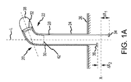
図1Aは、概してカテーテル20などの屈曲自在な医療装置を示し、これは、それに関連付けられた長手方向軸Lを有し、且つ先端部分22と基端部分24とをさらに有する。本発明は、いくつか例を挙げれば、限定なしにカテーテル及びアクセスシースを含む広範囲の屈曲自在な医療装置に有用であり得ることは理解されなければならない。さらに、背景技術で説明したとおり、プルワイヤ又は操縦ワイヤの作動は典型的には、例えば医師が手動で回転させることのできるノブなどの使用によるか、或いは1つ又は複数の機械的自由度を有するコンピュータ制御ロボット(例えば、関節式装置)の制御システムにより達成され得る。ロボット装置を使用した手順及び/又は手術の実施は増加しつつあり、本明細書に提供される装置(例えば、カテーテル又はシース)は様々なロボット応用に関連して利用されるように構成することができる。しかしながら、限定なしに、又は普遍性を失うことなく、図1A〜図1Bはロボット制御システムとの関連において説明されるが、本発明の実施形態が、手動で作動させる手順、並びに現在公知の、又は今後開発される他の方法と共に用いられ得ることは明確に理解されなければならない。
FIG. 1A shows a generally bendable medical device, such as a
引き続き図1Aを参照すると、カテーテル20の基端部分24は支持基材26に接続され、又は取り付けられ得る。コンピュータ制御式のロボットにより作動するカテーテル制御システムでは、支持基材26は使い捨てカートリッジの一部分であってよく、及びロボットカテーテルのマニピュレーションアセンブリと連動するように構成されてもよい。
With continued reference to FIG. 1A, the
先端部分22の屈曲を可能にするため、カテーテル20は複数の「プル」ワイヤ又は操縦ワイヤを含んでもよく、図1Aには、単一の平面内で屈曲させるのに適し得る第1の操縦ワイヤ28及び第2の操縦ワイヤ30が示される。操縦ワイヤ28、30は、各々、カテーテル本体の実質的な長さの範囲内でそれに沿って長手方向に位置する。操縦ワイヤ28、30は、高い弾性率を有する材料−例えばスチール又はアルミニウムなど−で形成されてもよい。プルワイヤ28、30はまた繊維性材料(例えば、KEVLAR(登録商標))を含んでもよく、プッシュ部材となり得る。カテーテル20はさらにプルリング又は操縦リング32を含んでもよく、これは先端部分22の一部分の内部に強固に接続又は固着された剛性リングの形態をとり得る。カテーテル20はさらなるプルリング又は操縦リング(すなわちアンカー−図示せず)を含んでもよい。各操縦ワイヤはプルリング32に接続されてもよい。或いは、複数のプルリング又はアンカーを有する実施形態では、複数のプル「ワイヤ」をあるアンカー上の異なる位置に連結することも、又は複数の異なるアンカーに連結することもできる。このように屈曲機構は、当該技術分野において公知の作製技術を含み得る。
To allow bending of the tip portion 22, the
概略的に図示されるとおり、操縦ワイヤ28、30の基端部分はそれぞれ制御部材34、36に接続され得る。カテーテル20は、図1Aに示されるとおりの先端電極38などの、様々な診断又は治療目的、例えば当該技術分野において公知のとおり、心臓組織の物理的若しくは電気的特徴の検出及びマッピング、又はアブレーションなどに用いられ得る1つ又は複数の電極をさらに含み得る。
As schematically illustrated, the proximal portions of the
カテーテル20が屈曲されていない状態に構成されるとき(図示せず)、制御部材34、36は双方とも、1つ又は複数の初期又は共通基準レベル又はデータム(例えば、図1Aに示される共通データムX)に位置し得る。操縦ワイヤの1つ又は複数を選択的に作動させ、又はそれに張力をかけることにより、先端部分22を長手方向軸Lから離れるように屈曲させ、又は動かすことができる。例えば、制御部材34を基端方向に距離ΔX1だけ並進させてもよく、それにより操縦ワイヤ28に張力応答が生じる。操縦ワイヤ28のこの作動により、図示されるとおり、対応して先端部分22が操縦ワイヤ28の側に回転し、屈曲する。制御部材34が距離ΔX1を第1の基端方向に能動的に屈曲される間、制御部材36はその反動として距離ΔX2を第2の実質的に逆向きの先端方向に動かされ、又は引き込まれる。
When the
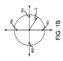
図1Bは、4本の操縦ワイヤ40a、40b、40c、40dを含むカテーテル実施形態の軸方向断面図である。本発明の実施形態は、2つの平面内で屈曲する屈曲自在な医療装置においても同様に使用することができ、4本の操縦ワイヤはかかる2つの平面での屈曲を促進するように構成される。加えて4本の操縦ワイヤ構成では、任意の半径方向への屈曲(以下に記載されるとおり)が、そのように構成される場合には可能となり得る。この図は全てが約90度離間されている操縦ワイヤを示すが、様々な他の構成が提供され得る。隣接する操縦ワイヤのそれぞれに張力をかけることにより、先端部分22の特有の方向、例えば方向Dへの屈曲が生じ得る。操縦ワイヤの対を選択的に作動させることにより、上側から長手方向軸Lを真っ直ぐ見下ろすように見たとき、先端部分22を様々な半径の円に旋回させる(すなわち、先端の屈曲が軸Lから離れる大きさに依存して)ことができる。4本ワイヤの実施形態は、任意の1本又は複数のワイヤに張力がかけられると(それが「引っ張られる」と)、それの反動として残りのワイヤが動くため、2本操縦ワイヤの実施形態と同様である。ここでも、複数のプルリング又はアンカーを有する代替的実施形態では、複数のプル「ワイヤ」をあるアンカー上の異なる位置に連結することも、又は複数の異なるアンカーに連結することもできる。コンピュータ制御式のロボットにより作動するカテーテル制御システムでは、制御器が、制御要素を並進させてカテーテル先端の所望の屈曲を実現するように構成され得る。
FIG. 1B is an axial cross-sectional view of a catheter embodiment including four
屈曲自在な医療装置が最大180〜270度の屈曲を繰り返し受けることは、珍しいことではない。このような繰り返される屈曲は、医療装置が患者の体内にしばらくの間配置されていた後、従って体温又はその近くの温度で起こり得る。さらに、心房細動の治療処置などの特定の手順では、医療装置が平均して数時間にわたり体内に留まり得る。結果として、従来の屈曲自在な医療装置が呈する軸方向の縮みの大きさは、繰り返し屈曲を受ける部分で徐々に増し、それにより利用可能な長さ/動程が減少する。この縮みにより、医師又はプログラムされたロボットによるカテーテル制御システムのいずれかによる補償の必要性が生じる。 It is not uncommon for a bendable medical device to repeatedly bend up to 180-270 degrees. Such repeated bending can occur after the medical device has been placed in the patient's body for some time, and thus at or near body temperature. In addition, in certain procedures, such as therapeutic treatment of atrial fibrillation, the medical device can remain in the body on average for several hours. As a result, the amount of axial shrinkage exhibited by conventional bendable medical devices gradually increases at the portions that are repeatedly subjected to bending, thereby reducing the available length / travel. This shrinkage creates a need for compensation by either a physician or a programmed robotic catheter control system.
軸方向の縮みを低減又は解消するため、本発明においては、医療装置が屈曲を受け得る当該部分の中に、及び/又はそこに通して、軸方向の縮み低減手段42(図1A)が配置される。手段42は本来繰り返し行われる屈曲に起因して起こり得る当該部分の軸方向の長さの縮みを低減又は解消するように構成される。手段42は、図4〜図14に関連して説明及び図示するとおり、複数の異なるストラット形態をとることができる。手段42はコラム支持、ひいては屈曲が繰り返される間の軸方向の長さの復元を提供すると同時に、医療装置を意図したとおり動作(すなわち、屈曲)させることを可能にするための一定の可撓性も提供する。 In order to reduce or eliminate axial shrinkage, in the present invention, axial shrinkage reducing means 42 (FIG. 1A) is disposed in and / or through the portion where the medical device can be bent. Is done. The means 42 is configured to reduce or eliminate axial length shrinkage of the portion that may occur due to repeated bending. The means 42 can take a number of different strut configurations, as described and illustrated in connection with FIGS. The means 42 provides column support, and thus axial length recovery during repeated flexing, while at the same time providing a certain flexibility to allow the medical device to operate (ie bend) as intended. Also provide.
詳細な説明を続ける前に、本明細書に説明及び図示する実施形態は、任意の半径方向に、又はさらには2つの平面内のみで(例えば、図1Bの4本ワイヤのカテーテルの実施形態を参照)屈曲するように構成された医療装置に適合し、従ってそうした医療装置において有用性が見出され得ることが理解されなければならない。しかしながら、本発明の実施形態はまた、他の構成の屈曲自在な医療装置においても同様に有用である。例えば、図示される実施形態は、1つの平面内のみで屈曲するように構成された医療装置に応用が見出され得る。 Prior to continuing the detailed description, the embodiments described and illustrated herein may be used in any radial direction, or even in only two planes (eg, the four-wire catheter embodiment of FIG. 1B). (See) It should be understood that it is compatible with medical devices configured to bend and thus may find utility in such medical devices. However, embodiments of the present invention are also useful in other configurations of flexible medical devices. For example, the illustrated embodiments may find application in medical devices that are configured to bend in only one plane.
図2は、医療装置50の屈曲自在な(屈曲自在な)先端部分の拡大断面図であり、本発明の一実施形態の態様をより明確に図示するよう誇張されている。普遍性を失うことなく、この医療装置は屈曲自在なアクセスシース50を含んでもよく、これは長手方向軸52と関係付けて示される。アクセスシース50は、動作時のシース50の案内又は操縦を可能にするように構成された従来のハンドルアセンブリ(図示せず)か、或いはコンピュータ制御式ロボットカテーテル制御システム(図示せず)に動作可能に接続され得る。シース50は、カテーテル、流体送達装置又は当該技術分野において公知のとおりの他の構造若しくは装置を受け入れるように構成された、比較的大きい直径の中心ルーメン54を含む。
FIG. 2 is an enlarged cross-sectional view of a bendable (flexible) tip portion of the
シース50は、内側管状ライナー56と、シースの屈曲自在な部分の軸方向縮みを低減するように構成されたストラット58と、1つ又は複数の操縦ワイヤ又はプルワイヤ62、64に接続された操縦リング又はプルリング60と、編組層66と、外側ポリマー層68とを有することが示される。場合により、シース50はまた、とりわけキンクを低減するように構成された、シース50の基端部分に向かって延在するコイル70(部分的に図示されている)も含み得る。ここでも普遍性を失うことなく変形例が企図され、例えば医療装置がアクセスシースである場合、上記に記載したとおり、中心コア構成要素は比較的大きい中心ルーメンを有する内側ライナーであってもよい。しかしながら、医療装置がカテーテルである場合、中心コア構成要素はカテーテルシャフトであってもよい。
The
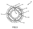
図3は、図2の実質的に線3−3に沿ったシース50の断面図であり、これもまた、そのいくつかの構成要素をより明確に図示するために誇張している。図3は2本のさらなるプルワイヤ72、74を示し、4本のプルワイヤ62、64、72、74の各々は、それぞれの管76により形成されるルーメン内にある。ワイヤ62、64、72、74は平面性部材(planarity member)として単独で(又は他の構造と共に)動作することができる。
FIG. 3 is a cross-sectional view of the
ここで図2及び図3の双方を参照すると、内側ライナー56はポリマー材料などの従来の材料、及びあくまでも例としてポリテトラフルオロエチレン(PTFE)材料を含み得る。内側ライナー56は、中心ルーメン54を画定する所望のサイズの内径を有するように構成される。プルリング60及び連係する操縦ワイヤ62、64、72、74も同様に、プルリングに対してはステンレス鋼材料及びプルワイヤに対しては平坦な(又は丸い)幾何形状のステンレス鋼ワイヤなど、従来の材料及び作製手法を含み得る。プルワイヤ62、64、72、74はまた繊維性材料(例えば、KEVLAR(登録商標))を含んでもよく、プッシュ部材となり得る。さらに、編組層66がプルワイヤを押さえ込む(すなわち、半径方向外側に屈曲しようとするのを制限する)ように構成されてもよく、あくまでも例として金属編組など(例えば、公知の編組パターンに従い編み上げられた0.002インチ厚×0.006インチ幅のワイヤ)、従来の材料及び作製手法を含み得る。外側層68は、あくまでも例として商標PEBAX(登録商標)のもとにArkema,Inc.から市販されている好適なデュロメータ及び融解温度のエラストマーなど、従来の溶融加工ポリマーを含み得る。ストラット58は、屈曲を受けると考えられるセクションに対応する軸方向長さを有するように構成されてもよい。作製した実施形態で採用した軸方向長さは約1.75インチ〜2.25インチの範囲であるが、この長さは任意の具体的な屈曲自在な医療装置の特定の構造詳細及び寸法に応じて異なり得ることは明確に理解さなければならない。
Referring now to both FIGS. 2 and 3, the
図4〜図15は、任意の半径方向に屈曲させることが可能な(全方向性の)アクセスシース50で使用されるストラット58の様々な実施形態を示す。しかしながら、特にストラット58がカテーテル若しくはシース以外の屈曲自在な装置に組み込まれるよう意図されるか、比較的単純若しくは複雑な形状を有する予め湾曲が付けられたタイプの装置に組み込まれるよう意図されるか、又は全方向性の屈曲ではなく、単一の平面若しくは2つの平面の屈曲可動域(上記のとおり)を有する屈曲自在な装置が意図されるとき、変形例が可能であることは理解されなければならない。
4-15 illustrate various embodiments of
図4は、ストラット58aと指示される、屈曲自在な医療装置に組み込まれるストラットの第1の実施形態の等角図である。ストラット58aは、第1の細長ロッド82と第2の細長ロッド84とにより一体に連結された、離間された第1の環状端部部材78と第2の環状端部部材80とを含む。ストラット58aは長手方向軸86と関係付けて示される。一実施形態において、軸86はアクセスシース50の軸52と一致する(すなわち、ストラット58aは例えば内側ライナー56等と同軸状に配置される)。代替的な実施形態では、軸86がシース50の軸52からオフセットしていてもよい。さらに別の代替的な実施形態では、ストラット58aが非一様な壁厚を有してもよい。
FIG. 4 is an isometric view of a first embodiment of a strut incorporated into a bendable medical device, indicated as strut 58a. The strut 58 a includes a first annular end member 78 and a second annular end member 80 that are spaced apart and connected together by a first
第1の環状端部部材78及び第2の環状端部部材80は、各々が、内側ライナー56の周りに嵌まるように構成された内径をそれぞれ有する中心貫通穴を有する(図3に最も分かりやすく図示される)。ストラット58aは、その構造の単純さに特に利点がある。ストラット58aは、比較的耐吸水性で、且つ比較的高い弾性率を有する従来の生体適合性材料であって、プルワイヤの1つ又は複数に加えられる典型的な力(例えば、5〜10ポンド、6〜7ポンドが典型的である)に応答して、典型的にはカテーテルの実施形態について約90〜270度及びアクセスシースの実施形態で約90〜180度であり得る考えられる屈曲範囲を考慮して、比較的高い機械的弾性歪みに好適であるように構成されるとおりの材料を含んでもよい。かかる材料は、好ましくはステンレス鋼又はニッケルチタン合金(例えば、超弾性NITINOL)などの金属材料を含み得るが、或いはポリテトラフルオロエチレン(PTFE−市販のTEFLON(登録商標))、ポリイミド、ポリエーテルエーテルケトン(すなわち、PEEK)、ポリアミド(すなわち、ナイロン)又は他の熱可塑性材料などの材料を含んでもよい。あくまでも例として、ステンレス鋼は27Mpsiより高い弾性率を有してもよく、Nitinolは約4〜10Mpsi又はそれ以上の弾性率を有してもよく、一方ポリイミド及びポリエーテルエーテルケトンは約0.5Mpsi前後の弾性率を有してもよい。 The first annular end member 78 and the second annular end member 80 each have a central through hole each having an inner diameter configured to fit around the inner liner 56 (best seen in FIG. 3). Easy to illustrate). The strut 58a is particularly advantageous for its simplicity of construction. The strut 58a is a conventional biocompatible material that is relatively water resistant and has a relatively high modulus of elasticity, which is typically a force applied to one or more of the pull wires (eg, 5-10 pounds, 6 to 7 pounds is typical), considering possible bending ranges that can typically be about 90-270 degrees for catheter embodiments and about 90-180 degrees for access sheath embodiments And may include materials as configured to be suitable for relatively high mechanical elastic strains. Such materials may preferably comprise metallic materials such as stainless steel or nickel titanium alloys (eg superelastic NITINOL), or alternatively polytetrafluoroethylene (PTFE—commercially available TEFLON®), polyimide, polyetherether It may include materials such as ketones (ie, PEEK), polyamides (ie, nylon) or other thermoplastic materials. By way of example only, stainless steel may have a modulus greater than 27 Mpsi, Nitinol may have a modulus of about 4-10 Mpsi or higher, while polyimide and polyetheretherketone are about 0.5 Mpsi. You may have front and back elastic modulus.
図5〜図6は、ストラット58bと指示される、屈曲自在な医療装置で使用されるストラットの第2の実施形態の等角図である。図5に示されるとおり、ストラット58bは長手方向軸88と関係付けて示される。一実施形態において、軸88はシース50の軸52と一致する(すなわち、ストラット58bは例えば内側ライナー56等と同軸状に配置される)。ストラット58bは、接続格子94により一体に連結された、離間された第1の環状端部部材90と第2の環状端部部材92とを含む。第1の環状端部部材90及び第2の環状端部部材92は、各々が、内側ライナー56の周りに嵌まるよう構成される内径(例えば、図6の内径100)をそれぞれ有する中心貫通穴(図3に図示)を有する。
5-6 are isometric views of a second embodiment of a strut used in a bendable medical device, designated as
図6にさらに詳細に示されるとおり、接続格子94は複数本の離間されたらせん状接続要素を含み、ストラット58bにはらせん状接続要素961、962、963及び964と指示される4つのかかるらせん状要素が組み込まれる。複数のらせん状接続要素961、962、963及び964は複数の撓み結節点981、982、...、98nで公差する。らせん状接続要素961、962、963及び964は、長手方向に整列した撓み結節点を参照して見たとき、格子94が第1の所定の距離102の第1の軸方向ピッチ間隔を呈するように配列される。図示されるとおり、格子94はさらに、隣接するものの円周方向にはオフセットしている撓み結節点に関して見たとき、第2の所定の距離104の第2の軸方向ピッチ間隔を呈する。加えて、例示される実施形態において、各らせん状接続要素961、962、963及び964は、所定の幅106として示される呼び幅を有する。
As shown in more detail in FIG. 6, the
ストラット58bは、比較的耐吸水性で、且つ比較的高い弾性率を有する従来の生体適合性材料であって、プルワイヤの1つ又は複数に加えられる典型的な力(例えば、5〜10ポンド、6〜7ポンドが典型的である)に応答して、典型的にはカテーテルの実施形態について約90〜270度及びアクセスシースの実施形態で約90〜180度であり得る考えられる屈曲範囲を考慮して、比較的大きい機械的弾性歪みに好適であるように構成されるとおりの材料を含んでもよい。かかる材料は、好ましくはステンレス鋼又はニッケルチタン合金(例えば、超弾性NITINOL)などの金属材料を含み得るが、或いはポリテトラフルオロエチレン(PTFE−市販のTEFLON)、ポリイミド、ポリエーテルエーテルケトン(すなわち、PEEK)、ポリアミド(すなわち、ナイロン)又は他の熱可塑性材料などの材料を含んでもよい。あくまでも例として、ステンレス鋼は27Mpsiより高い弾性率を有してもよく、Nitinolは約4〜10Mpsi又はそれ以上の弾性率を有してもよく、一方ポリイミド及びポリエーテルエーテルケトンは約0.5Mpsi前後の弾性率を有してもよい。
The
一実施形態において、ストラット58bは、近似内径(ID)が約0.025インチで、壁厚が約0.004インチのニッケルチタン(NiTi)レーザーカット管を使用して形成した。上記は例示に過ぎず、他の公知の製造手法が用いられてもよく、他の材料が使用されてもよく、また他の構成要素寸法が実現されてもよいため、本質的に限定するものではないことが理解されなければならない。 In one embodiment, struts 58b were formed using a nickel titanium (NiTi) laser cut tube having an approximate inner diameter (ID) of about 0.025 inches and a wall thickness of about 0.004 inches. The above is merely an example, and other known manufacturing techniques may be used, other materials may be used, and other component dimensions may be realized, which are essentially limiting It must be understood that this is not the case.
ストラット58bは対称的な設計であるため、いずれの半径方向に見たときも実質的に一様な屈曲抵抗性並びに軸方向長さの復元性を提供する。このことは、屈曲があらゆる半径方向に企図される屈曲自在な医療装置の実施形態において特定の利点を提供するが、しかしながら上記のとおり、単一の又は2つの平面で屈曲する実施形態であっても、ストラット58bはとりわけ平面性の向上を提供し得る。全体的な屈曲抵抗性レベル(すなわち、屈曲に必要な力の大きさ)は、材料、らせん状要素の数及び各々の幅、並びに撓み結節点間の軸方向ピッチに応じて定義される。
Since the
図7は、ストラット58cと指示される、屈曲自在な医療装置において使用されるストラットの第3の実施形態の等角図である。ストラット58cは長手方向軸108と関係付けて示される。ストラット58cは、接続格子114により一体に連結された、離間された第1の環状端部部材110と第2の環状端部部材112とを含む。上記で行ったストラット58bの説明は、以下を除いてはストラット58cのあらゆる点に当てはまる。格子114は、より多数の離間されたらせん状接続要素、例えば示されるとおり8個のかかるらせん状接続要素、並びにより短い撓み結節点間のピッチ間隔を含む。らせん状接続要素の数が増えることで軸方向縮みに対するより大きい耐量が提供される(すなわち、コラム強度がより高いことで軸方向縮みが減少する)。しかしながら、ストラット58cは剛性がより高いため、実に屈曲抵抗性が大きくなり、従って所望の屈曲量(例えば180〜270度)を実現するのに必要な力の大きさも増す。
FIG. 7 is an isometric view of a third embodiment of a strut used in a bendable medical device, designated
図8は、ストラット58dと指示される、屈曲自在な医療装置において使用されるストラットの第4の実施形態の等角図である。ストラット58dは長手方向軸116と関係付けて示される。ストラット58dは、接続格子122により一体に連結された、離間された第1の環状端部部材118と第2の環状端部部材120とを含む。上記で行ったストラット58bの説明は、以下を除いてはストラット58cのあらゆる点に当てはまる。格子122のらせん状接続要素は、ストラット58bにおけるらせん状接続要素の所定の幅106と比べて太い。らせん状接続要素の数、及び対応するピッチ間隔はストラット58bと同様であるが、幅が増すことで軸方向縮みに対するより大きい耐量が提供される(すなわち、コラム強度がより高いことで軸方向縮みが減少する)。しかしながら、ストラット58dは剛性がより高いため、実に屈曲抵抗性が大きくなり、従って所望の屈曲量(例えば180〜270度)を実現するのに必要な力の大きさも増す。
FIG. 8 is an isometric view of a fourth embodiment of a strut used in a bendable medical device, indicated as strut 58d. The strut 58d is shown in relation to the
図9は、ストラット58eと指示される、屈曲自在な医療装置において使用されるストラットの第5の実施形態の等角図である。ストラット58eは長手方向軸124と関係付けて示される。ストラット58eは、接続格子130により一体に連結された、離間された第1の環状端部部材126と第2の環状端部部材128とを含む。上記で行ったストラット58bの説明は、以下を除いてはストラット58eのあらゆる点に当てはまる。格子122のらせん状接続要素はストラット58bのらせん状接続要素の所定の幅106と比べて細い。らせん状接続要素の数、及び対応するピッチ間隔はストラット58bのものと同様であるが、らせん状要素の幅が減ることで、所望の屈曲量(例えば180〜270度)を実現するのに必要な力の大きさの低下がもたらされる。しかしながら、らせん状要素が細くなると、少なくともストラット58b、58c及び58dと比較して、軸方向縮みの防止効果もまた低下する。
FIG. 9 is an isometric view of a fifth embodiment of a strut used in a bendable medical device, designated
図10は、ストラット58fと指示される、ストラットの第6の実施形態の等角図である。ストラット58fは長手方向軸132と関係付けて示される。ストラット58fは、対向する第1の端部136と第2の端部138との間に例えばらせん形状で配置された連続ワイヤ要素により画定されるコイル134を含む。一実施形態において、軸132はアクセスシース50の軸52と一致する(すなわち、ストラット58fは例えば内側ライナー56等と同軸状に配置される)。
FIG. 10 is an isometric view of a sixth embodiment of a strut, designated strut 58f. The strut 58f is shown in relation to the
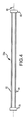
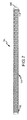
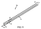
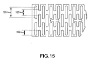
図11〜図14は、ストラット58gと指示される、ストラットの第7の好ましい実施形態の図である。図11は、長手方向軸140と関係付けて示されるストラット58gの等角図である。一実施形態において、軸140はシース50の軸52と一致する(すなわち、ストラット58gは例えば内側ライナー56等と同軸状に配置される)。ストラット58gは、複数の開口部、例えば壁厚を貫通して形成されたスロット144を有する薄肉管142を含む。好ましくは、スロット144は(軸方向の配置に対比されるものとして)円周方向に置かれる。すなわち、スロット144は管上での長手方向の長さと比べて円周方向の長さのほうが長い。例示される実施形態において、スロット144は列の第1のペア146に配列される。この列のペア146は直径を隔てて両側にあり(すなわち、互いに180度オフセットしており)、且つ長手方向に延在する。例示される実施形態において、スロット144はさらに列の第2のペア148に配列される。列の第2のペア148もまた直径を隔てて両側にあり、且つ長手方向に延在する。図11では列のペア148の一方しか見えず、列のペアの他方は180度オフセットしていることに留意されたい。列の第1のペア146における各列中のスロット144は位置が揃っている。同様に、列の第2のペア148における各列中のスロット144もまた位置が揃っている。しかしながら、列146のスロット144は、列148のスロット144と軸方向にオフセットしている。
FIGS. 11-14 are views of a seventh preferred embodiment of a strut, designated as
図12は、図11のストラット58gの側面図である。ストラット58gは離間された第1の環状端部部材150と第2の環状端部部材152とを含み、所定の軸方向長さ154を有する。
FIG. 12 is a side view of the
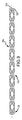
図13は、ストラット58gの丸で囲んだ先端部分をさらに詳細に示す部分側面図である。特に、図13は、列のペア148の一方に沿って形成されたスロット144の正面図である(明確にするため、図13では1つのスロット144のみを特定している)。スロットの列148に沿ったスロット144は、第1の所定の距離156の第1の軸方向ピッチ間隔を呈する。ピッチ間隔156は、列に沿って整列する隣接するスロットに関係している。さらに示すとおり、隣接する列のスロットは、第2の所定の距離158の第2の軸方向ピッチ間隔を呈する。ピッチ158は、ストラットの周囲上のいずれかに位置するスロット間の軸方向距離を示す。スロット144の各々は呼び幅160を有し得る。
FIG. 13 is a partial side view showing in more detail the tip of the
スロット58gはさらに、場合により、コアを通って延在する電極導体が、それぞれの電極との電気的接続のためにストラットを通過できるように構成された、軸方向に延在するスロット144aなどの1つ又は複数のさらなる開口部を含んでもよい。シース用途では中心ルーメンは空いた状態でなければならないため、スロット144aは、好ましくは電極を備えるカテーテルの実施形態にのみ存在する。図13は、軸方向距離162の間隔を置いた2個のかかるスロット144aを示しているが、スロット144aの数及びそれぞれの間隔は、好ましくはカテーテルにある電極の数及び間隔に対応する。スロット144aの各々は、呼び軸方向長さ164(各端部のラジアス形の延在部は含めない)と、そこを通過する導体が破損したり、又はその他の形でストラットに当たってショートしたりすることのないような高さとを有する。スロット144aの各々はまた、それらが一部をなす円周方向に延在するスロット144の中心線からオフセット距離166だけオフセットしていてもよい。
The
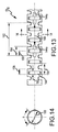
図14は、図13の実質的に線14−14に沿ったストラット58gの部分断面図である。図示されるとおり、第1の環状端部部材150及び第2の環状端部部材152は、各々、内側ライナー56の外径の周りに嵌まるように構成された内径(例えば、内径168)をそれぞれ有する中心貫通穴を有する。加えて、スロットは好ましくは軸140に対して中心角θにわたり円周方向に延在している。
14 is a partial cross-sectional view of
図15は、ストラット58gのいわゆる平面パターンの(すなわち、周囲を平面に投影して見たときの)拡大図である。図示されるとおり、スロット144が所定の長さ165(端部のラジアル部は含まず−図示されるとおり)を有し得る一方、同じ平面内のスロット144が所定の間隔167(端部のラジアル部は含まず−図示されるとおり)だけ隔てられ得る。ストラット58gは全方向に屈曲するよう構成されるため、隣接する列のスロット144は、所定の最小量の重なり169を有するように配列される。重なり169はいかなる半径方向にも十分な可撓性を提供するためのものである。例えば、一平面上又は二平面上での屈曲に関する代替的実施形態では、必ずしもスロットの重なりを有する必要はないこともある。
FIG. 15 is an enlarged view of a so-called plane pattern of the
ストラット58gは、比較的耐吸水性で、且つ比較的高い弾性率を有する従来の生体適合性材料であって、プルワイヤの1つ又は複数に加えられる典型的な力(例えば、5〜10ポンド、6〜7ポンドが典型的である)に応答して、典型的にはカテーテルの実施形態について約90〜270度及びアクセスシースの実施形態で90〜180度であり得る考えられる屈曲範囲を考慮して、比較的大きい機械的弾性歪みに好適であるように構成されるとおりの材料を含み得る。かかる材料は、好ましくはステンレス鋼又はニッケルチタン合金(例えば、超弾性NITINOL)などの金属材料を含み得るが、或いはポリテトラフルオロエチレン(PTFE−市販のTEFLON)、ポリイミド、ポリエーテルエーテルケトン(すなわちPEEK)、ポリアミド(すなわち、ナイロン)又は他の熱可塑性材料などの材料を含んでもよい。あくまでも例として、ステンレス鋼は27Mpsiより高い弾性率を有してもよく、Nitinolは約4〜10Mpsi又はそれ以上の弾性率を有してもよく、一方ポリイミド及びポリエーテルエーテルケトンは約0.5Mpsi前後の弾性率を有してもよい。
The
一実施形態において、ストラット58gは、酸化物仕上げで直に焼鈍された超弾性ニチノール(ニッケルチタン−NiTi)チュービングから形成されるレーザーカット管を含み得る。レーザー切断後、チュービングを直線構成にエッチング又は電解研磨してレーザースラグ及び粗いエッジを取り除き得る。0.004インチ呼び壁厚を有する0.059インチ外径の超弾性ニチノールチュービングから形成された実施形態は、以下の寸法構成となる:呼び長さ(すなわち、図12の参照符号154)が2.25インチ、内径(すなわち、図14の参照符号168)が0.053インチ±0.001インチ、外径が0.059インチ±0.001インチ、短いピッチ(すなわち、図13の参照符号158)が0.022インチ、長いピッチ(すなわち、図13の参照符号156)が0.044インチ、スロット延在範囲(すなわち、図14の参照符号θ)が115度、スロット幅が典型的に0.013インチ、スロット長さが典型的に0.059インチ(平面パターンによる−図15の長さ165を参照)、及びスロット分離距離が典型的に0.033インチ(平面パターンによる−図15の距離167を参照)。
In one embodiment, the
レーザーカット0.115インチ外径超弾性ニチノール(ニッケルチタン−NiTi)チュービングで形成される別の実施形態は、以下の寸法構成となる:呼び長さ(すなわち、図12の参照符号154)が2.10インチ、内径(すなわち、図14の参照符号168)が0.107インチ±0.001インチ、外径が0.115インチ±0.001インチ、短いピッチ(すなわち、図13の参照符号158)が0.033インチ±0.003インチ、及びスロット幅が典型的に約0.016インチ±0.002インチ。
Another embodiment formed with laser cut 0.115 inch outer diameter superelastic Nitinol (Nickel Titanium-NiTi) tubing has the following dimensional configuration: Nominal length (ie, reference numeral 154 in FIG. 12) is 2. .10 inch, inner diameter (ie, reference numeral 168 in FIG. 14) is 0.107 inch ± 0.001 inch, outer diameter is 0.115 inch ± 0.001 inch, short pitch (ie,
0.133インチ外径の超弾性ニチノール(ニッケルチタン−NiTi)チュービングから形成されるさらに別の実施形態は、以下の寸法構成となる:呼び長さ(すなわち、図12の参照符号154)が2.10インチ、内径(すなわち、図14の参照符号168)が0.125インチ±0.001インチ、外径が0.133インチ±0.001インチ、短いピッチ(すなわち、図13の参照符号158)が0.039インチ±0.003インチ、及びスロット幅が典型的に0.019インチ±0.002インチ。
Yet another embodiment formed from 0.133 inch outer diameter superelastic Nitinol (Nickel Titanium-NiTi) tubing has the following dimensional configuration: Nominal length (ie, reference numeral 154 in FIG. 12) is 2. .10 inch, inner diameter (ie, reference numeral 168 in FIG. 14) is 0.125 inch ± 0.001 inch, outer diameter is 0.133 inch ± 0.001 inch, short pitch (ie,
ここで、図2〜図3及び図16〜図20を参照して、ストラット58の実施形態を組み込む医療装置の製造方法について記載する。
A method of manufacturing a medical device incorporating an embodiment of the
図16は、先端部分172と基端部分174とを有するマンドレル170を示す。マンドレル170は半径方向断面が円形で、且つ作製される屈曲自在な医療装置に鑑みて望ましい長さを有し得る。
FIG. 16 shows a
図17に示されるとおり、次に上記に説明される内側ライナー56がマンドレル170上に置かれ得る。マンドレル170上に取り付けた後、内側ライナー56は、例えば一方又は双方の端部を結ぶことにより固定されてもよい。
As shown in FIG. 17, the
図18に示されるとおり、次にストラット58がマンドレル170の先端に、ライナー56を覆って取り付けられる(先端部分が医療装置の屈曲部である実施形態について)。加えて、場合により、コイル70がストラット58の基端部分から装置の基端に向かって延在する場合にコイル70をストラット58に取り付け、そこに突き合わせてもよい。次にプルリング60がライナー56上に/それを覆って置かれ、ストラット58の先端側に至るまで、且つそれに突き合わせて置かれる。プルワイヤ62、64、72、74(管76に封入される)がプルリング60から延在してストラット58(及び存在する場合にはコイル70)の上にわたって置かれ、基端方向に延在する。ストラット58はプルリングに直接隣接し、装置のうち屈曲を受けるセクションに対応する長さにわたって軸方向に延在することに留意されたい。
As shown in FIG. 18, the
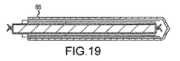
図19に示されるとおり、次のステップは、編組層66などのシース層を(例えば、プルワイヤの外側への屈曲を抑えるため)、プルワイヤを覆って置くことを含み得る。
As shown in FIG. 19, the next step may include placing a sheath layer, such as
図20に示されるとおり、次に外側層68(例えば、PEBAX材料)が、このように形成されたサブアセンブリを覆って置かれる。外側層68は、チュービングの単一のセクションか、或いは共に突き合わされた、又は互いに重ね合わされた複数のセクションのいずれを含んでもよい。シース材料の複数のセグメント、又は層は、当該技術分野において公知のとおりの、設計の柔軟性を許容する任意の長さ及び/又は硬さ(デュロメータ)であってよい。
As shown in FIG. 20, an outer layer 68 (eg, PEBAX material) is then placed over the thus formed subassembly. The
次に、このように形成されたアセンブリがリフローラミネート加工に供され、この加工は、外側層材料が流動して周囲にわたり分布し直すまでアセンブリを加熱することを含む。次に装置50が冷却される。次に装置50の先端部分及び基端部分が所望の方法で仕上げられ得る。
The assembly thus formed is then subjected to a reflow laminating process that includes heating the assembly until the outer layer material flows and redistributes around. The
概して、ストラット58の様々な実施形態に関連して上記に説明したものを除き、アクセスシース50(又はカテーテルの実施形態ではカテーテル)を製造するための材料及び作製方法は、あくまでも例として、本発明と同一の譲受人が所有し、且つ本明細書によって全体として参照により援用される2007年7月18日に出願された「CATHETER AND INTRODUCER CATHETER HAVING TORQUE TRANSFER LAYER AND METHOD OF MANUFACTURE」と題される米国特許出願第11/779,488号明細書を参照することにより分かるとおりの、対応する従来の材料及び作製方法を含み得る。
In general, except for those described above in connection with various embodiments of
上記は例示に過ぎず、他の公知の製造手法が用いられてもよく、他の材料が使用されてもよく、及び構成要素寸法が実現されてもよいため、本質的に限定するものではないことが理解されなければならない。 The above is merely exemplary and is not inherently limiting as other known manufacturing techniques may be used, other materials may be used, and component dimensions may be realized. It must be understood.
ストラット58gは、選択した半径方向に関して見たとき実質的に一様な屈曲抵抗性並びに軸方向長さの復元性を提供する。全方向に屈曲させる実施形態では、ストラット58gの対称的な設計により、例えば、任意の半径方向に見たとき実質的に一様な屈曲抵抗性並びに軸方向長さの復元性が提供される。上記は、任意の半径方向への屈曲が企図される屈曲自在な医療装置の実施形態に特に利点を提供するが、しかしながら上記に記載したとおり、一平面又は二平面の屈曲であっても、ストラット58bはとりわけ平面性の向上を提供し得る。全体的な屈曲抵抗性レベル(すなわち、所望量の屈曲を実現するのに必要な力の大きさ)は、材料、らせん状要素の数及び各々の幅、並びに撓み結節点間の軸方向ピッチに応じて定義される。
The
心房細動(AF)などの心調律障害のアブレーション処置を対象とした用途については、本発明の実施形態を組み込むカテーテルシステムは、ポジショニング/ナビゲーション装置及び/又は電気生理学的マッピング装置の一方又は双方、例えばSt.Jude Medical EnSite(商標) Navxシステム又は当該技術分野において公知の他のシステム、例えば、検出磁場に基づくポジショニングシステム(例えば、Mediguide Inc.のMedical Positioning System(gMPS)、Biosense Webster,Inc.のCARTOナビゲーション及びロケーションシステム、又はNorthern Digital Inc.のAURORA(登録商標)システム(これらは全て、電場ではなく磁場を利用する)と組み合わせてもよい。かかるポジショニング、ナビゲーション及び/又はマッピング装置の使用は、本発明の実施形態を組み込むカテーテルに電極及び/又は磁気センサを装着し、それによりかかる公知の装置が三次元空間における位置及び向きを決定し、EPマップ又は解剖学的構造マップ又は画像に対してかかるカテーテルを追跡及び誘導できるようにすることを含み得る。 For applications directed to ablation treatment of cardiac rhythm disorders such as atrial fibrillation (AF), a catheter system incorporating embodiments of the present invention can include one or both of a positioning / navigation device and / or an electrophysiological mapping device, For example, St. The Jude Medical EnSite ™ Navx system or other systems known in the art, such as a positioning system based on a detected magnetic field (eg, Medical Positioning System (gMPS) from Medical Inc., CARTO Navigation from Biosense Webster, Inc.). Location systems, or Northern Digital Inc.'s AURORA® system, all of which utilize a magnetic field rather than an electric field, use of such positioning, navigation and / or mapping devices is An electrode and / or magnetic sensor is attached to the catheter incorporating the embodiment, thereby providing three such known devices. Determining the position and orientation in the original space can include to track and induce such catheter relative EP map or anatomical structure map or image.
本発明の数々の実施形態を上記にある程度詳細に説明したが、当業者は、本発明の趣旨及び範囲から逸脱することなく、開示される実施形態の代替例を多数実現し得る。方向性に関するあらゆる言及(例えば、プラス、マイナス、上側、下側、上方、下方、左、右、左側、右側、上端、下端、超、未満、垂直、水平、時計回り、及び反時計回り)は、本発明の読者の理解を促進するよう識別のために使用されるに過ぎず、特に位置、向き、又は本発明の使用に関して限定をもたらすものではない。つなぎ合わせることに関する言及(例えば、取り付けされる、連結される、接続されるなど)は広義に解釈されるべきであり、要素の接続の間にある中間的な構成物及び要素間の相対的な移動を含み得る。従って、つなぎ合わせることに関する言及は、必ずしも2つの要素が直接的に、互いに固定的な関係で接続されることを含意するものではない。上記の説明に含まれ、且つ添付の図面に示される事項は全て、限定ではなく、あくまでも例示として解釈されなければならないことが意図される。添付の特許請求の範囲に定義されるとおりの本発明の趣旨から逸脱することなく、詳細又は構造の変更を実現することができる。 While numerous embodiments of the present invention have been described in some detail above, those skilled in the art can implement many alternative embodiments of the disclosed embodiments without departing from the spirit and scope of the present invention. Any reference to directionality (eg, plus, minus, top, bottom, top, bottom, left, right, left, right, top, bottom, super, less, vertical, horizontal, clockwise, and counterclockwise) It is only used for identification to facilitate the reader's understanding of the present invention, and does not provide any limitation as to location, orientation, or use of the present invention. References to splicing (eg, attached, coupled, connected, etc.) should be interpreted broadly, with intermediate components between element connections and relative between elements Can include movement. Thus, references to stitching do not necessarily imply that the two elements are directly connected in a fixed relationship to each other. It is intended that all matter contained in the above description and shown in the accompanying drawings shall be interpreted as illustrative rather than limiting. Changes in detail or structure may be realized without departing from the spirit of the invention as defined in the appended claims.
Claims (21)
その屈曲自在な先端が当初の軸方向長さより圧縮されてしまう状態をもたらす繰り返し屈曲に起因して前記細長コアの前記屈曲自在な先端部分が軸方向に縮むことを低減するように構成されており、前記コアの外側であって前記先端部分に配置されており、長手方向に貫通している中心開孔を備えているストラットと、
前記ストラットの先端側に連結されている操縦リングと、
前記操縦リングに連結されているとともに、前記コアの前記基端部分まで延在しており、前記ストラットの半径方向外側であって前記中心開孔の完全に外側に配置されている複数本の操縦ワイヤと、
前記コアの外側において前記ストラットの基端側に連結されているコイルと、
複数本の編み込まれたワイヤで構成されているとともに、前記操縦ワイヤを取り囲んでいるワイヤメッシュと、
を含む医療装置。 An elongated core having a proximal end portion and a bendable distal end portion;
The bendable tip portion of the elongate core is configured to reduce contraction in the axial direction due to repeated bending resulting in a state where the bendable tip is compressed from its original axial length. A strut having a central aperture disposed outside the core and at the tip portion and penetrating in a longitudinal direction;
A steering ring connected to the distal end side of the strut;
A plurality of maneuvers coupled to the maneuvering ring and extending to the proximal end portion of the core and disposed radially outside the strut and completely outside the central aperture Wire,
A coil connected to the base end side of the strut outside the core ;
A wire mesh composed of a plurality of braided wires and surrounding the steering wire;
Including medical devices.
その屈曲自在な先端が当初の軸方向長さより圧縮されてしまう状態をもたらす繰り返し屈曲に起因して前記細長コアの前記屈曲自在な先端部分が軸方向に縮むことを低減するように構成されており、前記コアの外側であって前記先端部分に配置されており、長手方向に貫通している中心開孔を備えているストラットと、
前記ストラットの先端側に連結されている操縦リングと、
前記操縦リングに連結されているとともに、前記コアの前記基端部分まで延在しており、前記ストラットの半径方向外側であって前記中心開孔の完全に外側に配置されている複数本の操縦ワイヤと、
複数本の編み込まれたワイヤで構成されているとともに、前記操縦ワイヤを取り囲んでいるワイヤメッシュと、
を含む医療装置。 An elongated core having a proximal end portion and a bendable distal end portion;
The bendable tip portion of the elongate core is configured to reduce contraction in the axial direction due to repeated bending resulting in a state where the bendable tip is compressed from its original axial length. A strut having a central aperture disposed outside the core and at the tip portion and penetrating in a longitudinal direction;
A steering ring connected to the distal end side of the strut;
A plurality of maneuvers coupled to the maneuvering ring and extending to the proximal end portion of the core and disposed radially outside the strut and completely outside the central aperture Wire,
A wire mesh composed of a plurality of braided wires and surrounding the steering wire;
Including medical devices.
Applications Claiming Priority (3)
| Application Number | Priority Date | Filing Date | Title |
|---|---|---|---|
| US12/615,016 US8376991B2 (en) | 2009-11-09 | 2009-11-09 | Device for reducing axial shortening of catheter or sheath due to repeated deflection |
| US12/615,016 | 2009-11-09 | ||
| PCT/US2010/049741 WO2011056311A1 (en) | 2009-11-09 | 2010-09-22 | Device for reducing axial shortening of catheter or sheath due to repeated deflection |
Publications (3)
| Publication Number | Publication Date |
|---|---|
| JP2013509946A JP2013509946A (en) | 2013-03-21 |
| JP2013509946A5 JP2013509946A5 (en) | 2013-08-15 |
| JP5632007B2 true JP5632007B2 (en) | 2014-11-26 |
Family
ID=43970228
Family Applications (1)
| Application Number | Title | Priority Date | Filing Date |
|---|---|---|---|
| JP2012537882A Active JP5632007B2 (en) | 2009-11-09 | 2010-09-22 | Device for reducing axial contraction of catheter or sheath due to repeated bending |
Country Status (5)
| Country | Link |
|---|---|
| US (3) | US8376991B2 (en) |
| EP (1) | EP2448626B1 (en) |
| JP (1) | JP5632007B2 (en) |
| CN (1) | CN102548603B (en) |
| WO (1) | WO2011056311A1 (en) |
Families Citing this family (66)
| Publication number | Priority date | Publication date | Assignee | Title |
|---|---|---|---|---|
| US7959601B2 (en) * | 2005-02-14 | 2011-06-14 | Biosense Webster, Inc. | Steerable catheter with in-plane deflection |
| US9114229B2 (en) * | 2006-12-29 | 2015-08-25 | St. Jude Medical, Af Division, Inc. | Dual braid reinforcement deflectable device |
| US9950141B2 (en) | 2006-12-29 | 2018-04-24 | St. Jude Medical, Atrial Fibrillation Division, Inc. | Dual braid reinforcement deflectable device (sheath or catheter) |
| US12220538B2 (en) | 2008-12-08 | 2025-02-11 | Scientia Vascular, Inc. | Micro-fabricated intravascular devices having varying diameters |
| US9101733B2 (en) * | 2009-09-29 | 2015-08-11 | Biosense Webster, Inc. | Catheter with biased planar deflection |
| US8376991B2 (en) * | 2009-11-09 | 2013-02-19 | St. Jude Medical, Atrial Fibrillation Division, Inc. | Device for reducing axial shortening of catheter or sheath due to repeated deflection |
| TWI556849B (en) | 2010-10-21 | 2016-11-11 | 美敦力阿福盧森堡公司 | Catheter apparatus for renal neuromodulation |
| WO2012061159A1 (en) | 2010-10-25 | 2012-05-10 | Medtronic Ardian Luxembourg S.A.R.L. | Catheter apparatuses having multi-electrode arrays for renal neuromodulation and associated systems and methods |
| WO2012061657A2 (en) * | 2010-11-03 | 2012-05-10 | Biocardia, Inc. | Steerable endoluminal devices and methods |
| US8560086B2 (en) | 2010-12-02 | 2013-10-15 | St. Jude Medical, Atrial Fibrillation Division, Inc. | Catheter electrode assemblies and methods of construction therefor |
| US12150851B2 (en) * | 2010-12-30 | 2024-11-26 | Claret Medical, Inc. | Method of isolating the cerebral circulation during a cardiac procedure |
| US9089631B2 (en) | 2011-07-22 | 2015-07-28 | Cook Medical Technologies Llc | Irrigation devices adapted to be used with a light source for the identification and treatment of bodily passages |
| US9370447B2 (en) * | 2011-10-10 | 2016-06-21 | Cygnus LP | Probes for use in ophthalmic and vitreoretinal surgery |
| US9375138B2 (en) | 2011-11-25 | 2016-06-28 | Cook Medical Technologies Llc | Steerable guide member and catheter |
| US20130190561A1 (en) * | 2012-01-10 | 2013-07-25 | Boston Scientific Scimed, Inc. | Steerable medical device having an imaging system |
| US8789317B2 (en) * | 2012-01-17 | 2014-07-29 | James L. CHEH | Method for forming a double-curved structure and double-curved structure formed using the same |
| ES2614272T3 (en) | 2012-05-11 | 2017-05-30 | Medtronic Ardian Luxembourg S.à.r.l. | Multiple electrode catheter assemblies for renal neuromodulation and associated systems and methods |
| US9314593B2 (en) | 2012-09-24 | 2016-04-19 | Cook Medical Technologies Llc | Medical devices for the identification and treatment of bodily passages |
| US9044575B2 (en) | 2012-10-22 | 2015-06-02 | Medtronic Adrian Luxembourg S.a.r.l. | Catheters with enhanced flexibility and associated devices, systems, and methods |
| JP6073486B2 (en) * | 2012-11-09 | 2017-02-01 | カーディアック ペースメイカーズ, インコーポレイテッド | Implantable lead and method for manufacturing the same |
| WO2014098011A1 (en) * | 2012-12-18 | 2014-06-26 | 住友ベークライト株式会社 | Medical device |
| EP2961308B1 (en) | 2013-02-28 | 2020-03-18 | Cook Medical Technologies LLC | Medical devices, systems, and methods for the visualization and treatment of bodily passages |
| EP2968856B1 (en) * | 2013-03-16 | 2019-05-01 | Clph, Llc | Steerable catheters and methods for making them |
| JP6201368B2 (en) * | 2013-03-27 | 2017-09-27 | 住友ベークライト株式会社 | Medical equipment |
| JP6209841B2 (en) * | 2013-03-27 | 2017-10-11 | 住友ベークライト株式会社 | Medical equipment |
| JP6152676B2 (en) * | 2013-03-27 | 2017-06-28 | 住友ベークライト株式会社 | Medical device and method for manufacturing medical device |
| EP2996754B1 (en) | 2013-05-18 | 2023-04-26 | Medtronic Ardian Luxembourg S.à.r.l. | Neuromodulation catheters with shafts for enhanced flexibility and control and associated devices and systems |
| AU2014284381B2 (en) | 2013-07-01 | 2019-04-18 | Zurich Medical Corporation | Apparatus and method for intravascular measurements |
| US10835183B2 (en) | 2013-07-01 | 2020-11-17 | Zurich Medical Corporation | Apparatus and method for intravascular measurements |
| US9549748B2 (en) | 2013-08-01 | 2017-01-24 | Cook Medical Technologies Llc | Methods of locating and treating tissue in a wall defining a bodily passage |
| US11116941B2 (en) | 2013-12-10 | 2021-09-14 | St. Jude Medical, Atrial Fibrillation Division, Inc. | Catheter curve shape strut |
| US10166069B2 (en) | 2014-01-27 | 2019-01-01 | Medtronic Ardian Luxembourg S.A.R.L. | Neuromodulation catheters having jacketed neuromodulation elements and related devices, systems, and methods |
| US9937323B2 (en) | 2014-02-28 | 2018-04-10 | Cook Medical Technologies Llc | Deflectable catheters, systems, and methods for the visualization and treatment of bodily passages |
| WO2015164280A1 (en) | 2014-04-24 | 2015-10-29 | Medtronic Ardian Luxembourg S.A.R.L. | Neuromodulation catheters having braided shafts and associated systems and methods |
| JP6263285B2 (en) | 2014-06-05 | 2018-01-17 | セント・ジュード・メディカル,カーディオロジー・ディヴィジョン,インコーポレイテッド | Medical device having nested lap joints and fused conductive elements and method of making the medical device |
| US10792464B2 (en) * | 2014-07-01 | 2020-10-06 | Auris Health, Inc. | Tool and method for using surgical endoscope with spiral lumens |
| US10195398B2 (en) | 2014-08-13 | 2019-02-05 | Cook Medical Technologies Llc | Tension member seal and securing mechanism for medical devices |
| US9839766B2 (en) * | 2014-10-20 | 2017-12-12 | Medtronic Cryocath Lp | Centering coiled guide |
| WO2016125336A1 (en) * | 2015-02-03 | 2016-08-11 | オリンパス株式会社 | Endoscope bending section and endoscope |
| JP6454029B2 (en) * | 2015-04-02 | 2019-01-16 | コーニンクレッカ フィリップス エヌ ヴェKoninklijke Philips N.V. | Deflectable medical device |
| WO2016201136A1 (en) * | 2015-06-10 | 2016-12-15 | Ekos Corporation | Ultrasound catheter |
| US10154905B2 (en) | 2015-08-07 | 2018-12-18 | Medtronic Vascular, Inc. | System and method for deflecting a delivery catheter |
| WO2017172451A1 (en) | 2016-03-31 | 2017-10-05 | Medtronic Vascular Inc. | Expandable introducer sheath having a steering mechanism |
| CN108883285B (en) * | 2016-04-15 | 2022-04-05 | 美敦力公司 | Medical device lead assembly with variable pitch coil |
| US10758709B2 (en) * | 2016-05-26 | 2020-09-01 | Boston Scientific Scimed, Inc. | Articulating devices and methods |
| US11052228B2 (en) | 2016-07-18 | 2021-07-06 | Scientia Vascular, Llc | Guidewire devices having shapeable tips and bypass cuts |
| US11207502B2 (en) | 2016-07-18 | 2021-12-28 | Scientia Vascular, Llc | Guidewire devices having shapeable tips and bypass cuts |
| US11026716B2 (en) * | 2016-11-22 | 2021-06-08 | Boston Scientific Scimed, Inc. | Medical device shaft resistant to compression and/or tension |
| JP7738981B2 (en) | 2017-05-26 | 2025-09-16 | サイエンティア・バスキュラー・インコーポレイテッド | Microfabricated medical devices with non-spiral cut arrays |
| US11235126B2 (en) | 2017-10-06 | 2022-02-01 | Baylis Medical Company Inc. | Reinforced sheath for a steerable sheath assembly |
| US11033714B2 (en) | 2017-12-15 | 2021-06-15 | Biosense Webster (Israel) Ltd. | Catheter with biased and discrete deflection characteristics and related methods |
| US20210100671A1 (en) * | 2018-02-12 | 2021-04-08 | Stentorium Limited | Flexible Delivery System and Implantable Stent for Surgical Use |
| US11305095B2 (en) | 2018-02-22 | 2022-04-19 | Scientia Vascular, Llc | Microfabricated catheter having an intermediate preferred bending section |
| US12011555B2 (en) | 2019-01-15 | 2024-06-18 | Scientia Vascular, Inc. | Guidewire with core centering mechanism |
| WO2021064825A1 (en) * | 2019-09-30 | 2021-04-08 | 朝日インテック株式会社 | Catheter |
| US12178975B2 (en) | 2020-01-23 | 2024-12-31 | Scientia Vascular, Inc. | Guidewire having enlarged, micro-fabricated distal section |
| US12343485B2 (en) | 2020-01-23 | 2025-07-01 | Scientia Vascular, Inc. | High torque guidewire device |
| US12544540B2 (en) * | 2020-06-25 | 2026-02-10 | Greatbatch Ltd. | Braid and pull wire containment ring for deflectable guiding catheter |
| US12296112B2 (en) | 2020-10-05 | 2025-05-13 | Scientia Vascular, Inc. | Microfabricated catheter devices with high axial strength |
| WO2022086729A1 (en) | 2020-10-22 | 2022-04-28 | Boston Scientific Scimed, Inc. | Compression resistant sheath |
| WO2022168720A1 (en) * | 2021-02-03 | 2022-08-11 | テルモ株式会社 | Percutaneous catheter |
| US20230148846A1 (en) * | 2021-11-17 | 2023-05-18 | Greene Group Industries, Llc | Single Piece Stamped Flexure |
| CN115089103B (en) * | 2022-06-27 | 2024-04-05 | 上海宇度医学科技股份有限公司 | Bending system of disposable electric hysteroscope |
| CN116035767B (en) * | 2022-09-08 | 2025-10-24 | 苏州汇禾医疗科技有限公司 | A medical device delivery sheath and delivery system for use in human body |
| WO2024205394A1 (en) * | 2023-03-29 | 2024-10-03 | Imds R&D B.V. | A catheter for delivering medical therapy to a remote site in a body |
| EP4450108A1 (en) * | 2023-04-20 | 2024-10-23 | Imds R&D Bv | A catheter for delivering medical therapy to a remote site in a body |
Family Cites Families (50)
| Publication number | Priority date | Publication date | Assignee | Title |
|---|---|---|---|---|
| US4580551A (en) * | 1984-11-02 | 1986-04-08 | Warner-Lambert Technologies, Inc. | Flexible plastic tube for endoscopes and the like |
| US4753223A (en) * | 1986-11-07 | 1988-06-28 | Bremer Paul W | System for controlling shape and direction of a catheter, cannula, electrode, endoscope or similar article |
| US4846573A (en) * | 1987-04-10 | 1989-07-11 | Identechs Corporation | Shape memory effect alloy pull wire articulator for borescopes |
| DE3817915C2 (en) * | 1988-05-26 | 1997-08-28 | Storz Karl Gmbh & Co | Flexible endoscope |
| JP2875583B2 (en) * | 1989-05-12 | 1999-03-31 | 株式会社町田製作所 | Bending section for bending operation device |
| US5002041A (en) * | 1989-05-12 | 1991-03-26 | Kabushiki Kaisha Machida Seisakusho | Bending device and flexible tube structure |
| JPH03128028A (en) * | 1989-10-13 | 1991-05-31 | Machida Seisakusho:Kk | Angle for curving operation device |
| JP2987452B2 (en) * | 1990-05-17 | 1999-12-06 | オリンパス光学工業株式会社 | Endoscope |
| US5329923A (en) * | 1991-02-15 | 1994-07-19 | Lundquist Ingemar H | Torquable catheter |
| WO1993013704A1 (en) * | 1992-01-09 | 1993-07-22 | Endomedix Corporation | Bi-directional miniscope |
| US5325845A (en) * | 1992-06-08 | 1994-07-05 | Adair Edwin Lloyd | Steerable sheath for use with selected removable optical catheter |
| US5368564A (en) * | 1992-12-23 | 1994-11-29 | Angeion Corporation | Steerable catheter |
| FR2716612B1 (en) * | 1994-02-25 | 1996-04-26 | Vermon | Ultrasound ultrasound endoscope. |
| US5676653A (en) * | 1995-06-27 | 1997-10-14 | Arrow International Investment Corp. | Kink-resistant steerable catheter assembly |
| US5827242A (en) * | 1996-06-21 | 1998-10-27 | Medtronic, Inc. | Reinforced catheter body and method for its fabrication |
| US5947940A (en) | 1997-06-23 | 1999-09-07 | Beisel; Robert F. | Catheter reinforced to prevent luminal collapse and tensile failure thereof |
| US6033394A (en) * | 1997-12-05 | 2000-03-07 | Intratherapeutics, Inc. | Catheter support structure |
| US6013190A (en) * | 1998-01-21 | 2000-01-11 | Vascular Science Inc. | Catheters with integrated lumen and methods of their manufacture and use |
| JP2000193893A (en) * | 1998-12-28 | 2000-07-14 | Suzuki Motor Corp | Inspection tube bending device |
| US6890329B2 (en) * | 1999-06-15 | 2005-05-10 | Cryocath Technologies Inc. | Defined deflection structure |
| US6213995B1 (en) * | 1999-08-31 | 2001-04-10 | Phelps Dodge High Performance Conductors Of Sc And Ga, Inc. | Flexible tubing with braided signal transmission elements |
| US6749560B1 (en) * | 1999-10-26 | 2004-06-15 | Circon Corporation | Endoscope shaft with slotted tube |
| US6530897B2 (en) * | 2000-04-28 | 2003-03-11 | Mahase Nardeo | Steerable medical catheter with bendable encapsulated metal spring tip fused to polymeric shaft |
| US7422579B2 (en) * | 2001-05-01 | 2008-09-09 | St. Jude Medical Cardiology Divison, Inc. | Emboli protection devices and related methods of use |
| US6585718B2 (en) * | 2001-05-02 | 2003-07-01 | Cardiac Pacemakers, Inc. | Steerable catheter with shaft support system for resisting axial compressive loads |
| US6776765B2 (en) * | 2001-08-21 | 2004-08-17 | Synovis Life Technologies, Inc. | Steerable stylet |
| US20030191451A1 (en) * | 2002-04-05 | 2003-10-09 | Kevin Gilmartin | Reinforced catheter system |
| US6976979B2 (en) * | 2002-10-31 | 2005-12-20 | Medtronic, Inc. | Malleable cannula |
| JP2004329254A (en) * | 2003-04-30 | 2004-11-25 | Japan Lifeline Co Ltd | Tip deflection steerable catheter |
| US7588555B2 (en) * | 2003-09-24 | 2009-09-15 | Enpath Medical, Inc. | Bi-directional catheter assembly and method therefor |
| US7998112B2 (en) * | 2003-09-30 | 2011-08-16 | Abbott Cardiovascular Systems Inc. | Deflectable catheter assembly and method of making same |
| US7842028B2 (en) * | 2005-04-14 | 2010-11-30 | Cambridge Endoscopic Devices, Inc. | Surgical instrument guide device |
| US7276064B2 (en) * | 2004-05-27 | 2007-10-02 | St. Jude Medical, Atrial Fibrillation Division, Inc. | Side-port sheath for catheter placement and translation |
| US20070179486A1 (en) * | 2004-06-29 | 2007-08-02 | Jeff Welch | Laser fiber for endovenous therapy having a shielded distal tip |
| US7959601B2 (en) | 2005-02-14 | 2011-06-14 | Biosense Webster, Inc. | Steerable catheter with in-plane deflection |
| ATE452676T1 (en) * | 2005-04-07 | 2010-01-15 | Creganna Technologies Ltd | DIRECTORABLE CATHETER ASSEMBLY |
| US20080091193A1 (en) * | 2005-05-16 | 2008-04-17 | James Kauphusman | Irrigated ablation catheter having magnetic tip for magnetic field control and guidance |
| US7771388B2 (en) * | 2005-10-12 | 2010-08-10 | Daniel Olsen | Steerable catheter system |
| US8206343B2 (en) * | 2005-11-08 | 2012-06-26 | Custom Medical Applications, Inc. | Reinforced catheter with articulated distal tip |
| US20070167876A1 (en) * | 2006-01-17 | 2007-07-19 | Euteneuer Charles L | Occluding guidewire and methods |
| US7988621B2 (en) * | 2006-08-10 | 2011-08-02 | Syntheon, Llc | Torque-transmitting, variably-flexible, corrugated insertion device and method for transmitting torque and variably flexing a corrugated insertion device |
| US8236010B2 (en) * | 2006-03-23 | 2012-08-07 | Ethicon Endo-Surgery, Inc. | Surgical fastener and cutter with mimicking end effector |
| US20080091169A1 (en) * | 2006-05-16 | 2008-04-17 | Wayne Heideman | Steerable catheter using flat pull wires and having torque transfer layer made of braided flat wires |
| US20080234660A2 (en) * | 2006-05-16 | 2008-09-25 | Sarah Cumming | Steerable Catheter Using Flat Pull Wires and Method of Making Same |
| US7708704B2 (en) * | 2006-07-31 | 2010-05-04 | Codman & Shurtleff, Pc | Interventional medical device component having an interrupted spiral section and method of making the same |
| US8182466B2 (en) * | 2006-12-29 | 2012-05-22 | St. Jude Medical, Atrial Fibrillation Division, Inc. | Dual braided catheter shaft |
| US7914515B2 (en) * | 2007-07-18 | 2011-03-29 | St. Jude Medical, Atrial Fibrillation Division, Inc. | Catheter and introducer catheter having torque transfer layer and method of manufacture |
| US20100286626A1 (en) | 2007-12-21 | 2010-11-11 | Petersen Scott R | Longitudinally incompressible, laterally flexible interior shaft for catheter |
| ATE529151T1 (en) * | 2008-06-16 | 2011-11-15 | Greatbatch Ltd | BIDIRECTIONAL ASYMMETRIC STEERING SHELL |
| US8376991B2 (en) * | 2009-11-09 | 2013-02-19 | St. Jude Medical, Atrial Fibrillation Division, Inc. | Device for reducing axial shortening of catheter or sheath due to repeated deflection |
-
2009
- 2009-11-09 US US12/615,016 patent/US8376991B2/en active Active
-
2010
- 2010-09-22 WO PCT/US2010/049741 patent/WO2011056311A1/en not_active Ceased
- 2010-09-22 CN CN201080043365.2A patent/CN102548603B/en active Active
- 2010-09-22 JP JP2012537882A patent/JP5632007B2/en active Active
- 2010-09-22 EP EP10828716.0A patent/EP2448626B1/en active Active
-
2013
- 2013-02-11 US US13/764,294 patent/US9486612B2/en active Active
-
2016
- 2016-11-03 US US15/342,539 patent/US10675444B2/en active Active
Also Published As
| Publication number | Publication date |
|---|---|
| CN102548603B (en) | 2014-10-22 |
| JP2013509946A (en) | 2013-03-21 |
| WO2011056311A1 (en) | 2011-05-12 |
| EP2448626B1 (en) | 2019-06-26 |
| US20170136213A1 (en) | 2017-05-18 |
| US20130158479A1 (en) | 2013-06-20 |
| US20110112476A1 (en) | 2011-05-12 |
| US10675444B2 (en) | 2020-06-09 |
| EP2448626A1 (en) | 2012-05-09 |
| EP2448626A4 (en) | 2013-05-22 |
| US8376991B2 (en) | 2013-02-19 |
| US9486612B2 (en) | 2016-11-08 |
| CN102548603A (en) | 2012-07-04 |
Similar Documents
| Publication | Publication Date | Title |
|---|---|---|
| JP5632007B2 (en) | Device for reducing axial contraction of catheter or sheath due to repeated bending | |
| US20240325691A1 (en) | Method of anchoring pullwire directly articulatable region in catheter | |
| US11679236B2 (en) | Mechanical interlock for catheters | |
| US8894610B2 (en) | Catheter having unirail pullwire architecture | |
| JP6798020B2 (en) | Manipulable medical device with braided structure and its manufacturing method | |
| EP3490658B1 (en) | Intravascular device delivery sheath | |
| JP6527329B2 (en) | Steerable delivery sheath | |
| US8671817B1 (en) | Braiding device for catheter having acuately varying pullwires | |
| JP5531352B2 (en) | Catheter assembly | |
| JP6664868B2 (en) | Catheter with improved torque transmission | |
| US12515017B2 (en) | Support structure for medical apparatus and method of manufacturing same | |
| JP6351955B2 (en) | Catheter with flat beam providing bi-directional deflection of asymmetric curvature | |
| JP6351956B2 (en) | A catheter with a flat beam deflected at the end | |
| JP2023154078A (en) | Variable flexibility catheter support frame | |
| EP2737922B1 (en) | Catheter having unirail pullwire architecture | |
| WO2010096579A1 (en) | Steerable catheter having intermediate stiffness transition zone | |
| JP2017504390A (en) | A deflectable catheter body having a corrugated structure | |
| EP3500158B1 (en) | Catheter with variable radius loop and method of manufacture | |
| EP4240284B1 (en) | Flexible catheter devices and methods of manufacture | |
| EP3838325B1 (en) | Articulating shaft for a steerable catheter system and fabrication method | |
| JP7413354B2 (en) | Deflection mechanism inside the balloon to improve balloon maneuverability |
Legal Events
| Date | Code | Title | Description |
|---|---|---|---|
| A521 | Request for written amendment filed |
Free format text: JAPANESE INTERMEDIATE CODE: A523 Effective date: 20130627 |
|
| A621 | Written request for application examination |
Free format text: JAPANESE INTERMEDIATE CODE: A621 Effective date: 20130627 |
|
| A131 | Notification of reasons for refusal |
Free format text: JAPANESE INTERMEDIATE CODE: A131 Effective date: 20140422 |
|
| A977 | Report on retrieval |
Free format text: JAPANESE INTERMEDIATE CODE: A971007 Effective date: 20140425 |
|
| A601 | Written request for extension of time |
Free format text: JAPANESE INTERMEDIATE CODE: A601 Effective date: 20140717 |
|
| A602 | Written permission of extension of time |
Free format text: JAPANESE INTERMEDIATE CODE: A602 Effective date: 20140725 |
|
| A521 | Request for written amendment filed |
Free format text: JAPANESE INTERMEDIATE CODE: A523 Effective date: 20140819 |
|
| TRDD | Decision of grant or rejection written | ||
| A01 | Written decision to grant a patent or to grant a registration (utility model) |
Free format text: JAPANESE INTERMEDIATE CODE: A01 Effective date: 20140916 |
|
| A61 | First payment of annual fees (during grant procedure) |
Free format text: JAPANESE INTERMEDIATE CODE: A61 Effective date: 20141008 |
|
| R150 | Certificate of patent or registration of utility model |
Ref document number: 5632007 Country of ref document: JP Free format text: JAPANESE INTERMEDIATE CODE: R150 |
|
| R250 | Receipt of annual fees |
Free format text: JAPANESE INTERMEDIATE CODE: R250 |
|
| R250 | Receipt of annual fees |
Free format text: JAPANESE INTERMEDIATE CODE: R250 |
|
| R250 | Receipt of annual fees |
Free format text: JAPANESE INTERMEDIATE CODE: R250 |
|
| R250 | Receipt of annual fees |
Free format text: JAPANESE INTERMEDIATE CODE: R250 |
|
| R250 | Receipt of annual fees |
Free format text: JAPANESE INTERMEDIATE CODE: R250 |
|
| R250 | Receipt of annual fees |
Free format text: JAPANESE INTERMEDIATE CODE: R250 |
|
| R250 | Receipt of annual fees |
Free format text: JAPANESE INTERMEDIATE CODE: R250 |
|
| R250 | Receipt of annual fees |
Free format text: JAPANESE INTERMEDIATE CODE: R250 |