JP5616303B2 - Electronic endoscope system and method for operating electronic endoscope system - Google Patents
Electronic endoscope system and method for operating electronic endoscope system Download PDFInfo
- Publication number
- JP5616303B2 JP5616303B2 JP2011179656A JP2011179656A JP5616303B2 JP 5616303 B2 JP5616303 B2 JP 5616303B2 JP 2011179656 A JP2011179656 A JP 2011179656A JP 2011179656 A JP2011179656 A JP 2011179656A JP 5616303 B2 JP5616303 B2 JP 5616303B2
- Authority
- JP
- Japan
- Prior art keywords
- light
- imaging
- signal
- oxygen saturation
- blood vessel
- Prior art date
- Legal status (The legal status is an assumption and is not a legal conclusion. Google has not performed a legal analysis and makes no representation as to the accuracy of the status listed.)
- Active
Links
Images


Classifications
-
- A—HUMAN NECESSITIES
- A61—MEDICAL OR VETERINARY SCIENCE; HYGIENE
- A61B—DIAGNOSIS; SURGERY; IDENTIFICATION
- A61B5/00—Measuring for diagnostic purposes; Identification of persons
- A61B5/145—Measuring characteristics of blood in vivo, e.g. gas concentration, pH value; Measuring characteristics of body fluids or tissues, e.g. interstitial fluid, cerebral tissue
- A61B5/1455—Measuring characteristics of blood in vivo, e.g. gas concentration, pH value; Measuring characteristics of body fluids or tissues, e.g. interstitial fluid, cerebral tissue using optical sensors, e.g. spectral photometrical oximeters
- A61B5/1459—Measuring characteristics of blood in vivo, e.g. gas concentration, pH value; Measuring characteristics of body fluids or tissues, e.g. interstitial fluid, cerebral tissue using optical sensors, e.g. spectral photometrical oximeters invasive, e.g. introduced into the body by a catheter
-
- A—HUMAN NECESSITIES
- A61—MEDICAL OR VETERINARY SCIENCE; HYGIENE
- A61B—DIAGNOSIS; SURGERY; IDENTIFICATION
- A61B1/00—Instruments for performing medical examinations of the interior of cavities or tubes of the body by visual or photographical inspection, e.g. endoscopes; Illuminating arrangements therefor
- A61B1/00002—Operational features of endoscopes
- A61B1/00004—Operational features of endoscopes characterised by electronic signal processing
- A61B1/00009—Operational features of endoscopes characterised by electronic signal processing of image signals during a use of endoscope
- A61B1/000094—Operational features of endoscopes characterised by electronic signal processing of image signals during a use of endoscope extracting biological structures
-
- A—HUMAN NECESSITIES
- A61—MEDICAL OR VETERINARY SCIENCE; HYGIENE
- A61B—DIAGNOSIS; SURGERY; IDENTIFICATION
- A61B1/00—Instruments for performing medical examinations of the interior of cavities or tubes of the body by visual or photographical inspection, e.g. endoscopes; Illuminating arrangements therefor
- A61B1/04—Instruments for performing medical examinations of the interior of cavities or tubes of the body by visual or photographical inspection, e.g. endoscopes; Illuminating arrangements therefor combined with photographic or television appliances
- A61B1/05—Instruments for performing medical examinations of the interior of cavities or tubes of the body by visual or photographical inspection, e.g. endoscopes; Illuminating arrangements therefor combined with photographic or television appliances characterised by the image sensor, e.g. camera, being in the distal end portion
-
- A—HUMAN NECESSITIES
- A61—MEDICAL OR VETERINARY SCIENCE; HYGIENE
- A61B—DIAGNOSIS; SURGERY; IDENTIFICATION
- A61B1/00—Instruments for performing medical examinations of the interior of cavities or tubes of the body by visual or photographical inspection, e.g. endoscopes; Illuminating arrangements therefor
- A61B1/06—Instruments for performing medical examinations of the interior of cavities or tubes of the body by visual or photographical inspection, e.g. endoscopes; Illuminating arrangements therefor with illuminating arrangements
- A61B1/063—Instruments for performing medical examinations of the interior of cavities or tubes of the body by visual or photographical inspection, e.g. endoscopes; Illuminating arrangements therefor with illuminating arrangements for monochromatic or narrow-band illumination
-
- A—HUMAN NECESSITIES
- A61—MEDICAL OR VETERINARY SCIENCE; HYGIENE
- A61B—DIAGNOSIS; SURGERY; IDENTIFICATION
- A61B1/00—Instruments for performing medical examinations of the interior of cavities or tubes of the body by visual or photographical inspection, e.g. endoscopes; Illuminating arrangements therefor
- A61B1/06—Instruments for performing medical examinations of the interior of cavities or tubes of the body by visual or photographical inspection, e.g. endoscopes; Illuminating arrangements therefor with illuminating arrangements
- A61B1/0638—Instruments for performing medical examinations of the interior of cavities or tubes of the body by visual or photographical inspection, e.g. endoscopes; Illuminating arrangements therefor with illuminating arrangements providing two or more wavelengths
-
- A—HUMAN NECESSITIES
- A61—MEDICAL OR VETERINARY SCIENCE; HYGIENE
- A61B—DIAGNOSIS; SURGERY; IDENTIFICATION
- A61B1/00—Instruments for performing medical examinations of the interior of cavities or tubes of the body by visual or photographical inspection, e.g. endoscopes; Illuminating arrangements therefor
- A61B1/06—Instruments for performing medical examinations of the interior of cavities or tubes of the body by visual or photographical inspection, e.g. endoscopes; Illuminating arrangements therefor with illuminating arrangements
- A61B1/0655—Control therefor
-
- A—HUMAN NECESSITIES
- A61—MEDICAL OR VETERINARY SCIENCE; HYGIENE
- A61B—DIAGNOSIS; SURGERY; IDENTIFICATION
- A61B1/00—Instruments for performing medical examinations of the interior of cavities or tubes of the body by visual or photographical inspection, e.g. endoscopes; Illuminating arrangements therefor
- A61B1/06—Instruments for performing medical examinations of the interior of cavities or tubes of the body by visual or photographical inspection, e.g. endoscopes; Illuminating arrangements therefor with illuminating arrangements
- A61B1/0661—Endoscope light sources
- A61B1/0669—Endoscope light sources at proximal end of an endoscope
-
- A—HUMAN NECESSITIES
- A61—MEDICAL OR VETERINARY SCIENCE; HYGIENE
- A61B—DIAGNOSIS; SURGERY; IDENTIFICATION
- A61B5/00—Measuring for diagnostic purposes; Identification of persons
- A61B5/145—Measuring characteristics of blood in vivo, e.g. gas concentration, pH value; Measuring characteristics of body fluids or tissues, e.g. interstitial fluid, cerebral tissue
- A61B5/1455—Measuring characteristics of blood in vivo, e.g. gas concentration, pH value; Measuring characteristics of body fluids or tissues, e.g. interstitial fluid, cerebral tissue using optical sensors, e.g. spectral photometrical oximeters
- A61B5/14551—Measuring characteristics of blood in vivo, e.g. gas concentration, pH value; Measuring characteristics of body fluids or tissues, e.g. interstitial fluid, cerebral tissue using optical sensors, e.g. spectral photometrical oximeters for measuring blood gases
Description
本発明は、電子内視鏡で撮像した画像から血管に関する情報を取得する電子内視鏡システム及び血管情報取得方法に関する。 The present invention relates to an electronic endoscope system and a blood vessel information acquisition method for acquiring blood vessel information from an image captured by an electronic endoscope.
近年の医療分野では、電子内視鏡を用いた診断や治療が数多く行なわれている。電子内視鏡は、被検者の体腔内に挿入される細長の挿入部を備えており、この挿入部の先端にはCCDなどの撮像装置が内蔵されている。また、電子内視鏡は光源装置に接続されており、光源装置で発せられた光は、挿入部の先端から体腔内部に対して照射される。このように体腔内部に光が照射された状態で、体腔内の被写体組織が、挿入部の先端の撮像装置によって撮像される。撮像により得られた画像は、電子内視鏡に接続されたプロセッサ装置で各種処理が施された後、モニタに表示される。したがって、電子内視鏡を用いることによって、被検者の体腔内の画像をリアルタイムに確認することができるため、診断などを確実に行うことができる。 In the medical field in recent years, many diagnoses and treatments using an electronic endoscope have been performed. The electronic endoscope includes an elongated insertion portion that is inserted into the body cavity of a subject, and an imaging device such as a CCD is built in the distal end of the insertion portion. Further, the electronic endoscope is connected to the light source device, and the light emitted from the light source device is irradiated to the inside of the body cavity from the distal end of the insertion portion. In this manner, the subject tissue in the body cavity is imaged by the imaging device at the distal end of the insertion portion in a state where light is irradiated inside the body cavity. An image obtained by imaging is displayed on a monitor after various processing is performed by a processor device connected to the electronic endoscope. Therefore, by using an electronic endoscope, an image in the body cavity of the subject can be confirmed in real time, so that diagnosis and the like can be performed reliably.
光源装置には、波長が青色領域から赤色領域にわたる白色の広帯域光を発することができるキセノンランプなどの白色光源が用いられている。体腔内の照射に白色の広帯域光を用いることで、撮像画像から被写体組織全体を把握することができる。しかしながら、広帯域光を照射したときに得られる撮像画像からは、被写体組織全体を大まかに把握することはできるものの、微細血管、深層血管、ピットパターン(腺口構造)、陥凹や隆起といった凹凸構造などの被写体組織は明瞭に観察することが難しいことがある。このような被写体組織に対しては、波長を特定領域に制限した狭帯域光を照射することで、明瞭に観察できるようになることが知られている。また、狭帯域光を照射したときの画像データからは、血管中の酸素飽和度など被写体組織に関する各種情報を得られることが知られている。 A white light source such as a xenon lamp capable of emitting white broadband light having a wavelength ranging from a blue region to a red region is used for the light source device. By using white broadband light for irradiation in the body cavity, the entire subject tissue can be grasped from the captured image. However, although it is possible to roughly grasp the entire subject tissue from the captured image obtained when the broadband light is irradiated, an uneven structure such as a fine blood vessel, a deep blood vessel, a pit pattern (gland opening structure), a depression or a bump It may be difficult to observe the subject tissue such as clearly. It is known that such a subject tissue can be clearly observed by irradiating narrow band light whose wavelength is limited to a specific region. In addition, it is known that various types of information related to a subject tissue such as oxygen saturation in blood vessels can be obtained from image data when narrow band light is irradiated.
例えば、特許文献1では、R色の光、G色の光、B色の光の3種類の狭帯域光を照射し、各色光の照射毎に撮像を行なっている。光は波長を長くするほど、即ちB色、G色、R色の順で波長を長くするほど深い血管に到達する特性があるため、B色の光の照射時には表層血管が、G色の光の照射時には中層血管が、Rの光の照射時には深層血管が強調された画像が得られる。また、各色の光の照射時に得られた画像データに基づきカラー画像処理を行なうことによって、表層血管、中層血管、及び深層血管をそれぞれ異なる色で区別して画像化している。また、特許文献1には、生体組織の撮像により得られるRGBのバンド画像情報のうちの2つを用いて所定の演算を行うことで、血液中のヘモグロビン濃度(血液量)に相関があるヘモグロビンインデックス(IHb)を算出できることが示されている。 For example, in Patent Document 1, three types of narrow-band light, that is, R-color light, G-color light, and B-color light, are irradiated, and imaging is performed for each color light irradiation. Since the light has a characteristic of reaching a deep blood vessel as the wavelength is increased, that is, the wavelength is increased in the order of B color, G color, and R color, the surface blood vessel is exposed to G color light when irradiated with B color light. An image is obtained in which the middle layer blood vessel is emphasized during irradiation with R, and the deep layer blood vessel is emphasized during irradiation with R light. In addition, by performing color image processing based on image data obtained at the time of irradiation with light of each color, the surface blood vessels, the middle blood vessels, and the deep blood vessels are distinguished and imaged with different colors. Further, Patent Document 1 discloses a hemoglobin having a correlation with a hemoglobin concentration (blood volume) in blood by performing a predetermined calculation using two of RGB band image information obtained by imaging a living tissue. It is shown that an index (IHb) can be calculated.
また、特許文献2では、酸素飽和度によって血管の吸光度が変化する近赤外領域の狭帯域光IR1,IR3と、血管の吸光度が変化しない近赤外領域の狭帯域光IR2とを照射し、各光の照射毎に撮像を行なっている。そして、血管の吸光度が変化する狭帯域光IR1,IR3を照射したきの画像と吸光度が変化しない狭帯域光IR2を照射したときの画像とに基づいて画像間の輝度の変化を算出し、算出した輝度の変化をモノクロあるいは擬似カラーで画像に反映させている。この画像から、血管中の酸素飽和度の情報を得ることができる。
近年では、血管深さと酸素飽和度の両方を同時に把握しながら、診断等することができる内視鏡システムや、さらには、未分化癌の診断に際しては、血液量と酸素飽和度の両方を同時に把握しながら診断等をすることができる内視鏡システムが望まれていた。しかしながら、血管中のヘモグロビンの吸光度は波長によって著しく変化する(図3参照)など様々な要因によって、血管深さに関する情報と酸素飽和度に関する情報の両方を同時に取得したり、血液量に関する情報と酸素飽和度に関する情報の両方を同時に取得することは容易ではない。 In recent years, an endoscope system that can make a diagnosis while simultaneously grasping both the blood vessel depth and the oxygen saturation level, and further, when diagnosing an undifferentiated cancer, both the blood volume and the oxygen saturation level are simultaneously measured. There has been a demand for an endoscope system that can make diagnosis while grasping. However, due to various factors, such as the absorbance of hemoglobin in blood vessels varies significantly with wavelength (see Fig. 3), both information on blood vessel depth and information on oxygen saturation can be obtained simultaneously, information on blood volume and oxygen It is not easy to obtain both information about saturation at the same time.
例えば、特許文献1によれば、血管深さや血液量に関する情報をそれぞれ単独で得ることはできるものの、それらと同時に酸素飽和度に関する情報を得ることはできない。一方、特許文献2のように、近赤外領域の狭帯域光IR1,IR2,IR3を照射することで、酸素飽和度に関する情報を得ることができるものの、照射では血管深さに関する情報を得ることはできない。そして、特許文献1と特許文献2の両方の波長領域を満たすような光を照射したとしても、血管深さに関する情報と酸素飽和度に関する情報の両方、または血液量に関する情報と酸素飽和度に関する情報の両方を同時に取得することは困難である。
For example, according to Patent Document 1, information related to blood vessel depth and blood volume can be obtained independently, but information related to oxygen saturation cannot be obtained at the same time. On the other hand, as in
本発明は、上記課題を鑑みてなされたものであり、酸素飽和度を含む複数の血管情報を同時に取得することができる電子内視鏡システム及び血管情報取得方法を提供することを目的とする。 The present invention has been made in view of the above problems, and an object thereof is to provide an electronic endoscope system and a blood vessel information acquisition method capable of simultaneously acquiring a plurality of blood vessel information including oxygen saturation.
上記目的を達成するために、本発明の電子内視鏡システムは、互いに異なる波長帯域を持ち且つ血中ヘモグロビンの酸素飽和度に応じて吸光係数が変化する第1及び第2の照明光と、第1及び第2の照明光の比較に利用される参照光である第3の照明光とを、被写体組織に向けて発する照明手段と、第1〜第3の照明光が照射された被写体組織を撮像素子で撮像することによって第1〜第3撮像信号を取得する信号取得手段と、第1〜第3の照明光の光量に基づいて、第1〜第3撮像信号を補正する信号補正手段と、補正後の第1及び第3撮像信号間の第1輝度比と、補正後の第2及び第3撮像信号間の第2輝度比に基づいて、血管深さと酸素飽和度を求める血管情報取得手段とを備えていることを特徴とする。
また、本発明の電子内視鏡システムは、互いに異なる波長帯域を持ち且つ血中ヘモグロビンの酸素飽和度に応じて吸光係数が変化する第1及び第2の照明光と、第1及び第2の照明光の比較に利用される参照光である第3の照明光とを、被写体組織に向けて発する照明手段と、第1〜第3の照明光が照射された被写体組織を撮像素子で撮像することによって第1〜第3撮像信号を取得する信号取得手段と、第1〜第3の照明光の光量に基づいて、第1〜第3撮像信号を補正する信号補正手段と、補正後の第1及び第3撮像信号間の第1輝度比と、補正後の第2及び第3撮像信号間の第2輝度比に基づいて、血液量と酸素飽和度を求める血管情報取得手段とを備えていることを特徴とする。
In order to achieve the above object, an electronic endoscope system of the present invention includes first and second illumination lights having different wavelength bands and having an extinction coefficient that changes in accordance with the oxygen saturation level of blood hemoglobin, Illumination means for emitting third illumination light, which is reference light used for comparison between the first and second illumination lights, toward the subject tissue, and the subject tissue irradiated with the first to third illumination lights A signal acquisition unit that acquires the first to third imaging signals by capturing the image with the imaging element, and a signal correction unit that corrects the first to third imaging signals based on the light amounts of the first to third illumination lights. Blood vessel information for obtaining the blood vessel depth and the oxygen saturation based on the first luminance ratio between the corrected first and third imaging signals and the corrected second luminance ratio between the second and third imaging signals. And an acquisition means.
In addition, the electronic endoscope system of the present invention includes first and second illumination lights having different wavelength bands and whose extinction coefficient changes according to the oxygen saturation of blood hemoglobin, and the first and second illumination lights. Illumination means that emits third illumination light, which is reference light used for comparison of illumination light, toward the subject tissue, and the subject tissue irradiated with the first to third illumination light are imaged by the imaging device. Accordingly, the signal acquisition means for acquiring the first to third imaging signals, the signal correction means for correcting the first to third imaging signals based on the light amounts of the first to third illumination lights, and the corrected first Blood vessel information acquisition means for determining a blood volume and oxygen saturation based on the first luminance ratio between the first and third imaging signals and the corrected second luminance ratio between the second and third imaging signals. It is characterized by being.
本発明は、更に、前記第1〜第3の照明光の光量を検出する光量検出手段を備え、前記信号補正手段は、前記光量検出手段が検出した光量に基づいて、前記第1〜第3撮像信号を補正してもよい。 The present invention further includes a light amount detection unit that detects a light amount of the first to third illumination lights, and the signal correction unit is configured to perform the first to third operations based on the light amount detected by the light amount detection unit. The imaging signal may be corrected.
前記第1及び第2の照明光は青色の波長帯域を持つことが好ましい。前記第1及び第2の照明光の少なくとも一方は、中心波長が450nm以下であることが好ましい。前記第1及び第2の照明光のそれぞれの波長帯域は、還元ヘモグロビンと酸化ヘモグロビンのそれぞれの吸光スペクトルにおいて、それぞれの吸光度の大小関係が逆転していることが好ましい。前記第1の照明光の波長帯域は440±10nmであり、前記第2の照明光の波長帯域は470±10nmであることが好ましい。 The first and second illumination lights preferably have a blue wavelength band. It is preferable that at least one of the first illumination light and the second illumination light has a center wavelength of 450 nm or less. In the respective wavelength bands of the first and second illumination lights, it is preferable that the magnitude relationship of the respective absorbances is reversed in the respective extinction spectra of reduced hemoglobin and oxyhemoglobin. The first wavelength band of the illumination light is 440 is ± 10 nm, the wavelength band of the second illumination light is preferably 470 ± 10 nm.
本発明は、更に、前記光量検出手段が検出した第1〜第3の照明光の光量と前記第1〜第3撮像信号とを対応付けて記憶する記憶手段を備えてもよい。 The present invention may further include a storage unit that stores the first to third illumination light amounts detected by the light amount detection unit in association with the first to third imaging signals.
前記信号補正手段は、前記第1〜第3の照明光の光量の代わりに、予め定められた第1〜第3の照明光の光量指示値に基づいて、前記第1〜第3撮像信号を補正してもよい。 The signal correction means is configured to output the first to third imaging signals based on predetermined light quantity instruction values of the first to third illumination lights instead of the light quantities of the first to third illumination lights. It may be corrected.
本発明は、更に、反射スペクトルが既知の基準被写体と、前記第1〜第3の照明光が照射された基準被写体を撮像素子で撮像することによって第1〜第3較正用撮像信号を取得する較正用撮像信号取得手段と、前記第1及び第3の照明光間の第1光量比に対応する、前記第1及び第3較正用撮像信号の第1撮像信号比と、前記第2及び第3の照明光間の第2光量比に対応する、前記第2及び第3較正用撮像信号の第2撮像信号比とに基づいて算出され、それぞれに対応する所定の標準撮像信号比とのずれ量を記憶するずれ量記憶手段とを備え、前記信号補正部は、前記第1〜第3の照明光の光量の代わりに、前記ずれ量に基づいて、前記第1〜第3撮像信号を補正してもよい。 The present invention further obtains first to third calibration imaging signals by imaging a reference subject with a known reflection spectrum and a reference subject irradiated with the first to third illumination lights with an imaging device. The first imaging signal ratio of the first and third calibration imaging signals corresponding to the first light quantity ratio between the calibration imaging signal acquisition means and the first and third illumination lights , and the second and second Calculated based on the second imaging signal ratio of the second and third calibration imaging signals corresponding to the second light quantity ratio between the three illumination lights, and a deviation from a predetermined standard imaging signal ratio corresponding thereto. A displacement amount storage means for storing the amount, and the signal correction unit corrects the first to third imaging signals based on the displacement amount instead of the light amounts of the first to third illumination lights. May be.
前記第1〜第3の照明光は半導体光源によって生成することが好ましい。前記第1〜第3の照明光のうち、前記第1及び第2の照明光の少なくとも一方については半導体光源によって生成し、その他の照明光については広帯域光を帯域制限手段で波長分離することによって生成することが好ましい。 The first to third illumination lights are preferably generated by a semiconductor light source. Of the first to third illumination lights, at least one of the first and second illumination lights is generated by a semiconductor light source, and for the other illumination lights, broadband light is wavelength-separated by band limiting means. It is preferable to produce.
本発明の電子内視鏡システムの作動方法は、照明手段が、互いに異なる波長帯域を持ち且つ血中ヘモグロビンの酸素飽和度に応じて吸光係数が変化する第1及び第2の照明光と、第1及び第2の照明光の比較に利用される参照光である第3の照明光とを発するステップと、信号取得手段が、被写体組織を撮像素子で撮像することによって第1〜第3撮像信号を取得するステップと、信号補正手段が、第1〜第3の照明光の光量に基づいて、第1〜第3撮像信号を補正するステップと、血管情報取得手段が、補正後の第1及び第3撮像信号間の第1輝度比と、補正後の第2及び第3撮像信号間の第2輝度比に基づいて、血管深さと酸素飽和度を求めるステップとを有することを特徴とする。
また、本発明の電子内視鏡システムの作動方法は、照明手段が、互いに異なる波長帯域を持ち且つ血中ヘモグロビンの酸素飽和度に応じて吸光係数が変化する第1及び第2の照明光と、第1及び第2の照明光の比較に利用される参照光である第3の照明光とを発するステップと、信号取得手段が、被写体組織を撮像素子で撮像することによって第1〜第3撮像信号を取得するステップと、信号補正手段が、第1〜第3の照明光の光量に基づいて、第1〜第3撮像信号を補正するステップと、血管情報取得手段が、補正後の第1及び第3撮像信号間の第1輝度比と、補正後の第2及び第3撮像信号間の第2輝度比に基づいて、血液量と酸素飽和度を求めるステップとを有することを特徴とする。
According to the electronic endoscope system operating method of the present invention, the illuminating means includes first and second illumination lights having different wavelength bands and having an extinction coefficient that changes in accordance with the oxygen saturation of blood hemoglobin. A step of emitting a third illumination light , which is a reference light used for comparison between the first and second illumination lights, and a signal acquisition means that captures the subject tissue with an image sensor so that the first to third imaging signals are obtained. , The step of the signal correction means correcting the first to third imaging signals based on the light amounts of the first to third illumination light, and the blood vessel information acquisition means A step of obtaining a blood vessel depth and oxygen saturation based on the first luminance ratio between the third imaging signals and the corrected second luminance ratio between the second and third imaging signals.
Further, according to the method of operating the electronic endoscope system of the present invention, the illuminating means includes the first and second illuminating lights having different wavelength bands and whose extinction coefficient changes according to the oxygen saturation of blood hemoglobin. , Emitting a third illumination light which is a reference light used for comparison between the first and second illumination lights, and the signal acquisition means image the subject tissue with the image sensor to obtain the first to third. The step of acquiring the imaging signal , the step of the signal correction means correcting the first to third imaging signals based on the light amounts of the first to third illumination lights, and the blood vessel information acquisition means are the corrected first And determining a blood volume and oxygen saturation based on a first luminance ratio between the first and third imaging signals and a corrected second luminance ratio between the second and third imaging signals. To do.
本発明によれば、互いに異なる波長帯域を持ち且つ血中ヘモグロビンの酸素飽和度に応じて吸光係数が変化する第1及び第2の照明光と、前記第1及び第2の照明光の比較に利用される参照光である第3の照明光を用いることによって、酸素飽和度を少なくとも含む複数の血管情報を同時に取得することができる。また、第1〜第3の照明光の光量に基づいて補正された第1〜第3撮像信号を用いて、複数の血管情報を算出しているため、照明光の光量に変動があったとしても、複数の血管情報を精度良く安定的に算出することができる。 According to the present invention, the first and second illumination lights having different wavelength bands and whose extinction coefficient changes according to the oxygen saturation level of blood hemoglobin are compared with the first and second illumination lights. By using the third illumination light that is the reference light to be used, a plurality of blood vessel information including at least oxygen saturation can be acquired simultaneously. In addition, since the plurality of blood vessel information is calculated using the first to third imaging signals corrected based on the light amounts of the first to third illumination lights, the light amount of the illumination light is fluctuated. In addition, a plurality of blood vessel information can be calculated accurately and stably.
図1に示すように、本発明の第1実施形態の電子内視鏡システム10は、被検者の体腔内を撮像する電子内視鏡11と、撮像により得られた信号に基づいて体腔内の被写体組織の画像を生成するプロセッサ装置12と、体腔内を照射する光を供給する光源装置13と、体腔内の画像を表示するモニタ14とを備えている。電子内視鏡11は、体腔内に挿入される可撓性の挿入部16と、挿入部16の基端部分に設けられた操作部17と、操作部17とプロセッサ装置12及び光源装置13との間を連結するユニバーサルコード18とを備えている。
As shown in FIG. 1, an
挿入部16の先端には、複数の湾曲駒を連結した湾曲部19が形成されている。湾曲部19は、操作部のアングルノブ21を操作することにより、上下左右方向に湾曲動作する。湾曲部19の先端には、体腔内撮影用の光学系等を内蔵した先端部16aが設けられており、この先端部16aは、湾曲部19の湾曲動作によって体腔内の所望の方向に向けられる。
A bending
ユニバーサルコード18には、プロセッサ装置12および光源装置13側にコネクタ24が取り付けられている。コネクタ24は、通信用コネクタと光源用コネクタからなる複合タイプのコネクタであり、電子内視鏡11は、このコネクタ24を介して、プロセッサ装置12および光源装置13に着脱自在に接続される。
A
図2に示すように、光源装置13は、広帯域光源30と、シャッター31と、シャッター駆動部32と、第1〜第3狭帯域光源33〜35と、カプラー36と、光源切替部37とを備えている。さらに、光源装置13には、第1〜第3狭帯域光源33〜35間の光量比をモニタリングするモニタリング部41と、第1〜第3狭帯域光源33〜35の駆動を制御する光量制御部42とを備えている。
As illustrated in FIG. 2, the
広帯域光源30はキセノンランプ、白色LED、マイクロホワイト光源などであり、波長が赤色領域から青色領域にわたる広帯域光BBを発生する。広帯域光源30は、電子内視鏡11の使用中、常時点灯している。広帯域光源30から発せられた広帯域光BBは、集光レンズ39により集光されて、広帯域用光ファイバ40に入射する。
The
シャッター31は、広帯域光源30と集光レンズ39との間に設けられており、広帯域光BBの光路に挿入されて広帯域光BBを遮光する挿入位置と、挿入位置から退避して広帯域光BBが集光レンズ39に向かうことを許容する退避位置との間で移動自在となっている。シャッター駆動部32はプロセッサ装置内のコントローラー59に接続されており、コントローラー59からの指示に基づいてシャッター31の駆動を制御する。
The
第1〜第3狭帯域光源33〜35はレーザーダイオードなどの半導体光源であり、第1狭帯域光源33は、波長が440±10nmに、好ましくは445nmに制限された狭帯域の光(以下「第1狭帯域光N1」とする)を、第2狭帯域光源34は波長が470±10nmに、好ましくは473nmに制限された狭帯域の光(以下「第2狭帯域光N2」とする)を、第3狭帯域光源35は波長が400±10nmに、好ましくは405nmに制限された狭帯域の光(以下「第3狭帯域光N3」とする)を発生する。
The first to third narrow-
第1〜第3狭帯域光源33〜35は光量制御部42に接続されている。第1〜第3狭帯域光N1〜N3の光量は、光量制御部42が第1〜第3狭帯域光源33〜35の駆動を制御することによって、一定の範囲で調整可能となっている。また、第1〜第3狭帯域光源33〜35はそれぞれ第1〜第3狭帯域用光ファイバ33a〜35aに接続されており、各光源で発せられた第1〜第3狭帯域光N1〜N3は第1〜第3狭帯域用光ファイバ33a〜35aに入射する。
The first to third narrowband
カプラー36は、電子内視鏡内のライトガイド43と、広帯域用光ファイバ40及び第1〜第3狭帯域用光ファイバ33a〜35aとを連結する。これにより、広帯域光BBは、広帯域用光ファイバ40を介して、ライトガイド43に入射することが可能となる。また、第1〜第3狭帯域光N1〜N3は、第1〜第3狭帯域用光ファイバ33a〜35aを介して、ライトガイド43に入射することが可能となる。
The
光源切替部37はプロセッサ装置内のコントローラー59に接続されており、コントローラー59からの指示に基づいて、第1〜第3狭帯域光源33〜35をON(点灯)またはOFF(消灯)に切り替える。第1実施形態では、広帯域光BBを用いて被検体内の観察を行う通常光画像モードに設定されている場合には、広帯域光BBが体腔内に照射されて通常光画像の撮像が行なわれる一方、第1〜第3狭帯域光源33〜35はOFFにされる。これに対して、第1〜第3狭帯域光N1〜N3を用いて被検体内の観察を行う特殊光画像モードに設定されている場合には、広帯域光BBの体腔内への照射が停止される一方、第1〜第3狭帯域光源33〜35が順次ONに切り替えられて特殊光画像の撮像が行なわれる。
The light
具体的には、まず、第1狭帯域光源33が光源切替部37によりONに切り替えられる。そして、第1狭帯域光N1が体腔内に照射された状態で、被写体組織の撮像が行なわれる。撮像が完了すると、コントローラー59から光源切替の指示がなされ、第1狭帯域光源33がOFFに、第2狭帯域光源34がONに切り替えられる。そして、第2狭帯域光N2を体腔内に照射した状態での撮像が完了すると、同様にして、第2狭帯域光源34がOFFに、第3狭帯域光源35がONに切り替えられる。さらに、第3狭帯域光N3を体腔内に照射した状態での撮像が完了すると、第3狭帯域光源35がOFFに切り替えられる。
Specifically, first, the first narrowband
モニタリング部41は、第1〜第3狭帯域光N1〜N3の光量比をモニタリングする。この光量比のモニタリングのために、第1〜第3狭帯域光N1〜N3が導光される第1〜第3狭帯域用光ファイバ33a〜35aには、各狭帯域光N1〜N3の光量を検出する光量検出器33b〜35bが取り付けられている。これら光量検出器33b〜35bで検出された光量信号値は、モニタリング部41に送られる。そして、モニタリング部41は、送られてきた光量信号値に基づいて、第1〜第3狭帯域光N1〜N3の光量をモニタリングする。なお、各狭帯域用光ファイバには、電子内視鏡へ通すスコープ系統とは別に、光量検出器で光量をモニタするための光量モニター用の系統を別途設けることが好ましい。
The
本実施形態では、モニタリング部41は、第1狭帯域光の光量L1と第3狭帯域光L3の光量L3との第1光量比L1/L3及び第2狭帯域光の光量L2と第3狭帯域光L3の第2光量比L2/L3をモニタリングする。そして、モニタリング結果はDSP55内の信号補正部55aに送られ、信号補正部55aにおいて、標準状態時の第1光量比L1/L3及び第2光量比L2/L3で撮像されたときの信号値となるように、撮像信号を補正する。なお、モニタリング部41でモニターする光量比は、第1光量比L1/L3および第2光量比L2/L3以外の光量比であってもよい。
In the present embodiment, the
なお、本実施形態において、第1光量比L1/L3及び第2光量比L2/L3をモニタリングする理由は以下のとおりである。後述するように、本実施形態では血管深さと酸素飽和度を同時取得するために、第1及び第3狭帯域光を撮像したときの撮像画像から得られる第1輝度比S1/S3と第2及び第3狭帯域光を撮像したときの撮像画像から得られる第2輝度比S2/S3を用いている。したがって、第1輝度比S1/S3に対応する第1光量比L1/L3と第2輝度比S2/S3に対応する第2光量比L2/L3を常に標準状態となるように制御しておくことで、血管深さ及び酸素飽和度を精度良く求めることができる。 In the present embodiment, the reason for monitoring the first light quantity ratio L1 / L3 and the second light quantity ratio L2 / L3 is as follows. As will be described later, in the present embodiment, in order to acquire the blood vessel depth and the oxygen saturation at the same time, the first luminance ratio S1 / S3 and the second luminance obtained from the captured images when the first and third narrowband lights are captured. And the second luminance ratio S2 / S3 obtained from the captured image when the third narrowband light is imaged. Therefore, the first light quantity ratio L1 / L3 corresponding to the first luminance ratio S1 / S3 and the second light quantity ratio L2 / L3 corresponding to the second luminance ratio S2 / S3 are always controlled to be in the standard state. Thus, the blood vessel depth and the oxygen saturation can be obtained with high accuracy.
また、第1〜第3狭帯域光源33〜35間の光量比は、以下の理由から、標準状態の光量比に対して±2%程度以内であることが好ましい。例えば、(405nm,445nm,473nm)の3波長で酸素飽和度を算出する場合、動物消化管粘膜およびヒト口唇粘膜の撮影実験から得られた知見によると、酸素飽和度20%の変化に対応する光量比473nm/445nmの変化は典型的に10%強程度である。したがって、この変化を安定的に算出するためには、想定される癌の様々な低酸素状態を考慮すると、第1〜第3狭帯域光源33〜35間の光量比を標準状態の光量比に対して±2%程度以内に抑えておく必要がある。
Moreover, it is preferable that the light quantity ratio between the 1st-3rd narrow-band light sources 33-35 is less than about +/- 2% with respect to the light quantity ratio of a standard state from the following reasons. For example, when oxygen saturation is calculated at three wavelengths (405 nm, 445 nm, and 473 nm), it corresponds to a change in oxygen saturation of 20% according to findings obtained from imaging experiments of animal gastrointestinal mucosa and human lip mucosa. The change in the light amount ratio of 473 nm / 445 nm is typically about 10%. Therefore, in order to stably calculate this change, the light quantity ratio between the first to third narrow-
電子内視鏡11は、ライトガイド43、CCD44、アナログ処理回路45(AFE:Analog Front End)、撮像制御部46を備えている。ライトガイド43は大口径光ファイバ、バンドルファイバなどであり、入射端が光源装置内のカプラー36に挿入されており、出射端が先端部16aに設けられた照射レンズ48に向けられている。光源装置13で発せられた光は、ライトガイド43により導光された後、照射レンズ48に向けて出射する。照射レンズ48に入射した光は、先端部16aの端面に取り付けられた照明窓49を通して、体腔内に照射される。体腔内から戻ってきた広帯域光BB及び第1〜第3狭帯域光N1〜N3は、先端部16aの端面に取り付けられた観察窓50を通して、集光レンズ51に入射する。
The
CCD44は、集光レンズ51からの光を撮像面44aで受光し、受光した光を光電変換して信号電荷を蓄積し、蓄積した信号電荷を撮像信号として読み出す。読み出された撮像信号は、AFE45に送られる。また、CCD44はカラーCCDであり、撮像面44aには、R色、G色、B色のいずれかのカラーフィルターが設けられたR画素、G画素、B画素の3色の画素が配列されている。
The
R色、G色、B色のカラーフィルターは、図3に示すような分光透過率52,53,54を有している。集光レンズ51に入射する光のうち、広帯域光BBは波長が約470〜700nmにわたるため、R色、G色、B色のカラーフィルターは、広帯域光BBのうちそれぞれの分光透過率52,53,54に応じた波長の光を透過する。ここで、R画素で光電変換された信号を撮像信号R、G画素で光電変換された信号を撮像信号G、B画素で光電変換された信号を撮像信号Bとすると、CCD44に広帯域光BBが入射した場合には、撮像信号R、撮像信号G、及び撮像信号Bからなる広帯域撮像信号が得られる。
The R, G, and B color filters have
一方、集光レンズ51に入射する光のうち第1狭帯域光N1は、波長が440±10nmであるため、B色のカラーフィルターのみを透過する。したがって、CCD44に第1狭帯域光N1が入射することで、撮像信号Bからなる第1狭帯域撮像信号が得られる。また、第2狭帯域光N2は、波長が470±10nmであるため、B色及びG色のカラーフィルターの両方を透過する。したがって、CCD44に第2狭帯域光N2が入射することで、撮像信号Bと撮像信号Gとからなる第2狭帯域撮像信号が得られる。また、第3狭帯域光N3は、波長が400±10nmであるため、B色のカラーフィルターのみを透過する。したがって、CCD44に第3狭帯域光N3が入射することで、撮像信号Bからなる第3狭帯域撮像信号が得られる。
On the other hand, the first narrow-band light N1 out of the light incident on the
AFE45は、相関二重サンプリング回路(CDS)、自動ゲイン制御回路(AGC)、及びアナログ/デジタル変換器(A/D)(いずれも図示省略)から構成されている。CDSは、CCD44からの撮像信号に対して相関二重サンプリング処理を施し、CCD44の駆動により生じたノイズを除去する。AGCは、CDSによりノイズが除去された撮像信号を増幅する。A/Dは、AGCで増幅された撮像信号を、所定のビット数のデジタルな撮像信号に変換してプロセッサ装置12に入力する。
The
撮像制御部46は、プロセッサ装置12内のコントローラー59に接続されており、コントローラー59から指示がなされたときにCCD44に対して駆動信号を送る。CCD44は、撮像制御部46からの駆動信号に基づいて、所定のフレームレートで撮像信号をAFE45に出力する。第1実施形態では、通常光画像モードに設定されている場合、図4(A)に示すように、1フレームの取得期間内で、広帯域光BBを光電変換して信号電荷を蓄積するステップと、蓄積した信号電荷を広帯域撮像信号として読み出すステップとの合計2つの動作が行なわれる。この動作は、通常光画像モードに設定されている間、繰り返し行なわれる。
The
これに対して、通常光画像モードから特殊光画像モードに切り替えられると、図4(B)に示すように、まず最初に、1フレームの取得期間内で、第1狭帯域光N1を光電変換して信号電荷を蓄積するステップと、蓄積した信号電荷を第1狭帯域撮像信号として読み出すステップとの合計2つの動作が行なわれる。第1狭帯域撮像信号の読み出しが完了すると、1フレームの取得期間内で、第2狭帯域光N2を光電変換して信号電荷を蓄積するステップと、蓄積した信号電荷を第2狭帯域撮像信号として読み出すステップとが行なわれる。第2狭帯域撮像信号の読み出しが完了すると、1フレームの取得期間内で、第3狭帯域光N3を光電変換して信号電荷を蓄積するステップと、蓄積した信号電荷を第3狭帯域撮像信号として読み出すステップとが行なわれる。 On the other hand, when the normal light image mode is switched to the special light image mode, first, as shown in FIG. 4B, the first narrowband light N1 is photoelectrically converted within the acquisition period of one frame. Thus, a total of two operations are performed: a step of accumulating signal charges, and a step of reading the accumulated signal charges as the first narrowband imaging signal. When the reading of the first narrowband imaging signal is completed, the step of photoelectrically converting the second narrowband light N2 to accumulate the signal charge within the acquisition period of one frame, and the accumulated signal charge to the second narrowband imaging signal Are read out. When the reading of the second narrowband imaging signal is completed, the step of photoelectrically converting the third narrowband light N3 and accumulating the signal charge within the acquisition period of one frame, and the accumulated signal charge as the third narrowband imaging signal Are read out.
図2に示すように、プロセッサ装置12は、デジタル信号補正部55(DSP(Digital Signal Processor))と、フレームメモリ56と、血管画像生成部57と、表示制御回路58を備えており、コントローラー59が各部を制御している。DSP55は、電子内視鏡のAFE45から出力された広帯域撮像信号に対して、色分離、色補間、ホワイトバランス調整、ガンマ補正などの各種処理を行うことによって、広帯域画像データを作成する。フレームメモリ56は、DSP55で作成された広帯域画像データを記憶する。ここで、広帯域画像データは、R色、G色、B色が含まれるカラー画像データである。
As shown in FIG. 2, the
一方、DSP55は、電子内視鏡のAFE45から出力された第1〜第3狭帯域撮像信号に対しては、広帯域撮像信号とは異なる処理が施される。まず、第1〜第3狭帯域撮像信号がDSP55に入力されると、DSP55内の信号補正部55aは、第1〜第3狭帯域撮像信号に対して、第1〜第3狭帯域光N1〜N3の光量の変動(または第1光量比L1/L3及び第2光量比L2/L3の変動)による信号値の変動を補正する補正処理を施す。この信号補正部55aは、光源装置13内で検出した第1〜第3狭帯域光N1〜N3の光量信号値に基づいて、以下の補正式により、第1〜第3狭帯域撮像信号の全画素を補正する。
S1=c1(L1,L2,L3)×Sa1
S2=c2(L1,L2,L3)×Sa2
S3=c3(L1,L2,L3)×Sa3
ここで、Sa1〜Sa3は第1〜第3狭帯域撮像信号の所定画素における補正前の輝度値を、S1〜S3は補正後の輝度値を示している。また、補正係数c1,c2,c3は、第1〜第3狭帯域光N1〜N3の光量値L1,L2,L3によって決まる。なお、これら補正係数c1,c2,c3については、反射スペクトルが既知である基準被写体(例えば反射率が波長によらず一定)を光量比を変えながら撮影して、光量比と波長間画像信号比の関係を調べることで得られる。
On the other hand, the
S1 = c1 (L1, L2, L3) × Sa1
S2 = c2 (L1, L2, L3) × Sa2
S3 = c3 (L1, L2, L3) × Sa3
Here, Sa1 to Sa3 indicate luminance values before correction in predetermined pixels of the first to third narrowband imaging signals, and S1 to S3 indicate luminance values after correction. The correction coefficients c1, c2, and c3 are determined by the light amount values L1, L2, and L3 of the first to third narrowband lights N1 to N3. For these correction coefficients c1, c2, and c3, a reference subject having a known reflection spectrum (for example, the reflectance is constant regardless of the wavelength) is photographed while changing the light amount ratio, and the light amount ratio and the inter-wavelength image signal ratio. It is obtained by examining the relationship.
また、第1〜第3狭帯域撮像信号に対しても、広帯域撮像信号と同様の各種処理を行うことによって、第1〜第3狭帯域画像データを作成する。第1〜第3狭帯域画像データが作成されたら、DSP内55の光量値対応付け部55bは、作成された第1〜第3狭帯域画像データと第1〜第3狭帯域光の光量値L1,L2,L3とを対応付ける。光量値L1,L2,L3と対応付けられた第1〜第3狭帯域画像データは、順次フレームメモリ56に記憶される。このようにモニタリングによって得られた光量値L1,L2,L3を、第1〜第3狭帯域画像データに対応付けて記憶しておくことで、それら光量値L1,L2,L3を光量比の補正以外の各種解析にも使うことができる。なお、光量値対応付け部55bでは、光量値L1,L2,L3に代えて又は加えて、第1及び第2光量比を対応付けてもよい。
Also, the first to third narrowband image data are generated by performing various processes similar to the wideband imaging signal on the first to third narrowband imaging signals. When the first to third narrowband image data is created, the light quantity
血管画像生成部57は、輝度比算出部60と、相関関係記憶部61と、血管深さ−酸素飽和度算出部62と、血管深さ画像生成部63と、酸素飽和度画像生成部64とを備えている。輝度比算出部60は、フレームメモリ56に記憶した第1〜第3狭帯域光画像データから、血管が含まれる血管領域を特定する。そして、輝度比算出部60は、血管領域内における同じ位置の画素について、第1及び第3狭帯域画像データ間の第1輝度比S1/S3を求めるとともに、第2及び第3狭帯域画像データ間の第2輝度比S2/S3を求める。ここで、S1は第1狭帯域光画像データの画素の輝度値を、S2は第2狭帯域光画像データの画素の輝度値を、S3は第3狭帯域光画像データの画素の輝度値を表している。なお、血管領域の特定方法としては、例えば、血管部分の輝度値とそれ以外の輝度値の差から血管領域を求める方法がある。
The blood vessel
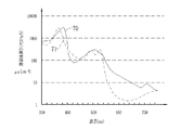
相関関係記憶部61は、第1及び第2輝度比S1/S3,S2/S3と、血管中の酸素飽和度及び血管深さとの相関関係を記憶している。この相関関係は、血管が図5に示すヘモグロビンの吸光係数を有する場合の相関関係であり、これまでの診断等で蓄積された多数の第1〜第3狭帯域光画像データを分析することにより得られたものである。図5に示すように、血管中のヘモグロビンは、照射する光の波長によって吸光係数μaが変化する吸光特性を持っている。吸光係数μaは、ヘモグロビンの光の吸収の大きさである吸光度を表すもので、ヘモグロビンに照射された光の減衰状況を表すI0exp(−μa×x)の式の係数である。ここで、I0は光源装置から被写体組織に照射される光の強度であり、x(cm)は被写体組織内の血管までの深さである。
The
また、酸素と結合していない還元ヘモグロビン70と、酸素と結合した酸化ヘモグロビン71は、異なる吸光特性を持っており、同じ吸光度(吸光係数μa)を示す等吸収点(図5における各ヘモグロビン70,71の交点)を除いて、吸光度に差が生じる。吸光度に差があると、同じ血管に対して、同じ強度かつ同じ波長の光を照射しても、輝度値が変化する。また、同じ強度の光を照射しても、波長が異なれば吸光係数μaが変わるので、輝度値が変化する。
Further, the reduced
以上のようなヘモグロビンの吸光特性を鑑みると、酸素飽和度が同じでも、波長が異なれば吸光度も異なり、粘膜中の深達度も異なる。したがって、第1狭帯域光N1、N2のように、ともに各ヘモグロビン70,71の吸光度に差があり、かつ、その差の大きさが異なる2つの波長帯域の光を利用して、両者の輝度値を比較することで、酸素飽和度と血管深さの2つの情報を同時に得ることができる。
In view of the light absorption characteristics of hemoglobin as described above, even if the oxygen saturation is the same, the absorbance is different and the depth of penetration in the mucous membrane is different if the wavelength is different. Therefore, as in the first narrow-band light N1, N2, the light intensity of the two
特許2648494号公報に記載されているように、ヘモグロビン70,71の各吸光度に差が生じる1つの波長域の光を用いて、その輝度値から酸素飽和度を測定する方法は従来から行われているが、1つの光の輝度値から求めた酸素飽和度の測定値は、血管深さによる影響を受けるため、精度の高いものではなかった。上記2つの波長帯域の光である第1狭帯域光N1、N2を利用する本発明の方法によれば、酸素飽和度情報に加えて、血管深さ情報も取得できるため、血管深さによる影響が除去された酸素飽和度の測定値が得られる。
As described in Japanese Patent No. 2648494, a method for measuring the oxygen saturation from the luminance value using light of one wavelength range in which the absorbances of the
また、本例においては、第1狭帯域光N1、N2として、青色領域の狭帯域光を使用している。青色領域の光が選択される理由は、腫瘍の良悪鑑別などの病変部の診断においては、中深層よりも表層血管の性状の把握が重要である場合が多く、表層血管の性状を詳細に把握できる観察方法が望まれているためである。こうした要請に応えるため、本例においては、深達度が浅く、表層血管の情報を良好に取得できる青色領域の光が採用される。 In this example, narrow band light in a blue region is used as the first narrow band light N1 and N2. The reason why light in the blue region is selected is that it is often more important to understand the properties of the superficial blood vessels than the mid-deep layer in the diagnosis of lesions such as tumor benign / bad discrimination. This is because an observation method that can be grasped is desired. In order to meet such a demand, in this example, light in a blue region is employed that has a low depth of penetration and can acquire information on the superficial blood vessels well.
そして、狭帯域光が使用される理由は、次のとおりである。図5に示すヘモグロビンの吸光スペクトルで明らかなように、青色領域においては、緑色領域や赤色領域と比較して、吸光度の変化が急峻であり、波長が少しずれると、吸光度が大きく変化する。また、各ヘモグロビン70、71の吸光度の大小関係に逆転が生じる等吸収点の間隔も狭い。波長帯域が広いと、大小関係が逆転する2つの領域の信号が混合して、輝度値が平均化されてしまうため、精度の高い情報が得られない。そのため、青色領域の光を利用して表層血管の血管情報を得るためには、2つの等吸収点の間隔に近い幅の波長帯域、好ましくは、2つの等吸収点の間隔に収まる波長帯域を持つ狭い狭帯域光を用いる必要がある。
The reason why the narrow band light is used is as follows. As apparent from the absorption spectrum of hemoglobin shown in FIG. 5, in the blue region, the change in absorbance is steep compared to the green region and red region, and the absorbance changes greatly when the wavelength is slightly shifted. Further, the interval between the isosbestic points where the magnitude relationship between the absorbances of the
また、図5に示すヘモグロビンの吸光スペクトルで明らかなように、波長が450nmを境に長波長側においては吸光係数が急激に落ち込む。吸光係数が高いほど、血管領域とそれ以外の領域の信号値の差が大きくなるため、血管情報を高い精度で取得することができる。そのため、本例においては、第1狭帯域光N1として、中心波長が450nm以下の波長帯域の光を使用している。なお、第1狭帯域光N1に加えて、第2狭帯域光N2についても中心波長が450nm以下の光を使用してもよい。 Further, as apparent from the absorption spectrum of hemoglobin shown in FIG. 5, the extinction coefficient drastically falls on the long wavelength side with the wavelength of 450 nm as a boundary. The higher the extinction coefficient, the greater the difference in signal value between the blood vessel region and the other region, so blood vessel information can be acquired with high accuracy. Therefore, in this example, light having a wavelength band with a center wavelength of 450 nm or less is used as the first narrowband light N1. In addition to the first narrowband light N1, the second narrowband light N2 may use light having a center wavelength of 450 nm or less.
また、表層血管は、中深層血管と比較して細いため、照射される光量が不足しがちであり、表層血管を観察する場合には、光量が大きな光源が適している。こうした理由から、本例では、狭帯域でかつ高い光量の光を発することが可能な半導体光源を採用している。また、第3狭帯域光N3については、参照光であるので、本例においては、各ヘモグロビン70,71の吸光度に差が生じない等吸収点(波長405nm)を中心波長とする400±10nmの波長帯域の光が利用される。
Further, since the surface blood vessels are thinner than the middle-deep blood vessels, the amount of light to be irradiated tends to be insufficient, and a light source with a large amount of light is suitable for observing the surface blood vessels. For this reason, in this example, a semiconductor light source capable of emitting a narrow band and a high amount of light is employed. In addition, since the third narrowband light N3 is a reference light, in this example, 400 ± 10 nm having a center wavelength of an isosbestic point (wavelength 405 nm) that does not cause a difference in absorbance between the
相関関係記憶部61は、図6に示すように、第1及び第2輝度比S1/S3,S2/S3を表す輝度座標系66の座標と、酸素飽和度及び血管深さを表す血管情報座標系67の座標との対応付けによって、相関関係を記憶している。輝度座標系66はXY座標系であり、X軸は第1輝度比S1/S3を、Y軸は第2輝度比S2/S3を表している。血管情報座標系67は輝度座標系66上に設けられたUV座標系であり、U軸は血管深さを、V軸は酸素飽和度を表している。U軸は、血管深さが輝度座標系66に対して正の相関関係があることから、正の傾きを有している。このU軸に関して、右斜め上に行くほど血管は浅いことを、左斜め下に行くほど血管が深いことを示している。一方、V軸は、酸素飽和度が輝度座標系66に対して負の相関関係を有することから、負の傾きを有している。このV軸に関して、左斜め上に行くほど酸素飽和度が低いことを、右斜め下に行くほど酸素飽和度が高いことを示している。
As shown in FIG. 6, the
また、血管情報座標系67においては、U軸とV軸とは交点Pで直交している。これは、第1狭帯域光N1の照射時と第2狭帯域光N2の照射時とで吸光の大小関係が逆転しているためである。即ち、図5に示すように、波長が440±10nmである第1狭帯域光N1を照射した場合には、還元ヘモグロビン70の吸光係数は、酸素飽和度が高い酸化ヘモグロビン71の吸光係数よりも大きくなるのに対して、波長が470±10nmである第2狭帯域光N2を照射した場合には、酸化ヘモグロビン71の吸光係数のほうが還元ヘモグロビン70の吸光係数よりも大きくなっているため、吸光の大小関係が逆転している。なお、第1〜第3狭帯域光N1〜N3に代えて、吸光の大小関係が逆転しない狭帯域光を照射したときには、U軸とV軸とは直交しなくなる。また、波長が400±10nmである第3狭帯域光N3を照射したときには、酸化ヘモグロビンと還元ヘモグロビンの吸光係数はほぼ等しくなっている。
In the blood vessel information coordinate system 67, the U axis and the V axis are orthogonal to each other at an intersection point P. This is because the magnitude relationship of light absorption is reversed between when the first narrowband light N1 is irradiated and when the second narrowband light N2 is irradiated. That is, as shown in FIG. 5, when the first narrowband light N1 having a wavelength of 440 ± 10 nm is irradiated, the extinction coefficient of reduced
血管深さ−酸素飽和度算出部62は、相関関係記憶部61の相関関係に基づき、輝度比算出部60で算出された第1及び第2輝度比S1/S3,S2/S3に対応する酸素飽和度と血管深さを特定する。ここで、輝度比算出部60で算出された第1及び第2輝度比S1/S3,S2/S3のうち、血管領域内の所定画素についての第1輝度比をS1*/S3*とし、第2輝度比をS2*/S3*とする。
The blood vessel depth-oxygen
血管深さ−酸素飽和度算出部62は、図7(A)に示すように、輝度座標系66において、第1及び第2輝度比S1*/S3*,S2*/S3*に対応する座標(X*,Y*)を特定する。座標(X*,Y*)が特定されたら、図7(B)に示すように、血管情報座標系67において、座標(X*,Y*)に対応する座標(U*,V*)を特定する。これにより、血管領域内の所定位置の画素について、血管深さ情報U*及び酸素飽和度情報V*が求まる。
As shown in FIG. 7A, the blood vessel depth-oxygen
血管深さ画像生成部63は、血管深さの程度に応じてカラー情報が割り当てられたカラーマップ63a(CM(Color Map))を備えている。カラーマップ63aには、例えば、血管深さが表層であるときには青、中層であるときには緑、深層であるときには赤というように、血管深さの程度に応じて、明瞭に区別することができる色が割り当てられている。血管深さ画像生成部63は、カラーマップ63aから、血管深さ−酸素飽和度算出部62で算出された血管深さ情報U*に対応するカラー情報を特定する。
The blood vessel depth
血管深さ画像生成部63は、血管領域内の全ての画素についてカラー情報が特定されると、そのカラー情報に基づいて、血管深さの情報が反映された血管深さ画像データを生成する。生成された血管深さ画像データは再度フレームメモリ56に記憶される。なお、カラー情報は、広帯域光画像データにではなく、第1〜第3狭帯域画像データのいずれか、あるいはこれらを合成した合成画像に対して反映させてもよい。
When the color information is specified for all the pixels in the blood vessel region, the blood vessel depth
酸素飽和度画像生成部64は、酸素飽和度の程度に応じてカラー情報が割り当てられたカラーマップ64a(CM(Color Map))を備えている。カラーマップ64aには、例えば、低酸素飽和度であるときにはシアン、中酸素飽和度であるときにはマゼンダ、光酸素飽和度であるときにはイエローというように、酸素飽和度の程度に応じて、明瞭に区別することができる色が割り当てられている。酸素飽和度画像生成部64は、血管深さ画像生成部と同様に、カラーマップ64aから血管深さ−酸素飽和度算出部で算出された酸素飽和度情報V*に対応するカラー情報を特定する。そして、このカラー情報に基づいて、酸素飽和度画像データが生成される。生成された酸素飽和度画像データは、血管深さ画像データと同様、フレームメモリ56に記憶される。
The oxygen saturation
表示制御回路58は、フレームメモリ56から1又は複数の画像を読み出し、読み出した画像をモニタ14に表示する。画像の表示形態としては様々なパターンが考えられる。例えば、図8に示すように、モニタ14の一方の側に広帯域画像72を表示させ、他方の側に、画像切替SW68(図2参照)により選択された血管深さ画像73または酸素飽和度画像74のいずれかを表示させるようにしてもよい。図8の血管深さ画像73では、血管画像75は表層血管を示す青色で、血管画像76は中層血管を示す緑色で、血管画像77は深層血管を示す赤色で表されている。また、酸素飽和度画像74では、血管画像80は低酸素飽和度を示すシアンで、血管画像81は中酸素飽和度を示すマゼンダで、血管画像82は高酸素飽和度を示すイエローで表されている。
The
図8に対して、図9に示すように、血管深さ画像73及び酸素飽和度画像74の両方を同時に表示するようにしてもよい。なお、図10に示すように、血管深さ画像73及び酸素飽和度画像74を表示せず、広帯域画像72のうち所定の血管画像85を指定し、その指定した血管画像85について血管深さ(D(Depth))及び酸素飽和度(StO2(Saturated Oxygen))を文字情報として表示するようにしてもよい。
In contrast to FIG. 8, as shown in FIG. 9, both the blood
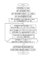
次に、血管深さ−酸素飽和度情報を算出する手順と、それら情報を反映した血管深さ画像及び酸素飽和度画像を生成する手順を、図11に示すフローチャートを用いて説明する。まず、コンソール23の操作により、通常光画像モードから特殊光画像モードに切り替える。
Next, a procedure for calculating blood vessel depth-oxygen saturation information and a procedure for generating a blood vessel depth image and an oxygen saturation image reflecting the information will be described with reference to the flowchart shown in FIG. First, the normal light image mode is switched to the special light image mode by operating the
特殊光画像モードに切り替えられると、コントローラー59からシャッター駆動部32に対して照射停止信号が送られる。これに従って、シャッター駆動部32は、シャッター31を退避位置から挿入位置に移動させ、体腔内への広帯域光BBの照射を停止する。広帯域光BBの照射が停止されると、コントローラー59から光源切替部37に対して照射開始指示が送られる。
When switching to the special light image mode, an irradiation stop signal is sent from the
この照射開始指示に従って、光源切替部37は、第1狭帯域光源33をONにし、第1狭帯域光N1を体腔内に照射する。第1狭帯域光N1が体腔内に照射されると、コントローラー59から撮像駆動部46に対して撮像指示が送られる。これにより、第1狭帯域光N1が照射された状態で撮像が行なわれ、第1狭帯域撮像信号が得られる。そして、同様にして、第2狭帯域光N2及び第3狭帯域光N3を体腔内に照射して撮像することによって、第2及び第3狭帯域撮像信号を取得する。
In accordance with this irradiation start instruction, the light
ここで、第1〜第3狭帯域光N1〜N3を照射したときには、光量検出器33b,34b,35bによってそれぞれの光量値L1,L2,L3が検出される。検出された光量値L1,L2,L3は、モニタリング部41を介して、DSP55とに送られる。
Here, when the first to third narrowband lights N1 to N3 are irradiated, the
そして、DSP55内の信号補正部55aは、光源装置13内で検出された第1〜第3狭帯域光N1〜N3の光量値L1,L2,L3に基づいて、第1〜第3狭帯域撮像信号に、第1〜第3狭帯域光N1〜N3の光量の変動(または第1光量比L1/L3及び第2光量比L2/L3の変動)を補正する補正処理を施す。そして、DSP55では、補正処理後の第1〜第3狭帯域撮像信号から第1〜第3狭帯域画像データを作成する。作成された第1〜第3狭帯域画像データは、光量値対応付け部55bによって光量値L1,L2,L3と対応付けられた上で、フレームメモリ56に記憶される。なお、光量検出器33b,34b,35bで検出された光量値L1,L2,L3は、光量値対応付け部55bによって第1〜第3狭帯域画像データと対応付けられて、フレームメモリ56に記憶される。
Then, the
フレームメモリ56に第1〜第3狭帯域画像データが記憶されたら、輝度比算出部60は、第1狭帯域画像データ、第2狭帯域画像データ、第3狭帯域画像データの3つの画像データから、血管を含む血管領域を特定する。そして、血管領域内の同じ位置の画素について、第1及び第3狭帯域画像データ間の第1輝度比S1*/S3*と、第2及び第3狭帯域画像データ間の第2輝度比S2*/S3*が算出される。
When the first to third narrowband image data is stored in the
次に、血管深さ−酸素飽和度算出部62は、相関関係記憶部61の相関関係に基づいて、第1及び第2輝度比S1*/S3*,S2*/S3*に対応する輝度座標系の座標(X*,Y*)を特定する。さらに、座標(X*,Y*)に対応する血管情報座標系の座標(U*,V*)を特定することにより、血管領域内の所定画素についての血管深さ情報U*及び酸素飽和度情報V*が求められる。
Next, the blood vessel depth-oxygen
血管深さ情報U*及び酸素飽和度情報V*が求められると、血管深さ情報U*に対応するカラー情報が血管深さ画像生成部のCM63aから特定されるとともに、酸素飽和度情報V*に対応するカラー情報が酸素飽和度画像生成部のCM64aから特定される。特定されたカラー情報は、プロセッサ装置12内のRAM(図示省略)に記憶される。
When the blood vessel depth information U * and the oxygen saturation information V * are obtained, color information corresponding to the blood vessel depth information U * is specified from the
そして、カラー情報がRAMに記憶されると、血管領域内の全ての画素について、上述した手順で、血管深さ情報U*及び酸素飽和度情報V*を求めるとともに、それら血管深さ情報U*及び酸素飽和度情報V*に対応するカラー情報を特定する。 When the color information is stored in the RAM, the blood vessel depth information U * and the oxygen saturation information V * are obtained for all the pixels in the blood vessel region by the above-described procedure, and the blood vessel depth information U * is obtained. And color information corresponding to the oxygen saturation information V * is specified.
そして、血管領域内の全ての画素について血管深さ情報及び酸素飽和度情報とそれら情報に対応するカラー情報が得られると、血管深さ画像生成部63は、RAMに記憶されたカラー情報に基づいて、血管深さ画像データを生成する。また、酸素飽和度画像生成部64は、血管深さ画像と同様にして、酸素飽和度画像データを生成する。生成された血管深さ画像データ及び酸素飽和度画像データは、再度フレームメモリ56に記憶される。そして、表示制御回路58は、フレームメモリ56から、血管深さ画像データ及び酸素飽和度画像データを読み出し、これら読み出した画像データに基づいて、血管深さ画像及び酸素飽和度画像をモニタ14に表示する。
When blood vessel depth information and oxygen saturation information and color information corresponding to the information are obtained for all the pixels in the blood vessel region, the blood vessel depth
本発明の第2実施形態では、血管深さ画像に代えて、血管の血液量を画像化した血液量画像を生成する。図12に示すように、第2実施形態の電子内視鏡システム100では、光源装置113の構成が第1実施形態の光源装置13と異なっている。また、電子内視鏡11内の撮像制御部46の動作が第1実施形態と異なっている。さらに、プロセッサ装置12においては、DSPの信号補正部55aでの補正処理が第1実施形態と異なり、また、血管画像生成部157が第1実施形態の血管画像生成部57と異なっている。それ以外については、第1実施形態と同様であるので、第1実施形態と異なる部分についてのみ以下で説明する。
In the second embodiment of the present invention, a blood volume image obtained by imaging the blood volume of a blood vessel is generated instead of the blood vessel depth image. As shown in FIG. 12, in the
第2実施形態の光源装置113は、白色光Wを発光する白色光光源ユニット120と、青色狭帯域光BNを発する青色狭帯域光源121と、白色光光源ユニット120と青色狭帯域光源121のON・OFFを切り替える光源切替部122と、白色光Wと青色狭帯域光BNの光量をモニタリングするモニタリング部123とを備えている。
The
白色光光源ユニット120は、中心波長445nmの励起光を発する励起光光源120aと、励起光によって蛍光を発する蛍光体120bとを有する。励起光光源120aはレーザーダイオードなどの半導体光源で構成される。蛍光体120bは、励起光の一部を吸収して緑色〜黄色に励起発光する複数種の蛍光物質(例えばYAG系蛍光物質、或いはBAM(BaMgAl10O17)等の蛍光物質)を含んで構成される。蛍光体120bから発せられる緑色〜黄色の励起発光光(蛍光)は、蛍光体120bにより吸収されず透過した第2狭帯域光N2と合波することで、白色光Wが生成される。生成された白色光Wは、集光レンズ39を通して、白色光用光ファイバ130に入射する。
The white
青色狭帯域光源121はレーザーダイオードなどの半導体光源で構成され、中心波長473nmの青色狭帯域光BNを発する。この青色狭帯域光BNは、血中ヘモグロビンの酸素飽和度を測定するために用いられる。青色狭帯域光源121からの青色狭帯域光BNは、青色狭帯域光用光ファイバ131に入射する。
The blue narrow band
カプラー36は、電子内視鏡内のライトガイド43と、白色光用光ファイバ130及び青色狭帯域光用光ファイバ131とを連結する。これにより、白色光W又は青色狭帯域光BNを、ライトガイド43に入射させることが可能となる。
The
光源切替部122はプロセッサ装置内のコントローラ59に接続されており、コントローラー59からの指示に基づいて、励起光光源120a及び青色狭帯域光源121をON(点灯)またはOFF(消灯)に切り替える。第2実施形態では、通常光画像モードに設定されている場合には、励起光光源120aが常時ONにされる一方、青色狭帯域光源121は常時OFFにされる。したがって、被検体内には白色光Wのみが照射される。これに対して、特殊光画像モードに設定されている場合には、励起光光源120aと青色狭帯域光源121は、交互にONにされる。したがって、被検体内には、白色光Wと青色狭帯域光NBが交互に照射される。
The light
モニタリング部123は、白色光用光ファイバ130及び青色狭帯域光用光ファイバ131に取り付けられた光量検出器130a,131aからの検出信号に基づいて、白色光W及び青色狭帯域光BNの光量をモニタリングする。このモニタリング結果は、DSP内の信号補正部55aに送られる。
The
第2実施形態の撮像制御部46では、特殊光画像モードに設定されている場合には、第1実施形態と異なる制御が行われる。第2実施形態では、図13に示すように、青色狭帯域光BNが被検体に照射されたときに、1フレーム期間内で、青色狭帯域光BNを光電変換して得られる電荷を蓄積するステップと、蓄積した電荷を読み出すステップの合計2ステップが行われる。その後に、白色光Wが照射されたときには、1フレーム期間内で、白色光Wを光電変換して得られる電荷を蓄積するステップと、蓄積した電荷を読み出すステップの合計2ステップが行われる。これら合計2フレームの撮像制御は、特殊光画像モードに設定されている間、繰り返し行われる。
In the
なお、青色狭帯域光BNを撮像したときに得られる撮像信号は、CCD44のB画素から出力される青色信号B1と、G画素から出力される緑色信号G1と、R画素から出力される赤色信号R1とからなる。また、白色光Wを照射したときに得られる撮像信号は、B画素から出力される青色信号B2と、G画素から出力される緑色信号G2と、R画素から出力される赤色信号R2とからなる。
Note that the imaging signal obtained when imaging the blue narrowband light BN is the blue signal B1 output from the B pixel of the
第2実施形態におけるプロセッサ装置内の信号補正部55aでは、血液量及び酸素飽和度の算出に使用される青色信号B1、緑色信号G2、赤色信号R2に対して、白色光W及び青色狭帯域光BNの光量の変動による信号値の変動を補正する補正処理を施す。この信号補正部55aは、光源装置113内で検出した白色光W及び青色狭帯域光BNのモニタリング結果に基づいて、以下の補正式により、青色信号B1、緑色信号G2、赤色信号R2の全画素を補正する。
B1´=c1(Wの光量、BNの光量)×B1
G2´=c2(Wの光量、BNの光量)×G2
R2´=c3(Wの光量、BNの光量)×R2
ここで、B1´、G2´、R2´は、補正後の青色信号、緑色信号、赤色信号を示している。c1、c2、c3は、白色光Wの光量、青色狭帯域光BNの光量によって決められる補正係数である。これら補正係数c1、c2、c3については、第1実施形態と同様、反射スペクトルが既知の基準被写体を用いて算出される。なお、以下の説明においては、B1´、G2´、R2´は、簡略化のため、「´」を除いたB1、G2、R2で表す。
In the
B1 ′ = c1 (W light quantity, BN light quantity) × B1
G2 ′ = c2 (W light quantity, BN light quantity) × G2
R2 ′ = c3 (W light quantity, BN light quantity) × R2
Here, B1 ′, G2 ′, and R2 ′ indicate the corrected blue signal, green signal, and red signal. c1, c2, and c3 are correction coefficients determined by the light amount of the white light W and the light amount of the blue narrow band light BN. These correction coefficients c1, c2, and c3 are calculated using a reference subject whose reflection spectrum is known, as in the first embodiment. In the following description, B1 ′, G2 ′, and R2 ′ are represented by B1, G2, and R2 excluding “′” for simplification.
第2実施形態におけるプロセッサ装置内の血管画像生成部157は、電子内視鏡11から入力される撮像信号に基づき被検体の血液量及び血中ヘモグロビンの酸素飽和度の情報を算出するとともに、算出した血液量を疑似カラー画像化した血液量画像と酸素飽和度を疑似カラー画像化した酸素飽和度画像を生成する。血管画像生成部157は、輝度比算出部160と、相関関係記憶部161と、血液量及び酸素飽和度算出部162と、血液量画像生成部163と、酸素飽和度画像生成部164とを備えている。
The blood vessel
輝度比算出部160は、青色狭帯域光BNの撮像時に得られる撮像信号と白色光Wの撮像時に得られる画像信号において、同じ位置にある画素間の輝度比を算出する。輝度比は画像信号の全ての画素に対して算出される。第2実施形態では、輝度比算出部160は、青色信号B1と緑色信号G2との輝度比B1/G2と、緑色信号G2と赤色信号R2との輝度比R2/G2とを求める。なお、輝度比は画像信号のうち血管部分の画素のみ求めてもよい。この場合、血管部分は、血管部分の画像信号とそれ以外の部分の画像信号との差に基づいて特定される。
The luminance
相関関係記憶部161は、輝度比B1/G2及びR2/G2と血液量及び酸素飽和度との相関関係を記憶している。輝度比と血液量との相関関係は、図14に示すように、輝度比R2/G2が大きくなればなるほど血液量も大きくなるように定義されている1次元テーブルで記憶されている。なお、輝度比R2/G2はlogスケールで記憶されている。
The
一方、輝度比と酸素飽和度との相関関係は、図15に示すように、二次元空間上に酸素飽和度の等高線を定義した2次元テーブルで記憶されている。この等高線の位置、形は光散乱の物理的なシミュレーションで得られ、血液量に応じて変わるように定義されている。例えば、血液量の変化があると、各等高線間の間隔が広くなったり、狭くなったりする。なお、輝度比B1/G2,R2/G2はlogスケールで記憶されている。 On the other hand, the correlation between the brightness ratio and the oxygen saturation is stored in a two-dimensional table in which contour lines of the oxygen saturation are defined in a two-dimensional space, as shown in FIG. The positions and shapes of the contour lines are obtained by a physical simulation of light scattering, and are defined to change according to the blood volume. For example, when there is a change in blood volume, the interval between the contour lines becomes wider or narrower. The luminance ratios B1 / G2 and R2 / G2 are stored on a log scale.
なお、上記相関関係は、図5に示すように、酸化ヘモグロビンや還元ヘモグロビンの吸光特性や光散乱特性と密接に関連性し合っている。図5が示すように、例えば、473nmのように吸光係数の差が大きい波長では、酸素飽和度の情報を取り易い。しかしながら、473nmの光に対応する信号を含む青色信号は、酸素飽和度だけでなく血液量にも依存度が高い。そこで、青色信号B1に加え、主として血液量に依存して変化する光に対応する赤色信号R2と、青色信号B1と赤色信号R2のリファレンス信号となる緑色信号G2とから得られる輝度比B1/G2及びR2/G2を用いることで、血液量に依存することなく、酸素飽和度を正確に求めることができる。 Note that, as shown in FIG. 5, the correlation is closely related to the light absorption characteristics and light scattering characteristics of oxyhemoglobin and reduced hemoglobin. As shown in FIG. 5, for example, at a wavelength with a large difference in extinction coefficient such as 473 nm, it is easy to obtain information on oxygen saturation. However, a blue signal including a signal corresponding to 473 nm light is highly dependent not only on oxygen saturation but also on blood volume. Therefore, in addition to the blue signal B1, a luminance ratio B1 / G2 obtained from a red signal R2 corresponding to light that changes mainly depending on the blood volume, and a green signal G2 that serves as a reference signal for the blue signal B1 and the red signal R2. And by using R2 / G2, the oxygen saturation can be accurately obtained without depending on the blood volume.
また、血中ヘモグロビンの吸光係数の波長依存性から、以下の3つのことが言える。
・波長470nm近辺(例えば、中心波長470nm±10nmの青色の波長領域)では酸素飽和度の変化に応じて吸光係数が大きく変化する。
・540〜580nmの緑色の波長範囲で平均すると、酸素飽和度の影響を受けにくい。
・590〜700nmの赤色の波長範囲では、酸素飽和度によって一見吸光係数が大きく変化するように見えるが、吸光係数の値自体が非常に小さいので、結果的に酸素飽和度の影響を受けにくい。
Moreover, the following three things can be said from the wavelength dependence of the extinction coefficient of blood hemoglobin.
In the vicinity of a wavelength of 470 nm (for example, a blue wavelength region having a central wavelength of 470 nm ± 10 nm), the extinction coefficient changes greatly according to the change in oxygen saturation.
-When averaged over the green wavelength range of 540 to 580 nm, it is less susceptible to oxygen saturation.
-In the red wavelength range of 590 to 700 nm, the extinction coefficient seems to change greatly depending on the oxygen saturation, but since the extinction coefficient itself is very small, it is hardly affected by the oxygen saturation as a result.
血液量及び酸素飽和度算出部162は、相関関係記憶部161に記憶された相関関係と輝度比算出部160で求めた輝度比B1/G2、R2/G2とを用いて、各画素における血液量及び酸素飽和度の両方を求める。血液量については、相関関係記憶部161の1次元テーブルにおいて輝度比算出部で求めた輝度比R2/G2に対応する値が、血液量となる。一方、酸素飽和度については、まず、図16に示すように、二次元空間において輝度比算出部84で求めた輝度比B1*/G2*、R2*/G2*に対応する対応点Pを特定する。
The blood volume and oxygen
そして、対応点Pが酸素飽和度=0%限界の下限ライン93と酸素飽和度=100%限界の上限ライン94との間にある場合、その対応点Pが位置する等高線が示すパーセント値が、酸素飽和度となる。例えば、図16の場合であれば、対応点Pが位置する等高線は60%を示しているため、この60%が酸素飽和度となる。なお、対応点が下限ライン93と上限ライン94との間から外れている場合には、対応点が下限ライン93よりも上方に位置するときには酸素飽和度を0%とし、対応点が上限ライン94よりも下方に位置するときには酸素飽和度を100%とする。なお、対応点が下限ライン93と上限ライン94との間から外れている場合には、その画素における酸素飽和度の信頼度を下げて表示しないようにしてもよい。
When the corresponding point P is between the oxygen saturation = 0%
血液量画像生成部163は、血液量及び酸素飽和度算出部162で求めた血液量を疑似カラーで表した血液量画像を生成する。血液量画像は、輝度Yと色差信号Cb,Crからなる映像信号で構成される。輝度Yには、緑色信号G2が割り当てられる。この緑色信号G2は、ヘモグロビンによる吸収がやや強い波長帯域の反射光に対応しているので、これに基づく画像からは粘膜の凹凸や血管などを視認できる。したがって、緑色信号G2を輝度に割り当てることで、疑似カラー画像の全体的な明るさを定義することができる。
The blood volume
一方、色差信号Cb,Crは、CM(カラーマップ)163aに従って、血液量に応じた信号値が割り当てられる。CM163aは、色差信号Cbについては血液量が大きくなるほど信号値が低下するように定義され、色差信号Crについては血液量が大きくなるほど信号値が増加するように定義されている。したがって、血液量画像は、血液量が多いところでは赤味が増加し、血液量が低くなるにつれて赤味の彩度が下がりモノクロに近づいていく。
On the other hand, the color difference signals Cb and Cr are assigned signal values according to the blood volume according to the CM (color map) 163a. The
酸素飽和度画像生成部164は、血液量及び酸素飽和度算出部162で求めた酸素飽和度を疑似カラーで表した酸素飽和度画像を生成する。酸素飽和度画像は、血液量画像と同様、輝度Yと色差信号Cb,Crからなる映像信号で構成される。輝度Yには、通常光画像信号の緑色信号G2が割り当てられる。色差信号Cb,Crは、CM(カラーマップ)164aに従い、酸素飽和度に応じた信号値が割り当てられる。
The oxygen saturation
CM164aは、高酸素飽和度下では色差信号Crの信号値が正、色差信号Cbの信号値が負となるように定義され、低酸素飽和度下では、反対に色差信号Crの信号値が負、色差信号Cbの信号値が正となるように定義されている。そして、中酸素飽和度下において、色差信号Crの信号値と色差信号Cbの信号値の大小関係が逆転するように定義されている。したがって、酸素飽和度が低い方から高い方に行くにつれて、酸素飽和度画像の色味は青→水色→緑→黄色→橙→赤と変化するようになっている。
The
以上のように生成された血液量画像及び酸素飽和度画像はモニタ14に表示される。モニタ14での表示方法としては、酸素飽和度画像と血液量画像を縮小し、それら縮小した画像を並列して同時に表示してもよい。あるいは、画像切替SW68をユーザが操作することによって、酸素飽和度画像と血液量画像のいずれか一方を選択し、その選択した画像をモニタ14を表示するようにしてもよい。
The blood volume image and the oxygen saturation image generated as described above are displayed on the
ここで、血液量及び酸素飽和度の算出に際しては、信号補正部55aで白色光W及び青色狭帯域光BNの光量の変動を補正する補正処理が施された青色信号B1、緑色信号G2、赤色信号R2を用いている。これにより、補正処理後の青色信号B1、緑色信号G2、赤色信号R2は標準状態時の信号値を保つことができ、また、それら信号から得られる輝度比B1/G2、R2/G2も標準状態時の信号値を保つことができる。したがって、このような輝度比B1/G2、R2/G2に基づいて血液量及び酸素飽和度の算出を行っているため、算出された血液量及び酸素飽和度は精度が低下することなく安定している。
Here, when calculating the blood volume and the oxygen saturation, the blue signal B1, the green signal G2, and the red signal that have been subjected to the correction processing for correcting the fluctuations of the light amounts of the white light W and the blue narrow band light BN by the
本発明の第3実施形態では、血管深さと酸素飽和度の算出に使用する3波長の光のうち、一部の光については、第1実施形態と同様に、半導体光源の光を使用する一方、残りの光については、キセノンランプなどの白色光源の広帯域光BBから波長分離した光を使用する。 In the third embodiment of the present invention, the light from the semiconductor light source is used for some of the three wavelengths of light used to calculate the blood vessel depth and oxygen saturation, as in the first embodiment. For the remaining light, light that is wavelength-separated from the broadband light BB of a white light source such as a xenon lamp is used.
図17に示すように、第3実施形態の電子内視鏡システム200では、光源装置213の構成が第1実施形態の光源装置13と異なっている。また、電子内視鏡11内のCCDの構成及び撮像制御部46の動作が第1実施形態と異なっている。さらに、プロセッサ装置12においては、信号補正部55aでの信号処理が第1実施形態と異なり、また、血管画像生成部57で使用する撮像信号が第1実施形態で使用する撮像信号と異なっている。それ以外については、第1実施形態と同様であるので、第1実施形態と異なる部分についてのみ以下で説明する。
As shown in FIG. 17, in the
光源装置213は、広帯域光BB(400〜700nm)を発する白色光源230と、この白色光源230からの広帯域光BBをB、R、Rの3色の光に色分離し、それら各色の光を順次ライトガイド43に供給するロータリフィルタ234と、中心波長が異なる2種類の第1及び第2青色狭帯域光BN1、BN2を発する半導体光源ユニット236と、ロータリフィルタ234とライトガイド43の間の光路L1上に第1及び第2青色狭帯域光BN1,BN2の光路L2を合流させる光合流部238と、所定のタイミングにおいて白色光源230とロータリフィルタ234との間の広帯域光BBの光路を塞ぐシャッタ板240と、広帯域光BB及び第1及び第2青色狭帯域光BN1,BN2の光量をモニタリングするモニタリング部250とを備えている。
The
白色光源230は、広帯域光BBを放射する光源本体230aと、広帯域光BBの光量を調整する絞り230bとを備えている。光源本体230aはキセノンランプ、ハロゲンランプ、メタルハライドなどから構成される。絞り230bの開度は、光量制御部260によって調節される。
The
図18に示すように、ロータリフィルタ234は、Bフィルタ部234a、Gフィルタ部234b、Rフィルタ部234cが選択的に広帯域光BBの光路に挿入されるように回転自在に設けられている。ロータリフィルタ234は、円板形状をしており、円周方向に3分割されて中心角が120°の扇型の領域に、それぞれBフィルタ部234a、Gフィルタ部234b、Rフィルタ部234cが設けられている。
As shown in FIG. 18, the
図19に示すように、Bフィルタ部234aは広帯域光BBから青色帯域のB光を透過させ、Gフィルタ部234bは広帯域光BBから緑色帯域のG光を透過させ、Rフィルタ部234cは広帯域光BBから赤色帯域のR光を透過させる。したがって、ロータリフィルタ234の回転によって、ロータリフィルタ234からはB光、G光、R光が順次出射する。
As shown in FIG. 19, the
半導体光源ユニット236は、第1及び第2のレーザ光源236a、236b、光ファイバ236c、236d、カプラー236e、光源制御部236fを有する。図19に示すように、第1のレーザ光源236aは中心波長445nmの第1青色狭帯域BN1を、第2のレーザ光源236bは中心波長473nmの第2青色狭帯域光BN2を発光する。第1のレーザ光源236aと第2のレーザ光源236bは、光源制御部236fの制御に従って、点灯及び消灯を行う。これにより、第1青色狭帯域光BN1と第2青色狭帯域光BN2を選択的に発生させる。なお、光源制御部236fはプロセッサ装置内のコントローラ59によって制御される。
The semiconductor
光ファイバ236c、236dは、各レーザ光源236a、236bが発する狭帯域光を導光して、カプラー236eに入射させる。カプラー236eは、各光ファイバ236c、236dから入射する第1及び第2青色狭帯域光BN1、BN2の光軸を一致させる。カプラー236eを出た第1又は第2青色狭帯域光BN1、BN2は、コリメータレンズ(図示省略)を通して、光合流部238に向けて出射する。
The
光合流部238はダイクロイックミラーであり、ロータリフィルタ234からの光はそのまま透過させる一方で、半導体光源ユニット236からの第1又は第2青色狭帯域光BN1、BN2は反射させてそれら光の光路L2を光路L1に一致させる。光合流部238を出た光は、集光レンズ242を通して、ライトガイド43に入射する。
The
図20に示すように、シャッタ板240は、240°の中心角を有し、広帯域光BBを遮光する遮光部240aと、残りの120°の中心角を有し、広帯域光BBを透過させる透過部240bとを備えている。シャッタ板240は回転自在に設けられており、回転することで、遮光部240aと透過部240bが交互に選択的に広帯域光BBの光路に挿入させるようになっている。
As shown in FIG. 20, the
シャッタ板240の回転動作は、通常光画像モードと特殊光画像モードとで異なっている。通常光画像モードにおいては、シャッタ板240は、遮光部240aが広帯域光BBの光路L1から退避し、透過部240bが光路L1に挿入された状態で停止している。したがって、広帯域光BBは、常時ロータリフイルタ234に入射する。これにより、広帯域光BBの光路L1に挿入されている、B、G、Rの各フイルタ部234a、234b、234cの種類に応じて、B光、G光、R光の三色の光が順次生成される。
The rotation operation of the
一方、特殊光画像モードにおいては、シャッタ板240は、透過部240bとGフイルタ部234bの回転位相が一致するように、ロータリフイルタ234と同じ速度で回転する。これにより、透過部240bが広帯域光BBの光路L1に挿入されて、遮光部240aが光路L1から退避している間、広帯域光BBはGフイルタ部234bを透過してG色光が生成される。これに対して、遮光部240aが広帯域光BBの光路L1に挿入されて、透過部240bが光路L1から退避している間、広帯域光BBが遮光される。広帯域光BBが遮光されている間に、第1及び第2のレーザ光源236a、236bが順次点灯して、第1及び第2青色狭帯域光BN1、BN2が電子内視鏡11に供給される。
On the other hand, in the special light image mode, the
モニタリング部250は、光源本体230aに取り付けられた光量検出器230c及び光ファイバ236c、236dに取り付けられた光量検出器236g、236hからの検出信号に基づいて、広帯域光BBと第1及び第2青色狭帯域光BN1、BN2の光量をモニタリングする。このモニタリング結果は、DSP内の信号補正部55aに送られる。
Based on detection signals from the
電子内視鏡内のCCD244は、上記第1及び第2実施形態と異なり、撮像面にマイクロカラーフィルタが設けられていないモノクロ撮像素子である。また、このCCD244の撮像を制御する撮像制御部46についても、上記第1及び第2実施形態と異なる動作を行う。
Unlike the first and second embodiments, the
通常光画像モードにおいては、図21(A)に示すように、B、G、Rの三色の像光を順次撮像して電荷を蓄積し、この蓄積した電荷に基づいて面順次撮像信号B、G、Rを順次出力する。この一連の動作は、通常観察モードに設定されている間、繰り返される。一方、特殊光画像モードにおいては、図21(B)に示すように、第1青色狭帯域光BN1、第2青色狭帯域光BN2、G光の3つの光の像光を順次撮像して電荷を蓄積し、この蓄積した電荷に基づいて面順次撮像信号N1、N2、Gを順次出力する。こうした動作が特殊光画像モードに設定されている間、繰り返される。 In the normal light image mode, as shown in FIG. 21A, image light of three colors B, G, and R is sequentially imaged and electric charges are accumulated, and a frame sequential image signal B based on the accumulated electric charges. , G, R are sequentially output. This series of operations is repeated while the normal observation mode is set. On the other hand, in the special light image mode, as shown in FIG. 21B, the image light of the three lights of the first blue narrow band light BN1, the second blue narrow band light BN2, and the G light is sequentially captured and charged. And sequentially outputs the image signals N1, N2, and G sequentially based on the accumulated charges. Such an operation is repeated while the special light image mode is set.
第3実施形態におけるプロセッサ装置内の信号補正部55aでは、血管深さ及び酸素飽和度の算出に使用される面順次撮像信号N1、N2、Gに対して、広帯域光BBと第1及び第2青色狭帯域光BN1、BN2の光量の変動による信号値の変動を補正する補正処理を施す。この信号補正部55aは、光源装置213内で検出した広帯域光BBと第1及び第2青色狭帯域光BN1、BN2のモニタリング結果に基づいて、以下の補正式により、面順次撮像信号N1、N2、Gの全画素を補正する。
N1´=c1(BBの光量、BN1、BN2の光量)×N1
N2´=c2(BBの光量、BN1、BN2の光量)×N2
G´=c3(BBの光量、BN1、BN2の光量)×G
ここで、N1´、N2´、G´は、補正後の面順次撮像信号N1、N2、Gを示している。c1、c2、c3は、広帯域光BBの光量、第1及び第2青色狭帯域光BN1、BN2の光量によって決められる補正係数である。これら補正係数c1、c2、c3については、第1実施形態と同様、反射スペクトルが既知の基準被写体を用いて算出される。なお、以下の説明においては、N1´、N2´、G´は、簡略化のため、「´」を除いたN1、N2、Gで表す。
In the
N1 ′ = c1 (BB light intensity, BN1, BN2 light intensity) × N1
N2 ′ = c2 (BB light amount, BN1, BN2 light amount) × N2
G ′ = c3 (BB light amount, BN1, BN2 light amount) × G
Here, N1 ′, N2 ′, and G ′ indicate the corrected surface sequential imaging signals N1, N2, and G, respectively. c1, c2, and c3 are correction coefficients determined by the light amount of the broadband light BB and the light amounts of the first and second blue narrow-band lights BN1 and BN2. These correction coefficients c1, c2, and c3 are calculated using a reference subject whose reflection spectrum is known, as in the first embodiment. In the following description, N1 ′, N2 ′, and G ′ are represented by N1, N2, and G excluding “′” for simplification.
プロセッサ装置内の血管画像生成部57は、第1実施形態と異なり、面順次撮像信号N1、N2、Gに基づいて、血管深さ画像及び酸素飽和度画像を生成する。第3実施形態では、第1実施形態の第1輝度比S1/S3に対応する輝度比としてN1/Gを用い、第1実施形態の第2輝度比S2/S3に対応する輝度比としてN2/Gを用いる。また、相関関係記憶部61には、輝度比N1/G及びN2/Gと血管深さ及び酸素飽和度との相関関係が記憶されている。それ以外については、第1実施形態と同様の手順で処理が行われる。
Unlike the first embodiment, the blood vessel
ここで、血管深さ及び酸素飽和度の算出に際しては、信号補正部55aで広帯域光BBと第1及び第2青色狭帯域光BN1、BN2の光量の変動を補正する補正処理が施された面順次撮像信号N1、N2、Gを用いている。これにより、補正処理後の面順次撮像信号N1、N2、Gは標準状態時の信号値となり、また、それら信号から得られる輝度比N1/G、N2/Gも標準状態時の信号値となる。したがって、このような輝度比N1/G、N2/Gに基づいて血管深さ及び酸素飽和度の算出を行っているため、算出された血管深さ及び酸素飽和度の精度を低下させることなく一定に保つことができる。
Here, when the blood vessel depth and the oxygen saturation are calculated, the
本発明の第4実施形態では、血液量と酸素飽和度の算出に使用する3波長の光のうち、一部の光については、第2実施形態と同様に、半導体光源の光を使用する一方、残りの光については、キセノンランプなどの白色光源の広帯域光BBから波長分離した光を使用する。 In the fourth embodiment of the present invention, the light of the semiconductor light source is used for some of the three wavelengths of light used for calculating the blood volume and oxygen saturation, as in the second embodiment. For the remaining light, light that is wavelength-separated from the broadband light BB of a white light source such as a xenon lamp is used.
図22に示すように、第4実施形態の電子内視鏡システム300では、光源装置313の構成が第2実施形態の光源装置113と異なっている。また、電子内視鏡11内のCCDの構成及び撮像制御部46の動作が第2実施形態と異なっている。さらに、プロセッサ装置12内においては、信号補正部55aでの信号処理が第2実施形態とは異なり、また、血管画像生成部157で使用する撮像信号が第2実施形態で使用する撮像信号と異なっている。それ以外については、第2実施形態と同様であるので、第2実施形態と異なる部分についてのみ以下で説明する。
As shown in FIG. 22, in the
光源装置313は、半導体光源ユニット336及びシャッタ板340の構成とシャッタ板340の回転動作が異なる以外は、第3実施形態の光源装置213と同様の構成を備えている。半導体光源ユニット336には、第3実施形態と異なり、中心波長473nmの第2青色狭帯域光BN2を発する第2のレーザ光源236bのみが設けられている。また、半導体光源ユニット236には、第2のレーザ光源236bの他に、第2青色狭帯域光BN2を光合流部238に向けて集光させる集光レンズ320と、第2レーザ光源236bの点灯及び消灯を行う光源制御部236fとが設けられている。
The
図23に示すように、シャッタ板340は、120°の中心角を有し、広帯域光BBを遮光する遮光部340aと、残りの240°の中心角を有し、広帯域光BBを透過させる透過部340bとを備えている。シャッタ板340は回転自在に設けられており、回転することで、遮光部340aと透過部340bが交互に選択的に広帯域光BBの光路に挿入させるようになっている。
As shown in FIG. 23, the
シャッタ板340の回転動作は、通常光画像モードと特殊光画像モードとで異なっている。通常光画像モードにおいては、シャッタ板340は、遮光部340aが広帯域光BBの光路L1から退避し、透過部340bが光路L1に挿入された状態で停止している。したがって、広帯域光BBは、常時ロータリフイルタ234に入射する。これにより、広帯域光BBの光路L1に挿入されている、B、G、Rの各フイルタ部234a、234b、234cの種類に応じて、B光、G光、R光の三色の光が順次生成される。
The rotation operation of the
一方、特殊光画像モードにおいては、シャッタ板340は、遮光部340aとBフイルタ部234aの回転位相が一致するように、ロータリフイルタ234と同じ速度で回転する。これにより、透過部340bが広帯域光BBの光路L1に挿入されて、遮光部340aが光路L1から退避している間、広帯域光BBはGフイルタ部234b、Rフィルタ234cを透過してG光、R光が生成される。これに対して、遮光部340aが広帯域光BBの光路L1に挿入されて、透過部340bが光路L1から退避している間、広帯域光BBが遮光される。広帯域光BBが遮光されている間に、第2のレーザ光源236bが点灯して、第2青色狭帯域光BN2が電子内視鏡11に供給される。
On the other hand, in the special light image mode, the
モニタリング部250は、光源本体230aに取り付けられた光量検出器23c及び第2のレーザ光源236bに取り付けられた光量検出器236hからの検出信号に基づいて、広帯域光BB及び第2青色狭帯域光BN2の光量をモニタリングする。このモニタリング結果は、DSP内の信号補正部55aに送られる。
Based on the detection signals from the light amount detector 23c attached to the
電子内視鏡内のCCD244は、上記第1及び第2実施形態と異なり、撮像面にマイクロカラーフィルタが設けられていないモノクロ撮像素子である。また、このCCD244の撮像を制御する撮像制御部46についても、上記第1及び第2実施形態と異なる動作を行う。
Unlike the first and second embodiments, the
通常光画像モードについては第3実施形態と同様である。一方、特殊光画像モードにおいては、図24に示すように、第2青色狭帯域光BN2、G光、R光の3つの光の像光を順次撮像して電荷を蓄積し、この蓄積した電荷に基づいて面順次撮像信号N2、G、Rを順次出力する。こうした動作が特殊光画像モードに設定されている間、繰り返される。 The normal light image mode is the same as in the third embodiment. On the other hand, in the special light image mode, as shown in FIG. 24, the image light of the three light beams of the second blue narrow band light BN2, G light, and R light is sequentially picked up to accumulate charges, and the accumulated charges The frame sequential imaging signals N2, G, and R are sequentially output based on the above. Such an operation is repeated while the special light image mode is set.
第4実施形態におけるプロセッサ装置内の信号補正部55aでは、血管深さ及び酸素飽和度の算出に使用される面順次撮像信号N2、G、Rに対して、広帯域光BBと第2青色狭帯域光BN2の光量の変動による信号値の変動を補正する補正処理を施す。この信号補正部55aは、光源装置313内で検出した広帯域光BBと第2青色狭帯域光BN2のモニタリング結果に基づいて、以下の補正式により、面順次撮像信号N2、G、Rの全画素を補正する。
N2´=c1(BBの光量、BN2の光量)×N2
G´=c2(BBの光量、BN2の光量)×G
R´=c3(BBの光量、BN2の光量)×R
ここで、N2´、G´、R´は、補正後の面順次撮像信号N2、G、Rを示している。c1、c2、c3は、広帯域光BBの光量及び第2青色狭帯域光BN2の光量によって決められる補正係数である。これら補正係数c1、c2、c3については、第1実施形態と同様、反射スペクトルが既知の基準被写体を用いて算出される。なお、以下の説明においては、N2´、G´、R´は、簡略化のため、「´」を除いたN2、G、Rで表す。
In the
N2 ′ = c1 (BB light amount, BN2 light amount) × N2
G ′ = c2 (light quantity of BB, light quantity of BN2) × G
R ′ = c3 (light quantity of BB, light quantity of BN2) × R
Here, N2 ′, G ′, and R ′ indicate the corrected surface sequential imaging signals N2, G, and R, respectively. c1, c2, and c3 are correction coefficients determined by the light amount of the broadband light BB and the light amount of the second blue narrowband light BN2. These correction coefficients c1, c2, and c3 are calculated using a reference subject whose reflection spectrum is known, as in the first embodiment. In the following description, N2 ′, G ′, and R ′ are represented by N2, G, and R excluding “′” for simplification.
プロセッサ装置内の血管画像生成部157は、第2実施形態と異なり、面順次撮像信号N2、G、Rに基づいて、血液量画像及び酸素飽和度画像を生成する。第4実施形態では、第2実施形態の第1輝度比B1/G2に対応する輝度比としてN2/Gを用い、第2実施形態の第2輝度比R2/G2に対応する輝度比としてR/Gを用いる。また、相関関係記憶部161には、輝度比N2/G及びR/Gと血管深さ及び酸素飽和度との相関関係が記憶されている。それ以外については、第2実施形態と同様の手順で処理が行われる。
Unlike the second embodiment, the blood vessel
ここで、血液量及び酸素飽和度の算出に際しては、信号補正部55aで広帯域光BBと第2青色狭帯域光BN2の光量の変動を補正する補正処理が施された面順次撮像信号N2、G、Rを用いている。これにより、補正処理後の面順次撮像信号N2、G、Rは標準状態時の信号値となり、また、それら信号から得られる輝度比N2/G、R/Gも標準状態時の信号値となる。したがって、このような輝度比N2/G、R/Gに基づいて血管深さ及び酸素飽和度の算出を行っているため、算出された血管深さ及び酸素飽和度の精度を低下させることなく一定に保つことができる。
Here, in the calculation of the blood volume and the oxygen saturation, the surface sequential imaging signals N2, G subjected to the correction processing for correcting the light amount fluctuations of the broadband light BB and the second blue narrowband light BN2 in the
上記第1〜第4実施形態では、DSPの信号補正部において、光源装置内でモニタリングした光の光量から決められる補正係数を用いて信号補正を行ったが、これに代えて、予め光源装置内で設定される光量指示値を使用し、この光量指示値に基づいて一意的に決められる補正係数を用いて信号補正を行ってもよい。 In the first to fourth embodiments, the signal correction unit of the DSP performs signal correction using a correction coefficient determined from the amount of light monitored in the light source device. Instead, in the light source device in advance. The signal correction may be performed using a correction coefficient uniquely determined based on the light quantity instruction value set in step (b).
上記第1〜第4実施形態では、光源装置内での光量のモニタリング結果に基づき、常時、血管深さ、血液量、酸素飽和度などの各種血管情報を得るための信号に、光量の変動を補正する補正処理を施したが、それら光量が短時間で大きく変動しなければ、内視鏡の使用前に行う較正処理で光量の変動量を求め、内視鏡の使用中は、その求めた変動量に基づいて信号処理補正を行ってもよい。なお、以下においては、第1実施形態の電子内視鏡システム10で内視鏡使用前の較正処理を行った場合について説明するが、第2〜第4実施形態の電子内視鏡システム100、200、300についても同様にして内視鏡使用前の較正処理を行うことができる。
In the first to fourth embodiments, fluctuations in the light amount are always applied to signals for obtaining various blood vessel information such as blood vessel depth, blood volume, and oxygen saturation based on the monitoring result of the light amount in the light source device. Although correction processing was performed, if these light amounts did not fluctuate significantly in a short time, the amount of light amount fluctuation was obtained by calibration processing performed before using the endoscope, and the amount of light obtained during the use of the endoscope was obtained. Signal processing correction may be performed based on the fluctuation amount. In the following, the case where the calibration process before using the endoscope is performed in the
図25に示すように、内視鏡使用前の較正処理では、内視鏡使用前に較正用の基準被写体402を撮像し、撮像により得られる画像信号を用いて較正を行なう。基準被写体402は、電子内視鏡11の先端部16aに装着可能な先端キャップ403の内側に設けられている。このように、先端キャップ403の内側に基準被写体402を設けることで、一定の距離・角度で撮影を行なうことができる。
As shown in FIG. 25, in the calibration process before using the endoscope, a
基準被写体402を用いた較正は以下のようにして行なわれる。まず、第1〜第3狭帯域光源33〜35を標準状態の光量比に設定した上で、基準被写体402を撮像する。これにより得られる第1〜第3狭帯域撮像信号間の画像信号比を、標準状態時における画像信号比としてプロセッサ装置内のRAM(図示省略)に記憶しておく。画像信号比は、第1及び第3狭帯域光を基準被写体402に照射したときに得られる第1輝度比と、第2及び第3狭帯域光を基準被写体402に照射したときに得られる第2輝度比とからなる。
Calibration using the
そして、実際に内視鏡を使用する時点で、再度基準被写体402に第1〜第3狭帯域光を照射して撮像する。これにより、第1〜第3較正用撮像信号が得られる。そして、DSP55内のずれ量算出部55cは、第1〜第3較正用撮像信号間の画像信号比と、RAMに記憶された標準状態時における画像信号比とから、第1〜第3較正用撮像信号間の画像信号比が標準状態時の画像信号比からどの程度ずれているかを示すずれ量を算出する。
Then, at the time when the endoscope is actually used, the
ずれ量算出部55cで求められた画像信号比のずれ量は、そのままDSP55内のずれ量記憶部55dに記憶されるとともに、光量制御部42内のずれ量記憶部42aに記憶される。そして、実際の内視鏡使用時の下では、光量制御部42は、ずれ量記憶部42aに記憶したずれ量に基づいて、第1〜第3狭帯域光N1〜N3の光量を調整する。また、DSP55の信号補正部55aは、ずれ量記憶部55dに記憶したずれ量に基づいて、第1〜第3狭帯域撮像信号を補正する。
The deviation amount of the image signal ratio obtained by the deviation
なお、上記においては、酸素飽和度の画像化を行ったが、これに代えて又は加えて、「血液量(酸化ヘモグロビンと還元ヘモグロビンの和)×酸素飽和度(%)」から求まる酸化ヘモグロビンインデックスの画像化や、「血液量×(100−酸素飽和度)(%)」から求まる還元ヘモグロビンインデックスの画像化を行ってもよい。 In the above, oxygen saturation was imaged, but instead or in addition, an oxygenated hemoglobin index determined from “blood volume (sum of oxidized hemoglobin and reduced hemoglobin) × oxygen saturation (%)” Or a reduced hemoglobin index obtained from “blood volume × (100−oxygen saturation) (%)” may be performed.
10,100,200,300 電子内視鏡システム
14 モニタ
30 広帯域光源
33b〜35b,130a,131a,230c,236g,236h 光量検出部
33〜35 第1〜第3狭帯域光源
41 光量比モニタリング部
44 CCD
55 DSP
55a 信号補正部
55b 光量値対応付け部
62 血管深さ−酸素飽和度算出部
120 白色光光源ユニット
121 青色狭帯域光源
123,250 モニタリング部
162 血液量−酸素飽和度算出部
230 白色光源
236,336 半導体光源ユニット
402 基準被写体
10, 100, 200, 300
55 DSP
55a
Claims (14)
前記第1〜第3の照明光が照射された被写体組織を撮像素子で撮像することによって第1〜第3撮像信号を取得する信号取得手段と、
前記第1〜第3の照明光の光量に基づいて、前記第1〜第3撮像信号を補正する信号補正手段と、
補正後の第1及び第3撮像信号間の第1輝度比と、補正後の第2及び第3撮像信号間の第2輝度比に基づいて、血管深さと酸素飽和度を求める血管情報取得手段とを備えていることを特徴とする電子内視鏡システム。 Reference light used for comparison between the first and second illumination lights, which have different wavelength bands and whose extinction coefficient changes according to the oxygen saturation of blood hemoglobin, and the first and second illumination lights Illuminating means for emitting a third illumination light toward the subject tissue;
Signal acquisition means for acquiring first to third imaging signals by imaging the subject tissue irradiated with the first to third illumination lights with an imaging element;
Signal correcting means for correcting the first to third imaging signals based on the light amounts of the first to third illumination lights;
Blood vessel information acquisition means for obtaining blood vessel depth and oxygen saturation based on the first luminance ratio between the corrected first and third imaging signals and the second luminance ratio between the corrected second and third imaging signals. And an electronic endoscope system.
前記第1〜第3の照明光が照射された被写体組織を撮像素子で撮像することによって第1〜第3撮像信号を取得する信号取得手段と、
前記第1〜第3の照明光の光量に基づいて、前記第1〜第3撮像信号を補正する信号補正手段と、
補正後の第1及び第3撮像信号間の第1輝度比と、補正後の第2及び第3撮像信号間の第2輝度比に基づいて、血液量と酸素飽和度を求める血管情報取得手段とを備えていることを特徴とする電子内視鏡システム。 Reference light used for comparison between the first and second illumination lights, which have different wavelength bands and whose extinction coefficient changes according to the oxygen saturation of blood hemoglobin, and the first and second illumination lights Illuminating means for emitting a third illumination light toward the subject tissue;
Signal acquisition means for acquiring first to third imaging signals by imaging the subject tissue irradiated with the first to third illumination lights with an imaging element;
Signal correcting means for correcting the first to third imaging signals based on the light amounts of the first to third illumination lights;
Blood vessel information acquisition means for obtaining blood volume and oxygen saturation based on the first luminance ratio between the corrected first and third imaging signals and the second luminance ratio between the corrected second and third imaging signals. And an electronic endoscope system.
前記信号補正手段は、前記光量検出手段が検出した光量に基づいて、前記第1〜第3撮像信号を補正することを特徴とする請求項1または2記載の電子内視鏡システム。 Comprising a light amount detection means for detecting the light amount of the first to third illumination light,
It said signal correction means, based on the amount of the light amount detecting unit detects the first to third image pickup signal according to claim 1 or 2 electronic endoscope system wherein a corrected.
前記第1〜第3の照明光が照射された基準被写体を撮像素子で撮像することによって第1〜第3較正用撮像信号を取得する較正用撮像信号取得手段と、
前記第1及び第3の照明光間の第1光量比に対応する、前記第1及び第3較正用撮像信号の第1撮像信号比と、前記第2及び第3の照明光間の第2光量比に対応する、前記第2及び第3較正用撮像信号の第2撮像信号比とに基づいて算出され、それぞれに対応する所定の標準撮像信号比とのずれ量を記憶するずれ量記憶手段とを備え、
前記信号補正部は、前記第1〜第3の照明光の光量の代わりに、前記ずれ量に基づいて、前記第1〜第3撮像信号を補正することを特徴とする請求項1ないし7いずれか1項記載の電子内視鏡システム。 A reference object with a known reflection spectrum;
An imaging signal acquisition unit for calibration that acquires the first to third calibration imaging signals by imaging the reference subject irradiated with the first to third illumination lights with an imaging device;
A first imaging signal ratio of the first and third calibration imaging signals corresponding to a first light quantity ratio between the first and third illumination lights and a second between the second and third illumination lights . A deviation amount storage means for calculating a deviation amount from a predetermined standard imaging signal ratio corresponding to each of the second imaging signal ratio of the second and third calibration imaging signals corresponding to the light amount ratio. And
The signal correction unit, instead of the first to third light amount of illumination light, on the basis of the shift amount, any claims 1 to 7, characterized in that to correct the first through third image pickup signal The electronic endoscope system according to claim 1.
信号取得手段が、被写体組織を撮像素子で撮像することによって第1〜第3撮像信号を取得するステップと、
信号補正手段が、前記第1〜第3の照明光の光量に基づいて、前記第1〜第3撮像信号を補正するステップと、
血管情報取得手段が、補正後の第1及び第3撮像信号間の第1輝度比と、補正後の第2及び第3撮像信号間の第2輝度比に基づいて、血管深さと酸素飽和度を求めるステップとを有することを特徴とする電子内視鏡システムの作動方法。 The illuminating means is used for comparing the first and second illumination light with the first and second illumination light having different wavelength bands and having an extinction coefficient that changes in accordance with the oxygen saturation level of blood hemoglobin. Emitting a third illumination light that is a reference light ,
A signal acquisition means for acquiring first to third imaging signals by imaging a subject tissue with an imaging device ;
Signal correcting means correcting the first to third imaging signals based on the light amounts of the first to third illumination lights ; and
The blood vessel information acquisition means determines the blood vessel depth and the oxygen saturation based on the corrected first luminance ratio between the first and third imaging signals and the corrected second luminance ratio between the second and third imaging signals. electronic endoscope system the operating method characterized by having a step of obtaining.
信号取得手段が、被写体組織を撮像素子で撮像することによって第1〜第3撮像信号を取得するステップと、
信号補正手段が、前記第1〜第3の照明光の光量に基づいて、前記第1〜第3撮像信号を補正するステップと、
血管情報取得手段が、補正後の第1及び第3撮像信号間の第1輝度比と、補正後の第2及び第3撮像信号間の第2輝度比に基づいて、血液量と酸素飽和度を求めるステップとを有することを特徴とする電子内視鏡システムの作動方法。 The illuminating means is used for comparing the first and second illumination light with the first and second illumination light having different wavelength bands and having an extinction coefficient that changes in accordance with the oxygen saturation level of blood hemoglobin. Emitting a third illumination light that is a reference light ,
A signal acquisition means for acquiring first to third imaging signals by imaging a subject tissue with an imaging device ;
Signal correcting means correcting the first to third imaging signals based on the light amounts of the first to third illumination lights ; and
The blood vessel information acquisition means determines the blood volume and oxygen saturation based on the corrected first luminance ratio between the first and third imaging signals and the corrected second luminance ratio between the second and third imaging signals. A method for operating the electronic endoscope system .
Priority Applications (1)
| Application Number | Priority Date | Filing Date | Title |
|---|---|---|---|
| JP2011179656A JP5616303B2 (en) | 2010-08-24 | 2011-08-19 | Electronic endoscope system and method for operating electronic endoscope system |
Applications Claiming Priority (3)
| Application Number | Priority Date | Filing Date | Title |
|---|---|---|---|
| JP2010187213 | 2010-08-24 | ||
| JP2010187213 | 2010-08-24 | ||
| JP2011179656A JP5616303B2 (en) | 2010-08-24 | 2011-08-19 | Electronic endoscope system and method for operating electronic endoscope system |
Publications (2)
| Publication Number | Publication Date |
|---|---|
| JP2012066065A JP2012066065A (en) | 2012-04-05 |
| JP5616303B2 true JP5616303B2 (en) | 2014-10-29 |
Family
ID=45698126
Family Applications (2)
| Application Number | Title | Priority Date | Filing Date |
|---|---|---|---|
| JP2011179656A Active JP5616303B2 (en) | 2010-08-24 | 2011-08-19 | Electronic endoscope system and method for operating electronic endoscope system |
| JP2011179657A Active JP5616304B2 (en) | 2010-08-24 | 2011-08-19 | Electronic endoscope system and method for operating electronic endoscope system |
Family Applications After (1)
| Application Number | Title | Priority Date | Filing Date |
|---|---|---|---|
| JP2011179657A Active JP5616304B2 (en) | 2010-08-24 | 2011-08-19 | Electronic endoscope system and method for operating electronic endoscope system |
Country Status (2)
| Country | Link |
|---|---|
| US (1) | US8535221B2 (en) |
| JP (2) | JP5616303B2 (en) |
Families Citing this family (37)
| Publication number | Priority date | Publication date | Assignee | Title |
|---|---|---|---|---|
| JP5654511B2 (en) * | 2012-03-14 | 2015-01-14 | 富士フイルム株式会社 | Endoscope system, processor device for endoscope system, and method for operating endoscope system |
| JP5362149B1 (en) * | 2012-03-30 | 2013-12-11 | オリンパスメディカルシステムズ株式会社 | Endoscope device |
| JP5774563B2 (en) * | 2012-09-04 | 2015-09-09 | 富士フイルム株式会社 | ENDOSCOPE SYSTEM, PROCESSOR DEVICE THEREOF, AND METHOD FOR OPERATING ENDOSCOPY SYSTEM |
| JP5698878B2 (en) * | 2013-02-12 | 2015-04-08 | オリンパスメディカルシステムズ株式会社 | Endoscope device |
| JP6128888B2 (en) * | 2013-02-27 | 2017-05-17 | オリンパス株式会社 | Image processing apparatus, image processing method, and image processing program |
| US9420967B2 (en) * | 2013-03-19 | 2016-08-23 | Surgisense Corporation | Apparatus, systems and methods for determining tissue oxygenation |
| EP2976989A4 (en) * | 2013-07-11 | 2017-03-15 | Olympus Corporation | Light source device |
| JP6099529B2 (en) * | 2013-09-11 | 2017-03-22 | 富士フイルム株式会社 | Endoscope system, processor device, light source device, and operation method |
| JP6140056B2 (en) * | 2013-09-26 | 2017-05-31 | 富士フイルム株式会社 | Endoscope system, processor device for endoscope system, method for operating endoscope system, method for operating processor device |
| JP5855619B2 (en) * | 2013-09-30 | 2016-02-09 | 富士フイルム株式会社 | Calibration method and endoscope system |
| JP6159817B2 (en) * | 2013-10-28 | 2017-07-05 | 富士フイルム株式会社 | Calibration method and endoscope system |
| JP6649260B2 (en) | 2014-02-04 | 2020-02-19 | コーニンクレッカ フィリップス エヌ ヴェKoninklijke Philips N.V. | Visualization of blood vessel depth and position and robot-guided visualization of blood vessel cross-section |
| JP6203088B2 (en) * | 2014-03-13 | 2017-09-27 | オリンパス株式会社 | Living body observation system |
| US10805511B2 (en) | 2014-05-01 | 2020-10-13 | Sony Corporation | Controlling a set of light sources by individual adjustment to output a desired light |
| JP6386889B2 (en) * | 2014-11-28 | 2018-09-05 | 富士フイルム株式会社 | Endoscope light source device, endoscope system and operating method thereof |
| JP6597635B2 (en) * | 2014-12-09 | 2019-10-30 | ソニー株式会社 | Illumination device, method of operating illumination device, and image acquisition system |
| JP6425995B2 (en) * | 2014-12-24 | 2018-11-21 | 富士フイルム株式会社 | Endoscope system and method of operating the same |
| CN106714660B (en) * | 2015-02-04 | 2018-12-28 | 奥林巴斯株式会社 | Endoscope apparatus |
| CA2985850C (en) * | 2015-06-09 | 2023-07-11 | Gen-Probe Incorporated | Methods and devices for calibrating and/or monitoring optical measurement devices |
| JPWO2017046857A1 (en) * | 2015-09-14 | 2018-07-05 | オリンパス株式会社 | Endoscope device |
| WO2017078085A1 (en) * | 2015-11-02 | 2017-05-11 | Hoya株式会社 | Endoscope system and analyzing device |
| JP6744712B2 (en) | 2015-12-17 | 2020-08-19 | 富士フイルム株式会社 | Endoscope system, processor device, and method of operating endoscope system |
| JP6408457B2 (en) * | 2015-12-22 | 2018-10-17 | 富士フイルム株式会社 | Endoscope system and method for operating endoscope system |
| JP6561000B2 (en) * | 2016-03-09 | 2019-08-14 | 富士フイルム株式会社 | Endoscope system and operating method thereof |
| JP6779025B2 (en) * | 2016-04-01 | 2020-11-04 | 富士フイルム株式会社 | Image processing device and its operation method, endoscope processor device and its operation method |
| WO2017221335A1 (en) * | 2016-06-21 | 2017-12-28 | オリンパス株式会社 | Image processing device, image processing method, and program |
| JP2018027201A (en) * | 2016-08-18 | 2018-02-22 | Hoya株式会社 | Light source device for electronic endoscope and electronic endoscope system |
| CA3057979A1 (en) | 2017-03-29 | 2018-10-04 | Graftworx, Inc. | Wearable device with multimodal diagnostics |
| CN110573056B (en) * | 2017-05-02 | 2021-11-30 | 奥林巴斯株式会社 | Endoscope system |
| CN111050629B (en) * | 2017-08-23 | 2022-09-06 | 富士胶片株式会社 | Endoscope system |
| EP3682239B1 (en) | 2017-09-13 | 2023-03-22 | Alio, Inc. | Systems and methods for detecting a periprosthetic infection |
| WO2019053804A1 (en) * | 2017-09-13 | 2019-03-21 | オリンパス株式会社 | Endoscopic apparatus, operation method of endoscopic apparatus, and program |
| KR102522203B1 (en) | 2017-12-01 | 2023-04-14 | 삼성전자주식회사 | Apparatus and method for measuring bio-information |
| WO2019172231A1 (en) * | 2018-03-06 | 2019-09-12 | 富士フイルム株式会社 | Medical image processing system and endoscope system |
| JP7163386B2 (en) * | 2018-06-19 | 2022-10-31 | オリンパス株式会社 | Endoscope device, method for operating endoscope device, and program for operating endoscope device |
| JP6615950B2 (en) * | 2018-07-05 | 2019-12-04 | 富士フイルム株式会社 | Endoscope system, processor device, operation method of endoscope system, and operation method of processor device |
| JP6916768B2 (en) | 2018-09-05 | 2021-08-11 | 富士フイルム株式会社 | Endoscope system |
Family Cites Families (22)
| Publication number | Priority date | Publication date | Assignee | Title |
|---|---|---|---|---|
| JP2648494B2 (en) | 1988-05-02 | 1997-08-27 | オリンパス光学工業株式会社 | Endoscope device |
| JPH0360646A (en) * | 1989-07-28 | 1991-03-15 | Shimadzu Corp | Oxygen saturation measuring device |
| JP2608828B2 (en) * | 1992-02-06 | 1997-05-14 | 日本光電工業株式会社 | Non-invasive oximeter |
| JP2001208985A (en) * | 2000-01-27 | 2001-08-03 | Olympus Optical Co Ltd | Endoscope device |
| EP1302152B1 (en) * | 2000-07-21 | 2013-03-20 | Olympus Corporation | Endoscope apparatus |
| US7711403B2 (en) * | 2001-04-05 | 2010-05-04 | Rhode Island Hospital | Non-invasive determination of blood components |
| JP2005131129A (en) * | 2003-10-30 | 2005-05-26 | Olympus Corp | Imaging device and endoscope apparatus |
| JP4566754B2 (en) * | 2005-01-12 | 2010-10-20 | Hoya株式会社 | Image processing device |
| JP5214853B2 (en) * | 2006-03-03 | 2013-06-19 | オリンパスメディカルシステムズ株式会社 | Endoscope device |
| JP4391998B2 (en) * | 2006-03-07 | 2009-12-24 | オリンパス株式会社 | Endoscope device |
| JP4951757B2 (en) * | 2006-12-11 | 2012-06-13 | 国立大学法人九州大学 | Blood vessel information analyzer |
| JP5118867B2 (en) * | 2007-03-16 | 2013-01-16 | オリンパス株式会社 | Endoscope observation apparatus and operation method of endoscope |
| JP5460507B2 (en) * | 2009-09-24 | 2014-04-02 | 富士フイルム株式会社 | Endoscope apparatus operating method and endoscope apparatus |
| US8668636B2 (en) * | 2009-09-30 | 2014-03-11 | Fujifilm Corporation | Electronic endoscope system, processor for electronic endoscope, and method of displaying vascular information |
| JP5452300B2 (en) * | 2010-03-19 | 2014-03-26 | 富士フイルム株式会社 | Electronic endoscope system, processor device for electronic endoscope, operation method of electronic endoscope system, pathological observation device, and pathological microscope device |
| JP5393554B2 (en) * | 2010-03-23 | 2014-01-22 | 富士フイルム株式会社 | Electronic endoscope system |
| JP5438571B2 (en) * | 2010-03-24 | 2014-03-12 | 富士フイルム株式会社 | Electronic endoscope system |
| JP2011200367A (en) * | 2010-03-25 | 2011-10-13 | Fujifilm Corp | Image pickup method and device |
| JP5405373B2 (en) * | 2010-03-26 | 2014-02-05 | 富士フイルム株式会社 | Electronic endoscope system |
| JP5395725B2 (en) * | 2010-04-05 | 2014-01-22 | 富士フイルム株式会社 | Electronic endoscope system |
| JP5634755B2 (en) * | 2010-06-08 | 2014-12-03 | 富士フイルム株式会社 | Electronic endoscope system, processor device for electronic endoscope, and method for operating electronic endoscope system |
| JP5460488B2 (en) * | 2010-06-29 | 2014-04-02 | 富士フイルム株式会社 | Electronic endoscope system, processor device for electronic endoscope, image retrieval system, and method of operating electronic endoscope system |
-
2011
- 2011-08-19 JP JP2011179656A patent/JP5616303B2/en active Active
- 2011-08-19 JP JP2011179657A patent/JP5616304B2/en active Active
- 2011-08-23 US US13/216,171 patent/US8535221B2/en active Active
Also Published As
| Publication number | Publication date |
|---|---|
| JP2012066065A (en) | 2012-04-05 |
| US8535221B2 (en) | 2013-09-17 |
| JP5616304B2 (en) | 2014-10-29 |
| US20120053434A1 (en) | 2012-03-01 |
| JP2012066066A (en) | 2012-04-05 |
Similar Documents
| Publication | Publication Date | Title |
|---|---|---|
| JP5616303B2 (en) | Electronic endoscope system and method for operating electronic endoscope system | |
| JP5457247B2 (en) | Electronic endoscope system, processor device for electronic endoscope, and method for operating electronic endoscope system | |
| JP5303012B2 (en) | Endoscope system, processor device for endoscope system, and method for operating endoscope system | |
| JP5405373B2 (en) | Electronic endoscope system | |
| JP5815426B2 (en) | Endoscope system, processor device for endoscope system, and image processing method | |
| JP5452300B2 (en) | Electronic endoscope system, processor device for electronic endoscope, operation method of electronic endoscope system, pathological observation device, and pathological microscope device | |
| JP5302984B2 (en) | Endoscope system, processor device for endoscope system, and method for operating endoscope system | |
| JP5911496B2 (en) | ENDOSCOPE SYSTEM, PROCESSOR DEVICE THEREOF, AND METHOD FOR OPERATING ENDOSCOPY SYSTEM | |
| JP5887350B2 (en) | Endoscope system and operating method thereof | |
| JP5222934B2 (en) | Endoscope system, processor device for endoscope system, and method for operating endoscope system | |
| JP5914496B2 (en) | ENDOSCOPE SYSTEM, PROCESSOR DEVICE, AND METHOD FOR OPERATING ENDOSCOPE SYSTEM | |
| JP5753105B2 (en) | Electronic endoscope system, image processing apparatus, and method of operating image processing apparatus | |
| JP2011092690A (en) | Electronic endoscope system, processor for electronic endoscope, and blood vessel information acquiring method | |
| JP2012070935A (en) | Endoscopic image display apparatus | |
| JP2010005095A (en) | Distance information acquisition method in endoscope apparatus and endoscope apparatus | |
| JP5419930B2 (en) | Electronic endoscope system, light source device, and method of operating electronic endoscope system | |
| JP2013099464A (en) | Endoscope system, processor device in endoscope system, and image display method | |
| JP5729881B2 (en) | ENDOSCOPE SYSTEM, ENDOSCOPE SYSTEM PROCESSOR DEVICE, AND ENDOSCOPE IMAGE PROCESSING METHOD | |
| JP5774531B2 (en) | ENDOSCOPE SYSTEM, ENDOSCOPE SYSTEM PROCESSOR DEVICE, ENDOSCOPE SYSTEM OPERATING METHOD, AND IMAGE PROCESSING PROGRAM | |
| JP2014014439A (en) | Endoscope system, processor device for endoscope system, and endoscope control program | |
| JP5579672B2 (en) | Endoscope system and light source device | |
| JP6085648B2 (en) | Endoscope light source device and endoscope system | |
| JP6085649B2 (en) | Endoscope light source device and endoscope system | |
| JP6779025B2 (en) | Image processing device and its operation method, endoscope processor device and its operation method | |
| CN111989023A (en) | Endoscope system and method for operating endoscope system |
Legal Events
| Date | Code | Title | Description |
|---|---|---|---|
| A621 | Written request for application examination |
Free format text: JAPANESE INTERMEDIATE CODE: A621 Effective date: 20131122 |
|
| A977 | Report on retrieval |
Free format text: JAPANESE INTERMEDIATE CODE: A971007 Effective date: 20140218 |
|
| A131 | Notification of reasons for refusal |
Free format text: JAPANESE INTERMEDIATE CODE: A131 Effective date: 20140312 |
|
| A521 | Request for written amendment filed |
Free format text: JAPANESE INTERMEDIATE CODE: A523 Effective date: 20140509 |
|
| TRDD | Decision of grant or rejection written | ||
| A01 | Written decision to grant a patent or to grant a registration (utility model) |
Free format text: JAPANESE INTERMEDIATE CODE: A01 Effective date: 20140813 |
|
| A61 | First payment of annual fees (during grant procedure) |
Free format text: JAPANESE INTERMEDIATE CODE: A61 Effective date: 20140911 |
|
| R150 | Certificate of patent or registration of utility model |
Ref document number: 5616303 Country of ref document: JP Free format text: JAPANESE INTERMEDIATE CODE: R150 |
|
| R250 | Receipt of annual fees |
Free format text: JAPANESE INTERMEDIATE CODE: R250 |
|
| R250 | Receipt of annual fees |
Free format text: JAPANESE INTERMEDIATE CODE: R250 |
|
| R250 | Receipt of annual fees |
Free format text: JAPANESE INTERMEDIATE CODE: R250 |
|
| R250 | Receipt of annual fees |
Free format text: JAPANESE INTERMEDIATE CODE: R250 |
|
| R250 | Receipt of annual fees |
Free format text: JAPANESE INTERMEDIATE CODE: R250 |
|
| R250 | Receipt of annual fees |
Free format text: JAPANESE INTERMEDIATE CODE: R250 |
|
| R250 | Receipt of annual fees |
Free format text: JAPANESE INTERMEDIATE CODE: R250 |