JP5615319B2 - Electrical connector - Google Patents
Electrical connector Download PDFInfo
- Publication number
- JP5615319B2 JP5615319B2 JP2012095605A JP2012095605A JP5615319B2 JP 5615319 B2 JP5615319 B2 JP 5615319B2 JP 2012095605 A JP2012095605 A JP 2012095605A JP 2012095605 A JP2012095605 A JP 2012095605A JP 5615319 B2 JP5615319 B2 JP 5615319B2
- Authority
- JP
- Japan
- Prior art keywords
- coaxial cable
- terminal
- conductor
- central conductor
- electrical connector
- Prior art date
- Legal status (The legal status is an assumption and is not a legal conclusion. Google has not performed a legal analysis and makes no representation as to the accuracy of the status listed.)
- Active
Links
Images


Classifications
-
- H—ELECTRICITY
- H01—ELECTRIC ELEMENTS
- H01R—ELECTRICALLY-CONDUCTIVE CONNECTIONS; STRUCTURAL ASSOCIATIONS OF A PLURALITY OF MUTUALLY-INSULATED ELECTRICAL CONNECTING ELEMENTS; COUPLING DEVICES; CURRENT COLLECTORS
- H01R9/00—Structural associations of a plurality of mutually-insulated electrical connecting elements, e.g. terminal strips or terminal blocks; Terminals or binding posts mounted upon a base or in a case; Bases therefor
- H01R9/03—Connectors arranged to contact a plurality of the conductors of a multiconductor cable, e.g. tapping connections
- H01R9/05—Connectors arranged to contact a plurality of the conductors of a multiconductor cable, e.g. tapping connections for coaxial cables
- H01R9/0518—Connection to outer conductor by crimping or by crimping ferrule
-
- H—ELECTRICITY
- H01—ELECTRIC ELEMENTS
- H01R—ELECTRICALLY-CONDUCTIVE CONNECTIONS; STRUCTURAL ASSOCIATIONS OF A PLURALITY OF MUTUALLY-INSULATED ELECTRICAL CONNECTING ELEMENTS; COUPLING DEVICES; CURRENT COLLECTORS
- H01R13/00—Details of coupling devices of the kinds covered by groups H01R12/70 or H01R24/00 - H01R33/00
- H01R13/62—Means for facilitating engagement or disengagement of coupling parts or for holding them in engagement
-
- H—ELECTRICITY
- H01—ELECTRIC ELEMENTS
- H01R—ELECTRICALLY-CONDUCTIVE CONNECTIONS; STRUCTURAL ASSOCIATIONS OF A PLURALITY OF MUTUALLY-INSULATED ELECTRICAL CONNECTING ELEMENTS; COUPLING DEVICES; CURRENT COLLECTORS
- H01R24/00—Two-part coupling devices, or either of their cooperating parts, characterised by their overall structure
- H01R24/38—Two-part coupling devices, or either of their cooperating parts, characterised by their overall structure having concentrically or coaxially arranged contacts
-
- H—ELECTRICITY
- H01—ELECTRIC ELEMENTS
- H01R—ELECTRICALLY-CONDUCTIVE CONNECTIONS; STRUCTURAL ASSOCIATIONS OF A PLURALITY OF MUTUALLY-INSULATED ELECTRICAL CONNECTING ELEMENTS; COUPLING DEVICES; CURRENT COLLECTORS
- H01R4/00—Electrically-conductive connections between two or more conductive members in direct contact, i.e. touching one another; Means for effecting or maintaining such contact; Electrically-conductive connections having two or more spaced connecting locations for conductors and using contact members penetrating insulation
- H01R4/28—Clamped connections, spring connections
- H01R4/50—Clamped connections, spring connections utilising a cam, wedge, cone or ball also combined with a screw
- H01R4/5066—Clamped connections, spring connections utilising a cam, wedge, cone or ball also combined with a screw mounted in an insulating housing having a cover providing clamping force
-
- H—ELECTRICITY
- H01—ELECTRIC ELEMENTS
- H01R—ELECTRICALLY-CONDUCTIVE CONNECTIONS; STRUCTURAL ASSOCIATIONS OF A PLURALITY OF MUTUALLY-INSULATED ELECTRICAL CONNECTING ELEMENTS; COUPLING DEVICES; CURRENT COLLECTORS
- H01R4/00—Electrically-conductive connections between two or more conductive members in direct contact, i.e. touching one another; Means for effecting or maintaining such contact; Electrically-conductive connections having two or more spaced connecting locations for conductors and using contact members penetrating insulation
- H01R4/28—Clamped connections, spring connections
- H01R4/50—Clamped connections, spring connections utilising a cam, wedge, cone or ball also combined with a screw
- H01R4/5075—Clamped connections, spring connections utilising a cam, wedge, cone or ball also combined with a screw having an uneven wire receiving surface to improve the contact
Description
本発明は、電気コネクタに関し、特に同軸ケーブルの接続に使用されるL型同軸コネクタに関する。 The present invention relates to an electrical connector, and more particularly to an L-shaped coaxial connector used for connection of a coaxial cable.
近年、携帯電話、ノート型パーソナルコンピュータ(PC)、タブレット型PC等の電子機器の開発が盛んである。これらの電子機器では、携帯性向上のため、小型化の要請があり、内部に組み込まれる電子部品に対しても、小型化が求められている。L型同軸コネクタは、携帯電話や、近年通信に用いることが通常となってきたノート型PC、タブレット型PC等において、アンテナと、RF回路、中央処理装置などの各種電子部品とをつなぐ同軸ケーブルの接続に用いられることが多く、小型化が要請されている。 In recent years, electronic devices such as mobile phones, notebook personal computers (PCs), and tablet PCs have been actively developed. In these electronic devices, there is a demand for miniaturization in order to improve portability, and miniaturization is also demanded for electronic components incorporated therein. L-type coaxial connectors are coaxial cables that connect antennas to various electronic components such as RF circuits and central processing units in mobile phones and notebook PCs, tablet PCs, and the like that have become common in recent years. In many cases, it is used for connection, and downsizing is demanded.
小型化を意図したL型同軸コネクタとして、例えば、特開2008−147094号公報(特許文献1)で開示された技術がある。特許文献1に記載のL型同軸コネクタは、中心導体がずれない状態で半田付け結線せずに端子に圧接接続できるように、中心導体の正規位置を定める位置規制部を設け、蓋部の屈曲及び押圧部材の押圧により、中心導体を正規の位置に保持するものである。 As an L-shaped coaxial connector intended for miniaturization, for example, there is a technique disclosed in Japanese Patent Laid-Open No. 2008-147094 (Patent Document 1). The L-shaped coaxial connector described in Patent Document 1 is provided with a position restricting portion for determining a normal position of the center conductor so that the center conductor can be pressed and connected to the terminal without being soldered in a state where the center conductor is not displaced, and the lid portion is bent. The central conductor is held at a normal position by the pressing of the pressing member.
例えば、ケーブル結線時のコネクタの高さを1mm程度にすることが要請されているが、部品の加工精度、強度及び製品規格などを考慮すると、単純にコネクタ及びケーブルを小型化することは困難であるため、コネクタ内において部品を効率的に配置することによって、小型化を図る必要がある。また、コネクタの小型化によってコネクタを構成する各部品が小型化されるため、種々の問題が生じてくる。例えば、各構成部品の軽薄短小化によって、コネクタの強度が弱くなる傾向がある。しかしながら、電子機器・部品等の高信頼性の要請の観点から、組み立て時又は使用時におけるコネクタの強度を一定以上に保つ必要がある。また、電子機器・部品等の高生産性の要請の観点から、部品点数の削減、部品の加工の容易性、組み立ての容易性、工数の削減、ひいては製造コストの削減を図る必要がある。 For example, although it is required that the height of the connector at the time of cable connection be about 1 mm, it is difficult to simply reduce the size of the connector and the cable in consideration of the processing accuracy, strength and product standards of the parts. Therefore, it is necessary to reduce the size by efficiently arranging the components in the connector. Moreover, since each component which comprises a connector is reduced in size by size reduction of a connector, various problems arise. For example, there is a tendency that the strength of the connector is weakened by reducing the thickness of each component. However, it is necessary to maintain the strength of the connector at a certain level or higher during assembly or use from the viewpoint of high reliability requirements for electronic devices and parts. In addition, from the viewpoint of demanding high productivity of electronic devices / parts, it is necessary to reduce the number of parts, the ease of processing parts, the ease of assembly, the reduction of man-hours, and hence the manufacturing cost.
一方、上記特許文献1にも示されているように、同軸コネクタに同軸ケーブルを結線する際、同軸ケーブルの中心導体を正規の位置に保持する必要がある。その時に、中心導体の先端が行き過ぎないようにする必要がある。同軸ケーブルの結線時に、中心導体の位置決めを行う方法として、中心導体の先端が奥へ行き過ぎないようにするため、中心導体の先端に当接して止めるような規制手段を設けることが考えられる。その規制手段として、例えば、端子上の中心導体接続面に突起を設けることが考えられる。その突起を形成する方法として、例えば、低背化や生産性等を考慮して、板状の端子の下側から打ち出して突起を形成する方法が考えられる。しかしながら、打ち出して突起を形成する場合、端子の小型化により、その打ち出し部周辺の強度が劣化するおそれがある。とくに、コネクタの組み立ての際、端子を絶縁座に圧入して固定するような構造の同軸コネクタの場合、その圧入部周辺の強度の劣化は避けなければならない。 On the other hand, as shown in Patent Document 1, when connecting the coaxial cable to the coaxial connector, it is necessary to hold the central conductor of the coaxial cable in a proper position. At that time, it is necessary to prevent the tip of the center conductor from going too far. As a method for positioning the center conductor when connecting the coaxial cable, it is conceivable to provide a restricting means that contacts and stops the tip of the center conductor so that the tip of the center conductor does not go too far. As the restricting means, for example, it is conceivable to provide a protrusion on the central conductor connection surface on the terminal. As a method of forming the protrusion, for example, a method of forming the protrusion by punching from the lower side of the plate-like terminal in consideration of a reduction in height, productivity, and the like can be considered. However, when the protrusion is formed by punching out, the strength around the protruding portion may be deteriorated due to the miniaturization of the terminal. In particular, when the connector is assembled, in the case of a coaxial connector having a structure in which the terminal is press-fitted into the insulating seat and fixed, deterioration in strength around the press-fitted portion must be avoided.
そこで、本発明の目的は、同軸ケーブル用の電気コネクタにおいて、同軸ケーブル結線時に中心導体の先端位置を正規位置に規制する手段を端子上に設け、かつ、端子の強度を所定以上に維持することができる技術を提供することにある。本発明の前記並びにその他の目的と新規な特徴は、本明細書の記述及び添付図面から明らかになるであろう。 Accordingly, an object of the present invention is to provide a means for restricting the tip position of the center conductor to a normal position when connecting the coaxial cable in the electrical connector for the coaxial cable, and to maintain the strength of the terminal at a predetermined level or more. It is to provide the technology that can. The above and other objects and novel features of the present invention will be apparent from the description of this specification and the accompanying drawings.
本願において開示される発明のうち、代表的なものの概要を簡単に説明すれば、次のとおりである。すなわち、本発明による電気コネクタは、相手コネクタとの嵌合方向に開口した筒状部を有し、同軸ケーブルの中心軸が前記嵌合方向と略垂直になるように前記同軸ケーブルを支持し、前記同軸ケーブルのシールド線と電気接続される導電性材料の外部導体と、前記外部導体の前記筒状部に収容される絶縁性材料の絶縁座と、前記絶縁座の端子収容部に収容され、前記同軸ケーブルの中心導体と電気接続される導電性材料の端子とを有するものである。そして、前記端子は、前記同軸ケーブルの中心導体と上面で接触する平板状の接触部と、相手コネクタとの嵌合時に前記相手コネクタの端子と弾性接触する嵌合部と、前記接触部の前記同軸ケーブルと反対側の端部の近傍に設けられ、前記絶縁座の前記端子収容部の溝に圧入される圧入部と、前記接触部の上面に設けられ、前記同軸ケーブルの中心導体の先端位置を規制する突起部と、を有する。また、前記突起部は、前記接触部の下側から打ち出されて形成され、前記突起部の幅は、前記同軸ケーブル側が前記端部よりも広い。 Of the inventions disclosed in the present application, the outline of typical ones will be briefly described as follows. That is, the electrical connector according to the present invention has a cylindrical portion that opens in the fitting direction with the mating connector, and supports the coaxial cable so that the central axis of the coaxial cable is substantially perpendicular to the fitting direction. An outer conductor of a conductive material electrically connected to the shielded wire of the coaxial cable, an insulating seat of an insulating material accommodated in the cylindrical portion of the outer conductor, and accommodated in a terminal accommodating portion of the insulating seat; It has the terminal of the electroconductive material electrically connected with the center conductor of the said coaxial cable. The terminal includes a flat contact portion that contacts the central conductor of the coaxial cable on the upper surface, a fitting portion that elastically contacts the terminal of the mating connector when mated with the mating connector, and the contact portion. Provided in the vicinity of the end opposite to the coaxial cable, press-fitted into the groove of the terminal accommodating portion of the insulating seat, provided on the upper surface of the contact portion, and the tip position of the central conductor of the coaxial cable And a projecting portion that regulates. Further, the protrusion is formed by being punched from the lower side of the contact portion, and the width of the protrusion is wider on the coaxial cable side than the end.
本願において開示される発明のうち、代表的なものによって得られる効果を簡単に説明すれば、以下のとおりである。
(1)同軸ケーブル用の電気コネクタの小型化・低背化が可能になる。
(2)同軸ケーブル結線時に中心導体の先端位置を正規位置に規制することができる。
(3)端子の圧入部周辺の強度が所定以上に維持される。
Of the inventions disclosed in the present application, effects obtained by typical ones will be briefly described as follows.
(1) It is possible to reduce the size and height of an electrical connector for a coaxial cable.
(2) The tip position of the center conductor can be restricted to the normal position when connecting the coaxial cable.
(3) The strength around the press-fit portion of the terminal is maintained at a predetermined level or higher.
以下に図面を参照して、本発明の一実施形態について説明する。なお、実施の形態を説明するための全ての図において、同一部材には原則として同一の符号を付し、その繰り返しの説明は省略する。 Hereinafter, an embodiment of the present invention will be described with reference to the drawings. Note that components having the same function are denoted by the same reference symbols throughout the drawings for describing the embodiment, and the repetitive description thereof will be omitted.
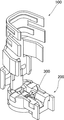
図1は、本発明の一実施形態にかかるL型同軸コネクタの組み立て前の状態での各部材を分離して示す図である。また、図2〜図4は、各構成部品の詳細を示す図である。本実施形態によるL型同軸コネクタは、同軸ケーブルの延出方向(中心軸)と相手コネクタとの嵌合方向とがほぼ垂直になっている。このL型同軸コネクタは、同軸ケーブル(図6〜図10参照)のシールド線と電気的に接続する外部導体100と、外部導体100に収容される絶縁座200と、絶縁座200に収容され、同軸ケーブルの中心導体と電気的に接続する端子300とによって構成されている。
FIG. 1 is a diagram showing each member in a state before assembly of an L-shaped coaxial connector according to an embodiment of the present invention. 2 to 4 are diagrams showing details of each component. In the L-shaped coaxial connector according to the present embodiment, the extending direction (center axis) of the coaxial cable and the fitting direction of the mating connector are substantially perpendicular. The L-shaped coaxial connector is housed in an
外部導体100は、りん青銅などの導電性材料の金属板を打ち抜き、折り曲げなどの加工をして作られる。図2に示すように、外部導体100は、略円筒状となるように丸められ、周方向の一箇所に間隙106を有する筒状部104と、間隙106をはさむ両側の位置から延出する相手コネクタ挿着方向(上下方向)に平行の2枚の保持腕108と、間隙106と直径方向で反対側に位置して、上記筒状部104の上端から起立して設けられた外蓋部112などから構成される。
The
筒状部104は、絶縁座200の本体部204を同心位置に収容する部分であり、絶縁座200の本体部204を受ける突状座部116を内面に有する。また、筒状部104の径方向外側の弾性を与えるための切込溝120が周方向に複数形成される。筒状部104における保持腕108の延出方向に垂直方向の両側の上部及び、保持腕108の各々の上部には、絶縁座200を圧入して固定するための係止部124a、124b、128a、128bが形成されている。また、筒状部104の外周面下端近傍には、相手コネクタとの嵌合時にロックの機能をもたらす環状ロック溝122が形成されている。
The
外蓋部112は、くびれた形状の屈曲部132と、屈曲部132につながって、屈曲時に筒状部104を覆う平蓋部136と、屈曲後に保持腕108を包囲して固定する固定部148と、同軸ケーブルのシールド線をカシメ包囲して電気的に接続するシールド線カシメ部156と、同軸ケーブルの外皮をカシメ包囲する外皮カシメ部168とを有する。外蓋部112は、同軸ケーブルと接続する際に筒状部104との接続部分である屈曲部132で屈曲し、同軸ケーブル上を覆う。
The
平蓋部136は、両端に屈曲時において下方に屈曲する側部140を有している。また、屈曲部132が屈曲する際に、内側となる面にエンボス加工により突状部144が形成されている。二つの側部140の内面同士の距離は、筒状部104の外径と同じか若しくはそれより大きい。
The
固定部148は、両端に屈曲時において下方に屈曲する側部152を持つ。屈曲部132が屈曲した後に、側部152は、保持腕108の外面に接し、さらに保持腕108の下方に回り込むように成形される。
The fixed
シールド線カシメ部156は、側部160を有し、屈曲部132が屈曲した後に、同軸ケーブルのシールド線をカシメ包囲して電気的に接続する。また、屈曲部132が屈曲する際に、内側となる面にエンボス加工により突状部164が形成され、同軸ケーブルが延伸方向に引っ張られても、同軸ケーブルがコネクタから抜けないようになっている。
The shield
外皮カシメ部168も、側部172を有し、屈曲部132が屈曲した後に、同軸ケーブルの外皮をカシメ包囲する。また、屈曲部132が屈曲する際に、内側となる面にエンボス加工により突状部176が形成され、同軸ケーブルが延伸方向に引っ張られても、同軸ケーブルがコネクタから抜けにくくなっている。
The
図3は絶縁座200の詳細構成を示し、(a)は斜視図、(b)は平面図である。絶縁座200は、絶縁材料をモールド成形して作られる。該絶縁材料として、例えば、リキッドクリスタルポリマー(LCP、液晶ポリマー)樹脂等にガラス繊維、炭素繊維やマイカ等のフィラーが充填された材料などの耐熱性があり柔軟性のある材料が用いられる。図3に示すように、絶縁座200は、略円筒状の本体部204と、本体部204の上部位置から半径外方の同軸ケーブルの延出方向に延びる肩部208と、肩部208と半径外方反対側に位置し、上方に延出する中蓋部212とを有している。絶縁座200の肩部208には、両側に案内壁248が傾斜して立設されているが、これは、中蓋部212が屈曲させられるときに、その案内をするものである。
3A and 3B show a detailed configuration of the insulating
絶縁座200の本体部204には、端子300の舌片状の嵌合部308を収容する略四角内筒面の端子収容部216が上下に貫通して形成され、本体部204の上部周縁には、フランジ部220が形成されている。また、フランジ部220において、肩部208の延出方向に垂直方向の両側には、半径外方に突出する突出部224a、224bが形成されている。また、肩部208上方の延出方向に垂直方向の両側にも外方に突出する突出部228a、228bが形成されている。絶縁座200を外部導体100に挿着することで、突出部224a、224b、228a、228bは、外部導体100の筒状部104及び保持腕108に作られた矩形の係止部124a、124bに圧入され、128a、128bに取り付けられる。
In the
中蓋部212は、本体部204と接続する部分において屈曲することができる。中蓋部212の長さは、中蓋部212が完全に屈曲した状態で、中蓋部212の先端が、肩部208の肩部端面252と延伸方向に関して同位置となる長さか若しくは、それよりも少し短い長さである。
The
肩部208の肩部端面252は、端子300のケーブル側端部302(図4参照)よりもケーブル延出方向外側に位置する。本体部204内側及び腕部内側には、本体部204の中蓋部212との接続位置から肩部端面252まで延びるように、ケーブル側から見て矩形に切り取られた溝形状を持つ。該矩形に切り取られた溝形状の側壁が前記案内壁248であり、底面である座部232の端子収容部側の一部には、端子300が配置される。また、座部232は、端子300のケーブル側端部302の外側に位置する、端子300が上面に配されない中心導体案内面236を有する。座部232は、ケーブル側縁部に、先端に向けて、端子の接触面の上面よりも下方に延びる斜面240を備える。さらに、該中心導体案内面236は、上方に盛り上がる隆起部244を有し、隆起部244の端部側は、上記斜面240の一部を形成する。
The
図4は端子300の詳細構成を示し、(a)は斜視図、(b)は(a)のC−C切断面における断面図である。端子300は、りん青銅などの導電性材料の金属板を打ち抜き、折り曲げ等の加工をして作られる。通常の場合、キャリアに複数の同一の端子が、一定の間隔で取り付けられていて、例えばケーブル側端部302がキャリアに接続した状態で、端子に折り曲げ加工等がなされる。端子300は、端子300のケーブル側端部302をキャリアから取り外した後に、L型同軸コネクタの組み立てに用いられる。図4に示すように、端子300は、同軸ケーブルの中心導体と接触して、電気的に接続される接触部304と、相手コネクタの端子と嵌合する嵌合部308を有している。さらに、端子300には、絶縁座200の端子係止部256a、256b、260a、260bに、それぞれ嵌合するための圧入部324a、324b、322a、322bを有している。
4A and 4B show a detailed configuration of the terminal 300, in which FIG. 4A is a perspective view and FIG. 4B is a cross-sectional view taken along the line CC of FIG. The terminal 300 is made by punching a metal plate made of a conductive material such as phosphor bronze and bending it. In a normal case, a plurality of identical terminals are attached to the carrier at regular intervals, and the terminal is bent or the like with the cable
接触部304は、同軸ケーブルの延出方向に延びている略平面形状であり、同軸ケーブルの中心導体と接触する上面には、中心導体と咬合して、同軸ケーブルが抜けないように、複数の凹部によって形成される凹凸部312が設けられている。また、該略平面の延出方向と逆側の中蓋側端部314近傍には、同軸ケーブル結線時に同軸ケーブルの中心導体の位置決めをし、同軸ケーブルの中心導体の先端位置を規制する突起部316が前後方向で同心位置よりもやや前方に設けられている。突起部316は、同軸ケーブルの中心導体の先端が奥の方へ行き過ぎるのを制限する中心導体規制面318を一辺(第1の辺)とする略三角形の平面形状を有し、前記第1の辺と対向する頂点が中蓋側端部314の近傍に位置する。中心導体の先端の外径が本体部の溝形状の側壁に当接する際に 該先端が当接する位置・大きさで前記一辺が設けられている突起部316は、接触部304の下側から打ち出されて形成される。また、突起部316は、中心導体規制面318から中蓋側端部314に向けて下がる傾斜を有し、中蓋側端部314近傍において最も低くなっている。そして、三角形の前記第1の辺と対向する頂点において、最も低くなっており、接触部304の平坦面と同じ高さになっている。また、突起部316の幅は、平面形状において、中心導体規制面318の幅が最も広く、中蓋側端部314近傍において最も狭くなっている。
The
例えば、中心導体の先端位置を規制する手段として、長方形の突起部を打ち出しにより形成した場合、圧入部324a、324bの部分の強度が劣化するおそれがある。しかし、本実施の形態では、圧入部324a、324bの近傍、すなわち中蓋側端部314の近傍において、打ち出しの幅及び高さが最小になっているので、この部分の強度が所定以上に維持される。したがって、本実施の形態による電気コネクタの突起部316は、このような形状を有することにより、同軸ケーブルの中心導体の先端の位置決めを行い、かつ、端子300の強度を保つことが可能になる。
For example, when a rectangular protrusion is formed by punching as a means for regulating the tip position of the center conductor, the strength of the press-
図4に示した突起部316は略三角形であるが、この形状に限定されず、類似の他の形状であっても、同様の効果を奏することができる。例えば、突起部316は、台形であってもよい。その場合、突起部316は、同軸ケーブル側の第1の辺(中心導体規制面318)を下底、中蓋側端部314側の第2の辺を上底とする台形となる。そして、前記第1の辺が中心導体の先端位置を規制する中心導体規制面318を形成し、前記第2の辺が圧入部324a、324bの近傍になる。また、突起部316は、卵形又は楕円形の一部を切り取ったような形状であってもよい。この場合、卵形又は楕円形の一部を切り取った部分が中心導体規制面318を形成し、中心導体規制面318の部分、または卵形又は楕円形の中心近傍の部分の幅がもっとも広くなる。
The
図4に示すように、嵌合部308は、接触部304の両端から下方に延長した二つの舌状片320a、320bを有している。舌状片320a、320bは、下方に行くに従って互いの距離を狭めるように傾斜しており、該距離の最も短い部分は、相手コネクタの端子(相手端子)の中心導体の大きさよりも小さい。また、舌状片320a、320bの先端は、相手端子の中心導体を中心側に案内できるように互いの距離を広げるように傾斜する。相手コネクタとの接続時には、相手コネクタの端子の中心導体の嵌合部が二つの舌状片320a、320bを押し広げることによって発生する舌状片320a、320bの内側方向への弾性力によって、相手端子の嵌合部が、把持される。本実施形態において、端子300は、雌型端子であるが、本発明においては、端子は、雄型端子であってもよい。また、舌状片は、2つに限られず、3つ以上であってもよい。
As shown in FIG. 4, the
図5は外部導体100、絶縁座200及び端子300の組み立て後の本発明の一実施形態のコネクタの図である。上記のコネクタは、以下に記載のように組み立てられる。まず、絶縁座200の本体部204を外部導体100の筒状部104に収容するように挿着することで、絶縁座200の突出部224a、224b、228a、228bを、外部導体100の係止部124a、124bに圧入し、係止部128a、128bに取り付ける。さらに、端子300の嵌合部308を、絶縁座の端子収容部216に収容するように圧入することで、端子300の圧入部322a、322b、324a、324bが、絶縁座200の端子係止部260a、260b、256a、256bに、それぞれ圧入する。それにより、端子300の接触部304の下面が、絶縁座200の座部232の上面に載置固定される。
FIG. 5 is a view of the connector according to an embodiment of the present invention after the
図6は同軸ケーブルをコネクタに配置した後の状態を示す図である。端子300の圧入固定後に、同軸ケーブルをコネクタに配置する。同軸ケーブルは、ストリッパ等を用いて、3段剥き加工されていて、同軸ケーブルの先端から中心導体C1、誘電体C2、シールド線C3及び外皮C4の順で露出している。同軸ケーブルの誘電体の断面を絶縁座200の肩部端面252に当接させ、中心導体C1が端子300に接触するように、同軸ケーブルの中心導体C1を端子300の接触部304及び絶縁座200の座部232の中心導体案内面236上に配置する。中心導体が剥き出しとなった部分が長すぎる場合には、中心導体C1の先端が、突起部316の中心導体規制面318に当接し、誘電体C2の断面が、肩部端面252に当接しないため、或いは中心導体C1が撓むので、組み立て作業者は、容易に組み立て異常を発見することができる。
FIG. 6 is a view showing a state after the coaxial cable is arranged in the connector. After the terminal 300 is press-fitted and fixed, the coaxial cable is placed in the connector. The coaxial cable is stripped in three stages using a stripper or the like, and is exposed from the tip of the coaxial cable in the order of the central conductor C1, the dielectric C2, the shield line C3, and the outer sheath C4. The central conductor C1 of the coaxial cable is connected to the
図7は、同軸ケーブルの中心導体C1を接触部304に載置した後に、外蓋部112を途中まで屈曲させた図である。外蓋部112を屈曲する際に、外蓋部112における平蓋部136の内面(主に、その内面の突状部144)からの押圧力を受けて、外蓋部112と共に中蓋部212が屈曲される。また、図8に、図7のA−A切断面における断面図を示す。図8に示されるように、同軸ケーブルの中心導体C1の誘電体等が剥がされて剥き出しとなった部分C11の下方には、端子300の接触部304及び絶縁座200の座部232の中心導体案内面236がある。一方で、同軸ケーブルの誘電体C2、シールド線C3及び外皮C4は、絶縁座200のケーブル延伸方向外側に位置している。
FIG. 7 is a view in which the
さらに、外部導体100の外蓋部112(特に、平蓋部136)が筒状部104を覆うように倒される際に、その屈曲部を屈曲させる。その際に、外部導体100における平蓋部136によって、絶縁座200の中蓋部212の外面に押圧力が印加される。そして、中蓋部212は、該押圧力を受けて、中蓋部212の内面(すなわち、押圧面)と端子300を接触部304の上面(すなわち、中心導体C1を支持するための支持面)との間で同軸ケーブルの中心導体C1を挟圧する。その後、固定部148によって、保持腕108を包囲して、外蓋部112が開かないように外蓋部112の位置を固定する。さらに、シールド線カシメ部156によってシールド線C3をカシメ包囲して、シールド線C3と外部導体100の電気的接続を確保する。また、外皮カシメ部168によって外皮C4をカシメ包囲して、同軸ケーブルがコネクタから外れないように固定する。上記のように、中心導体C1は、挟圧され、シールド線C3及び外皮C4は、カシメ包囲されて大きく変形するが、シールド線から露出している誘電体C2は、大きく挟圧されることもカシメ包囲されることもなく、同軸ケーブルがコネクタに固定された状態であっても大きく変形することがない。従って、コネクタ接続時のケーブルのインピーダンス等の電気的特性の変化が少ない。
Further, when the outer lid portion 112 (particularly, the flat lid portion 136) of the
図9に固定後のコネクタ及び同軸ケーブルの図を、図10に、図9のB−B切断面における断面図を示す。中蓋部212の内面(押圧面)と端子300の接触部304の上面(支持面)によって、中心導体C1を挟圧し、端子300と中心導体C1の電気的接続を確保する。接触部304の上面にある凹凸部312が、中心導体C1に咬合するため、端子300から中心導体C1が離れにくく、中心導体の電気的接続が安定的に保たれる。さらに、中蓋部212の内面と絶縁座200の隆起部244による挟圧力によって、中心導体C1を保持する。中心導体C1は、中蓋部212の内面と端子300の接触部304の上面による挟圧力によって、電気的接続が確保され、中蓋部212の内面と隆起部244による挟圧力によって保持されるため、半田付けによって中心導体C1を端子に固定する必要がない。また、同軸ケーブル延伸方向に張力が同軸ケーブルに印加された場合、中蓋部212と隆起部244との間の中心導体C1の一部分に該張力がかかるが、中蓋部212は平面で、隆起部244は滑らかな曲面で形成されており、通常尖っていないため、中心導体が断線しにくい。一方で、中蓋部212と隆起部244によって、中心導体C1が挟圧されていないと、中心導体の、中蓋部と端子の接触部のケーブル側端部との間にある部分に張力がかかる。この場合には、接触部のケーブル側の先端角部は尖っていることが多く、中心導体の該先端角部に接触する部分近辺に張力が集中するため、断線の原因となり易い。さらに、接触部のケーブル側の端部が、端子の使用前にキャリアと接続していた部分である場合には、端部に棘等が残って、中心導体が傷つくことがあるため、特に断線し易くなる。
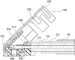
FIG. 9 is a view of the connector and the coaxial cable after being fixed, and FIG. 10 is a cross-sectional view taken along the line BB in FIG. The center conductor C1 is clamped by the inner surface (pressing surface) of the
図8及び図10に示すように、誘電体C2を絶縁座200の外側に位置するように同軸ケーブルを配置すると、誘電体C2に覆われた部分C12の下方に空間ができる。このとき、外蓋部112が誘電体C2を下方に押して移動させることができるため、中蓋部212の厚みを、誘電体C2の厚みよりも薄くして、低背化をすることができる。部分C12の中心線が、部分C11の中心線よりも下方に移動しても、絶縁座200は、ケーブル側端部に斜面240を備えるため、中心導体C1は、絶縁座の肩部端面252で折れ曲がることなく、斜面240に沿って滑らかに下方へ曲がり、断線しにくい。また、誘電体C2が、上部から外蓋部112によって押圧されても、座部232によって挟圧されず、変形しないため、コネクタ接続時のケーブルのインピーダンス等の電気的特性の変化が少ない。
As shown in FIGS. 8 and 10, when the coaxial cable is arranged so that the dielectric C2 is positioned outside the insulating
また、屈曲時に中蓋部212の先端部を肩部端面252と延伸方向に一致させることによって、絶縁座200及び肩部端面252に断面が当接する誘電体C2によって、中心導体C1と外部導体100との間の空間が隔てられることになるため、中心導体C1が外部導体100に接触短絡しにくくすることができる。
In addition, the center conductor C1 and the
同軸ケーブルのシールド線C3に覆われ、外皮に覆われない部分C13は、シールド線カシメ部156によってカシメられることにより、シールド線C3が誘電体C2内部に押し込まれる。そのため、本実施形態において、部分C13における中心の位置は、部分C12における中心と高さ方向において同一の位置にあるが、本発明では、下方に移動してもよい。
A portion C13 covered by the shielded wire C3 of the coaxial cable and not covered by the outer cover is crimped by the shielded
本実施形態において、外皮C4の一部は、外皮カシメ部168によってカシメられることにより圧縮して薄くなるが、一定の厚さを持つため、外皮に覆われる部分C14内の中心導体は、下方に移動するが、本発明では、部分C14が同一の高さを保ってもよい。
In this embodiment, a part of the outer skin C4 is compressed and thinned by being caulked by the outer
図11は、端子300が絶縁座200に挿着され、端子300の圧入部322a、322b、324a、324bが、絶縁座200の端子係止部260a、260b、256a、256bにそれぞれ嵌合して固定された状態の絶縁座200を示す図である。絶縁座200の中蓋部212は、外部導体100の外蓋部112を屈曲する際に、外蓋部112における平蓋部136からの押圧力を中蓋部212の外面で受けて、中蓋部212は、肩部208の両側にある傾斜して立設された案内壁248と中蓋部212の側面両側にある先端側面262により、中心導体C1を正しく固定するための位置(すなわち、正規位置)に屈曲して倒れるように案内される。そして、中蓋部212の先端側面262は、それぞれ案内壁248に接するか、わずかな隙間を有して対面し、中蓋部凹面264も、座部凸面266に接するか、わずかな隙間を有して対面して、中蓋部212の内面と端子300の接触部304との間で同軸ケーブルの中心導体C1を挟圧する。
In FIG. 11, the terminal 300 is inserted into the insulating
絶縁座200を成形するための材料として、耐熱性があり柔軟性のある材料、例えば、リキッドクリスタルポリマー(LCP、液晶ポリマー)樹脂等にガラス繊維、炭素繊維やマイカ等のフィラーが充填された成形材料が使用される。
As a material for forming the insulating
絶縁座200が、フィラーが配合されたLCP樹脂等で成形された場合に、中蓋部212の根元におけるフィラーの分布が偏っていたり、該根元の屈曲位置にちょうどフィラーが存在したりする場合等によって、中蓋部212が根元部分の適切な位置で屈曲しないことが生じる。そのような場合、中蓋部212の押圧面が、端子300の接触部304の支持面に対して正確に重なる位置からずれることになり、十分な押圧力によって、正規位置で同軸ケーブルの中心導体C1を挟圧することができず、その結果として、同軸ケーブルの特性インピーダンスが悪化し、高周波特性が不安定となる問題が生じる場合がある。
When the insulating
中蓋部212が、その根元部分の適切な位置から屈曲され、中蓋部212の押当面が、常に正規位置で中心導体C1を接触部304に支持面に挟圧できるようにするために、図11に示すように、中蓋部212の根元部分に、中蓋部212の厚さが最薄になる切込部270を設けている。切込部270は、中蓋部212の根元部分に位置し、中蓋部212の幅方向に延びる、V字形またはU字形等の折り曲げ容易な形状の溝(すなわち、ノッチ)である。
In order to allow the
外蓋部112からの押圧力を受けて、接触部304側に倒れる際に、折り曲げられ易い形状の切込部270の位置で折り曲がるため、中心導体C1を十分に挟圧して固定できる正規位置に、中蓋部212を屈曲して倒すことができる。切込部270は、中蓋部212を屈曲して、中蓋部212の押圧面と接触部304の支持面との間で、中心導体C1を狭圧したときに、少なくもと一部が切断される場合がある。切込部の一部又は全部が切断された場合であっても、中蓋部212は、外蓋部112(特に、平蓋部136)から受ける十分な押圧力で固定されており、さらに、中蓋部凹面264と座部凸面266、先端側面262と案内壁248によって、中蓋部212は支持されて固定される。
A normal position where the center conductor C1 can be sufficiently clamped and fixed because it is bent at the position of the notched
以上、本発明者によってなされた発明をその実施の形態に基づき具体的に説明したが、本発明は前記実施の形態に限定されるものではなく、その要旨を逸脱しない範囲で種々変更可能であることはいうまでもない。 As mentioned above, the invention made by the present inventor has been specifically described based on the embodiment. However, the invention is not limited to the embodiment, and various modifications can be made without departing from the scope of the invention. Needless to say.
L型同軸コネクタのような電気コネクタには、様々な用途があり、例えば、情報通信機器産業及び自動車産業など幅広い産業分野において、情報機器や電気機器の内部配線等に利用することができる。 An electrical connector such as an L-shaped coaxial connector has various uses. For example, it can be used for internal wiring of information equipment and electrical equipment in a wide range of industrial fields such as the information communication equipment industry and the automobile industry.
100 外部導体
104 筒状部
106 間隙
108 保持腕
112 外蓋部
116 突状座部
120 切込溝
122 環状ロック溝
124a、124b 係止部
128a、128b 係止部
132 屈曲部
136 平蓋部
140 側部
144 突状部
148 固定部
152 側部
156 シールド線カシメ部
160 側部
164 突状部
168 外皮カシメ部
176 突状部
200 絶縁座
204 本体部
208 肩部
212 中蓋部
216 端子収容部
220 フランジ部
224a、224b 突出部
228a、228b 突出部
232 座部
236 中心導体案内面
240 斜面
244 隆起部
248 案内壁
252 肩部端面
256a、256b 端子係止部
260a、260b 端子係止部
262 先端側面
264 中蓋部凹面
266 座部凸面
270、270a、270b、270c 切込部
300 端子
302 ケーブル側端部
304 接触部
308 嵌合部
312 凹凸部
314 中蓋側端部
316 突起部
318 中心導体規制面
320a、320b 舌状片
322a、322b 圧入部
324a、324b 圧入部
C1 中心導体
C2 誘電体
C3 シールド線
C4 外皮
100
Claims (7)
前記外部導体の前記筒状部に収容される絶縁性材料の絶縁座と、
前記絶縁座の端子収容部に収容され、前記同軸ケーブルの中心導体と電気接続される導電性材料の端子とを有し、
前記端子は、
前記同軸ケーブルの中心導体と上面で接触する平板状の接触部と、
相手コネクタとの嵌合時に前記相手コネクタの端子と弾性接触する嵌合部と、
前記接触部の前記同軸ケーブルと反対側の端部の近傍に設けられ、前記絶縁座の前記端子収容部の溝に圧入される圧入部と、
前記接触部の上面に設けられ、前記同軸ケーブルの中心導体の先端位置を規制する突起部と、を含み、
前記突起部は、前記接触部の下側から打ち出されて形成され、
前記突起部の幅は、前記同軸ケーブル側が前記端部よりも広いことを特徴とする電気コネクタ。 It has a cylindrical portion that opens in the fitting direction with the mating connector, supports the coaxial cable so that the central axis of the coaxial cable is substantially perpendicular to the fitting direction, and is electrically connected to the shielded wire of the coaxial cable. An outer conductor of conductive material to be
An insulating seat made of an insulating material accommodated in the cylindrical portion of the outer conductor;
A terminal of a conductive material that is accommodated in a terminal accommodating portion of the insulating seat and electrically connected to a central conductor of the coaxial cable;
The terminal is
A flat contact portion in contact with the central conductor of the coaxial cable on the upper surface;
A fitting portion that elastically contacts the terminal of the mating connector when mated with the mating connector;
A press-fit portion provided in the vicinity of the end of the contact portion opposite to the coaxial cable, and press-fitted into the groove of the terminal accommodating portion of the insulating seat;
A protrusion that is provided on the upper surface of the contact portion and regulates a tip position of a center conductor of the coaxial cable;
The protruding portion is formed by being punched from the lower side of the contact portion,
The electrical connector according to claim 1, wherein a width of the protruding portion is wider on the coaxial cable side than the end portion.
Priority Applications (4)
| Application Number | Priority Date | Filing Date | Title |
|---|---|---|---|
| JP2012095605A JP5615319B2 (en) | 2012-04-19 | 2012-04-19 | Electrical connector |
| TW102109217A TWI517504B (en) | 2012-04-19 | 2013-03-15 | Electrical connector |
| CN201310134190.1A CN103378436B (en) | 2012-04-19 | 2013-04-17 | Electrical connector |
| KR1020130042083A KR101675620B1 (en) | 2012-04-19 | 2013-04-17 | Electrical connector |
Applications Claiming Priority (1)
| Application Number | Priority Date | Filing Date | Title |
|---|---|---|---|
| JP2012095605A JP5615319B2 (en) | 2012-04-19 | 2012-04-19 | Electrical connector |
Publications (3)
| Publication Number | Publication Date |
|---|---|
| JP2013222685A JP2013222685A (en) | 2013-10-28 |
| JP2013222685A5 JP2013222685A5 (en) | 2014-05-08 |
| JP5615319B2 true JP5615319B2 (en) | 2014-10-29 |
Family
ID=49463216
Family Applications (1)
| Application Number | Title | Priority Date | Filing Date |
|---|---|---|---|
| JP2012095605A Active JP5615319B2 (en) | 2012-04-19 | 2012-04-19 | Electrical connector |
Country Status (4)
| Country | Link |
|---|---|
| JP (1) | JP5615319B2 (en) |
| KR (1) | KR101675620B1 (en) |
| CN (1) | CN103378436B (en) |
| TW (1) | TWI517504B (en) |
Families Citing this family (13)
| Publication number | Priority date | Publication date | Assignee | Title |
|---|---|---|---|---|
| JP5949804B2 (en) * | 2014-02-21 | 2016-07-13 | 第一精工株式会社 | Electrical connector and electrical connector manufacturing method |
| JP5943017B2 (en) * | 2014-02-21 | 2016-06-29 | 第一精工株式会社 | Electrical connector and electrical connector manufacturing method |
| JP6379403B2 (en) * | 2014-12-02 | 2018-08-29 | ヒロセ電機株式会社 | Coaxial cable connector with core wire holding and fixing function |
| JP6446725B2 (en) * | 2014-12-02 | 2019-01-09 | ヒロセ電機株式会社 | Coaxial cable connector with improved crimp strength and impedance performance |
| JP6601289B2 (en) | 2016-03-23 | 2019-11-06 | 株式会社オートネットワーク技術研究所 | Terminal fitting |
| JP6330851B2 (en) | 2016-05-25 | 2018-05-30 | 第一精工株式会社 | Connector assembly and electrical connector |
| JP6447596B2 (en) | 2016-09-08 | 2019-01-09 | 第一精工株式会社 | Electrical connector |
| JP6443637B2 (en) * | 2016-10-06 | 2018-12-26 | 第一精工株式会社 | Coaxial cable connector and coaxial cable connection method |
| JP6443636B2 (en) * | 2016-10-06 | 2018-12-26 | 第一精工株式会社 | Coaxial cable connector and coaxial cable connection method |
| JP6791499B2 (en) * | 2016-11-24 | 2020-11-25 | 日本圧着端子製造株式会社 | Pressure welding connection type contacts and coaxial connectors |
| CN108695623A (en) * | 2018-05-15 | 2018-10-23 | 启东乾朔电子有限公司 | Cable coaxial connector |
| CN112448203A (en) | 2019-08-30 | 2021-03-05 | 爱沛股份有限公司 | Electrical connector and method of manufacturing an electrical connector |
| JP7313990B2 (en) * | 2019-09-09 | 2023-07-25 | 日本航空電子工業株式会社 | Connector and connection method |
Family Cites Families (11)
| Publication number | Priority date | Publication date | Assignee | Title |
|---|---|---|---|---|
| JPH04112476A (en) * | 1990-08-31 | 1992-04-14 | Noritz Corp | Ceramic heater |
| JP3154214B2 (en) * | 1992-09-25 | 2001-04-09 | ソニー株式会社 | headphone |
| JP3119199B2 (en) * | 1997-05-16 | 2000-12-18 | 日本電気株式会社 | Remote video monitoring device |
| US6217374B1 (en) * | 1999-11-18 | 2001-04-17 | Molex Incorporated | Electrical connector with wire management system |
| JP3656187B2 (en) * | 2000-04-17 | 2005-06-08 | 日本航空電子工業株式会社 | Connector for shielded cable |
| US7066774B2 (en) * | 2004-06-30 | 2006-06-27 | Emerson Electric Co. | Electrical connector and sleeve apparatus and method of assembly |
| JP3119199U (en) * | 2005-12-02 | 2006-02-16 | 佳必▼其▲國際股▼ふん▲有限公司 | Coaxial connector |
| US7485000B2 (en) * | 2006-10-20 | 2009-02-03 | Jiangsu Famfull Electronics Co., Ltd. | Coaxial electrical connector |
| JP4321873B2 (en) | 2006-12-13 | 2009-08-26 | ヒロセ電機株式会社 | Coaxial electrical connector |
| JP3160403U (en) * | 2010-04-09 | 2010-06-24 | 光紅建聖股▲分▼有限公司 | Coaxial cable connector |
| JP2013525994A (en) * | 2010-05-07 | 2013-06-20 | シンセン エレクトリカル コネクター テクノロジー リミテッド | Flex type coaxial electrical connector |
-
2012
- 2012-04-19 JP JP2012095605A patent/JP5615319B2/en active Active
-
2013
- 2013-03-15 TW TW102109217A patent/TWI517504B/en active
- 2013-04-17 CN CN201310134190.1A patent/CN103378436B/en active Active
- 2013-04-17 KR KR1020130042083A patent/KR101675620B1/en active IP Right Grant
Also Published As
| Publication number | Publication date |
|---|---|
| TW201401692A (en) | 2014-01-01 |
| KR101675620B1 (en) | 2016-11-11 |
| JP2013222685A (en) | 2013-10-28 |
| TWI517504B (en) | 2016-01-11 |
| CN103378436A (en) | 2013-10-30 |
| KR20130118259A (en) | 2013-10-29 |
| CN103378436B (en) | 2017-04-26 |
Similar Documents
| Publication | Publication Date | Title |
|---|---|---|
| JP5615319B2 (en) | Electrical connector | |
| JP5763007B2 (en) | Electrical connector | |
| KR101110148B1 (en) | Insulation displacement contact and electric connector using the same | |
| JP4241488B2 (en) | Connector for coaxial cable | |
| US20120135621A1 (en) | Floating connector | |
| JP2019185858A (en) | Connector with l-shaped coaxial terminal and its manufacturing method | |
| JP5615318B2 (en) | Electrical connector | |
| US7261597B2 (en) | Electrical connector with low profile | |
| JP5867872B2 (en) | Coaxial connector for board | |
| US20060258219A1 (en) | Electrical connector | |
| JP2015015175A (en) | Coaxial cable connector | |
| KR102535074B1 (en) | Connector and connector system | |
| CN108110438B (en) | Electric connector and combination thereof | |
| CN113285314B (en) | Line terminal connecting terminal and coaxial cable connector | |
| CN216450830U (en) | Wire clamping connector assembly | |
| KR102338051B1 (en) | Coaxial Connectors and Coaxial Connectors with Coaxial Cables | |
| WO2006087953A1 (en) | Coaxial connector and communication device | |
| KR101922566B1 (en) | Electrical connector and electrical connector assembly | |
| JP2015015176A (en) | Coaxial cable connector | |
| JP2013109831A (en) | Coaxial low profile connector |
Legal Events
| Date | Code | Title | Description |
|---|---|---|---|
| A521 | Request for written amendment filed |
Free format text: JAPANESE INTERMEDIATE CODE: A523 Effective date: 20140325 |
|
| A621 | Written request for application examination |
Free format text: JAPANESE INTERMEDIATE CODE: A621 Effective date: 20140325 |
|
| A977 | Report on retrieval |
Free format text: JAPANESE INTERMEDIATE CODE: A971007 Effective date: 20140827 |
|
| TRDD | Decision of grant or rejection written | ||
| A01 | Written decision to grant a patent or to grant a registration (utility model) |
Free format text: JAPANESE INTERMEDIATE CODE: A01 Effective date: 20140903 |
|
| A61 | First payment of annual fees (during grant procedure) |
Free format text: JAPANESE INTERMEDIATE CODE: A61 Effective date: 20140909 |
|
| R150 | Certificate of patent or registration of utility model |
Ref document number: 5615319 Country of ref document: JP Free format text: JAPANESE INTERMEDIATE CODE: R150 |
|
| R250 | Receipt of annual fees |
Free format text: JAPANESE INTERMEDIATE CODE: R250 |
|
| R250 | Receipt of annual fees |
Free format text: JAPANESE INTERMEDIATE CODE: R250 |
|
| R250 | Receipt of annual fees |
Free format text: JAPANESE INTERMEDIATE CODE: R250 |
|
| R250 | Receipt of annual fees |
Free format text: JAPANESE INTERMEDIATE CODE: R250 |
|
| S531 | Written request for registration of change of domicile |
Free format text: JAPANESE INTERMEDIATE CODE: R313531 |
|
| R350 | Written notification of registration of transfer |
Free format text: JAPANESE INTERMEDIATE CODE: R350 |
|
| R250 | Receipt of annual fees |
Free format text: JAPANESE INTERMEDIATE CODE: R250 |
|
| R250 | Receipt of annual fees |
Free format text: JAPANESE INTERMEDIATE CODE: R250 |
|
| R250 | Receipt of annual fees |
Free format text: JAPANESE INTERMEDIATE CODE: R250 |