JP5615063B2 - Passenger conveyor stop device - Google Patents
Passenger conveyor stop device Download PDFInfo
- Publication number
- JP5615063B2 JP5615063B2 JP2010151731A JP2010151731A JP5615063B2 JP 5615063 B2 JP5615063 B2 JP 5615063B2 JP 2010151731 A JP2010151731 A JP 2010151731A JP 2010151731 A JP2010151731 A JP 2010151731A JP 5615063 B2 JP5615063 B2 JP 5615063B2
- Authority
- JP
- Japan
- Prior art keywords
- motor
- ratchet
- rotation
- handrail
- ratchet wheel
- Prior art date
- Legal status (The legal status is an assumption and is not a legal conclusion. Google has not performed a legal analysis and makes no representation as to the accuracy of the status listed.)
- Active
Links
Images


Description
この発明は、踏段の異常下降を抑制する乗客コンベヤの停止装置に関する。 The present invention relates to a passenger conveyor stop device that suppresses abnormal lowering of steps.
従来、モータと、モータの駆動により循環移動する踏段と、踏段と係合可能な踏段係合部材と、踏段係合部材を変位させる係合部材変位装置と、モータの回転軸と連動して回転するラチェットホイールと、ラチェットホイールに係合可能なラチェット係合部材と、踏段が停止しているときにモータの回動軸を制動するモータ制動装置とを備えたエスカレータの停止装置が知られている。踏段係合部材は、踏段と係合可能な係合可能位置と、係合可能位置から後退した係合解除位置との間で変位する。また、踏段係合部材は、踏段の循環移動が停止するときに、係合解除位置から係合可能位置へ変位する。踏段が停止しているときに、例えば、規定値を超える重量の人等が踏段に乗ることにより、モータ制動装置の制動力を超える力がモータの回転軸に加えられる。これにより、踏段が下降して係合可能部材が踏段と係合する。ラチェット係合部材は、係合可能部材が踏段と係合することにより、ラチェットホイールと係合して、踏段の異常下降が抑制される(例えば、特許文献1参照)。 Conventionally, a motor, a step that circulates by driving of the motor, a step engagement member that can be engaged with the step, an engagement member displacement device that displaces the step engagement member, and a rotation shaft of the motor. An escalator stop device comprising a ratchet wheel that engages, a ratchet engagement member that can be engaged with the ratchet wheel, and a motor braking device that brakes the rotating shaft of the motor when the step is stopped is known. . The step engaging member is displaced between an engageable position that can be engaged with the step and an engagement release position that is retracted from the engageable position. Further, the step engaging member is displaced from the disengaged position to the engageable position when the circulating movement of the step is stopped. When the step is stopped, for example, when a person having a weight exceeding a specified value gets on the step, a force exceeding the braking force of the motor braking device is applied to the rotating shaft of the motor. Thereby, the step is lowered and the engageable member is engaged with the step. The ratchet engaging member is engaged with the ratchet wheel when the engageable member is engaged with the step, so that the abnormal lowering of the step is suppressed (for example, see Patent Document 1).
しかしながら、踏段と係合可能な踏段係合部材と、踏段係合部材を係合解除位置から係合可能位置へと変位させる係合部材変位装置とが必要であり、乗客コンベヤの停止装置の構造が複雑であるという問題点があった。 However, a step engaging member that can be engaged with the step and an engaging member displacing device that displaces the step engaging member from the disengaged position to the engageable position are required. There was a problem that is complicated.
この発明は、踏段の異常下降を抑制するとともに、構造を簡単にすることができる乗客コンベヤの停止装置を提供するものである。 The present invention provides a stop device for a passenger conveyor that can suppress an abnormal descent of a step and simplify the structure.
この発明に係る乗客コンベヤの停止装置は、モータと、前記モータの駆動により循環移動する踏段と、前記モータの駆動により前記踏段と連動して循環移動する手摺と、前記モータの駆動を制御する制御装置とを備えた乗客コンベヤに用いられる乗客コンベヤの停止装置であって、前記モータの回転軸の回転を検出する回転検出装置と、前記モータの前記回転軸と連動して回転するラチェットホイールと、前記ラチェットホイールに係合可能な係合可能位置と前記ラチェットホイールとの係合が解除される係合解除位置との間で変位可能に設けられ、前記ラチェットホイールと係合することにより前記ラチェットホイールの回転を停止させるラチェット係合部材と、前記制御装置の制御により前記モータの駆動が停止しているときに、前記回転検出装置が前記モータの回転軸の回転を検出することにより、前記ラチェット係合部材を前記係合解除位置から前記係合可能位置に変位させるラチェット係合部材変位装置と、前記手摺の循環移動を検出する手摺移動検出装置とを備え、前記ラチェット係合部材変位装置は、前記モータの駆動が停止しているときに、前記回転検出装置が前記モータの回転軸の回転を検出し、さらに、前記手摺移動検出装置が前記手摺の循環移動を検出することにより、前記ラチェット係合部材を前記係合解除位置から前記係合可能位置に変位させる。 The passenger conveyor stop device according to the present invention includes a motor, a step that circulates by driving the motor, a handrail that circulates in conjunction with the step by driving the motor, and a control that controls driving of the motor. A passenger conveyor stop device used in a passenger conveyor equipped with a device, a rotation detection device for detecting rotation of a rotation shaft of the motor, a ratchet wheel that rotates in conjunction with the rotation shaft of the motor, The ratchet wheel is provided so as to be displaceable between an engageable position where the ratchet wheel can be engaged and an engagement release position where the engagement with the ratchet wheel is released, and by engaging with the ratchet wheel. A ratchet engaging member that stops the rotation of the motor, and when the drive of the motor is stopped by the control of the control device, By detecting device detects the rotation of the rotary shaft of the motor, a ratchet engagement member displacement device to displace the ratchet engaging member to the engageable position from the engagement releasing position, the circulating movement of the handrail The ratchet engagement member displacement device detects the rotation of the rotation shaft of the motor when the driving of the motor is stopped, When the handrail movement detecting device detects the circulation movement of the handrail, the ratchet engaging member is displaced from the disengaged position to the engageable position .
この発明に係る乗客コンベヤの停止装置によれば、ラチェット係合部材変位装置は、モータの駆動が停止しているときに、回転検出装置がモータの回転軸の回転を検出することにより、ラチェット係合部材を係合解除位置から係合可能位置に変位させるので、踏段の異常下降を抑制することができ、また、踏段と係合する踏段係合部材や、踏段係合部材を係合可能位置へと変位させる係合部材変位装置を不要とすることができる。これにより、踏段の異常下降を抑制するとともに、乗客コンベヤの停止装置の構造を簡単にすることができる。 According to the passenger conveyor stopping device of the present invention, the ratchet engaging member displacing device detects the rotation of the rotation shaft of the motor when the drive of the motor is stopped. Since the combined member is displaced from the disengaged position to the engageable position, abnormal lowering of the step can be suppressed, and the step engaging member that engages with the step or the position where the step engaging member can be engaged. It is possible to eliminate the need for an engaging member displacing device that displaces the heel. Thereby, while suppressing the abnormal fall of a step, the structure of the stop apparatus of a passenger conveyor can be simplified.
実施の形態1.
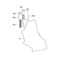
図1はこの発明の実施の形態1に係るエスカレータを示す側断面図である。図において、建物の上階床と下階床との間には、主枠1が掛け渡されている。主枠1は、上階側水平部1aと、下階側水平部1bと、上階側水平部1aと下階側水平部1bとの間に位置する傾斜部1cとを有している。上階側水平部1aおよび下階側水平部1bのそれぞれには、機械室が設けられている。
1 is a side sectional view showing an escalator according to
主枠1には、一対の欄干2が主枠1の長手方向に延びて設けられている。また、主枠1には、複数の踏段3が上階側水平部1aおよび下階側水平部1bの間を循環移動可能に設けられている。また、主枠1には、手摺案内レール(図示せず)が主枠1の長手方向に延びて設けられている。手摺案内レールには、移動手摺4が循環移動可能に設けられている。
The
上階側水平部1aの機械室には、モータ5と、モータ5の駆動を制御する制御装置6と、モータ5の駆動により発生する回転力が伝達される減速機7と、モータ5の回転軸の回転を検出する回転検出装置8とが設けられている。回転検出装置8は、減速機7の回転軸の回転を検出することにより、モータ5の回転軸の回転を検出する。
In the machine room of the upper floor side
また、上階側水平部1aの機械室には、駆動チェーン9を介して減速機7の回転力が伝達される駆動スプロケット10と、上部スプロケット11と、手摺駆動用スプロケット12と、ラチェットホイール13とが設けられている。上部スプロケット11、手摺駆動用スプロケット12およびラチェットホイール13は、駆動スプロケット10と同軸上に配置されており、駆動スプロケット10と同期して回転するようになっている。
Further, in the machine room of the upper floor side
下階側水平部1bの機械室には、下部スプロケット14が設けられている。上部スプロケット11と下部スプロケット14とには、互いに隣り合う踏段3を連結する無端状の踏段チェーン15が巻き掛けられている。これにより、踏段3は、モータ5の駆動により循環移動する。
A
手摺駆動用スプロケット12は、手摺駆動用チェーン16を介して移動手摺4を駆動させる手摺駆動装置17に接続されている。これにより、移動手摺4は、モータ5の駆動により踏段3の循環移動に連動して循環移動する。主枠1には、移動手摺4の循環移動を検出する手摺移動検出装置18が設けられている。
The
また、上階側水平部1aの機械室には、ラチェットホイール13に係合可能なラチェット係合部材19と、ラチェット係合部材19を変位させるラチェット係合部材変位装置20とが設けられている。
Further, a
モータ5には、モータ5の駆動が停止しているときに、モータ5の回転軸を制動するモータ制動装置(図示せず)が設けられている。モータ5の回転軸は、モータ5の駆動が停止しているときに、モータ制動装置により回転が防止される。 The motor 5 is provided with a motor braking device (not shown) that brakes the rotating shaft of the motor 5 when the driving of the motor 5 is stopped. The rotation shaft of the motor 5 is prevented from rotating by the motor braking device when the driving of the motor 5 is stopped.
モータ5の駆動が停止しているときに踏段3の異常下降を抑制する停止装置(乗客コンベヤの停止装置)21は、回転検出装置8と、ラチェットホイール13と、手摺移動検出装置18と、ラチェット係合部材19と、ラチェット係合部材変位装置20とを有している。
A stop device (passenger conveyor stop device) 21 that suppresses abnormal lowering of the step 3 when the drive of the motor 5 is stopped includes a
図2は図1のラチェットホイール13とラチェット係合部材19とラチェット係合部材変位装置20とを示す正面図である。ラチェット係合部材19は、主枠1(図1)に対して固定された回動軸19aと、回動軸19aに回動可能に保持された磁性体の回動部19bと、回動部19bに設けられたばね製の伸縮部19cとを有している。伸縮部19cは、回動部19bの反回動軸19a側の部分に配置されている。ラチェット係合部材19は、ラチェットホイール13と係合可能となる係合可能位置と、係合可能位置から回動軸19aを中心に回動してラチェットホイール13との係合が解除される係合解除位置との間で変位する。伸縮部19cの伸縮量は、踏段3を緊急停止する際に求められる制動距離の量と同一とする。
FIG. 2 is a front view showing the
ラチェット係合部材変位装置20は、圧縮ばね部20aと、コイル部20bとを有している。圧縮ばね部20aは、ラチェット係合部材19の位置が係合解除位置となるようにラチェット係合部材19を付勢する。コイル部20bは、制御装置6により通電されることにより磁力を発生して、圧縮ばね部20aの付勢力に逆らってラチェット係合部材19を係合可能位置へ変位させる。つまり、ラチェット係合部材変位装置20は、コイル部20bが通電されることによりラチェット係合部材19を係合可能位置へ変位させ、また、コイル部20bが非通電とされることによりラチェット係合部材19を係合解除位置へ変位させる。
The ratchet engagement
図3は図1の制御装置6と停止装置21との間の信号の流れを示すブロック図である。制御装置6は、制御装置本体6aと、アンド素子6bとを有している。回転検出装置8および手摺移動検出装置18の信号は、アンド素子6bに送られる。アンド素子6bは、回転検出装置8および手摺移動検出装置18の両方からの信号を受けることにより、制御装置本体6aへ信号を送る。制御装置6は、制御装置本体6aがアンド素子6bから信号を受けることにより、ラチェット係合部材変位装置20を駆動させる。つまり、制御装置6は、回転検出装置8がモータ5の回動軸の回転を検出し、さらに、手摺移動検出装置18が移動手摺4の循環移動を検出することにより、ラチェット係合部材変位装置20を駆動させる。
FIG. 3 is a block diagram showing a signal flow between the
また、ラチェット係合部材変位装置20は、ラチェット係合部材変位装置20が駆動するときにエスカレータの安全回路を遮断する。安全回路には、スカートガード安全スイッチ、インレットガードスイッチおよび踏段チェーン安全装置等が接続されている。ラチェット係合部材変位装置20が安全回路を遮断することにより、スカートガード安全スイッチ、インレットガードスイッチおよび踏段チェーン安全装置の自動復帰が防止される。なお、エスカレータの安全回路の遮断は、ラチェット係合部材変位装置20に限らず、例えば、制御装置6が行ってもよい。
Further, the ratchet engagement
次に停止装置21の動作について説明する。モータ5の回転軸は、制御装置6の制御により停止する。これにより、踏段3の循環移動と、移動手摺4の循環移動が停止される。また、モータ5の駆動が停止されているときには、モータ制動装置により、モータ5の回転軸の回転が防止される。このとき、例えば、規定値を超える重量の人等が踏段3に乗ることにより、モータ制動装置の制動力を超える力がモータ5の回転軸に加えられた場合には、踏段3の異常下降が発生し、モータ5の回転軸が回転する。移動手摺4は、踏段3の異常下降に連動して異常下降する。
Next, the operation of the
その後、回転検出装置8は、モータ5の回転軸の回転を検出して、アンド素子6bへ信号を送る。手摺移動検出装置18は、移動手摺4の循環移動を検出して、アンド素子6bへ信号を送る。アンド素子6bは、回転検出装置8および手摺移動検出装置18の両方からの信号を受けることにより、制御装置本体6aへ信号を送る。
Thereafter, the
その後、制御装置6は、ラチェット係合部材変位装置20のコイル部20bを通電して、ラチェット係合部材19を係合可能位置に変位させる。これにより、ラチェット係合部材19がラチェットホイール13と係合する。その結果、踏段3の異常下降が抑制される。このとき、ラチェット係合部材19は、伸縮部19cがラチェットホイール13に押圧されて収縮しながら、ラチェットホイール13を制動する。
Thereafter, the
ラチェット係合部材19とラチェットホイール13との係合を解除する場合には、制御装置6がラチェット係合部材変位装置20のコイル部20bを非通電とする。これにより、コイル部20bの磁力が消されて、ラチェット係合部材19は、圧縮ばね部20aの付勢力により、係合可能位置から係合解除位置に変位する。
When the engagement between the
以上説明したように、この発明の実施の形態1に係るエスカレータの停止装置21によれば、ラチェット係合部材変位装置20は、モータ5の駆動が停止しているときに、回転検出装置8がモータ5の回転軸の回転を検出することにより、ラチェット係合部材19を係合解除位置から係合可能位置に変位させるので、踏段3の異常下降を抑制することができる。また、踏段3と係合する踏段係合部材や、踏段係合部材を係合可能位置へと変位させる係合部材変位装置を不要とすることができ、エスカレータの停止装置21の構造を簡単にすることができる。
As described above, according to the
また、ラチェット係合部材変位装置20は、モータ5の駆動が停止しているときに、回転検出装置8がモータ5の回転軸の回転を検出し、さらに、手摺移動検出装置18が移動手摺4の循環移動を検出することにより、ラチェット係合部材19を係合解除位置から係合可能位置に変位させるので、回転検出装置8および手摺移動検出装置18の何れか一方が誤検出した場合であっても、停止装置21の誤作動の発生を防ぐことができる。
In the ratchet engagement
また、ラチェット係合部材19は、ラチェット係合部材19がラチェットホイール13と係合するときに、ラチェットホイール13に押圧されて収縮しながらラチェットホイール13の回転を停止させるので、ラチェット係合部材19がラチェットホイール13と係合するときに、踏段3が急停止することを防止することができる。
Further, when the
なお、上記実施の形態1では、乗客コンベヤの停止装置として、エスカレータの停止装置21を例に説明したが、踏段の踏板が水平面から傾斜して配置された動く歩道の停止装置であってもよい。
In the first embodiment, the
また、上記実施の形態1では、回転検出装置8がモータ5の回転軸の回転を検出し、さらに、手摺移動検出装置18が移動手摺4の循環移動を検出することにより、ラチェット係合部材19が係合解除位置から係合可能位置に変位する構成について説明したが、回転検出装置8がモータ5の回転軸の回転を検出し、または、手摺移動検出装置18が移動手摺4の循環移動を検出することにより、ラチェット係合部材19が係合解除位置から係合可能位置に変位する構成であってもよい。
In the first embodiment, the
また、上記実施の形態1では、コイル部20bを通電することによりラチェット係合部材19を係合可能位置に変位させ、また、コイル部20bを非通電とすることによりラチェット係合部材19を係合解除位置に変位させる構成について説明したが、コイル部20bを通電することによりラチェット係合部材19を係合解除位置に変位させ、また、コイル部20bを非通電とすることによりラチェット係合部材19を係合可能位置に変位させる構成であってもよい。
In the first embodiment, the
また、上記実施の形態1では、コイル部20bが通電され、磁力が発生することにより駆動するラチェット係合部材変位装置20について説明したが、磁力に限らず、その他の動力を用いて駆動するラチェット係合部材変位装置20であってもよい。
In the first embodiment, the ratchet engagement
1 主枠、1a 上階側水平部、1b 下階側水平部、1c 傾斜部、2 欄干、3 踏段、4 移動手摺、5 モータ、6 制御装置、6a 制御装置本体、6b アンド素子、7 減速機、8 回転検出装置、9 駆動チェーン、10 駆動スプロケット、11 上部スプロケット、12 手摺駆動用スプロケット、13 ラチェットホイール、14 下部スプロケット、15 踏段チェーン、16 手摺駆動用チェーン、17 手摺駆動装置、18 手摺移動検出装置、19 ラチェット係合部材、19a 回動軸、19b 回動部、19c 伸縮部、20 ラチェット係合部材変位装置、20a 圧縮ばね部、20b コイル部、21 停止装置(乗客コンベヤの停止装置)。
DESCRIPTION OF
Claims (2)
前記モータの回転軸の回転を検出する回転検出装置と、
前記モータの前記回転軸と連動して回転するラチェットホイールと、
前記ラチェットホイールに係合可能な係合可能位置と前記ラチェットホイールとの係合が解除される係合解除位置との間で変位可能に設けられ、前記ラチェットホイールと係合することにより前記ラチェットホイールの回転を停止させるラチェット係合部材と、
前記モータの駆動が停止しているときに、前記回転検出装置が前記モータの回転軸の回転を検出することにより、前記ラチェット係合部材を前記係合解除位置から前記係合可能位置に変位させるラチェット係合部材変位装置と、
前記手摺の循環移動を検出する手摺移動検出装置と
を備え、
前記ラチェット係合部材変位装置は、前記モータの駆動が停止しているときに、前記回転検出装置が前記モータの回転軸の回転を検出し、さらに、前記手摺移動検出装置が前記手摺の循環移動を検出することにより、前記ラチェット係合部材を前記係合解除位置から前記係合可能位置に変位させることを特徴とする乗客コンベヤの停止装置。 Passengers used in passenger conveyors comprising a motor, a step that circulates by driving the motor, a handrail that circulates in conjunction with the step by driving the motor, and a control device that controls the driving of the motor A conveyor stop device,
A rotation detection device for detecting rotation of a rotation shaft of the motor;
A ratchet wheel that rotates in conjunction with the rotating shaft of the motor;
The ratchet wheel is provided so as to be displaceable between an engageable position where the ratchet wheel can be engaged and an engagement release position where the engagement with the ratchet wheel is released, and by engaging with the ratchet wheel. A ratchet engaging member for stopping rotation of the
When the drive of the motor is stopped, the rotation detection device detects the rotation of the rotation shaft of the motor, thereby displacing the ratchet engagement member from the disengagement position to the engageable position. Ratchet engagement member displacement device ;
A handrail movement detection device for detecting the circular movement of the handrail ,
In the ratchet engagement member displacement device, when the driving of the motor is stopped, the rotation detection device detects the rotation of the rotation shaft of the motor, and the handrail movement detection device further circulates the handrail. By detecting this, the ratchet engaging member is displaced from the disengaged position to the engageable position .
Priority Applications (1)
| Application Number | Priority Date | Filing Date | Title |
|---|---|---|---|
| JP2010151731A JP5615063B2 (en) | 2010-07-02 | 2010-07-02 | Passenger conveyor stop device |
Applications Claiming Priority (1)
| Application Number | Priority Date | Filing Date | Title |
|---|---|---|---|
| JP2010151731A JP5615063B2 (en) | 2010-07-02 | 2010-07-02 | Passenger conveyor stop device |
Publications (3)
| Publication Number | Publication Date |
|---|---|
| JP2012012187A JP2012012187A (en) | 2012-01-19 |
| JP2012012187A5 JP2012012187A5 (en) | 2013-01-17 |
| JP5615063B2 true JP5615063B2 (en) | 2014-10-29 |
Family
ID=45599081
Family Applications (1)
| Application Number | Title | Priority Date | Filing Date |
|---|---|---|---|
| JP2010151731A Active JP5615063B2 (en) | 2010-07-02 | 2010-07-02 | Passenger conveyor stop device |
Country Status (1)
| Country | Link |
|---|---|
| JP (1) | JP5615063B2 (en) |
Families Citing this family (2)
| Publication number | Priority date | Publication date | Assignee | Title |
|---|---|---|---|---|
| PL2872436T3 (en) * | 2012-07-13 | 2016-11-30 | Safety brake for an escalator or a moving walkway | |
| CN106458528B (en) * | 2014-06-26 | 2019-06-07 | 三菱电机株式会社 | The safety device of passenger conveyors |
Family Cites Families (6)
| Publication number | Priority date | Publication date | Assignee | Title |
|---|---|---|---|---|
| JPS51160391U (en) * | 1975-06-14 | 1976-12-20 | ||
| JPS63160990A (en) * | 1986-12-24 | 1988-07-04 | 株式会社日立ビルシステムサービス | Passenger conveyor |
| JP3497316B2 (en) * | 1996-01-17 | 2004-02-16 | 三菱電機株式会社 | Man conveyor |
| JPH101277A (en) * | 1996-06-14 | 1998-01-06 | Hitachi Ltd | Moving handrail speed abnormality detecting device of passenger conveyer |
| JP2005343625A (en) * | 2004-06-02 | 2005-12-15 | Mitsubishi Electric Corp | Emergency stop device for passenger conveyor |
| JP2008001470A (en) * | 2006-06-22 | 2008-01-10 | Toshiba Elevator Co Ltd | Auxiliary brake device for passenger conveyor |
-
2010
- 2010-07-02 JP JP2010151731A patent/JP5615063B2/en active Active
Also Published As
| Publication number | Publication date |
|---|---|
| JP2012012187A (en) | 2012-01-19 |
Similar Documents
| Publication | Publication Date | Title |
|---|---|---|
| RU2660167C2 (en) | Stopping system for cab of boarding bridges for accessing aircraft and ships | |
| US9663327B2 (en) | Elevator braking system | |
| CN109665420A (en) | A kind of drag device with safety tongs | |
| JP4817203B2 (en) | Auxiliary brake device for passenger conveyor | |
| CN108290713B (en) | Elevator device | |
| US20100018809A1 (en) | Elevator arrangement, method and safety structure | |
| AU2016231645B2 (en) | Braking system for a hoisted structure and method of controlling braking a hoisted structure | |
| TWI644846B (en) | Escalator | |
| JP2010018419A (en) | Passenger conveyer | |
| JP4672656B2 (en) | Elevator safety device | |
| JP5615063B2 (en) | Passenger conveyor stop device | |
| JP6272507B2 (en) | Elevator equipment | |
| JP5809755B2 (en) | Elevator emergency stop device and elevator | |
| EP3328772B1 (en) | Safety block for elevator | |
| JP4292215B2 (en) | Elevator governor device | |
| JP2011168369A (en) | Escalator | |
| KR20170113868A (en) | Safety brake control apparatus for emergency stop of escalator | |
| JP2006327811A (en) | Moving handrail speed detection device of passenger conveyor | |
| KR101190236B1 (en) | Speed regulator for elevator | |
| JP4937038B2 (en) | Passenger conveyor stop device | |
| JP2011190067A (en) | Step for preventing fall caused by fixing failure | |
| JP2013129524A (en) | Safety device for passenger conveyor | |
| KR100789485B1 (en) | Escalator for safety | |
| US20070089937A1 (en) | Emergency brake device for elevator | |
| JP2010247943A (en) | Passenger conveyor device |
Legal Events
| Date | Code | Title | Description |
|---|---|---|---|
| A521 | Request for written amendment filed |
Free format text: JAPANESE INTERMEDIATE CODE: A523 Effective date: 20121126 |
|
| A621 | Written request for application examination |
Free format text: JAPANESE INTERMEDIATE CODE: A621 Effective date: 20121126 |
|
| A977 | Report on retrieval |
Free format text: JAPANESE INTERMEDIATE CODE: A971007 Effective date: 20140109 |
|
| A131 | Notification of reasons for refusal |
Free format text: JAPANESE INTERMEDIATE CODE: A131 Effective date: 20140114 |
|
| A521 | Request for written amendment filed |
Free format text: JAPANESE INTERMEDIATE CODE: A523 Effective date: 20140224 |
|
| TRDD | Decision of grant or rejection written | ||
| A01 | Written decision to grant a patent or to grant a registration (utility model) |
Free format text: JAPANESE INTERMEDIATE CODE: A01 Effective date: 20140902 |
|
| A61 | First payment of annual fees (during grant procedure) |
Free format text: JAPANESE INTERMEDIATE CODE: A61 Effective date: 20140909 |
|
| R150 | Certificate of patent or registration of utility model |
Ref document number: 5615063 Country of ref document: JP Free format text: JAPANESE INTERMEDIATE CODE: R150 |
|
| R250 | Receipt of annual fees |
Free format text: JAPANESE INTERMEDIATE CODE: R250 |
|
| R250 | Receipt of annual fees |
Free format text: JAPANESE INTERMEDIATE CODE: R250 |
|
| S533 | Written request for registration of change of name |
Free format text: JAPANESE INTERMEDIATE CODE: R313533 |
|
| R350 | Written notification of registration of transfer |
Free format text: JAPANESE INTERMEDIATE CODE: R350 |