JP5604612B1 - Bushing for lead acid battery and lead acid battery - Google Patents
Bushing for lead acid battery and lead acid battery Download PDFInfo
- Publication number
- JP5604612B1 JP5604612B1 JP2014513837A JP2014513837A JP5604612B1 JP 5604612 B1 JP5604612 B1 JP 5604612B1 JP 2014513837 A JP2014513837 A JP 2014513837A JP 2014513837 A JP2014513837 A JP 2014513837A JP 5604612 B1 JP5604612 B1 JP 5604612B1
- Authority
- JP
- Japan
- Prior art keywords
- bushing
- lead
- acid battery
- annular protrusion
- lid
- Prior art date
- Legal status (The legal status is an assumption and is not a legal conclusion. Google has not performed a legal analysis and makes no representation as to the accuracy of the status listed.)
- Active
Links
Images


Classifications
-
- H—ELECTRICITY
- H01—ELECTRIC ELEMENTS
- H01M—PROCESSES OR MEANS, e.g. BATTERIES, FOR THE DIRECT CONVERSION OF CHEMICAL ENERGY INTO ELECTRICAL ENERGY
- H01M10/00—Secondary cells; Manufacture thereof
- H01M10/06—Lead-acid accumulators
- H01M10/12—Construction or manufacture
-
- H—ELECTRICITY
- H01—ELECTRIC ELEMENTS
- H01M—PROCESSES OR MEANS, e.g. BATTERIES, FOR THE DIRECT CONVERSION OF CHEMICAL ENERGY INTO ELECTRICAL ENERGY
- H01M50/00—Constructional details or processes of manufacture of the non-active parts of electrochemical cells other than fuel cells, e.g. hybrid cells
- H01M50/50—Current conducting connections for cells or batteries
- H01M50/531—Electrode connections inside a battery casing
- H01M50/54—Connection of several leads or tabs of plate-like electrode stacks, e.g. electrode pole straps or bridges
- H01M50/541—Connection of several leads or tabs of plate-like electrode stacks, e.g. electrode pole straps or bridges for lead-acid accumulators
-
- H—ELECTRICITY
- H01—ELECTRIC ELEMENTS
- H01M—PROCESSES OR MEANS, e.g. BATTERIES, FOR THE DIRECT CONVERSION OF CHEMICAL ENERGY INTO ELECTRICAL ENERGY
- H01M50/00—Constructional details or processes of manufacture of the non-active parts of electrochemical cells other than fuel cells, e.g. hybrid cells
- H01M50/10—Primary casings, jackets or wrappings of a single cell or a single battery
- H01M50/147—Lids or covers
- H01M50/155—Lids or covers characterised by the material
- H01M50/157—Inorganic material
- H01M50/159—Metals
-
- H—ELECTRICITY
- H01—ELECTRIC ELEMENTS
- H01M—PROCESSES OR MEANS, e.g. BATTERIES, FOR THE DIRECT CONVERSION OF CHEMICAL ENERGY INTO ELECTRICAL ENERGY
- H01M50/00—Constructional details or processes of manufacture of the non-active parts of electrochemical cells other than fuel cells, e.g. hybrid cells
- H01M50/10—Primary casings, jackets or wrappings of a single cell or a single battery
- H01M50/172—Arrangements of electric connectors penetrating the casing
- H01M50/174—Arrangements of electric connectors penetrating the casing adapted for the shape of the cells
- H01M50/176—Arrangements of electric connectors penetrating the casing adapted for the shape of the cells for prismatic or rectangular cells
-
- H—ELECTRICITY
- H01—ELECTRIC ELEMENTS
- H01M—PROCESSES OR MEANS, e.g. BATTERIES, FOR THE DIRECT CONVERSION OF CHEMICAL ENERGY INTO ELECTRICAL ENERGY
- H01M50/00—Constructional details or processes of manufacture of the non-active parts of electrochemical cells other than fuel cells, e.g. hybrid cells
- H01M50/50—Current conducting connections for cells or batteries
- H01M50/543—Terminals
- H01M50/552—Terminals characterised by their shape
- H01M50/561—Hollow metallic terminals, e.g. terminal bushings
-
- Y—GENERAL TAGGING OF NEW TECHNOLOGICAL DEVELOPMENTS; GENERAL TAGGING OF CROSS-SECTIONAL TECHNOLOGIES SPANNING OVER SEVERAL SECTIONS OF THE IPC; TECHNICAL SUBJECTS COVERED BY FORMER USPC CROSS-REFERENCE ART COLLECTIONS [XRACs] AND DIGESTS
- Y02—TECHNOLOGIES OR APPLICATIONS FOR MITIGATION OR ADAPTATION AGAINST CLIMATE CHANGE
- Y02E—REDUCTION OF GREENHOUSE GAS [GHG] EMISSIONS, RELATED TO ENERGY GENERATION, TRANSMISSION OR DISTRIBUTION
- Y02E60/00—Enabling technologies; Technologies with a potential or indirect contribution to GHG emissions mitigation
- Y02E60/10—Energy storage using batteries
-
- Y—GENERAL TAGGING OF NEW TECHNOLOGICAL DEVELOPMENTS; GENERAL TAGGING OF CROSS-SECTIONAL TECHNOLOGIES SPANNING OVER SEVERAL SECTIONS OF THE IPC; TECHNICAL SUBJECTS COVERED BY FORMER USPC CROSS-REFERENCE ART COLLECTIONS [XRACs] AND DIGESTS
- Y02—TECHNOLOGIES OR APPLICATIONS FOR MITIGATION OR ADAPTATION AGAINST CLIMATE CHANGE
- Y02P—CLIMATE CHANGE MITIGATION TECHNOLOGIES IN THE PRODUCTION OR PROCESSING OF GOODS
- Y02P70/00—Climate change mitigation technologies in the production process for final industrial or consumer products
- Y02P70/50—Manufacturing or production processes characterised by the final manufactured product
Landscapes
- Chemical & Material Sciences (AREA)
- Chemical Kinetics & Catalysis (AREA)
- Electrochemistry (AREA)
- General Chemical & Material Sciences (AREA)
- Engineering & Computer Science (AREA)
- Manufacturing & Machinery (AREA)
- Inorganic Chemistry (AREA)
- Sealing Battery Cases Or Jackets (AREA)
- Connection Of Batteries Or Terminals (AREA)
Abstract
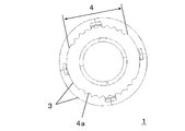
本発明に係る鉛蓄電池用ブッシングは、樹脂性の蓋にインサート成型される鉛蓄電池用のブッシング1であって、ブッシング1は、中空の円筒状をなしており、ブッシング1の外周面には、複数段の環状突起3が形成されており、複数段の環状突起3の全周の一部に、切込4aが連なる連続切込部4が形成されており、切込4aは、環状突起3の上面、側面、下面の全てが削られた、平面視で略V字形状をなしている。 The lead-acid battery bushing according to the present invention is a lead-acid battery bushing 1 that is insert-molded into a resinous lid, and the bushing 1 has a hollow cylindrical shape. A plurality of annular projections 3 are formed, and a continuous cut portion 4 is formed on a part of the entire circumference of the plurality of annular projections 3, and the cuts 4 a are continuous. All of the upper surface, the side surface, and the lower surface of the substrate are cut off to form a substantially V shape in plan view.
Description
本発明は、鉛蓄電池用ブッシングと、これを用いた鉛蓄電池に関する。 The present invention relates to a lead-acid battery bushing and a lead-acid battery using the same.
自動車用などの鉛蓄電池において、正極板と負極板とをセパレータを介して交互に対峙させた極板群は、電槽の内部を仕切板で区切って設けたセル室に各々収納されている。隣り合うセル室の異なる極性どうしは接続部材で接続され、両端のセル室の一方の極性には鉛合金製の極柱が接続されている。電槽の開口部を塞ぐ蓋には、インサート成型された鉛合金製のブッシングが設けられ、極性は、その一端がブッシング内に挿入されて、溶接などで一体化されて、鉛蓄電池の端子を構成している。 In a lead storage battery for automobiles or the like, electrode plate groups in which a positive electrode plate and a negative electrode plate are alternately opposed to each other via a separator are housed in cell chambers provided by partitioning the inside of the battery case with a partition plate. Different polarities of adjacent cell chambers are connected by a connecting member, and a pole column made of a lead alloy is connected to one polarity of the cell chambers at both ends. The lid that closes the opening of the battery case is provided with an insert-molded lead alloy bushing, and the polarity is inserted into the bushing and integrated by welding, etc. It is composed.
樹脂製の蓋と鉛合金製のブッシングとは、インサート成型されていても接着力は生じていないので、僅かながら隙間が生じることになる。この隙間を電解液が這い上がることで、端子が腐食することが課題となっている。 Since the resin lid and the lead alloy bushing are insert-molded, no adhesive force is generated, so that a slight gap is generated. The problem is that the terminal corrodes due to the electrolytic solution creeping up through the gap.
一方、端子は、自動車からの動力線と接続される際、自動車メーカーでは、一定の範囲でトルク管理され、自動車に組付けされる。しかしながら、一般ユーザー等では、トルク管理されずに、高いトルク値で締め付けられる機会がある。この場合、端子が、締め付けに対する耐性が高くないと、メンテナンスなどで締め付けを繰り返した際に、ブッシングの破損やブッシングと蓋との気密性が確保できなくなる。 On the other hand, when the terminal is connected to the power line from the automobile, the automobile manufacturer manages the torque within a certain range and attaches the terminal to the automobile. However, general users have an opportunity to tighten with a high torque value without torque management. In this case, if the terminal is not highly resistant to tightening, the bushing may be damaged or the airtightness between the bushing and the lid cannot be ensured when the tightening is repeated for maintenance.
特許文献1には、ブッシングの外周面に環状突起を設け、この環状突起の下面に、周方向に沿って、複数の凹部を設ける技術が記載されている。これにより、ブッシングと、蓋の樹脂材料との接触面積が増加することによって、電槽とブッシングとの応力が低減するため、電解液の這い上がりが抑制できる。また、蓋の樹脂材料が、凹部に食い込むことによって、締め付けに対する耐性が向上する。
しかしながら、近年、充電制御車等の普及により、端子に電流センサー等が接続され、締め付けトルクがさらに増加する機会が増えた。このような場合だと、特許文献1に記載された技術を採用しても、電解液の這い上がりを抑制することも、締め付けに対する耐性を向上させることも困難になっている。
However, in recent years, with the spread of charge control vehicles and the like, current sensors and the like are connected to the terminals, and the opportunity for further increasing the tightening torque has increased. In such a case, even if the technique described in
本発明は、このような課題を解決するためのものであって、締め付けトルクがさらに増加する場合においても、電解液の這い上がりが抑制され、締め付けに対する耐性も高い鉛蓄電池用ブッシングを提供することを目的とする。 The present invention is for solving such problems, and provides a bushing for a lead storage battery in which the creeping of the electrolytic solution is suppressed and the resistance to tightening is high even when the tightening torque further increases. With the goal.
本発明に係る鉛蓄電池用ブッシングは、樹脂性の蓋にインサート成型される鉛蓄電池用のブッシングであって、ブッシングは、中空の円筒状をなしており、ブッシングの外周面には、複数段の環状突起が形成されており、複数段の環状突起のうち、最上段を除く環状突起の全周の一部に、切込が連なる連続切込部が形成されており、切込は、環状突起の上面、側面、下面の全てが削られた、平面視で略V字形状をなしていることを特徴とする。 A lead-acid battery bushing according to the present invention is a lead-acid battery bushing that is insert-molded into a resinous lid. The bushing has a hollow cylindrical shape, and a plurality of steps are provided on the outer peripheral surface of the bushing. An annular protrusion is formed, and a continuous cut portion is formed in a part of the entire circumference of the annular protrusion excluding the uppermost step among the plurality of annular protrusions. All of the upper surface, the side surface, and the lower surface of the substrate are cut off and have a substantially V shape in plan view.
本発明を用いれば、電解液の這い上がりが抑制され、締め付けに対する耐性も高い鉛蓄電池用ブッシングを提供することができる。 If this invention is used, the creeping of electrolyte solution will be suppressed and the bushing for lead storage batteries with the high tolerance with respect to clamping can be provided.
以下、本発明の実施形態を図面に基づいて詳細に説明する。なお、本発明は、以下の実施形態に限定されるものではない。また、本発明の効果を奏する範囲を逸脱しない範囲で、適宜変更は可能である。 Hereinafter, embodiments of the present invention will be described in detail with reference to the drawings. In addition, this invention is not limited to the following embodiment. Moreover, it can change suitably in the range which does not deviate from the range which has the effect of this invention.
図1は、本発明の一実施形態における鉛蓄電池用ブッシング1の構成を示した外観図である。本実施形態における鉛蓄電池用ブッシング1は、樹脂性の蓋にインサート成型されるブッシングである。 FIG. 1 is an external view showing the configuration of a lead-acid battery bushing 1 according to an embodiment of the present invention. The lead-acid battery bushing 1 in this embodiment is a bushing that is insert-molded into a resinous lid.
図1に示すように、ブッシング1は、中空の円筒状をなしており、内側に極柱の先端を挿入する穴を有する主部2と、外周面に形成された複数段の環状突起3とを有する。そして、複数段環状突起3の全周の一部には、切込4aが連なる連続切込部4が形成されており、切込4aは、環状突起3の上面、側面、下面の全てが削られた、平面視で略V字形状をなしている。
As shown in FIG. 1, the
このように、切込4aを、環状突起3の上面、側面、下面の全てが削られた、平面視で略V字形状に形成することによって、ブッシング1と蓋(樹脂材料)との接触面積が増大し、これにより、締め付け時のトルクを分散するとともに、アンカー効果により接着力を高めることができる。
In this way, the contact area between the
また、切込4aを、環状突起3の全周に設けるのではなく、全周の一部に設けることによって、電解液が這い上がる時の距離を長くでき、これにより、電解液の這い上がりを抑制することができる。
In addition, by providing the
さらに、連続切込部4を、複数段の環状突起3のうち、最上段を除く環状突起3に形成することによって、ブッシング1を蓋にインサート成型する際の安定性を向上させることができる。
Furthermore, the stability at the time of insert-molding the
図2は、本発明の他の実施形態における鉛蓄電池用ブッシング1の構成を示した下面図である。 FIG. 2 is a bottom view showing the configuration of a lead-acid battery bushing 1 according to another embodiment of the present invention.
図2に示すように、連続切込部4は、環状突起3の周方向において、互いに、中心軸に対して対称な位置に形成されている。このように、連続切込部4を、中心軸に対して対称な位置に形成することによって、ブッシング1がバランスの良い構造体になるため、ブッシング1を鋳造する際の安定性を向上させることができる。
As shown in FIG. 2, the
なお、図2では、2つの連続切込部4を、環状突起3の周方向において、互いに、中心軸に対して対称な位置に形成した例を示したが、これに限定されず、連続切込部4を、環状突起3の周方向において、複数個、均等に分散して形成しても、同様の効果を得ることができる。例えば、3つの連続切込部4を、環状突起3の周方向において、互いに、中心軸に対して、120度ずつ離れた位置に形成してもよい。
2 shows an example in which the two
図3は、本発明の他に実施形態における鉛蓄電池用ブッシング1の構成を示した外観図である。 FIG. 3 is an external view showing the configuration of the lead-acid battery bushing 1 in the embodiment in addition to the present invention.
図3に示すように、環状突起3の各段に形成された連続切込部4は、それぞれ、周方向にずれた位置に形成されている。換言すれば、各連続切込部4は、軸方向(上下方向)で同一位置とならないように形成されている。連続切込部4を、このような配置にすることにより、運送時などにおいて、鉛蓄電池を上下に積載する際に、端子に加わる軸方向の荷重に対しても、十分に耐えることができるようになる。
As shown in FIG. 3, the
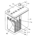
図4は、本発明におけるブッシンブ1を備えた鉛蓄電池の構成を示した概略図である。
FIG. 4 is a schematic view showing a configuration of a lead storage battery including the
図4に示すように、鉛蓄電池は、仕切板6aで区切られた複数のセル室6bを有する電槽6と、各セル室6b内に収容された電極群5と、ブッシング1の環状突起3が樹脂材料の中に埋まるようにインサート成型された樹脂性の蓋8とを備えている。ここで、電極群5は、正極板5aと負極板5bとをセパレータ5cを介して交互に対峙されている。また、隣り合うセル室6bの異なる極性どうしは、接続部材7aで接続されている。両端のセル室6bの一方の極性に接続した極柱7bは、その一端がブッシング1の中空部に挿入されて、ブッシング1と一体化された端子9を構成している。電解液は、蓋8に設けた液口(図示せず)から注入され、液口は液口栓10で塞がれている。
As shown in FIG. 4, the lead storage battery includes a
ブッシング1、接続部材7aおよび極柱7bは、例えば、Pb−SnやPb−Sbなどの鉛合金からなる。電槽6および蓋8は、例えば、ポリプロピレンなどの樹脂材料からなる。電槽6に設けるセル室6bの数は、鉛蓄電池の公称電圧(直列数、2Vの倍数)によって決まる。極柱7bの先端をブッシング1の内側に挿入した後の一体化は、例えば、溶接によって行う。
The
以下、実施例によって、本発明の効果を説明する。 Hereinafter, the effects of the present invention will be described with reference to examples.
(ブッシングA)
図1に示すように、最上段(5段目)以外の環状突起3の全周のうち一部に、環状突起3の上面、側面、下面の全てを削った略V字型の切込4aが連なる連続切込部4を設けたブッシングを作製した。ここで、ブッシングは、Pb−Sb合金(Pb:Sb=0.974:0.026)を用いた。(Bushing A)
As shown in FIG. 1, a substantially V-shaped
(ブッシングB)
ブッシングAに対して、最上段の環状突起3にも、他の段と同様の連続切込部4を設けたこと以外は、ブッシングAと同様のブッシングを作製した。(Bushing B)
For the bushing A, a bushing similar to the bushing A was prepared except that the uppermost
(ブッシングC)
ブッシングBに対して、環状突起3の全周に連続切込部4を設けたこと以外は、ブッシングBと同様のブッシングを作製した。(Bushing C)
A bushing similar to the bushing B was produced except that the
(ブッシングD)
ブッシングAに対して、図2に示すように、環状突起3の周方向における略対称の位置に、2つの連続切込部4を設けたこと以外は、ブッシングAと同様のブッシングを作製した。(Bushing D)
As shown in FIG. 2, a bushing similar to the bushing A was produced except that the two
(ブッシングE)
ブッシングDに対して、図3に示すように、環状突起の各段に形成された連続切込部4を、それぞれ、周方向にずれた位置に形成したこと以外は、ブッシングDと同様のブッシングを作製した。(Bushing E)
As shown in FIG. 3, the bushing D is the same as the bushing D except that the
(ブッシングF)
ブッシングA〜Eと同じ材質で、特許文献1に記載された、環状突起の下面に、周方向に沿って、複数の矩形状の凹部を設けたブッシングを作製した。(Bushing F)
A bushing made of the same material as the bushings A to E and provided with a plurality of rectangular recesses along the circumferential direction on the lower surface of the annular protrusion described in
(鉛蓄電池A)
図4に示すように、鉛化合物を鉛合金製の格子に塗布してなる正極板5aおよび負極板5bを、ポリエチレン製のセパレータ5cを介して交互に対峙させて積層し、極板群5を作製した。この極板群5を、ポリプロピレン製の電槽6を仕切板6aで区切って設けた6つのセル室6bに収納し、隣り合うセル室6bの異なる極性どうしをPb−Sb製の接続部材7aで接続し、両端のセル室6bの一方の極性を、Pb−Sb製の極柱7bに接続した。(Lead battery A)
As shown in FIG. 4, a
上記のブッシングAを、環状突起3が樹脂材料(ポリプロピレン製)の中に埋まるように、インサート成型にて蓋8を作製した。なお、本実施例では、インサート成型の安定性の差異を際立たせるため、通常よりも高い圧入力でインサート成型を行った。そして電槽6の開口部を蓋8で閉じて接合した後、ブッシングAの主部2の穴に極柱7bの先端を挿入して溶接し、端子9を作製した。さらに、蓋8に設けた液口から電解液である希硫酸を適量注入し、液口を液口栓10で塞いだ後、所定条件の充放電を行うことで、12V、52Ah(5時間率容量)の鉛蓄電池Aを作製した。
The
(鉛蓄電池B〜F)
鉛蓄電池Aに対して、ブッシングAに代えてブッシングB、C、D、EおよびFを用いたこと以外は、鉛蓄電池Aと同様の鉛蓄電池B、C、D、EおよびFを作製した。(Lead batteries B to F)
For lead acid battery A, lead acid batteries B, C, D, E and F were produced in the same manner as lead acid battery A, except that bushings B, C, D, E and F were used instead of bushing A.
上述した鉛蓄電池A〜Fに対して、下記の評価を行った。 The following evaluation was performed with respect to the lead storage batteries A to F described above.
(耐締め付けトルク値),
正極端子にアダプタをはめ、これにトルクレンチを用いて時計回り方向に回転させて、耐締め付けトルク値を測定した。(Tightening torque value),
An adapter was fitted to the positive electrode terminal, and this was rotated clockwise using a torque wrench to measure the anti-tightening torque value.
(電解液の這い上がり)
インサート成型後24時間以上経過した蓋8を、1.24g/mLの硫酸にブッシング1の環状突起3の最下段が下方まで浸るように電解液を注入し、25℃下で2週間放置した後、端子9を解体してブッシング1の表面を観察し、環状突起3の何段目まで腐食によって黒色化したかを評価した。この段数が小さいものほど、電解液の這い上がりが抑えられていることになる。(Soiling electrolyte)
After the
(インサート成型の安定性)
一体成型された蓋8を分解してブッシング1を取り出し、蓋8とブッシング1との境界部の表面を観察した。ブッシング1の表面に蓋8の材料となる樹脂の被覆(以下、樹脂被り)がなければ、インサート成型の安定性は高いと判断できる。(Stability of insert molding)
The integrally molded
表1に、その評価結果を示す。 Table 1 shows the evaluation results.

表1に示すように、切込4aを、環状突起3の上面、側面、下面の全てを削った略V字型としたブッシングCを用いた鉛蓄電池Cは、特許文献1に記載されたブッシングFを用いた鉛蓄電池Fと比べて、耐締め付けトルク値が向上している。これは、蓋8(樹脂材料)とブッシングとの接触面積が増大することで、締め付け時のトルクを分散するとともにアンカー効果が大きくなったためだと考えられる。
As shown in Table 1, the lead-acid battery C using the bushing C in which the
また、連続切込部4を、環状突起3の全周の一部に設けたブッシングBを用いた鉛蓄電池Bは、連続切込部4を環状突起3の全周に設けたブッシングCを用いた鉛蓄電池Cと比べて、電解液の這い上がりが抑制されている。これは、連続切込部4を必要最小限とすることで、電解液が這い上がる時の距離を長くできたからだと考えられる。
Further, the lead-acid battery B using the bushing B in which the
また、連続切込部4を、複数段の環状突起3のうち最上段には設けないようにしたブッシングAを用いた鉛蓄電池Aは、最上段の環状突起3にも他の段と同様の連続切込部4を設けたブッシングBを用いた鉛蓄電池Bと比べて、ブッシングを蓋8にインサート成型する際の安定性が大きくなっている。特許文献1とは異なり、切込4aがV字型である場合、最上段の環状突起3にも連続切込部4を設けると、インサート成型時に樹脂がブッシング1の表面に流れ出やすくなり、樹脂被りが発生しやすくなる。連続切込部4を複数段の環状突起3のうち最上段に設けなくても十分な耐締め付けトルク値を示すことからも、ブッシングBよりもブッシングAの形態の方が好ましいことがわかる。
Further, the lead storage battery A using the bushing A in which the
また、環状突起3の周方向における略対象の位置に複数の連続切込部4を設けたブッシングDを用いた鉛蓄電池Dは、連続切込部4を軸方向に一列のみ設けたブッシングAを用いた鉛蓄電池Aと比べて、耐締め付けトルク値が向上し、電解液の這い上がりが抑制されるとともに、ブッシングを蓋8にインサート成型する際の安定性も大きくなっている。これは、連続切込部4を単に多く設けただけではなく、周方向における略対象の位置に設けたために、構造的なバランスが良くなったからだと考えられる。なお、表1には示していないが、ブッシングDはブッシングCよりも鋳造する際の安定性が向上している。
Moreover, the lead acid battery D using the bushing D which provided the several
また、複数段の環状突起3の連続切込部4が軸方向で同一位置とならないようにしたブッシングEを用いた鉛蓄電池Eは、連続切込部4を軸方向に略一直線に設けたブッシングDを用いた鉛蓄電池Dと比べて、耐締め付けトルク値がさらに向上している。この差は僅かだが、略V字型の切込4aがクロス構造となることで、軸直方向のトルクが向上していると考えられる。これにより、運送時などにおいて鉛蓄電池を上下に積載する際に端子9への軸直方向の荷重が生じても、十分に耐えられるようになる。
Further, the lead-acid battery E using the bushing E in which the
本発明を用いた鉛蓄電池は、電解液の這い上がりが抑制され、締め付けに対する耐性も高いので、工業上、極めて有用である。 The lead-acid battery using the present invention is extremely useful industrially because it prevents the electrolyte from creeping up and has high resistance to tightening.
1 ブッシング
2 主部
3 環状突起
4 連続切込部
4a 切込
5 極板群
5a 正極板
5b 負極板
5c セパレータ
6 電槽
6a 仕切板
6b セル室
7a 接続部材
7b 極柱
8 蓋
9 端子
10 液口栓DESCRIPTION OF
Claims (4)
前記ブッシングは、中空の円筒状をなしており、
前記ブッシングの外周面には、複数段の環状突起が形成されており、
前記複数段の環状突起のうち、最上段を除く環状突起の全周の一部に、切込が連なる連続切込部が形成されており、
前記切込は、前記環状突起の上面、側面、下面の全てが削られた、平面視で略V字形状をなしている、鉛蓄電池用ブッシング。 A lead-acid battery bushing that is insert-molded into a resinous lid,
The bushing has a hollow cylindrical shape,
A plurality of annular projections are formed on the outer peripheral surface of the bushing,
Among the plurality of annular projections, a continuous cut portion is formed in a part of the entire circumference of the annular projection except the uppermost step ,
The incision is a bushing for a lead-acid battery in which all of the upper surface, the side surface, and the lower surface of the annular protrusion are cut and has a substantially V shape in plan view.
前記鉛蓄電池は、
仕切板で区切られた複数のセル室を有する電槽と、
前記各セル室内に収容された電極群と、
前記ブッシングがインサート成型された樹脂性の蓋と
を備え、
両端のセル室の一方の極性は、その一端が前記ブッシングの中空部に挿入されて、該ブッシングと一体化された端子を構成している、鉛蓄電池。 It is a lead acid battery provided with the bushing in any one of Claims 1-3 ,
The lead acid battery is
A battery case having a plurality of cell chambers separated by partition plates;
A group of electrodes housed in each cell chamber;
The bushing includes an insert-molded resin lid,
One polarity of the cell chambers at both ends is a lead storage battery in which one end is inserted into a hollow portion of the bushing to constitute a terminal integrated with the bushing.
Priority Applications (1)
| Application Number | Priority Date | Filing Date | Title |
|---|---|---|---|
| JP2014513837A JP5604612B1 (en) | 2013-03-15 | 2014-02-03 | Bushing for lead acid battery and lead acid battery |
Applications Claiming Priority (4)
| Application Number | Priority Date | Filing Date | Title |
|---|---|---|---|
| JP2013052851 | 2013-03-15 | ||
| JP2013052851 | 2013-03-15 | ||
| JP2014513837A JP5604612B1 (en) | 2013-03-15 | 2014-02-03 | Bushing for lead acid battery and lead acid battery |
| PCT/JP2014/000548 WO2014141579A1 (en) | 2013-03-15 | 2014-02-03 | Lead-acid battery bushing and lead-acid battery |
Publications (2)
| Publication Number | Publication Date |
|---|---|
| JP5604612B1 true JP5604612B1 (en) | 2014-10-08 |
| JPWO2014141579A1 JPWO2014141579A1 (en) | 2017-02-16 |
Family
ID=51536264
Family Applications (1)
| Application Number | Title | Priority Date | Filing Date |
|---|---|---|---|
| JP2014513837A Active JP5604612B1 (en) | 2013-03-15 | 2014-02-03 | Bushing for lead acid battery and lead acid battery |
Country Status (4)
| Country | Link |
|---|---|
| JP (1) | JP5604612B1 (en) |
| CN (1) | CN104685662B (en) |
| IN (1) | IN2015DN02438A (en) |
| WO (1) | WO2014141579A1 (en) |
Families Citing this family (4)
| Publication number | Priority date | Publication date | Assignee | Title |
|---|---|---|---|---|
| JP6503888B2 (en) * | 2015-05-25 | 2019-04-24 | 株式会社Gsユアサ | Lead storage battery |
| KR102600626B1 (en) * | 2017-10-25 | 2023-11-09 | 클라리오스 어드밴스드 솔루션즈 게엠베하 | Connecting poles and rechargeable battery housing for rechargeable batteries |
| US11239534B2 (en) * | 2018-12-11 | 2022-02-01 | GM Global Technology Operations LLC | Compression clamp battery connection system |
| WO2020213547A1 (en) * | 2019-04-15 | 2020-10-22 | 亮太 菊地 | Weather forecast data creation program, weather forecast data creation method, and mobile body |
Citations (7)
| Publication number | Priority date | Publication date | Assignee | Title |
|---|---|---|---|---|
| JPS57154065U (en) * | 1981-03-24 | 1982-09-28 | ||
| JPH06208850A (en) * | 1992-09-03 | 1994-07-26 | Water Gremlin Co | Battery terminal as well as apparatus and method for its manufacture |
| JP2003123735A (en) * | 2001-10-11 | 2003-04-25 | Japan Storage Battery Co Ltd | Storage battery |
| JP2003317677A (en) * | 2002-04-26 | 2003-11-07 | Matsushita Electric Ind Co Ltd | Lead acid storage battery |
| JP2009259541A (en) * | 2008-04-15 | 2009-11-05 | Furukawa Battery Co Ltd:The | Bushing for lead storage battery |
| US20090297943A1 (en) * | 2008-06-03 | 2009-12-03 | Matthew Bielawski | Battery with a molded in-front terminal |
| JP2010238552A (en) * | 2009-03-31 | 2010-10-21 | Furukawa Battery Co Ltd:The | Lead acid battery |
Family Cites Families (1)
| Publication number | Priority date | Publication date | Assignee | Title |
|---|---|---|---|---|
| JP2004235050A (en) * | 2003-01-31 | 2004-08-19 | Yuasa Corp | Lead storage battery |
-
2014
- 2014-02-03 IN IN2438DEN2015 patent/IN2015DN02438A/en unknown
- 2014-02-03 WO PCT/JP2014/000548 patent/WO2014141579A1/en active Application Filing
- 2014-02-03 CN CN201480002567.0A patent/CN104685662B/en not_active Expired - Fee Related
- 2014-02-03 JP JP2014513837A patent/JP5604612B1/en active Active
Patent Citations (7)
| Publication number | Priority date | Publication date | Assignee | Title |
|---|---|---|---|---|
| JPS57154065U (en) * | 1981-03-24 | 1982-09-28 | ||
| JPH06208850A (en) * | 1992-09-03 | 1994-07-26 | Water Gremlin Co | Battery terminal as well as apparatus and method for its manufacture |
| JP2003123735A (en) * | 2001-10-11 | 2003-04-25 | Japan Storage Battery Co Ltd | Storage battery |
| JP2003317677A (en) * | 2002-04-26 | 2003-11-07 | Matsushita Electric Ind Co Ltd | Lead acid storage battery |
| JP2009259541A (en) * | 2008-04-15 | 2009-11-05 | Furukawa Battery Co Ltd:The | Bushing for lead storage battery |
| US20090297943A1 (en) * | 2008-06-03 | 2009-12-03 | Matthew Bielawski | Battery with a molded in-front terminal |
| JP2010238552A (en) * | 2009-03-31 | 2010-10-21 | Furukawa Battery Co Ltd:The | Lead acid battery |
Also Published As
| Publication number | Publication date |
|---|---|
| IN2015DN02438A (en) | 2015-09-04 |
| CN104685662B (en) | 2016-08-24 |
| JPWO2014141579A1 (en) | 2017-02-16 |
| CN104685662A (en) | 2015-06-03 |
| WO2014141579A1 (en) | 2014-09-18 |
Similar Documents
| Publication | Publication Date | Title |
|---|---|---|
| JP5604612B1 (en) | Bushing for lead acid battery and lead acid battery | |
| US10128536B2 (en) | Multi-cell lithium-ion batteries | |
| KR101223568B1 (en) | Rechargeable battery and battery module | |
| US7378187B2 (en) | Integrated cap assembly of a secondary battery and fabricating method thereof | |
| KR102023554B1 (en) | Pouch for secondary battery | |
| KR101222369B1 (en) | Battery and battery pack comprising the same | |
| JP6665465B2 (en) | Lead storage battery | |
| KR101683213B1 (en) | Rechargeable battery | |
| US9935304B2 (en) | Lead acid battery having a strap molding well | |
| CN104882626B (en) | Secondary battery | |
| US9023517B2 (en) | Secondary battery | |
| CN111492526B (en) | Electrode assembly, secondary battery, and secondary battery module | |
| KR20160018263A (en) | Rechargeable battery having short protrusion | |
| JP6059997B2 (en) | Lead acid battery | |
| KR102132284B1 (en) | Large lead acid battery precursors to improve vibration resistance | |
| JP2019200970A (en) | Lead battery | |
| JP7185981B2 (en) | Grids and lead-acid batteries | |
| US1094173A (en) | Battery-terminal. | |
| KR100776765B1 (en) | Battery having super capacity | |
| JP2021140918A (en) | Liquid type lead storage battery | |
| JPH08227700A (en) | Lead-acid battery jar and lead-acid battery using the jar | |
| JP2019204703A (en) | Lead acid battery | |
| JP2582591Y2 (en) | Lead storage battery | |
| EA201891516A1 (en) | LITHIUM-ION BATTERY AND METHOD FOR ITS MANUFACTURE | |
| JP2021068533A (en) | Lead-acid battery |
Legal Events
| Date | Code | Title | Description |
|---|---|---|---|
| A131 | Notification of reasons for refusal |
Free format text: JAPANESE INTERMEDIATE CODE: A131 Effective date: 20140701 |
|
| A521 | Request for written amendment filed |
Free format text: JAPANESE INTERMEDIATE CODE: A523 Effective date: 20140704 |
|
| TRDD | Decision of grant or rejection written | ||
| A01 | Written decision to grant a patent or to grant a registration (utility model) |
Free format text: JAPANESE INTERMEDIATE CODE: A01 Effective date: 20140805 |
|
| A61 | First payment of annual fees (during grant procedure) |
Free format text: JAPANESE INTERMEDIATE CODE: A61 Effective date: 20140825 |
|
| R151 | Written notification of patent or utility model registration |
Ref document number: 5604612 Country of ref document: JP Free format text: JAPANESE INTERMEDIATE CODE: R151 |
|
| S111 | Request for change of ownership or part of ownership |
Free format text: JAPANESE INTERMEDIATE CODE: R313113 |
|
| R360 | Written notification for declining of transfer of rights |
Free format text: JAPANESE INTERMEDIATE CODE: R360 |
|
| R360 | Written notification for declining of transfer of rights |
Free format text: JAPANESE INTERMEDIATE CODE: R360 |
|
| R371 | Transfer withdrawn |
Free format text: JAPANESE INTERMEDIATE CODE: R371 |
|
| S111 | Request for change of ownership or part of ownership |
Free format text: JAPANESE INTERMEDIATE CODE: R313113 |
|
| R350 | Written notification of registration of transfer |
Free format text: JAPANESE INTERMEDIATE CODE: R350 |