JP5599208B2 - Honeycomb catalyst body and exhaust gas purification device - Google Patents
Honeycomb catalyst body and exhaust gas purification device Download PDFInfo
- Publication number
- JP5599208B2 JP5599208B2 JP2010064320A JP2010064320A JP5599208B2 JP 5599208 B2 JP5599208 B2 JP 5599208B2 JP 2010064320 A JP2010064320 A JP 2010064320A JP 2010064320 A JP2010064320 A JP 2010064320A JP 5599208 B2 JP5599208 B2 JP 5599208B2
- Authority
- JP
- Japan
- Prior art keywords
- honeycomb
- catalyst body
- honeycomb catalyst
- heat
- exhaust gas
- Prior art date
- Legal status (The legal status is an assumption and is not a legal conclusion. Google has not performed a legal analysis and makes no representation as to the accuracy of the status listed.)
- Active
Links
- 239000003054 catalyst Substances 0.000 title claims description 371
- 238000000746 purification Methods 0.000 title claims description 57
- 238000010438 heat treatment Methods 0.000 claims description 92
- 238000005192 partition Methods 0.000 claims description 88
- 239000000463 material Substances 0.000 claims description 68
- 239000000758 substrate Substances 0.000 claims description 42
- 230000002093 peripheral effect Effects 0.000 claims description 38
- 239000012530 fluid Substances 0.000 claims description 13
- 238000005245 sintering Methods 0.000 claims description 11
- 238000000638 solvent extraction Methods 0.000 claims description 4
- 239000007789 gas Substances 0.000 description 134
- 238000000034 method Methods 0.000 description 68
- 239000002994 raw material Substances 0.000 description 47
- 239000000919 ceramic Substances 0.000 description 32
- 229910010271 silicon carbide Inorganic materials 0.000 description 31
- HBMJWWWQQXIZIP-UHFFFAOYSA-N silicon carbide Chemical compound [Si+]#[C-] HBMJWWWQQXIZIP-UHFFFAOYSA-N 0.000 description 27
- XUIMIQQOPSSXEZ-UHFFFAOYSA-N Silicon Chemical compound [Si] XUIMIQQOPSSXEZ-UHFFFAOYSA-N 0.000 description 25
- 239000002585 base Substances 0.000 description 23
- 239000004927 clay Substances 0.000 description 23
- 229910052751 metal Inorganic materials 0.000 description 21
- 239000002184 metal Substances 0.000 description 21
- 229910052710 silicon Inorganic materials 0.000 description 21
- 239000010703 silicon Substances 0.000 description 21
- 239000002131 composite material Substances 0.000 description 19
- 238000001035 drying Methods 0.000 description 19
- PNEYBMLMFCGWSK-UHFFFAOYSA-N aluminium oxide Inorganic materials [O-2].[O-2].[O-2].[Al+3].[Al+3] PNEYBMLMFCGWSK-UHFFFAOYSA-N 0.000 description 18
- 239000011230 binding agent Substances 0.000 description 16
- 239000002002 slurry Substances 0.000 description 16
- SBEQWOXEGHQIMW-UHFFFAOYSA-N silicon Chemical compound [Si].[Si] SBEQWOXEGHQIMW-UHFFFAOYSA-N 0.000 description 15
- 238000010304 firing Methods 0.000 description 14
- XLYOFNOQVPJJNP-UHFFFAOYSA-N water Substances O XLYOFNOQVPJJNP-UHFFFAOYSA-N 0.000 description 14
- 229910052581 Si3N4 Inorganic materials 0.000 description 13
- HQVNEWCFYHHQES-UHFFFAOYSA-N silicon nitride Chemical compound N12[Si]34N5[Si]62N3[Si]51N64 HQVNEWCFYHHQES-UHFFFAOYSA-N 0.000 description 13
- LYCAIKOWRPUZTN-UHFFFAOYSA-N Ethylene glycol Chemical compound OCCO LYCAIKOWRPUZTN-UHFFFAOYSA-N 0.000 description 12
- MCMNRKCIXSYSNV-UHFFFAOYSA-N Zirconium dioxide Chemical compound O=[Zr]=O MCMNRKCIXSYSNV-UHFFFAOYSA-N 0.000 description 12
- 229930195733 hydrocarbon Natural products 0.000 description 12
- 150000002430 hydrocarbons Chemical class 0.000 description 12
- 239000011148 porous material Substances 0.000 description 12
- 239000000523 sample Substances 0.000 description 12
- 239000004215 Carbon black (E152) Substances 0.000 description 11
- VYPSYNLAJGMNEJ-UHFFFAOYSA-N Silicium dioxide Chemical compound O=[Si]=O VYPSYNLAJGMNEJ-UHFFFAOYSA-N 0.000 description 11
- 238000010586 diagram Methods 0.000 description 11
- 239000000945 filler Substances 0.000 description 11
- 239000004094 surface-active agent Substances 0.000 description 11
- 238000004519 manufacturing process Methods 0.000 description 10
- 238000005259 measurement Methods 0.000 description 10
- -1 carbide Chemical compound 0.000 description 9
- 230000003197 catalytic effect Effects 0.000 description 9
- 238000000465 moulding Methods 0.000 description 9
- 229910052878 cordierite Inorganic materials 0.000 description 8
- JSKIRARMQDRGJZ-UHFFFAOYSA-N dimagnesium dioxido-bis[(1-oxido-3-oxo-2,4,6,8,9-pentaoxa-1,3-disila-5,7-dialuminabicyclo[3.3.1]nonan-7-yl)oxy]silane Chemical compound [Mg++].[Mg++].[O-][Si]([O-])(O[Al]1O[Al]2O[Si](=O)O[Si]([O-])(O1)O2)O[Al]1O[Al]2O[Si](=O)O[Si]([O-])(O1)O2 JSKIRARMQDRGJZ-UHFFFAOYSA-N 0.000 description 8
- XEEYBQQBJWHFJM-UHFFFAOYSA-N iron Substances [Fe] XEEYBQQBJWHFJM-UHFFFAOYSA-N 0.000 description 8
- QSHDDOUJBYECFT-UHFFFAOYSA-N mercury Chemical compound [Hg] QSHDDOUJBYECFT-UHFFFAOYSA-N 0.000 description 8
- 229910052753 mercury Inorganic materials 0.000 description 8
- 230000004913 activation Effects 0.000 description 7
- 239000000835 fiber Substances 0.000 description 7
- 230000020169 heat generation Effects 0.000 description 7
- 239000002245 particle Substances 0.000 description 7
- 229910052802 copper Inorganic materials 0.000 description 6
- 239000010949 copper Substances 0.000 description 6
- 229910052742 iron Inorganic materials 0.000 description 6
- 229920000609 methyl cellulose Polymers 0.000 description 6
- 239000001923 methylcellulose Substances 0.000 description 6
- 235000010981 methylcellulose Nutrition 0.000 description 6
- 238000002156 mixing Methods 0.000 description 6
- 229910000166 zirconium phosphate Inorganic materials 0.000 description 6
- LEHFSLREWWMLPU-UHFFFAOYSA-B zirconium(4+);tetraphosphate Chemical compound [Zr+4].[Zr+4].[Zr+4].[O-]P([O-])([O-])=O.[O-]P([O-])([O-])=O.[O-]P([O-])([O-])=O.[O-]P([O-])([O-])=O LEHFSLREWWMLPU-UHFFFAOYSA-B 0.000 description 6
- CPLXHLVBOLITMK-UHFFFAOYSA-N Magnesium oxide Chemical compound [Mg]=O CPLXHLVBOLITMK-UHFFFAOYSA-N 0.000 description 5
- 239000012298 atmosphere Substances 0.000 description 5
- 229920002678 cellulose Polymers 0.000 description 5
- 239000001913 cellulose Substances 0.000 description 5
- 235000010980 cellulose Nutrition 0.000 description 5
- CETPSERCERDGAM-UHFFFAOYSA-N ceric oxide Chemical compound O=[Ce]=O CETPSERCERDGAM-UHFFFAOYSA-N 0.000 description 5
- 229910000422 cerium(IV) oxide Inorganic materials 0.000 description 5
- 238000001125 extrusion Methods 0.000 description 5
- 239000000203 mixture Substances 0.000 description 5
- 229910000510 noble metal Inorganic materials 0.000 description 5
- 229920003023 plastic Polymers 0.000 description 5
- 239000004033 plastic Substances 0.000 description 5
- 239000000377 silicon dioxide Substances 0.000 description 5
- 239000000126 substance Substances 0.000 description 5
- 229910018072 Al 2 O 3 Inorganic materials 0.000 description 4
- 239000005995 Aluminium silicate Substances 0.000 description 4
- XKRFYHLGVUSROY-UHFFFAOYSA-N Argon Chemical compound [Ar] XKRFYHLGVUSROY-UHFFFAOYSA-N 0.000 description 4
- IJGRMHOSHXDMSA-UHFFFAOYSA-N Atomic nitrogen Chemical compound N#N IJGRMHOSHXDMSA-UHFFFAOYSA-N 0.000 description 4
- RYGMFSIKBFXOCR-UHFFFAOYSA-N Copper Chemical compound [Cu] RYGMFSIKBFXOCR-UHFFFAOYSA-N 0.000 description 4
- GWEVSGVZZGPLCZ-UHFFFAOYSA-N Titan oxide Chemical compound O=[Ti]=O GWEVSGVZZGPLCZ-UHFFFAOYSA-N 0.000 description 4
- 229910021536 Zeolite Inorganic materials 0.000 description 4
- 229910045601 alloy Inorganic materials 0.000 description 4
- 239000000956 alloy Substances 0.000 description 4
- 229910052782 aluminium Inorganic materials 0.000 description 4
- XAGFODPZIPBFFR-UHFFFAOYSA-N aluminium Chemical compound [Al] XAGFODPZIPBFFR-UHFFFAOYSA-N 0.000 description 4
- 235000012211 aluminium silicate Nutrition 0.000 description 4
- 230000036760 body temperature Effects 0.000 description 4
- 238000005520 cutting process Methods 0.000 description 4
- 238000007604 dielectric heating drying Methods 0.000 description 4
- HNPSIPDUKPIQMN-UHFFFAOYSA-N dioxosilane;oxo(oxoalumanyloxy)alumane Chemical compound O=[Si]=O.O=[Al]O[Al]=O HNPSIPDUKPIQMN-UHFFFAOYSA-N 0.000 description 4
- 230000000694 effects Effects 0.000 description 4
- 239000000446 fuel Substances 0.000 description 4
- 238000005338 heat storage Methods 0.000 description 4
- 238000007602 hot air drying Methods 0.000 description 4
- NLYAJNPCOHFWQQ-UHFFFAOYSA-N kaolin Chemical compound O.O.O=[Al]O[Si](=O)O[Si](=O)O[Al]=O NLYAJNPCOHFWQQ-UHFFFAOYSA-N 0.000 description 4
- 239000007788 liquid Substances 0.000 description 4
- 239000000843 powder Substances 0.000 description 4
- 239000010457 zeolite Substances 0.000 description 4
- 229910000906 Bronze Inorganic materials 0.000 description 3
- 239000010974 bronze Substances 0.000 description 3
- 239000000567 combustion gas Substances 0.000 description 3
- KUNSUQLRTQLHQQ-UHFFFAOYSA-N copper tin Chemical compound [Cu].[Sn] KUNSUQLRTQLHQQ-UHFFFAOYSA-N 0.000 description 3
- PMHQVHHXPFUNSP-UHFFFAOYSA-M copper(1+);methylsulfanylmethane;bromide Chemical compound Br[Cu].CSC PMHQVHHXPFUNSP-UHFFFAOYSA-M 0.000 description 3
- 230000007423 decrease Effects 0.000 description 3
- KZHJGOXRZJKJNY-UHFFFAOYSA-N dioxosilane;oxo(oxoalumanyloxy)alumane Chemical compound O=[Si]=O.O=[Si]=O.O=[Al]O[Al]=O.O=[Al]O[Al]=O.O=[Al]O[Al]=O KZHJGOXRZJKJNY-UHFFFAOYSA-N 0.000 description 3
- 239000002270 dispersing agent Substances 0.000 description 3
- 239000011812 mixed powder Substances 0.000 description 3
- 229910052863 mullite Inorganic materials 0.000 description 3
- 229910052759 nickel Inorganic materials 0.000 description 3
- PXHVJJICTQNCMI-UHFFFAOYSA-N nickel Substances [Ni] PXHVJJICTQNCMI-UHFFFAOYSA-N 0.000 description 3
- 229910052697 platinum Inorganic materials 0.000 description 3
- 229910052703 rhodium Inorganic materials 0.000 description 3
- 239000011863 silicon-based powder Substances 0.000 description 3
- 239000010935 stainless steel Substances 0.000 description 3
- 229910001220 stainless steel Inorganic materials 0.000 description 3
- RUDFQVOCFDJEEF-UHFFFAOYSA-N yttrium(III) oxide Inorganic materials [O-2].[O-2].[O-2].[Y+3].[Y+3] RUDFQVOCFDJEEF-UHFFFAOYSA-N 0.000 description 3
- 229920002134 Carboxymethyl cellulose Polymers 0.000 description 2
- 241000120529 Chenuda virus Species 0.000 description 2
- 239000004375 Dextrin Substances 0.000 description 2
- 229920001353 Dextrin Polymers 0.000 description 2
- 229920000663 Hydroxyethyl cellulose Polymers 0.000 description 2
- 239000004354 Hydroxyethyl cellulose Substances 0.000 description 2
- HBBGRARXTFLTSG-UHFFFAOYSA-N Lithium ion Chemical compound [Li+] HBBGRARXTFLTSG-UHFFFAOYSA-N 0.000 description 2
- 239000004372 Polyvinyl alcohol Substances 0.000 description 2
- ATUOYWHBWRKTHZ-UHFFFAOYSA-N Propane Chemical compound CCC ATUOYWHBWRKTHZ-UHFFFAOYSA-N 0.000 description 2
- WNROFYMDJYEPJX-UHFFFAOYSA-K aluminium hydroxide Chemical compound [OH-].[OH-].[OH-].[Al+3] WNROFYMDJYEPJX-UHFFFAOYSA-K 0.000 description 2
- 229910052786 argon Inorganic materials 0.000 description 2
- 239000001768 carboxy methyl cellulose Substances 0.000 description 2
- 235000010948 carboxy methyl cellulose Nutrition 0.000 description 2
- 239000008112 carboxymethyl-cellulose Substances 0.000 description 2
- 238000005266 casting Methods 0.000 description 2
- 238000009694 cold isostatic pressing Methods 0.000 description 2
- 230000000052 comparative effect Effects 0.000 description 2
- 229940052810 complex b Drugs 0.000 description 2
- 230000001276 controlling effect Effects 0.000 description 2
- 235000019425 dextrin Nutrition 0.000 description 2
- 235000014113 dietary fatty acids Nutrition 0.000 description 2
- 230000005611 electricity Effects 0.000 description 2
- 238000011156 evaluation Methods 0.000 description 2
- 239000000194 fatty acid Substances 0.000 description 2
- 229930195729 fatty acid Natural products 0.000 description 2
- 150000004665 fatty acids Chemical class 0.000 description 2
- 235000019447 hydroxyethyl cellulose Nutrition 0.000 description 2
- 238000004898 kneading Methods 0.000 description 2
- 238000010030 laminating Methods 0.000 description 2
- 229910001416 lithium ion Inorganic materials 0.000 description 2
- ZLNQQNXFFQJAID-UHFFFAOYSA-L magnesium carbonate Chemical compound [Mg+2].[O-]C([O-])=O ZLNQQNXFFQJAID-UHFFFAOYSA-L 0.000 description 2
- 239000001095 magnesium carbonate Substances 0.000 description 2
- 229910000021 magnesium carbonate Inorganic materials 0.000 description 2
- 239000000395 magnesium oxide Substances 0.000 description 2
- 150000002739 metals Chemical class 0.000 description 2
- 229910052757 nitrogen Inorganic materials 0.000 description 2
- 230000000704 physical effect Effects 0.000 description 2
- 229920002451 polyvinyl alcohol Polymers 0.000 description 2
- 235000019422 polyvinyl alcohol Nutrition 0.000 description 2
- 238000007493 shaping process Methods 0.000 description 2
- 239000000344 soap Substances 0.000 description 2
- 239000002689 soil Substances 0.000 description 2
- 238000003860 storage Methods 0.000 description 2
- 150000005846 sugar alcohols Polymers 0.000 description 2
- 239000000454 talc Substances 0.000 description 2
- 229910052623 talc Inorganic materials 0.000 description 2
- 238000012360 testing method Methods 0.000 description 2
- 230000008646 thermal stress Effects 0.000 description 2
- WFKWXMTUELFFGS-UHFFFAOYSA-N tungsten Chemical compound [W] WFKWXMTUELFFGS-UHFFFAOYSA-N 0.000 description 2
- 229910052721 tungsten Inorganic materials 0.000 description 2
- 239000010937 tungsten Substances 0.000 description 2
- 229910000505 Al2TiO5 Inorganic materials 0.000 description 1
- OKTJSMMVPCPJKN-UHFFFAOYSA-N Carbon Chemical compound [C] OKTJSMMVPCPJKN-UHFFFAOYSA-N 0.000 description 1
- UFHFLCQGNIYNRP-UHFFFAOYSA-N Hydrogen Chemical compound [H][H] UFHFLCQGNIYNRP-UHFFFAOYSA-N 0.000 description 1
- 229910004298 SiO 2 Inorganic materials 0.000 description 1
- 229920002472 Starch Polymers 0.000 description 1
- 229910000831 Steel Inorganic materials 0.000 description 1
- RTAQQCXQSZGOHL-UHFFFAOYSA-N Titanium Chemical compound [Ti] RTAQQCXQSZGOHL-UHFFFAOYSA-N 0.000 description 1
- FCVHBUFELUXTLR-UHFFFAOYSA-N [Li].[AlH3] Chemical compound [Li].[AlH3] FCVHBUFELUXTLR-UHFFFAOYSA-N 0.000 description 1
- BNOODXBBXFZASF-UHFFFAOYSA-N [Na].[S] Chemical compound [Na].[S] BNOODXBBXFZASF-UHFFFAOYSA-N 0.000 description 1
- 239000003463 adsorbent Substances 0.000 description 1
- 239000003513 alkali Substances 0.000 description 1
- 239000012300 argon atmosphere Substances 0.000 description 1
- 230000008901 benefit Effects 0.000 description 1
- 230000033228 biological regulation Effects 0.000 description 1
- 230000015572 biosynthetic process Effects 0.000 description 1
- 230000008859 change Effects 0.000 description 1
- 239000000571 coke Substances 0.000 description 1
- 238000002485 combustion reaction Methods 0.000 description 1
- 150000001875 compounds Chemical class 0.000 description 1
- 230000001877 deodorizing effect Effects 0.000 description 1
- 238000013461 design Methods 0.000 description 1
- 230000007613 environmental effect Effects 0.000 description 1
- 229910052737 gold Inorganic materials 0.000 description 1
- 239000010931 gold Substances 0.000 description 1
- 239000010439 graphite Substances 0.000 description 1
- 229910002804 graphite Inorganic materials 0.000 description 1
- 239000001257 hydrogen Substances 0.000 description 1
- 229910052739 hydrogen Inorganic materials 0.000 description 1
- 239000001866 hydroxypropyl methyl cellulose Substances 0.000 description 1
- 229920003088 hydroxypropyl methyl cellulose Polymers 0.000 description 1
- 235000010979 hydroxypropyl methyl cellulose Nutrition 0.000 description 1
- UFVKGYZPFZQRLF-UHFFFAOYSA-N hydroxypropyl methyl cellulose Chemical compound OC1C(O)C(OC)OC(CO)C1OC1C(O)C(O)C(OC2C(C(O)C(OC3C(C(O)C(O)C(CO)O3)O)C(CO)O2)O)C(CO)O1 UFVKGYZPFZQRLF-UHFFFAOYSA-N 0.000 description 1
- 238000009413 insulation Methods 0.000 description 1
- 238000007561 laser diffraction method Methods 0.000 description 1
- 238000000691 measurement method Methods 0.000 description 1
- 229910052987 metal hydride Inorganic materials 0.000 description 1
- 229910001120 nichrome Inorganic materials 0.000 description 1
- 230000003647 oxidation Effects 0.000 description 1
- 238000007254 oxidation reaction Methods 0.000 description 1
- 229910052763 palladium Inorganic materials 0.000 description 1
- 229920000642 polymer Polymers 0.000 description 1
- 230000008569 process Effects 0.000 description 1
- AABBHSMFGKYLKE-SNAWJCMRSA-N propan-2-yl (e)-but-2-enoate Chemical compound C\C=C\C(=O)OC(C)C AABBHSMFGKYLKE-SNAWJCMRSA-N 0.000 description 1
- 239000001294 propane Substances 0.000 description 1
- 230000001105 regulatory effect Effects 0.000 description 1
- 239000011347 resin Substances 0.000 description 1
- 229920005989 resin Polymers 0.000 description 1
- 230000035939 shock Effects 0.000 description 1
- 229910052709 silver Inorganic materials 0.000 description 1
- 239000010944 silver (metal) Substances 0.000 description 1
- 238000009751 slip forming Methods 0.000 description 1
- 238000007569 slipcasting Methods 0.000 description 1
- 238000001179 sorption measurement Methods 0.000 description 1
- 239000008107 starch Substances 0.000 description 1
- 235000019698 starch Nutrition 0.000 description 1
- 239000010959 steel Substances 0.000 description 1
- 238000011144 upstream manufacturing Methods 0.000 description 1
Images


Landscapes
- Exhaust Gas After Treatment (AREA)
- Exhaust Gas Treatment By Means Of Catalyst (AREA)
- Catalysts (AREA)
Description
本発明は、ハニカム触媒体及び排ガス浄化装置に関し、さらに詳しくは、エンジンから排出される排ガスの温度が低下した場合においても、必要な温度を維持することができるハニカム触媒体、及びこのようなハニカム触媒体を備えることにより、エンジンから排出される排ガスの温度が低下した場合においても、高い排ガス浄化性能を維持することができる排ガス浄化装置に関する。 The present invention relates to a honeycomb catalyst body and an exhaust gas purification device, and more specifically, a honeycomb catalyst body capable of maintaining a necessary temperature even when the temperature of exhaust gas discharged from an engine is lowered, and such a honeycomb. By providing a catalyst body, the present invention relates to an exhaust gas purification device capable of maintaining high exhaust gas purification performance even when the temperature of exhaust gas discharged from an engine is lowered.
地球環境保護、資源節約の観点から自動車の燃費向上が求められている。そのため、自動車用のガソリンエンジン、ディーゼルエンジンの燃費向上を目的として、エンジンの熱効率を高めることが検討されている。しかし、エンジンの熱効率を高めると、エンジンの排ガスの温度が低くなり、排ガス浄化触媒の温度が不足して浄化能力が低下するという問題があった。そのため、エンジン始動直後に触媒が活性温度に達し、当該活性温度に達した触媒は、低温の排ガスが流入しても冷え難く触媒活性が維持される、という性能を有する排ガス浄化システムが望まれている。 There is a need to improve the fuel efficiency of automobiles from the viewpoint of global environmental protection and resource saving. Therefore, for the purpose of improving the fuel efficiency of gasoline engines and diesel engines for automobiles, increasing the thermal efficiency of the engine has been studied. However, when the thermal efficiency of the engine is increased, there is a problem that the temperature of the exhaust gas of the engine is lowered, the temperature of the exhaust gas purification catalyst is insufficient, and the purification capability is lowered. Therefore, there is a demand for an exhaust gas purification system that has the performance that the catalyst reaches the activation temperature immediately after the engine is started, and the catalyst that has reached the activation temperature is hardly cooled even when low-temperature exhaust gas flows in and maintains the catalytic activity. Yes.
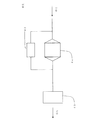
従来、エンジンの排ガスの温度が下がった際に触媒温度を高く保つ方法として、液状の熱媒体を用いる方法が提案されている(例えば、特許文献1を参照)。この方法は、排ガス温度の高いときに熱交換器を介して液状の熱媒体に熱を溜め、排ガス温度が低くなった際に、当該熱を溜めた熱媒体が流れる熱交換器によって、排ガス温度を高めたり触媒担体を暖めたりしようとするものである。 Conventionally, a method using a liquid heat medium has been proposed as a method for keeping the catalyst temperature high when the temperature of the exhaust gas of the engine decreases (see, for example, Patent Document 1). In this method, when the exhaust gas temperature is high, heat is accumulated in the liquid heat medium via the heat exchanger, and when the exhaust gas temperature becomes low, the heat exchanger through which the heat medium storing the heat flows flows to the exhaust gas temperature. Or to warm the catalyst support.
しかし、上記熱媒体を用いて排ガスや触媒担体を暖める方法では、液状の熱媒体を循環、コントロールするシステムが必要となるため、大掛かりなシステムを必要とし、それにより大きな搭載スペースを必要とし、更に、これらにより高コストになるという問題があった。 However, the method of heating exhaust gas and catalyst carrier using the above heat medium requires a system for circulating and controlling the liquid heat medium, which requires a large-scale system, which requires a large mounting space. However, there was a problem that the cost would be high.
更に、熱媒体として液体を使用するため、あまり高温にならず、蓄熱された熱を再利用する際に大きな温度差が得られないという問題があった。 Furthermore, since a liquid is used as the heat medium, there is a problem that the temperature does not become so high and a large temperature difference cannot be obtained when the stored heat is reused.
本発明は、上述した問題に鑑みてなされたものであり、エンジンから排出される排ガスの温度が低下した場合においても、必要な温度(触媒活性を発現させることができる温度)を維持することができるハニカム触媒体、及びこのようなハニカム触媒体を備えることにより、エンジンから排出される排ガスの温度が低下した場合においても、高い排ガス浄化性能を維持することができる排ガス浄化装置を提供することを目的とする。 The present invention has been made in view of the above-described problems, and can maintain a necessary temperature (a temperature at which catalytic activity can be exhibited) even when the temperature of exhaust gas discharged from an engine is lowered. A honeycomb catalyst body that can be provided, and an exhaust gas purification device that can maintain high exhaust gas purification performance even when the temperature of exhaust gas discharged from an engine is lowered by providing such a honeycomb catalyst body. Objective.
上述の課題を解決するため、本発明は、以下のハニカム触媒体及び排ガス浄化装置を提供する。 In order to solve the above-described problems, the present invention provides the following honeycomb catalyst body and exhaust gas purification device.
[1] 流体の流路となる一方の端面から他方の端面まで延びる複数のセルを区画形成する隔壁を有するハニカム部、及び前記ハニカム部の外周を取り囲むように配設された発熱部を有する筒状のハニカム基材と、前記発熱部内に配設され、通電により発熱可能な発熱体と、前記ハニカム部の前記隔壁に担持された触媒とを備え、前記ハニカム部と前記発熱部が焼結により接合されているハニカム触媒体(第1の発明)。
[2] 前記ハニカム基材の発熱部の熱伝導率及び熱容量が、前記ハニカム基材のハニカム部の熱伝導率及び熱容量より大きい[1]に記載のハニカム触媒体。
[1] A honeycomb part having a partition wall that partitions and forms a plurality of cells extending from one end face to the other end face that serves as a fluid flow path, and a cylinder having a heat generating part disposed so as to surround the outer periphery of the honeycomb part A honeycomb substrate, a heating element that is disposed in the heating part and can generate heat when energized, and a catalyst supported on the partition walls of the honeycomb part, the honeycomb part and the heating part being sintered A joined honeycomb catalyst body (first invention).
[2] The honeycomb catalyst body according to [1], wherein the heat conductivity and heat capacity of the heat generating portion of the honeycomb base material are larger than the heat conductivity and heat capacity of the honeycomb portion of the honeycomb base material.
[3] 流体の流路となる一方の端面から他方の端面まで延びる複数のセルを区画形成する隔壁を有するハニカム部、及び前記ハニカム部の外周を取り囲むように配設され、通電により発熱可能な発熱部を有する筒状のハニカム基材と、前記ハニカム部の前記隔壁に担持された触媒とを備え、前記ハニカム部と前記発熱部が焼結により接合されているハニカム触媒体であり、前記ハニカム基材の発熱部の熱伝導率及び熱容量が、前記ハニカム基材のハニカム部の熱伝導率及び熱容量より大きいハニカム触媒体(第2の発明)。 [ 3 ] A honeycomb part having partition walls that form a plurality of cells extending from one end face to the other end face that serves as a fluid flow path, and is disposed so as to surround the outer periphery of the honeycomb part, and can generate heat when energized. A honeycomb catalyst body comprising a cylindrical honeycomb substrate having a heat generating part and a catalyst supported on the partition walls of the honeycomb part, wherein the honeycomb part and the heat generating part are joined by sintering , A honeycomb catalyst body in which the heat conductivity and heat capacity of the heat generating portion of the base material are larger than the heat conductivity and heat capacity of the honeycomb portion of the honeycomb base material (second invention).
[4] 前記ハニカム基材の材料物性が、熱伝導率20W/mK以上、且つ熱容量1000J/m3K以上である[1]〜[3]のいずれかに記載のハニカム触媒体。 [ 4 ] The honeycomb catalyst body according to any one of [1] to [ 3], wherein the material properties of the honeycomb base material are a thermal conductivity of 20 W / mK or more and a heat capacity of 1000 J / m 3 K or more.
[5] 前記ハニカム部が、セルの延びる方向に直交する断面において、中央部と前記中央部を取り囲む外周部とから構成され、前記外周部の隔壁厚さが、前記中央部の隔壁厚さより厚い[1]〜[4]のいずれかに記載のハニカム触媒体。 [ 5 ] In the cross section orthogonal to the cell extending direction, the honeycomb portion is configured by a central portion and an outer peripheral portion surrounding the central portion, and a partition wall thickness of the outer peripheral portion is larger than a partition wall thickness of the central portion. The honeycomb catalyst body according to any one of [1] to [ 4 ].
[6] 前記外周部の隔壁厚さが、前記中央部の隔壁厚さの1.05〜2.00倍である[5]に記載のハニカム触媒体。 [ 6 ] The honeycomb catalyst body according to [ 5 ], wherein a partition wall thickness in the outer peripheral portion is 1.05 to 2.00 times a partition wall thickness in the central portion.
[7] [1]〜[6]のいずれかに記載のハニカム触媒体と、流体の流路となる一方の端面から他方の端面まで延びる複数のセルを区画形成する隔壁及び最外周に配設された外周壁を有する筒状のハニカム基材、並びに前記隔壁に担持された触媒を有する第2ハニカム触媒体と、前記ハニカム触媒体及び前記第2ハニカム触媒体を内部に収納した、一方の端部に入口開口部を有し、他方の端部に出口開口部を有する筒状の缶体と、前記ハニカム触媒体に通電するための電源とを備え、前記第2ハニカム触媒体が前記缶体の入口開口部側に配置され、前記ハニカム触媒体が前記缶体の出口開口部側に配置されるとともに、前記第2ハニカム触媒体と前記ハニカム触媒体とが、前記缶体の入口開口部から流入したガスが前記第2ハニカム触媒体の前記セルを通過した後に前記ハニカム触媒体の前記セルを通過するように、直列に配置された排ガス浄化装置。 [7] The honeycomb catalyst body according to any one of [1] to [6], a partition wall for partitioning a plurality of cells extending from one end face to the other end face to be a fluid flow path, and disposed on the outermost periphery A cylindrical honeycomb substrate having an outer peripheral wall formed therein, a second honeycomb catalyst body having a catalyst supported on the partition walls, and one end in which the honeycomb catalyst body and the second honeycomb catalyst body are housed. A cylindrical can body having an inlet opening at the other end and an outlet opening at the other end; and a power source for energizing the honeycomb catalyst body, wherein the second honeycomb catalyst body is the can body The honeycomb catalyst body is disposed on the outlet opening side of the can body, and the second honeycomb catalyst body and the honeycomb catalyst body are disposed from the inlet opening portion of the can body. The inflowing gas is the second honeycomb catalyst body. So as to pass through the cells of the honeycomb catalyst body after passing through the cell, the exhaust gas purifying device arranged in series.
[8] 前記ハニカム触媒体の前記ハニカム部の、セルの延びる方向に直交する断面における直径が、前記第2ハニカム触媒体の、セルの延びる方向に直交する断面における直径の0.9倍以上である[7]に記載の排ガス浄化装置。 [8] A diameter of the honeycomb portion of the honeycomb catalyst body in a cross section perpendicular to the cell extending direction is 0.9 times or more of a diameter of the second honeycomb catalyst body in a cross section orthogonal to the cell extending direction. The exhaust gas purifying apparatus according to [7].
本発明のハニカム触媒体は、「複数のセルを区画形成する隔壁を有するハニカム部、及びハニカム部の外周を取り囲むように配設された発熱部を有する筒状のハニカム基材」と、「前記発熱部内に配設され、通電により発熱可能な発熱体」と、「ハニカム部の隔壁に担持された触媒」とを備えるものであるため、排ガス浄化装置の一部として用いた場合に、エンジンから排出される排ガスの温度が低下しても、発熱部内の発熱体の発熱によって発熱部が加熱され、当該発熱部の熱がハニカム部に伝わって当該ハニカム部が加熱されることにより、触媒の温度、及びハニカム部を通過する際の排ガスの温度を高く維持することができる。 The honeycomb catalyst body of the present invention includes a “honeycomb portion having partition walls that define a plurality of cells, and a tubular honeycomb substrate having a heat generating portion disposed so as to surround the outer periphery of the honeycomb portion”, Since it is provided with a heating element disposed in the heat generating part and capable of generating heat when energized, and a “catalyst supported on the partition walls of the honeycomb part”, when used as a part of an exhaust gas purification device, Even if the temperature of the exhaust gas to be discharged is lowered, the heat generating part is heated by the heat generation of the heat generating element in the heat generating part, and the heat of the heat generating part is transmitted to the honeycomb part to heat the honeycomb part, so that the temperature of the catalyst is increased. And the temperature of the exhaust gas when passing through the honeycomb portion can be kept high.
本発明の排ガス浄化装置は、「上記本発明のハニカム触媒体」と、「流体の流路となる一方の端面から他方の端面まで延びる複数のセルを区画形成する隔壁及び最外周に配設された外周壁を有する筒状のハニカム基材、並びに隔壁に担持された触媒を有する第2ハニカム触媒体」と、「ハニカム触媒体及び第2ハニカム触媒体を内部に収納した、一方の端部に入口開口部を有し、他方の端部に出口開口部を有する筒状の缶体」と、前記ハニカム触媒体に通電するための電源とを備え、第2ハニカム触媒体が缶体の入口開口部側に配置され、ハニカム触媒体が缶体の出口開口部側に配置されるとともに、第2ハニカム触媒体とハニカム触媒体とが、「缶体の入口開口部から流入したガスが第2ハニカム触媒体のセルを通過した後にハニカム触媒体のセルを通過する」ように、直列に配置されたものであるため、排ガスの浄化を行う際に、エンジンから排出される排ガスの温度が低下しても、発熱部の発熱によって、触媒の温度、及びハニカム部を通過する際の排ガスの温度を高く維持することができる。 The exhaust gas purifying apparatus of the present invention is provided on the outermost periphery and the partition wall that partition and form “the honeycomb catalyst body of the present invention”, “a plurality of cells extending from one end surface to the other end surface that serve as a fluid flow path”. A cylindrical honeycomb substrate having an outer peripheral wall, and a second honeycomb catalyst body having a catalyst supported on partition walls, and a "honeycomb catalyst body and second honeycomb catalyst body housed inside, at one end portion A cylindrical can having an inlet opening and having an outlet opening at the other end ”and a power source for energizing the honeycomb catalyst body, wherein the second honeycomb catalyst body has an inlet opening of the can body The honeycomb catalyst body is disposed on the outlet opening side of the can body, and the second honeycomb catalyst body and the honeycomb catalyst body are configured such that “the gas flowing from the inlet opening of the can body is Honeycomb catalyst after passing through cell of catalyst body Since the exhaust gas is exhausted, the temperature of the catalyst is reduced by the heat generated by the heat generating part even when the temperature of the exhaust gas exhausted from the engine is reduced. And the temperature of the exhaust gas when passing through the honeycomb portion can be kept high.
次に本発明を実施するための形態を図面を参照しながら詳細に説明するが、本発明は以下の実施形態に限定されるものではなく、本発明の趣旨を逸脱しない範囲で、当業者の通常の知識に基づいて、適宜設計の変更、改良等が加えられることが理解されるべきである。 DETAILED DESCRIPTION OF THE PREFERRED EMBODIMENTS Next, embodiments for carrying out the present invention will be described in detail with reference to the drawings. However, the present invention is not limited to the following embodiments, and those skilled in the art do not depart from the spirit of the present invention. It should be understood that design changes, improvements, and the like can be made as appropriate based on ordinary knowledge.
(1)ハニカム触媒体(第1の発明):
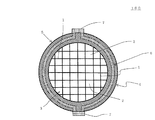
本発明のハニカム触媒体の一の実施形態は、図1〜図3に示すように、流体(排ガス)の流路となる一方の端面11から他方の端面12まで延びる複数のセル2を区画形成する隔壁1を有するハニカム部3、及びハニカム部3の外周を取り囲むように配設された発熱部4を有する筒状のハニカム基材5と、発熱部4内に配設され、通電により発熱可能な発熱体6と、ハニカム部3の隔壁1に担持された触媒とを備えるものである。図1は、本発明のハニカム触媒体の一の実施形態を模式的に示す斜視図である。図2は、本発明のハニカム触媒体の一の実施形態の、セルの延びる方向に平行な断面を示す模式図である。図3は、図2におけるA−A’断面を示す模式図である。
(1) Honeycomb catalyst body (first invention):
In one embodiment of the honeycomb catalyst body of the present invention, as shown in FIGS. 1 to 3, a plurality of
このように、本実施形態のハニカム触媒体100によれば、「ハニカム部3、及びハニカム部3の外周を取り囲むように配設された発熱部4を有する筒状のハニカム基材5と、発熱部4内に配設され、通電により発熱可能な発熱体6」を備えるため、排ガス浄化装置の一部として用いた場合に、エンジンから排出される排ガスの温度が低下しても、発熱部の発熱によって、触媒の温度、及びハニカム部を通過する際の排ガスの温度を高く維持することができる。本明細書において、「発熱部が発熱する」というときは、「発熱部内の発熱体の発熱によって発熱部が加熱され、加熱された発熱部から熱が発せられる状態」又は、「発熱部自体が(通電されることによって)発熱する状態」を意味する。本実施形体のハニカム触媒体100においては、「発熱部が発熱する」というときは、「発熱部内の発熱体の発熱によって発熱部が加熱され、加熱された発熱部から熱が発せられる状態」である。
As described above, according to the
本実施形態のハニカム触媒体は、排ガスの浄化に使用する際に、排ガスの温度が低いときに発熱部を発熱させて、ハニカム触媒体の触媒温度を触媒が活性化する温度に維持し、排ガスの温度が高くなったところで発熱部の発熱を停止させるように使用することが好ましい。 When the honeycomb catalyst body of the present embodiment is used for purification of exhaust gas, the heat generating portion is heated when the temperature of the exhaust gas is low, and the catalyst temperature of the honeycomb catalyst body is maintained at a temperature at which the catalyst is activated. It is preferable to use the heater so as to stop the heat generation when the temperature becomes high.
本実施形態のハニカム触媒体100は、発熱部4が、ハニカム基材5の、セルの延びる方向に直交する断面における外縁部分に配設されている。
In the
本実施形態のハニカム触媒体100は、ハニカム部3の外周を取り囲むように配設された発熱部4内に、通電することにより発熱する発熱体6が配設されている。発熱部4は、ハニカム部3のセルが開口する面を「ハニカム部の端面」としたときに、当該ハニカム部の端面を除く部分である外周部分の全体に配設されていることが好ましい。
In the
発熱体6は、ハニカム基材3の外周面に配設された2つの通電用端子7,7(正極側の通電用端子と、負極側の通電用端子)に接続され、通電用端子7を介して外部の電源から通電されるように形成されていることが好ましい。発熱体6は、通電されることにより発熱するものであれば特に限定されないが、例えば、図2、図3に示すように、ハニカム触媒体の中心軸に直交する断面において、リング状の発熱部4の形状に沿って、ハニカム部3を取り囲むように、リング状に形成されたものであることが好ましい。そして、発熱体は、ハニカム触媒体の中心軸方向に複数本並べられていることが好ましい。尚、「発熱体6がリング状に形成されている」というときは、発熱体6がリング状に形成されている状態、又は、発熱体6が2つの通電用端子7,7(正極側の通電用端子と、負極側の通電用端子)を介して繋がれることにより、全体として輪(リング)が形成された状態であることを意味する。また、発熱部4がリング状であるというときは、棒状又は板状の部材を湾曲させてリング状に形成した状態であることを意味する。
The
リング状の発熱体6は、発熱部4内に、1〜20本配設されていることが好ましく、3〜6本配設されていることが更に好ましい。これにより、発熱体6によって、発熱部4を均等に加熱することができる。また、発熱部4をより均等に発熱させるために、発熱体6は、等間隔に配設することが好ましい。
It is preferable that 1 to 20 ring-shaped
発熱体6の材質としては、珪素−炭化珪素複合材(炭化珪素粒子を珪素で結合させたもの)、Ni及びFeを主成分とする合金、タングステンを主成分とする合金、カーバイド、アルミニウム、銅等を挙げることができる。また、発熱体6の、通電用端子7,7間の抵抗は、0.1〜100Ωであることが好ましく、0.1〜30Ωであることが更に好ましい。これにより、発熱体6は、電流を流したときに(通電したときに)、300〜700℃程度に発熱する。
The material of the
本実施形体のハニカム触媒体100においては、2つの通電用端子7,7(正極側の通電用端子と、負極側の通電用端子)が、ハニカム触媒体100のセルの延びる方向に直交する断面において、ハニカム触媒体100の中心を通る一の直線と、ハニカム触媒体の外周(発熱部の外周)とが交わる位置(2箇所)に、それぞれ配設されていることが好ましい。通電用端子7は、ハニカム基材5の外周面に、長手方向がセルの延びる方向に向くように配設された、帯状の部材であることが好ましい。通電用端子7の材質としては、珪素−炭化珪素複合材(炭化珪素粒子を珪素で結合させたもの)、Ni及びFeを主成分とする合金、タングステンを主成分とする合金、ニクロム、Cu、Fe、Ag、Au等を挙げることができる。
In the
本実施形体のハニカム触媒体100においては、ハニカム基材5の材料物性が、熱伝導率20W/mK以上、且つ熱容量1000J/m3K以上であることが好ましく、「熱伝導率40W/mK以上、且つ熱容量2000J/m3K以上」であることが更に好ましい。ハニカム基材の熱伝導率は、高いほど熱の伝導が速くなるため好ましいが、上限としては、300W/mK程度となる。また、ハニカム基材の熱容量は、高いほど蓄熱効果があるため好ましいが、上限としては、4000J/m3K程度となる。ここで、材料物性とは、ハニカム基材から切り出した板状のサンプルの物性を意味する。
In the
ハニカム基材5の熱伝導率が20W/mKより小さいと、発熱部4で発生した熱をハニカム部に伝わる速度が遅くなることがある。ハニカム基材5の熱容量が1000J/m3Kより小さいと、発熱部4の蓄熱効果が小さいため、発生した熱を有効に使用し難くなることがある。尚、ハニカム部の熱容量は、ハニカム部を構成する隔壁の熱容量である。
If the thermal conductivity of the
ハニカム基材5の発熱部4の厚さt(図2参照)が、ハニカム基材5の「セル1の延びる方向に直交する断面における」直径D(図2参照)の、0.03〜0.5倍であることが好ましく、0.04〜0.5倍であることが更に好ましい。厚さtが、直径Dの0.03倍より薄いと、発熱部4の蓄熱効果が低下するため、発生した熱を有効に使用し難くなることがある。厚さtが、直径Dの0.5倍より厚いと、発熱部4の昇温に長時間を要することがあり、排ガスの温度低下に対し、タイミング良く発熱部の発熱機能を利用できないことがある。
The thickness t (see FIG. 2) of the
本実施形体のハニカム触媒体100においては、ハニカム基材5の体積抵抗率は、108Ωm以上であることが好ましく、108〜1013Ωmであることが更に好ましい。体積抵抗率が108Ωmより小さいと、ハニカム基材に電流が多量に流れてしまい、ハニカム基材が不均一に発熱し、温度勾配による熱応力で破損することがある。
In the
本実施形態のハニカム触媒体100においては、ハニカム基材5の気孔率が、40%以下であることが好ましく、5%以下であることが更に好ましく、1%以下が特に好ましい。ハニカム基材5の気孔率が40%より大きいと、熱伝導率及び熱容量が低くなるため、好ましくない。また、ハニカム基材5の気孔率が、5%以下であるということは、ハニカム基材の材質が、緻密質であることを示している。ハニカム基材5の気孔率が5%以下であると、ハニカム基材5の熱伝導率及び熱容量を、より高くすることができる。ハニカム基材5の気孔率とは、「ハニカム部3の隔壁」及び発熱部4の気孔率のことである。気孔率は、水銀ポロシメータにより測定した値である。ハニカム基材5の気孔率は、0%であってもよいが、実質的には、0.1%程度が下限値となる。
In the
本実施形態のハニカム触媒体100において、ハニカム部3の隔壁1の平均細孔径は、50μm以下であることが好ましく、6μm以下であることが更に好ましい。平均細孔径が50μmより大きいと、発熱部の熱伝導率及び熱容量が低下することがある。平均細孔径は、水銀ポロシメータにより測定した値である。
In the
本実施形態のハニカム触媒体100は、ハニカム部3の隔壁1の厚さが0.05〜0.3mmであることが好ましく、0.05〜0.2mmであることが更に好ましい。隔壁1の厚さが0.05mmより薄いと、ハニカム触媒体の強度が低下することがあり、また、発熱部で発生した熱が、ハニカム部の隔壁を通じて触媒や排ガスに伝達され難くなることがある。隔壁厚さが0.3mmより厚いと、ハニカム触媒体100に排ガスを流したときの圧力損失が大きくなることがある。
In the
本実施形態のハニカム触媒体100は、セル密度が30〜200セル/cm2であることが好ましく、30〜95セル/cm2であることが更に好ましい。セル密度が30セル/cm2より低いと、ハニカム触媒体の強度が低下することがあり、また、発熱部で発生した熱が、ハニカム部の隔壁を通じて触媒や排ガスに伝達され難くなることがある。セル密度が200セル/cm2より高いと、ハニカム触媒体100に排ガスを流したときの圧力損失が大きくなることがある。
The
本実施形態のハニカム触媒体100においては、ハニカム部及び発熱部の材質が、炭化珪素、珪素−炭化珪素複合材(炭化珪素粒子が珪素によって結合されたもの)、窒化珪素又は窒化アルミニウム、を主成分とするものであることが好ましい。ここで、「主成分」とは、全体の90質量%以上含有される成分である。更に、ハニカム部及び発熱部の材質は、緻密質窒化珪素(気孔率1%以下)、緻密質再結晶炭化珪素(気孔率1%以下)、又は緻密質珪素−炭化珪素複合材(気孔率1%以下)であることが好ましい。本実施形態のハニカム触媒体100においては、ハニカム部と発熱部との間に熱膨張差が生じないようにするという観点から、ハニカム部の材質と発熱部の材質とが同じであることが好ましい。
In the
本実施形態のハニカム触媒体100においては、ハニカム部の熱膨張係数と発熱部の熱膨張係数とが近い値であることが好ましい。これにより、温度変化時の熱膨張差による熱応力によってクラックが発生する、ことを防止することができる。
In the
本実施形態のハニカム触媒体100においては、ハニカム部と発熱部とが、焼結されることにより接合されていることが好ましい。これにより、ハニカム部と発熱部との境界部分においても、熱の伝達が遮られることなく、効率的に熱を伝えることができる。尚、ハニカム部と発熱部とが、焼結されることにより接合されている場合、ハニカム部と発熱部との境界部分に明確な界面は形成されず、ハニカム部と発熱部とが連続的に繋がっていることが好ましい。
In the
本実施形態のハニカム触媒体100は、セル2の延びる方向に直交する断面におけるセル2の形状は、特に限定されるものではないが、四角形、六角形、八角形等の多角形であることが好ましい。セル形状をこのようにすることにより、排ガスを流したときの圧力損失が小さく、触媒の浄化性能が優れるという利点がある。
In the
本実施形態のハニカム触媒体100の形状は、底面が円形の筒状(円筒形状)であることが好ましい。また、ハニカム触媒体の大きさは、底面の直径が80〜200mmであることが好ましい。また、ハニカム触媒体の中心軸方向の長さは、50〜300mmであることが好ましい。また、本実施形態のハニカム触媒体100においては、ハニカム部3の形状が、底面が円形の筒状(円筒形状)であることが好ましい。
The shape of the
本実施形体のハニカム触媒体100は、ハニカム部の隔壁に担持された触媒を備えているか、または触媒自体をハニカム状に形成したものが好ましい。担持される触媒としては、三元触媒、NOX浄化触媒、酸化触媒、炭化水素吸着剤等を挙げることができる。三元触媒としては、Pt、Pd、Rh等の貴金属を、アルミナ、セリア等を主成分とする担体に担持したもの、またはこれに炭化水素吸着成分としてゼオライト等を含有させたもの等を挙げることができる。NOX浄化触媒としては、Ptと、「NOX吸蔵成分としてのBa又はK」とを、アルミナを主成分とする担体に担持したもの、「FeまたはCuにより金属置換されたゼオライト」を主成分とするもの、等を挙げることができる。触媒の担持量は、ハニカム部の単位体積あたり60〜400g/リットルが好ましい。触媒自体でハニカム触媒体を形成する例としては、ゼオライト製ハニカム触媒体、アルミナ製ハニカム触媒体等を挙げることができ、これらは、セラミック繊維を含有させて強度を向上したものであってもよい。
The
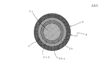
次に本発明のハニカム触媒体の他の実施形態について説明する。図4に示すように、本発明のハニカム触媒体の他の実施形態は、ハニカム部3が、セルの延びる方向に直交する断面において、中央部3aと中央部3aを取り囲む外周部3bとから構成され、外周部3bの隔壁厚さが、中央部3aの隔壁厚さより厚い。このように、外周部3bの隔壁厚さが、中央部3aの隔壁厚さより厚いことにより、発熱部で発生した熱を、短時間でハニカム部の隔壁に伝達することが可能となる。尚、本実施形態のハニカム触媒体200は、ハニカム部3において、外周部3bの隔壁厚さが、中央部3aの隔壁厚さより厚いこと以外の条件は、上記本発明のハニカム触媒体の一の実施形態と同じであることが好ましい。図4は、本発明のハニカム触媒体の他の実施形態の、セルの延びる方向に直交する断面を示す模式図である。
Next, another embodiment of the honeycomb catalyst body of the present invention will be described. As shown in FIG. 4, in another embodiment of the honeycomb catalyst body of the present invention, the
本実施形体のハニカム触媒体200は、外周部の隔壁厚さが、中央部の隔壁厚さの1.05〜2.00倍であることが好ましく、1.1〜1.5倍であることが更に好ましい。1.05倍より薄いと、熱伝導の速度が遅くなることがあり、2.00倍より厚いと、圧力損失が大きくなることがある。
In the
また、セルの延びる方向に直交する断面において、ハニカム部3の中央部3aの直径が、ハニカム部3の直径の0.3〜0.7倍であることが好ましい。0.3倍より小さいと、圧力損失が大きくなることがあり、0.7倍より大きいと、熱伝導の速度が遅くなることがある。
Moreover, it is preferable that the diameter of the center part 3a of the
次に本発明のハニカム触媒体の更に他の実施形態について説明する。本実施形態のハニカム触媒体は、図5に示すように、セルの延びる方向に直交する断面において、ハニカム部3が、中央部3aと、中央部3aの外周に「同心円を描くように配設された」2層の外周層3bα,3bβを有するものであり、中央部3a、外周層3bβ、外周層3bαの順に、外側の層ほど隔壁が厚く形成されたものである。本実施形態のハニカム触媒体300は、外周層3bα,3bβによって、外周部3bが構成されている。これにより、排ガスの熱を、隔壁を通じて、発熱部に、より短時間で伝達することが可能となり、更に、発熱部に蓄えられた熱を、短時間でハニカム部の隔壁に伝達することが可能となる。本実施形態のハニカム触媒体は、外周層が2層であるが、2層に限定されず、複数層であって外側の層ほど隔壁の厚さが厚いものであればよい。尚、本実施形態のハニカム触媒体300は、ハニカム部3において、外周部3bが、外周層3bα,3bβによって形成されていること以外は、上記本発明のハニカム触媒体の他の実施形態(ハニカム触媒体200(図4参照))と同じであることが好ましい。図5は、本発明のハニカム触媒体の更に他の実施形態の、セルの延びる方向に直交する断面を示す模式図である。尚、図5においては、ハニカム部3におけるセル及び隔壁、並びに発熱部4に配設された発熱体及び通電用端子は省略されている。
Next, still another embodiment of the honeycomb catalyst body of the present invention will be described. In the honeycomb catalyst body of the present embodiment, as shown in FIG. 5, in the cross section orthogonal to the cell extending direction, the
また、本発発明のハニカム触媒体の更に他の実施形態として、セルの延びる方向に直交する断面において、ハニカム部の隔壁が、外周部分が最も厚く、中心部分が最も薄く形成され、外周部分から中心部分に向かって連続的に薄くなるように形成されているものを挙げることができる。これにより、発熱部で発生した熱を、短時間でハニカム部の隔壁に伝達することが可能となる。尚、本実施形態のハニカム触媒体は、ハニカム部の隔壁が、外周部分が最も厚く、中心部分が最も薄く形成され、外周部分から中心部分に向かって連続的に薄くなるように形成されていること以外の条件は、上記本発明のハニカム触媒体の一の実施形態と同じであることが好ましい。 Further, as still another embodiment of the honeycomb catalyst body of the present invention, in the cross section orthogonal to the cell extending direction, the partition wall of the honeycomb part is formed with the thickest outer peripheral part and the thinnest central part, and from the outer peripheral part. The thing formed so that it may become thin continuously toward a center part can be mentioned. As a result, the heat generated in the heat generating part can be transmitted to the partition walls of the honeycomb part in a short time. In the honeycomb catalyst body of the present embodiment, the partition walls of the honeycomb part are formed such that the outer peripheral part is the thickest, the central part is the thinnest, and the outer peripheral part is continuously thinned from the central part. The other conditions are preferably the same as in the embodiment of the honeycomb catalyst body of the present invention.
次に、本発明のハニカム触媒体の更に他の実施形態について説明する。本実施形態のハニカム触媒体は、ハニカム基材の発熱部の熱伝導率及び熱容量が、ハニカム基材のハニカム部の熱伝導率及び熱容量より大きいものである。これにより、発熱部の蓄熱効果をより向上させることができる。尚、本実施形態のハニカム触媒体は、ハニカム基材の発熱部の熱伝導率及び熱容量が、ハニカム基材のハニカム部の熱伝導率及び熱容量より大きいこと以外の条件は、上記本発明のハニカム触媒体の一の実施形態と同じであることが好ましい。 Next, still another embodiment of the honeycomb catalyst body of the present invention will be described. In the honeycomb catalyst body of the present embodiment, the heat conductivity and heat capacity of the heat generating portion of the honeycomb base material are larger than the heat conductivity and heat capacity of the honeycomb portion of the honeycomb base material. Thereby, the heat storage effect of the heat generating part can be further improved. The honeycomb catalyst body of the present embodiment is the same as that of the above-described honeycomb structure of the present invention except that the heat conductivity and heat capacity of the heating part of the honeycomb base material are larger than the heat conductivity and heat capacity of the honeycomb part of the honeycomb base material. It is preferable that it is the same as that of one embodiment of a catalyst body.
本実施形態のハニカム触媒体においては、ハニカム部の材質が、炭化珪素、珪素−炭化珪素複合材又は窒化珪素を主成分とするものであることが好ましい。また、発熱部の材質は、銅、青銅、アルミニウム、珪素等の金属Aであることが好ましい。また、発熱部の材質としては、緻密質窒化珪素(気孔率1%以下)、緻密質再結晶炭化珪素(気孔率1%以下)、緻密質珪素−炭化珪素複合材(気孔率1%以下)等のセラミックBであることが好ましい。また、セラミックBと、銅、青銅、アルミニウム、珪素等の金属との、複合体Cであってもよい。さらに、発熱部の材質としては、上記セラミックB又は複合体Cに、熱容量の高いセラミック粒子(例えば、ジルコニア、燐酸ジルコニウム)又は熱容量の高いセラミック繊維(例えば、ジルコニア繊維、燐酸ジルコニウム繊維)を混合した複合体Bを挙げることができる。
In the honeycomb catalyst body of the present embodiment, it is preferable that the material of the honeycomb portion is mainly composed of silicon carbide, a silicon-silicon carbide composite material, or silicon nitride. The material of the heat generating part is preferably a metal A such as copper, bronze, aluminum, or silicon. Further, as the material of the heat generating portion, dense silicon nitride (
(2)ハニカム触媒体(第2の発明):
本発明のハニカム触媒体(第2の発明)の一の実施形態(ハニカム触媒体400、図8参照)は、流体の流路となる一方の端面から他方の端面まで延びる複数のセルを区画形成する隔壁を有するハニカム部、及びハニカム部の外周を取り囲むように配設され、通電により発熱可能な発熱部を有する筒状のハニカム基材と、ハニカム部の隔壁に担持された触媒とを備えるものである。図8は、本発明の排ガス浄化装置の更に他の実施形態(排ガス浄化装置700)の、ガスが流れる方向に平行な断面を示す模式図である。排ガス浄化装置700は、ハニカム触媒体として、本発明のハニカム触媒体(第2の発明)の一の実施形態(ハニカム触媒体400)を用いたものである。
(2) Honeycomb catalyst body (second invention):
In one embodiment (
本実施形体のハニカム触媒体は、発熱体によって発熱部を発熱させる代わりに、発熱体を有さずに「発熱部自体が通電により発熱する」こと以外の条件は、上記「第1の発明のハニカム触媒体」における各条件と同じであることが好ましい。 The honeycomb catalyst body of the present embodiment has the same conditions as those described in the “first invention” except that the heating element does not have a heating element and the heating element itself generates heat by energization instead of heating the heating element by the heating element. The conditions are preferably the same as those in the “honeycomb catalyst body”.
本実施形体のハニカム触媒体は、発熱部に通電することにより、発熱部自体を発熱させることができるものである。発熱部は、通電の際の電気抵抗が0.1〜100Ωであることが好ましい。0.1Ωより小さいと、発熱が不十分になることがある。100Ωより大きいと、電気が流れ難くなり、発熱が不十分となることがある。 The honeycomb catalyst body of the present embodiment can heat the heat generating portion itself by energizing the heat generating portion. The heat generating part preferably has an electric resistance of 0.1 to 100Ω when energized. If it is less than 0.1Ω, heat generation may be insufficient. If it is greater than 100Ω, it becomes difficult for electricity to flow, and heat generation may be insufficient.
発熱部の材質としては、緻密質窒化珪素(気孔率1%以下)、緻密質再結晶炭化珪素(気孔率1%以下)、緻密質珪素−炭化珪素複合材(気孔率1%以下)等のセラミックBを主成分とすることが好ましい。また、セラミックBと、銅、青銅、アルミニウム、珪素等の金属との、複合体Cであってもよい。さらに、発熱部の材質としては、上記セラミックB又は複合体Cに、熱容量の高いセラミック粒子(例えば、ジルコニア、燐酸ジルコニウム)又は熱容量の高いセラミック繊維(例えば、ジルコニア繊維、燐酸ジルコニウム繊維)を混合した複合体Bを挙げることができる。
As the material of the heat generating part, dense silicon nitride (
(3)排ガス浄化装置:
次に、本発明の排ガス浄化装置の一の実施形態について説明する。
(3) Exhaust gas purification device:
Next, an embodiment of the exhaust gas purification apparatus of the present invention will be described.
本実施形体の排ガス浄化装置は、図6に示すように、上記本発明のハニカム触媒体の一の実施形態(ハニカム触媒体100)と、流体の流路となる一方の端面から他方の端面まで延びる複数のセル22を区画形成する隔壁21及び最外周に配設された外周壁23を有する筒状のハニカム基材25、並びに隔壁21に担持された触媒を有する第2ハニカム触媒体24と、ハニカム触媒体100及び第2ハニカム触媒体24を内部に収納した、一方の端部に入口開口部31を有し、他方の端部に出口開口部32を有する筒状の缶体33と、ハニカム触媒体100に通電するための電源36とを備え、第2ハニカム触媒体24が缶体33の入口開口部31側に配置され、ハニカム触媒体100が缶体33の出口開口部32側に配置されるとともに、第2ハニカム触媒体24とハニカム触媒体100とが、「缶体33の入口開口部31から流入したガスGが第2ハニカム触媒体24のセル22を通過した後にハニカム触媒体100のセル2を通過する」ように、直列に配置されたものである。図6は、本発明の排ガス浄化装置の一の実施形態の、ガスが流れる方向に平行な断面を示す模式図である。
As shown in FIG. 6, the exhaust gas purifying apparatus of the present embodiment has one embodiment (honeycomb catalyst body 100) of the honeycomb catalyst body of the present invention and from one end surface serving as a fluid flow path to the other end surface. A
このように、本実施形体の排ガス浄化装置500は、上記のように構成されているため、排ガスの浄化を行う際に、エンジンから排出される排ガスの温度が低下しても、発熱部4が発生する熱によって、触媒の温度を高く維持することができる。排ガス浄化装置500に排ガスを流したときには、「ガス(排ガス)温度、ハニカム触媒体の温度、及び第2ハニカム触媒体の温度」は、例えば、図9に示されるようなグラフで表される。図9は、排ガス浄化装置500に排ガスを流したときの、ガス(排ガス)温度、ハニカム触媒体の温度及び第2ハニカム触媒体の温度の、それぞれの変化を示すグラフである。図9においては、横軸がガス(排ガス)を流す時間を示し、縦軸が温度を示す。また、図9において、横軸に平行に引かれた直線は、「触媒活性温度」を示し、当該触媒活性温度より温度が高い場合に、触媒が、触媒活性を示し、排ガス浄化機能を示す。また、図9においては、時間T1を過ぎると、ハニカム触媒体の温度が第2ハニカム触媒体の温度より高くなるため、時間T1を過ぎると、ハニカム触媒体による排ガス浄化が主として行われるようになる。尚、時間T1において、ハニカム触媒体の発熱部の発熱体に通電し、発熱体を発熱させている。そして、時間T2を過ぎると、ハニカム触媒体の温度は「触媒活性温度」より高いが、第2ハニカム触媒体の温度が「触媒活性温度」より低くなるため、時間T2を過ぎると、ハニカム触媒体による排ガス浄化のみが行われることになる。図9は、排ガス温度が低い、エンジンの運転初期の段階で、ハニカム触媒体を早期に昇温するために、ハニカム触媒体の発熱部の発熱体に通電し、発熱体を発熱させていることを示している。
Thus, since the exhaust
本実施形体の排ガス浄化装置は、上記本発明のハニカム触媒体の一の実施形態を備えるものであるが、本発明のハニカム触媒体(第1の発明又は第2の発明)を備えていればよく、上記本発明のハニカム触媒体の他の実施形態等のいずれの実施形態を備えていてもよい。 The exhaust gas purifying apparatus of the present embodiment has one embodiment of the honeycomb catalyst body of the present invention, but if the honeycomb catalyst body of the present invention (first invention or second invention) is provided. In addition, any embodiment such as another embodiment of the honeycomb catalyst body of the present invention may be provided.
本実施形体の排ガス浄化装置500においては、第2ハニカム触媒体24としては、特に限定されず、ハニカム形状の基材に触媒が担持されて形成された公知のハニカム触媒体を用いることができる。例えば以下のようなものが好ましい。
In the exhaust
本実施形体の排ガス浄化装置500を構成するハニカム触媒体24は、上記のように、流体の流路となる一方の端面から他方の端面まで延びる複数のセル22を区画形成する隔壁21及び最外周に配設された外周壁23を有する筒状のハニカム基材25、並びに隔壁21に担持された触媒を有するものである。
As described above, the
ハニカム基材25のセル密度は、60〜180セル/cm2であることが好ましく60〜95セル/cm2であることが更に好ましい。セル密度が60セル/cm2未満であると、排ガスとの接触効率が低くなることがある。セル密度が180セル/cm2を超えると、圧力損失が増大することがある。
The cell density of the
ハニカム基材25の隔壁21の厚さは、0.05〜0.20mmであることが好ましく、0.05〜0.16mmであることが更に好ましい。隔壁の厚さが、0.05mm未満であると、強度が不足して耐熱衝撃性が低下することがあり、0.20mmを超えると、圧力損失が増大することがある。
The thickness of the partition walls 21 of the
ハニカム基材25の隔壁21は緻密質であっても多孔質であってもよい。隔壁21は多孔質であると、隔壁の細孔内にも触媒を担持することができ、触媒の担持量を増やすことができる。隔壁21が多孔質の場合、隔壁21の平均細孔径は、0.5〜6.0μmであることが好ましい。隔壁の平均細孔径は、水銀ポロシメータ(水銀圧入法)によって測定した値である。また、隔壁21が多孔質の場合、隔壁21の気孔率は、0.01〜5.0%であることが好ましい。隔壁の平均細孔径は、水銀ポロシメータ(水銀圧入法)によって測定した値である。
The partition walls 21 of the
第2ハニカム触媒体24を構成するハニカム基材25の材質としては、セラミックを主成分とするものであることが好ましい。セラミックとしては、炭化珪素、珪素−炭化珪素複合材、コージェライト、アルミニウムタイタネート、サイアロン、ムライト、窒化珪素、リン酸ジルコニウム、ジルコニア、チタニア、アルミナ、若しくはシリカ、又はこれらを組み合わせたものを好適例として挙げることができる。特に、炭化珪素、珪素−炭化珪素複合材、コージェライト、ムライト、窒化珪素、アルミナ等のセラミックスが、耐アルカリ特性上好適である。なかでも酸化物系のセラミックスは、コストが安い点でも好ましい。
The material of the
第2ハニカム触媒体24(ハニカム基材25)の、中心軸に直交する断面の形状は、特に限定されないが、例えば、円形、楕円形、長円形、四角形、六角形等を挙げることができる。なかでも、円形が好ましい。また、第2ハニカム触媒体24(ハニカム基材25)の、中心軸に直交する断面の形状は、ハニカム触媒体100の、中心軸に直交する断面の形状と同じであることが好ましい。
The shape of the cross section perpendicular to the central axis of the second honeycomb catalyst body 24 (honeycomb substrate 25) is not particularly limited, and examples thereof include a circle, an ellipse, an oval, a quadrangle, a hexagon, and the like. Of these, a circular shape is preferable. In addition, the shape of the cross section of the second honeycomb catalyst body 24 (honeycomb substrate 25) perpendicular to the central axis is preferably the same as the shape of the cross section of the
第2ハニカム触媒体24(ハニカム基材25)の大きさは、特に限定されないが、底面の直径が80〜200mmであることが好ましい。また、第2ハニカム触媒体24(ハニカム基材25)の中心軸方向の長さは、50〜300mmであることが好ましい。 The size of the second honeycomb catalyst body 24 (honeycomb substrate 25) is not particularly limited, but the bottom diameter is preferably 80 to 200 mm. The length of the second honeycomb catalyst body 24 (honeycomb substrate 25) in the central axis direction is preferably 50 to 300 mm.
本実施形態の排ガス浄化装置500においては、第2ハニカム触媒体24に担持される触媒の種類及び担持量としては、上記本発明のハニカム触媒体(第1の発明)の一の実施形態(ハニカム触媒体100(図1参照))において、好ましいとされた触媒の種類及び担持量を挙げることができる。
In the exhaust
また、第2ハニカム触媒体には、炭化水素吸着機能を有する成分がコートされていることが好ましい。また、炭化水素吸着成分自体でハニカム触媒体が作製されていることも好ましい態様である。炭化水素は低温でハニカム触媒体に吸着し、ハニカム触媒体の温度が上昇すると離脱するため、排気ガスの温度が低いエンジン運転初期に、多量に発生する未燃焼燃料(炭化水素)が第2ハニカム触媒体に吸着し、排気ガス温度が上昇したときに、炭化水素が第2ハニカム触媒体から離脱する。このとき、第2ハニカム触媒体の温度が触媒活性温度まで上昇していれば、炭化水素を第2ハニカム触媒体で酸化処理することができるが、第2ハニカム触媒体は触媒活性温度まで昇温されていない場合がある。このような場合には、ハニカム触媒体に通電することによりハニカム触媒体の温度を触媒活性温度まで速やかに上昇させることにより、第2ハニカム触媒体から離脱してきた炭化水素をハニカム触媒体100によって充分に酸化処理することができる。
The second honeycomb catalyst body is preferably coated with a component having a hydrocarbon adsorption function. It is also a preferable aspect that the honeycomb catalyst body is made of the hydrocarbon adsorbing component itself. Since the hydrocarbon adsorbs on the honeycomb catalyst body at a low temperature and desorbs when the temperature of the honeycomb catalyst body rises, a large amount of unburned fuel (hydrocarbon) is generated in the second honeycomb at the initial stage of engine operation when the exhaust gas temperature is low. When adsorbed on the catalyst body and the exhaust gas temperature rises, hydrocarbons are detached from the second honeycomb catalyst body. At this time, if the temperature of the second honeycomb catalyst body is raised to the catalyst activation temperature, the hydrocarbon can be oxidized by the second honeycomb catalyst body, but the second honeycomb catalyst body is heated to the catalyst activation temperature. May not have been. In such a case, by energizing the honeycomb catalyst body, the temperature of the honeycomb catalyst body is rapidly raised to the catalyst activation temperature, so that the hydrocarbon separated from the second honeycomb catalyst body is sufficiently absorbed by the
また、図7に示す排ガス浄化装置600のように、ハニカム触媒体100のハニカム基材5のハニカム部3の底面の直径は、第2ハニカム触媒体24(ハニカム基材)の底面の直径の0.9倍以上であることが好ましく、0.9〜0.98倍であることが更に好ましい。これにより、ハニカム触媒体24をガスが通過する際の圧力損失の低下を防止することができる。図7は、本発明の排ガス浄化装置の他の実施形態の、ガスが流れる方向に平行な断面を示す模式図である。
Further, as in the exhaust
図6に示される本実施形体の排ガス浄化装置500においては、ハニカム触媒体100と第2ハニカム触媒体24との間の距離は、1〜50mmであることが好ましい。1mmより短いと、使用時に、ハニカム触媒体100と第2ハニカム触媒体24とが接触して破損することがある。50mmより長いと、ハニカム触媒体100と第2ハニカム触媒体24との間から、熱が逃げ易くなることがある。
In the exhaust
本実施形体の排ガス浄化装置500は、ハニカム触媒体100及び第2ハニカム触媒体24を内部に収納した、一方の端部に入口開口部31を有し、他方の端部に出口開口部32を有する筒状の缶体33を備えている。そして、第2ハニカム触媒体24が缶体33の入口開口部31側に配置され、ハニカム触媒体100が缶体33の出口開口部32側に配置されるとともに、第2ハニカム触媒体24とハニカム触媒体100とが、「缶体33の入口開口部31から流入したガスGが第2ハニカム触媒体24のセル22を通過した後にハニカム触媒体100のセル2を通過する」ように、直列に配置されている。第2ハニカム触媒体24は、ガスGが缶体33の入口開口部31から流入する場合における、上流側に配置され、ハニカム触媒体100は、ガスGが缶体33の入口開口部31から流入する場合における、下流側に配置されている。また、本実施形体の排ガス浄化装置500は、第2ハニカム触媒体とハニカム触媒体とが、第2ハニカム触媒体24の一方の端面が缶体33の入口開口部31側を向き、第2ハニカム触媒体24の他方の端面とハニカム触媒体100の一方の端面とが対向し、ハニカム触媒体100他方の端面が缶体33の出口開口部32側を向くように、缶体33内に配置されているということもできる。
The exhaust
本実施形体の排ガス浄化装置500において、缶体33は、一方の端部に入口開口部31を有し、他方の端部に出口開口部32を有する筒状である。缶体33の形状は、ハニカム触媒体及び第2ハニカム触媒体の形状に合わせて、適宜決定することができる。例えば、缶体33のガスの流れる方向における長さは、ハニカム触媒体のセルの延びる方向における長さと第2ハニカム触媒体のセルの延びる方向における長さとの和の、1.1〜1.5倍であることが好ましい。1.1倍より短いと、ハニカム触媒体及び第2ハニカム触媒体を収納し難くなることがある。1.5倍より長いと、排ガス浄化装置が大きくなり過ぎることがある。また、缶体33の、ハニカム触媒体が挿入される部分の、中心軸に直交する断面の直径は、ハニカム触媒体の中心軸に直交する断面の直径の、1.05〜1.1倍であることが好ましい。また、缶体33の、第2ハニカム触媒体が挿入される部分の、中心軸に直交する断面の直径は、第2ハニカム触媒体の中心軸に直交する断面の直径の、1.1〜1.3倍であることが好ましい。
In the exhaust
缶体33の材質は、特に限定されず、例えば、鉄、ステンレス鋼等を挙げることができる。また、缶体33には、電源36と通電用端子7とを接続する電線を通すための孔が、形成されていることが好ましい。
The material of the can 33 is not particularly limited, and examples thereof include iron and stainless steel. Moreover, it is preferable that a hole for passing an electric wire connecting the
本実施形体の排ガス浄化装置500においては、ハニカム触媒体100及び第2ハニカム触媒体24は、外周に充填材35を配設した状態で、筒体33内に収納されている。ハニカム触媒体100及び第2ハニカム触媒体24は、充填材35を圧縮した状態で、筒体33内に収納されていることが好ましい。充填材35としては、特に限定されないが、耐熱無機絶縁マット等を挙げることができる。また、ハニカム触媒体100及び第2ハニカム触媒体24は、「缶体33の内側に、内側に向かって突き出るように取り付けられた」留め具34によって、筒体33内で動かないように固定されていることが好ましい。留め具34の材質としては、特に限定されず、鉄、ステンレス鋼等を挙げることができる。
In the exhaust
本実施形体の排ガス浄化装置500は、ハニカム触媒体に通電するための電源36を備えている。電源36は、電線によって通電用端子又は発熱部に接続されている。電源36の電圧は、12〜250Vが好ましい。特に、高電圧の電池電源を有するハイブリッド車輌では200V以上の電源が好ましい。電源36の種類としては、鉛蓄電池、ニッケル水素電池、リチウムイオン電池、ナトリウム−硫黄電池等を挙げることができる。
The exhaust
(4)ハニカム触媒体(第1の発明)の製造方法:
次に、本発明のハニカム触媒体(第1の発明)の一の実施形態の製造方法について説明する。
(4) Manufacturing method of honeycomb catalyst body (first invention):
Next, a manufacturing method of one embodiment of the honeycomb catalyst body (first invention) of the present invention will be described.
まず、炭化珪素粉末(炭化珪素)に、金属珪素粉末(金属珪素)、バインダ、界面活性剤、水等を添加して成形原料を作製することが好ましい。炭化珪素粉末の質量と金属珪素の質量との合計に対して、金属珪素の質量が10〜30質量%となるようにすることが好ましい。尚、使用する原料は、作製しようとするハニカム触媒体のハニカム基材が、所望の材質となるように、適宜決定することができ、例えば、ハニカム基材の材質を窒化珪素とする場合には、炭化珪素粉末及び金属珪素粉末の代わりに、窒化珪素粉末を用いる。 First, it is preferable to prepare a forming raw material by adding metal silicon powder (metal silicon), a binder, a surfactant, water, or the like to silicon carbide powder (silicon carbide). It is preferable that the mass of the metal silicon is 10 to 30% by mass with respect to the total of the mass of the silicon carbide powder and the mass of the metal silicon. The raw material to be used can be appropriately determined so that the honeycomb base material of the honeycomb catalyst body to be manufactured is a desired material. For example, when the material of the honeycomb base material is silicon nitride Instead of silicon carbide powder and metal silicon powder, silicon nitride powder is used.
バインダとしては、メチルセルロース、ヒドロキシプロポキシルセルロース、ヒドロキシエチルセルロース、カルボキシメチルセルロース、ポリビニルアルコール等を挙げることができる。これらの中でも、メチルセルロースとヒドロキシプロポキシルセルロースとを併用することが好ましい。バインダの含有量は、炭化珪素粉末の質量と金属珪素の質量との合計を100質量部としたときに、1〜10質量部であることが好ましい。 Examples of the binder include methyl cellulose, hydroxypropoxyl cellulose, hydroxyethyl cellulose, carboxymethyl cellulose, and polyvinyl alcohol. Among these, it is preferable to use methyl cellulose and hydroxypropoxyl cellulose in combination. The content of the binder is preferably 1 to 10 parts by mass when the total of the mass of the silicon carbide powder and the mass of the metal silicon is 100 parts by mass.
水の含有量は、炭化珪素粉末の質量と金属珪素の質量との合計を100質量部としたときに、20〜35質量部であることが好ましい。 The water content is preferably 20 to 35 parts by mass when the total of the mass of the silicon carbide powder and the mass of metal silicon is 100 parts by mass.
界面活性剤としては、エチレングリコール、デキストリン、脂肪酸石鹸、ポリアルコール等を用いることができる。これらは、1種単独で使用してもよいし、2種以上を組み合わせて使用してもよい。界面活性剤の含有量は、炭化珪素粉末の質量と金属珪素の質量との合計を100質量部としたときに、0.1〜5質量部であることが好ましい。 As the surfactant, ethylene glycol, dextrin, fatty acid soap, polyalcohol and the like can be used. These may be used individually by 1 type and may be used in combination of 2 or more type. The content of the surfactant is preferably 0.1 to 5 parts by mass when the total of the mass of the silicon carbide powder and the mass of the metal silicon is 100 parts by mass.
次に、成形原料を混練して坏土を形成する。成形原料を混練して坏土を形成する方法としては特に制限はなく、例えば、ニーダー、真空土練機等を用いる方法を挙げることができる。 Next, the forming raw material is kneaded to form a clay. There is no restriction | limiting in particular as a method of kneading | mixing a shaping | molding raw material and forming a clay, For example, the method of using a kneader, a vacuum clay kneader, etc. can be mentioned.
次に、坏土を押出成形してハニカム成形体を形成する。押出成形に際しては、所望の全体形状、セル形状、隔壁厚さ、セル密度等を有する口金を用いることが好ましい。口金の材質としては、摩耗し難い超硬合金が好ましい。ハニカム成形体は、流体の流路となる複数のセルを区画形成する多孔質の隔壁と最外周に位置する外周壁とを有する構造である。 Next, the kneaded material is extruded to form a honeycomb formed body. In extrusion molding, it is preferable to use a die having a desired overall shape, cell shape, partition wall thickness, cell density and the like. As the material of the die, a cemented carbide which does not easily wear is preferable. The honeycomb formed body has a structure having porous partition walls that define and form a plurality of cells serving as fluid flow paths and an outer peripheral wall located at the outermost periphery.
ハニカム成形体の隔壁厚さ、セル密度、外周壁の厚さ等は、乾燥、焼成における収縮を考慮し、作製しようとする本発明のハニカム触媒体の構造に合わせて適宜決定することができる。 The partition wall thickness, cell density, outer peripheral wall thickness, and the like of the honeycomb formed body can be appropriately determined according to the structure of the honeycomb catalyst body of the present invention to be manufactured in consideration of shrinkage during drying and firing.
例えば、ハニカム部に相当する部分のみを備えたハニカム成形体を形成することが好ましい。ハニカム部に相当する部分のみを備えたハニカム成形体を形成した場合には、別途、発熱部に相当する部分を成形して、当該発熱部に相当する部分を、ハニカム部に相当する部分を備えたハニカム成形体に巻き付け、その後、焼成することが好ましい。この場合、発熱部に相当する部分は、押出し法、テープ成形法、鋳込み法等の方法で成形することが好ましい。また、ハニカム部に相当する部分と発熱部に相当する部分を備えたハニカム成形体を形成してもよい。 For example, it is preferable to form a honeycomb formed body having only a portion corresponding to the honeycomb portion. In the case where a honeycomb molded body having only a portion corresponding to the honeycomb portion is formed, a portion corresponding to the heat generating portion is separately formed, and a portion corresponding to the heat generating portion is provided with a portion corresponding to the honeycomb portion. It is preferable that the honeycomb formed body is wound and then fired. In this case, the portion corresponding to the heat generating portion is preferably formed by a method such as an extrusion method, a tape forming method, or a casting method. In addition, a honeycomb formed body having a portion corresponding to the honeycomb portion and a portion corresponding to the heat generating portion may be formed.
発熱部(発熱部形成用成形体)内に発熱体(発熱体形成用成形体)を配設する方法としては、以下のような方法を挙げることができる。発熱部に相当する部分を作製する際には、まず、上記「ハニカム部に相当する部分のみを備えたハニカム成形体」を作製する場合と同一の条件で杯土を作製し、得られた坏土から複数のリング状の成形体(発熱部用リング状成形体)を形成することが好ましい。 Examples of the method of disposing the heating element (heating element forming molded body) in the heating section (heating element forming molded body) include the following methods. When producing the portion corresponding to the heat generating portion, first, a clay was produced under the same conditions as in the case of producing the above-mentioned “honeycomb molded body having only the portion corresponding to the honeycomb portion”. It is preferable to form a plurality of ring-shaped molded bodies (ring-shaped molded bodies for heat generating portions) from the soil.
そして、発熱体を珪素−炭化珪素複合材で作製する場合は、「炭化珪素に対する金属ケイ素の含有比率を変えて、電気伝導率を変える」こと以外は、「ハニカム部に相当する部分のみを備えたハニカム成形体」を作製する場合と同様の条件で杯土を作製し、得られた坏土を押出し成形することにより、棒状の可塑性成形体を形成することが好ましい。また、坏土をテープ成形することにより、テープ状(細幅の板状)の可塑性成形体を形成してもよい。可塑性成形体は複数作製することが好ましい。次に、得られた可塑性成形体をリング状に形成し、発熱体形成用成形体を得ることが好ましい。 When the heating element is made of a silicon-silicon carbide composite material, except that “the electric conductivity is changed by changing the content ratio of metal silicon to silicon carbide”, only “the portion corresponding to the honeycomb portion is provided. It is preferable to form a rod-shaped plastic molded body by preparing a clay under the same conditions as in the case of manufacturing the “honeycomb molded body” and extruding the obtained clay. Further, a tape-shaped (narrow plate-shaped) plastic molded body may be formed by tape-molding the clay. It is preferable to produce a plurality of plastic molded bodies. Next, it is preferable to obtain the molded body for forming a heating element by forming the obtained plastic molded body into a ring shape.
そして、複数の発熱部用リング状成形体を、発熱体形成用成形体を間に挟みながら、それぞれの中心軸を揃えて(同軸となるように)積層し、中心軸方向に加圧することにより、内部に発熱体形成用成形体を含む筒状の発熱部形成用成形体を得ることが好ましい。 Then, by laminating a plurality of ring-shaped molded bodies for heat generating parts with the central axes thereof being aligned (coaxial) while sandwiching the molded bodies for heating element formation therebetween, and pressurizing in the direction of the central axis In addition, it is preferable to obtain a cylindrical heat generating part forming compact that includes a heat generating element forming compact inside.
そして、得られた筒状の発熱部形成用成形体の内面に、発熱部用リング状成形体を作製する際に用いた坏土に更に水及び分散剤を加えたスラリーを塗布し、「ハニカム部に相当する部分のみを備えたハニカム成形体」を、筒状の発熱部形成用成形体の内部に挿入して、発熱部形成用成形体を含むハニカム成形体を得ることが好ましい。 Then, a slurry in which water and a dispersant were further added to the clay used in producing the ring-shaped molded body for the heat generating portion was applied to the inner surface of the obtained cylindrical heat-generating portion forming molded body. It is preferable to obtain a honeycomb formed body including the heat generating portion forming molded body by inserting the honeycomb formed body having only a portion corresponding to the portion into a cylindrical heat generating portion forming formed body.
また、発熱体を珪素−炭化珪素複合材で作製する場合、以下の方法を用いてもよい。まず、「ハニカム部に相当する部分のみを備えたハニカム成形体」を作製する場合と同様の条件で杯土を作製する。次に、得られた坏土から、複数の、リング状の発熱体形成用成形体を作製する。その後、発熱体形成用成形体を焼成して発熱体形成用焼成体を作製する。その後、発熱体形成用焼成体に金属珪素を含浸させて珪素含浸発熱体形成用焼成体を作製する。そして、複数の発熱部用リング状成形体を、珪素含浸発熱体形成用焼成体を間に挟みながら積層し、発熱部形成用成形体を得るようにする。 Moreover, when producing a heat generating body with a silicon- silicon carbide composite material, you may use the following method. First, a clay is produced under the same conditions as in the case of producing “a honeycomb formed body having only a portion corresponding to the honeycomb portion”. Next, a plurality of ring-shaped molded bodies for forming a heating element are produced from the obtained clay. Thereafter, the heating element-forming molded body is fired to produce a heating element-forming fired body. Thereafter, the fired body for forming a heating element is impregnated with metallic silicon to produce a fired body for forming a silicon-impregnated heating element. Then, a plurality of ring-shaped molded bodies for heat generating portions are stacked while sandwiching a fired body for forming silicon-impregnated heat generating members, thereby obtaining a molded body for forming heat generating portions.
また、発熱体を金属で作成する場合は、金属製の発熱体をプレス成形、または鋳込み法により成形し、ダイスによりリング形状にすることが好ましい。その後は、上記「発熱体を珪素−炭化珪素複合材で作製する場合」と同様にして、発熱部形成用成形体を含むハニカム成形体を得ることが好ましい。 Moreover, when producing a heat generating body with a metal, it is preferable to shape | mold a metal heat generating body by press molding or the casting method, and make it ring shape with a die | dye. After that, it is preferable to obtain a honeycomb formed body including the heat generating portion forming formed body in the same manner as in the above-mentioned “when the heat generating body is made of a silicon-silicon carbide composite material”.
また、発熱部(発熱部形成用成形体)内に発熱体(発熱体形成用成形体)を配設する他の方法としては、まず、上記「ハニカム部に相当する部分のみを備えたハニカム成形体」を作製する場合と同一の条件で杯土を作製し、得られた坏土から複数のリング状の成形体(発熱部用リング状成形体)を形成し、発熱部用リング状成形体の中心軸方向における端面に発熱体形成用材料として「金属含有ペースト」又は「珪素及び炭化珪素を含有するスラリー」を塗布することが好ましい。そして、発熱体形成用材料が塗布された複数の発熱部用リング状成形体を、それぞれの中心軸を揃えて(同軸となるように)積層し、中心軸方向に加圧することにより、内部に発熱体形成用材料を含む筒状の発熱部形成用成形体を得ることが好ましい。そして、得られた筒状の発熱部形成用成形体の内面に、発熱部用リング状成形体を作製する際に用いた坏土に更に水及び分散剤を加えたスラリーを塗布し、「ハニカム部に相当する部分のみを備えたハニカム成形体」を、筒状の発熱部形成用成形体の内部に挿入して、発熱部形成用成形体を含むハニカム成形体を得ることが好ましい。 As another method for disposing the heating element (heating element forming molded body) in the heating section (heating element forming molded body), first, the above-mentioned “honeycomb molding provided with only the portion corresponding to the honeycomb section” The clay is produced under the same conditions as in the case of producing the “body”, and a plurality of ring-shaped molded bodies (ring-shaped molded bodies for the heat-generating part) are formed from the obtained clay, and the ring-shaped molded body for the heat-generating part. It is preferable to apply “metal-containing paste” or “slurry containing silicon and silicon carbide” as a heating element forming material to the end face in the central axis direction. Then, a plurality of heat generating part ring-shaped molded bodies coated with a heat generating element forming material are laminated with their respective central axes aligned (coaxial), and pressurized in the direction of the central axis, thereby internally It is preferable to obtain a cylindrical heating part forming molded body containing a heating element forming material. Then, a slurry in which water and a dispersant were further added to the clay used in producing the ring-shaped molded body for the heat generating portion was applied to the inner surface of the obtained cylindrical heat-generating portion forming molded body. It is preferable to obtain a honeycomb formed body including the heat generating portion forming molded body by inserting the honeycomb formed body having only a portion corresponding to the portion into a cylindrical heat generating portion forming formed body.
得られたハニカム成形体について、焼成前に乾燥を行うことが好ましい。乾燥の方法は特に限定されず、例えば、マイクロ波加熱乾燥、高周波誘電加熱乾燥等の電磁波加熱方式と、熱風乾燥、過熱水蒸気乾燥等の外部加熱方式とを挙げることができる。これらの中でも、成形体全体を迅速かつ均一に、クラックが生じないように乾燥することができる点で、電磁波加熱方式で一定量の水分を乾燥させた後、残りの水分を外部加熱方式により乾燥させることが好ましい。乾燥の条件として、電磁波加熱方式にて、乾燥前の水分量に対して、30〜99質量%の水分を除いた後、外部加熱方式にて、3質量%以下の水分にすることが好ましい。電磁波加熱方式としては、誘電加熱乾燥が好ましく、外部加熱方式としては、熱風乾燥が好ましい。 The obtained honeycomb formed body is preferably dried before firing. The drying method is not particularly limited, and examples thereof include an electromagnetic heating method such as microwave heating drying and high-frequency dielectric heating drying, and an external heating method such as hot air drying and superheated steam drying. Among these, the entire molded body can be dried quickly and uniformly without cracks, and after drying a certain amount of moisture with an electromagnetic heating method, the remaining moisture is dried with an external heating method. It is preferable to make it. As drying conditions, it is preferable to remove moisture of 30 to 99% by mass with respect to the amount of moisture before drying by an electromagnetic heating method, and then to make the moisture to 3% by mass or less by an external heating method. As the electromagnetic heating method, dielectric heating drying is preferable, and as the external heating method, hot air drying is preferable.
次に、ハニカム成形体の中心軸方向長さが、所望の長さではない場合は、両端面(両端部)を切断して所望の長さとすることが好ましい。切断方法は特に限定されないが、丸鋸切断機等を用いる方法を挙げることができる。 Next, when the length of the honeycomb formed body in the central axis direction is not a desired length, it is preferable to cut both end faces (both end portions) to a desired length. The cutting method is not particularly limited, and examples thereof include a method using a circular saw cutting machine.
次に、ハニカム成形体を焼成して、ハニカム焼成体を作製することが好ましい。焼成の前に、バインダ等を除去するため、仮焼成を行うことが好ましい。仮焼成は大気雰囲気において、400〜500℃で、0.5〜20時間行うことが好ましい。仮焼成及び焼成の方法は特に限定されず、電気炉、ガス炉等を用いて焼成することができる。焼成条件は、窒素、アルゴン等の不活性雰囲気において、1400〜1500℃で、1〜20時間加熱することが好ましい。 Next, the honeycomb fired body is preferably fired to produce a honeycomb fired body. In order to remove the binder or the like before firing, it is preferable to perform temporary firing. Pre-baking is preferably performed at 400 to 500 ° C. for 0.5 to 20 hours in an air atmosphere. The method of temporary baking and baking is not particularly limited, and baking can be performed using an electric furnace, a gas furnace, or the like. The firing conditions are preferably 1400 to 1500 ° C. for 1 to 20 hours in an inert atmosphere such as nitrogen or argon.
次に、得られたハニカム焼成体に触媒を担持して、ハニカム触媒体を形成することが好ましい。触媒の担持方法は、特に限定されず、公知の方法で担持することができる。例えば、先ず、所定の触媒を含有する触媒スラリーを調製する。次いで、この触媒スラリーを、吸引法等の方法により、ハニカム焼成体の隔壁表面にコートする。その後、室温又は加熱条件下で乾燥することにより、ハニカム触媒体を得ることができる。触媒スラリーのスラリー濃度は、10〜50質量%であることが好ましい。 Next, it is preferable to form a honeycomb catalyst body by supporting a catalyst on the obtained honeycomb fired body. The method for supporting the catalyst is not particularly limited, and the catalyst can be supported by a known method. For example, first, a catalyst slurry containing a predetermined catalyst is prepared. Next, the catalyst slurry is coated on the partition wall surfaces of the honeycomb fired body by a method such as a suction method. Then, a honeycomb catalyst body can be obtained by drying at room temperature or under heating conditions. The slurry concentration of the catalyst slurry is preferably 10 to 50% by mass.
ハニカム焼成体に担持する触媒は、上記本発明のハニカム触媒体の一の実施形態において、好ましいとされた触媒であることが好ましい。 The catalyst supported on the honeycomb fired body is preferably a catalyst that is considered preferable in one embodiment of the honeycomb catalyst body of the present invention.
尚、ハニカム部及び発熱部の材質が、珪素−炭化珪素複合材以外の場合、上記製造方法において、以下の条件を取り入れる(採用する)ことが好ましい。 In addition, when the material of the honeycomb part and the heat generating part is other than the silicon-silicon carbide composite material, it is preferable to incorporate (adopt) the following conditions in the manufacturing method.
まず、窒化アルミニウム等のセラミックス原料紛と、「イットリア(Y2O3)、シリカ(SiO2)、マグネシア(MgO)、アルミナ(Al2O3)等」の焼結助剤原料紛とを、所定の配合比で調合し、ポットミルあるいはボールミル等を用いて混合する。混合は湿式、乾式のいずれでもよく、湿式を用いた場合は、混合後乾燥を行い、原料混合紛を得る。この後、原料混合紛、又は「原料混合粉にバインダを加えて造粒したもの」に水を添加して成形原料とする。そして、成形原料を混練して坏土とする。そして、ハニカム部と発熱部とを別々に成形する場合には、坏土を押出成形することにより「ハニカム部に相当する部分のみを備えたハニカム成形体」を形成することが好ましい。また、発熱部用リング状成形体は、例えば、金型成形法、CIP(Cold Isostatic Pressing)法、スリップキャスト法等の方法により形成することが好ましい。 First, a ceramic raw material powder such as aluminum nitride and a sintering aid raw material powder such as “yttria (Y 2 O 3 ), silica (SiO 2 ), magnesia (MgO), alumina (Al 2 O 3 )”, Mix at a predetermined mixing ratio and mix using a pot mill or ball mill. Mixing may be either wet or dry. When wet is used, drying is performed after mixing to obtain a raw material mixed powder. Thereafter, water is added to the raw material mixed powder, or “the raw material mixed powder obtained by adding a binder and granulated” to obtain a forming raw material. Then, the forming raw material is kneaded to form a clay. When the honeycomb portion and the heat generating portion are separately formed, it is preferable to form a “honeycomb formed body having only a portion corresponding to the honeycomb portion” by extruding the clay. Moreover, it is preferable to form the ring-shaped molded body for a heat generating part by a method such as a mold molding method, a CIP (Cold Isostatic Pressing) method, a slip casting method, or the like.
「発熱体形成用成形体を含むハニカム成形体」又は「発熱体形成用材料を含むハニカム成形体」を焼成する際には、窒化アルミニウムをハニカム部及び発熱部の原料として用いる場合には、常圧焼結法等を用い、約1700℃〜約1900℃で焼結させることが好ましい。また、アルミナをハニカム部及び発熱部の原料として用いる場合には、常圧焼結法等を用い、約1600℃で焼結させることが好ましい。また、窒化珪素又はサイアロンをハニカム部及び発熱部の原料として用いる場合には、常圧焼結法等を用い、約1700℃〜約1850℃で焼結させることが好ましい。また、炭化珪素をハニカム部及び発熱部の原料として用いる場合には、常圧焼結法等を用い、約2000℃〜約2200℃で焼結させることが好ましい。 When firing a “honeycomb molded body including a heating element-forming molded body” or “honeycomb molded body including a heating element-forming material”, when aluminum nitride is used as a raw material for the honeycomb section and the heating section, it is usually used. It is preferable to sinter at about 1700 ° C. to about 1900 ° C. using a pressure sintering method or the like. Further, when alumina is used as a raw material for the honeycomb portion and the heat generating portion, it is preferable to sinter at about 1600 ° C. using an atmospheric pressure sintering method or the like. When silicon nitride or sialon is used as a raw material for the honeycomb part and the heat generating part, it is preferably sintered at about 1700 ° C. to about 1850 ° C. using a normal pressure sintering method or the like. In addition, when silicon carbide is used as a raw material for the honeycomb portion and the heat generating portion, it is preferable to sinter at about 2000 ° C. to about 2200 ° C. using a normal pressure sintering method or the like.
(5)ハニカム触媒体(第2の発明)の製造方法:
本発明のハニカム触媒体(第2の発明)の一の実施形態の製造方法は、発熱体及び通電用端子を作製しないこと以外は、上記本発明のハニカム触媒体(第1の発明)の一の実施形態の製造方法と同様であることが好ましい。そして、発熱部の通電の際の電気抵抗が、0.1〜100Ωになるようにすることが好ましい。
(5) Manufacturing method of honeycomb catalyst body (second invention):
The manufacturing method of one embodiment of the honeycomb catalyst body of the present invention (second invention) is one of the honeycomb catalyst bodies of the present invention (first invention) except that the heating element and the energization terminal are not produced. It is preferable to be the same as the manufacturing method of the embodiment. And it is preferable to make it the electrical resistance at the time of electricity supply of a heat generating part to be 0.1-100 (ohm).
(6)排ガス浄化装置の製造方法:
(6−1)ハニカム触媒体;
本発明の排ガス浄化装置を構成するハニカム触媒体は、上記本発明のハニカム触媒体(第1の発明又は第2の発明)の製造方法によって作製することが好ましい。
(6) Manufacturing method of exhaust gas purification device:
(6-1) honeycomb catalyst body;
The honeycomb catalyst body constituting the exhaust gas purifying apparatus of the present invention is preferably manufactured by the method for manufacturing the honeycomb catalyst body of the present invention (the first invention or the second invention).
(6−2)第2ハニカム触媒体;
まず、セラミック原料、バインダ、界面活性剤、造孔材、水等を添加して成形原料を作製することが好ましい。セラミック原料としては、炭化珪素、珪素−炭化珪素複合材、コージェライト化原料、コージェライト、アルミナタイタネート、サイアロン、ムライト、窒化珪素、リン酸ジルコニウム、ジルコニア、チタニア、アルミナ、シリカ、及びLAS(リチウムアルミニウムシリケート)又はこれらを組み合わせたものを好適例として挙げることができる。ここで、コージェライト化原料とは、焼成によりコージェライトとなる原料を意味し、シリカが42〜56質量%、アルミナが30〜45質量%、マグネシアが12〜16質量%の範囲に入る化学組成となるように配合されたセラミックス原料である。具体的にはタルク、カオリン、仮焼カオリン、アルミナ、水酸化アルミニウム、及びシリカの中から選ばれた複数の無機原料を上記化学組成となるような割合で含むものが挙げられる。
(6-2) Second honeycomb catalyst body;
First, it is preferable to prepare a forming raw material by adding a ceramic raw material, a binder, a surfactant, a pore former, water and the like. Ceramic raw materials include silicon carbide, silicon-silicon carbide composite material, cordierite forming raw material, cordierite, alumina titanate, sialon, mullite, silicon nitride, zirconium phosphate, zirconia, titania, alumina, silica, and LAS (lithium) Aluminum silicate) or a combination thereof can be mentioned as a suitable example. Here, the cordierite-forming raw material means a raw material that becomes cordierite by firing, and a chemical composition in which silica is in the range of 42 to 56 mass%, alumina is 30 to 45 mass%, and magnesia is in the range of 12 to 16 mass%. It is a ceramic raw material blended so that. Specific examples include those containing a plurality of inorganic raw materials selected from talc, kaolin, calcined kaolin, alumina, aluminum hydroxide, and silica in a proportion such that the above chemical composition is obtained.
バインダとしては、メチルセルロース、ヒドロキシプロポキシルセルロース、ヒドロキシエチルセルロース、カルボキシメチルセルロース、ポリビニルアルコール等を挙げることができる。これらの中でも、メチルセルロースとヒドロキシプロポキシルセルロースとを併用することが好ましい。バインダの含有量は、セラミック原料を100質量部としたときに、1〜10質量部であることが好ましい。 Examples of the binder include methyl cellulose, hydroxypropoxyl cellulose, hydroxyethyl cellulose, carboxymethyl cellulose, and polyvinyl alcohol. Among these, it is preferable to use methyl cellulose and hydroxypropoxyl cellulose in combination. The binder content is preferably 1 to 10 parts by mass when the ceramic raw material is 100 parts by mass.
造孔材としては、焼成工程により飛散消失する性質のものであればよく、コークス等の無機物質や発泡樹脂等の高分子化合物、澱粉等の有機物質等を単独で用いるか、組み合わせて用いることができる。造孔材の含有量は、セラミック原料を100質量部としたときに、1〜10質量部であることが好ましい。 As the pore former, any material that can be scattered and disappeared by the firing process may be used, and an inorganic substance such as coke, a polymer compound such as foamed resin, an organic substance such as starch, etc. may be used alone or in combination. Can do. The pore former content is preferably 1 to 10 parts by mass when the ceramic raw material is 100 parts by mass.
水の含有量は、セラミック原料を100質量部としたときに、20〜35質量部であることが好ましい。 The water content is preferably 20 to 35 parts by mass when the ceramic raw material is 100 parts by mass.
界面活性剤としては、エチレングリコール、デキストリン、脂肪酸石鹸、ポリアルコール等を用いることができる。これらは、1種単独で使用してもよいし、2種以上を組み合わせて使用してもよい。界面活性剤の含有量は、セラミック原料を100質量部としたときに、0.1〜5質量部であることが好ましい。 As the surfactant, ethylene glycol, dextrin, fatty acid soap, polyalcohol and the like can be used. These may be used individually by 1 type and may be used in combination of 2 or more type. The content of the surfactant is preferably 0.1 to 5 parts by mass when the ceramic raw material is 100 parts by mass.
次に、成形原料を混練して坏土を形成する。成形原料を混練して坏土を形成する方法としては特に制限はなく、例えば、ニーダー、真空土練機等を用いる方法を挙げることができる。 Next, the forming raw material is kneaded to form a clay. There is no restriction | limiting in particular as a method of kneading | mixing a shaping | molding raw material and forming a clay, For example, the method of using a kneader, a vacuum clay kneader, etc. can be mentioned.
次に、坏土を押出成形して第2ハニカム成形体を形成する。押出成形に際しては、所望の全体形状、セル形状、隔壁厚さ、セル密度等を有する口金を用いることが好ましい。口金の材質としては、摩耗し難い超硬合金が好ましい。第2ハニカム成形体は、流体の流路となる複数のセルを区画形成する隔壁と最外周に位置する外周壁とを有する構造である。 Next, the kneaded material is extruded to form a second honeycomb formed body. In extrusion molding, it is preferable to use a die having a desired overall shape, cell shape, partition wall thickness, cell density and the like. As the material of the die, a cemented carbide which does not easily wear is preferable. The second honeycomb formed body has a structure having partition walls for partitioning and forming a plurality of cells serving as fluid flow paths and an outer peripheral wall located at the outermost periphery.
第2ハニカム成形体の隔壁厚さ、セル密度、外周壁の厚さ等は、乾燥、焼成における収縮を考慮し、作製しようとする第2ハニカム触媒体の構造に合わせて適宜決定することができる。 The partition wall thickness, cell density, outer peripheral wall thickness, and the like of the second honeycomb molded body can be appropriately determined in accordance with the structure of the second honeycomb catalyst body to be manufactured in consideration of shrinkage during drying and firing. .
得られた第2ハニカム成形体について、焼成前に乾燥を行うことが好ましい。乾燥の方法は特に限定されず、例えば、マイクロ波加熱乾燥、高周波誘電加熱乾燥等の電磁波加熱方式と、熱風乾燥、過熱水蒸気乾燥等の外部加熱方式とを挙げることができる。これらの中でも、成形体全体を迅速かつ均一に、クラックが生じないように乾燥することができる点で、電磁波加熱方式で一定量の水分を乾燥させた後、残りの水分を外部加熱方式により乾燥させることが好ましい。乾燥の条件として、電磁波加熱方式にて、乾燥前の水分量に対して、30〜99質量%の水分を除いた後、外部加熱方式にて、3質量%以下の水分にすることが好ましい。電磁波加熱方式としては、誘電加熱乾燥が好ましく、外部加熱方式としては、熱風乾燥が好ましい。 The obtained second honeycomb formed body is preferably dried before firing. The drying method is not particularly limited, and examples thereof include an electromagnetic heating method such as microwave heating drying and high-frequency dielectric heating drying, and an external heating method such as hot air drying and superheated steam drying. Among these, the entire molded body can be dried quickly and uniformly without cracks, and after drying a certain amount of moisture with an electromagnetic heating method, the remaining moisture is dried with an external heating method. It is preferable to make it. As drying conditions, it is preferable to remove moisture of 30 to 99% by mass with respect to the amount of moisture before drying by an electromagnetic heating method, and then to make the moisture to 3% by mass or less by an external heating method. As the electromagnetic heating method, dielectric heating drying is preferable, and as the external heating method, hot air drying is preferable.
次に、第2ハニカム成形体の中心軸方向長さが、所望の長さではない場合は、両端面(両端部)を切断して所望の長さとすることが好ましい。切断方法は特に限定されないが、丸鋸切断機等を用いる方法を挙げることができる。 Next, when the length of the second honeycomb formed body in the central axis direction is not a desired length, it is preferable to cut both end faces (both end portions) to a desired length. The cutting method is not particularly limited, and examples thereof include a method using a circular saw cutting machine.
次に、第2ハニカム成形体を焼成して、第2ハニカム焼成体を作製することが好ましい。焼成の前に、バインダ等を除去するため、仮焼成を行うことが好ましい。仮焼成は大気雰囲気において、400〜500℃で、0.5〜20時間行うことが好ましい。仮焼成及び焼成の方法は特に限定されず、電気炉、ガス炉等を用いて焼成することができる。焼成条件は、窒素、アルゴン等の不活性雰囲気において、1400〜1500℃で、1〜20時間加熱することが好ましい。 Next, it is preferable to fabricate the second honeycomb fired body by firing the second honeycomb formed body. In order to remove the binder or the like before firing, it is preferable to perform temporary firing. Pre-baking is preferably performed at 400 to 500 ° C. for 0.5 to 20 hours in an air atmosphere. The method of temporary baking and baking is not particularly limited, and baking can be performed using an electric furnace, a gas furnace, or the like. The firing conditions are preferably 1400 to 1500 ° C. for 1 to 20 hours in an inert atmosphere such as nitrogen or argon.
次に、得られた第2ハニカム焼成体に触媒を担持して、第2ハニカム触媒体を形成することが好ましい。触媒の担持方法は、特に限定されず、公知の方法で担持することができる。例えば、先ず、所定の触媒を含有する触媒スラリーを調製する。次いで、この触媒スラリーを、吸引法等の方法により、第2ハニカム焼成体の隔壁表面にコートする。その後、室温又は加熱条件下で乾燥することにより、第2ハニカム触媒体を得ることができる。触媒スラリーのスラリー濃度は、10〜50質量%であることが好ましい。 Next, it is preferable to form a second honeycomb catalyst body by supporting the catalyst on the obtained second honeycomb fired body. The method for supporting the catalyst is not particularly limited, and the catalyst can be supported by a known method. For example, first, a catalyst slurry containing a predetermined catalyst is prepared. Next, the catalyst slurry is coated on the partition wall surfaces of the second honeycomb fired body by a method such as a suction method. Thereafter, the second honeycomb catalyst body can be obtained by drying at room temperature or under heating conditions. The slurry concentration of the catalyst slurry is preferably 10 to 50% by mass.
第2ハニカム焼成体に担持する触媒は、上記本発明の排ガス浄化装置の一の実施形態を構成する第2ハニカム触媒体に担持される触媒として好ましいとされたものであることが好ましい。 The catalyst supported on the second honeycomb fired body is preferably one that is preferable as a catalyst supported on the second honeycomb catalyst body constituting one embodiment of the exhaust gas purification apparatus of the present invention.
(6−3)排ガス浄化装置;
ハニカム触媒体及び第2ハニカム触媒体に充填材を巻きつけ、充填材を圧縮した状態で、ハニカム触媒体及び第2ハニカム触媒体を缶体内に収納し、電源を通電用端子に接続することにより、図6に示すような、排ガス浄化装置500を得ることが好ましい。缶体、充填材及び電源としては、上記本発明の排ガス浄化装置の一の実施形態を構成する缶体及び充填材として好ましいとされたものであることが好ましい。
(6-3) Exhaust gas purification device;
By wrapping the filler around the honeycomb catalyst body and the second honeycomb catalyst body, compressing the filler, storing the honeycomb catalyst body and the second honeycomb catalyst body in the can, and connecting the power source to the energization terminal It is preferable to obtain an exhaust
以下、本発明を実施例によって更に具体的に説明するが、本発明はこれらの実施例によって何ら限定されるものではない。 EXAMPLES Hereinafter, the present invention will be described more specifically with reference to examples, but the present invention is not limited to these examples.
(実施例1)
(1)ハニカム触媒体:
セラミック原料として、窒化珪素(Si3N4)、これに、焼結助剤としてイットリア(Y2O3)、炭酸マグネシウム、アルミナ(Al2O3)、バインダとしてヒドロキシプロピルメチルセルロースを添加すると共に、水を添加してボールミル等を用いて混合することにより成形原料を得た。得られた成形原料を混練し、真空土練機により円柱状の坏土を作製した。バインダの含有量はセラミック原料100質量に対して7質量部であり、イットリア(Y2O3)、炭酸マグネシウム、及びアルミナ(Al2O3)の含有量は、セラミック原料100質量部に対して、それぞれ1質量部であり、水の含有量はセラミック原料100質量部に対して42質量部であった。窒化珪素粉末の平均粒子径は5μmであった。平均粒子径はレーザー回折法で測定した値である。
Example 1
(1) Honeycomb catalyst body:
While adding silicon nitride (Si 3 N 4 ) as a ceramic raw material, yttria (Y 2 O 3 ), magnesium carbonate, alumina (Al 2 O 3 ) as a sintering aid, and hydroxypropylmethylcellulose as a binder, A molding raw material was obtained by adding water and mixing using a ball mill or the like. The obtained forming raw material was kneaded and a columnar clay was produced with a vacuum kneader. The binder content is 7 parts by mass with respect to 100 parts by mass of the ceramic raw material, and the yttria (Y 2 O 3 ), magnesium carbonate, and alumina (Al 2 O 3 ) contents are with respect to 100 parts by mass of the ceramic raw material. The amount of water was 42 parts by mass with respect to 100 parts by mass of the ceramic raw material. The average particle size of the silicon nitride powder was 5 μm. The average particle diameter is a value measured by a laser diffraction method.
得られた円柱状の坏土を押出成形機を用いて成形し、ハニカム成形体を得た。得られたハニカム成形体は、作製しようとするハニカム触媒体を構成するハニカム基材の、ハニカム部に相当する部分のみを備えた成形体であった。 The obtained columnar kneaded material was formed using an extrusion molding machine to obtain a honeycomb formed body. The obtained honeycomb formed body was a formed body including only a portion corresponding to the honeycomb portion of the honeycomb base material constituting the honeycomb catalyst body to be manufactured.
発熱部に相当する部分を作製する際には、まず、上記「ハニカム部に相当する部分のみを備えたハニカム成形体」を作製する場合と同一の条件で杯土を作製し、得られた坏土から複数のリング状の成形体(発熱部用リング状成形体)を形成した。 When producing the portion corresponding to the heat generating portion, first, a clay was produced under the same conditions as in the case of producing the above-mentioned “honeycomb molded body having only the portion corresponding to the honeycomb portion”. A plurality of ring-shaped molded bodies (ring-shaped molded bodies for heat generating portions) were formed from the soil.
発熱体の材質は珪素-炭化珪素複合材とした。炭化珪素粉末(炭化珪素)に、金属珪素粉末(金属珪素)、バインダ、界面活性剤、及び水を添加して成形原料を作製した。炭化珪素粉末の質量と金属珪素の質量との合計に対して、金属珪素の質量が30質量%となるように調整した。バインダとしては、メチルセルロースとヒドロキシプロポキシルセルロースとを併用したものを用いた。バインダの含有量は、炭化珪素粉末の質量と金属珪素の質量との合計を100質量部としたときに、5質量部とした。水の含有量は、炭化珪素粉末の質量と金属珪素の質量との合計を100質量部としたときに、30質量部とした。界面活性剤としては、エチレングリコールを用いた。界面活性剤の含有量は、炭化珪素粉末の質量と金属珪素の質量との合計を100質量部としたときに、0.3質量部とした。 The material of the heating element was a silicon-silicon carbide composite material. Metallic silicon powder (metal silicon), a binder, a surfactant, and water were added to silicon carbide powder (silicon carbide) to produce a forming raw material. It adjusted so that the mass of metal silicon might be 30 mass% with respect to the sum total of the mass of silicon carbide powder, and the mass of metal silicon. As the binder, a combination of methyl cellulose and hydroxypropoxyl cellulose was used. The content of the binder was 5 parts by mass when the total of the mass of the silicon carbide powder and the mass of the metal silicon was 100 parts by mass. The water content was 30 parts by mass when the total of the mass of the silicon carbide powder and the mass of metal silicon was 100 parts by mass. Ethylene glycol was used as the surfactant. The content of the surfactant was 0.3 parts by mass when the total of the mass of the silicon carbide powder and the mass of the metal silicon was 100 parts by mass.
次に、成形原料を混練して坏土を形成した。得られた坏土を用いて、テープ成形によりはテープ状(細幅の板状)の可塑性成形体を形成し、ダイスにより一定形状に形状修正して、リング状の発熱体形成用成形体を得た。 Next, the forming raw material was kneaded to form a clay. Using the obtained clay, a tape-shaped (narrow plate-shaped) plastic molded body is formed by tape molding, and the shape is modified to a certain shape by a die to form a ring-shaped heating element forming molded body. Obtained.
複数の発熱部用リング状成形体を、発熱体形成用成形体を間に挟みながら、それぞれの中心軸を揃えて(同軸となるように)積層し、中心軸方向において加圧することにより、内部に発熱体形成用成形体を含む筒状の発熱部形成用成形体を得た。 By laminating a plurality of ring-shaped molded bodies for heat generating parts with the central axes aligned (coaxial) while sandwiching the molded bodies for forming the heat generating elements, and pressurizing in the direction of the central axis, A cylindrical heating part forming molded body including a heating element forming molded body was obtained.
そして、得られた筒状の発熱部形成用成形体の内面に、発熱部用リング状成形体を作製する際に用いた坏土に更に水及び分散剤を加えたスラリーを塗布し、上記「ハニカム部に相当する部分のみを備えたハニカム成形体」を、筒状の発熱部形成用成形体の内部に挿入して、発熱体形成用成形体を含むハニカム成形体を得た。 And the slurry which added water and a dispersing agent further to the kneaded material used when producing the ring-shaped molded object for exothermic parts was applied to the inner surface of the obtained cylindrical exothermic part-formed molded object, A “honeycomb molded body having only a portion corresponding to the honeycomb portion” was inserted into a cylindrical heat generating portion forming molded body to obtain a honeycomb molded body including the heat generating body forming molded body.
得られた「発熱体形成用成形体を含むハニカム成形体」を乾燥し、1800℃のアルゴン雰囲気で1〜10時間焼成することにより、ハニカム部及び発熱部が焼結されて一体となったハニカム焼成体を得た。 The obtained “honeycomb molded body including a heating element-forming molded body” is dried and fired in an argon atmosphere at 1800 ° C. for 1 to 10 hours, whereby the honeycomb part and the heating part are sintered and integrated. A fired body was obtained.
得られたハニカム焼成体に触媒を担持してハニカム触媒体を得た。ハニカム焼成体に触媒を担持する方法は以下の通りであった。まず触媒を含有する触媒スラリーを調製した。触媒としては、担体150gに貴金属1gを担持した三元触媒を用いた。貴金属としては、PtとRhを用い、その質量比を「Pt:Rh=5:1」とした。また、担体としては、「アルミナ:セリア=5:1(質量比)」で混合された、アルミナとセリアの混合材料を用いた。次いで、この触媒スラリーを、吸引法により、ハニカム焼成体の隔壁表面にコートした。その後、室温で乾燥することにより、ハニカム触媒体を得た。触媒量は、150g/リットル(ハニカム触媒体1リットル当たり150g)であった。 A catalyst was supported on the obtained honeycomb fired body to obtain a honeycomb catalyst body. The method for supporting the catalyst on the honeycomb fired body was as follows. First, a catalyst slurry containing a catalyst was prepared. As the catalyst, a three-way catalyst in which 1 g of noble metal was supported on 150 g of support was used. As the noble metal, Pt and Rh were used, and the mass ratio was set to “Pt: Rh = 5: 1”. As the carrier, a mixed material of alumina and ceria mixed with “alumina: ceria = 5: 1 (mass ratio)” was used. Next, the catalyst slurry was coated on the partition wall surfaces of the honeycomb fired body by a suction method. Then, the honeycomb catalyst body was obtained by drying at room temperature. The amount of catalyst was 150 g / liter (150 g per liter of honeycomb catalyst body).
得られたハニカム触媒体の、「ハニカム部の隔壁」及び発熱部の気孔率は2%であった。気孔率は、水銀ポロシメータにより測定した値である。また、ハニカム触媒体(ハニカム部)の、隔壁の厚さは0.2mmであり、セル密度は93セル/cm2であった。また、ハニカム触媒体の底面の形状は、直径100mmの円形であり、ハニカム触媒体のセルの延びる方向における長さは、80mmであった。また、ハニカム基材5の発熱部4の厚さt(図2参照)の、ハニカム基材5の「セル1の延びる方向に直交する断面における」直径D(図2参照)に対する比の値(t/D)は、0.04であった。また、ハニカム触媒体を構成するハニカム基材の熱容量は2000J/(m3・K)であり、熱伝導率は40W/(m・K)であった。尚、ハニカム部の熱容量と発熱部の熱容量とは同じ値であり、ハニカム部の熱伝導率と発熱部の熱伝導率とは同じ値であった。また、発熱体の通電用端子間の抵抗は、5Ωであった。
The porosity of the “honeycomb partition walls” and the heat generating portion of the obtained honeycomb catalyst body was 2%. The porosity is a value measured with a mercury porosimeter. The honeycomb catalyst body (honeycomb portion) had a partition wall thickness of 0.2 mm and a cell density of 93 cells / cm 2 . The shape of the bottom surface of the honeycomb catalyst body was a circle having a diameter of 100 mm, and the length of the honeycomb catalyst body in the cell extending direction was 80 mm. Further, a value of a ratio of a thickness t (see FIG. 2) of the
(2)第2ハニカム触媒体:
セラミック原料として、コージェライト化原料を用いた。コージェライト化原料に、造孔材、バインダ、界面活性剤及び水を添加して成形原料とした。コージェライト化原料としては、タルク、カオリン、仮焼カオリン、アルミナ、水酸化アルミニウム、及びシリカを、その化学組成が、SiO2;42〜56質量%、Al2O3;30〜45質量%、及びMgO;12〜16質量%となるように所定の割合で調合したものを用いた。造孔材としてはグラファイトを用い、セラミック原料100質量部に対して5質量部添加した。バインダとしては、メチルセルロースを用い、セラミック原料100質量部に対して8質量部添加した。界面活性剤としては、エチレングリコールを用い、セラミック原料100質量部に対して0.5質量部添加した。水は、セラミック原料100質量部に対して30質量部添加した。
(2) Second honeycomb catalyst body:
As a ceramic raw material, a cordierite forming raw material was used. A pore former, a binder, a surfactant and water were added to the cordierite forming raw material to obtain a molding raw material. As the cordierite forming raw material, talc, kaolin, calcined kaolin, alumina, aluminum hydroxide, and silica, the chemical composition of which is SiO 2 ; 42 to 56% by mass, Al 2 O 3 ; 30 to 45% by mass, And MgO; those prepared at a predetermined ratio so as to be 12 to 16% by mass. Graphite was used as the pore former, and 5 parts by mass was added to 100 parts by mass of the ceramic raw material. As the binder, methylcellulose was used, and 8 parts by mass was added to 100 parts by mass of the ceramic raw material. As the surfactant, ethylene glycol was used, and 0.5 part by mass was added to 100 parts by mass of the ceramic raw material. 30 parts by mass of water was added to 100 parts by mass of the ceramic raw material.
成形原料を混練し、真空土練機により円柱状の坏土を作製した。得られた円柱状の坏土を押出成形機を用いて成形し、ハニカム成形体を得た。得られたハニカム成形体を高周波誘電加熱乾燥した後、熱風乾燥機を用いて120℃で2時間乾燥し、両端面を所定量切断した。 The forming raw material was kneaded, and a columnar clay was prepared with a vacuum kneader. The obtained columnar kneaded material was formed using an extrusion molding machine to obtain a honeycomb formed body. The obtained honeycomb formed body was dried by high-frequency dielectric heating and then dried at 120 ° C. for 2 hours using a hot air dryer, and both end surfaces were cut by a predetermined amount.
得られたハニカム成形体を、大気雰囲気にて脱臭装置付き大気炉を用いて550℃で3時間かけて脱脂し、その後、約1420℃で5時間焼成し、ハニカム焼成体を得た。 The obtained honeycomb formed body was degreased at 550 ° C. for 3 hours in an air atmosphere using an air furnace equipped with a deodorizing device, and then fired at about 1420 ° C. for 5 hours to obtain a honeycomb fired body.
得られたハニカム焼成体に触媒を担持してハニカム触媒体を得た。ハニカム焼成体に触媒を担持する方法は以下の通りである。まず触媒を含有する触媒スラリーを調製した。触媒としては、担体150gに貴金属1gを担持した三元触媒を用いた。貴金属としては、PtとRhを用い、その質量比を「Pt:Rh=5:1」とした。また、担体としては、「アルミナ:セリア=5:1(質量比)」で混合された、アルミナとセリアの混合材料を用いた。次いで、この触媒スラリーを、吸引法により、ハニカム焼成体の隔壁表面にコートした。その後、室温で乾燥することにより、ハニカム触媒体を得た。触媒量は、150g/リットル(ハニカム触媒体1リットル当たり150g)であった。 A catalyst was supported on the obtained honeycomb fired body to obtain a honeycomb catalyst body. The method for supporting the catalyst on the honeycomb fired body is as follows. First, a catalyst slurry containing a catalyst was prepared. As the catalyst, a three-way catalyst in which 1 g of noble metal was supported on 150 g of support was used. As the noble metal, Pt and Rh were used, and the mass ratio was set to “Pt: Rh = 5: 1”. As the carrier, a mixed material of alumina and ceria mixed with “alumina: ceria = 5: 1 (mass ratio)” was used. Next, the catalyst slurry was coated on the partition wall surfaces of the honeycomb fired body by a suction method. Then, the honeycomb catalyst body was obtained by drying at room temperature. The amount of catalyst was 150 g / liter (150 g per liter of honeycomb catalyst body).
得られたハニカム触媒体の隔壁の気孔率は35%であった。気孔率は、水銀ポロシメータにより測定した値である。また、ハニカム触媒体の、隔壁の厚さは0.05mmであり、セル密度は180セル/cm2であった。また、ハニカム触媒体の底面の形状は、直径100mmの円形であり、ハニカム触媒体のセルの延びる方向における長さは、80mmであった。 The porosity of the partition walls of the obtained honeycomb catalyst body was 35%. The porosity is a value measured with a mercury porosimeter. The honeycomb catalyst body had a partition wall thickness of 0.05 mm and a cell density of 180 cells / cm 2 . The shape of the bottom surface of the honeycomb catalyst body was a circle having a diameter of 100 mm, and the length of the honeycomb catalyst body in the cell extending direction was 80 mm.
(3)排ガス浄化装置:
得られたハニカム触媒体及び第2ハニカム触媒体に充填材を巻きつけ、充填材を圧縮した状態でハニカム触媒体及び第2ハニカム触媒体を缶体内に収納し、電源を通電用端子に接続することにより、図6に示すような排ガス浄化装置500を得た。充填材としては、耐熱無機絶縁マットを用いた。缶体の材質は、ステンレス鋼とした。また、缶体の形状は、図6に示される缶体33のような、両端部が細く絞られた円筒状とした。缶体の入口開口部及び出口開口部の直径は、55mmとした。また、缶体の、ハニカム触媒体及び第2ハニカム触媒体が挿入される部分の、中心軸に直交する断面の直径は108mmとした。電源としては、リチウムイオン電池を使用した。
(3) Exhaust gas purification device:
A filler is wound around the obtained honeycomb catalyst body and the second honeycomb catalyst body, the honeycomb catalyst body and the second honeycomb catalyst body are accommodated in the can body in a state where the filler is compressed, and the power source is connected to the energization terminal. As a result, an exhaust
得られた排ガス浄化装置について、以下の方法で、「圧力損失(圧損)」、「浄化性能」及び「耐久性」の評価を行った。結果を表3に示す。表3において、「評価結果」の「総合判断」の欄は、「圧力損失(圧損)」、「浄化性能」及び「耐久性」の全ての評価が「A」の場合を「A」とし、「A’」を含むが「B」を含まない場合を「A’」とし、一つでも「B」があれば「B」とする。「A」は、「非常に良好」であることを示し、合格である。「A’」は、「良好」であることを示し、合格である。「B」は、不合格である。 About the obtained exhaust gas purification apparatus, "pressure loss (pressure loss)", "purification performance", and "durability" were evaluated by the following methods. The results are shown in Table 3. In Table 3, “Comprehensive Judgment” column of “Evaluation Result” indicates “A” when all evaluations of “pressure loss (pressure loss)”, “purification performance” and “durability” are “A”, “A ′” is included when “A ′” is included but “B” is not included, and “B” is included when there is at least one “B”. “A” indicates “very good” and passes. “A ′” indicates “good” and passes. “B” is a failure.
(圧力損失)
図10に示すような、圧力損失測定装置40を用いて、測定試料44にガスを流した時の圧力損失(圧損)を測定する。圧力損失測定装置40は、排ガス浄化装置を測定試料44とし、「測定試料44の流入直前の圧力と、測定試料44の流出直後の圧力との差(差圧)を測定する」差圧計42と、「測定試料44にガスG1を流すために測定試料44の流出側に取り付けられた」ブロワー43とを備え、それぞれが配管で繋がれたものである。そして、圧力損失測定装置40を用いて、測定試料44にガスを流した時の圧力損失(圧損)を測定する。尚、図10に示す圧力損失測定装置40においては、バルブ、計測機器(差圧計を除く)、バイパス等は省略している。
(Pressure loss)
A pressure loss (pressure loss) when a gas is passed through the measurement sample 44 is measured using a pressure
具体的な操作としては、まず、測定試料24の流入側端部と流出側端部に、流入側の配管と流出側の配管とを取り付け、室温下で、ブロワー43によりガスG1を測定試料44に流す。そして、ガスG1を流しながら、差圧計により、測定試料44にガスG1を流したときの圧力損失(圧損)を測定する。ここで、ガスG1の流量は、1Nm3/分とする。圧力損失が6kPa以下の場合を「A」とし、圧力損失が6kPa超、8kPa以下の場合を「A’」とし、圧力損失が8kPaを超える場合を「B」とする。「A」及び「A’」が合格であり、「B」が不合格である。図10は、圧力損失測定装置を示す模式図である。
Specifically, first, an inflow side pipe and an outflow side pipe are attached to the inflow side end and the outflow side end of the
(浄化性能)
排ガス浄化装置を、排気量2リットルのガソリンエンジンを搭載した車輌の排気系に取り付け、米国規制運転モードLA−4の運転をシャシダイナモ上で行い、米国排気ガス規制に準拠したエミッション測定方法で炭化水素排出量を測定する。炭化水素排出量が0.02g/km以下の場合を「A」とし、炭化水素排出量が0.02g/km超、0.03g/km以下の場合を「A’」とし、炭化水素排出量が0.03g/kmを超える場合を「B」とする。「A」及び「A’」が合格であり、「B」が不合格である。
(Purification performance)
The exhaust gas purification device is attached to the exhaust system of a vehicle equipped with a 2 liter gasoline engine, the US regulated operation mode LA-4 is operated on the chassis dynamo, and carbonized using an emission measurement method that complies with the US exhaust gas regulations. Measure hydrogen emissions. The hydrocarbon emission is 0.02 g / km or less as “A”, the hydrocarbon emission is more than 0.02 g / km and 0.03 g / km or less is “A ′”, and the hydrocarbon emission is Is greater than 0.03 g / km. “A” and “A ′” pass, and “B” fail.
(耐久性)
排ガス浄化装置に、バーナ試験装置の燃焼ガスを流す。燃焼ガスの温度を、「900℃で10分、その後200℃で10分」というサイクルで変化させ、このサイクルを100サイクル実施する。そして、その後のクラックの有無を観察する。バーナ試験装置としては、プロパンを燃料とするガスバーナの燃焼ガスと、稀釈空気との比率をコントロールすることにより、ガス温度を過渡的に変更可能なものを用いた。クラックの無い場合を「A」とし、僅かなクラックが発生しているがハニカム触媒体として使用する上で問題がない場合を「A’」、クラックが発生した場合(ハニカム触媒体として使用できない場合)を「B」とする。「A」及び「A’」が合格であり、「B」が不合格である。
(durability)
The combustion gas from the burner test device is passed through the exhaust gas purification device. The temperature of the combustion gas is changed in a cycle of “900 ° C. for 10 minutes and then 200 ° C. for 10 minutes”, and this cycle is performed 100 cycles. Then, the presence or absence of subsequent cracks is observed. As the burner test apparatus, an apparatus capable of changing the gas temperature transiently by controlling the ratio of the combustion gas of the gas burner using propane as fuel and the diluted air was used. When there is no crack, it is “A”, when a slight crack is generated but there is no problem in using as a honeycomb catalyst body, “A ′”, when a crack is generated (when it cannot be used as a honeycomb catalyst body) ) Is “B”. “A” and “A ′” pass, and “B” fail.
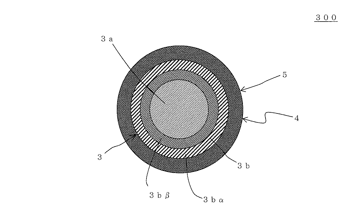
(実施例2〜33)
製造条件を表1、表2に示すように変化させた以外は、実施例1と同様にして排ガス浄化装置を作製した。実施例1の場合と同様にして、上記方法で、「圧力損失(圧損)」、「浄化性能」及び「耐久性」の評価を行った。結果を表3に示す。表1において、「触媒」の欄は、第2ハニカム触媒体の単位体積当たりの触媒量(g/リットル)を示す。表2において、「触媒」の欄は、ハニカム触媒体の単位体積当たりの触媒量(g/リットル)を示す。また、「発熱体」の「端子間抵抗」の欄は、通電用端子間の抵抗値を示す。
(Examples 2-33)
Exhaust gas purification apparatuses were produced in the same manner as in Example 1 except that the production conditions were changed as shown in Tables 1 and 2. In the same manner as in Example 1, “pressure loss (pressure loss)”, “purification performance”, and “durability” were evaluated by the above method. The results are shown in Table 3. In Table 1, the “catalyst” column indicates the amount of catalyst (g / liter) per unit volume of the second honeycomb catalyst body. In Table 2, the “catalyst” column indicates the catalyst amount (g / liter) per unit volume of the honeycomb catalyst body. Further, the column of “resistance between terminals” of “heating element” indicates a resistance value between terminals for energization.
また、熱容量は、レーザーフラッシュ法により測定した。熱伝導率は、レーザーフラッシュ法により測定した。体積抵抗率は、四端子法により測定した。 The heat capacity was measured by a laser flash method. The thermal conductivity was measured by a laser flash method. Volume resistivity was measured by the four probe method.
(比較例1)
実施例1における第2ハニカム触媒体のみを缶体内に収納して排ガス浄化装置を作製した(比較例1)。第2ハニカム触媒体は、熱容量が1200J/(m3・K)であり、熱伝導率は1W/(m・K)であり、体積抵抗率が1013Ωcmであった。実施例1の場合と同様にして、上記方法で、「圧力損失(圧損)」、「浄化性能」及び「耐久性」の評価を行った。結果を表3に示す。
(Comparative Example 1)
Only the second honeycomb catalyst body in Example 1 was housed in the can body to produce an exhaust gas purification device (Comparative Example 1). The second honeycomb catalyst body had a heat capacity of 1200 J / (m 3 · K), a thermal conductivity of 1 W / (m · K), and a volume resistivity of 10 13 Ωcm. In the same manner as in Example 1, “pressure loss (pressure loss)”, “purification performance”, and “durability” were evaluated by the above method. The results are shown in Table 3.
表1〜3より、実施例1〜33の排ガス浄化装置は、ハニカム触媒体のハニカム基材が、発熱部に発熱体を有することにより浄化性能に優れることが分かる。 From Tables 1 to 3, it can be seen that the exhaust gas purification apparatuses of Examples 1 to 33 have excellent purification performance when the honeycomb base material of the honeycomb catalyst body has the heating element in the heating portion.
本発明のハニカム触媒体は、化学、電力、鉄鋼等の様々な分野において、内燃機関から排出される排ガスを浄化する触媒体として、好適に利用することができる。そして、本発明の排ガス浄化装置は、上記触媒体を搭載した排ガス浄化装置として好適に利用することができる。 The honeycomb catalyst body of the present invention can be suitably used as a catalyst body for purifying exhaust gas discharged from an internal combustion engine in various fields such as chemistry, electric power, and steel. And the exhaust gas purification apparatus of this invention can be utilized suitably as an exhaust gas purification apparatus carrying the said catalyst body.
1,21:隔壁、2,22:セル、3:ハニカム部、3a:中央部、3b:外周部、3bα,3bβ:外周層、4:発熱部、5:ハニカム基材、6:発熱体、7:通電用端子、11:一方の端面、12:他方の端面、21:隔壁、22:セル、23:外周壁、24:第2ハニカム触媒体、25:ハニカム基材、31:入口開口部、32:出口開口部、33:缶体、34:留め具、35:充填材、36:電源、40:圧力損失測定装置、42:差圧計、43:ブロワー、44:測定試料、100,200,300:ハニカム触媒体,500,600:排ガス浄化装置、G,G1:ガス、T1,T2:時間。 1, 2: 1 partition, 2, 22: cell, 3: honeycomb part, 3a: center part, 3b: outer peripheral part, 3bα, 3bβ: outer peripheral layer, 4: heat generating part, 5: honeycomb substrate, 6: heat generating element, 7: terminal for energization, 11: one end face, 12: the other end face, 21: partition wall, 22: cell, 23: outer peripheral wall, 24: second honeycomb catalyst body, 25: honeycomb substrate, 31: inlet opening 32: outlet opening, 33: can body, 34: fastener, 35: filler, 36: power supply, 40: pressure loss measuring device, 42: differential pressure gauge, 43: blower, 44: measurement sample, 100, 200 , 300: honeycomb catalyst body, 500, 600: exhaust gas purification device, G, G1: gas, T1, T2: time.
Claims (8)
前記発熱部内に配設され、通電により発熱可能な発熱体と、
前記ハニカム部の前記隔壁に担持された触媒とを備え、
前記ハニカム部と前記発熱部が焼結により接合されているハニカム触媒体。 Cylindrical honeycomb having a honeycomb part having partition walls for partitioning and forming a plurality of cells extending from one end face to the other end face as a fluid flow path, and a heat generating part arranged to surround the outer periphery of the honeycomb part A substrate;
A heating element disposed in the heating unit and capable of generating heat when energized;
A catalyst supported on the partition walls of the honeycomb part,
A honeycomb catalyst body in which the honeycomb portion and the heat generating portion are joined by sintering.
前記ハニカム部の前記隔壁に担持された触媒とを備え、
前記ハニカム部と前記発熱部が焼結により接合されているハニカム触媒体であり、
前記ハニカム基材の発熱部の熱伝導率及び熱容量が、前記ハニカム基材のハニカム部の熱伝導率及び熱容量より大きいハニカム触媒体。 A honeycomb part having partition walls that partition and form a plurality of cells extending from one end face to the other end face that serves as a fluid flow path, and a heating part that is disposed so as to surround the outer periphery of the honeycomb part and can generate heat when energized. A cylindrical honeycomb substrate having,
A catalyst supported on the partition walls of the honeycomb part,
A honeycomb catalyst body in which the honeycomb portion and the heat generating portion are joined by sintering ;
A honeycomb catalyst body in which the heat conductivity and heat capacity of the heat generating portion of the honeycomb base material are larger than the heat conductivity and heat capacity of the honeycomb portion of the honeycomb base material.
前記外周部の隔壁厚さが、前記中央部の隔壁厚さより厚い請求項1〜4のいずれかに記載のハニカム触媒体。 In the cross section perpendicular to the cell extending direction, the honeycomb part is composed of a central part and an outer peripheral part surrounding the central part,
The honeycomb catalyst body according to any one of claims 1 to 4 , wherein a partition wall thickness of the outer peripheral portion is thicker than a partition wall thickness of the central portion.
流体の流路となる一方の端面から他方の端面まで延びる複数のセルを区画形成する隔壁及び最外周に配設された外周壁を有する筒状のハニカム基材、並びに前記隔壁に担持された触媒を有する第2ハニカム触媒体と、
前記ハニカム触媒体及び前記第2ハニカム触媒体を内部に収納した、一方の端部に入口開口部を有し、他方の端部に出口開口部を有する筒状の缶体と、
前記ハニカム触媒体に通電するための電源とを備え、
前記第2ハニカム触媒体が前記缶体の入口開口部側に配置され、前記ハニカム触媒体が前記缶体の出口開口部側に配置されるとともに、前記第2ハニカム触媒体と前記ハニカム触媒体とが、前記缶体の入口開口部から流入したガスが前記第2ハニカム触媒体の前記セルを通過した後に前記ハニカム触媒体の前記セルを通過するように、直列に配置された排ガス浄化装置。 A honeycomb catalyst body according to any one of claims 1 to 6,
A partition for partitioning a plurality of cells extending from one end face to the other end face to be a fluid flow path, a cylindrical honeycomb substrate having an outer peripheral wall disposed on the outermost periphery, and a catalyst supported on the partition A second honeycomb catalyst body having
A cylindrical can body containing the honeycomb catalyst body and the second honeycomb catalyst body therein, having an inlet opening at one end and an outlet opening at the other end;
A power source for energizing the honeycomb catalyst body,
The second honeycomb catalyst body is disposed on the inlet opening side of the can body, the honeycomb catalyst body is disposed on the outlet opening side of the can body, and the second honeycomb catalyst body, the honeycomb catalyst body, However, the exhaust gas purification apparatus arranged in series so that the gas flowing in from the inlet opening of the can passes through the cells of the honeycomb catalyst body after passing through the cells of the second honeycomb catalyst body.
Priority Applications (1)
| Application Number | Priority Date | Filing Date | Title |
|---|---|---|---|
| JP2010064320A JP5599208B2 (en) | 2010-03-19 | 2010-03-19 | Honeycomb catalyst body and exhaust gas purification device |
Applications Claiming Priority (1)
| Application Number | Priority Date | Filing Date | Title |
|---|---|---|---|
| JP2010064320A JP5599208B2 (en) | 2010-03-19 | 2010-03-19 | Honeycomb catalyst body and exhaust gas purification device |
Publications (2)
| Publication Number | Publication Date |
|---|---|
| JP2011194323A JP2011194323A (en) | 2011-10-06 |
| JP5599208B2 true JP5599208B2 (en) | 2014-10-01 |
Family
ID=44873200
Family Applications (1)
| Application Number | Title | Priority Date | Filing Date |
|---|---|---|---|
| JP2010064320A Active JP5599208B2 (en) | 2010-03-19 | 2010-03-19 | Honeycomb catalyst body and exhaust gas purification device |
Country Status (1)
| Country | Link |
|---|---|
| JP (1) | JP5599208B2 (en) |
Families Citing this family (9)
| Publication number | Priority date | Publication date | Assignee | Title |
|---|---|---|---|---|
| JP5796559B2 (en) | 2012-09-20 | 2015-10-21 | トヨタ自動車株式会社 | Electrode film and electrode terminal |
| JP2015074993A (en) * | 2013-10-07 | 2015-04-20 | 株式会社豊田自動織機 | Exhaust emission control device |
| JP6373696B2 (en) * | 2014-09-19 | 2018-08-15 | 日本碍子株式会社 | Thermal / sonic conversion parts and thermal / sonic conversion units |
| DE112016005249B4 (en) * | 2015-11-16 | 2023-09-28 | Ngk Insulators, Ltd. | Honeycomb type heating device and method of using the same |
| JP2016196887A (en) * | 2016-06-21 | 2016-11-24 | 日本碍子株式会社 | Fluid heating component |
| CN114302764B (en) * | 2019-09-11 | 2023-12-26 | 日本碍子株式会社 | Honeycomb structure and exhaust gas purification device |
| WO2021115950A1 (en) * | 2019-12-09 | 2021-06-17 | Vitesco Technologies GmbH | Apparatus for exhaust gas aftertreatment having an annular heated disc |
| JP7502920B2 (en) * | 2020-07-28 | 2024-06-19 | 株式会社キャタラー | Honeycomb Substrate Holder |
| JP6986123B1 (en) | 2020-08-07 | 2021-12-22 | 株式会社キャタラー | Exhaust gas purification catalyst |
Family Cites Families (7)
| Publication number | Priority date | Publication date | Assignee | Title |
|---|---|---|---|---|
| JPH0294316U (en) * | 1989-01-17 | 1990-07-26 | ||
| JP2928540B2 (en) * | 1989-06-19 | 1999-08-03 | イビデン株式会社 | Exhaust gas purification device |
| JPH05340235A (en) * | 1992-06-11 | 1993-12-21 | Matsushita Electric Ind Co Ltd | Exhaust emission control device for internal combustion engine |
| JPH07189667A (en) * | 1993-12-28 | 1995-07-28 | Shimadzu Corp | Induction heating type catalytic converter for automobiles |
| JPH07185264A (en) * | 1993-12-28 | 1995-07-25 | Sharp Corp | Honeycomb heater |
| JP3126697B2 (en) * | 1998-03-31 | 2001-01-22 | 日本碍子株式会社 | High strength thin-walled honeycomb structure |
| JP5134377B2 (en) * | 2006-02-10 | 2013-01-30 | 日本碍子株式会社 | Honeycomb segment and honeycomb structure |
-
2010
- 2010-03-19 JP JP2010064320A patent/JP5599208B2/en active Active
Also Published As
| Publication number | Publication date |
|---|---|
| JP2011194323A (en) | 2011-10-06 |
Similar Documents
| Publication | Publication Date | Title |
|---|---|---|
| JP5599208B2 (en) | Honeycomb catalyst body and exhaust gas purification device | |
| JP5261256B2 (en) | Energized heat generating honeycomb body and manufacturing method thereof | |
| JP3997825B2 (en) | Ceramic filter and ceramic filter with catalyst | |
| JP5261257B2 (en) | Control system for electrically heated honeycomb body | |
| US8530030B2 (en) | Honeycomb structure | |
| US20130036719A1 (en) | Honeycomb structure | |
| US9487448B2 (en) | Honeycomb structure | |
| US11092052B2 (en) | Electric heating type support, exhaust gas purifying device, and method for producing electric heating type support | |
| CN111706419A (en) | Electric heating type carrier and exhaust gas purification device | |
| CN112627944B (en) | Electric heating type carrier and exhaust gas purification device | |
| JP7335836B2 (en) | Electrically heated carrier, exhaust gas purifier, and method for producing electrically heated carrier | |
| JP5486973B2 (en) | Honeycomb catalyst body and exhaust gas purification device | |
| JP2018130668A (en) | Honeycomb structure | |
| CN115151715A (en) | Electric heating converter and electric heating carrier | |
| JP5193922B2 (en) | Exhaust gas purification treatment equipment | |
| JP5710323B2 (en) | Honeycomb structure and exhaust gas purification device | |
| US11725557B2 (en) | Electric heating type carrier and exhaust gas purification device | |
| JP5604047B2 (en) | Honeycomb structure | |
| US12577898B2 (en) | Honeycomb structure, electrically heated carrier, and exhaust gas purification device | |
| JP2006110413A (en) | Honeycomb filter | |
| JP6013243B2 (en) | Honeycomb catalyst body | |
| JP2015178445A (en) | honeycomb structure | |
| US20240167411A1 (en) | Electrically heating catalytic converter | |
| US20230311110A1 (en) | Honeycomb structure, electrically heated carrier and exhaust gas purification device | |
| JP7750761B2 (en) | Electrically heated carrier and exhaust gas purification device |
Legal Events
| Date | Code | Title | Description |
|---|---|---|---|
| A621 | Written request for application examination |
Free format text: JAPANESE INTERMEDIATE CODE: A621 Effective date: 20111124 |
|
| A977 | Report on retrieval |
Free format text: JAPANESE INTERMEDIATE CODE: A971007 Effective date: 20130212 |
|
| A131 | Notification of reasons for refusal |
Free format text: JAPANESE INTERMEDIATE CODE: A131 Effective date: 20130226 |
|
| A521 | Request for written amendment filed |
Free format text: JAPANESE INTERMEDIATE CODE: A523 Effective date: 20130424 |
|
| A131 | Notification of reasons for refusal |
Free format text: JAPANESE INTERMEDIATE CODE: A131 Effective date: 20140121 |
|
| A521 | Request for written amendment filed |
Free format text: JAPANESE INTERMEDIATE CODE: A523 Effective date: 20140306 |
|
| TRDD | Decision of grant or rejection written | ||
| A01 | Written decision to grant a patent or to grant a registration (utility model) |
Free format text: JAPANESE INTERMEDIATE CODE: A01 Effective date: 20140805 |
|
| A61 | First payment of annual fees (during grant procedure) |
Free format text: JAPANESE INTERMEDIATE CODE: A61 Effective date: 20140812 |
|
| R150 | Certificate of patent or registration of utility model |
Ref document number: 5599208 Country of ref document: JP Free format text: JAPANESE INTERMEDIATE CODE: R150 |