JP5596485B2 - child seat - Google Patents
child seat Download PDFInfo
- Publication number
- JP5596485B2 JP5596485B2 JP2010226535A JP2010226535A JP5596485B2 JP 5596485 B2 JP5596485 B2 JP 5596485B2 JP 2010226535 A JP2010226535 A JP 2010226535A JP 2010226535 A JP2010226535 A JP 2010226535A JP 5596485 B2 JP5596485 B2 JP 5596485B2
- Authority
- JP
- Japan
- Prior art keywords
- leg
- base
- support
- child seat
- support portion
- Prior art date
- Legal status (The legal status is an assumption and is not a legal conclusion. Google has not performed a legal analysis and makes no representation as to the accuracy of the status listed.)
- Expired - Fee Related
Links
Images


Classifications
-
- B—PERFORMING OPERATIONS; TRANSPORTING
- B60—VEHICLES IN GENERAL
- B60N—SEATS SPECIALLY ADAPTED FOR VEHICLES; VEHICLE PASSENGER ACCOMMODATION NOT OTHERWISE PROVIDED FOR
- B60N2/00—Seats specially adapted for vehicles; Arrangement or mounting of seats in vehicles
- B60N2/24—Seats specially adapted for vehicles; Arrangement or mounting of seats in vehicles for particular purposes or particular vehicles
- B60N2/26—Seats specially adapted for vehicles; Arrangement or mounting of seats in vehicles for particular purposes or particular vehicles for children
- B60N2/28—Seats readily mountable on, and dismountable from, existing seats or other parts of the vehicle
- B60N2/2857—Seats readily mountable on, and dismountable from, existing seats or other parts of the vehicle characterised by the peculiar orientation of the child
- B60N2/286—Seats readily mountable on, and dismountable from, existing seats or other parts of the vehicle characterised by the peculiar orientation of the child forward facing
-
- B—PERFORMING OPERATIONS; TRANSPORTING
- B60—VEHICLES IN GENERAL
- B60N—SEATS SPECIALLY ADAPTED FOR VEHICLES; VEHICLE PASSENGER ACCOMMODATION NOT OTHERWISE PROVIDED FOR
- B60N2/00—Seats specially adapted for vehicles; Arrangement or mounting of seats in vehicles
- B60N2/24—Seats specially adapted for vehicles; Arrangement or mounting of seats in vehicles for particular purposes or particular vehicles
- B60N2/26—Seats specially adapted for vehicles; Arrangement or mounting of seats in vehicles for particular purposes or particular vehicles for children
-
- B—PERFORMING OPERATIONS; TRANSPORTING
- B60—VEHICLES IN GENERAL
- B60N—SEATS SPECIALLY ADAPTED FOR VEHICLES; VEHICLE PASSENGER ACCOMMODATION NOT OTHERWISE PROVIDED FOR
- B60N2/00—Seats specially adapted for vehicles; Arrangement or mounting of seats in vehicles
- B60N2/02—Seats specially adapted for vehicles; Arrangement or mounting of seats in vehicles the seat or part thereof being movable, e.g. adjustable
- B60N2/20—Seats specially adapted for vehicles; Arrangement or mounting of seats in vehicles the seat or part thereof being movable, e.g. adjustable the back-rest being tiltable, e.g. to permit easy access
-
- B—PERFORMING OPERATIONS; TRANSPORTING
- B60—VEHICLES IN GENERAL
- B60N—SEATS SPECIALLY ADAPTED FOR VEHICLES; VEHICLE PASSENGER ACCOMMODATION NOT OTHERWISE PROVIDED FOR
- B60N2/00—Seats specially adapted for vehicles; Arrangement or mounting of seats in vehicles
- B60N2/24—Seats specially adapted for vehicles; Arrangement or mounting of seats in vehicles for particular purposes or particular vehicles
- B60N2/26—Seats specially adapted for vehicles; Arrangement or mounting of seats in vehicles for particular purposes or particular vehicles for children
- B60N2/28—Seats readily mountable on, and dismountable from, existing seats or other parts of the vehicle
- B60N2/2821—Seats readily mountable on, and dismountable from, existing seats or other parts of the vehicle having a seat and a base part
- B60N2/2824—Seats readily mountable on, and dismountable from, existing seats or other parts of the vehicle having a seat and a base part part of the base being supported by the vehicle frame
-
- B—PERFORMING OPERATIONS; TRANSPORTING
- B60—VEHICLES IN GENERAL
- B60N—SEATS SPECIALLY ADAPTED FOR VEHICLES; VEHICLE PASSENGER ACCOMMODATION NOT OTHERWISE PROVIDED FOR
- B60N2/00—Seats specially adapted for vehicles; Arrangement or mounting of seats in vehicles
- B60N2/24—Seats specially adapted for vehicles; Arrangement or mounting of seats in vehicles for particular purposes or particular vehicles
- B60N2/26—Seats specially adapted for vehicles; Arrangement or mounting of seats in vehicles for particular purposes or particular vehicles for children
- B60N2/28—Seats readily mountable on, and dismountable from, existing seats or other parts of the vehicle
- B60N2/2821—Seats readily mountable on, and dismountable from, existing seats or other parts of the vehicle having a seat and a base part
- B60N2/2827—Seats readily mountable on, and dismountable from, existing seats or other parts of the vehicle having a seat and a base part part of the base being supported by the seat sub-frame
Description
本発明はチャイルドシートに係り、ベースの前端にサポートレッグが装備され、サポートレッグを車両フロア上に起立させて、衝突時におけるチャイルドシートの前方への回動を防止し、乳幼児の身体を安全に拘束するようにしたチャイルドシートに関する。 The present invention relates to a child seat, and a support leg is provided at the front end of the base. The support leg is erected on the vehicle floor to prevent the child seat from pivoting forward in the event of a collision and to restrain the infant's body safely. It relates to the child seat.
チャイルドシートには、座面に密着した比較的大型のベース上に、リクライニング機構を介して本体シェルを保持するタイプがある。この種のチャイルドシートでは、ベースの前端にサポートレッグが設けられ、座席上に固定された状態でこのサポートレッグを、車両フロア上に起立させることで、前面衝突時等におけるチャイルドシートの前方への回動を防止し、チャイルドシートの安全性の向上を図ることができる。 There is a type of child seat in which a main body shell is held via a reclining mechanism on a relatively large base that is in close contact with a seating surface. In this type of child seat, a support leg is provided at the front end of the base, and the support leg is raised on the vehicle floor in a state of being fixed on the seat, so that the child seat can be rotated forward in a frontal collision or the like. Can be prevented, and the safety of the child seat can be improved.
この種のサポートレッグを備えたチャイルドシートには、下端部が車体フロアに支持された長尺状の支持脚部と、車両前後方向を長手方向として配置されるとともに後端部がチャイルドシートの下端部側に連結され、さらに前端部が支持脚部の上端部に折り畳み可能に連結された長尺状の支持アームとを備えたチャイルドシート支持装置がある(特許文献1)。 The child seat with this type of support leg has an elongated support leg whose lower end is supported by the vehicle body floor, and the vehicle front-rear direction is the longitudinal direction and the rear end is the lower end side of the child seat. There is also a child seat support device including an elongate support arm that is connected to the upper end portion of the support leg portion so as to be foldable (Patent Document 1).
このチャイルドシート支持装置によれば、車両急減速時等にチャイルドシートに着座した子供に作用する慣性力によって、チャイルドシートが車両シートへの拘束点(シートベルト装置による固定点)回りに前傾しようとするのを、車両側方から見て差し金状をなした前記支持脚部と支持アームとでチャイルドシートの前端を支持するようになっている。たとえば、車両急減速時等とにチャイルドシートに作用した荷重は支持アームから支持脚部に伝わり、最終的に車両フロアによって支持される。これによりチャイルドシートが前傾して車両シートのシートクッションに沈み込むのが防止される。 According to this child seat support device, the child seat tends to tilt forward around the restraint point (fixed point by the seat belt device) to the vehicle seat by the inertial force acting on the child seated on the child seat at the time of sudden deceleration of the vehicle or the like. The front end of the child seat is supported by the support leg portion and the support arm which are formed in the form of a metal when viewed from the side of the vehicle. For example, the load acting on the child seat at the time of sudden deceleration of the vehicle is transmitted from the support arm to the support leg, and is finally supported by the vehicle floor. This prevents the child seat from tilting forward and sinking into the seat cushion of the vehicle seat.
ところで、特許文献1に開示されたチャイルドシート支持装置の支持脚部と支持アームの断面形状はともに薄い平板をなし、支持アームはベース座部の前端から所定長さだけ張り出した状態で支持脚部の上端部と折り畳み可能に連結されている。これに対して車両急減速時あるいは前面衝突時等に幼児が着座しているチャイルドシートに作用する慣性力は、相当に大きいため、薄い板状の部材をL字形状(差し金状)に連結した部材では、その慣性力を支えきれない。そのため、金属パイプを曲げ加工し水平部材と回動部を介して連結された比較的剛性の高い脚部でベース前面を支持するようにしたチャイルドシートのサポートレッグ装置も開発されている(特許文献2参照)。
By the way, the cross-sectional shapes of the support leg and the support arm of the child seat support device disclosed in
特許文献2に開示された、脚長を伸縮可能なパイプ製のサポートレッグは、チャイルドシートのベースの下面側に折り畳み収納されるようになっている。このため、折り畳まれたサポートレッグを起立させるには、ベースを横向きにして倒して動かないように保持した状態で、片手でサポートレッグの回転部に設けられたロック機構を解除しながら、他方の手でサポートレッグを起立させる必要があり、チャイルドシートを保持しながら、これら一連の作業をスムースに行うのは困難であった。
The pipe-made support leg disclosed in
また、特許文献2でもサポートレッグの長さ調整機構が提案されているが、パイプに所定間隔で空けられた孔にストッパとしての調整ピンを挿入するだけであるため、2重構造となったパイプ間に隙間が生じ、ガタつきがあり、使用時に異音が発生するという問題もある。そこで、本発明の目的は上述した従来の技術が有する問題点を解消し、不使用時には折り畳み収容が容易で、使用時に簡単にサポートレッグを起こすことができ、またサポートレッグの長さを容易に調整できる機構を組み込んだサポートレッグを備えたチャイルドシートを提供することにある。
Also,
上記目的を達成するために、本発明は幼児を拘束して着座させる本体を支持するベース内に収容され、該ベースを補剛するとともに、前端部が前記ベースに形成された切欠部から露出するように前記ベース内に配置固定され、前記ベースの前端に位置する前端フレームと、該前端フレームの両側に連続し、前記ベースの長手方向に延在する補剛フレームとからなる略U字形に加工されたパイプ材からなり、前記前端フレームに回動支持部が回動可能に取り付けられたフレーム体と、該フレーム体に前記前端フレームを軸部として回動可能に取り付けられ、内部に収容された付勢手段により付勢されたロックピンが、前記前端フレームに形成された貫通孔に挿通されて、その回動がロックされ、前記回動支持部から、前記付勢手段に抗して所定量引き出すことで、前記ロックが解除されるロック機構が収容された前記回動支持部に連結された脚部を所定長さに調整保持可能な脚支持部を有するサポートレッグとを備え、前記ベースを車両シート上に固定するとともに、前記サポートレッグを前記回動支持部回りに回動させて前記ベース前端位置で所定脚長に調整し、車体フロアに前記脚支持部の底板を当接させて前記ベースを安定保持させたことを特徴とする。 In order to achieve the above object, the present invention is accommodated in a base that supports a main body that restrains and seats an infant, stiffens the base, and a front end portion is exposed from a notch formed in the base. And is processed into a substantially U-shape comprising a front end frame positioned at the front end of the base and a stiffening frame extending on both sides of the front end frame and extending in the longitudinal direction of the base. And a frame body that is pivotally attached to the front end frame, and is pivotally attached to the frame body with the front end frame as a shaft, and housed inside. The lock pin urged by the urging means is inserted into a through hole formed in the front end frame, and its rotation is locked. From the rotation support portion, the lock pin is opposed to the urging means. By pulling out, and a support leg having a lock adjustable holding leg that is connected to the pivot support portion where the lock mechanism is accommodated to be released in a predetermined length of leg support, said base The base is fixed on the vehicle seat, and the support leg is rotated around the rotation support portion to be adjusted to a predetermined leg length at the base front end position, and the base plate of the leg support portion is brought into contact with the vehicle body floor. Is characterized by being stably held.
前記サポートレッグの脚部を引き出した状態で、前記脚支持部の一部を収容可能な凹所が前記ベース底面に形成されることが好ましい。 It is preferable that a recess capable of accommodating a part of the leg support portion is formed on the bottom surface of the base in a state where the leg portion of the support leg is pulled out.
前記脚支持部は、前記脚部がスライド可能に挿入される脚保持孔を有し、前記脚部が所定長さに保持された状態で、前記脚部を前記脚保持孔の内側面に押圧する付勢押圧部材を有することが好ましい。 The leg support part has a leg holding hole into which the leg part is slidably inserted, and the leg part is pressed against the inner surface of the leg holding hole in a state where the leg part is held at a predetermined length. It is preferable to have an urging pressing member.
本発明によれば、チャイルドシートのベースに取り付けられたサポートレッグの折り畳み動作、起立動作を片手で容易に行えるとともに、サポートレッグの長さを車体フロアに合わせて容易に調整することができるという効果を奏する。 According to the present invention, the support leg attached to the child seat base can be easily folded and raised with one hand, and the length of the support leg can be easily adjusted according to the vehicle body floor. Play.
以下、本発明のチャイルドシートの好ましい実施形態として、以下の実施例について添付図面を参照して説明する。 Hereinafter, the following examples will be described with reference to the accompanying drawings as preferred embodiments of the child seat of the present invention.
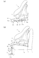
図1は、本発明のチャイルドシート1を車両の座席に前向きに取り付けた状態を示した斜視図である。本実施例では、このチャイルドシート1は、ベース10と本体シェル2とからなる構造で、本体シェル2を支持するベース10がISOFIX規格によるアンカー機構3によって車両シート4に固定された状態を想定している。同図では、ベース前端10aの下面側に回動支持部20を介して取り付けられたサポートレッグ30を、車両シート4の前方のフロア5上に起立させて、ベース10を支持した状態が示されている。なお、本実施例では、本体シェル2とベース10とは公知の着脱機構(図示せず)によって一体化が図られている。
FIG. 1 is a perspective view showing a state in which a
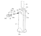
ベース前端10aに取り付けられたサポートレッグ30は、図示したように、合成樹脂製の脚支持部31を有し、円板状をなした底板31aで車体フロア5面に安定して起立している。脚支持部31の前面上部にはボタンアジャスタ32(後述する)のプッシュボタン32aが突出している。このプッシュボタン32aは、サポートレッグ30の脚支持部31内に収容された金属製のレッグパイプの長さ調整および固定位置のロック機構のセットおよび解除機能を果たすワンタッチボタンである。構成の詳細は図6、図7を参照して後述する。
As shown in the figure, the
チャイルドシート1をシート4上に固定して、サポートレッグ30をフロア5上に起立させることにより、チャイルドシート1の設置時の安定度が増し、たとえば幼児がチャイルドシートに着座した状態で、車両が急減速した場合に、チャイルドシートの重量と幼児の体重を含めた重量の慣性力がチャイルドシート1に作用しても、チャイルドシート1が前方に回動するのを確実に防止でき、着座した幼児の安全を図ることができる。
By fixing the
図2(a)は、図1に示したチャイルドシート1のみを示した側面図である。同図に示したように、チャイルドシート1のみの場合には、サポートレッグ30はベース前端10aの回動支持部20でベース底面10b側に折り畳まれ、ベース底面10bの一部に収容されるようになっている。このとき、合成樹脂製のベース10の底面10bには、脚支持部31の背面部の一部を収容可能な凹所11(図5(c)参照)が形成されており、その凹所11に脚支持部31の背面側が収容される。このとき脚支持部31の前面側は図示したように、ベース底面10bから突出するような状態にある。このように、脚支持部31の前面がベース底面10bから突出した状態では、チャイルドシート1のベース10を図2(b)に示した状態のように、車両シート4上に密着して設置できないので、ユーザーは必ずサポートレッグ30を、起立させて車体フロア5上に支持させて使用することになり、サポートレッグ30の利用率を高めるという副次的な効果もある。
FIG. 2A is a side view showing only the
図2(b)は、図1と同じ状態の側面図である。同図に示したように、ベース10の前端10aは車両シート4前端から突出した部分が下方にわずかに屈曲し、その前端部位にサポートレッグ30の上端が回動支持部20を介して連結されている。ベース10をこのような形状にすることにより、着座した幼児の足下の空間を広く確保することができる。
FIG. 2B is a side view of the same state as FIG. As shown in the figure, the
図3は、チャイルドシート1の本体シェル2を外した状態のベース10内を説明するために、ベース上面10cの一部を切欠いて示した斜視図である。同図に示したように、ベース10内には、平面視して略U字形に加工された金属製パイプからなるメインフレーム12がベース10の長手方向(前後方向)に沿って図示しない固定ねじおよびベース10の一部に成形されたフレーム保持部13により固定されている。さらに、このメインフレーム12の前端フレーム12aにはサポートレッグ30の回動支持部20が取り付けられている。この回動支持部20は、内部にサポートレッグ30の起立時のロックおよびロック状態を解除するロック機構(構成は後述する。)を備えている。
FIG. 3 is a perspective view in which a part of the base
このようにメインフレーム12は、前端フレーム12aとその両側に連続し、ベース10の長手方向に延在する補剛フレーム12bとを一体的に曲げ加工したパイプからなるため、メインフレーム12がベース10内部全体に保持固定されることで、ベース10全体の剛性が確保でき、サポートレッグ30を介してのチャイルドシート1全体の前方への回動防止が確実に図られる。さらにベース前端10aの切欠かれた部位にサポートレッグ30の回動支持部20が取り付けられることにより、ベース前端10aに突出する部位が生じないので、着座した幼児が突出した部位に足をぶつけたりすることを回避できる。
Thus, the
ここで、サポートレッグ30がメインフレーム12の前端フレーム12aに連結される回動支持部20の構成について、図4及び図5(a)を参照して説明する。
図5(a)は脚支持部31で保持されたレッグパイプ33の上端に設けられた回動支持部20の構成を断面で示している。この部位の各構成部品およびその関係について、図4の分解斜視図を用いて説明する。
図4に示したように、回動支持部20は、各構成部品が、上下に分割された樹脂成形部材からなるアッパーカバー21とロアカバー22内に収容されている。ロアカバー22は脚支持部31に保持されたレッグパイプ33が挿通されるガイドパイプ22aとガイドパイプ22aの上部の回動部材収容部22bとを一体成形した樹脂成形品で、その内部には、レッグパイプ33に外嵌されるロックスプリング23と、レッグパイプ33の上端に軸部24aが挿入されるパイプエンドホルダ24が収容される。このパイプエンドホルダ24の軸部24aが、固定ピン25によりレッグパイプ33上端に固定されるとともに、パイプエンドホルダ24に形成されたピン収容穴24cにロックピン26が下方から挿入され、ロックピン26は下端フランジ26aと固定ピン25でとでパイプエンドホルダ24保持される。
Here, the structure of the
FIG. 5A shows in cross section the structure of the
As shown in FIG. 4, each component of the
パイプエンドホルダ24はレッグパイプ33に挿入固定される軸部24aとフレーム保持プレート支持部24bとが一体成形された樹脂成形品である。フレーム保持プレート27はメインフレーム12に密着可能な内径部を有する半円筒形状に曲げ加工され両端に接合フランジ27bが形成された金属加工板で、図4に示したように、同形の半円筒形状の上側プレート27Uと下側プレート27Lとを対向させてメインフレーム12の前端フレーム12aを把持して保持するようになっている。さらに半円筒形状部分の中央位置にはロックピン26がスライド可能に貫通するロックピン保持孔27aが形成されている。このロックピン保持孔27aは、外面に向けてカーリング加工され、このロックピン保持孔27aをスライドするロックピン26をガイドし、かつ位置保持しやすくなっている。
The
上述した各部品は、ロアカバー22内及びレッグパイプ33に装着され、全体を覆うように上方からアッパーカバー21が被され、アッパーカバー21とロアカバー22とを接合ボルト28で連結することで、回動支持部20が構成されている。
Each of the above-described components is mounted in the
以下、サポートレッグ30の起立状態および、回動支持部20での折り畳み時の動作について、図5各図を参照して説明する。図5(a)はサポートレッグ30を起立させた状態を示している。この起立状態では、回動支持部20内に収容されたロックスプリング23の付勢力によりパイプエンドホルダ24は下側プレート27Lの下面に押圧された状態にある。このときパイプエンドホルダ24に保持されたロックピン26は前端フレーム12aに形成された貫通孔14(図4参照)を貫通し、さらに上端が上側プレート27Uのロックピン保持孔27aを貫通し、アッパーカバー21に形成された凹所21a内に突出した状態にある。したがって、レッグパイプ33と一体化したロックピン26がメインフレーム12の貫通孔14を貫通した状態で堅固にロックされているため、図5(a)に示した起立状態が確実に保持される。
Hereinafter, the standing state of the
車両シート4からとりはずしたチャイルドシート1のサポートレッグ30を折り畳むためには、図5(b)に示したように、脚支持部31を持って、サポートレッグ30内のロックスプリング23のバネ力に抗してレッグパイプ33を引き出す。具体的にはロックスプリング23が完全に圧縮状態になるだけの長さLだけレッグパイプ33を引っ張ると、パイプエンドホルダ24と一体化しているロックピン26がメインフレーム12の貫通孔14(図4参照)から引き抜かれた状態になる。この状態でメインフレーム12とレッグパイプ33とのロックが解除され、ロックピン26の先端は下側プレート27Lのカーリング加工部に保持されて前端フレーム12aの外周面に当接した状態で、サポートレッグ30を図示した折り畳み方向(X方向)に折り畳むように回動させることができる。
In order to fold the
この状態でサポートレッグ30をチャイルドシート1のベース底面10bまで回動させ、図5(c)に示したように、ベース底面10bに形成された凹所11に脚支持部31を嵌め込むことでサポートレッグ30をベース底面10b側に収容することができる。
In this state, the
一方、サポートレッグ30を起立させるには、ベース底面10bの凹所11に嵌め込まれた脚支持部31を凹所11から引き出し、そのまま起立方向に回動させると、図5(a)に示した角度になるとロックスプリング23に付勢されたロックピン26が前端フレーム12aの貫通孔14に挿入され、さらに先端が上側プレート27Uの孔27aから突出し、サポートレッグ30の起立状態が保持される。
On the other hand, in order to erect the
このように、サポートレッグ30を折り畳む場合には、脚支持部31を持ってレッグパイプ33を所定量だけ引き出して回動するだけでサポートレッグ30を折り畳むことができる。一方、サポートレッグ30を起立させるには、ベース底面10bの凹所11から脚支持部31を引き起こして起立状態まで回動すればロックピン26の作用により自動的にロック状態となる。このように片方の手でチャイルドシートの本体を支えつつ、他方の手でサポートレッグ30の脚支持部31を引っ張りながら回動させるだけで、サポートレッグ30を容易に折り畳め、また収納状態から脚支持部31を引き出して立てるように回動させるだけで、サポートレッグ30を起立状態にすることもできる。
Thus, when the
[サポートレッグの脚支持部の長さ調整機構]
以下、サポートレッグ30の脚支持部31に組み込まれたレッグパイプ33の長さ調整機構の構成について、図6,図7各図を参照して説明する。
サポートレッグ30の脚支持部31は上述したように、レッグパイプ33の下半部を収容保持し、円板状の底板31aがフロア5に当接し、サポートレッグ30を確実に支持させる合成樹脂成形部材からなる。この脚支持部31の上端部には、内部に図6に示したストッパピン36と付勢スプリング35とを収容可能な突起部34と、脚部本体内にボタンアジャスタ32とを収容可能な収容空間34aとが形成されている(図7(a)参照。)一方、レッグパイプ33の外周面の所定位置には適正な範囲にわたり、高さ方向に所定間隔をあけて高さ保持孔33aが形成されている(図7参照)。
[Length adjustment mechanism of support leg leg support]
Hereinafter, the configuration of the length adjusting mechanism of the
As described above, the
ボタンアジャスタ32は、図6に示したように、レッグパイプ33の直径とプッシュボタン32aの押し込みしろとを足した長さにほぼ等しい長辺Sを有する平面視して略D字形をなす、付勢押圧部材として機能するリング状体32bと、付勢スプリング35の付勢に抗して動作させるプッシュボタン32aとからなる。ストッパピン36は付勢スプリング35の内径より細い軸部と付勢スプリング35の一端を保持するカラー36aを有し、ボタンアジャスタ32の操作により、先端36bが高さ保持孔33aに挿通され、レッグパイプ33の位置決めを行えるようになっている。
As shown in FIG. 6, the
これらの部品の組立手順としては、図6に示したように、突起部34の収容空間34a内に付勢スプリング35を収容し、スプリング内径より細いストッパピン36を付勢スプリング35内に挿入し、ストッパピン36のカラー36aとの間に付勢スプリング35を位置させる。付勢スプリング35とストッパピン36とを収容した後に、ボタンアジャスタ32を側面開口31dからプッシュボタン32aが正面側を向くように挿入し、その後、上方からレッグパイプ33を脚保持孔31b内に挿通する。
As shown in FIG. 6, assembling procedures of these parts, the urging
図7(a)は、レッグパイプ33の固定時を示した断面図である。同図に示したように、脚支持部31の突起部34の収容空間34a内に収容された付勢スプリング35の付勢力によりストッパピン36の先端36bがレッグパイプ33の高さ保持孔33aに挿入され、レッグパイプ33の高さが規定されるとともに、ストッパピン36のカラー36aがボタンアジャスタ32のリング状体32bをレッグパイプ33側に押圧し、レッグパイプ33を脚支持部31の脚保持孔31b内の一方に押圧する。これによりレッグパイプ33は長手方向にわたり脚保持孔31b内で一方向に押圧される。このため、レッグパイプ33と脚保持孔31bとの間にあったクリアランス(遊び)によるレッグパイプ33のガタつきが解消される。
FIG. 7A is a cross-sectional view showing when the
図7(a)のレッグパイプ33固定状態からレッグパイプ33の高さ調整を行うためには、図7(b)に示したように、ボタンアジャスタ32のプッシュボタン32aを押してストッパピン36の先端36bをレッグパイプ33の高さ保持孔33aから押し抜けばよい。これによりレッグパイプ33は高さ方向に自由にスライドできる。脚支持部31の底板31aが車体フロア5に当接できる高さにレッグパイプ33を調節し、別の高さ保持孔33aに合うと、ストッパピン36が作動してロック状態となるので、それを確認してサポートレッグ30をセットすればよい。
In order to adjust the height of the
以上の説明は、本体シェル2とベース10とが分離可能なタイプのチャイルドシート1を例に説明したが、本体シェルの底部にベース部分が一体化しているタイプのチャイルドシートにおいても、そのベースの前端に上述した回動支持部を介してサポートレッグを取り付けることで同様の効果を奏することができることはいうまでもない。
In the above description, the
すなわち、本発明は上述した実施例に限定されるものではなく、各請求項に示した範囲内での種々の変更が可能である。すなわち、請求項に示した範囲内で適宜変更した技術的手段を組み合わせた実施形態も、本発明の技術的範囲に含まれるものである。 That is, the present invention is not limited to the above-described embodiments, and various modifications can be made within the scope shown in each claim. That is, an embodiment in which technical means appropriately changed within the scope of the claims is also included in the technical scope of the present invention.
1 チャイルドシート
2 本体シェル
4 車両シート
5 車体フロア(フロア)
10 ベース
11 凹所
12 メインフレーム
12a 前端フレーム
14 貫通孔
20 回動支持部
23 ロックスプリング
24 パイプエンドホルダ
25 固定ピン
26 ロックピン
27 フレーム保持プレート
27L 下側プレート
27U 上側プレート
30 サポートレッグ
31 脚支持部
32 ボタンアジャスタ
32a プッシュボタン
33 レッグパイプ
34 突起部
35 付勢スプリング
36 ストッパピン
1
10
Claims (3)
該フレーム体に前記前端フレームを軸部として回動可能に取り付けられ、内部に収容された付勢手段により付勢されたロックピンが、前記前端フレームに形成された貫通孔に挿通されて、その回動がロックされ、前記回動支持部から、前記付勢手段に抗して所定量引き出すことで、前記ロックが解除されるロック機構が収容された前記回動支持部に連結された脚部を所定長さに調整保持可能な脚支持部を有するサポートレッグとを備え、
前記ベースを車両シート上に固定するとともに、前記サポートレッグを前記回動支持部回りに回動させて前記ベース前端位置で所定脚長に調整し、車体フロアに前記脚支持部の底板を当接させて前記ベースを安定保持させたことを特徴とするチャイルドシート。 Housed in the base for supporting the body to be seated by restraining the infant, as well as stiffening the base, the fixedly arranged in the base so that the front end portion exposed from the notch formed in the base, the A pipe material processed into a substantially U-shape comprising a front end frame located at the front end of the base and a stiffening frame extending on both sides of the front end frame and extending in the longitudinal direction of the base. A frame body on which the rotation support portion is rotatably attached ;
A lock pin that is pivotally attached to the frame body with the front end frame as a shaft portion and is urged by urging means housed therein is inserted into a through hole formed in the front end frame, and A leg portion connected to the rotation support portion in which a lock mechanism is housed in which the lock is unlocked and the lock mechanism is released by pulling a predetermined amount from the rotation support portion against the biasing means. And a support leg having a leg support portion that can be adjusted and held to a predetermined length,
The base is fixed on the vehicle seat, and the support leg is rotated around the rotation support portion to be adjusted to a predetermined leg length at the base front end position, and the bottom plate of the leg support portion is brought into contact with the vehicle body floor. A child seat characterized by stably holding the base.
Priority Applications (4)
| Application Number | Priority Date | Filing Date | Title |
|---|---|---|---|
| JP2010226535A JP5596485B2 (en) | 2010-10-06 | 2010-10-06 | child seat |
| CN201110305691.2A CN102442238B (en) | 2010-10-06 | 2011-09-29 | Child seat |
| EP11008064.5A EP2439102B1 (en) | 2010-10-06 | 2011-10-05 | Child seat |
| KR1020110101057A KR20120035880A (en) | 2010-10-06 | 2011-10-05 | Child seat |
Applications Claiming Priority (1)
| Application Number | Priority Date | Filing Date | Title |
|---|---|---|---|
| JP2010226535A JP5596485B2 (en) | 2010-10-06 | 2010-10-06 | child seat |
Publications (2)
| Publication Number | Publication Date |
|---|---|
| JP2012076717A JP2012076717A (en) | 2012-04-19 |
| JP5596485B2 true JP5596485B2 (en) | 2014-09-24 |
Family
ID=44862280
Family Applications (1)
| Application Number | Title | Priority Date | Filing Date |
|---|---|---|---|
| JP2010226535A Expired - Fee Related JP5596485B2 (en) | 2010-10-06 | 2010-10-06 | child seat |
Country Status (4)
| Country | Link |
|---|---|
| EP (1) | EP2439102B1 (en) |
| JP (1) | JP5596485B2 (en) |
| KR (1) | KR20120035880A (en) |
| CN (1) | CN102442238B (en) |
Families Citing this family (20)
| Publication number | Priority date | Publication date | Assignee | Title |
|---|---|---|---|---|
| CN102582479B (en) * | 2011-01-06 | 2014-11-05 | 明门香港股份有限公司 | Support device |
| CN202147605U (en) * | 2011-06-21 | 2012-02-22 | 宝鉅儿童用品香港股份有限公司 | Safe seat device |
| CN103465805B (en) | 2012-06-07 | 2016-02-03 | 宝钜儿童用品香港股份有限公司 | Child safety seat |
| JP6230872B2 (en) * | 2012-12-11 | 2017-11-15 | アップリカ・チルドレンズプロダクツ合同会社 | Infant container |
| CN104290618B (en) * | 2013-07-17 | 2017-03-01 | 明门香港股份有限公司 | Support feet guiding mechanism and support feet |
| JP6356503B2 (en) * | 2014-06-24 | 2018-07-11 | アップリカ・チルドレンズプロダクツ合同会社 | child seat |
| JP6420112B2 (en) * | 2014-10-14 | 2018-11-07 | 株式会社カーメイト | Child seat support device |
| CN105799559B (en) * | 2014-12-31 | 2018-04-13 | 明门香港股份有限公司 | Height regulating mechanism and the infant carrier device with this height regulating mechanism |
| CN104875636B (en) * | 2015-06-12 | 2017-04-12 | 上海翼锐汽车科技有限公司 | Light supporting leg of child seat |
| JP6590673B2 (en) * | 2015-12-10 | 2019-10-16 | アップリカ・チルドレンズプロダクツ合同会社 | child seat |
| KR101850833B1 (en) * | 2016-09-13 | 2018-05-31 | 주식회사 쁘레베베 | Support leg and safety car seat for infant using the same |
| CN107839554A (en) * | 2016-09-19 | 2018-03-27 | 珠海弘点科技有限公司 | Children's seat leg structure and children's seat support base |
| KR101698730B1 (en) * | 2016-11-01 | 2017-01-20 | 이명주 | Position adjusting device of footrest for car seat |
| US10272804B2 (en) * | 2016-11-08 | 2019-04-30 | Wonderland Switzerland Ag | Child safety seat |
| NO343527B1 (en) * | 2017-03-27 | 2019-04-01 | Torgersen Hans & Soenn | Child safety seat for a vehicle |
| JP6850197B2 (en) * | 2017-05-29 | 2021-03-31 | ニューウェルブランズ・ジャパン合同会社 | child seat |
| CN109305072B (en) * | 2017-07-26 | 2024-01-30 | 珠海阳光儿童用品有限公司 | Child safety seat support |
| CN110281821A (en) * | 2019-06-27 | 2019-09-27 | 宁波宝贝第一母婴用品有限公司 | A kind of child safety seat supporting leg locked automatically and its folding method |
| KR102224094B1 (en) * | 2019-10-28 | 2021-03-08 | 주식회사 서연이화 | Tether anchor assembly for child seat fixture |
| CN113212302B (en) * | 2021-04-20 | 2023-04-18 | 宁波环球娃娃婴童用品股份有限公司 | Installation adjustment detection method and system for child safety seat |
Family Cites Families (12)
| Publication number | Priority date | Publication date | Assignee | Title |
|---|---|---|---|---|
| JP2001107925A (en) * | 1999-10-12 | 2001-04-17 | Takano Co Ltd | Expansion mechanism and light vehicle using it |
| JP3429471B2 (en) | 2000-03-01 | 2003-07-22 | 株式会社東海理化電機製作所 | Child seat support device |
| US6817665B2 (en) * | 2001-07-26 | 2004-11-16 | Graco Children's Products Inc. | Seat base with load leg |
| JP4898037B2 (en) * | 2001-09-25 | 2012-03-14 | コンビ株式会社 | Child seat support leg device |
| US20080303321A1 (en) * | 2004-05-08 | 2008-12-11 | Britax Excelsior Limited | Base for a Child Safety Support |
| GB0420414D0 (en) * | 2004-09-14 | 2004-10-20 | Barker Derrick | Child car seat |
| NL1028788C2 (en) * | 2005-04-18 | 2006-10-20 | Maxi Miliaan Bv | Undercarriage as well as child vehicle seat provided with such an undercarriage. |
| GB0510313D0 (en) * | 2005-05-20 | 2005-06-29 | Britax Childcare Ltd | Child safety seat |
| EP1927502B1 (en) * | 2006-11-28 | 2009-09-09 | Wonderland Nurserygoods Co., Ltd. | Child vehicle safety seat |
| EP1970247A1 (en) * | 2007-03-15 | 2008-09-17 | Team-Tex | Device for mounting a child seat in a car and a child seat |
| JP2010226535A (en) | 2009-03-24 | 2010-10-07 | Fuji Xerox Co Ltd | Controller, image forming apparatus and program |
| CN201511847U (en) * | 2009-10-11 | 2010-06-23 | 林江娟 | Motor vehicle seat chair with ISOFIX joint for children |
-
2010
- 2010-10-06 JP JP2010226535A patent/JP5596485B2/en not_active Expired - Fee Related
-
2011
- 2011-09-29 CN CN201110305691.2A patent/CN102442238B/en not_active Expired - Fee Related
- 2011-10-05 EP EP11008064.5A patent/EP2439102B1/en active Active
- 2011-10-05 KR KR1020110101057A patent/KR20120035880A/en not_active Application Discontinuation
Also Published As
| Publication number | Publication date |
|---|---|
| EP2439102A2 (en) | 2012-04-11 |
| EP2439102B1 (en) | 2020-04-01 |
| EP2439102A3 (en) | 2017-11-29 |
| JP2012076717A (en) | 2012-04-19 |
| CN102442238B (en) | 2015-09-16 |
| KR20120035880A (en) | 2012-04-16 |
| CN102442238A (en) | 2012-05-09 |
Similar Documents
| Publication | Publication Date | Title |
|---|---|---|
| JP5596485B2 (en) | child seat | |
| KR101274894B1 (en) | Stroller connectable with a car seat | |
| US8556344B2 (en) | Child safety seat assembly | |
| KR101642010B1 (en) | Child seat | |
| EP1747115B1 (en) | Base for a child safety support | |
| JP2558451Y2 (en) | Vehicle seat | |
| JP5680975B2 (en) | Child seat belt lock device and child seat | |
| JP4467732B2 (en) | Child seat base and child seat | |
| CA2763903A1 (en) | Child safety seat assembly | |
| JP2003094994A (en) | Support leg device of child seat | |
| JP2013133092A (en) | Webbing retractor | |
| JP6022590B2 (en) | Headrest | |
| EP1816929B1 (en) | Infant swing seat | |
| JP2001239868A (en) | Child seat supporting device | |
| JP2007111121A (en) | Vehicle seat | |
| JP2008290580A (en) | Child seat | |
| JP5586359B2 (en) | Child seat belt fixing device and car child seat having the same | |
| KR102349798B1 (en) | Vehicle seat with continuously height adjustable child booster device | |
| RU2755840C2 (en) | Child safety car seat with belt rotatable connection | |
| JP2011031847A (en) | Buckle device for seat belt | |
| JP2905440B2 (en) | Built-in child seat structure | |
| JP5141198B2 (en) | Car seat equipment | |
| KR101861847B1 (en) | Stability device and safety car seat for infant using the same | |
| JP4242981B2 (en) | child seat | |
| JPH04349041A (en) | Seat |
Legal Events
| Date | Code | Title | Description |
|---|---|---|---|
| A621 | Written request for application examination |
Free format text: JAPANESE INTERMEDIATE CODE: A621 Effective date: 20130724 |
|
| A131 | Notification of reasons for refusal |
Free format text: JAPANESE INTERMEDIATE CODE: A131 Effective date: 20140513 |
|
| A977 | Report on retrieval |
Free format text: JAPANESE INTERMEDIATE CODE: A971007 Effective date: 20140515 |
|
| A521 | Written amendment |
Free format text: JAPANESE INTERMEDIATE CODE: A523 Effective date: 20140710 |
|
| TRDD | Decision of grant or rejection written | ||
| A01 | Written decision to grant a patent or to grant a registration (utility model) |
Free format text: JAPANESE INTERMEDIATE CODE: A01 Effective date: 20140805 |
|
| A61 | First payment of annual fees (during grant procedure) |
Free format text: JAPANESE INTERMEDIATE CODE: A61 Effective date: 20140807 |
|
| R150 | Certificate of patent or registration of utility model |
Ref document number: 5596485 Country of ref document: JP Free format text: JAPANESE INTERMEDIATE CODE: R150 |
|
| R250 | Receipt of annual fees |
Free format text: JAPANESE INTERMEDIATE CODE: R250 |
|
| S531 | Written request for registration of change of domicile |
Free format text: JAPANESE INTERMEDIATE CODE: R313531 |
|
| R350 | Written notification of registration of transfer |
Free format text: JAPANESE INTERMEDIATE CODE: R350 |
|
| S111 | Request for change of ownership or part of ownership |
Free format text: JAPANESE INTERMEDIATE CODE: R313113 |
|
| S343 | Written request for registration of root pledge or change of root pledge |
Free format text: JAPANESE INTERMEDIATE CODE: R316354 |
|
| SZ02 | Written request for trust registration |
Free format text: JAPANESE INTERMEDIATE CODE: R316Z02 |
|
| S343 | Written request for registration of root pledge or change of root pledge |
Free format text: JAPANESE INTERMEDIATE CODE: R316354 |
|
| R350 | Written notification of registration of transfer |
Free format text: JAPANESE INTERMEDIATE CODE: R350 |
|
| S343 | Written request for registration of root pledge or change of root pledge |
Free format text: JAPANESE INTERMEDIATE CODE: R316354 |
|
| SZ02 | Written request for trust registration |
Free format text: JAPANESE INTERMEDIATE CODE: R316Z02 |
|
| R350 | Written notification of registration of transfer |
Free format text: JAPANESE INTERMEDIATE CODE: R350 |
|
| R250 | Receipt of annual fees |
Free format text: JAPANESE INTERMEDIATE CODE: R250 |
|
| R250 | Receipt of annual fees |
Free format text: JAPANESE INTERMEDIATE CODE: R250 |
|
| LAPS | Cancellation because of no payment of annual fees |